Embed Size (px)
Citation preview

FMFM FM
FM
Method Statement FM MS 09 SSCB Fire Protection of structural steelwork with the FireMaster® Blanket Structural Steel PFP system in accordance with the EU CPR English
Rev 1: March 2018

FM MS 09 CCSB Rev 1
www.morganadvancedmaterials.com
Morgan Thermal Ceramics, Tebay Rd., Bromborough, CH62 3PH. England
FM MS 09 CCSB Rev 1 March 2018
.
CONTENTS
1. Introduction and Overview of system concept
2. Design of the system
2.1 Identification of steel section geometry and calculation of section factor
2.2 Identification of the steel critical temperature and protection time to be maintained
2.3 Selection of FireMaster blanket thickness
2.4 Key design features of the system
3. Installation
3.1 General Information
3.2 Anchor Pins and Washers
3.3 Installation Method – Single Layer Systems on columns
3.4 Installation Method – Single Layer Systems on beams
3.5 Installation Method: - Multiple Layer Systems
4. Installation Techniques
APPENDICES
1. Declaration of Performance Document
2. UL Europe Certificate
3. European Technical Assessment Document
4. Product Data Sheet : FireMaster Marine Plus Blanket

FM MS 09 CCSB Rev 1
www.morganadvancedmaterials.com
Morgan Thermal Ceramics, Tebay Rd., Bromborough, CH62 3PH. England
FM MS 09 CCSB Rev 1 March 2018
.
1 Introduction and Overview of system concept
The FireMaster structural steel fire protection system consists of a non-combustible, flexible, fire-insulating
blanket which is wrapped around the exterior profile of structural steel sections and held in place using
welded steel anchors and friction fit washers.
The blanket is lightweight (96 kg/m³ density) and applied in one or two layers depending on the steel
section factor, required critical temperature and the fire protection time rating required.
The system is classified for fire protection in the range of R30 to R180 in accordance with EN 13501-2
based on fire testing to 13381-4: 2013 standard and certified by UL Europe in accordance with the
requirements of ETAG 018-4:2011. The Certificate of Conformity document issued for compliance with the
EU Construction Products Regulation (CPR) and a copy of the certificate issued for the system by UL
Europe are included in the Appendix to this Method Statement.
2 Design of the system
The elements of system design are as follows:
Identification of the steel section geometry.
Identification of the heated perimeter and sectional area of the steel section required to calculate
the steel ‘section factor’ (commonly referred to as Hp/A, or A/V or F/A).
Identification of the steel critical temperature limit to be maintained
Specification of the fire protection time period required
Selection of required blanket thickness to meet the above criteria.
Selection of the number of layers of blanket that are required to be installed (one or two).
Specification of the installation technique for the steel section and required number of layers in
accordance with this document.
Morgan Advanced Materials provides a software package called SectionWizard to simplify the design of
blanket thickness requirements for the FireMaster Structural Steel System. This software is available on
request. It contains a database of standard steel section shapes and automatically calculates the section
factor and then selects the required blanket thickness and number of layers required for any time periods
within the system certified limits. Use of this software avoids the time required to calculate section factors
and consult tables of section factor v temperature v protection time.
2.1 Identification of steel section geometry and calculation of section factor
Steel sections may be one of several different shapes i.e. H beam, flanges, angles, circular or
rectangular hollow sections etc. The section factor concept relates the surface area of the steel
section exposed to fire to the cross-sectional area available to absorb heat from the fire and is
commonly referred to using one of the following abbreviations: “Hp/A”, “F/A” or “A/V”.

FM MS 09 CCSB Rev 1
www.morganadvancedmaterials.com
Morgan Thermal Ceramics, Tebay Rd., Bromborough, CH62 3PH. England
FM MS 09 CCSB Rev 1 March 2018
.
Steel sections with larger section factors will exhibit faster temperature rise in a fire than those with smaller section factors as the ratio of area receiving heat from a fire to the mass of steel available to absorb that heat is higher. Section Factors are calculated by dividing the external fire-exposed perimeter of the steel section by its cross sectional area. The example below compares the section factors of two 305 x 305 steel columns, exposed to fire on all sides. It can be seen that the section factor varies significantly, the 305 x 305 x 97 column is thinner and has less steel mass available to absorb heat from a fire. It will therefore heat up faster than the 305 x 305 x 198 column. Because of this, more fire insulation will be required to provide the same level of fire protection.
When calculating section factors, it is important to remember that the only heated perimeter of the
section should be considered. For example, if a steel beam is supporting a roof, the upper flange of
the beam will not be heated (i.e. exposed to fire) and this portion of the steel section should not be
used in the calculation of the heated perimeter. However the entire cross-sectional area is available
to absorb heat and therefore the section factor will be reduced compared to a the same section when
fully exposed to fire.

FM MS 09 CCSB Rev 1
www.morganadvancedmaterials.com
Morgan Thermal Ceramics, Tebay Rd., Bromborough, CH62 3PH. England
FM MS 09 CCSB Rev 1 March 2018
.
2.2 Identification of the steel critical temperature and protection time to be maintained
Steelwork is insulated against fire to maintain its temperature below a specified critical temperature limit to ensure its loadbearing function is maintained during fire exposure. The required critical temperature and protection time required is generally specified by the body responsible for the structural design of the building with reference to applicable building codes and regulations. There are both prescriptive approaches and performance-based approaches applied to identify these temperature limits. The typical prescriptive approach specifies the thickness of fire protection to steel elements to ensure the steel does not exceed a specified temperature for a given fire resistance period. For example, in the UK, the maximum temperatures of 550°C for columns and 620°C for beams supporting concrete floors are assumed. These temperatures are based on the assumption that a fully-stressed member at ambient conditions (designed to BS5950-1 or BS449) will lose its design safety margin when it reaches the maximum temperatures
The performance based approach involves the assessment of three basic components comprising the
likely fire behaviour, heat transfer to the structure and the structural response. The overall complexity
of the design depends on the assumptions and methods adopted to predict each of the three design
components. This approach may result in different critical temperatures being identified than when
using the prescriptive approach.
The time of protection is simply the duration (usually in minutes) that the steel section temperature
must not exceed the critical temperature that has been specified.
2.3 Selection of FireMaster blanket thickness
The required thickness of blanket can be identified from tables that are included as part of the UL
certification for the system. These tables are included in the Appendix to this document.
For each time period, a table is published showing the thickness of blanket required to maintain a
range of critical temperatures for various section factors.
For blanket thicknesses up to 52mm, the blanket can be installed in a single layer. For blanket
thicknesses of more than 52mm, two layers must be installed with a minimum total thickness of 60mm
applied. In all cases, the required density of blanket is 96 kg/m³.
A technical data sheet for the FireMaster blanket used in the system is included in the Appendix to
this document.
The thickness tables included in the certification identify the minimum blanket thickness to be applied
to meet the required level of fire protection. The blanket is manufactured in a range of standard
thicknesses. Therefore in some cases, more thickness of blanket may need to be installed than the
minimum required shown in the tables because the next, higher, standard blanket increment will have
to be used. The standard blanket thickness range is as follows:

FM MS 09 CCSB Rev 1
www.morganadvancedmaterials.com
Morgan Thermal Ceramics, Tebay Rd., Bromborough, CH62 3PH. England
FM MS 09 CCSB Rev 1 March 2018
.
13mm, 20mm, 25mm. 38mm.50mm, 60mm.
So for example if 47mm is required then 50mm would be used in practice.
However, blanket can be made in any thickness increment in the range 6mm up to 60mm. Therefore
for large volume projects it may be possible to arrange for the blanket to be supplied to the exact
thickness required. The local Morgan Advanced Materials sales office can provide advice on the
minimum order quantities for this.
2.4 Key design features of the system
Fire protection periods: 30 to 180 minutes
Steel Critical temperature range: 150°C to 700°C
Steel preparation required: None
Number of layers allowed: Single layer (maximum thickness 52mm) or two layers
(minimum thickness 60mm).
Installation Method: Blanket wrap around the profile of the section. For H beams
the outer profile of the section is wrapped.
Intended design Life: 25 years
Intended use environment: Internal only (Z2 as defined in ETAG 018-4:2011)
May be installed on: Beams, columns, hollow sections, sections with re-entrant
details (e.g. channels, angles, tees)
3. Installation
3.1 General Information
The first step is to weld anchor pins to the steel section. The anchor pins are used to hold the blanket
in place onto the steel along with friction-fit washers.
3.2 Anchor Pins and Washers
The anchor pins used are normally coper-coated mild steel of 3mm shaft diameter. They are attached
using CD welding. The anchor pin length should be sufficient to install the retaining washer without
over-compressing the blanket. An anchor pin length of 12mm to 25mm greater than the blanket

FM MS 09 CCSB Rev 1
www.morganadvancedmaterials.com
Morgan Thermal Ceramics, Tebay Rd., Bromborough, CH62 3PH. England
FM MS 09 CCSB Rev 1 March 2018
.
thickness should be sufficient to avoid over-compression. This additional length can be reduced
through the use of a washer installation tool (see details of this below).
A 38mm diameter zinc-coated mild steel friction fit washer is used with the anchor to retain the blanket
in place. A custom-designed washer installation tool (illustrated below) is available from Morgan
Advanced Materials for fast installation of the washer. This tool allows control of the point along the
anchor shaft where the washer is fixed allowing the anchor pin length to be shorter than that required
when the washer is manually installed.
Alternatively, the washer can be applied by hand.
The positions of the anchor pins depend on section size and FireMaster blanket thickness installed.
The anchor pin locations for various section sizes are described in Section 3.3 below.

FM MS 09 CCSB Rev 1
www.morganadvancedmaterials.com
Morgan Thermal Ceramics, Tebay Rd., Bromborough, CH62 3PH. England
FM MS 09 CCSB Rev 1 March 2018
.
3.3 Installation Method – Single Layer Systems on columns
For thicknesses up to 52mm, the blanket is applied in a single layer. The blanket is fitted around the
perimeter of the section. There must be sufficient free space for it fit completely inside the web on H
shaped beams and columns as shown in Figure 1 below.
Figure 1: Arrangement of anchor pins on small and large H/I shaped columns.
3.31. Large Size Sections
In the web of the column anchors pins are spaced at 150mm. Anchors are spaced at 150mm centres on larger
flanges and the blanket joint positioned centrally between them (i.e. 75mm from the anchor pin).
3.3.2 Small Size Sections
When there is insufficient space to fit two pins at 150mm centres in the web on smaller sections, then one pin
may be used positioned at the centre of the web. On flanges, one anchor pin is installed centrally on the flange.
Two anchors, spaced 100mm apart, are fitted where there is a blanket joint.

FM MS 09 CCSB Rev 1
www.morganadvancedmaterials.com
Morgan Thermal Ceramics, Tebay Rd., Bromborough, CH62 3PH. England
FM MS 09 CCSB Rev 1 March 2018
.
The blanket is normally supplied in widths of 610mm. Joints between each width of blanket are slightly
compressed to form a tight fit. This is achieved by arranging the anchor pin pattern to a theoretical blanket
width of 580mm. which produces an overlap of 15mm at each edge of the blanket. The blanket is pulled
outwards at the edge and each edge squeezed together to form a tight compressed joint.
The anchor locations across the blanket width are shown in Figure 2 below.
Figure 2: Anchor pin pattern and blanket joint layout for columns using one or two anchors. Blanket
is supplied 610mm wide and compressed to form 580mm widths. The anchor pins are located 50mm
from each blanket edge joint with one anchor in in the middle.

FM MS 09 CCSB Rev 1
www.morganadvancedmaterials.com
Morgan Thermal Ceramics, Tebay Rd., Bromborough, CH62 3PH. England
FM MS 09 CCSB Rev 1 March 2018
.
3.4 Installation Method - Single Layer Systems on Beams
3.4.1 General
For thicknesses up to 52mm, the blanket may be applied in a single layer. The blanket is fitted around the
perimeter of the section. There must be sufficient free space for it to fit completely inside the web on H
shaped beams and columns as illustrated in Figure 3 below.
3.4.2. Large Sized Sections
In the web of the beam anchor pins are spaced at 150mm with any blanket joint required positioned centrally
in the web. Refer to Figure 3.
3.4.3 Small Sized Sections
As there is insufficient space to fit two pins at 150mm centres in the web on smaller sections, then one pin
may be used, positioned at the centre of the web. On small beams it is unlikely that a joint will be required as
the blanket should be of sufficient length to wrap the entire perimeter. In the rare event that a joint is required,
this can be made by adding an extra pin in the web at a shorter distance than the normally used 150mm and
positioning the joint in-between the two anchors in the web.
3.4.4 Installation along the beam length
The blanket is supplied in widths of 610mm. On the length of the beam, joints between each width of blanket
are slightly compressed to form a tight fit. This is achieved by arranging the anchor pin pattern to a
theoretical blanket width of 600mm. which produces an overlap of 5mm at each edge of the blanket. The
blanket is pulled outwards at the edge and each edge squeezed together to form a tight compressed joint.
See Figure 4 for the anchor pin fixing detail.

FM MS 09 CCSB Rev 1
www.morganadvancedmaterials.com
Morgan Thermal Ceramics, Tebay Rd., Bromborough, CH62 3PH. England
FM MS 09 CCSB Rev 1 March 2018
.
Figure 3. Installation of blanket into beams. The method is generally the same as for columns except
for the location of joints and the fixing onto the supported soffit. Joints can be placed in between the
anchors in the web. Joints will only be required on very large beams as the blanket length is normally
sufficient to wrap the whole beam perimeter. To fix the blanket to the soffit, use suitable concrete fixing
anchors. The location of these anchors will vary slightly depending on blanket thickness. They should
be installed so that the blanket can cover the edge of the beam flange fully as shown and extend onto
the soffit by a distance sufficient to allow installation of the washer onto the fixing pin
For the spacing of anchors along the beam see Figure 4 below.

FM MS 09 CCSB Rev 1
www.morganadvancedmaterials.com
Morgan Thermal Ceramics, Tebay Rd., Bromborough, CH62 3PH. England
FM MS 09 CCSB Rev 1 March 2018
.
Figure 4: Installation of blanket along beams (single anchor and two anchors). The blanket is installed
in a similar arrangement to columns, in compressed widths of 600mm from the as-supplied width of
610mm. Anchor pin spacing is 150mm as shown in the drawing.
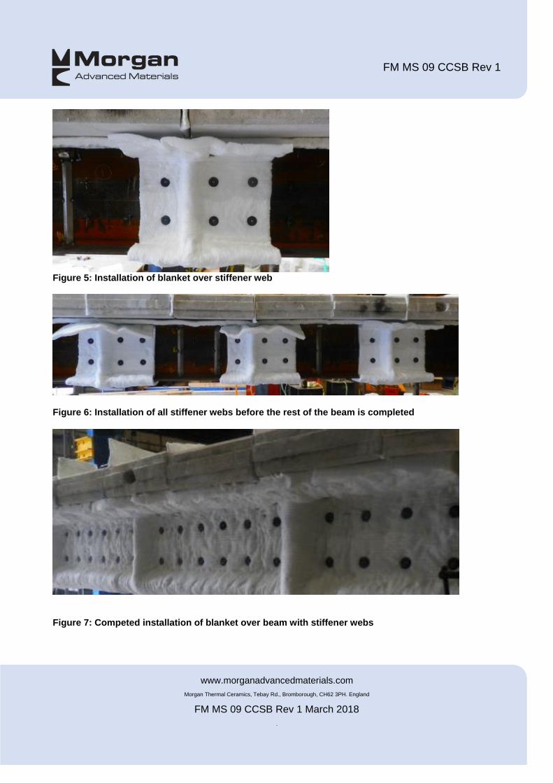
3.4.5 Installation on beams with stiffening webs
On beams with stiffening webs, the blanket is installed so that it fits over the web. The general anchor pin
spacing detail shown in Figure 4 is utilised to allow one full width of 610mm blanket to be installed over the
stiffener and fixed either side of it. Figure 5 shows the single 610mm wide piece of blanket installed over the
stiffener and then fixed onto the anchor pins. The stiffener webs can be insulated before the entire beam is
completed as shown in figure 6 below,
FM MS 09 CCSB Rev 1
www.morganadvancedmaterials.com
Morgan Thermal Ceramics, Tebay Rd., Bromborough, CH62 3PH. England
FM MS 09 CCSB Rev 1 March 2018
.
Figure 5: Installation of blanket over stiffener web
Figure 6: Installation of all stiffener webs before the rest of the beam is completed
Figure 7: Competed installation of blanket over beam with stiffener webs

FM MS 09 CCSB Rev 1
www.morganadvancedmaterials.com
Morgan Thermal Ceramics, Tebay Rd., Bromborough, CH62 3PH. England
FM MS 09 CCSB Rev 1 March 2018
.
3.5. Installation Method: Multiple Layer Systems
For fire protection thickness requirements greater than 52mm, the system must be installed using two layers
of blanket. The general installation technique is the same as for single layer systems except when considering
the location of joints; which must not occur at the same location in both layers.
Figure 8 below shows a typical arrangement for beams with two layers of blanket fitted
Figure 8: Installation of two layer blanket system on beams.

FM MS 09 CCSB Rev 1
www.morganadvancedmaterials.com
Morgan Thermal Ceramics, Tebay Rd., Bromborough, CH62 3PH. England
FM MS 09 CCSB Rev 1 March 2018
.
Figure 9 below shows a typical arrangement for columns with two layers of blanket fitted.
Figure 9: Installation of two layer blanket system on columns
Ensure that the joints along the length of the columns and beams for each layer are offset by a distance of
300mm on beams and 290mm on columns (i.e. half the width of the blanket installed). See Figures 10 and 11
below.

FM MS 09 CCSB Rev 1
www.morganadvancedmaterials.com
Morgan Thermal Ceramics, Tebay Rd., Bromborough, CH62 3PH. England
FM MS 09 CCSB Rev 1 March 2018
.
Figure 10: Location of offset joints on columns when two-layers of blanket are installed

FM MS 09 CCSB Rev 1
www.morganadvancedmaterials.com
Morgan Thermal Ceramics, Tebay Rd., Bromborough, CH62 3PH. England
FM MS 09 CCSB Rev 1 March 2018
.
Figure 11: Location of offset joints on beams when two-layers of blanket are installed

FM MS 09 CCSB Rev 1
www.morganadvancedmaterials.com
Morgan Thermal Ceramics, Tebay Rd., Bromborough, CH62 3PH. England
FM MS 09 CCSB Rev 1 March 2018
.
4. Installation Techniques
The blanket may be cut using a standard insulation knife. To ensure a good fit of the blanket around the
section, follow the procedure in example installation shown below.
Measure the length of blanket required using the perimeter of the steel section as an initial guide. Check that
this length of blanket can fit around the section and if not, adjust the length until a good fit is achieved and then
use this blanket length as the guide for cutting subsequent lengths. Cut a new piece of blanket and then install
that piece following this guide.
Mark the centre of the cut piece and install it over the anchor on the flange as shown above with the mark
aligned with the anchor pin. Wrap one side of the blanket around the column and fix it onto the anchor pin on
the opposite flange. Fix into place using a friction fit washer. Repeat the same method to wrap the other side
of the column

FM MS 09 CCSB Rev 1
www.morganadvancedmaterials.com
Morgan Thermal Ceramics, Tebay Rd., Bromborough, CH62 3PH. England
FM MS 09 CCSB Rev 1 March 2018
.
Push the blanket into the web of the section impaling it over the anchor pin and using the friction fit washer to
fix securely in place.
The blanket should form a tight fit into the web of the column if the length has been adjusted correctly as
described above.

FM MS 09 CCSB Rev 1
www.morganadvancedmaterials.com
Morgan Thermal Ceramics, Tebay Rd., Bromborough, CH62 3PH. England
FM MS 09 CCSB Rev 1 March 2018
.
The next piece of blanket is then fitted ensuring there is a small overlap at the edge of the adjacent blankets.
The edge of both blankets is then squeezed together to form a tight butted joint.

FM MS 09 CCSB Rev 1
www.morganadvancedmaterials.com
Morgan Thermal Ceramics, Tebay Rd., Bromborough, CH62 3PH. England
FM MS 09 CCSB Rev 1 March 2018
.
Any excess anchor length protruding from the blanket can be removed by cutting or bending the anchor pin
over as illustrated above.

FM MS 09 CCSB Rev 1
www.morganadvancedmaterials.com
Morgan Thermal Ceramics, Tebay Rd., Bromborough, CH62 3PH. England
FM MS 09 CCSB Rev 1 March 2018
.
APPENDICES
1. Declaration of Performance Document
2. UL Europe Certificate
3. European Technical Assessment Document
4. FireMaster Marine Plus Blanket Data Sheet