Embed Size (px)
Citation preview
Metal Structures
Lecture XI
Bolted joints(part II)
Contents
Technical solutions → #t / 3
Initial assumptions about geometry of different types of joints → #t / 23
Interactions and contact → #t / 32
Examination issues → #t / 92
Technical solutions
There are many different types of bolted joints between different parts and
members of structure. Which solutions of bolted joints are most often used?
Which phenomenons are important for them?
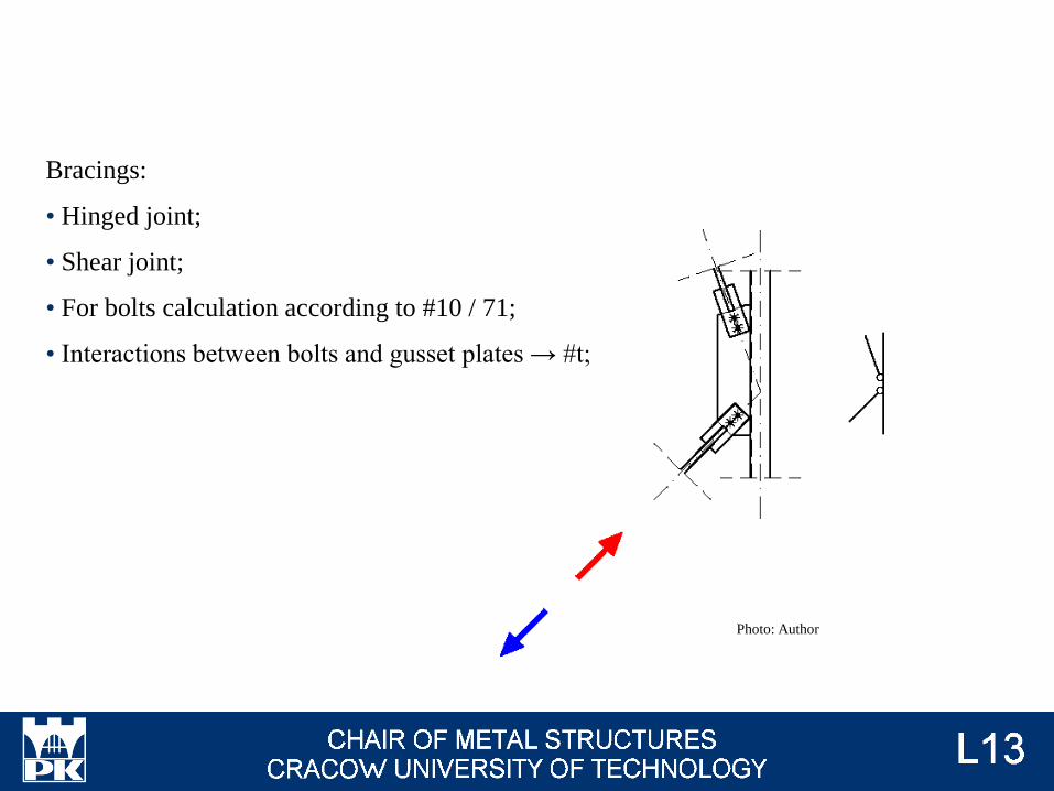
Bracings:
• Hinged joint;
• Shear joint;
• For bolts calculation according to #10 / 71;
• Interactions between bolts and gusset plates → #t;
Photo: Author
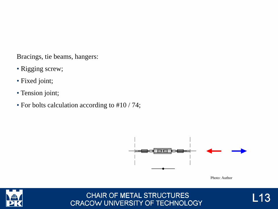
Bracings, tie beams, hangers:
• Rigging screw;
• Fixed joint;
• Tension joint;
• For bolts calculation according to #10 / 74;
Photo: Author

Bracings, tie beams:
• Hinged joint;
• Shear joint;
• For bolts calculation according to #10 / 71;
• Interactions between:
• bolts and L section → #t;
• bolts and gusset plate → #t;
Photo: Author
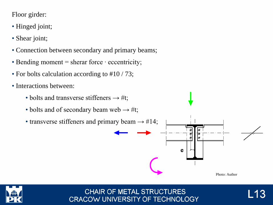
Floor girder:
• Hinged joint;
• Shear joint;
• Connection between secondary and primary beams;
• Bending moment = sherar force ∙ eccentricity;
• For bolts calculation according to #10 / 73;
• Interactions between:
• bolts and transverse stiffeners → #t;
• bolts and of secondary beam web → #t;
• transverse stiffeners and primary beam → #14;
Photo: Author
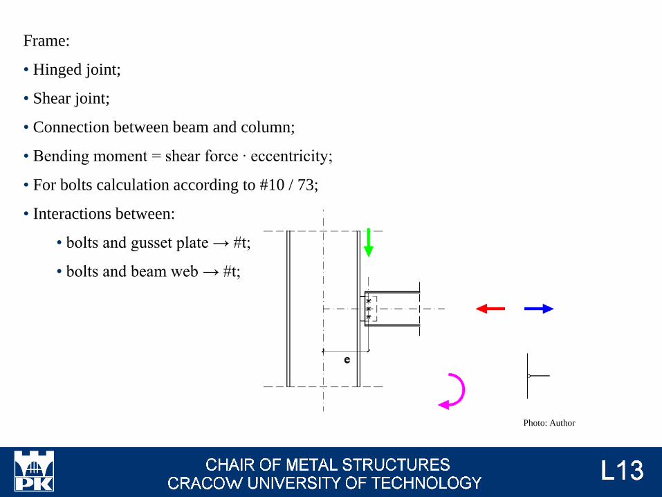
Photo: Author
Frame:
• Hinged joint;
• Shear joint;
• Connection between beam and column;
• Bending moment = shear force ∙ eccentricity;
• For bolts calculation according to #10 / 73;
• Interactions between:
• bolts and gusset plate → #t;
• bolts and beam web → #t;
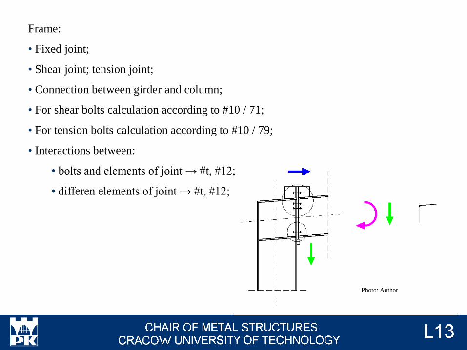
Frame:
• Fixed joint;
• Shear joint; tension joint;
• Connection between girder and column;
• For shear bolts calculation according to #10 / 71;
• For tension bolts calculation according to #10 / 79;
• Interactions between:
• bolts and elements of joint → #t, #12;
• differen elements of joint → #t, #12;
Photo: Author
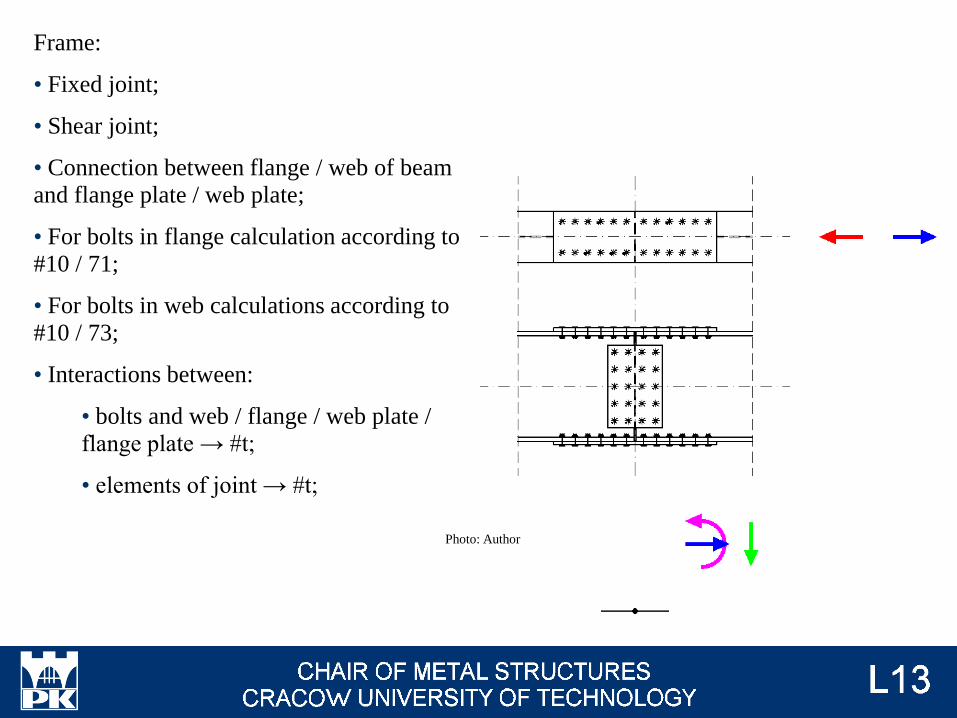
Frame:
• Fixed joint;
• Shear joint;
• Connection between flange / web of beam
and flange plate / web plate;
• For bolts in flange calculation according to
#10 / 71;
• For bolts in web calculations according to
#10 / 73;
• Interactions between:
• bolts and web / flange / web plate /
flange plate → #t;
• elements of joint → #t;
Photo: Author
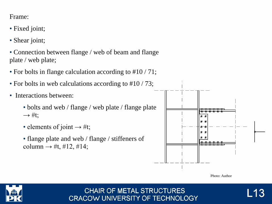
Frame:
• Fixed joint;
• Shear joint;
• Connection between flange / web of beam and flange
plate / web plate;
• For bolts in flange calculation according to #10 / 71;
• For bolts in web calculations according to #10 / 73;
• Interactions between:
• bolts and web / flange / web plate / flange plate
→ #t;
• elements of joint → #t;
• flange plate and web / flange / stiffeners of
column → #t, #12, #14;
Photo: Author
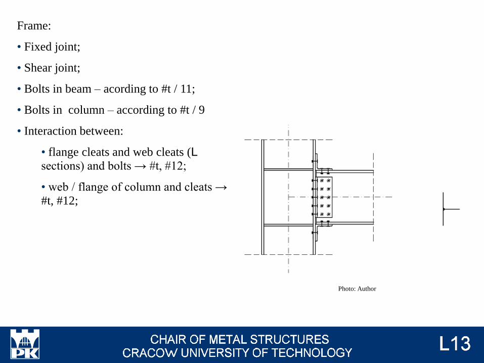
Frame:
• Fixed joint;
• Shear joint;
• Bolts in beam – acording to #t / 11;
• Bolts in column – according to #t / 9
• Interaction between:
• flange cleats and web cleats (L sections) and bolts → #t, #12;
• web / flange of column and cleats →
#t, #12;
Photo: Author
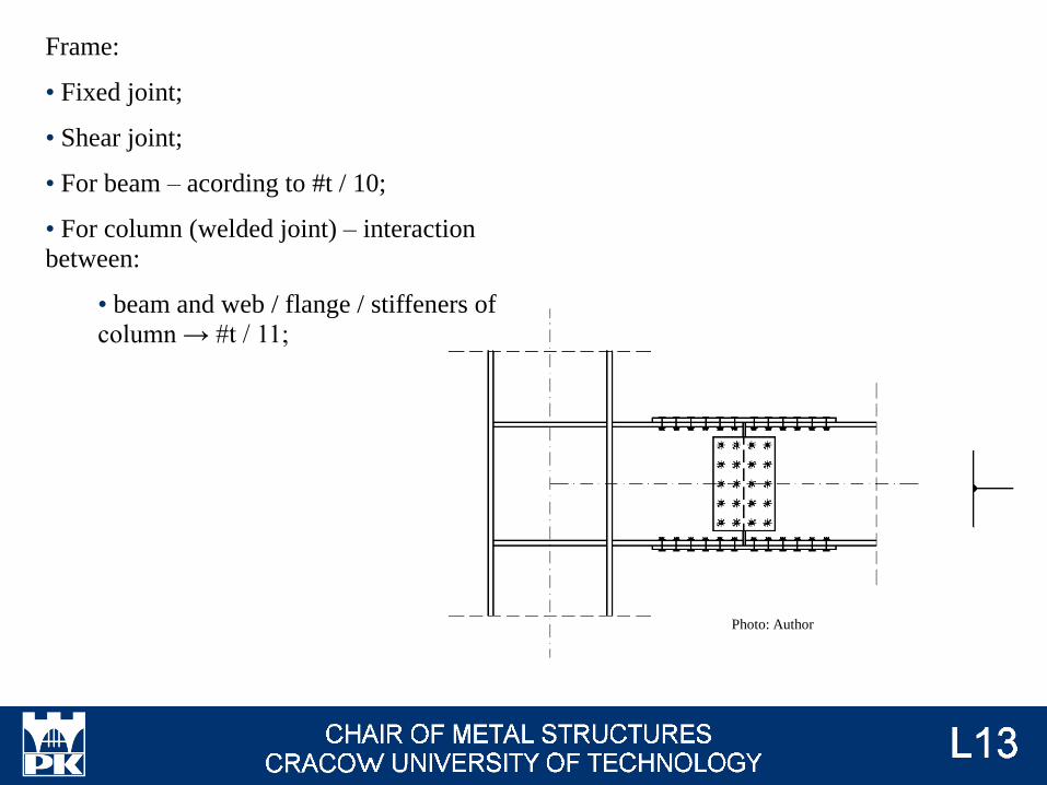
Frame:
• Fixed joint;
• Shear joint;
• For beam – acording to #t / 10;
• For column (welded joint) – interaction
between:
• beam and web / flange / stiffeners of
column → #t / 11;
Photo: Author
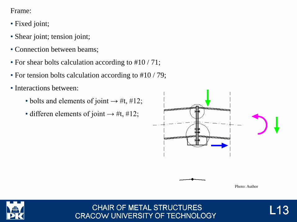
Frame:
• Fixed joint;
• Shear joint; tension joint;
• Connection between beams;
• For shear bolts calculation according to #10 / 71;
• For tension bolts calculation according to #10 / 79;
• Interactions between:
• bolts and elements of joint → #t, #12;
• differen elements of joint → #t, #12;
Photo: Author
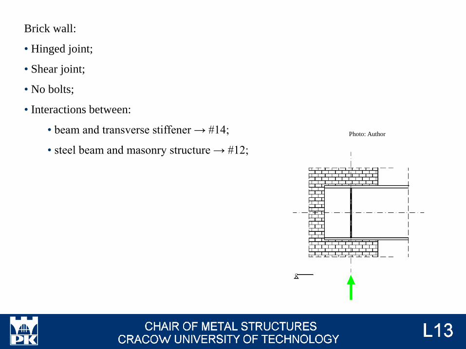
Brick wall:
• Hinged joint;
• Shear joint;
• No bolts;
• Interactions between:
• beam and transverse stiffener → #14;
• steel beam and masonry structure → #12;
Photo: Author
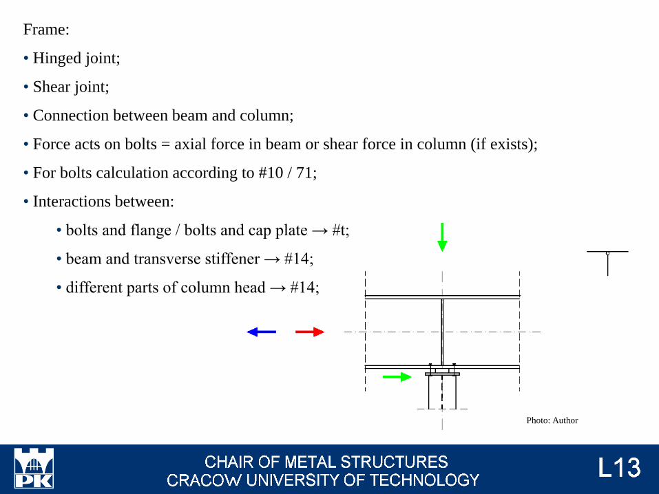
Frame:
• Hinged joint;
• Shear joint;
• Connection between beam and column;
• Force acts on bolts = axial force in beam or shear force in column (if exists);
• For bolts calculation according to #10 / 71;
• Interactions between:
• bolts and flange / bolts and cap plate → #t;
• beam and transverse stiffener → #14;
• different parts of column head → #14;
Photo: Author
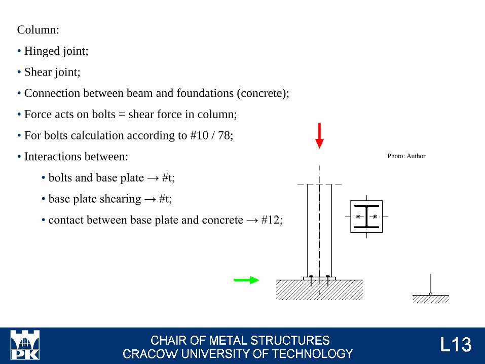
Column:
• Hinged joint;
• Shear joint;
• Connection between beam and foundations (concrete);
• Force acts on bolts = shear force in column;
• For bolts calculation according to #10 / 78;
• Interactions between:
• bolts and base plate → #t;
• base plate shearing → #t;
• contact between base plate and concrete → #12;
Photo: Author
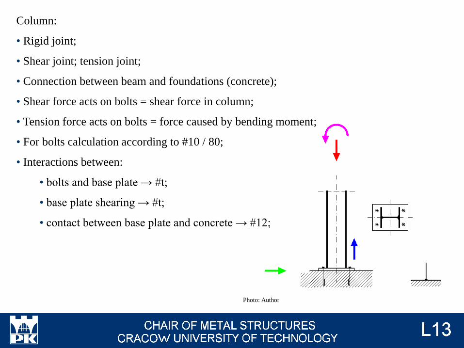
Column:
• Rigid joint;
• Shear joint; tension joint;
• Connection between beam and foundations (concrete);
• Shear force acts on bolts = shear force in column;
• Tension force acts on bolts = force caused by bending moment;
• For bolts calculation according to #10 / 80;
• Interactions between:
• bolts and base plate → #t;
• base plate shearing → #t;
• contact between base plate and concrete → #12;
Photo: Author
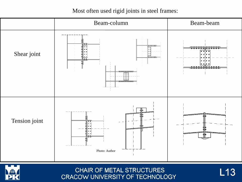
Beam-column Beam-beam
Shear joint
Tension joint
Photo: Author
Most often used rigid joints in steel frames:
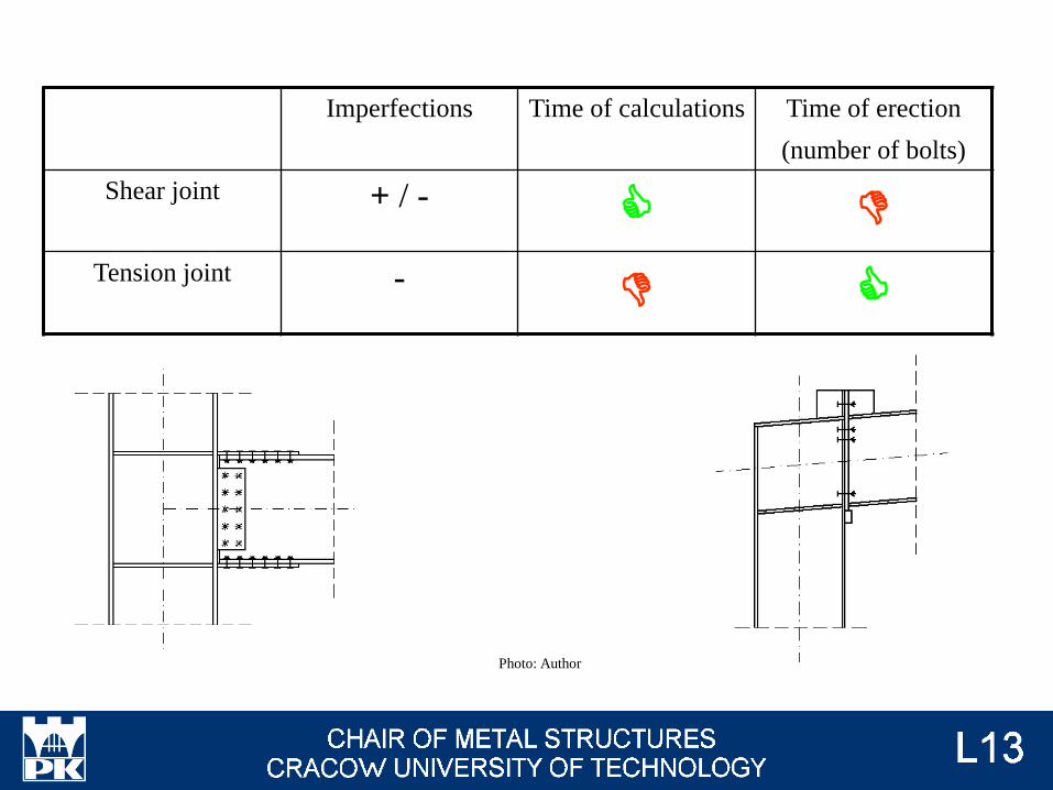
Imperfections Time of calculations Time of erection
(number of bolts)
Shear joint + / -C D
Tension joint -D C
Photo: Author
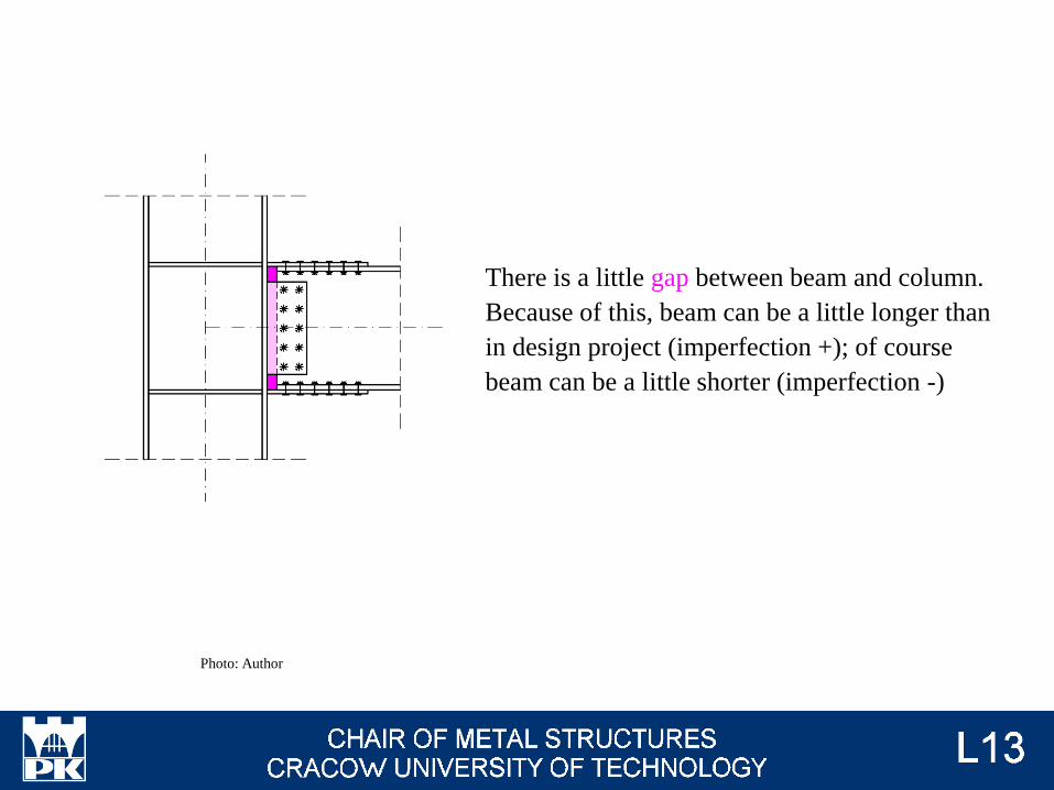
There is a little gap between beam and column.
Because of this, beam can be a little longer than
in design project (imperfection +); of course
beam can be a little shorter (imperfection -)
Photo: Author

Because of collision between beam and column,
beam can't be longer (imperfection + impossible).
Beam can be little shorter (imperfection -); in this
situation we must use additional packing plate.
Photo: Author
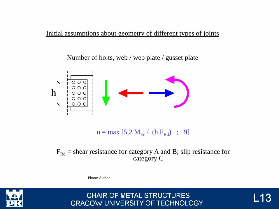
n = max [5,2 MEd / (h FRd) ; 9]
FRd = shear resistance for category A and B; slip resistance for category C
Initial assumptions about geometry of different types of joints
Number of bolts, web / web plate / gusset plate
Photo: Author
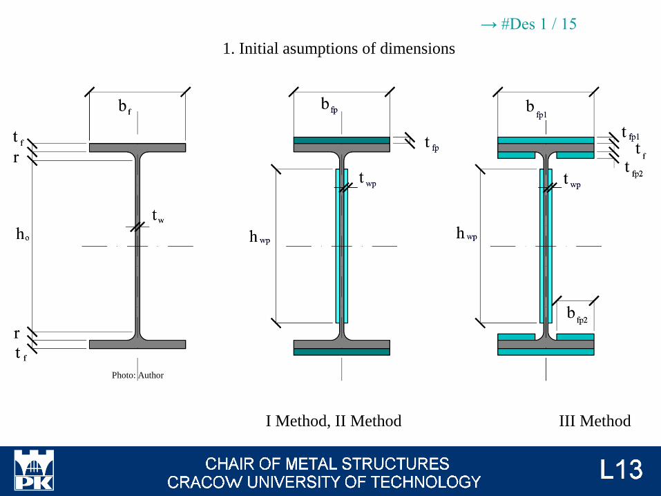
I Method, II Method III Method
1. Initial asumptions of dimensions
Photo: Author
→ #Des 1 / 15
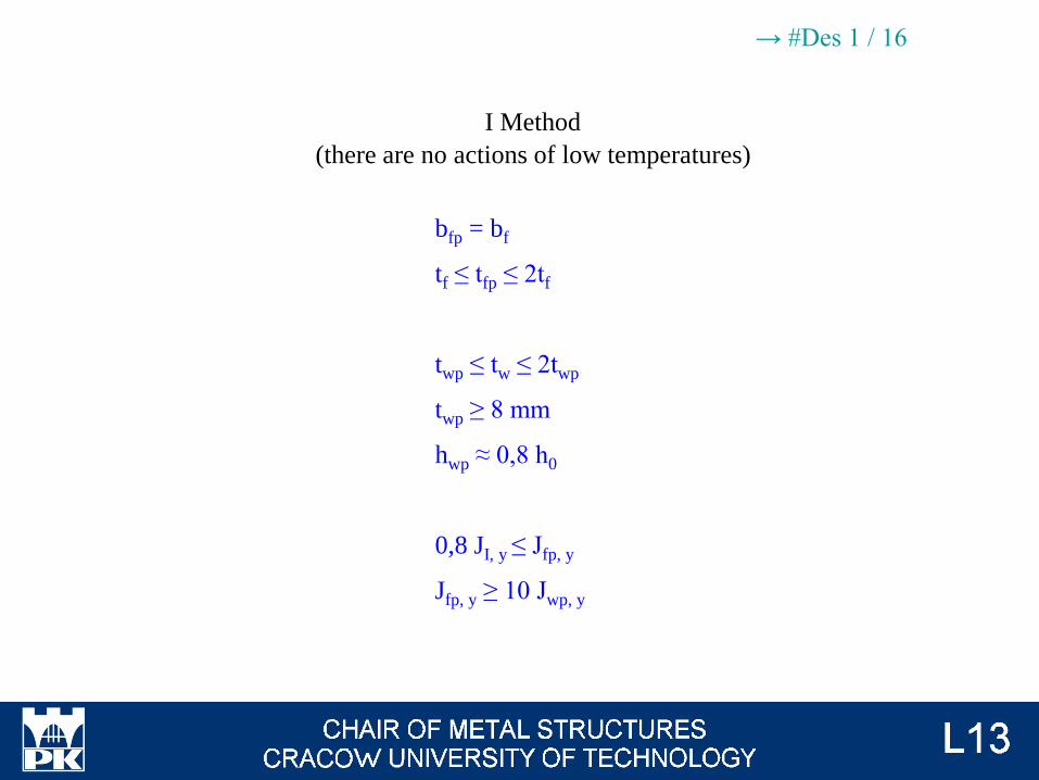
bfp = bf
tf ≤ tfp ≤ 2tf
twp ≤ tw ≤ 2twp
twp ≥ 8 mm
hwp ≈ 0,8 h0
0,8 JI, y ≤ Jfp, y
Jfp, y ≥ 10 Jwp, y
I Method
(there are no actions of low temperatures)
→ #Des 1 / 16
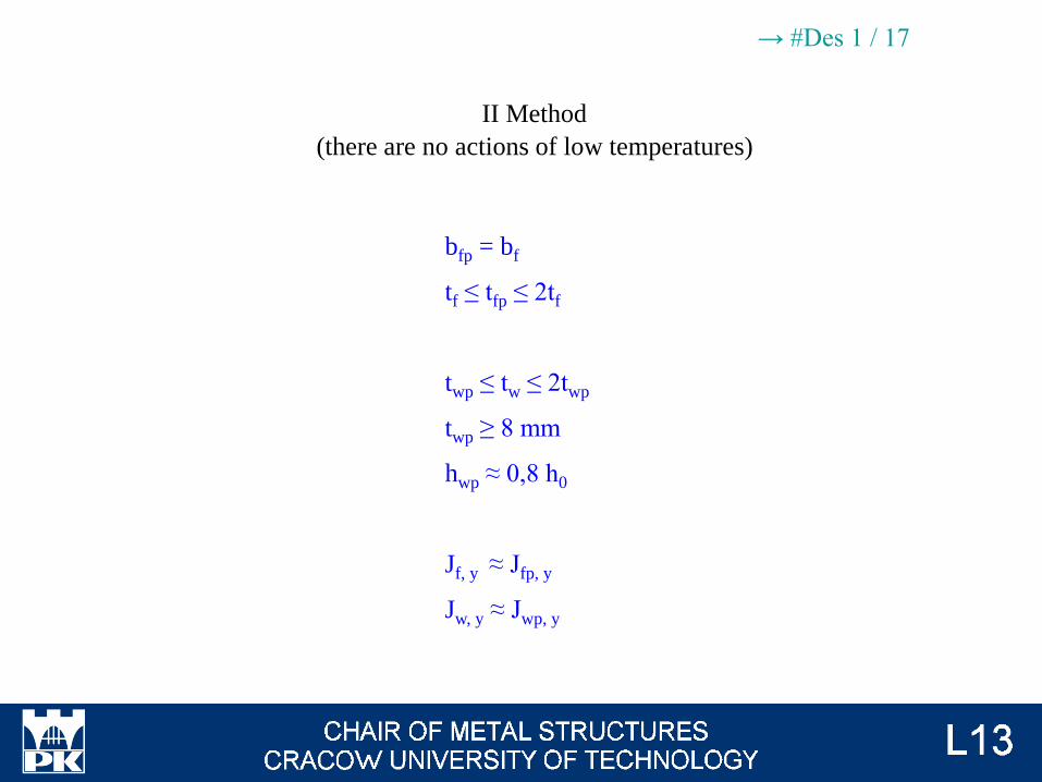
bfp = bf
tf ≤ tfp ≤ 2tf
twp ≤ tw ≤ 2twp
twp ≥ 8 mm
hwp ≈ 0,8 h0
Jf, y ≈ Jfp, y
Jw, y ≈ Jwp, y
II Method
(there are no actions of low temperatures)
→ #Des 1 / 17
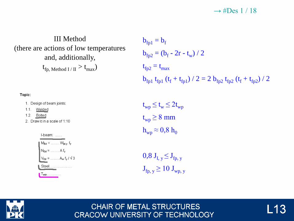
III Method
(there are actions of low temperatures
and, additionally,
tfp, Method I / II > tmax)
bfp1 = bf
bfp2 = (bf - 2r - tw) / 2
tfp2 = tmax
bfp1 tfp1 (tf + tfp1) / 2 = 2 bfp2 tfp2 (tf + tfp2) / 2
twp ≤ tw ≤ 2twp
twp ≥ 8 mm
hwp ≈ 0,8 h0
0,8 JI, y ≤ Jfp, y
Jfp, y ≥ 10 Jwp, y
→ #Des 1 / 18
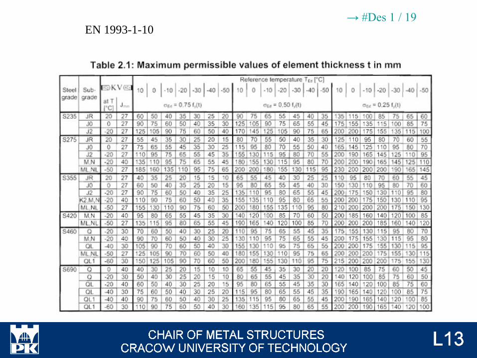
EN 1993-1-10→ #Des 1 / 19
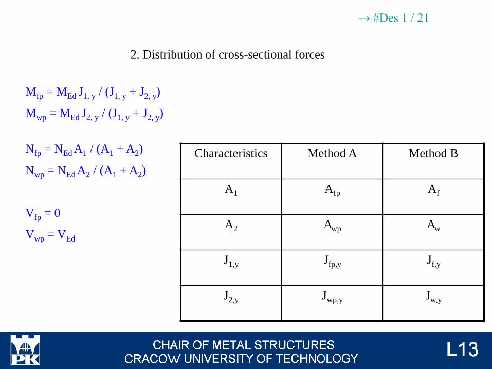
Mfp = MEd J1, y / (J1, y + J2, y)
Mwp = MEd J2, y / (J1, y + J2, y)
Nfp = NEd A1 / (A1 + A2)
Nwp = NEd A2 / (A1 + A2)
Vfp = 0
Vwp = VEd
2. Distribution of cross-sectional forces
Characteristics Method A Method B
A1 Afp Af
A2 Awp Aw
J1,y Jfp,y Jf,y
J2,y Jwp,y Jw,y
→ #Des 1 / 21
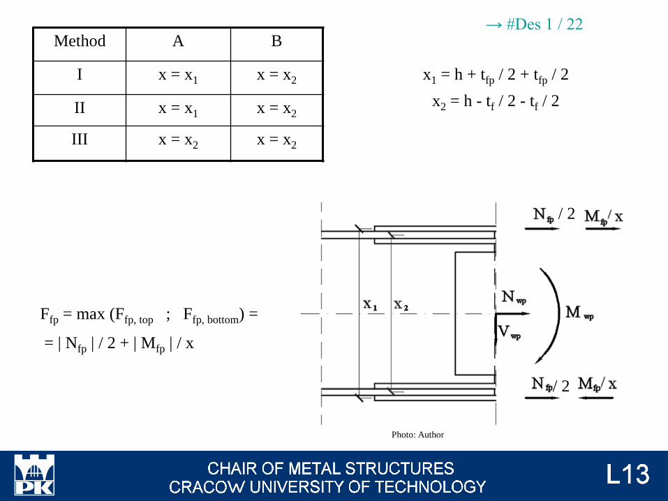
Ffp = max (Ffp, top ; Ffp, bottom) =
= | Nfp | / 2 + | Mfp | / x
/ 2
/ 2
Method A B
I x = x1 x = x2
II x = x1 x = x2
III x = x2 x = x2
x1 = h + tfp / 2 + tfp / 2
x2 = h - tf / 2 - tf / 2
Photo: Author
→ #Des 1 / 22

min (t1 ; t2) ≥ max (T1 ; T2)
T1 = 2,0 √ {c Ft,Rd / [fy (2c + d)]}
T2 = 1,67 d 3√ {fub / 1 000 [MPa]}
Tension connection – thickness of end plate (t1) and additional
plate for column flange (t1 = tflange + tplate)
Photo: Author
Type of bolts
Bearin
g resistan
ce
Base p
lates shearin
g
Punch
ing resistan
ce
Pry
ing actio
ns
Plate / flan
ge in
ben
din
g
Web
in ten
sion
t/39-
52
t/72-
74
t/75 t/76-
79
t/80-90
Shear
"normal" A ✓ ✓
preloaded
B ✓ ✓
C ✓ ✓
Ten
sion
"normal" D ✓ ✓ ✓ ✓
preloaded E ✓ ✓ ✓ ✓
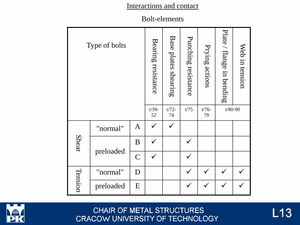
Interactions and contact
Bolt-elements
Type of bolts
Net area Instab
ility o
f plate
Slip
-resistant
„Classical” n
et area
Blo
ck tearin
g
Lsectio
nt/56-65 t/53-
54
t/66-
71
Shear
"normal" A ✓ ✓ ✓ ✓
preloaded
B ✓ ✓ ✓ ✓ ✓
C ✓ ✓ ✓ ✓ ✓
Ten
sion
"normal" D
preloaded E
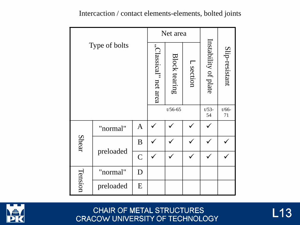
Intercaction / contact elements-elements, bolted joints
Type of bolts
Shear resistan
ce
Ten
sion resistan
ce
Differen
tty
pes
of
interactio
ns
(lec #11, 1
2)
Shear
"normal" A ✓ ✓
preloaded
B ✓ ✓
C ✓
Ten
sion
"normal" D ✓ ✓
preloaded E ✓ ✓
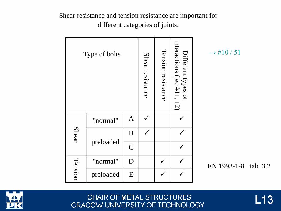
Shear resistance and tension resistance are important for
different categories of joints.
EN 1993-1-8 tab. 3.2
→ #10 / 51
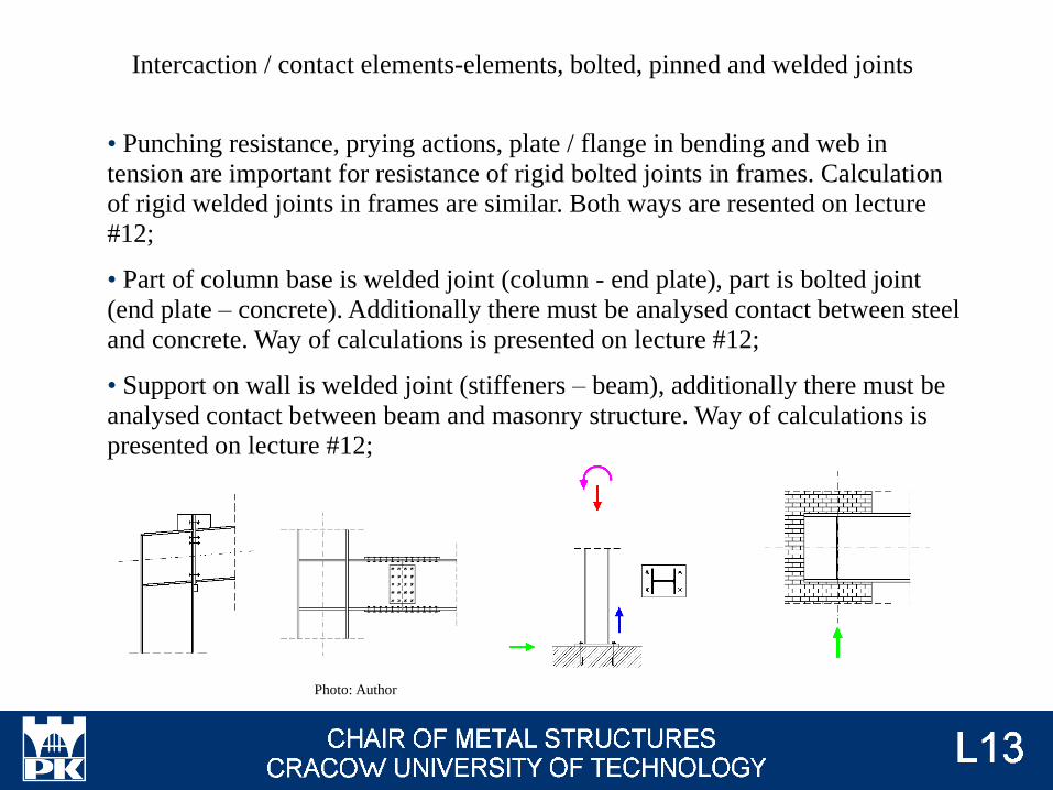
• Punching resistance, prying actions, plate / flange in bending and web in
tension are important for resistance of rigid bolted joints in frames. Calculation
of rigid welded joints in frames are similar. Both ways are resented on lecture
#12;
• Part of column base is welded joint (column - end plate), part is bolted joint
(end plate – concrete). Additionally there must be analysed contact between steel
and concrete. Way of calculations is presented on lecture #12;
• Support on wall is welded joint (stiffeners – beam), additionally there must be
analysed contact between beam and masonry structure. Way of calculations is
presented on lecture #12;
Intercaction / contact elements-elements, bolted, pinned and welded joints
Photo: Author
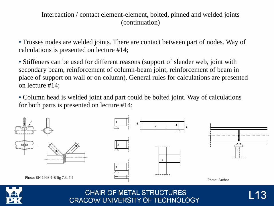
• Trusses nodes are welded joints. There are contact between part of nodes. Way of
calculations is presented on lecture #14;
• Stiffeners can be used for different reasons (support of slender web, joint with
secondary beam, reinforcement of column-beam joint, reinforcement of beam in
place of support on wall or on column). General rules for calculations are presented
on lecture #14;
• Column head is welded joint and part could be bolted joint. Way of calculations
for both parts is presented on lecture #14;
Intercaction / contact element-element, bolted, pinned and welded joints
(continuation)
Photo: EN 1993-1-8 fig 7.3, 7.4 Photo: Author
• Additional rules for welded joint between L section and plate are presented on
lecture #14;
• Additional rules for welded joint between two I-beam are presented on lecture
#14;
• Additional rules for pin ended members and contact bearing stresses for pins are
presented on lecture #14;
• Bolted joint for R&CHS are presented on lecture #14.
Intercaction / contact element-element, bolted, pinned and welded joints
(continuation)
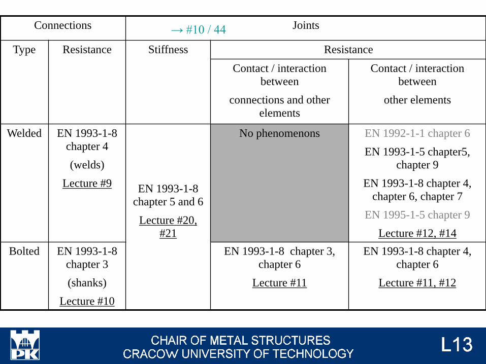
Connections Joints
Type Resistance Stiffness Resistance
Contact / interaction
between
connections and other
elements
Contact / interaction
between
other elements
Welded EN 1993-1-8
chapter 4
(welds)
Lecture #9EN 1993-1-8
chapter 5 and 6
Lecture #20, #21
No phenomenons EN 1992-1-1 chapter 6
EN 1993-1-5 chapter5, chapter 9
EN 1993-1-8 chapter 4,
chapter 6, chapter 7
EN 1995-1-5 chapter 9
Lecture #12, #14
Bolted EN 1993-1-8
chapter 3
(shanks)
Lecture #10
EN 1993-1-8 chapter 3,
chapter 6
Lecture #11
EN 1993-1-8 chapter 4,
chapter 6
Lecture #11, #12
→ #10 / 44
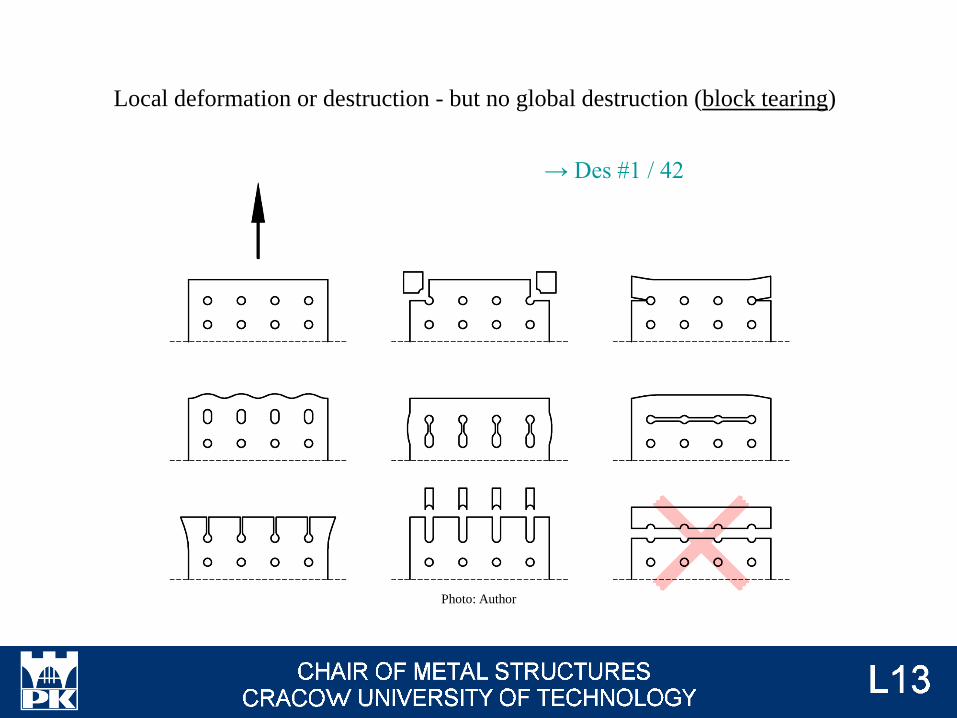
Local deformation or destruction - but no global destruction (block tearing)
Photo: Author
→ Des #1 / 42
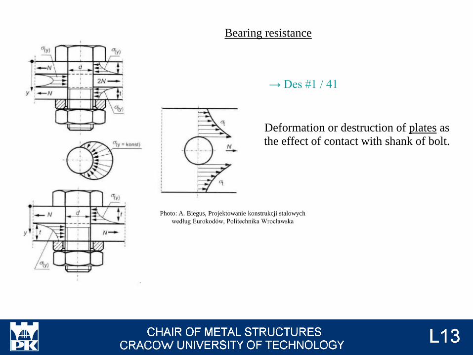
Deformation or destruction of plates as
the effect of contact with shank of bolt.
Photo: A. Biegus, Projektowanie konstrukcji stalowych
według Eurokodów, Politechnika Wrocławska
→ Des #1 / 41
Bearing resistance
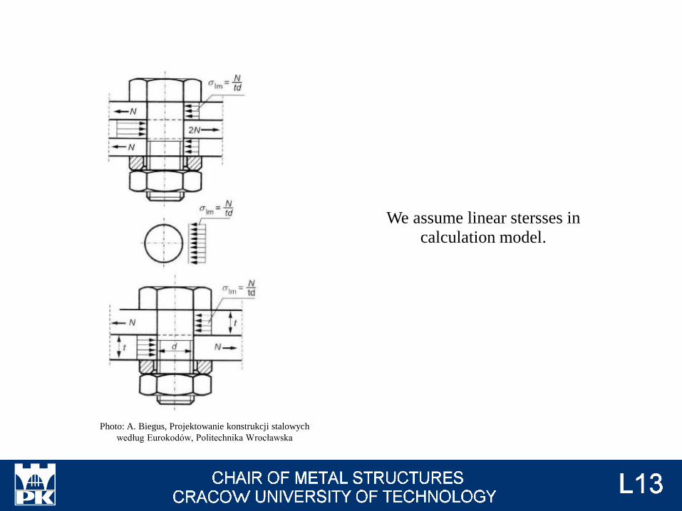
We assume linear stersses in
calculation model.
Photo: A. Biegus, Projektowanie konstrukcji stalowych
według Eurokodów, Politechnika Wrocławska
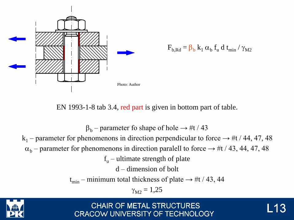
Fb,Rd = bb k1 ab fu d tmin / gM2
EN 1993-1-8 tab 3.4, red part is given in bottom part of table.
bb – parameter fo shape of hole → #t / 43
k1 – parameter for phenomenons in direction perpendicular to force → #t / 44, 47, 48
ab – parameter for phenomenons in direction paralell to force → #t / 43, 44, 47, 48
fu – ultimate strength of plate
d – dimension of bolt
tmin – minimum total thickness of plate → #t / 43, 44
gM2 = 1,25
Photo: Author
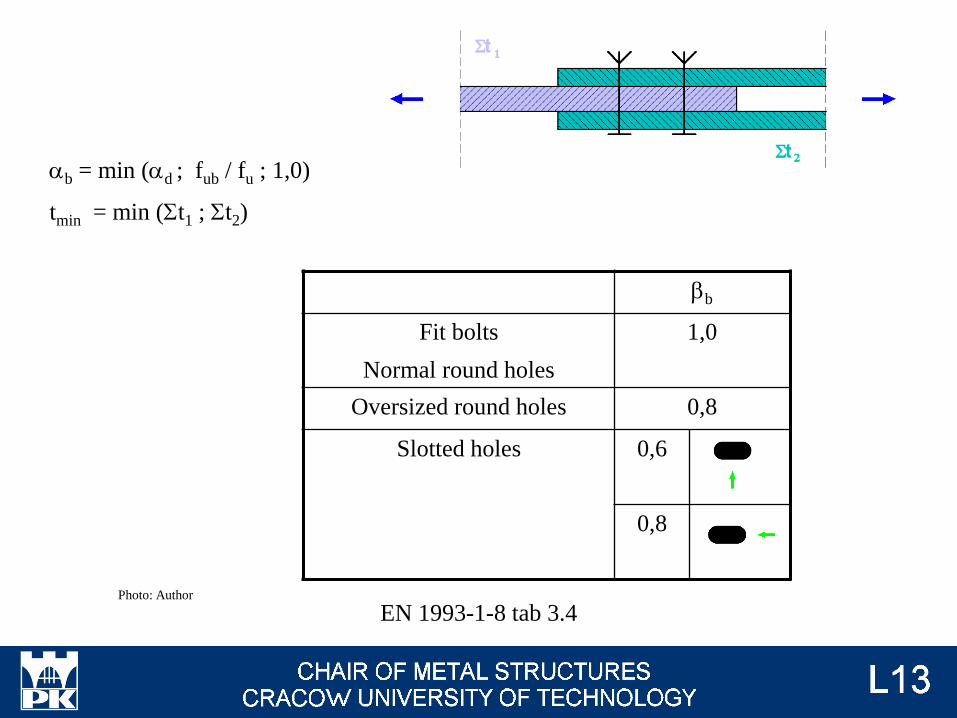
ab = min (ad ; fub / fu ; 1,0)
tmin = min (St1 ; St2)
bb
Fit bolts
Normal round holes
1,0
Oversized round holes 0,8
Slotted holes 0,6
0,8
EN 1993-1-8 tab 3.4Photo: Author
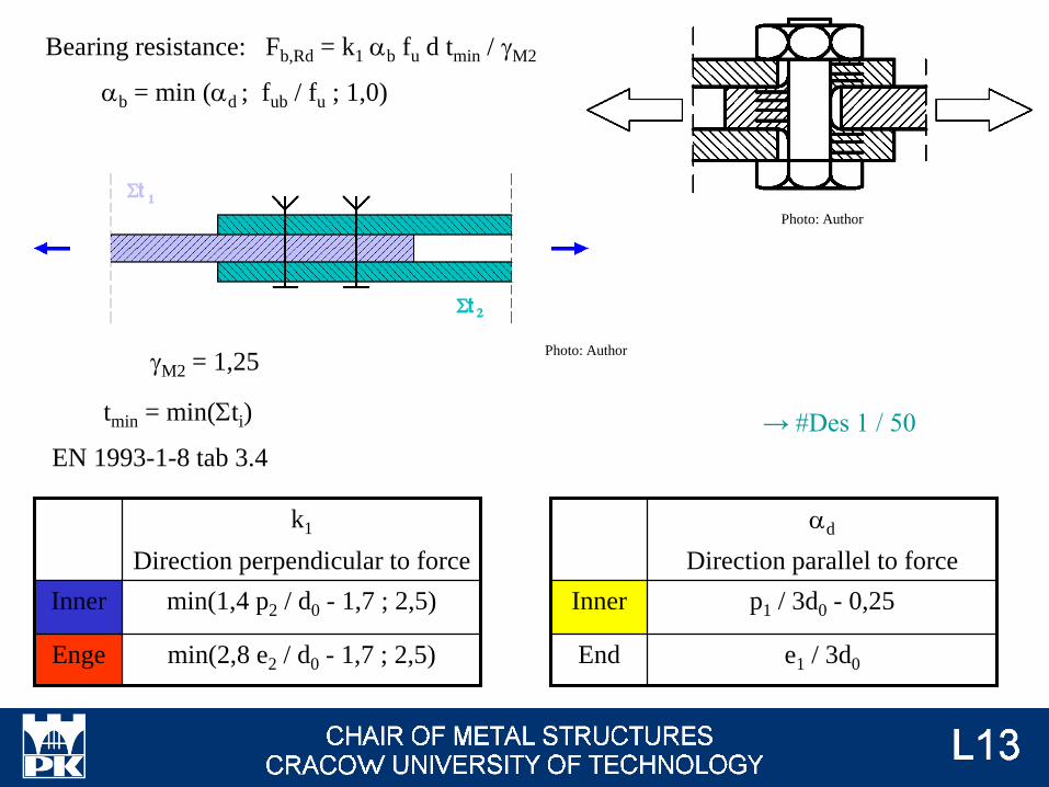
Bearing resistance: Fb,Rd = k1 ab fu d tmin / gM2
ab = min (ad ; fub / fu ; 1,0)
tmin = min(Sti)
EN 1993-1-8 tab 3.4
Photo: Author
Enge
Inner
min(2,8 e2 / d0 - 1,7 ; 2,5)
min(1,4 p2 / d0 - 1,7 ; 2,5)
k1
Direction perpendicular to force
End
Inner
e1 / 3d0
p1 / 3d0 - 0,25
ad
Direction parallel to force
Photo: AuthorgM2 = 1,25
→ #Des 1 / 50
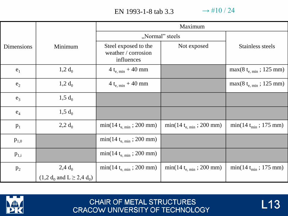
EN 1993-1-8 tab 3.3
Dimensions Minimum
Maximum
„Normal” steels
Stainless steelsSteel exposed to the
weather / corrosion influences
Not exposed
e1 1,2 d0 4 te, min + 40 mm max(8 te, min ; 125 mm)
e2 1,2 d0 4 te, min + 40 mm max(8 te, min ; 125 mm)
e3 1,5 d0
e4 1,5 d0
p1 2,2 d0 min(14 te, min ; 200 mm) min(14 te, min ; 200 mm) min(14 tmin ; 175 mm)
p1,0 min(14 te, min ; 200 mm)
p1,i min(14 te, min ; 200 mm)
p2 2,4 d0
(1,2 d0 and L ≥ 2,4 d0)
min(14 te, min ; 200 mm) min(14 te, min ; 200 mm) min(14 tmin ; 175 mm)
→ #10 / 24
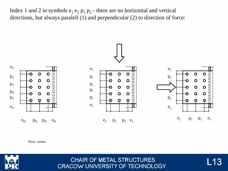
Index 1 and 2 in symbols e1 e2 p1 p2 - there are no horizontal and vertical
directions, but always paralell (1) and perpendicular (2) to direction of force:
eH eHpH pH
eV
eV
pV
pV
pV
pV
e2e2 p2 p2
e2
e2
p2
p2
e1
e1
p1
p1
p1
p1
e1e1 p1 p1
Photo: Author
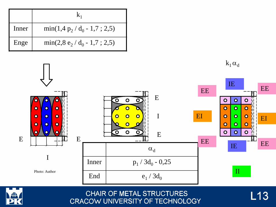
E E
I
k1
Inner min(1,4 p2 / d0 - 1,7 ; 2,5)
Enge min(2,8 e2 / d0 - 1,7 ; 2,5)
E
E
I
ad
Inner p1 / 3d0 - 0,25
End e1 / 3d0
k1 ad
EE EE
EE EE
EI EI
IE
IE
IIPhoto: Author
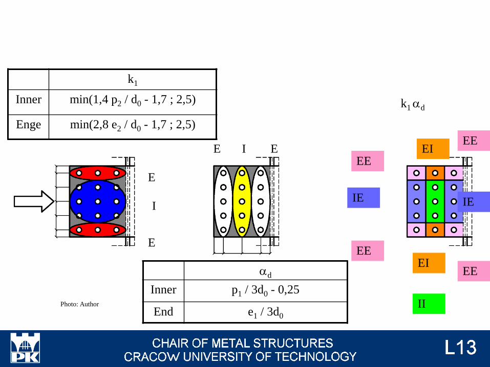
E
E
I
k1
Inner min(1,4 p2 / d0 - 1,7 ; 2,5)
Enge min(2,8 e2 / d0 - 1,7 ; 2,5)
EE I
ad
Inner p1 / 3d0 - 0,25
End e1 / 3d0
k1 ad
EE
EE
EE
EE
EI
EI
IE IE
IIPhoto: Author
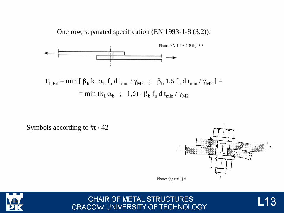
One row, separated specification (EN 1993-1-8 (3.2)):
Fb,Rd = min [ bb k1 ab fu d tmin / gM2 ; bb 1,5 fu d tmin / gM2 ] =
= min (k1 ab ; 1,5) ∙ bb fu d tmin / gM2
Photo: EN 1993-1-8 fig. 3.3
Symbols according to #t / 42
Photo: fgg.uni-lj.si
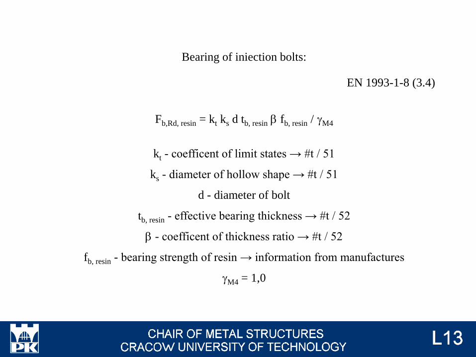
Bearing of iniection bolts:
Fb,Rd, resin = kt ks d tb, resin b fb, resin / gM4
kt - coefficent of limit states → #t / 51
ks - diameter of hollow shape → #t / 51
d - diameter of bolt
tb, resin - effective bearing thickness → #t / 52
b - coefficent of thickness ratio → #t / 52
fb, resin - bearing strength of resin → information from manufactures
gM4 = 1,0
EN 1993-1-8 (3.4)
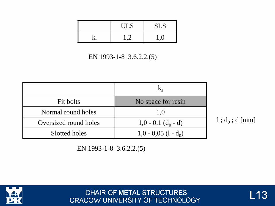
ULS SLS
kt 1,2 1,0
ks
Fit bolts No space for resin
Normal round holes 1,0
Oversized round holes 1,0 - 0,1 (d0 - d)
Slotted holes 1,0 - 0,05 (l - d0)
l ; d0 ; d [mm]
EN 1993-1-8 3.6.2.2.(5)
EN 1993-1-8 3.6.2.2.(5)
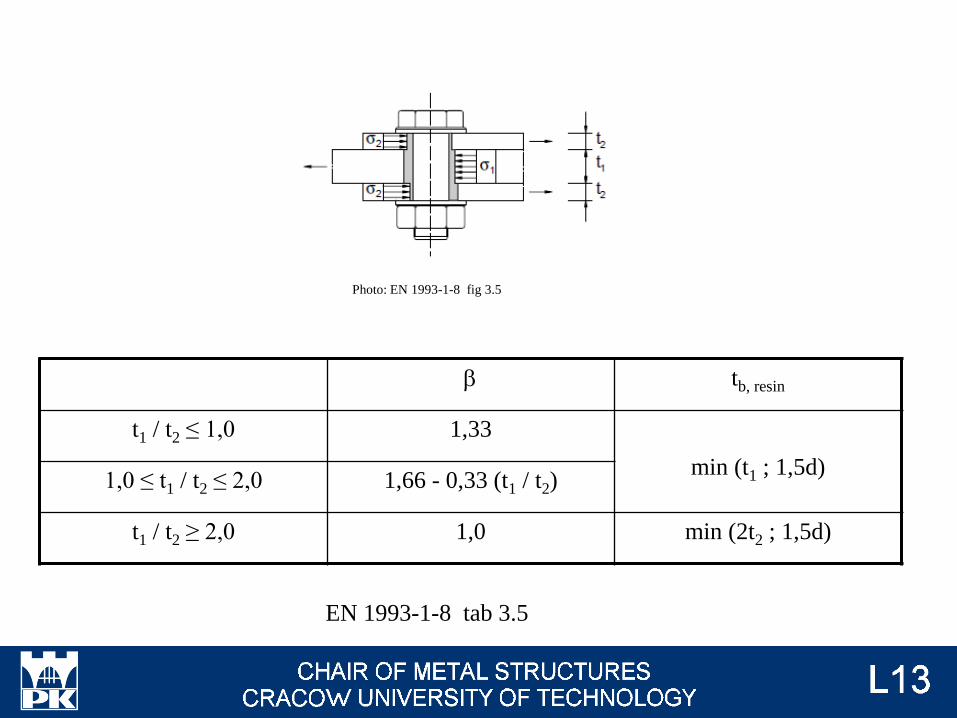
b tb, resin
t1 / t2 ≤ 1,0 1,33
min (t1 ; 1,5d)1,0 ≤ t1 / t2 ≤ 2,0 1,66 - 0,33 (t1 / t2)
t1 / t2 ≥ 2,0 1,0 min (2t2 ; 1,5d)
EN 1993-1-8 tab 3.5
Photo: EN 1993-1-8 fig 3.5
Too big distance between bolts parallel to direction of force (p1)in not recommended.
p1 / t ≥ 9e and compressive force → local buckling of plate
lcr = 0,6 p1
EN 1993-1-8 tab 3.3
More infomation will be presented on lecture #11
Local instability
→ #10 / 29
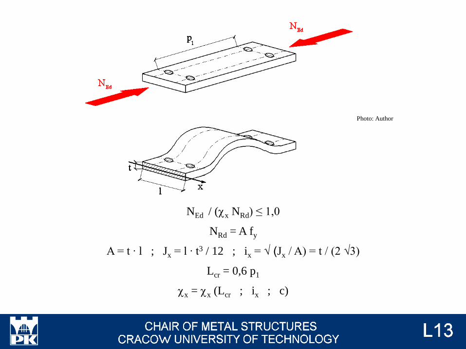
NEd / (cx NRd) ≤ 1,0
NRd = A fy
A = t ∙ l ; Jx = l ∙ t3 / 12 ; ix = √ (Jx / A) = t / (2 √3)
Lcr = 0,6 p1
cx = cx (Lcr ; ix ; c)
Photo: Author
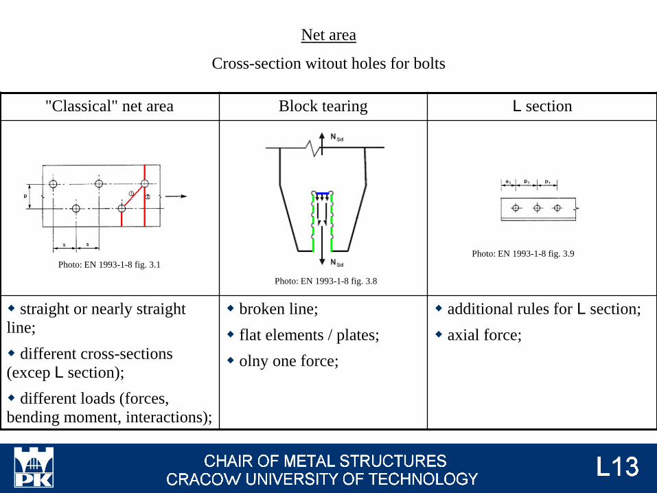
Net area
Cross-section witout holes for bolts
"Classical" net area Block tearing L section
straight or nearly straight
line;
different cross-sections
(excep L section);
different loads (forces,
bending moment, interactions);
broken line;
flat elements / plates;
olny one force;
additional rules for L section;
axial force;
Photo: EN 1993-1-8 fig. 3.9
Photo: EN 1993-1-8 fig. 3.8
Photo: EN 1993-1-8 fig. 3.1
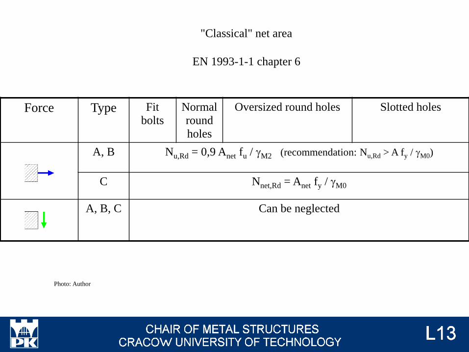
Force Type Fit
bolts
Normal
round
holes
Oversized round holes Slotted holes
A, B Nu,Rd = 0,9 Anet fu / gM2 (recommendation: Nu,Rd > A fy / gM0)
C Nnet,Rd = Anet fy / gM0
A, B, C Can be neglected
"Classical" net area
EN 1993-1-1 chapter 6
Photo: Author

Force Type Fit
bolts
Normal
round
holes
Oversized round holes Slotted holes
A, B, C Can be neglected Nc, net,Rd = Anet fy / gM2
A, B, C Can be neglected
If 0,9 Acomp, net fu / gM2 ≥ Acomp fy / gM0
then can be neglected
Otherwise Mnet,Rd = Wnet, min fy / gM2
Photo: Author

Veff, 1, Rd = fu Ant / gM2 + fy Anv / (√3 gM0) | 0,5 fu Ant / gM2 + fy Anv / (√3 gM0)
gM0 = 1,00; gM2 = 1,25
Block tearing
EN 1993-1-8 3.10.2
Photo: EN 1993-1-8 fig. 3.8
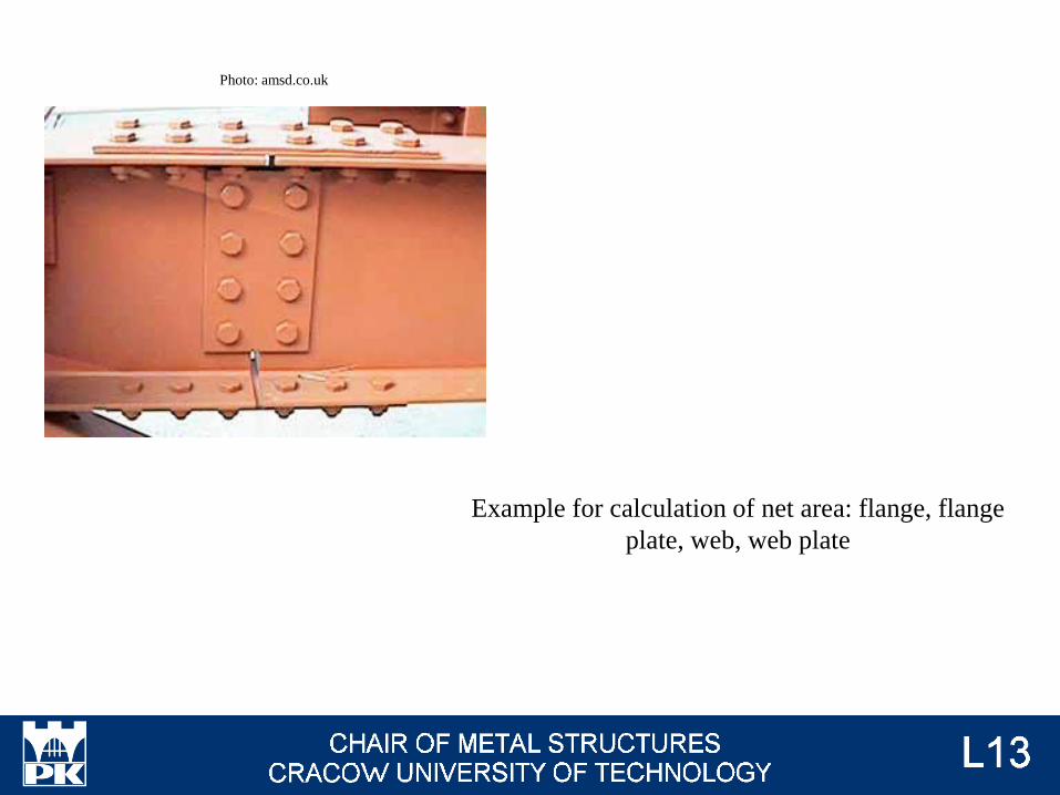
Example for calculation of net area: flange, flange
plate, web, web plate
Photo: amsd.co.uk
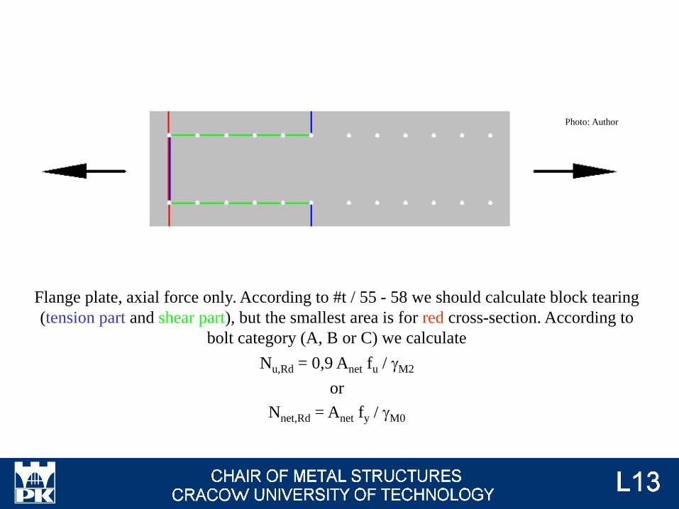
Flange plate, axial force only. According to #t / 55 - 58 we should calculate block tearing
(tension part and shear part), but the smallest area is for red cross-section. According to
bolt category (A, B or C) we calculate
Nu,Rd = 0,9 Anet fu / gM2
or
Nnet,Rd = Anet fy / gM0
Photo: Author

Web plate, bending moment, shear force and, optionally, axial force.
s(Nfp) = Nfp / Anetto
s(Mfp) = Mfp / Wnetto
t(Vfp) = Vfp / Atotal
√{ [s(Nfp) + s(Mfp)]2 + 3[t(Vfp)]
2} ≤ fy
Photo: Author
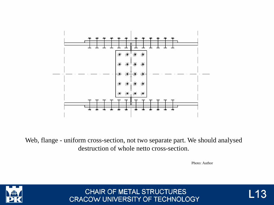
Web, flange - uniform cross-section, not two separate part. We should analysed
destruction of whole netto cross-section.
Photo: Author
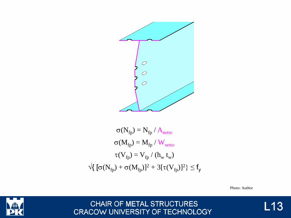
s(Nfp) = Nfp / Anetto
s(Mfp) = Mfp / Wnetto
t(Vfp) = Vfp / (hw tw)
√{ [s(Nfp) + s(Mfp)]2 + 3[t(Vfp)]
2} ≤ fy
Photo: Author
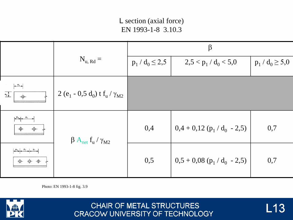
Nu, Rd =
b
p1 / d0 ≤ 2,5 2,5 < p1 / d0 < 5,0 p1 / d0 ≥ 5,0
2 (e1 - 0,5 d0) t fu / gM2
b Anet fu / gM2
0,4 0,4 + 0,12 (p1 / d0 - 2,5) 0,7
0,5 0,5 + 0,08 (p1 / d0 - 2,5) 0,7
L section (axial force)
EN 1993-1-8 3.10.3
Photo: EN 1993-1-8 fig. 3.9
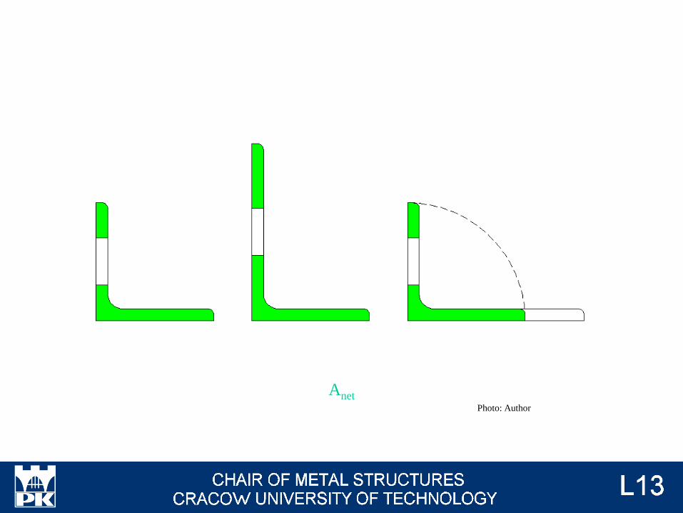
AnetPhoto: Author
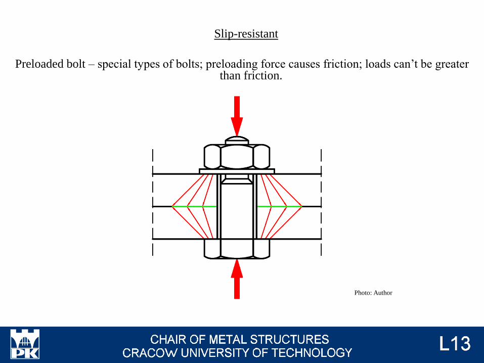
Preloaded bolt – special types of bolts; preloading force causes friction; loads can’t be greater than friction.
Slip-resistant
Photo: Author
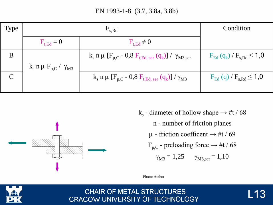
Type Fs,Rd Condition
Ft,Ed = 0 Ft,Ed ≠ 0
B
ks n m Fp,C / gM3
ks n m [Fp,C - 0,8 Ft,Ed, ser (qk)] / gM3,ser FEd (qk) / Fs,Rd ≤ 1,0
C ks n m [Fp,C - 0,8 Ft,Ed, ser (qk)] / gM3 FEd (q) / Fs,Rd ≤ 1,0
ks - diameter of hollow shape → #t / 68
n - number of friction planes
m - friction coefficent → #t / 69
Fp,C - preloading force → #t / 68
gM3 = 1,25 gM3,ser = 1,10
EN 1993-1-8 (3.7, 3.8a, 3.8b)
Photo: Author

Fp,C = 0,7 fub As
EN 1993-1-8 (3.7)
Type of holes Force ks
Round
Fit 1,0
Normal 1,0
Oversized 0,85
Slotted
Short
0,76
0,85
Long
0,63
0,70
EN 1993-1-8 tab. 3.6 Photo: Author
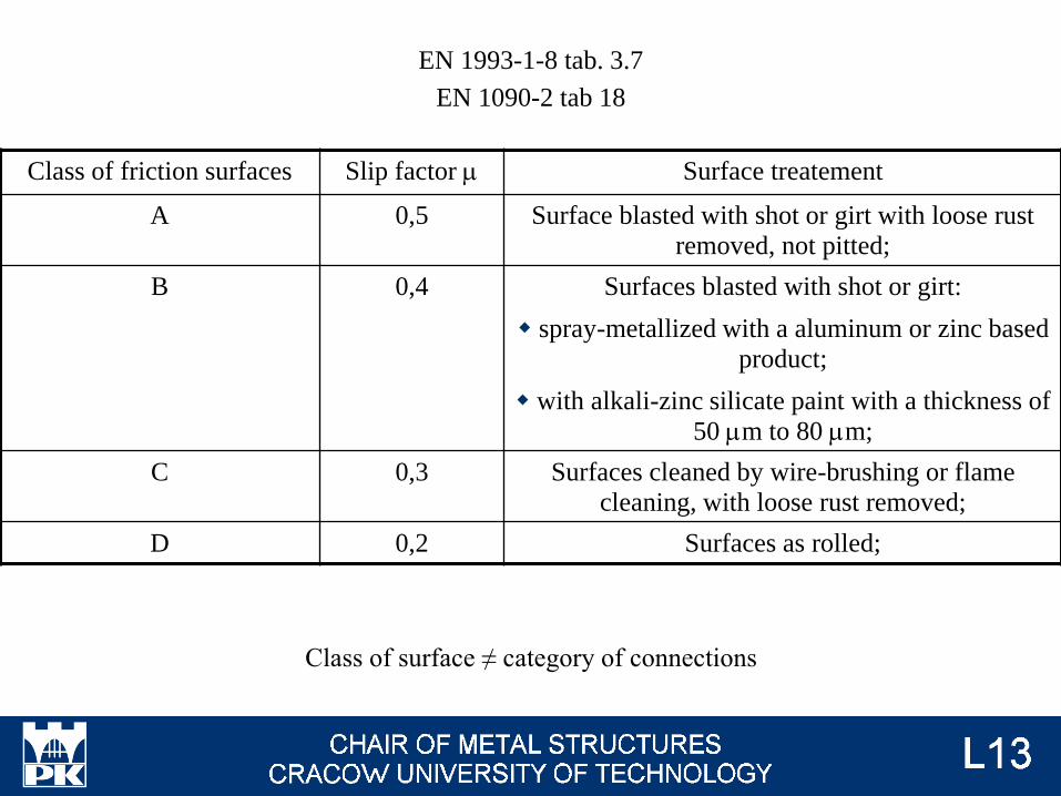
Class of surface ≠ category of connections
EN 1993-1-8 tab. 3.7
EN 1090-2 tab 18
Class of friction surfaces Slip factor m Surface treatement
A 0,5 Surface blasted with shot or girt with loose rust
removed, not pitted;
B 0,4 Surfaces blasted with shot or girt:
spray-metallized with a aluminum or zinc based
product;
with alkali-zinc silicate paint with a thickness of
50 mm to 80 mm;
C 0,3 Surfaces cleaned by wire-brushing or flame
cleaning, with loose rust removed;
D 0,2 Surfaces as rolled;
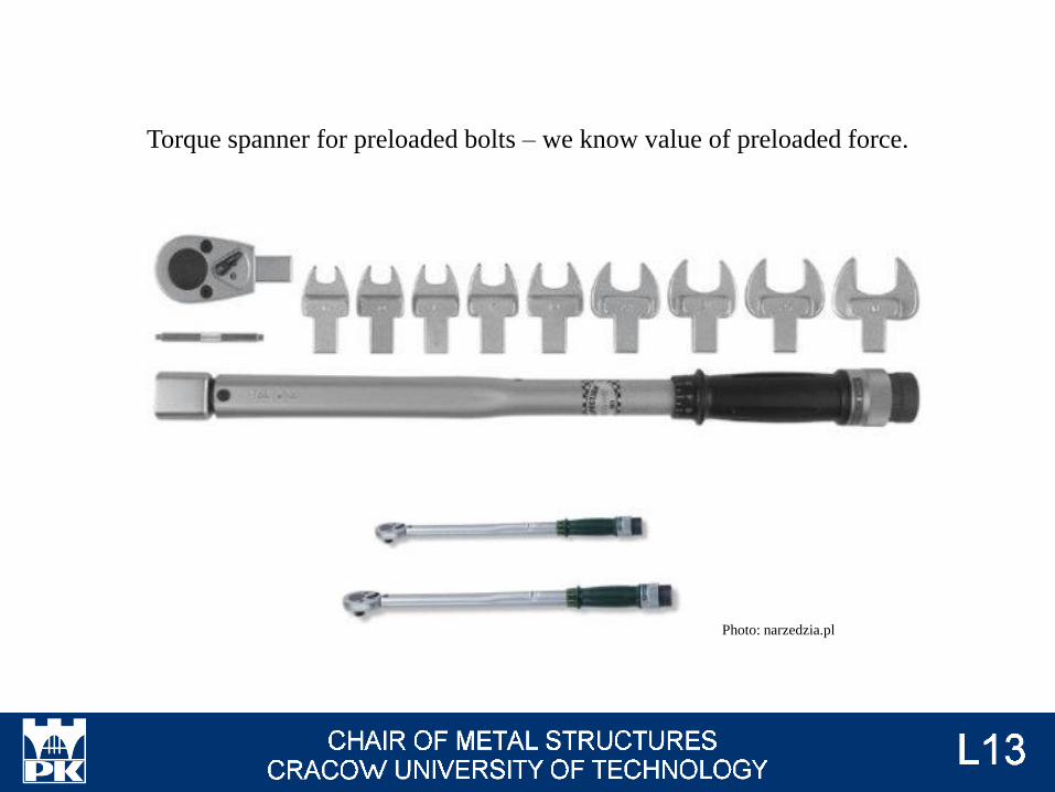
Torque spanner for preloaded bolts – we know value of preloaded force.
Photo: narzedzia.pl
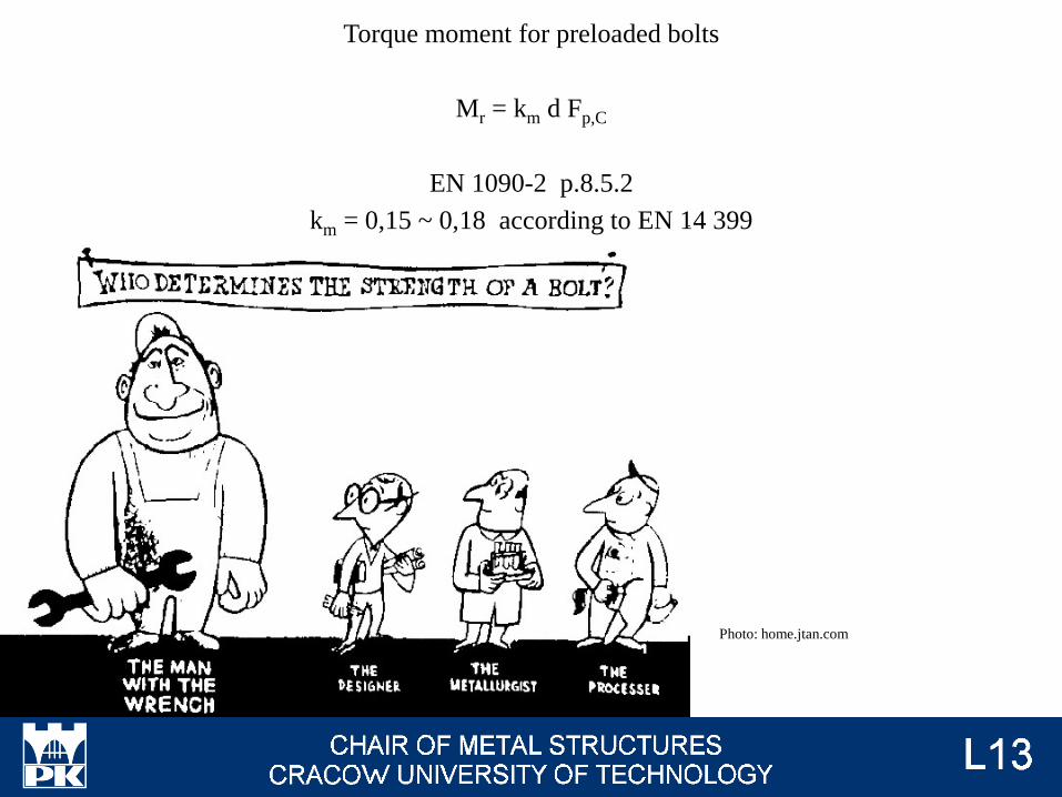
Torque moment for preloaded bolts
Mr = km d Fp,C
EN 1090-2 p.8.5.2
km = 0,15 ~ 0,18 according to EN 14 399
Photo: home.jtan.com
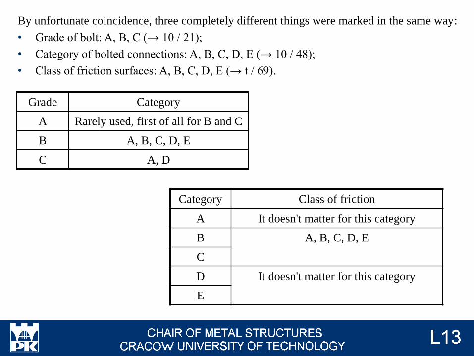
By unfortunate coincidence, three completely different things were marked in the same way:
• Grade of bolt: A, B, C (→ 10 / 21);
• Category of bolted connections: A, B, C, D, E (→ 10 / 48);
• Class of friction surfaces: A, B, C, D, E (→ t / 69).
Grade Category
A Rarely used, first of all for B and C
B A, B, C, D, E
C A, D
Category Class of friction
A It doesn't matter for this category
B A, B, C, D, E
C
D It doesn't matter for this category
E
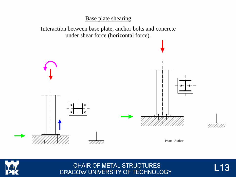
Base plate shearing
Interaction between base plate, anchor bolts and concrete
under shear force (horizontal force).
Photo: Author
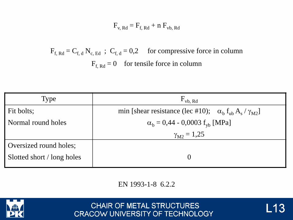
Fv, Rd = Ff, Rd + n Fvb, Rd
Ff, Rd = Cf, d Nc, Ed ; Cf, d = 0,2 for compressive force in column
Ff, Rd = 0 for tensile force in column
Type Fvb, Rd
Fit bolts;
Normal round holes
min [shear resistance (lec #10); ab fub As / gM2]
ab = 0,44 - 0,0003 fyb [MPa]
gM2 = 1,25
Oversized round holes;
Slotted short / long holes 0
EN 1993-1-8 6.2.2
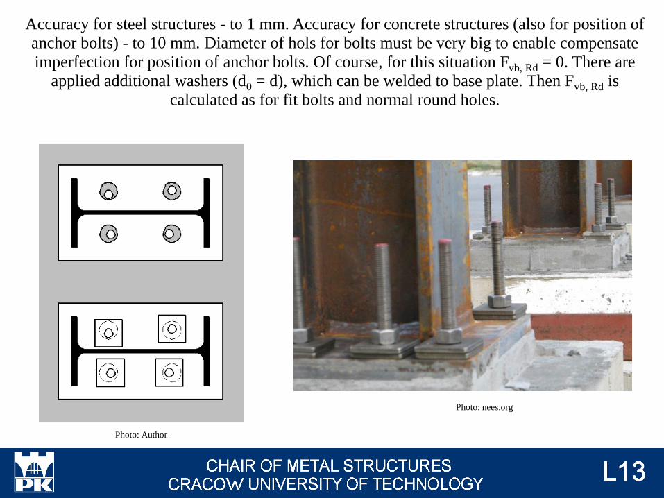
Accuracy for steel structures - to 1 mm. Accuracy for concrete structures (also for position of
anchor bolts) - to 10 mm. Diameter of hols for bolts must be very big to enable compensate
imperfection for position of anchor bolts. Of course, for this situation Fvb, Rd = 0. There are
applied additional washers (d0 = d), which can be welded to base plate. Then Fvb, Rd is
calculated as for fit bolts and normal round holes.
Photo: Author
Photo: nees.org
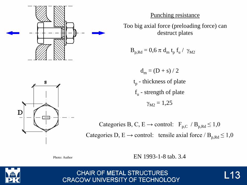
Bp,Rd = 0,6 p dm tp fu / gM2
dm = (D + s) / 2
tp - thickness of plate
fu - strength of plate
gM2 = 1,25
Categories B, C, E → control: Fp,C / Bp,Rd ≤ 1,0
Categories D, E → control: tensile axial force / Bp,Rd ≤ 1,0
EN 1993-1-8 tab. 3.4Photo: Author
Punching resistance
Too big axial force (preloading force) can
destruct plates
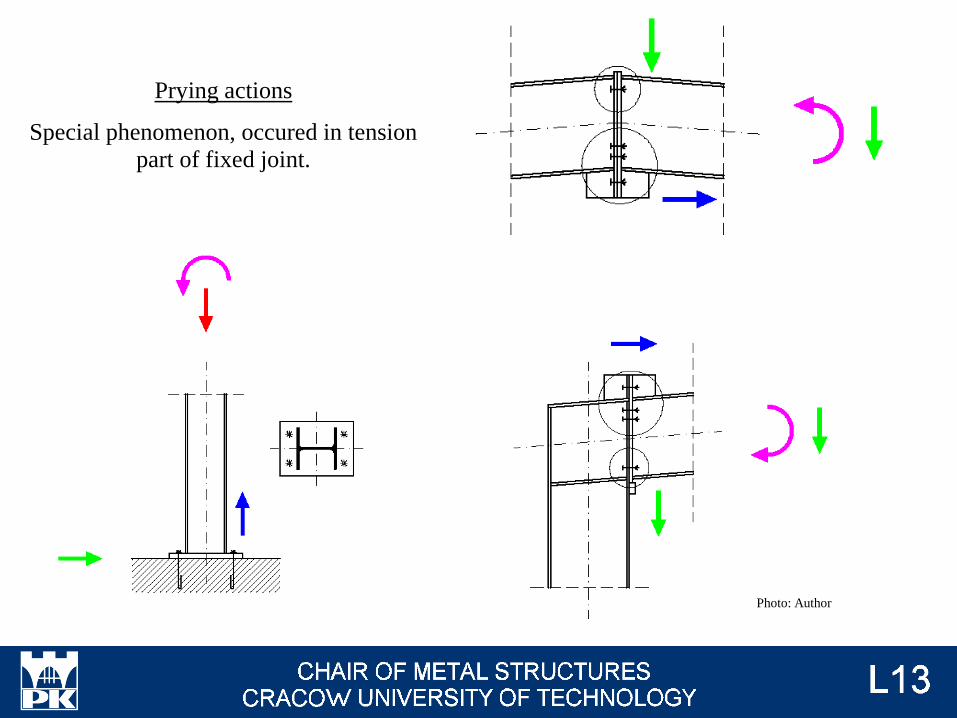
Prying actions
Special phenomenon, occured in tension
part of fixed joint.
Photo: Author
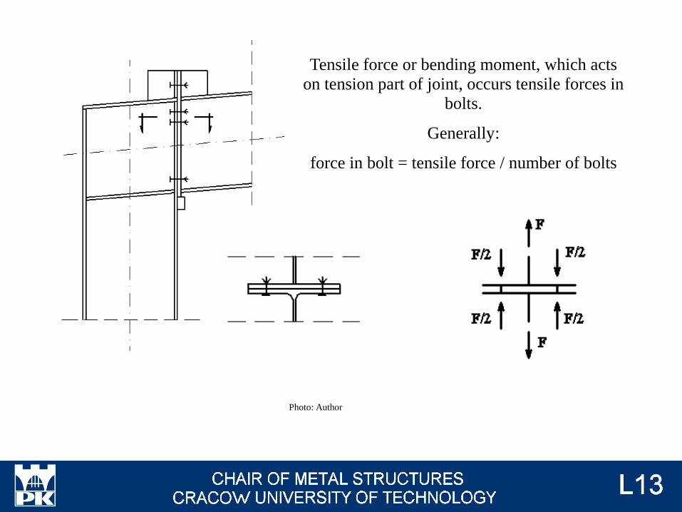
Tensile force or bending moment, which acts
on tension part of joint, occurs tensile forces in
bolts.
Generally:
force in bolt = tensile force / number of bolts
Photo: Author
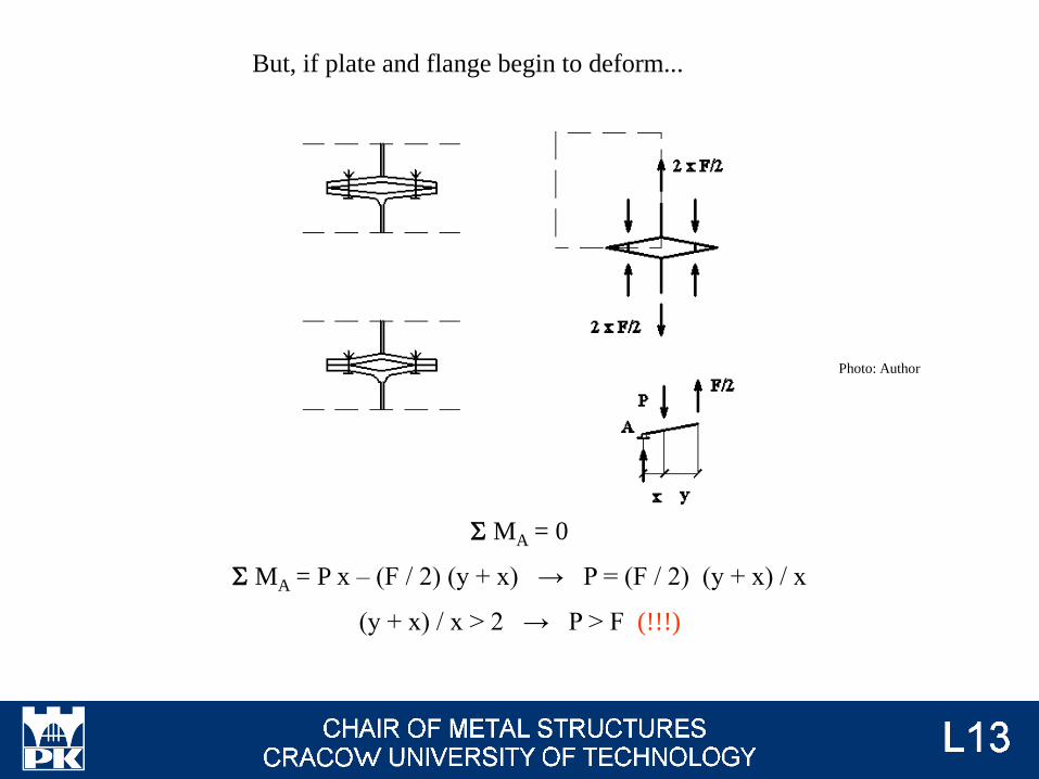
S MA = 0
S MA = P x – (F / 2) (y + x) → P = (F / 2) (y + x) / x
(y + x) / x > 2 → P > F (!!!)
But, if plate and flange begin to deform...
Photo: Author
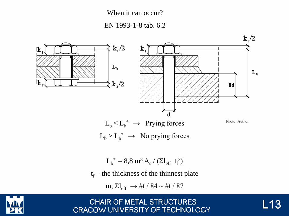
Lb ≤ Lb* → Prying forces
Lb > Lb* → No prying forces
Lb* = 8,8 m3 As / (Sleff tf
3)
tf – the thickness of the thinnest plate
m, Sleff → #t / 84 ~ #t / 87
When it can occur?
EN 1993-1-8 tab. 6.2
Photo: Author
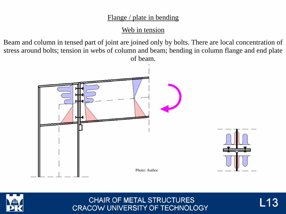
Flange / plate in bending
Web in tension
Beam and column in tensed part of joint are joined only by bolts. There are local concentration of
stress around bolts; tension in webs of column and beam; bending in column flange and end plate
of beam.
Photo: Author
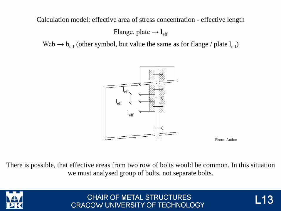
Calculation model: effective area of stress concentration - effective length
Flange, plate → leff
Web → beff (other symbol, but value the same as for flange / plate leff)
There is possible, that effective areas from two row of bolts would be common. In this situation
we must analysed group of bolts, not separate bolts.
leff
leff
leff
Photo: Author
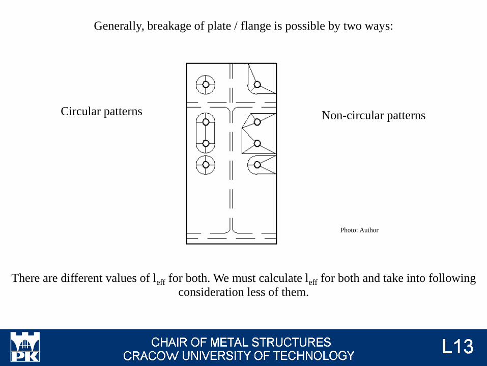
Circular patterns Non-circular patterns
Generally, breakage of plate / flange is possible by two ways:
There are different values of leff for both. We must calculate leff for both and take into following
consideration less of them.
Photo: Author
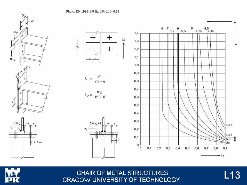
Photo: EN 1993-1-8 fig 6.8, 6.10. 6.11
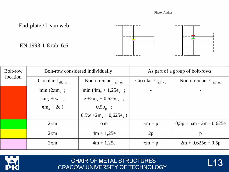
End-plate / beam web
EN 1993-1-8 tab. 6.6
Bolt-row
location
Bolt-row considered individually As part of a group of bolt-rows
Circular leff, cp Non-circular leff, nc Circular Sleff, cp Non-circular Sleff, nc
min (2pmx ;
pmx + w ;
pmx + 2e )
min (4mx + 1,25ex ;
e +2mx + 0,625ex ;
0,5bp ;
0,5w +2mx + 0,625ex )
- -
2pm am pm + p 0,5p + am - 2m - 0,625e
2pm 4m + 1,25e 2p p
2pm 4m + 1,25e pm + p 2m + 0,625e + 0,5p
Photo: Author
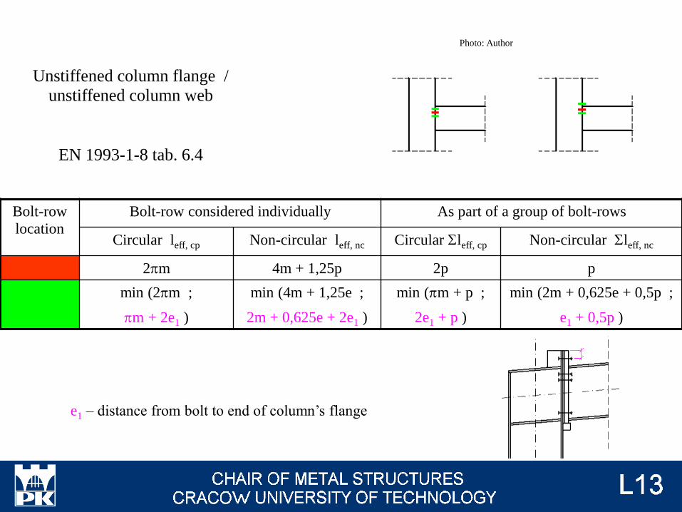
Unstiffened column flange /
unstiffened column web
EN 1993-1-8 tab. 6.4
Bolt-row
location
Bolt-row considered individually As part of a group of bolt-rows
Circular leff, cp Non-circular leff, nc Circular Sleff, cp Non-circular Sleff, nc
2pm 4m + 1,25p 2p p
min (2pm ;
pm + 2e1 )
min (4m + 1,25e ;
2m + 0,625e + 2e1 )
min (pm + p ;
2e1 + p )
min (2m + 0,625e + 0,5p ;
e1 + 0,5p )
e1 – distance from bolt to end of column’s flange
Photo: Author
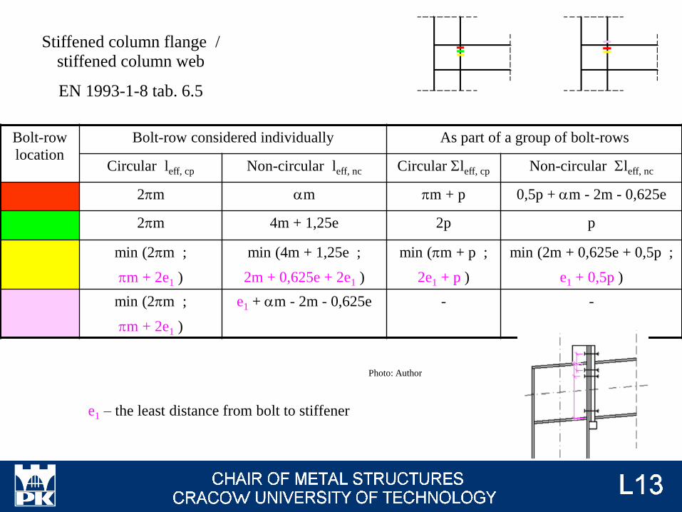
Bolt-row
location
Bolt-row considered individually As part of a group of bolt-rows
Circular leff, cp Non-circular leff, nc Circular Sleff, cp Non-circular Sleff, nc
2pm am pm + p 0,5p + am - 2m - 0,625e
2pm 4m + 1,25e 2p p
min (2pm ;
pm + 2e1 )
min (4m + 1,25e ;
2m + 0,625e + 2e1 )
min (pm + p ;
2e1 + p )
min (2m + 0,625e + 0,5p ;
e1 + 0,5p )
min (2pm ;
pm + 2e1 )
e1 + am - 2m - 0,625e - -
Stiffened column flange /
stiffened column web
EN 1993-1-8 tab. 6.5
e1 – the least distance from bolt to stiffener
Photo: Author
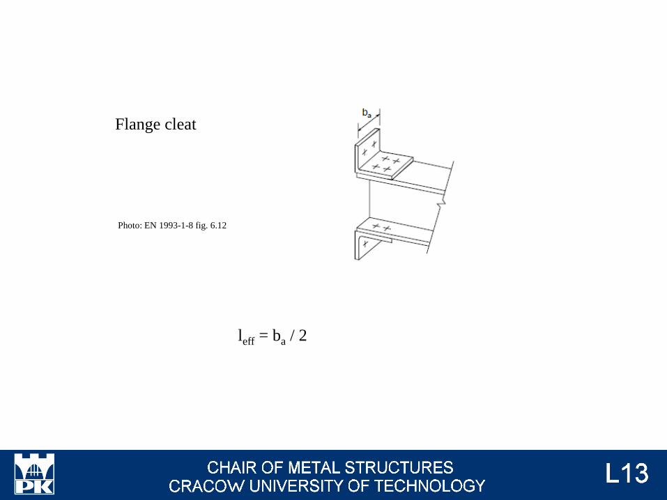
Flange cleat
leff = ba / 2
Photo: EN 1993-1-8 fig. 6.12
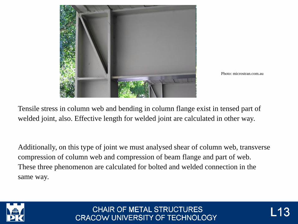
Tensile stress in column web and bending in column flange exist in tensed part of
welded joint, also. Effective length for welded joint are calculated in other way.
Additionally, on this type of joint we must analysed shear of column web, transverse
compression of column web and compression of beam flange and part of web.
These three phenomenon are calculated for bolted and welded connection in the
same way.
Photo: microstran.com.au
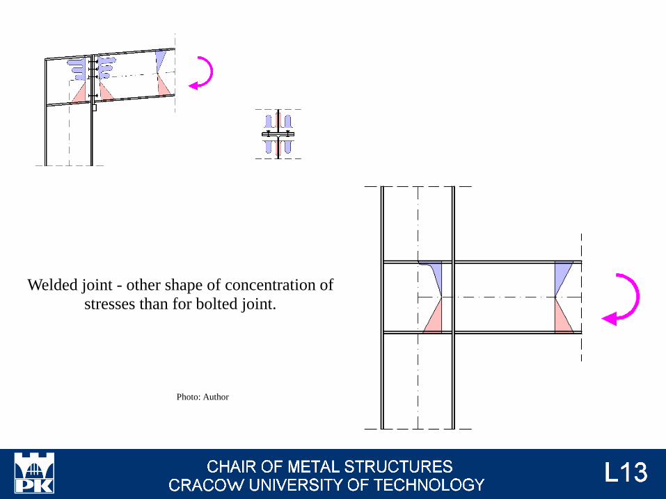
Welded joint - other shape of concentration of
stresses than for bolted joint.
Photo: Author
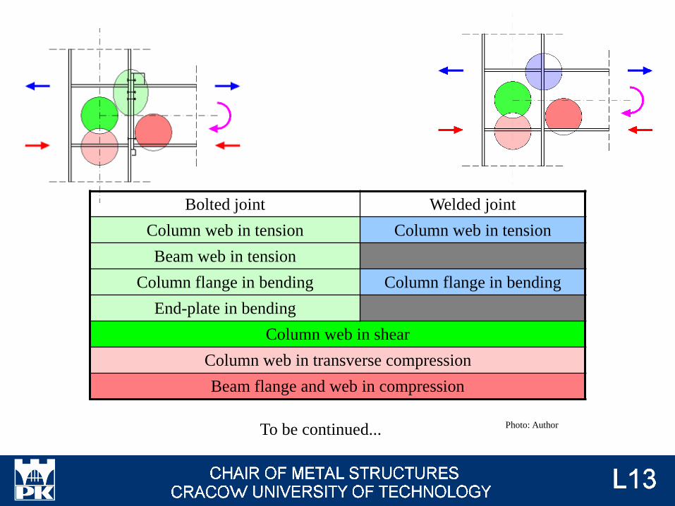
Bolted joint Welded joint
Column web in tension Column web in tension
Beam web in tension
Column flange in bending Column flange in bending
End-plate in bending
Column web in shear
Column web in transverse compression
Beam flange and web in compression
To be continued... Photo: Author
Block of information about bolts is divided between lecture #10, #11 and #12.
Examination issues for these lectures are presented at the end of lecture #12.
Examination issues
Shear (bolted) connections - połączenia (śrubowe) zakładkowe
Tension (bolted) connections - połączenia (śrubowe) doczołowe
Bearing resistance - nośność na docisk
Block tearing - rozerwanie blokowe
Slip-resistant - nośność na poślizg
Punching resistance - nośność na przeciąganie łba
Prying actions - efekt dźwigni
Cleat - nakładka z kątownika
Floor girder - ruszt
Rigging screw - śruba rzymska
Resin - żywica
Elongation length - baza wydłużalności
Grip length - grubość skleszczenia
Circular pattern - kołowy mechanizm zniszczenia
Backing plates - płytki usztywniające