Embed Size (px)
Citation preview
1
Beam-Column Connections
Dawn Lehman
John Stanton and Laura Lowes University of Washington, Seattle
Jack MoehleUniversity of California, Berkeley
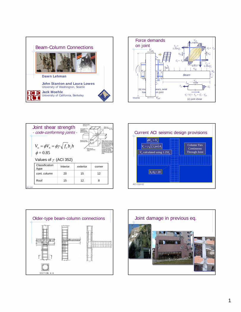
Force demands on joint
(a) moments, shears, axial loads acting on joint
(b) internal stress resultants acting on joint
Ts2 =1.25Asfy
C2 = Ts2
Ts1 = 1.25Asfy
C1 = Ts2
(c) joint shear
Vcol
Vcol
Vcol
Ts1 C2
Vu =Vj = Ts1 + C1 - Vcol
Vb1 Vb2
Beam
lnbV
wMpr
Mpr
Vp
Mpr
Vp
lc
Vcol
VcolMoehle
Classification/type
interior exterior corner
cont. column 20 15 12
Roof 15 12 8
Values of γ (ACI 352)
Joint shear strength- code-conforming joints -
hbfVV jcnu'φγφ ==
φ = 0.85
ACI 352
Current ACI seismic design provisions
Column Ties Continuous
Through Joint
hc/db> 20
Vu calculated using 1.25fy
' ( )n c jV f psi Aγ=
n uV Vφ >
ACI-318 02
Older-type beam-column connections Joint damage in previous eq.

2
-2.0 0E -01
0.00 E+ 00
PerformanceLevel
SeismicHazardLevel
+
SELECT PERFORMANCE OBJECTIVE
Seismic evaluation process
DEMAND ASSESSMENT
=
TST
VCCST
TSRCSL
Vj
VL
γ
DEMAND/PERFORMANCE RELATIONSHIPS
+
Seismic evaluation process:
Behavior
Experimental studies of older joints
Interior joint
No joint ties
Bars grooved
hc/db = 20
2/3 of full scale
P/(Agf’c) = 0.1
Study Parameters
Joint Shear StressDisplacement History
Interior joint
No joint ties
Bars grooved
hc/db = 20
2/3 of full scale
P/(Agf’c) = 0.1
Study Parameters
Joint Shear StressDisplacement History
Walker, Lehman and Stanton
-80
-60
-40
-20
0
20
40
60
80
-6 -4 -2 0 2 4 6
Col
umn
Shea
r (K
)
0.5% Drift 3% Drift
5% Drift
Damage progression
Walker, Lehman and Stanton
Standard Loading Impulsive Loading
Damage at 5% drift
Walker, Lehman and Stanton
Influence of joint shear stress
PEER-0850 PEER-4150PEER-0995Low Demand Intermediate Demand High Demand
Alire, Walker, Lehman and Stanton

3
Joint shear demandEffect on response
Join
t Stre
ss (p
si)
0
400
800
1200
1600
0 1 2 3 4 5 6
Drift Ratio (%)
Yield
Yield
• Joint “strength” closely linked to beam flexural strength• Plastic deformation capacity higher for lower joint shear
Alire, Walker, Lehman and Stanton
Joint shear “strength” Effect on damage mode and cyclic capacity
/fc’
0
0.1
0.3
0.4
0 10 20 30 40 50 60
Λ
0.2vj
Beam Hinging/Beam Bar Slip
Joint Shear Failure
Joint failure without yielding near 25.5√f’c
Failure forced into beams between 8.5√f’c and 11√f’c
Alire, Lehman and Stanton
Damage progressionexterior connections
Pantelides, 2002
Exterior jointhook detail
hook bent into joint
hook bent out of joint
Joint behaviorexterior connections
2 Clyde6 Clyde4 Clyde5 Clyde5 Pantelides6 Pantelides6 HakutoPriestley longitudinalPriestley transverse
psif
v
c
jo ,'
int
15
0 1 2 3 4 5 6 7
10
5
0
Drift, %bidirectional loading
Unreinforced Joint Strength
bhfV cj'γ=
γjointgeometry
4
6
10
8
12
FEMA 356 specifies the following:
• No new data. Probably still valid.
• Assuming bars are anchored in joint, strength limited by strength of framing members, with upper-bound of γ ≈ 15. For 15 ≥ γ ≥ 4, joint failure may occur after inelastic response. For γ ≤ 4, joint unlikely to fail.
• Assuming bars are anchored in joint, strength limited by strength of framing members, with upper bound of γ ≈ 25. For 25 ≥ γ ≥ 8, joint failure may occur after inelastic response. For γ ≤ 8, joint unlikely to fail.

4
Seismic evaluation process:
Demand/capacity assessmentEvaluation of FEMA-356 modelinterior connections
0
2
4
6
8
10
12
14
16
18
0 0.005 0.01 0.015 0.02 0.025 0.03
Joint Shear Strain
Join
t She
ar F
acto
r
FEMAPEER-14CD15-14CD30-14PADH-14PEER-22CD30-22PADH-22
Alire, Walker, Lehman and Stanton
0
20
40
60
80
100
120
1 4 7 10 13 16 19 22 25 28 31 34
Cycle Number
Perc
ent C
ontr
ibut
ion
Joint Shear
Bar Slip
Beam
Column
Specimen CD15-14
Contributions to driftinterior connections
“Joints shall be modeled as either stiff or rigid components.” (FEMA 356)
Walker, Lehman and Stanton
Simulation models: simple spring
Secant Shear Modulus of Joint
0
0.05
0.1
0.15
0.2
0.25
0.3
0.35
0 5 10 15
Shear Stress Demand (MPa)
Gse
c/G
el
CrackingYieldingSpalling
Alire, Lehman and Stanton
Suggested envelope relationinterior connections with continuous beam bars
psif
v
c
jo ,'
int 25
20
15
10
5
0
0.015
0.04 0.02
8
strength = beam strength but not to exceed
psifc ,25 '
stiffness based on effective stiffness to yield:
Moehle
0.3 0.05 cG−
Suggested envelope relationexterior connections with hooked beam bars
psif
v
c
jo ,'
int 25
20
15
10
5
0
0.010
0.02
strength = beam strength but not to exceed psifc ,12 '
stiffness based on effective stiffness to yield
0.01
connections with demand less than have beam-yield mechanisms and do not follow this model
'4 cf
axial-load stability unknown, especially under high axial loads
Moehle

5
Simulation models: simple spring
-100
-80
-60
-40
-20
0
20
40
60
80
-6.00 -4.00 -2.00 0.00 2.00 4.00 6.00
Drift (%)
Col
umn
shea
r (k)
PEER 1450 eyl
Yield of BeamLongitudinal Reinforcement
-80
-60
-40
-20
0
20
40
60
80
-4.0 -3.0 -2.0 -1.0 0.0 1.0 2.0 3.0 4.0
Drift (%)
Col
umn
shea
r (k
)
PEER 1450 Inelastic Damage Pts Rigid
InitialSpalling
Yielding
Cracking
-80
-60
-40
-20
0
20
40
60
80
-6.0 -4.0 -2.0 0.0 2.0 4.0 6.0
Drift (%)
Col
umn
shea
r (k
)
CD30 1450 Inelastic Damage Pts
Initial Spalling
Yielding
Anderson, Lehman and Stanton
Simulation models: macro-element
-1.00
-0.80
-0.60
-0.40
-0.20
0.00
0.20
0.40
0.60
0.80
1.00
-0.05 -0.04 -0.03 -0.02 -0.01 0 0.01 0.02 0.03 0.04 0.05
Joint Shear Strain (radians)
Join
t She
ar S
tres
s (k
si)
CD15-1450 ModelAnderson, Lehmanand Stanton
Seismic Evaluation Process:
Performance Models
=
TST
VCCST
TSRCSL
Vj
VL
γ
DEMAND/PERFORMANCE RELATIONSHIPS
+0
5
10
15
20
25
30
0 0.01 0.02 0.03 0.04 0.05 0.06
plastic drift angle
psif
v
c
jo ,'
int
Note: the plastic drift angle includes inelastic deformations of the beams
InteriorExterior
Plastic drift capacity(20% loss in lateral strength)
Moehle
Methods of repair (MOR)
Spalling >80% of jt. area
Spalling <80% of jt. area
crack width ≥0.02 in.
crack width < 0.02 in
Repair finishes
MOR1
Epoxy Injection
MOR2
Replace ConcretePatching
MOR4MOR3
Pagni and Lowes
Fragility relations for interior joints
0.0 1.0 2.0 3.0 4.0 5.0 6.000.10.20.30.40.50.60.70.80.91
Drift (%)
MOR 0MOR 1MOR 2MOR 3MOR 4
0.0 1.0 2.0 3.0 4.0 5.0 6.000.10.20.30.40.50.60.70.80.91
Drift (%)
MOR 0MOR 1MOR 2MOR 3MOR 4
MOR 0MOR 1MOR 2MOR 3MOR 4
MOR 0MOR 1MOR 2MOR 3MOR 4Pr
obab
ility
of R
equi
ring
a M
OR
Cosmetic repairEpoxy injectionPatchingReplace concreteReplace joint
Cosmetic repairEpoxy injectionPatchingReplace concreteReplace joint
Pagni and Lowes
6
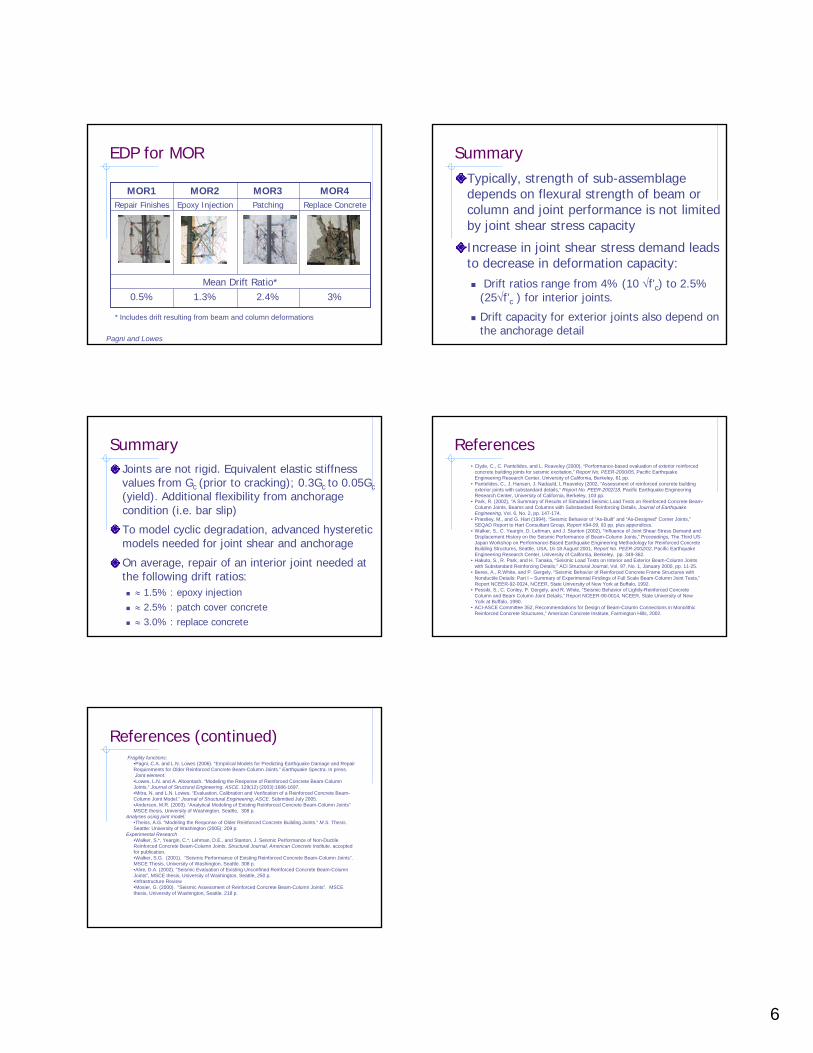
EDP for MOR
Mean Drift Ratio*0.5%
Repair Finishes
MOR1
1.3%
Epoxy Injection
MOR2
3%2.4%
Replace ConcretePatching
MOR4MOR3
* Includes drift resulting from beam and column deformations
Pagni and Lowes
SummaryTypically, strength of sub-assemblage depends on flexural strength of beam or column and joint performance is not limited by joint shear stress capacity
Increase in joint shear stress demand leads to decrease in deformation capacity:
Drift ratios range from 4% (10 √f’c) to 2.5% (25√f’c ) for interior joints.
Drift capacity for exterior joints also depend on the anchorage detail
SummaryJoints are not rigid. Equivalent elastic stiffness values from Gc (prior to cracking); 0.3Gc to 0.05Gc (yield). Additional flexibility from anchorage condition (i.e. bar slip)
To model cyclic degradation, advanced hysteretic models needed for joint shear and anchorage
On average, repair of an interior joint needed at the following drift ratios:
≈ 1.5% : epoxy injection≈ 2.5% : patch cover concrete≈ 3.0% : replace concrete
References• Clyde, C., C. Pantelides, and L. Reaveley (2000), “Performance-based evaluation of exterior reinforced
concrete building joints for seismic excitation,” Report No. PEER-2000/05, Pacific Earthquake Engineering Research Center, University of California, Berkeley, 61 pp.
• Pantelides, C., J. Hansen, J. Nadauld, L Reaveley (2002, “Assessment of reinforced concrete building exterior joints with substandard details,” Report No. PEER-2002/18, Pacific Earthquake Engineering Research Center, University of California, Berkeley, 103 pp.
• Park, R. (2002), "A Summary of Results of Simulated Seismic Load Tests on Reinforced Concrete Beam-Column Joints, Beams and Columns with Substandard Reinforcing Details, Journal of Earthquake Engineering, Vol. 6, No. 2, pp. 147-174.
• Priestley, M., and G. Hart (1994), “Seismic Behavior of “As-Built” and “As-Designed” Corner Joints,”SEQAD Report to Hart Consultant Group, Report #94-09, 93 pp. plus appendices.
• Walker, S., C. Yeargin, D. Lehman, and J. Stanton (2002), “Influence of Joint Shear Stress Demand and Displacement History on the Seismic Performance of Beam-Column Joints,” Proceedings, The Third US-Japan Workshop on Performance-Based Earthquake Engineering Methodology for Reinforced ConcreteBuilding Structures, Seattle, USA, 16-18 August 2001, Report No. PEER-2002/02, Pacific Earthquake Engineering Research Center, University of California, Berkeley, pp. 349-362.
• Hakuto, S., R. Park, and H. Tanaka, “Seismic Load Tests on Interior and Exterior Beam-Column Joints with Substandard Reinforcing Details,” ACI Structural Journal, Vol. 97, No. 1, January 2000, pp. 11-25.
• Beres, A., R.White, and P. Gergely, “Seismic Behavior of Reinforced Concrete Frame Structures with Nonductile Details: Part I – Summary of Experimental Findings of Full Scale Beam-Column Joint Tests,”Report NCEER-92-0024, NCEER, State University of New York at Buffalo, 1992.
• Pessiki, S., C. Conley, P. Gergely, and R. White, “Seismic Behavior of Lightly-Reinforced Concrete Column and Beam Column Joint Details,” Report NCEER-90-0014, NCEER, State University of New York at Buffalo, 1990.
• ACI-ASCE Committee 352, Recommendations for Design of Beam-Column Connections in Monolithic Reinforced Concrete Structures,” American Concrete Institute, Farmington Hills, 2002.
References (continued)Fragility functions:
•Pagni, C.A. and L.N. Lowes (2006). “Empirical Models for Predicting Earthquake Damage and Repair Requirements for Older Reinforced Concrete Beam-Column Joints.” Earthquake Spectra. In press.Joint element:•Lowes, L.N. and A. Altoontash. “Modeling the Response of Reinforced Concrete Beam-Column Joints.” Journal of Structural Engineering, ASCE. 129(12) (2003):1686-1697.•Mitra, N. and L.N. Lowes. “Evaluation, Calibration and Verification of a Reinforced Concrete Beam-Column Joint Model.” Journal of Structural Engineering, ASCE. Submitted July 2005. •Anderson, M.R. (2003). “Analytical Modeling of Existing Reinforced Concrete Beam-Column Joints” MSCE thesis, University of Washington, Seattle, 308 p.
Analyses using joint model:•Theiss, A.G. “Modeling the Response of Older Reinforced Concrete Building Joints.” M.S. Thesis. Seattle: University of Washington (2005): 209 p.
Experimental Research•Walker, S.*, Yeargin, C.*, Lehman, D.E., and Stanton, J. Seismic Performance of Non-Ductile Reinforced Concrete Beam-Column Joints, Structural Journal, American Concrete Institute, accepted for publication.•Walker, S.G. (2001). “Seismic Performance of Existing Reinforced Concrete Beam-Column Joints”. MSCE Thesis, University of Washington, Seattle. 308 p.•Alire, D.A. (2002). "Seismic Evaluation of Existing Unconfined Reinforced Concrete Beam-Column Joints", MSCE thesis, University of Washington, Seattle, 250 p.•Infrastructure Review•Mosier, G. (2000). “Seismic Assessment of Reinforced Concrete Beam-Column Joints”. MSCE thesis, University of Washington, Seattle. 218 p.