Embed Size (px)
Citation preview

Supplementary Information
Scalable Simultaneous Activation and Separation of
Metal-Organic Frameworks
Marta Rubio-Martinez, Thomas Leong, Pablo Juliano, Trevor D. Hadley, Michael P. Batten, Anastasios Polyzos, Kok-Seng Lim and Matthew R. Hill
Electronic Supplementary Material (ESI) for RSC Advances.This journal is © The Royal Society of Chemistry 2016

S1. General description of the continuous flow MOF process
S1.a. The different stages of the continuous flow process for MOFs production: synthesis, washing, separation and drying.
S1.b. Continuous flow MOF macroscale reactor
Continuous flow scale-up synthesis was performed in a Salamander Flow Reactor (Cambridge Reactor
Design Ltd., Cottenham, UK) as previously detailed by Micic et. al.1 . Briefly, it consists of a serpentine
stainless steel tube (8 mm o.d., 6 mm i.d., 108 mL volume) and a thermostatically-controlled electrical
heating system (ambient to 150 °C). An inline back-pressure regulator, situated at the outlet of the
reactor, allows fine tuning of the reactor pressure (up to 20 bar). Static mixer units are placed within the
linear sections of the reactor tubing to promote tubulent mixing and efficient heat transfer. Twin Gilson
305 dual piston pumps, (flow rates between 0.5 mL/min and 50 mL/min) provide the solvent and reagent
feeds for the reactor system. Figure S1 shows a representative flow reactor configuration for MOF
processing.
In a typical reaction, two separate solutions of the precursors are pumped through a T-type static mixer to
promote diffusion mixing of the reagent input streams. The combined reagent streams are then directed
into the heated reactor zone of the Salamander Flow Reactor for a predetermined residence time. On
exiting the reactor, the stream is cooled in a external heat sink unit, based on a coiled tube in a water bath.
Then the stream passes through a back-pressure regulator, and is collected for the next process steps.
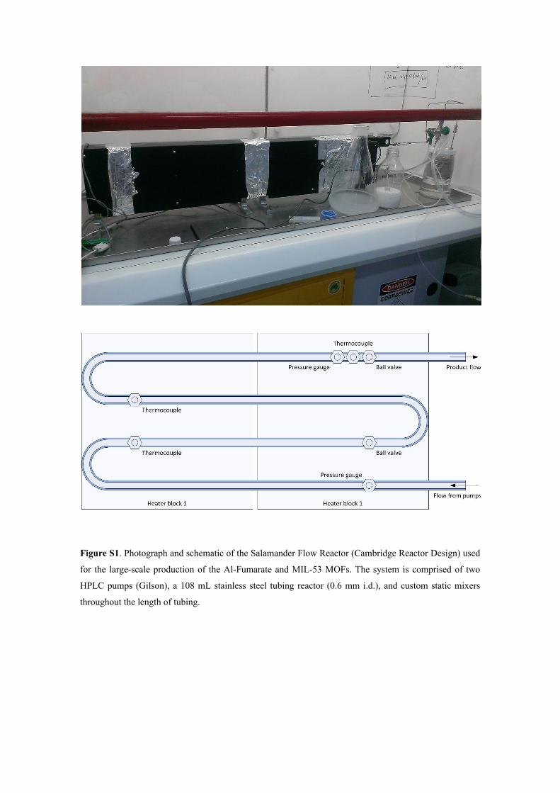
Figure S1. Photograph and schematic of the Salamander Flow Reactor (Cambridge Reactor Design) used
for the large-scale production of the Al-Fumarate and MIL-53 MOFs. The system is comprised of two
HPLC pumps (Gilson), a 108 mL stainless steel tubing reactor (0.6 mm i.d.), and custom static mixers
throughout the length of tubing.
S2. Synthesis of Al-Fumarate and MIL-53 using Salamander flow reactor
S2.a. Synthesis of Al-Fumarate
The general procedure described in S1.b. was employed. An aqueous solution of 0.35M Al2(SO4)3 18H2O
and an aqueous solution of 0.7M of fumaric acid and 2M of NaOH solution were mixed under continuous
flow conditions and heated in a tubular reactor. The synthesis was conducted at 65 ºC using a total flow
rate of 90 mL•min-1, giving a total residence time of 1.2 min. The material was washed three times with
fresh water and twice with ethanol and dried in vacuum (500 mbar) for 8 hours at 40 ºC. Yield: 100%.
S2.b. Synthesis of MIL-53 (Al)
The general procedure described in S1.b. was employed. An aqueous solution of 0.08M Al(NO)3 and an
aqueous solution of 0.08M of terephthalic acid and 0.24M of NaOH solution were mixed under
continuous flow conditions and heated in a tubular reactor. The synthesis was conducted at 140 ºC using a
total flow rate of 90 mL•min-1, giving a total residence time of 1.2 min. The material was washed three
times with fresh water and twice with ethanol and dried in vacuum (500 mbar) for 8 hours at 40 ºC.
Yield: 83%.
S2.c. Continuous flow MOF: separation and washing steps using megasonics
The separation of the MOF was carried out in a transparent Perspex acrylic chamber with a capacity of
6 L, in where the transducer is fixed in vertical position. All trials were conducted utilizing submersible
stainless steel transducer plates (Sonosys Ultraschallsysteme GmbH, Neuenbuerg, Germany) operating at
2 MHz. The optimization of the system was performed in a stainless steel 1L container.
Each experiment consisted of filling the acoustic reactor with a diluted MOF solution (50% in water) and
immediately sonicating for 10 min. A control system, where no ultrasound was applied, was
simultaneously filled with a portion of the same MOFs solution to observe the differences. In all
experiments the temperature increased up to 10 ̊C, caused by acoustic energy dissipation, therefore an ice
bath is used during the experiments.
Before and after the application of ultrasound, 10 mL samples were removed to measure the ζ-potential of
the MOFs. Using megasonics the MOF product was washed three times with fresh water and twice with
EtOH.
S3. Characterization
The scanning electron microscopy (SEM) images were collected on a Quanta 400 FEG ESEM (FEI) at
acceleration voltage of 0.2-30 kV. Infrared (IR) spectra were recorded on a Tensor 27FTIR
spectrophotometer (Bruker). The X-ray powder diffraction (XRPD) measurements were performed with
an X’Pert Pro MPD diffractometer (Panalytical) over a 2θ range of 5º to 45º. The thermogravimetric
analysis (TGA) was performed on a Perkin-Elmer STA-600 under a constant flow of N2 at a temperature
increase rate of 5 ºC/min. Zeta potential measurements were performed on a NanoZs Zetasizer from
MALVERN whereas the Turbiscan measurements were performed with the MA 2000 (Formulaction,
Toulouse, France). Gas adsorption isotherms for pressures in the range 0 – 120 kPa were measured by a
volumetric approach using a Micrometrics ASAP 2420 instrument. All the samples were transferred to
pre-dried and weighed analysis tubes and sealed with Transcal stoppers. Al-Fumarate and MIL-53 were
evacuated and activated under dynamic vacuum at 10-6 Torr at 140 ºC for 8 hours. Ultra-high purity N2, CH4, H2 and CO2 gases were used for the experiments. N2 and H2 adsorption and desorption
measurements were conducted at 77K. Surface area measurements were performed on N2 isotherms at
77K using the Brunauer-Emmer-Teller (BET) model with adsorption values increasing range of 0.005 to
0.2 relative pressures while the CH4 adsorption and CO2 adsorption measurements were done at 273 and
298 K, respectively.
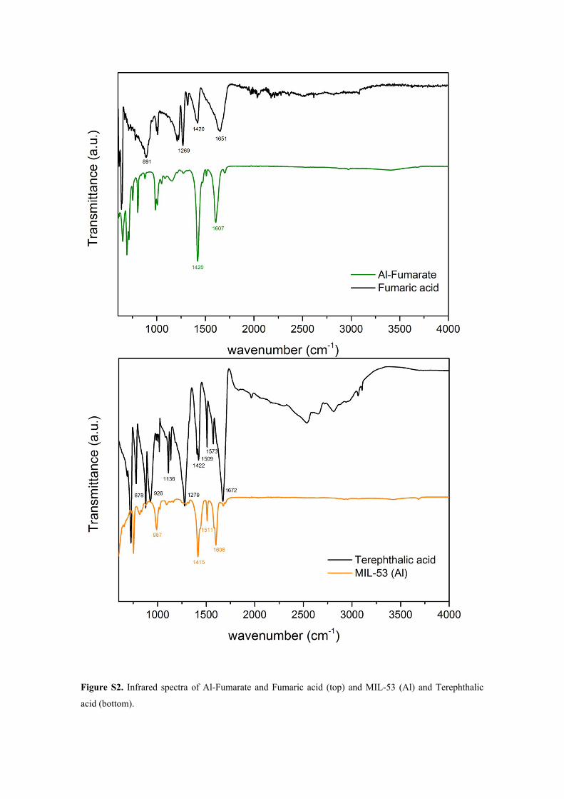
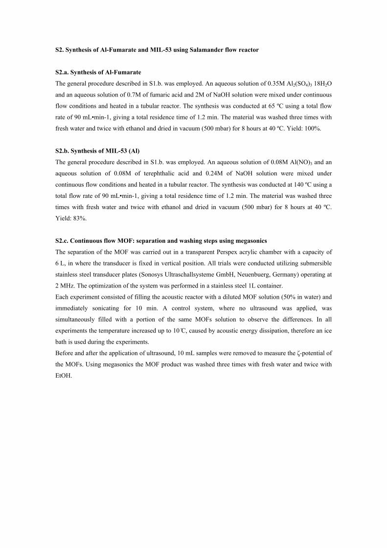
Figure S2. Infrared spectra of Al-Fumarate and Fumaric acid (top) and MIL-53 (Al) and Terephthalic
acid (bottom).
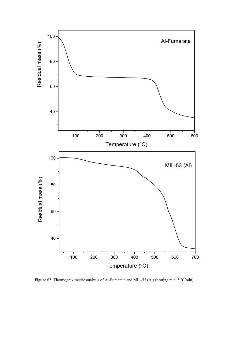
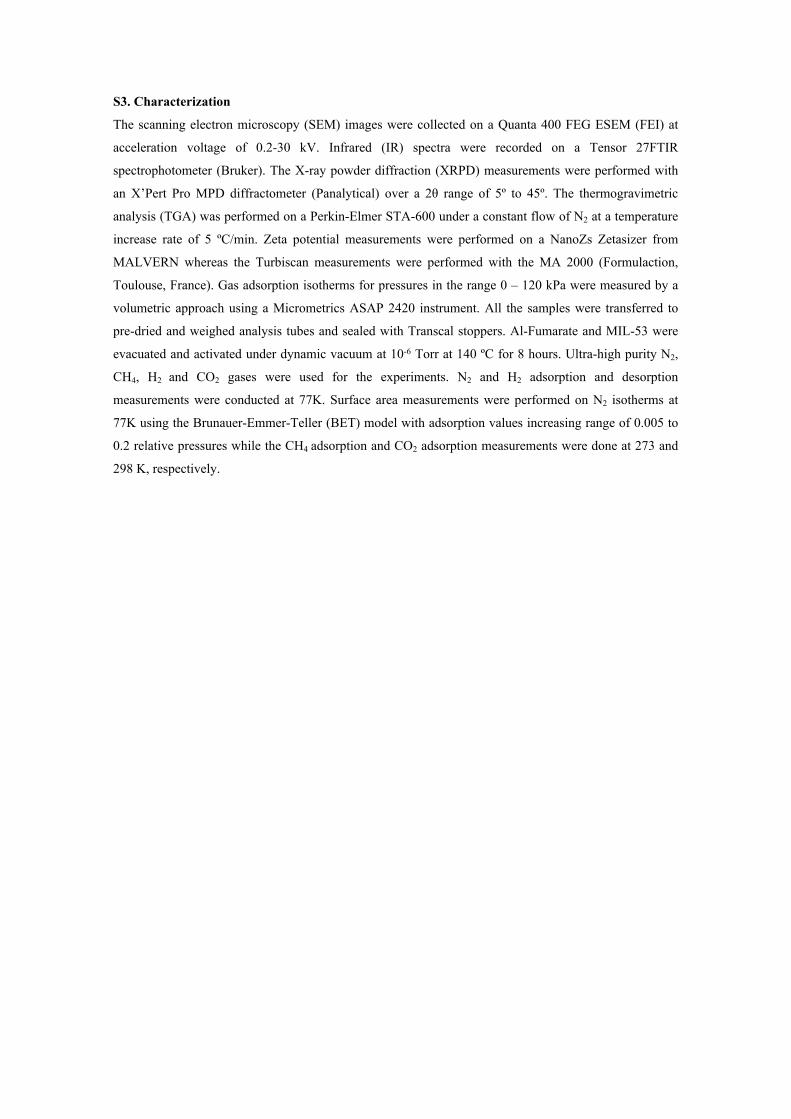
Figure S3. Thermogravimetric analysis of Al-Fumarate and MIL-53 (Al) (heating rate: 5 ºC/min).
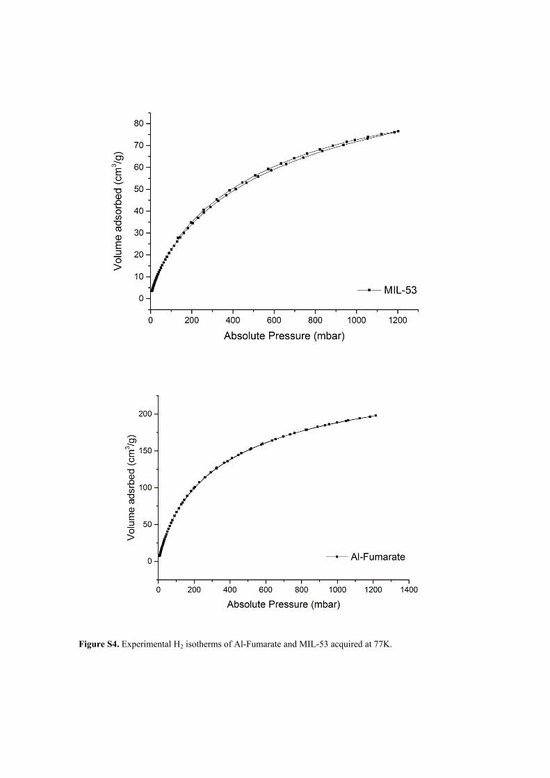
Figure S4. Experimental H2 isotherms of Al-Fumarate and MIL-53 acquired at 77K.
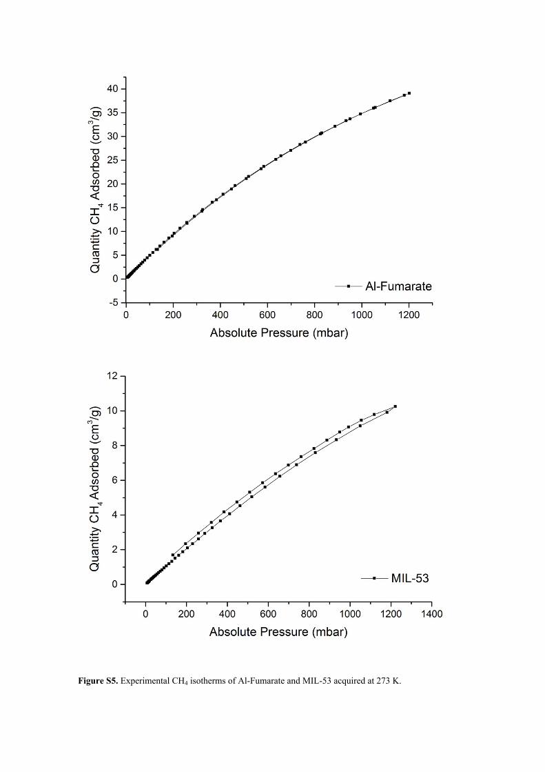
Figure S5. Experimental CH4 isotherms of Al-Fumarate and MIL-53 acquired at 273 K.

Figure S6. Experimental CO2 isotherms of Al-Fumarate and MIL-53 acquired at 273 and 298 K.
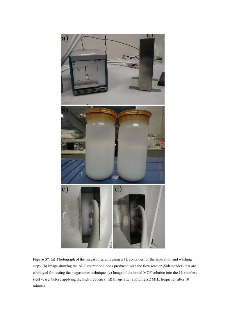
Figure S7. (a) Photograph of the megasonics unit using a 1L container for the separation and washing
steps. (b) Image showing the Al-Fumarate solutions produced with the flow reactor (Salamander) that are
employed for testing the megasonics technique. (c) Image of the initial MOF solution into the 1L stainless
steel vessel before applying the high frequency. (d) Image after applying a 2 MHz frequency after 10
minutes.
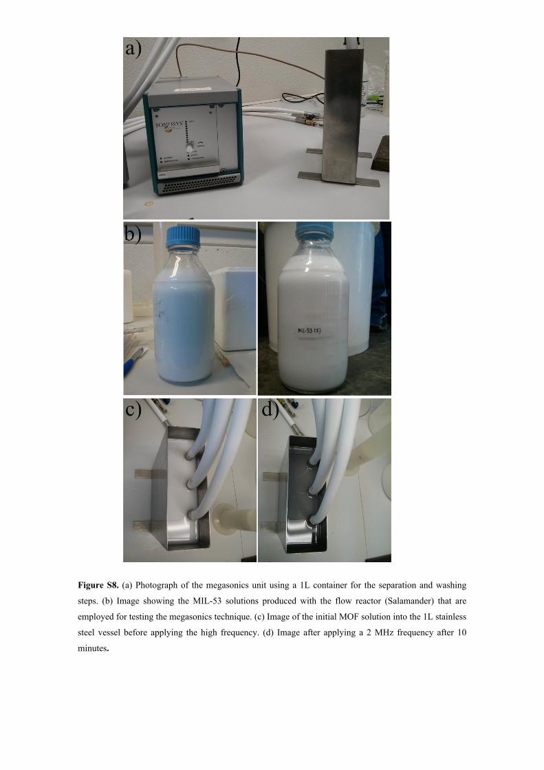
Figure S8. (a) Photograph of the megasonics unit using a 1L container for the separation and washing
steps. (b) Image showing the MIL-53 solutions produced with the flow reactor (Salamander) that are
employed for testing the megasonics technique. (c) Image of the initial MOF solution into the 1L stainless
steel vessel before applying the high frequency. (d) Image after applying a 2 MHz frequency after 10
minutes.
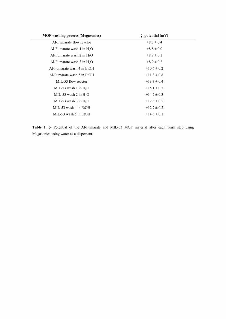
MOF washing process (Megasonics) ζ- potential (mV)
Al-Fumarate flow reactor +8.3 ± 0.4
Al-Fumarate wash 1 in H2O +8.8 ± 0.0
Al-Fumarate wash 2 in H2O +8.8 ± 0.1
Al-Fumarate wash 3 in H2O +8.9 ± 0.2
Al-Fumarate wash 4 in EtOH +10.6 ± 0.2
Al-Fumarate wash 5 in EtOH +11.3 ± 0.8
MIL-53 flow reactor +13.3 ± 0.4
MIL-53 wash 1 in H2O +15.1 ± 0.5
MIL-53 wash 2 in H2O +14.7 ± 0.3
MIL-53 wash 3 in H2O +12.6 ± 0.5
MIL-53 wash 4 in EtOH +12.7 ± 0.2
MIL-53 wash 5 in EtOH +14.6 ± 0.1
Table 1. ζ- Potential of the Al-Fumarate and MIL-53 MOF material after each wash step using
Megasonics using water as a dispersant.
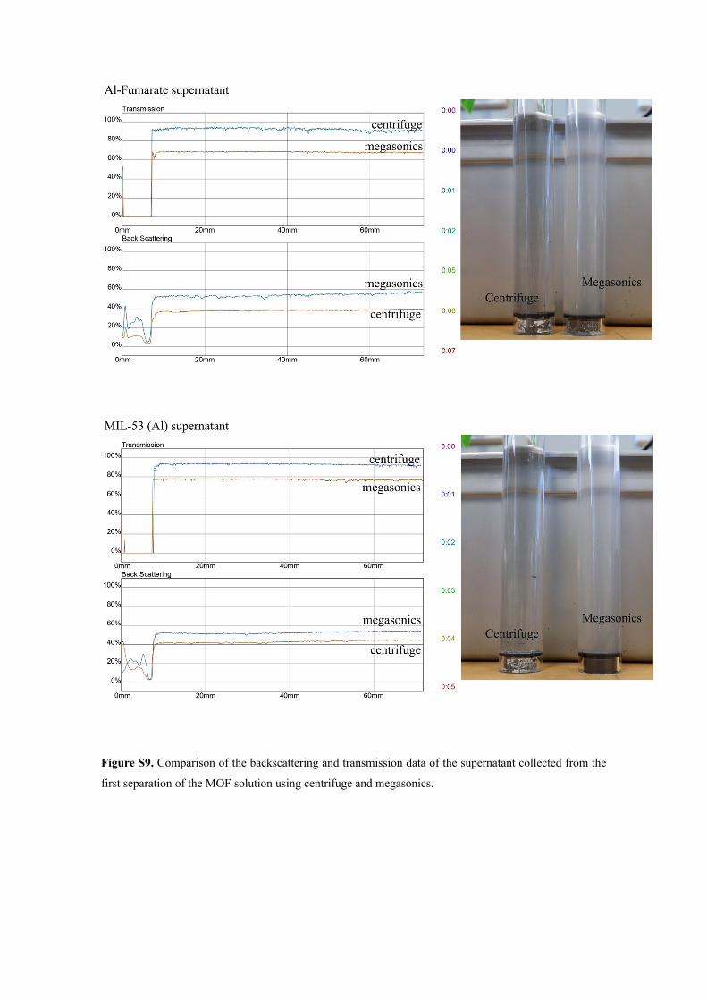
Figure S9. Comparison of the backscattering and transmission data of the supernatant collected from the
first separation of the MOF solution using centrifuge and megasonics.
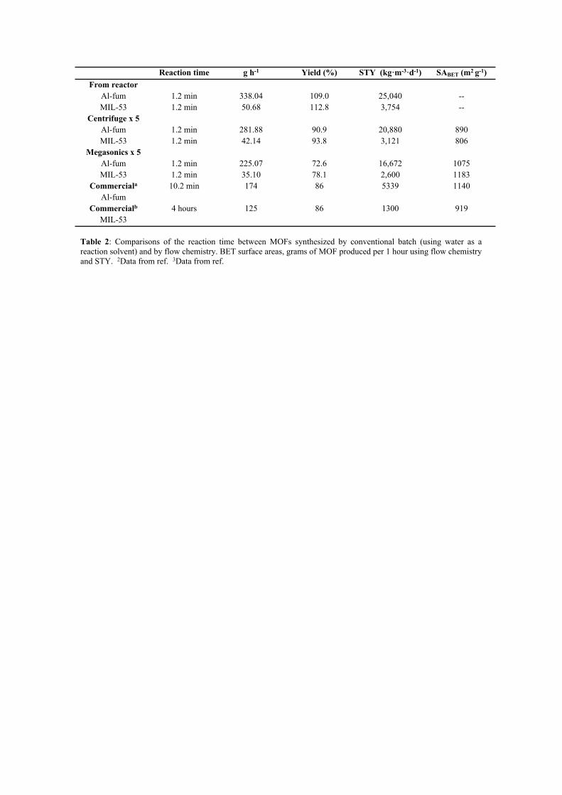
Reaction time g h-1 Yield (%) STY (kg·m-3·d-1) SABET (m2 g-1)From reactor
Al-fumMIL-53
1.2 min1.2 min
338.04 50.68
109.0 112.8
25,0403,754
----
Centrifuge x 5Al-fumMIL-53
1.2 min1.2 min
281.8842.14
90.993.8
20,8803,121
890806
Megasonics x 5Al-fumMIL-53
1.2 min1.2 min
225.0735.10
72.678.1
16,6722,600
10751183
Commerciala
Al-fum10.2 min 174 86 5339 1140
Commercialb
MIL-534 hours 125 86 1300 919
Table 2: Comparisons of the reaction time between MOFs synthesized by conventional batch (using water as a reaction solvent) and by flow chemistry. BET surface areas, grams of MOF produced per 1 hour using flow chemistry and STY. 2Data from ref. 3Data from ref.
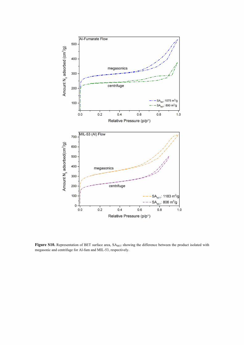
Figure S10. Representation of BET surface area, SABET showing the difference between the product isolated with megasonic and centrifuge for Al-fum and MIL-53, respectively.

References
1. Micic, N.; Young, A.; Rosselgong, J.; Hornung, C.H. Scale-up of the Reversible Addition-
Fragmentation Chain Transfer (RAFT) Polymerization Using Continuous Flow Processing.
Processes 2014, 2, 58-70.2. http://mofapps.com/Order.html
3. http://www.sigmaaldrich.com/catalog/product/aldrich/688738?lang=en®ion=AU