Embed Size (px)
Citation preview
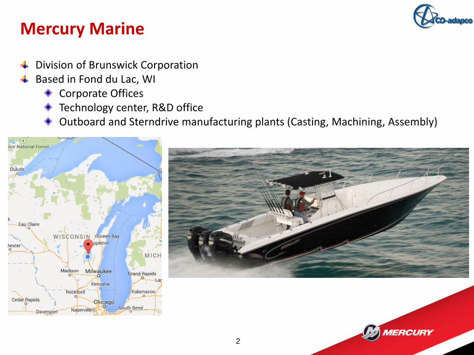
Mercury Marine
2
Division of Brunswick CorporationBased in Fond du Lac, WI
Corporate OfficesTechnology center, R&D officeOutboard and Sterndrive manufacturing plants (Casting, Machining, Assembly)
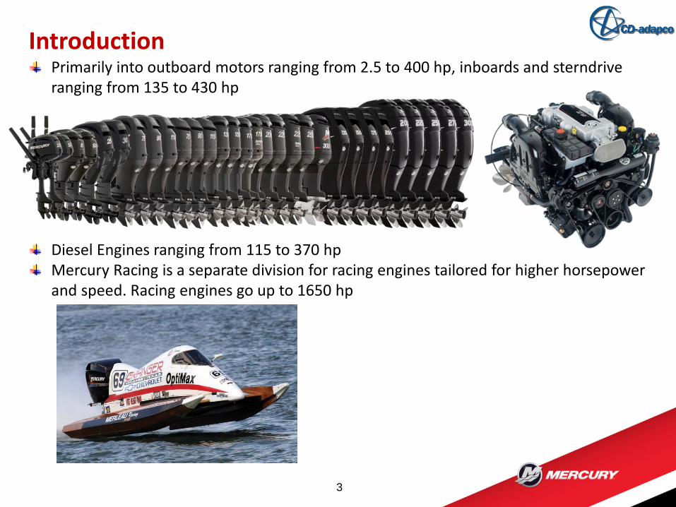
Introduction
3
Primarily into outboard motors ranging from 2.5 to 400 hp, inboards and sterndrive ranging from 135 to 430 hp
Diesel Engines ranging from 115 to 370 hpMercury Racing is a separate division for racing engines tailored for higher horsepower and speed. Racing engines go up to 1650 hp
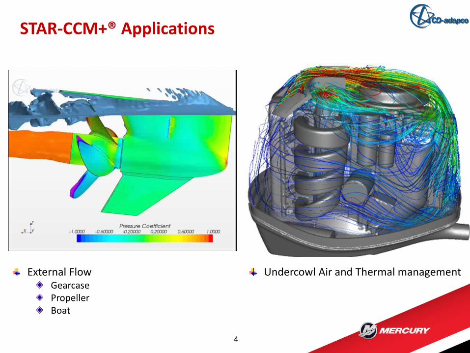
STAR-CCM+® Applications
4
External FlowGearcasePropellerBoat
Undercowl Air and Thermal management
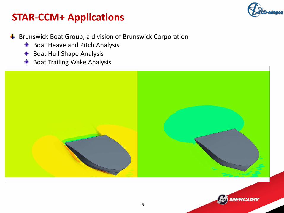
STAR-CCM+ Applications
5
Brunswick Boat Group, a division of Brunswick CorporationBoat Heave and Pitch Analysis Boat Hull Shape AnalysisBoat Trailing Wake Analysis
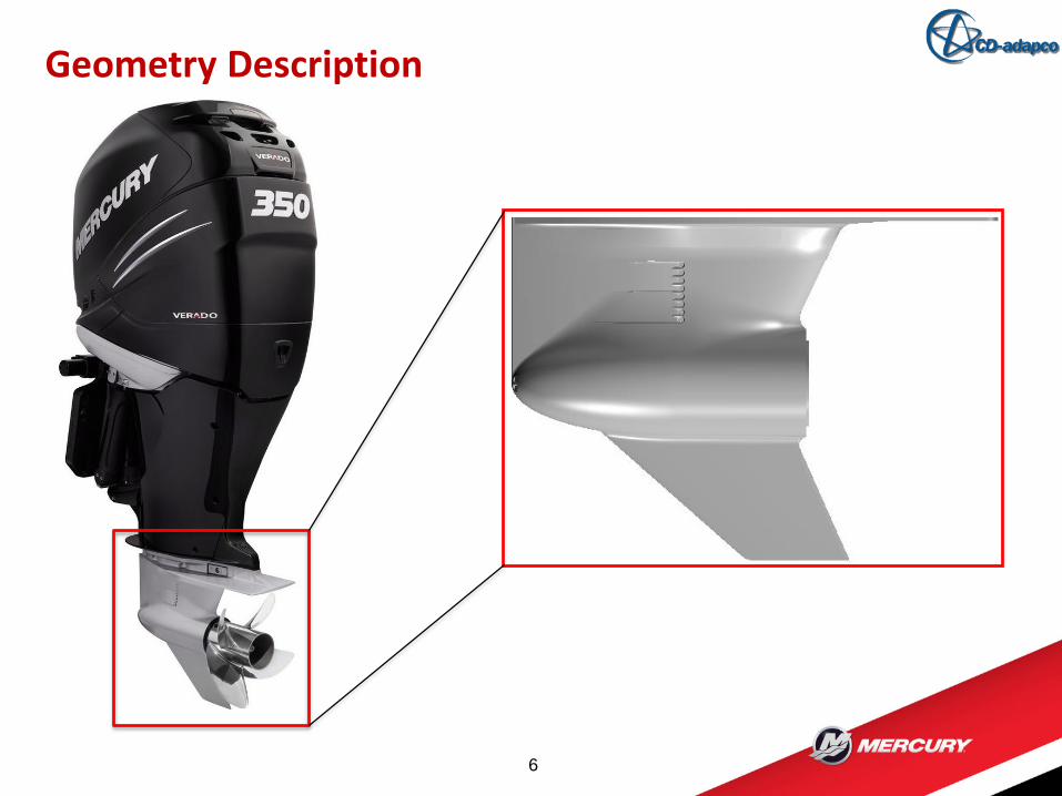
Geometry Description
6
Geometry Description
7
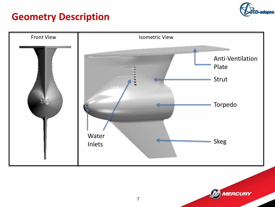
Front View Isometric View
Strut
Torpedo
Skeg
Anti-Ventilation Plate
Water Inlets
Aim
8
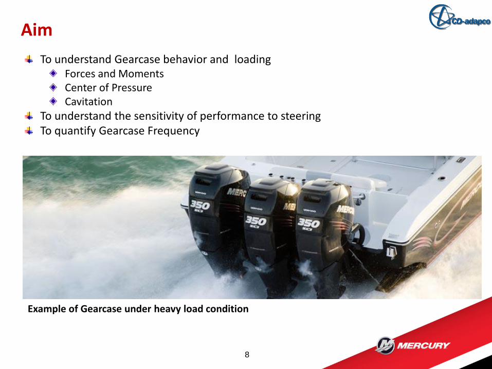
To understand Gearcase behavior and loadingForces and MomentsCenter of PressureCavitation
To understand the sensitivity of performance to steeringTo quantify Gearcase Frequency
Example of Gearcase under heavy load condition
Aim
9
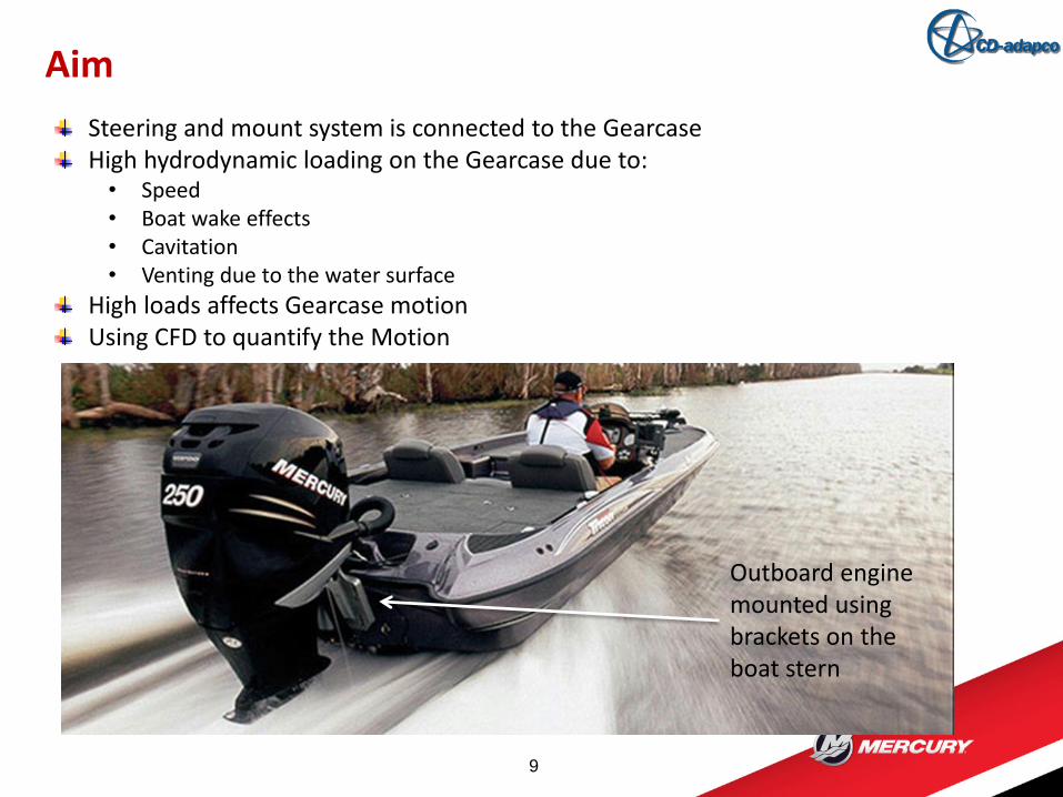
Steering and mount system is connected to the GearcaseHigh hydrodynamic loading on the Gearcase due to:• Speed• Boat wake effects• Cavitation• Venting due to the water surface
High loads affects Gearcase motionUsing CFD to quantify the Motion
Outboard engine mounted using brackets on the boat stern
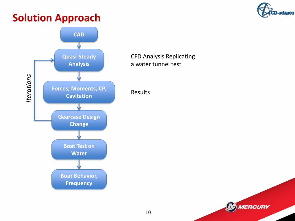
Solution Approach
10
CAD
Quasi-Steady Analysis
Forces, Moments, CP, Cavitation
Gearcase Design Change
Boat Test on Water
Boat Behavior, Frequency
CFD Analysis Replicating a water tunnel test
Results
Iter
ati
on
s
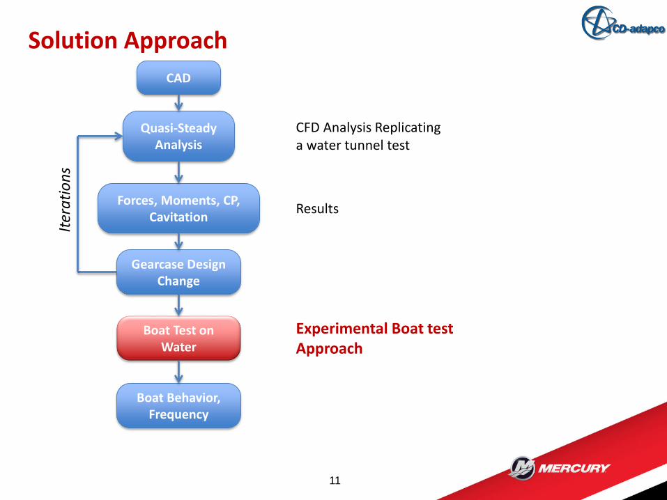
Solution Approach
11
CAD
Quasi-Steady Analysis
Forces, Moments, CP, Cavitation
Gearcase Design Change
Boat Test on Water
Boat Behavior, Frequency
CFD Analysis Replicating a water tunnel test
Results
Iter
ati
on
s
Experimental Boat test Approach
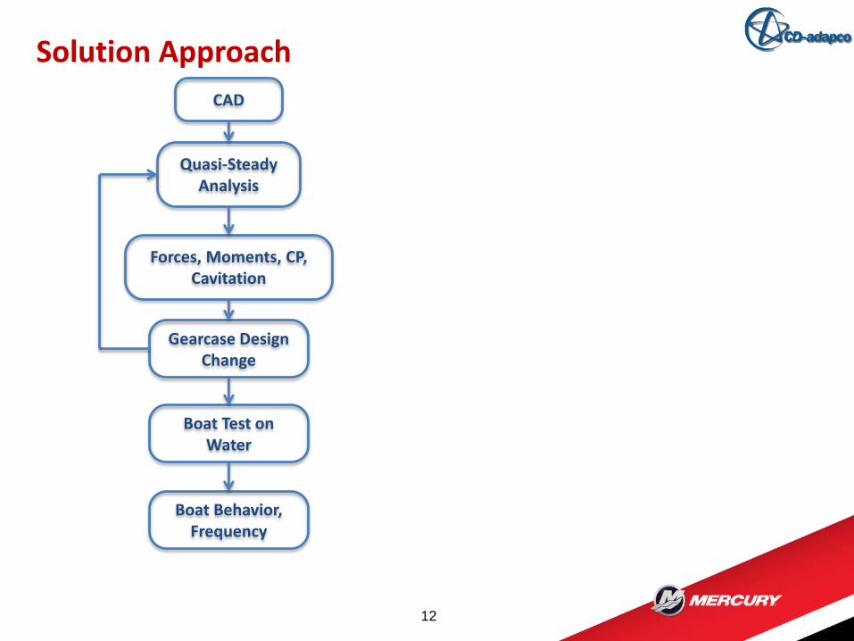
Solution Approach
12
CAD
Quasi-Steady Analysis
Forces, Moments, CP, Cavitation
Gearcase Design Change
Boat Test on Water
Boat Behavior, Frequency
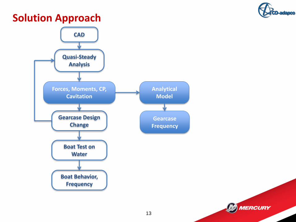
Solution Approach
13
CAD
Quasi-Steady Analysis
Forces, Moments, CP, Cavitation
Gearcase Design Change
Boat Test on Water
Boat Behavior, Frequency
Analytical Model
Gearcase Frequency
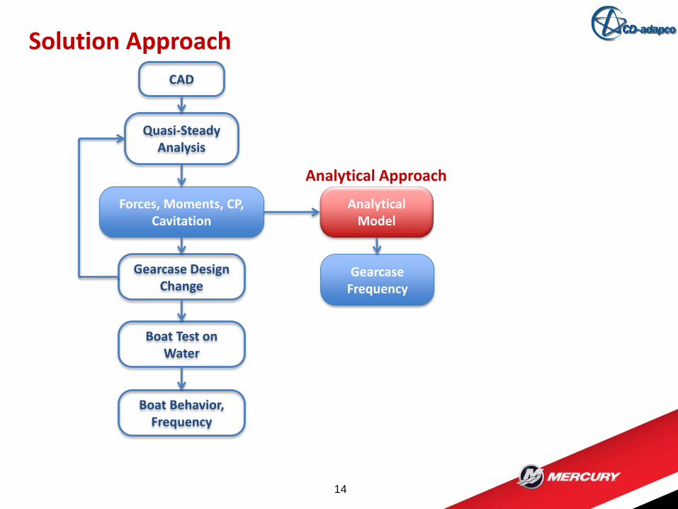
Solution Approach
14
CAD
Quasi-Steady Analysis
Forces, Moments, CP, Cavitation
Gearcase Design Change
Boat Test on Water
Boat Behavior, Frequency
Analytical Model
Gearcase Frequency
Analytical Approach
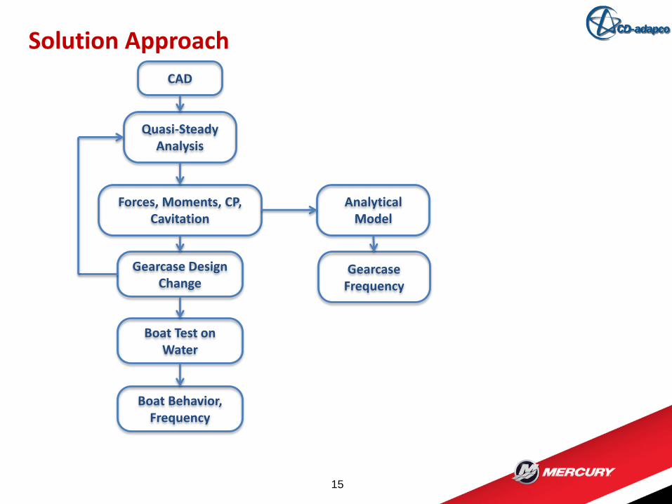
Solution Approach
15
CAD
Quasi-Steady Analysis
Forces, Moments, CP, Cavitation
Gearcase Design Change
Boat Test on Water
Boat Behavior, Frequency
Analytical Model
Gearcase Frequency
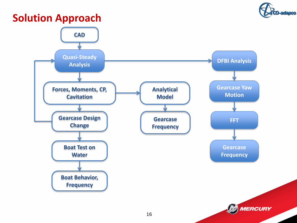
Solution Approach
16
CAD
Quasi-Steady Analysis
Forces, Moments, CP, Cavitation
Gearcase Design Change
Boat Test on Water
Boat Behavior, Frequency
Analytical Model
Gearcase Frequency
DFBI Analysis
Gearcase Yaw Motion
FFT
Gearcase Frequency
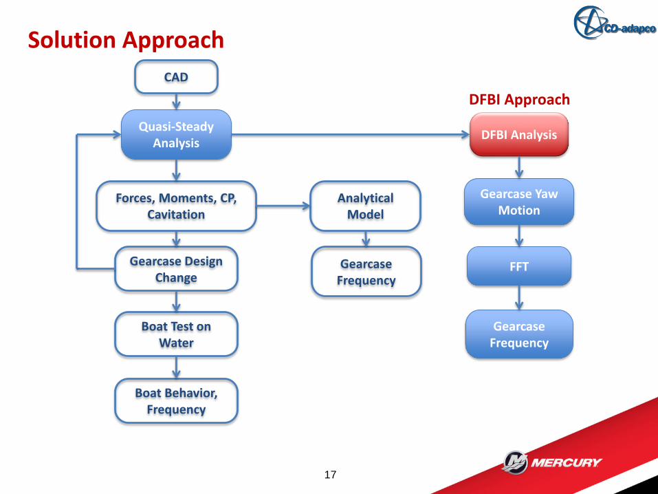
Solution Approach
17
CAD
Quasi-Steady Analysis
Forces, Moments, CP, Cavitation
Gearcase Design Change
Boat Test on Water
Boat Behavior, Frequency
Analytical Model
Gearcase Frequency
DFBI Analysis
Gearcase Yaw Motion
FFT
Gearcase Frequency
DFBI Approach
Solution Approach
18
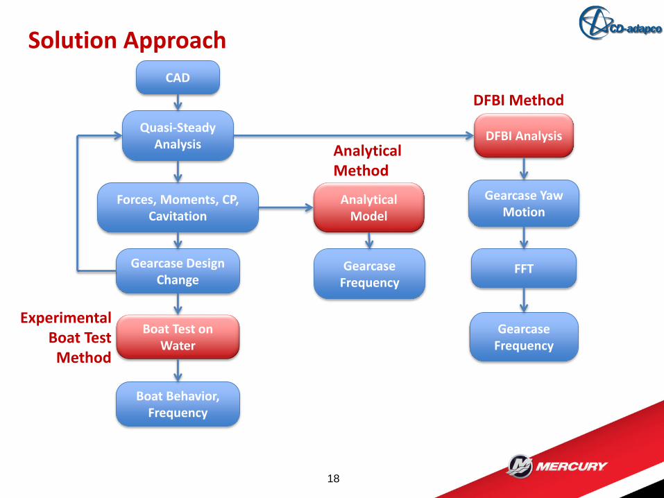
CAD
Quasi-Steady Analysis
Forces, Moments, CP, Cavitation
Gearcase Design Change
Boat Test on Water
Boat Behavior, Frequency
Analytical Model
Gearcase Frequency
DFBI Analysis
Gearcase Yaw Motion
FFT
Gearcase Frequency
DFBI Method
Analytical Method
Experimental Boat Test
Method
Solution Approach
19
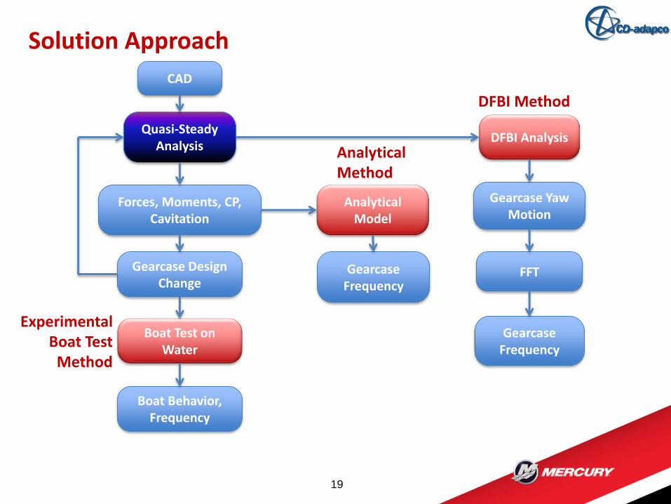
CAD
Quasi-Steady Analysis
Forces, Moments, CP, Cavitation
Gearcase Design Change
Boat Test on Water
Boat Behavior, Frequency
Analytical Model
Gearcase Frequency
DFBI Analysis
Gearcase Yaw Motion
FFT
Gearcase Frequency
DFBI Method
Analytical Method
Experimental Boat Test
Method
Quasi-Steady Analysis Formulation
20
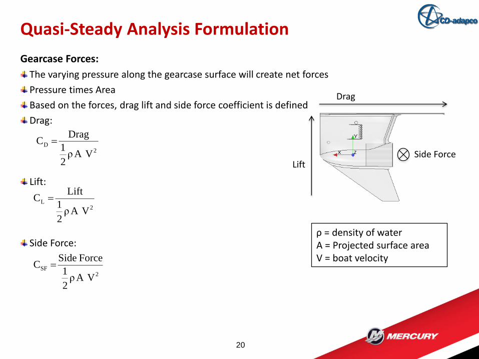
Gearcase Forces:
The varying pressure along the gearcase surface will create net forces
Pressure times Area
Based on the forces, drag lift and side force coefficient is defined
Drag:
Lift:
Side Force:
Drag
LiftSide Force2
D
VAρ2
1
DragC
ρ = density of water A = Projected surface areaV = boat velocity
2L
VAρ2
1
LiftC
2SF
VAρ2
1
Force SideC
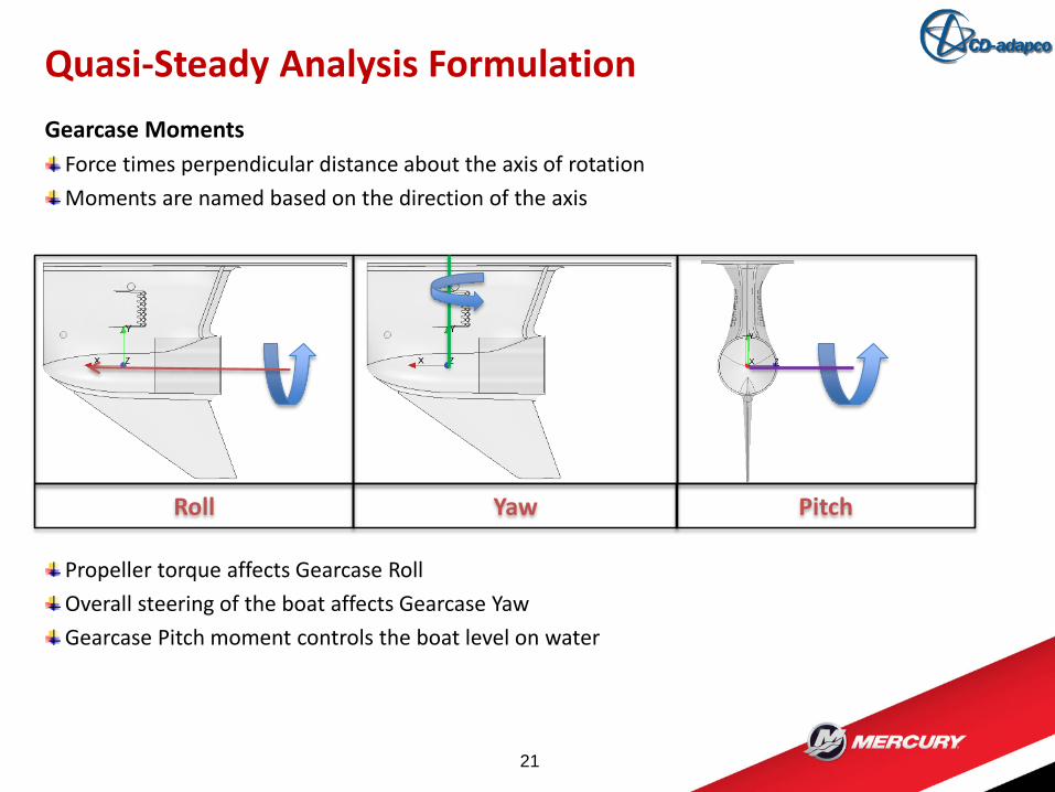
Gearcase Moments
Force times perpendicular distance about the axis of rotation
Moments are named based on the direction of the axis
Propeller torque affects Gearcase Roll
Overall steering of the boat affects Gearcase Yaw
Gearcase Pitch moment controls the boat level on water
Quasi-Steady Analysis Formulation
21
Roll Yaw Pitch
Quasi-Steady Analysis
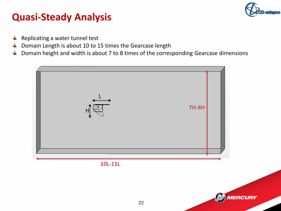
22
Replicating a water tunnel testDomain Length is about 10 to 15 times the Gearcase lengthDomain height and width is about 7 to 8 times of the corresponding Gearcase dimensions
L
H
10L-15L
7H-8H
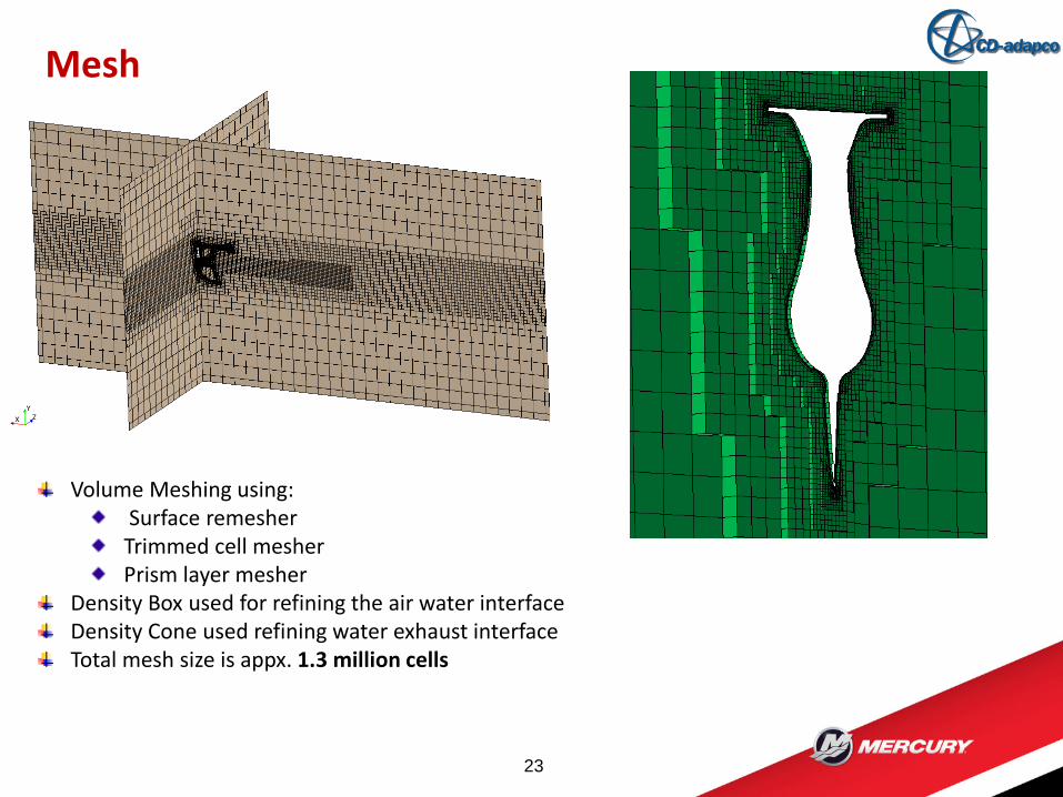
Mesh
23
Volume Meshing using:Surface remesherTrimmed cell mesherPrism layer mesher
Density Box used for refining the air water interfaceDensity Cone used refining water exhaust interfaceTotal mesh size is appx. 1.3 million cells
Segregated Flow
Implicit Unsteady
Realizable K-ε turbulence model
Eulerian Multiphase Mixture Model
– Air
– Water
– Exhaust
– Vapor
Volume of Fluid (VOF) Method
VOF Phase Interaction with Cavitation
– Primary Phase: Water
– Secondary Phase: Vapor
VOF Waves
Physics Model
24
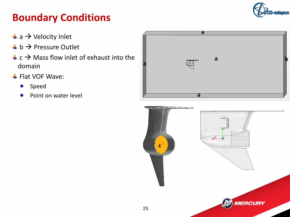
Boundary Conditions
25
a
aa
a
b
a Velocity Inlet
b Pressure Outlet
c Mass flow inlet of exhaust into the domain
Flat VOF Wave:
Speed
Point on water level
c
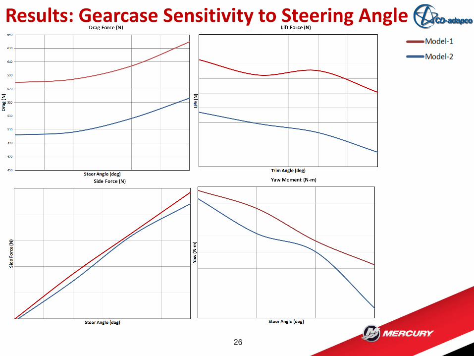
Results: Gearcase Sensitivity to Steering Angle
26
Pressure Coefficients at different steer angles show cavitation zones
It also highlights zones more prone to cavitation
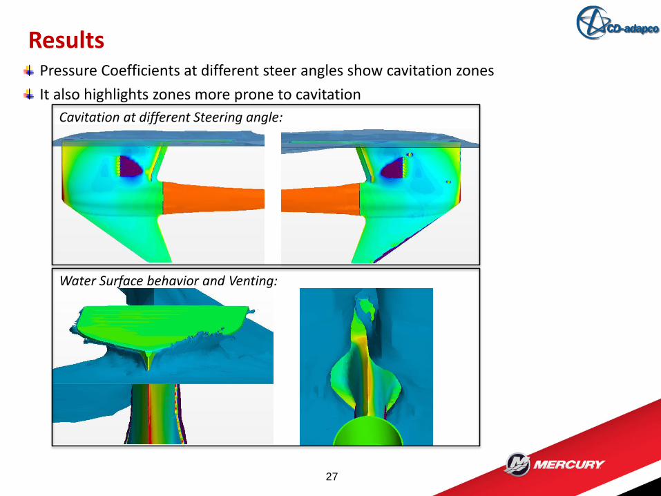
Results
27
Cavitation at different Steering angle:
Water Surface behavior and Venting:
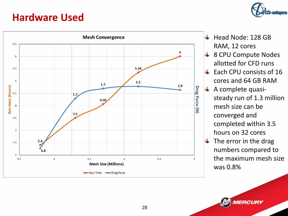
Hardware Used
28
Head Node: 128 GB RAM, 12 cores8 CPU Compute Nodes allotted for CFD runsEach CPU consists of 16 cores and 64 GB RAMA complete quasi-steady run of 1.3 million mesh size can be converged and completed within 3.5 hours on 32 coresThe error in the drag numbers compared to the maximum mesh size was 0.8%
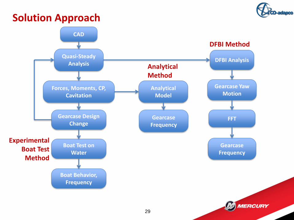
Solution Approach
29
CAD
Quasi-Steady Analysis
Forces, Moments, CP, Cavitation
Gearcase Design Change
Boat Test on Water
Boat Behavior, Frequency
Analytical Model
Gearcase Frequency
DFBI Analysis
Gearcase Yaw Motion
FFT
Gearcase Frequency
DFBI Method
Analytical Method
Experimental Boat Test
Method
Solution Approach
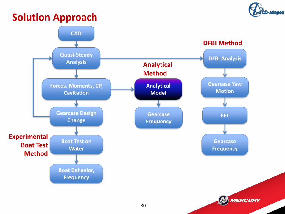
30
CAD
Quasi-Steady Analysis
Forces, Moments, CP, Cavitation
Gearcase Design Change
Boat Test on Water
Boat Behavior, Frequency
Analytical Model
Gearcase Frequency
DFBI Analysis
Gearcase Yaw Motion
FFT
Gearcase Frequency
DFBI Method
Analytical Method
Experimental Boat Test
Method
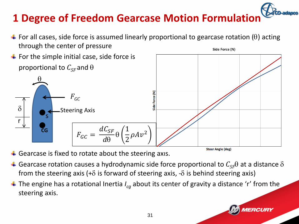
For all cases, side force is assumed linearly proportional to gearcase rotation (q) acting through the center of pressure
For the simple initial case, side force is
proportional to CSF and q
Gearcase is fixed to rotate about the steering axis.
Gearcase rotation causes a hydrodynamic side force proportional to CSFq at a distance dfrom the steering axis (+d is forward of steering axis, -d is behind steering axis)
The engine has a rotational Inertia Icg about its center of gravity a distance ‘r’ from the steering axis.
1 Degree of Freedom Gearcase Motion Formulation
31
FGC
q
Steering Axisds
CG
r
𝐹𝐺𝐶 =𝑑𝐶𝑆𝐹𝑑q
q1
2𝜌𝐴𝑣2

Solution Approach
32
CAD
Quasi-Steady Analysis
Forces, Moments, CP, Cavitation
Gearcase Design Change
Boat Test on Water
Boat Behavior, Frequency
Analytical Model
Gearcase Frequency
DFBI Analysis
Gearcase Yaw Motion
FFT
Gearcase Frequency
DFBI Method
Analytical Method
Experimental Boat Test
Method
Solution Approach
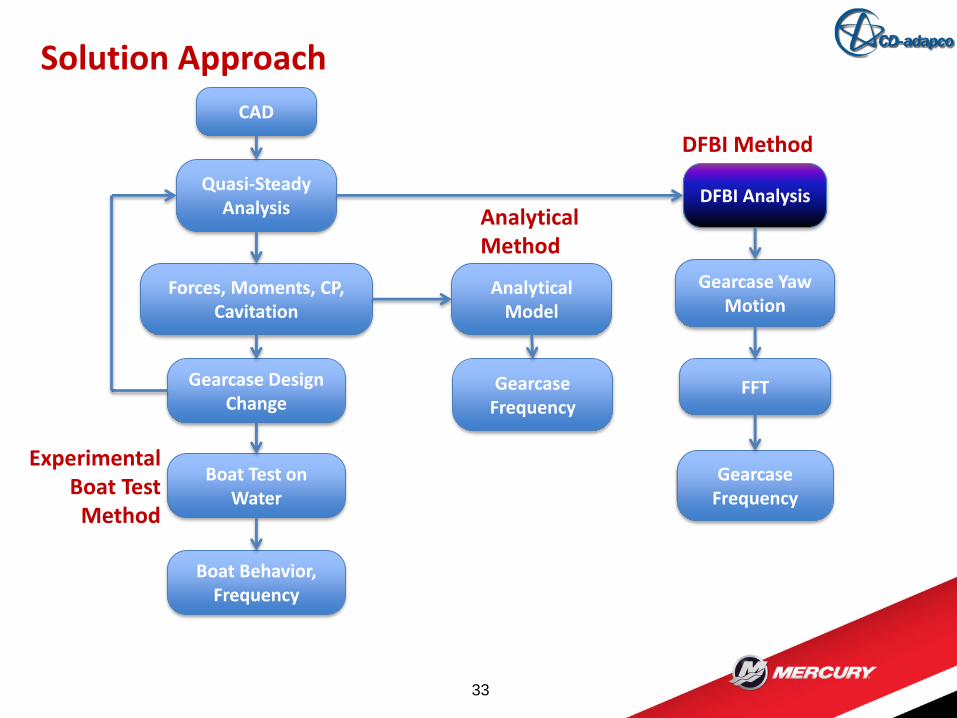
33
CAD
Quasi-Steady Analysis
Forces, Moments, CP, Cavitation
Gearcase Design Change
Boat Test on Water
Boat Behavior, Frequency
Analytical Model
Gearcase Frequency
DFBI Analysis
Gearcase Yaw Motion
FFT
Gearcase Frequency
DFBI Method
Analytical Method
Experimental Boat Test
Method
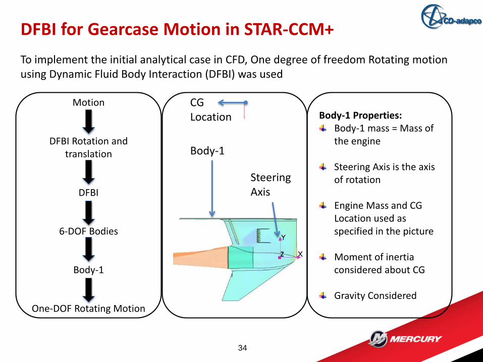
To implement the initial analytical case in CFD, One degree of freedom Rotating motion using Dynamic Fluid Body Interaction (DFBI) was used
DFBI for Gearcase Motion in STAR-CCM+
34
Motion
DFBI Rotation and translation
DFBI
6-DOF Bodies
Body-1
One-DOF Rotating Motion
CGLocation
Body-1
Steering Axis
Body-1 Properties:Body-1 mass = Mass of the engine
Steering Axis is the axis of rotation
Engine Mass and CG Location used as specified in the picture
Moment of inertia considered about CG
Gravity Considered
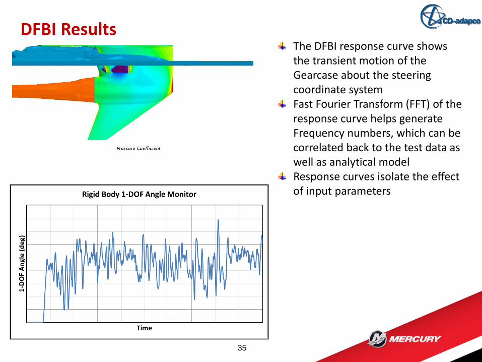
DFBI Results
35
The DFBI response curve shows the transient motion of the Gearcase about the steering coordinate systemFast Fourier Transform (FFT) of the response curve helps generate Frequency numbers, which can be correlated back to the test data as well as analytical modelResponse curves isolate the effect of input parameters
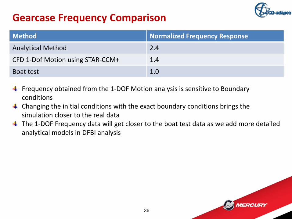
Method Normalized Frequency Response
Analytical Method 2.4
CFD 1-Dof Motion using STAR-CCM+ 1.4
Boat test 1.0
Gearcase Frequency Comparison
36
Frequency obtained from the 1-DOF Motion analysis is sensitive to Boundary conditionsChanging the initial conditions with the exact boundary conditions brings the simulation closer to the real dataThe 1-DOF Frequency data will get closer to the boat test data as we add more detailed analytical models in DFBI analysis
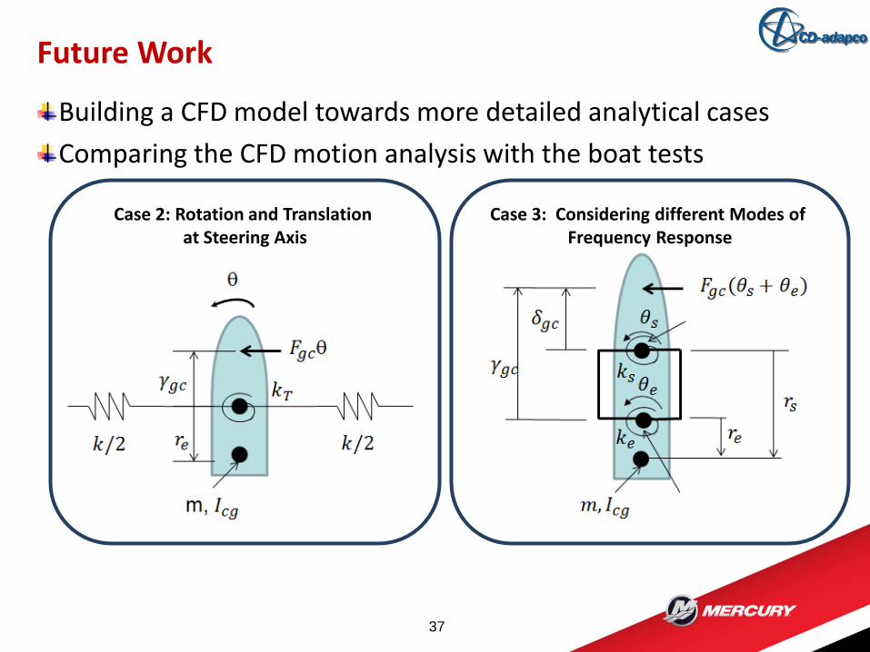
Building a CFD model towards more detailed analytical cases
Comparing the CFD motion analysis with the boat tests
Future Work
37
Case 2: Rotation and Translation at Steering Axis
Case 3: Considering different Modes of Frequency Response
Co-author: Paul Radavich
Mercury Marine Team
CD-adapco™ for all the support
Acknowledgements
38
39