Embed Size (px)
Citation preview
© 2
012
Mer
cury
Mar
ine
Axiu
s G
ener
atio
n 2
*8M005
2426*
90-8
M00
5242
6 1
210
NOTE: The following applies to CE marked products only.
Trademark and Copyright InformationThe description and specifications contained herein were in effect at the time this guide was approved for printing.Mercury Marine, whose policy is one of continuous improvement, reserves the right to discontinue models at any time,or to change specifications or designs, without notice and without incurring obligation.Mercury Marine, Fond du Lac, Wisconsin, USA. Printed in USA.© 2010, Mercury MarineMercury, Mercury Marine, MerCruiser, Mercury MerCruiser, Mercury Racing, Mercury Precision Parts, MercuryPropellers, Mariner, Quicksilver, #1 On The Water, Alpha, Bravo, Bravo Two, Bravo Three, Pro Max, OptiMax,Sport‑Jet, JetDrive, K‑Planes, MerCathode, RideGuide, SmartCraft, Zero Effort, VesselView, Zeus, Axius, TotalCommand, M with Waves logo, Mercury with Waves logo, and SmartCraft logo are all trademarks or registeredtrademarks of Brunswick Corporation. Mercury Product Protection logo is a registered service mark of BrunswickCorporation.
WelcomeYou have selected one of the finest marine power packages available. It incorporates numerous design features toassure operating ease and durability.With proper care and maintenance, you will thoroughly enjoy using this product for many boating seasons. This manualis a supplement to the owners manual provided with your engine, and provides additional information about the AxiusPropulsion system. To ensure maximum performance and carefree use, we ask that you thoroughly read this manual.This Owners and Operator Manual contains specific instructions for using and maintaining your product.Keep this manual with the product for ready reference whenever you are on the water.Thank you for purchasing one of our products. We sincerely hope your boating will be pleasant!
Warranty MessageThe product you have purchased comes with a limited warranty from Mercury Marine or Cummins MerCruiser Diesel;the terms of the warranty are set forth in the Warranty Sections of the Operation, Maintenance and Warranty Manualincluded with your power package. The warranty statement contains a description of what is covered, what is notcovered, the duration of coverage, how to best obtain warranty coverage, important disclaimers and limitations ofdamages and other related information. Please review this important information.
Read This Manual ThoroughlyIMPORTANT: If you do not understand any portion of this manual, contact your dealer for a demonstration of actualstarting and operating procedures.
NoticeThroughout this publication, and on your power package, dangers, warnings, cautions, and notices, accompanied by the
International Hazard Symbol ! , may be used to alert the installer/user to special instructions concerning a particularservice or operation that may be hazardous if performed incorrectly or carelessly. Observe them carefully.These Safety Alerts alone cannot eliminate the hazards that they signal. Strict compliance with these special instructionswhile performing the service, plus common sense operation, are major accident prevention measures.
! DANGERIndicates a hazardous situation which, if not avoided, will result in death or serious injury.
! WARNINGIndicates a hazardous situation which, if not avoided, could result in death or serious injury.
! CAUTIONIndicates a hazardous situation which, if not avoided, could result in minor or moderate injury.
NOTICEIndicates a situation which, if not avoided, could result in engine or major component failure.

IMPORTANT: Identifies information essential to the successful completion of the task.NOTE: Indicates information that helps in the understanding of a particular step or action.
! WARNINGThe operator (driver) is responsible for the correct and safe operation of the boat, the equipment aboard and the safety of alloccupants aboard. We strongly recommend that the operator read this Operation, Maintenance and Warranty Manual andthoroughly understand the operational instructions for the power package and all related accessories before the boat is used.
! WARNINGThe engine exhaust from this product contains chemicals known to the state of California to cause cancer, birth defects orother reproductive harm.
90-8M0052426 eng DECEMBER 2010 Page i
TABLE OF CONTENTS
Section 1 - Getting to Know the Axius System
Features and Controls............................................................... 2Instrumentation................................................................... 2
Propulsion Personality ................................................... 2VesselView (If Equipped)............................................... 2SC1000 and SC100 System Link Digital Gauges (IfEquipped)....................................................................... 2Analog Gauges (If Equipped)......................................... 3
Electronic Helm Steering.................................................... 3Electronic Helm Steering................................................ 3
Joystick—Basic Operation.................................................. 4Engine Guardian Strategy.................................................. 4
Axius Premier Features (If Equipped)........................................ 5Axius Premier Precision Pilot Trackpad Functions............. 5
Section 2 - On the Water
Getting Started........................................................................... 8Traditional Maneuvering with Steering and Thrust............. 8
To Maneuver the Boat in Forward or Reverse............... 8To Steer the Boat in Tight Turns at Low Speeds............8To Spin the Boat at Low Speeds.................................... 8
Maneuvering After Engine or Module Failure..................... 8Maneuvering with the Joystick............................................ 8Special Digital Throttle and Shift (DTS) Features............... 9
Dock............................................................................. 10Throttle Only................................................................. 111 (Single) Lever............................................................ 12Sync..............................................................................12Troll...............................................................................13Transfer (If equipped with dual helms)......................... 13
Axius Premier (If Equipped)..................................................... 13Chartplotter Requirements................................................ 13Axius Premier Trackpad Features.................................... 13
General Information...................................................... 13Standby........................................................................ 13Standby and Active Lights............................................ 14Power Icon....................................................................14Auto Heading................................................................ 15Heading Adjustment and Override............................... 18
Disengaging Auto Heading........................................... 18To Resume to a Heading .............................................18
Skyhook—Station Keeping (Optional).............................. 19Precision Pilot Modes....................................................... 20Track Waypoint................................................................. 21
Engaging Track Waypoint Mode.................................. 21Disengaging Track Waypoint Mode..............................22Auto Heading Button in Track Waypoint Mode ............22Acknowledging a Turn During a Waypoint Arrival........ 22Waypoint Sequence..................................................... 23
Cruise Control................................................................... 25Dual Helm (If Equipped)........................................................... 26
Dual‑Helm Station Transfer.............................................. 26DTS.............................................................................. 26Axius............................................................................. 26
Battery Information................................................................... 27Long Term Battery Storage & MaintenanceRecommendations............................................................ 27
Recommissioning......................................................... 27Contingent Operations............................................................. 28
Port Engine–Only Operation............................................. 28Axius Shift Override—Emergency Procedure................... 28
Transporting an Axius Boat...................................................... 29
Section 3 - Troubleshooting
Check VesselView First........................................................... 32Diagnosing DTS Problems....................................................... 32Engine Guardian System......................................................... 32Troubleshooting Charts............................................................ 32
Joystick............................................................................. 32
Electronic Remote Controls.............................................. 33Steering System............................................................... 34Trackpad Features............................................................ 34Auto Pilot.......................................................................... 34Skyhook............................................................................ 35
Section 4 - Customer Assistance Information
Owner Service Assistance....................................................... 38Local Repair Service.......................................................... 38Service Away From Home..................................................38Stolen Power Package....................................................... 38Attention Required After Submersion................................. 38Replacement Service Parts................................................ 38
Parts and Accessories Inquiries................................... 38
Resolving a Problem.......................................................... 38Contact Information for Mercury Marine Customer Service........................................................................................... 39
Ordering Literature................................................................... 39United States and Canada................................................. 39Outside the United States and Canada.............................. 40

Page ii 90-8M0052426 eng DECEMBER 2010
Section 5 - Predelivery (PDI) and Customer Delivery (CDI) Checklists
Predelivery Inspection (PDI)................................................... 42 Customer Delivery Inspection (CDI)....................................... 44
Section 1 - Getting to Know the Axius System
90-8M0052426 eng DECEMBER 2010 Page 1
Section 1 - Getting to Know the Axius SystemTable of ContentsFeatures and Controls............................................................ 2
Instrumentation................................................................ 2Propulsion Personality ............................................ 2VesselView (If Equipped) ........................................ 2SC1000 and SC100 System Link Digital Gauges (IfEquipped) ................................................................ 2Analog Gauges (If Equipped) .................................. 3
Electronic Helm Steering................................................. 3Electronic Helm Steering ......................................... 3
Joystick—Basic Operation............................................... 4Engine Guardian Strategy............................................... 4
Axius Premier Features (If Equipped).................................... 5Axius Premier Precision Pilot Trackpad Functions.......... 5
1
Section 1 - Getting to Know the Axius System
Page 2 90-8M0052426 eng DECEMBER 2010
Features and ControlsInstrumentationPropulsion Personality
The propulsion personality was developed by Mercury MerCruiser and your boat builder to ensure that vessel performanceregarding joystick, steering, and autopilot work optimally for your vessel in ideal conditions. As conditions vary, such as windand current, additional user input may be required to compensate.Changing engine performance, gear ratios, or propeller may affect the performance of the joystick as well as the top speed ofthe vessel. Changing any parameter from the original factory equipment and settings can have a negative affect onperformance, and changes should not be made without consulting the OEM and a MerCuiser product integration engineer first.The vessel personality is the property of the OEM, and any changes or upgrades to the personality must be approved anddistributed by the OEM. Mercury will assist with software personality changes only at the request of the boat manufacturer.
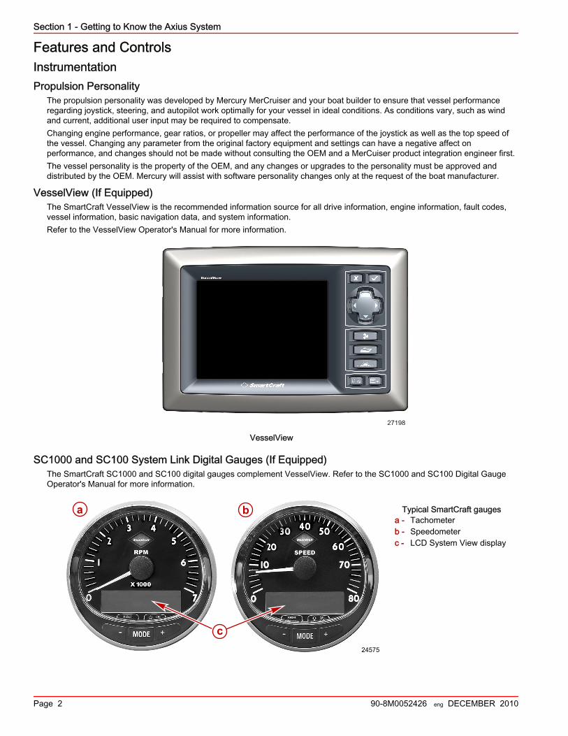
VesselView (If Equipped)The SmartCraft VesselView is the recommended information source for all drive information, engine information, fault codes,vessel information, basic navigation data, and system information.Refer to the VesselView Operator's Manual for more information.
27198
VesselView
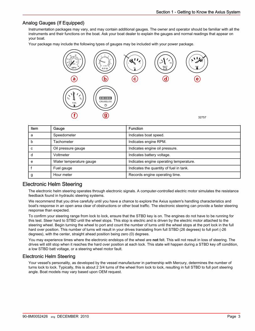
SC1000 and SC100 System Link Digital Gauges (If Equipped)The SmartCraft SC1000 and SC100 digital gauges complement VesselView. Refer to the SC1000 and SC100 Digital GaugeOperator's Manual for more information.
Typical SmartCraft gaugesa - Tachometerb - Speedometerc - LCD System View display
24575
a b
cc
Section 1 - Getting to Know the Axius System
90-8M0052426 eng DECEMBER 2010 Page 3
Analog Gauges (If Equipped)Instrumentation packages may vary, and may contain additional gauges. The owner and operator should be familiar with all theinstruments and their functions on the boat. Ask your boat dealer to explain the gauges and normal readings that appear onyour boat.Your package may include the following types of gauges may be included with your power package.
L H
OIL
C H
TEMP0
1
2
34
5
6
7
8R P M
X 1000
MPH
KPH
1020
30
40
50 60
70
80
3040506070
8090100
120
110
10 16
BATT
04 4
4
FUELCRUISELOG
0 0 0 0 0
a b c d e
f g 32757
Item Gauge Function
a Speedometer Indicates boat speed.
b Tachometer Indicates engine RPM.
c Oil pressure gauge Indicates engine oil pressure.
d Voltmeter Indicates battery voltage.
e Water temperature gauge Indicates engine operating temperature.
f Fuel gauge Indicates the quantity of fuel in tank.
g Hour meter Records engine operating time.
Electronic Helm SteeringThe electronic helm steering operates through electronic signals. A computer‑controlled electric motor simulates the resistancefeedback found in hydraulic steering systems.We recommend that you drive carefully until you have a chance to explore the Axius system's handling characteristics andboat's response in an open area clear of obstructions or other boat traffic. The electronic steering can provide a faster steeringresponse than expected.To confirm your steering range from lock to lock, ensure that the STBD key is on. The engines do not have to be running forthis test. Steer hard to STBD until the wheel stops. This stop is electric and is driven by the electric motor attached to thesteering wheel. Begin turning the wheel to port and count the number of turns until the wheel stops at the port lock in the fullhard over position. This number of turns will result in your drives translating from full STBD (26 degrees) to full port (‑26degrees), with the center, straight ahead position being zero (0) degrees.You may experience times where the electronic endstops of the wheel are not felt. This will not result in loss of steering. Thedrives will still stop when it reaches the hard over position at each lock. This state will happen during a STBD key off condition,a low STBD batt voltage, or a steering wheel motor fault.
Electronic Helm SteeringYour vessel's personality, as developed by the vessel manufacturer in partnership with Mercury, determines the number ofturns lock to lock. Typically, this is about 2 3/4 turns of the wheel from lock to lock, resulting in full STBD to full port steeringangle. Boat models may vary based upon OEM request.
Section 1 - Getting to Know the Axius System
Page 4 90-8M0052426 eng DECEMBER 2010
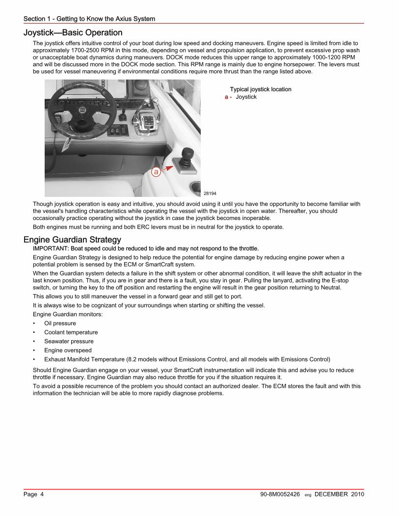
Joystick—Basic OperationThe joystick offers intuitive control of your boat during low speed and docking maneuvers. Engine speed is limited from idle toapproximately 1700‑2500 RPM in this mode, depending on vessel and propulsion application, to prevent excessive prop washor unacceptable boat dynamics during maneuvers. DOCK mode reduces this upper range to approximately 1000‑1200 RPMand will be discussed more in the DOCK mode section. This RPM range is mainly due to engine horsepower. The levers mustbe used for vessel maneuvering if environmental conditions require more thrust than the range listed above.
Typical joystick locationa - Joystick
Though joystick operation is easy and intuitive, you should avoid using it until you have the opportunity to become familiar withthe vessel's handling characteristics while operating the vessel with the joystick in open water. Thereafter, you shouldoccasionally practice operating without the joystick in case the joystick becomes inoperable.Both engines must be running and both ERC levers must be in neutral for the joystick to operate.
Engine Guardian StrategyIMPORTANT: Boat speed could be reduced to idle and may not respond to the throttle.Engine Guardian Strategy is designed to help reduce the potential for engine damage by reducing engine power when apotential problem is sensed by the ECM or SmartCraft system.When the Guardian system detects a failure in the shift system or other abnormal condition, it will leave the shift actuator in thelast known position. Thus, if you are in gear and there is a fault, you stay in gear. Pulling the lanyard, activating the E‑stopswitch, or turning the key to the off position and restarting the engine will result in the gear position returning to Neutral.This allows you to still maneuver the vessel in a forward gear and still get to port.It is always wise to be cognizant of your surroundings when starting or shifting the vessel.Engine Guardian monitors:• Oil pressure• Coolant temperature• Seawater pressure• Engine overspeed• Exhaust Manifold Temperature (8.2 models without Emissions Control, and all models with Emissions Control)
Should Engine Guardian engage on your vessel, your SmartCraft instrumentation will indicate this and advise you to reducethrottle if necessary. Engine Guardian may also reduce throttle for you if the situation requires it.To avoid a possible recurrence of the problem you should contact an authorized dealer. The ECM stores the fault and with thisinformation the technician will be able to more rapidly diagnose problems.
a
28194
Section 1 - Getting to Know the Axius System
90-8M0052426 eng DECEMBER 2010 Page 5
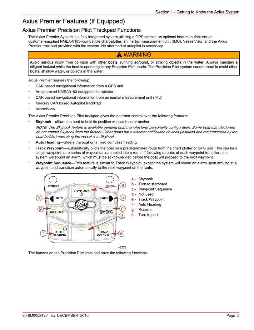
Axius Premier Features (If Equipped)Axius Premier Precision Pilot Trackpad Functions
The Axius Premier System is a fully integrated system utilizing a GPS sensor, an optional boat manufacturer orcustomer‑supplied NMEA‑0183–compatible chart‑plotter, an inertial measurement unit (IMU), VesselView, and the AxiusPremier trackpad provided with the system. No aftermarket autopilot is necessary.
! WARNINGAvoid serious injury from collision with other boats, running aground, or striking objects in the water. Always maintain adiligent lookout while the boat is operating in any Precision Pilot mode. The Precision Pilot system cannot react to avoid otherboats, shallow water, or objects in the water.
Axius Premier requires the following:• CAN based navigational information from a GPS unit• An approved NMEA0183 equipped chartplotter• CAN based navigational information from an inertial measurement unit (IMU)• Mercury CAN based Autopilot trackPad• VesselView
The Axius Premier Precision Pilot trackpad gives the operator control over the following features:• Skyhook—allows the boat to hold its position without lines or anchor
NOTE: The Skyhook feature is available pending boat manufacturer personality configuration. Some boat manufacturersdo not enable Skyhook from the factory. Other boats have external notification devices (installed and manufactured by theboat builder) indicating the vessel is in Skyhook.
• Auto Heading—Steers the boat on a fixed compass heading• Track Waypoint—Automatically pilots the boat on a predetermined route from the chart plotter or GPS unit. This can be a
single waypoint, or a series of waypoints assembled into a route. If following a route, at each waypoint transition, thesystem will sound an alarm, which must be acknowledged before the boat will proceed to the next waypoint.
• Waypoint Sequence—This feature is similar to Track Waypoint, except the system will sound an alarm upon arriving at awaypoint and transition automatically to the next waypoint on the route.
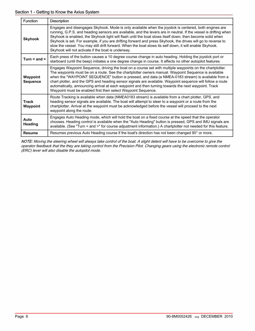
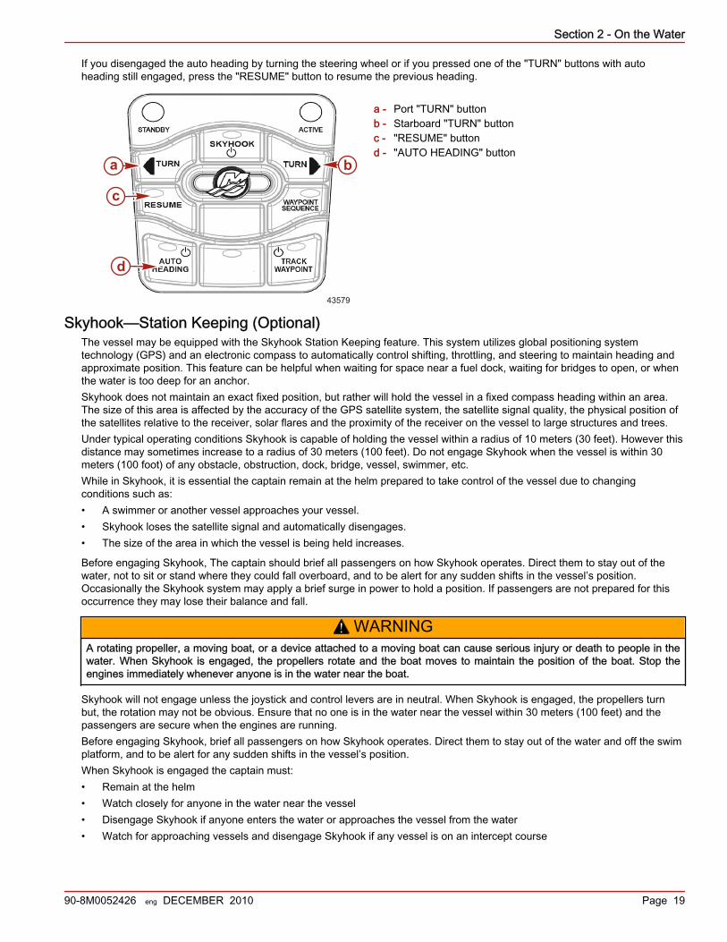
a - Skyhookb - Turn to starboardc - Waypoint Sequenced - Not usede - Track Waypointf - Auto Headingg - Resumeh - Turn to port
The buttons on the Precision Pilot trackpad have the following functions:43573
a
b
cd
ef
g
h
Section 1 - Getting to Know the Axius System
Page 6 90-8M0052426 eng DECEMBER 2010
Function Description
Skyhook
Engages and disengages Skyhook. Mode is only available when the joystick is centered, both engines arerunning, G.P.S. and heading sensors are available, and the levers are in neutral. If the vessel is drifting whenSkyhook is enabled, the Skyhook light will flash until the boat slows itself down, then become solid whenSkyhook is set. For example, if you are drifting forward and press Skyhook, the drives will go to reverse toslow the vessel. You may still drift forward. When the boat slows its self down, it will enable Skyhook.Skyhook will not activate if the boat is underway.
Turn < and > Each press of the button causes a 10 degree course change in auto heading. Holding the joystick port orstarboard (until the beep) initiates a one degree change in course. It affects no other autopilot features.
WaypointSequence
Engages Waypoint Sequence, driving the boat on a course set with multiple waypoints on the chartplotter.The waypoints must be on a route. See the chartplotter owners manual. Waypoint Sequence is availablewhen the "WAYPOINT SEQUENCE" button is pressed, and data (a NMEA‑0183 stream) is available from achart plotter, and the GPS and heading sensor signals are available. Waypoint sequence will follow a routeautomatically, announcing arrival at each waypoint and then turning towards the next waypoint. TrackWaypoint must be enabled first then select Waypoint Sequence.
TrackWaypoint
Route Tracking is available when data (NMEA0183 stream) is available from a chart plotter, GPS, andheading sensor signals are available. The boat will attempt to steer to a waypoint or a route from thechartplotter. Arrival at the waypoint must be acknowledged before the vessel will proceed to the nextwaypoint along the route.
AutoHeading
Engages Auto Heading mode, which will hold the boat on a fixed course at the speed that the operatorchooses. Heading control is available when the "Auto Heading" button is pressed, GPS and IMU signals areavailable. (See "Turn < and >" for course adjustment information.) A chartplotter not needed for this feature.
Resume Resumes previous Auto Heading course if the boat's direction has not been changed 90° or more.
NOTE: Moving the steering wheel will always take control of the boat. A slight detent will have to be overcome to give theoperator feedback that the they are taking control from the Precision Pilot. Changing gears using the electronic remote control(ERC) lever will also disable the autopilot mode.
Section 2 - On the Water
90-8M0052426 eng DECEMBER 2010 Page 7
Section 2 - On the WaterTable of ContentsGetting Started....................................................................... 8
Traditional Maneuvering with Steering and Thrust.......... 8To Maneuver the Boat in Forward or Reverse ........ 8To Steer the Boat in Tight Turns at LowSpeeds .................................................................... 8To Spin the Boat at Low Speeds ............................. 8
Maneuvering After Engine or Module Failure.................. 8Maneuvering with the Joystick......................................... 8Special Digital Throttle and Shift (DTS) Features............ 9
Dock ...................................................................... 10Throttle Only .......................................................... 111 (Single) Lever ..................................................... 12Sync ...................................................................... 12Troll ....................................................................... 13Transfer (If equipped with dual helms) .................. 13
Axius Premier (If Equipped).................................................. 13Chartplotter Requirements.............................................13Axius Premier Trackpad Features................................. 13
General Information ............................................... 13Standby ................................................................. 13Standby and Active Lights ..................................... 14Power Icon ............................................................ 14Auto Heading ......................................................... 15Heading Adjustment and Override ........................ 18
Disengaging Auto Heading .................................... 18To Resume to a Heading ..................................... 18
Skyhook—Station Keeping (Optional)........................... 19Precision Pilot Modes.................................................... 20Track Waypoint.............................................................. 21
Engaging Track Waypoint Mode ........................... 21Disengaging Track Waypoint Mode ...................... 22Auto Heading Button in Track Waypoint Mode .... 22Acknowledging a Turn During a WaypointArrival .................................................................... 22Waypoint Sequence .............................................. 23
Cruise Control................................................................ 25Dual Helm (If Equipped)....................................................... 26
Dual‑Helm Station Transfer........................................... 26DTS ....................................................................... 26Axius ...................................................................... 26
Battery Information............................................................... 27Long Term Battery Storage & MaintenanceRecommendations......................................................... 27
Recommissioning .................................................. 27Contingent Operations.......................................................... 28
Port Engine–Only Operation.......................................... 28Axius Shift Override—Emergency Procedure................28
Transporting an Axius Boat.................................................. 29
2
Section 2 - On the Water
Page 8 90-8M0052426 eng DECEMBER 2010
Getting StartedTraditional Maneuvering with Steering and Thrust
You can maneuver your Axius‑equipped vessel much like a traditional sterndrive boat. However, the Axius drive systemexpands the maneuvering capability of your vessel at both slow and planing speeds. At slow speeds, the drive system iscapable of directing the thrust through independently articulating drives to produce more responsive turning of the vessel. TheAxius drive system features counter‑rotating propellers that do not produce any propsteer when accelerating or slowing down.
To Maneuver the Boat in Forward or ReversePlace one or both engines in forward or reverse gear and steer with the steering wheel as you would any comparable boat.
To Steer the Boat in Tight Turns at Low Speeds• To turn the boat in tight turns at low speeds, turn the wheel in the direction of the turn.• To increase the turn rate of the boat after the wheel is completely turned, you may increase the power to the inside drive.
To Spin the Boat at Low Speeds• Turn the drives to straight forward.• To spin to the right, place the starboard engine in reverse and the port engine in forward.• To spin to the left, place the port engine in reverse and the starboard engine in forward.• To increase the rate of turn, simultaneously adjust each ERC lever for more throttle. More reverse throttle will be needed to
compensate for the forward drive.
Maneuvering After Engine or Module FailureIf an engine, helm, or steering module stops functioning during use, the remaining drive is electronically limited while turninginboard. This limit is to remove the possibility of the drives making contact with each other, since the active drive is unable todetermine the position of the disabled drive. The boat is still operational, but maneuverability is decreased when turning towardthe side that is not working. Refer to the inboard drive angle limit in the table below. The drive is still capable of turning throughits full range when turning away from the disabled drive. Use extra caution when one of the drives is disabled.
Drive limits of engine with module failure
Engines, with and without Emissions Control Maximum Inboard Drive Angle Limit
5.0L, 350 MAG, 377 MAG models 3.0 Degrees
8.2L models 11.5 Degrees
The limit may be greater than specified in the table depending on the propulsion personality and distance between drives.
Maneuvering with the Joystick
! WARNINGA spinning propeller, a moving boat, or any solid device attached to the boat can cause serious injury or death to swimmers.Stop the engine immediately whenever anyone in the water is near your boat.
The joystick provides a single lever interface to maneuver the vessel. Operating the vessel with the joystick is well suited forclose quarter and docking operations in most situations. The computer control system automatically calculates the steeringangle of each drive, the throttle level, and the proper gear to push or rotate the boat in a direction corresponding to a joystickmovement or twist. For example, if you move the joystick sideways, the computer control system applies a thrust to the boat inthe sideways direction. Rotating the joystick prompts the computer to create forces that rotate the boat around its center. Youcan move and rotate the joystick at the same time, allowing intricate movements in tight quarters.The joystick is proportional, which means that the greater distance from the center that the joystick is moved, the more thrustthat is applied to the boat in that direction, to move the boat.For joystick movement of the boat:1. Both engines must be running for the joystick to operate.2. For best control, trim both drives to the full down position. VesselView will display a reminder when the joystick is initiated.3. Move both electronic remote control (ERC) levers to the neutral position.4. Move the joystick in the direction that you want the boat to move, or twist the joystick in the direction that you want the boat
to rotate. The joystick can be moved and rotated at the same time.
Section 2 - On the Water
90-8M0052426 eng DECEMBER 2010 Page 9
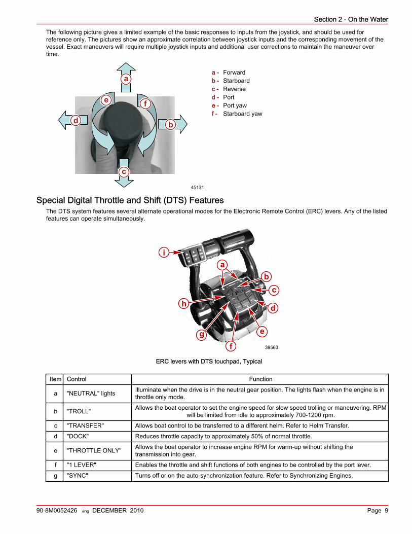
The following picture gives a limited example of the basic responses to inputs from the joystick, and should be used forreference only. The pictures show an approximate correlation between joystick inputs and the corresponding movement of thevessel. Exact maneuvers will require multiple joystick inputs and additional user corrections to maintain the maneuver overtime.
a - Forwardb - Starboardc - Reversed - Porte - Port yawf - Starboard yaw
Special Digital Throttle and Shift (DTS) FeaturesThe DTS system features several alternate operational modes for the Electronic Remote Control (ERC) levers. Any of the listedfeatures can operate simultaneously.
ia
bc
d
e
fg
h
a
39563
ERC levers with DTS touchpad, Typical
Item Control Function
a "NEUTRAL" lights Illuminate when the drive is in the neutral gear position. The lights flash when the engine is inthrottle only mode.
b "TROLL" Allows the boat operator to set the engine speed for slow speed trolling or maneuvering. RPMwill be limited from idle to approximately 700‑1200 rpm.
c "TRANSFER" Allows boat control to be transferred to a different helm. Refer to Helm Transfer.
d "DOCK" Reduces throttle capacity to approximately 50% of normal throttle.
e "THROTTLE ONLY" Allows the boat operator to increase engine RPM for warm‑up without shifting thetransmission into gear.
f "1 LEVER" Enables the throttle and shift functions of both engines to be controlled by the port lever.
g "SYNC" Turns off or on the auto‑synchronization feature. Refer to Synchronizing Engines.
45131
a
b
e f
d
c
Section 2 - On the Water
Page 10 90-8M0052426 eng DECEMBER 2010
Item Control Function
h "+" (increase) and "–"(decrease) Increases and decreases settings for TROLL.
i Trim controls Raises and lowers the drives for best efficiency, or for conditions like shallow water, trailering,etc..
NOTE: Not all functions may be active.
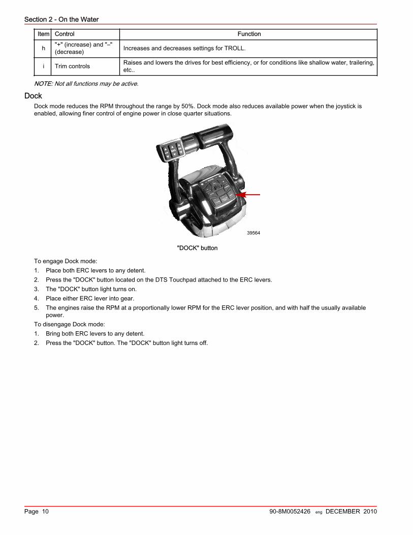
DockDock mode reduces the RPM throughout the range by 50%. Dock mode also reduces available power when the joystick isenabled, allowing finer control of engine power in close quarter situations.
39564
"DOCK" button
To engage Dock mode:1. Place both ERC levers to any detent.2. Press the "DOCK" button located on the DTS Touchpad attached to the ERC levers.3. The "DOCK" button light turns on.4. Place either ERC lever into gear.5. The engines raise the RPM at a proportionally lower RPM for the ERC lever position, and with half the usually available
power.To disengage Dock mode:1. Bring both ERC levers to any detent.2. Press the "DOCK" button. The "DOCK" button light turns off.
Section 2 - On the Water
90-8M0052426 eng DECEMBER 2010 Page 11
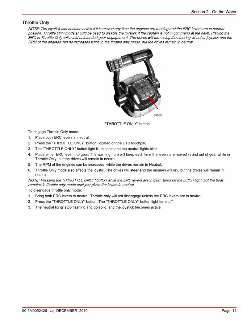
Throttle OnlyNOTE: The joystick can become active if it is moved any time the engines are running and the ERC levers are in neutralposition. Throttle Only mode should be used to disable the joystick if the captain is not in command at the helm. Placing theERC in Throttle Only will avoid unintended gear engagement. The drives will turn using the steering wheel or joystick and theRPM of the engines can be increased while in the throttle only mode, but the drives remain in neutral.
39565
"THROTTLE ONLY" button
To engage Throttle Only mode:1. Place both ERC levers in neutral.2. Press the "THROTTLE ONLY" button, located on the DTS touchpad.3. The "THROTTLE ONLY" button light illuminates and the neutral lights blink.4. Place either ERC lever into gear. The warning horn will beep each time the levers are moved in and out of gear while in
Throttle Only, but the drives will remain in neutral.5. The RPM of the engines can be increased, while the drives remain in Neutral.6. Throttle Only mode also affects the joystic. The drives will steer and the engines will rev, but the drives will remail in
neutral.NOTE: Pressing the "THROTTLE ONLY" button while the ERC levers are in gear, turns off the button light, but the boatremains in throttle only mode until you place the levers in neutral.To disengage throttle only mode:1. Bring both ERC levers to neutral. Throttle only will not disengage unless the ERC levers are in neutral.2. Press the "THROTTLE ONLY" button. The "THROTTLE ONLY" button light turns off.3. The neutral lights stop flashing and go solid, and the joystick becomes active.

Section 2 - On the Water
Page 12 90-8M0052426 eng DECEMBER 2010
1 (Single) LeverThe Axius system features the ability to command both engines with a single lever. This feature simplifies engine managementduring rough sea conditions by allowing you to grasp a single lever to command both engines simultaneously. It has no affecton Joystick function. It is not the same as the system feature called Sync.
39566
"1 LEVER" button
To engage 1 (single) lever mode:1. Place both ERC levers in neutral.2. Press the "1 LEVER" button located on the DTS Touchpad attached to the ERC levers.3. The "1 LEVER" button lights.4. Place the starboard ERC lever into gear.5. The engine RPM raises and lowers simultaneously while the drives remain in the same gear.To disengage 1 (single) lever mode:1. Place both ERC levers in neutral.2. Press the "1 LEVER" button. The "1 LEVER" button light turns off.
SyncThe Axius system features Sync, an automatic engine synchronization feature, which enables automatically at key‑up. Syncmonitors the position of both ERC levers. If both levers are within 10% of one another, the port engine synchronizes to thestarboard engine's RPM. The SmartCraft system will automatically disengage Sync at the last 95% of throttle position range toallow each engine the ability to reach maximum available RPM. Sync cannot engage until its minimum RPM is met.The indicator light on the "SYNC" button is on when both engines are on. The light is yellow when the engines are not beingsynced, at idle and 95% of throttle. The light turns red when the sync feature is working.
39567
"SYNC" button
Section 2 - On the Water
90-8M0052426 eng DECEMBER 2010 Page 13
The RPM display of VesselView also shows an orange icon under the RPM numbers if the engines exceed a 10% difference inRPM of each other, and the icon turns red when they synchronize.To disengage Sync mode:1. Place the ERC levers in any detent.2. Press the "SYNC" button.To re‑engage Sync mode, press the "SYNC" button.
TrollNOTE: The joystick is not active when Troll is active since Troll requires the ERC levers to be in detent gear to be active.Pressing the "TROLL" button activates troll control. The troll control feature allows the boat operator to set the engine speed forslow speed cruising or maneuvering.To engage Troll mode:1. Move the control handles into forward detent and press the "TROLL" button.2. Use the ‑ or + buttons to decrease or increase speed, up to a maximum of 1000 RPM.3. If Troll control is set at a desired speed and then shut off, the system remembers the set speed and will return to that
speed when reengaged.To disengage Troll mode, either:• Press the "TROLL" button• Move the throttle to a different speed.• Or shift the engine into neutral.
Transfer (If equipped with dual helms)The "TRANSFER" button allows the boat operator to transfer control of the boat from the active helm to the inactive helm onboats equipped with dual helms. Refer to Dual Helm Station Transfer.
Axius Premier (If Equipped)Chartplotter Requirements
Many of the features of Axius Premier use information from the chartplotter to function. However, not every chartplotter has thequality of information needed to allow these features to work properly. The chartplotter on your boat has been selected from anapproved list created and maintained by Mercury MerCruiser. These chartplotters use specific software to meet the stringentdemands to function with the Axius Premier system.Poor quality or inaccurate information generated by unapproved chartplotters or software can cause the features to behaveerratically, unexpectedly, or not function at all. Updating software to an unapproved version can also cause the system to notfunction correctly. See your dealer or call Mercury Customer Service for approved plotters, plotter settings, and compatiblesoftware in the event your chartplotter needs service.
Axius Premier Trackpad FeaturesGeneral Information
The following list provides some general information about the Axius Premier trackpad.• Axius Premier functions are controlled through the Axius trackpad only, and are displayed on VesselView.• All other Axius Premier trackpad screens appear on VesselView.• Pressing any button on VesselView dismisses the Axius Premier CAN trackpad screen from the VesselView screen, unless
the screen was chosen from the VesselView environment menu.
The following information shows the location and explains the function of the Axius trackpad lights and buttons.
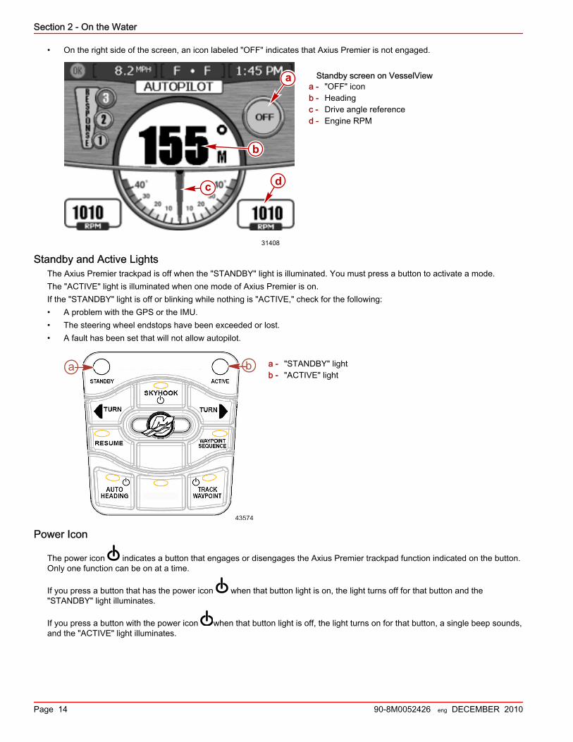
StandbyWhen Axius Premier is in Standby mode, the following information is shown on the VesselView:• In Standby mode, the display shows a digital compass value and the angle of the drives.• The compass value is the actual current heading from the Axius Inertial Measurement Unit (IMU).
Section 2 - On the Water
Page 14 90-8M0052426 eng DECEMBER 2010
• On the right side of the screen, an icon labeled "OFF" indicates that Axius Premier is not engaged.
Standby screen on VesselViewa - "OFF" iconb - Headingc - Drive angle referenced - Engine RPM
Standby and Active LightsThe Axius Premier trackpad is off when the "STANDBY" light is illuminated. You must press a button to activate a mode.The "ACTIVE" light is illuminated when one mode of Axius Premier is on.If the "STANDBY" light is off or blinking while nothing is "ACTIVE," check for the following:• A problem with the GPS or the IMU.• The steering wheel endstops have been exceeded or lost.• A fault has been set that will not allow autopilot.
a - "STANDBY" lightb - "ACTIVE" light
Power Icon
The power icon indicates a button that engages or disengages the Axius Premier trackpad function indicated on the button.Only one function can be on at a time.
If you press a button that has the power icon when that button light is on, the light turns off for that button and the"STANDBY" light illuminates.
If you press a button with the power icon when that button light is off, the light turns on for that button, a single beep sounds,and the "ACTIVE" light illuminates.
31408
b
c
a
d
43574
a b
Section 2 - On the Water
90-8M0052426 eng DECEMBER 2010 Page 15
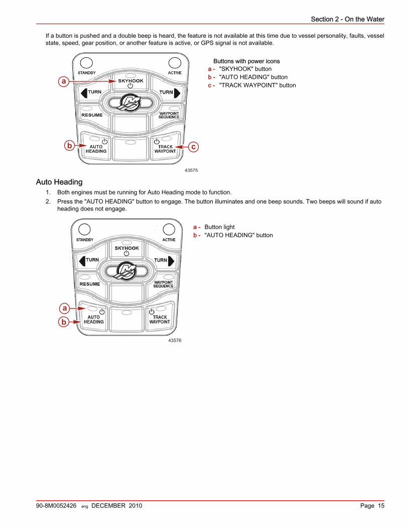
If a button is pushed and a double beep is heard, the feature is not available at this time due to vessel personality, faults, vesselstate, speed, gear position, or another feature is active, or GPS signal is not available.
Buttons with power iconsa - "SKYHOOK" buttonb - "AUTO HEADING" buttonc - "TRACK WAYPOINT" button
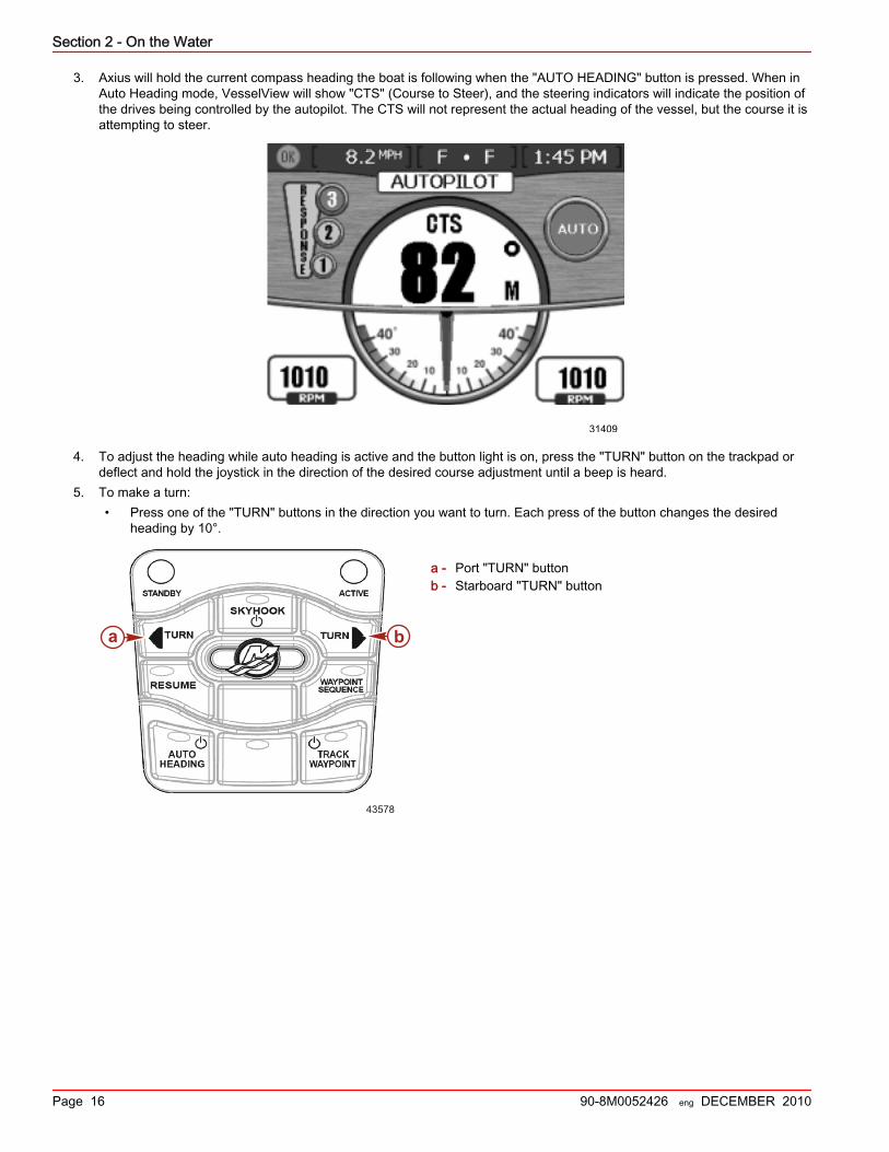
Auto Heading1. Both engines must be running for Auto Heading mode to function.2. Press the "AUTO HEADING" button to engage. The button illuminates and one beep sounds. Two beeps will sound if auto
heading does not engage.
a - Button lightb - "AUTO HEADING" button
43575
cb
a
43576
b
a
Section 2 - On the Water
Page 16 90-8M0052426 eng DECEMBER 2010
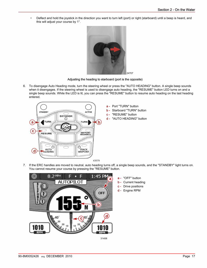
3. Axius will hold the current compass heading the boat is following when the "AUTO HEADING" button is pressed. When inAuto Heading mode, VesselView will show "CTS" (Course to Steer), and the steering indicators will indicate the position ofthe drives being controlled by the autopilot. The CTS will not represent the actual heading of the vessel, but the course it isattempting to steer.
31409
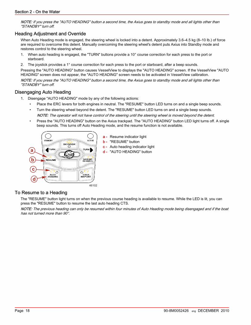
4. To adjust the heading while auto heading is active and the button light is on, press the "TURN" button on the trackpad ordeflect and hold the joystick in the direction of the desired course adjustment until a beep is heard.
5. To make a turn:• Press one of the "TURN" buttons in the direction you want to turn. Each press of the button changes the desired
heading by 10°.
a - Port "TURN" buttonb - Starboard "TURN" button
43578
ba
Section 2 - On the Water
90-8M0052426 eng DECEMBER 2010 Page 17
• Deflect and hold the joystick in the direction you want to turn left (port) or right (starboard) until a beep is heard, andthis will adjust your course by 1°.
24707
Adjusting the heading to starboard (port is the opposite)
6. To disengage Auto Heading mode, turn the steering wheel or press the "AUTO HEADING" button. A single beep soundswhen it disengages. If the steering wheel is used to disengage auto heading, the "RESUME" button LED turns on and asingle beep sounds. While the LED is lit, you can press the "RESUME" button to resume auto heading on the last headingentered.
a - Port "TURN" buttonb - Starboard "TURN" buttonc - "RESUME" buttond - "AUTO HEADING" button
7. If the ERC handles are moved to neutral, auto heading turns off, a single beep sounds, and the "STANDBY" light turns on.You cannot resume your course by pressing the "RESUME" button.
a - "OFF" buttonb - Current headingc - Drive positionsd - Engine RPM
43579
ba
c
d
31408
b
c
a
d
Section 2 - On the Water
Page 18 90-8M0052426 eng DECEMBER 2010
NOTE: If you press the "AUTO HEADING" button a second time, the Axius goes to standby mode and all lights other than"STANDBY" turn off.
Heading Adjustment and OverrideWhen Auto Heading mode is engaged, the steering wheel is locked into a detent. Approximately 3.6–4.5 kg (8–10 lb.) of forceare required to overcome this detent. Manually overcoming the steering wheel's detent puts Axius into Standby mode andrestores control to the steering wheel.1. When auto heading is engaged, the "TURN" buttons provide a 10° course correction for each press to the port or
starboard.2. The joystick provides a 1° course correction for each press to the port or starboard, after a beep sounds.Pressing the "AUTO HEADING" button causes VesselView to displays the "AUTO HEADING" screen. If the VesselView "AUTOHEADING" screen does not appear, the "AUTO HEADING" screen needs to be activated in VesselView calibration.NOTE: If you press the "AUTO HEADING" button a second time, the Axius goes to standby mode and all lights other than"STANDBY" turn off.
Disengaging Auto Heading1. Disengage "AUTO HEADING" mode by any of the following actions:
• Place the ERC levers for both engines in neutral. The "RESUME" button LED turns on and a single beep sounds.• Turn the steering wheel beyond the detent. The "RESUME" button LED turns on and a single beep sounds.
NOTE: The operator will not have control of the steering until the steering wheel is moved beyond the detent.• Press the "AUTO HEADING" button on the Axius trackpad. The "AUTO HEADING" button LED light turns off. A single
beep sounds. This turns off Auto Heading mode, and the resume function is not available.
a - Resume indicator lightb - "RESUME" buttonc - Auto heading indicator lightd - "AUTO HEADING" button
To Resume to a HeadingThe "RESUME" button light turns on when the previous course heading is available to resume. While the LED is lit, you canpress the "RESUME" button to resume the last auto heading CTS.NOTE: The previous heading can only be resumed within four minutes of Auto Heading mode being disengaged and if the boathas not turned more than 90°.
b
c
46102
a
d
Section 2 - On the Water
90-8M0052426 eng DECEMBER 2010 Page 19
If you disengaged the auto heading by turning the steering wheel or if you pressed one of the "TURN" buttons with autoheading still engaged, press the "RESUME" button to resume the previous heading.
a - Port "TURN" buttonb - Starboard "TURN" buttonc - "RESUME" buttond - "AUTO HEADING" button
Skyhook—Station Keeping (Optional)The vessel may be equipped with the Skyhook Station Keeping feature. This system utilizes global positioning systemtechnology (GPS) and an electronic compass to automatically control shifting, throttling, and steering to maintain heading andapproximate position. This feature can be helpful when waiting for space near a fuel dock, waiting for bridges to open, or whenthe water is too deep for an anchor.Skyhook does not maintain an exact fixed position, but rather will hold the vessel in a fixed compass heading within an area.The size of this area is affected by the accuracy of the GPS satellite system, the satellite signal quality, the physical position ofthe satellites relative to the receiver, solar flares and the proximity of the receiver on the vessel to large structures and trees.Under typical operating conditions Skyhook is capable of holding the vessel within a radius of 10 meters (30 feet). However thisdistance may sometimes increase to a radius of 30 meters (100 feet). Do not engage Skyhook when the vessel is within 30meters (100 foot) of any obstacle, obstruction, dock, bridge, vessel, swimmer, etc.While in Skyhook, it is essential the captain remain at the helm prepared to take control of the vessel due to changingconditions such as:• A swimmer or another vessel approaches your vessel.• Skyhook loses the satellite signal and automatically disengages.• The size of the area in which the vessel is being held increases.
Before engaging Skyhook, The captain should brief all passengers on how Skyhook operates. Direct them to stay out of thewater, not to sit or stand where they could fall overboard, and to be alert for any sudden shifts in the vessel’s position.Occasionally the Skyhook system may apply a brief surge in power to hold a position. If passengers are not prepared for thisoccurrence they may lose their balance and fall.
! WARNINGA rotating propeller, a moving boat, or a device attached to a moving boat can cause serious injury or death to people in thewater. When Skyhook is engaged, the propellers rotate and the boat moves to maintain the position of the boat. Stop theengines immediately whenever anyone is in the water near the boat.
Skyhook will not engage unless the joystick and control levers are in neutral. When Skyhook is engaged, the propellers turnbut, the rotation may not be obvious. Ensure that no one is in the water near the vessel within 30 meters (100 feet) and thepassengers are secure when the engines are running.Before engaging Skyhook, brief all passengers on how Skyhook operates. Direct them to stay out of the water and off the swimplatform, and to be alert for any sudden shifts in the vessel’s position.When Skyhook is engaged the captain must:• Remain at the helm• Watch closely for anyone in the water near the vessel• Disengage Skyhook if anyone enters the water or approaches the vessel from the water• Watch for approaching vessels and disengage Skyhook if any vessel is on an intercept course
43579
ba
c
d
Section 2 - On the Water
Page 20 90-8M0052426 eng DECEMBER 2010
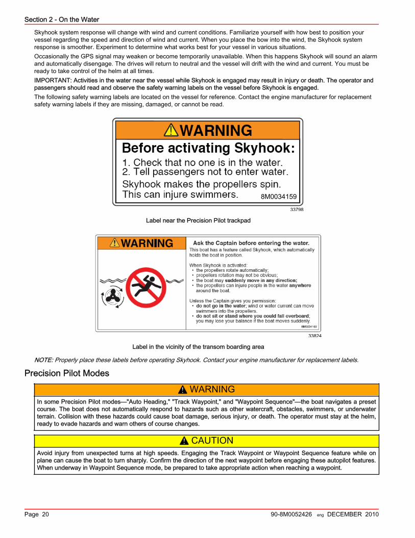
Skyhook system response will change with wind and current conditions. Familiarize yourself with how best to position yourvessel regarding the speed and direction of wind and current. When you place the bow into the wind, the Skyhook systemresponse is smoother. Experiment to determine what works best for your vessel in various situations.Occasionally the GPS signal may weaken or become temporarily unavailable. When this happens Skyhook will sound an alarmand automatically disengage. The drives will return to neutral and the vessel will drift with the wind and current. You must beready to take control of the helm at all times.IMPORTANT: Activities in the water near the vessel while Skyhook is engaged may result in injury or death. The operator andpassengers should read and observe the safety warning labels on the vessel before Skyhook is engaged.The following safety warning labels are located on the vessel for reference. Contact the engine manufacturer for replacementsafety warning labels if they are missing, damaged, or cannot be read.
33798
8M0034159
Label near the Precision Pilot trackpad
33824
Label in the vicinity of the transom boarding area
NOTE: Properly place these labels before operating Skyhook. Contact your engine manufacturer for replacement labels.
Precision Pilot Modes
! WARNINGIn some Precision Pilot modes—"Auto Heading," "Track Waypoint," and "Waypoint Sequence"—the boat navigates a presetcourse. The boat does not automatically respond to hazards such as other watercraft, obstacles, swimmers, or underwaterterrain. Collision with these hazards could cause boat damage, serious injury, or death. The operator must stay at the helm,ready to evade hazards and warn others of course changes.
! CAUTIONAvoid injury from unexpected turns at high speeds. Engaging the Track Waypoint or Waypoint Sequence feature while onplane can cause the boat to turn sharply. Confirm the direction of the next waypoint before engaging these autopilot features.When underway in Waypoint Sequence mode, be prepared to take appropriate action when reaching a waypoint.
Section 2 - On the Water
90-8M0052426 eng DECEMBER 2010 Page 21
Axius Premier contains several modes that can steer your vessel to a specific compass heading, or to destinations generatedfrom a chartplotter and GPS unit. If using a device to generate course information, you must be very familiar with the operationof that chartplotter and GPS unit before attempting to use Precision Pilot to steer your vessel. Precision Pilot does not controlspeed, only direction, and it can not sense hazards to navigation. These automatic modes do not relieve the operator of theresponsibility to stay at the helm and keep a vigilant lookout for other vessels, persons in the water, or hazards to navigation.If using Precision Pilot, a chartplotter, and a GPS unit to navigate along a series of waypoints (a route), be aware that the boatwill not travel to the precise location of the waypoint before initiating a turn to the next waypoint. Your chart plotter establishes azone around the point called an arrival circle, and the Precision Pilot system will announce arrival at the waypoint when theboat enters that zone.
Track Waypoint
! WARNINGIn some Precision Pilot modes—"Auto Heading," "Track Waypoint," and "Waypoint Sequence"—the boat navigates a presetcourse. The boat does not automatically respond to hazards such as other watercraft, obstacles, swimmers, or underwaterterrain. Collision with these hazards could cause boat damage, serious injury, or death. The operator must stay at the helm,ready to evade hazards and warn others of course changes.
IMPORTANT: Track Waypoint can only be used with chart plotters approved by Mercury applications engineers.Track Waypoint allows the boat to automatically navigate to a specific waypoint or sequence of waypoints, called a waypointroute. Waypoint data needs to be provided to VesselView by a third party chart plotter. Refer to your chart plotter's user manualfor details.
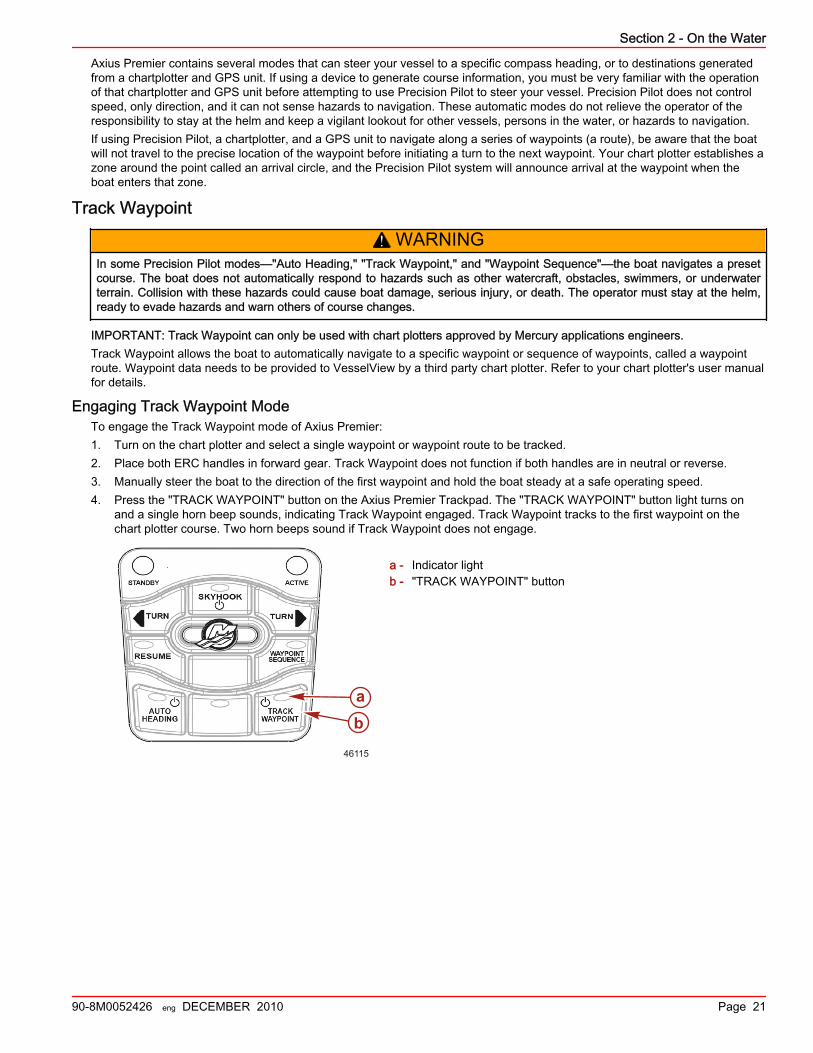
Engaging Track Waypoint ModeTo engage the Track Waypoint mode of Axius Premier:1. Turn on the chart plotter and select a single waypoint or waypoint route to be tracked.2. Place both ERC handles in forward gear. Track Waypoint does not function if both handles are in neutral or reverse.3. Manually steer the boat to the direction of the first waypoint and hold the boat steady at a safe operating speed.4. Press the "TRACK WAYPOINT" button on the Axius Premier Trackpad. The "TRACK WAYPOINT" button light turns on
and a single horn beep sounds, indicating Track Waypoint engaged. Track Waypoint tracks to the first waypoint on thechart plotter course. Two horn beeps sound if Track Waypoint does not engage.
a - Indicator lightb - "TRACK WAYPOINT" button
46115
ba
Section 2 - On the Water
Page 22 90-8M0052426 eng DECEMBER 2010
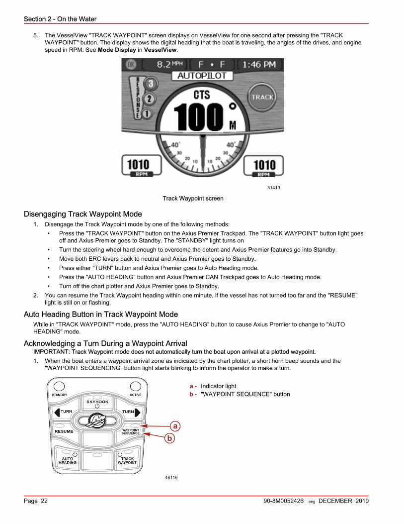
5. The VesselView "TRACK WAYPOINT" screen displays on VesselView for one second after pressing the "TRACKWAYPOINT" button. The display shows the digital heading that the boat is traveling, the angles of the drives, and enginespeed in RPM. See Mode Display in VesselView.
31413
Track Waypoint screen
Disengaging Track Waypoint Mode1. Disengage the Track Waypoint mode by one of the following methods:
• Press the "TRACK WAYPOINT" button on the Axius Premier Trackpad. The "TRACK WAYPOINT" button light goesoff and Axius Premier goes to Standby. The "STANDBY" light turns on
• Turn the steering wheel hard enough to overcome the detent and Axius Premier features go into Standby.• Move both ERC levers back to neutral and Axius Premier goes to Standby.• Press either "TURN" button and Axius Premier goes to Auto Heading mode.• Press the "AUTO HEADING" button and Axius Premier CAN Trackpad goes to Auto Heading mode.• Turn off the chart plotter and Axius Premier goes to Standby.
2. You can resume the Track Waypoint heading within one minute, if the vessel has not turned too far and the "RESUME"light is still on or flashing.
Auto Heading Button in Track Waypoint ModeWhile in "TRACK WAYPOINT" mode, press the "AUTO HEADING" button to cause Axius Premier to change to "AUTOHEADING" mode.
Acknowledging a Turn During a Waypoint ArrivalIMPORTANT: Track Waypoint mode does not automatically turn the boat upon arrival at a plotted waypoint.1. When the boat enters a waypoint arrival zone as indicated by the chart plotter, a short horn beep sounds and the
"WAYPOINT SEQUENCING" button light starts blinking to inform the operator to make a turn.
a - Indicator lightb - "WAYPOINT SEQUENCE" button
46116
ba
Section 2 - On the Water
90-8M0052426 eng DECEMBER 2010 Page 23
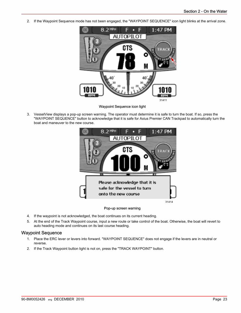
2. If the Waypoint Sequence mode has not been engaged, the "WAYPOINT SEQUENCE" icon light blinks at the arrival zone.
31411
Waypoint Sequence icon light
3. VesselView displays a pop‑up screen warning. The operator must determine it is safe to turn the boat. If so, press the"WAYPOINT SEQUENCE" button to acknowledge that it is safe for Axius Premier CAN Trackpad to automatically turn theboat and maneuver to the new course.
31414
Pop-up screen warning
4. If the waypoint is not acknowledged, the boat continues on its current heading.5. At the end of the Track Waypoint course, input a new route or take control of the boat. Otherwise, the boat will revert to
auto heading mode and continues on its last course heading.
Waypoint Sequence1. Place the ERC lever or levers into forward. "WAYPOINT SEQUENCE" does not engage if the levers are in neutral or
reverse.2. If the Track Waypoint button light is not on, press the "TRACK WAYPOINT" button.
Section 2 - On the Water
Page 24 90-8M0052426 eng DECEMBER 2010
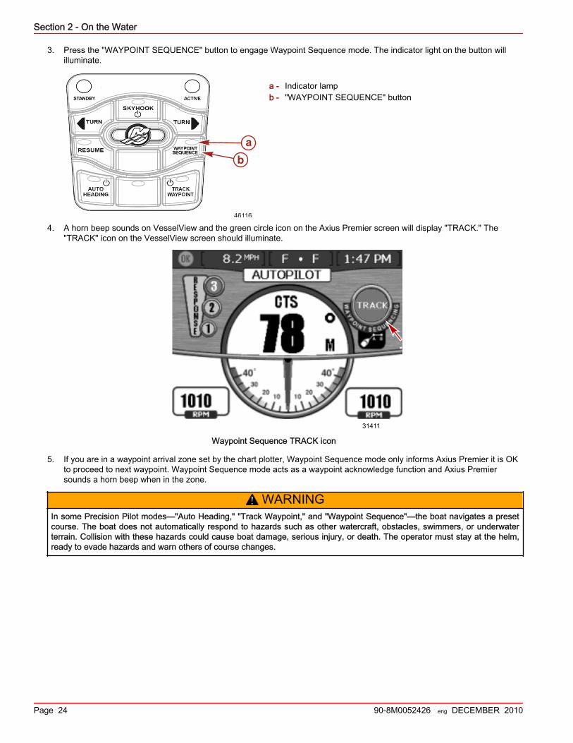
3. Press the "WAYPOINT SEQUENCE" button to engage Waypoint Sequence mode. The indicator light on the button willilluminate.
a - Indicator lampb - "WAYPOINT SEQUENCE" button
4. A horn beep sounds on VesselView and the green circle icon on the Axius Premier screen will display "TRACK." The"TRACK" icon on the VesselView screen should illuminate.
31411
Waypoint Sequence TRACK icon
5. If you are in a waypoint arrival zone set by the chart plotter, Waypoint Sequence mode only informs Axius Premier it is OKto proceed to next waypoint. Waypoint Sequence mode acts as a waypoint acknowledge function and Axius Premiersounds a horn beep when in the zone.
! WARNINGIn some Precision Pilot modes—"Auto Heading," "Track Waypoint," and "Waypoint Sequence"—the boat navigates a presetcourse. The boat does not automatically respond to hazards such as other watercraft, obstacles, swimmers, or underwaterterrain. Collision with these hazards could cause boat damage, serious injury, or death. The operator must stay at the helm,ready to evade hazards and warn others of course changes.
46116
ba

Section 2 - On the Water
90-8M0052426 eng DECEMBER 2010 Page 25
6. Stay alert; the boat turns automatically in this mode. The operator must know if it is safe to turn when the vessel is enteringa waypoint arrival zone. Inform passengers that the boat automatically turns so they can be prepared.
31414
Waypoint acknowledge screen
7. If you are not in a previously set waypoint arrival zone, "WAYPOINT SEQUENCE" mode starts auto sequencing to thewaypoints in the route. Acknowledge that you understand the information presented by the pop‑up screen warning andpress the enter button—the button with a check mark symbol.
31412
Pop-up screen warning
8. Press the "TRACK WAYPOINT" button. The "WAYPOINT SEQUENCE" button light turns on and a single horn beepsounds.
9. Press the "TRACK WAYPOINT" button a second time to put Axius Premier in Standby mode. All lights other than"STANDBY" turn off.
Cruise ControlThe VesselView system features integrated throttle cruise control (cruise), which allows the operator to limit the peak RPM ofchoice below Wide Open Throttle (WOT). This feature requires VesselView. Refer to the owner's manual provided with yourVesselView for operation instructions.These additional notes are exclusive to your package:• You can change or disengage cruise through the screen at any time.• Cruise resets when the key is turned off.• If the cruise limit is changed while the levers are at WOT, cruise gradually changes to the new speed.
Section 2 - On the Water
Page 26 90-8M0052426 eng DECEMBER 2010
• Cruise does not disengage if the ERC levers are at a higher engine speed than the actual RPM. Bring the levers back tothe forward detent to disengage.
Dual Helm (If Equipped)Dual‑Helm Station Transfer
NOTE: Transfer will not activate if the joystick stick is in operation. due to not allowing helm transfer while in gear .The "TRANSFER" button allows the boat operator to transfer control of the boat from the active helm to the inactive helm. Havean operator at each helm during transfer in case the transfer is not successful. The transfer can only be accomplished when theERC levers at both helms are in the neutral position. All engaged DTS functions carry over to the new active helm, but are notactive because the boat is in neutral. Most Axius and Axius Premier functions that are engaged at the active helm will remainengaged, but not active due to the boat being in neutral. Skyhook, however, will turn off upon transfer, but can be engagedagain at the new helm. The memory in the chartplotter at the active helm will be shared with the new helm if the new helm isequipped with a chartplotter. Helms without chartplotters lose the ability to use Track and Waypoint Sequence at that helm.The ACTIVE light on the Axius touchpad is illuminated at the station that is in control of the boat.The following functions carry over in their current state when the helm is transferred:
DTSNOTE: The following features will remain on if they were on, although they will not be active until the ERC levers are moved outof neutral.1. DOCK2. THROTTLE ONLY3. 1‑LEVER
AxiusNOTE: Auto heading requires that the boat be in gear and moving to engage. It will not be active during transfer as all controlsmust be in the Neutral position.
! WARNINGAvoid serious injury or death from loss of boat control. The boat operator should never leave the active station while engine isin gear. Helm transfer should only be attempted while both stations are manned. One‑person helm transfer should only beperformed while engine is in neutral.
NOTE: Neutral position is required when doing a station transfer. If conditions do not allow the remote control to be placed inneutral position the transfer can not be completed.NOTE: Pressing and releasing the TRANSFER button at new station allows the engine control to be transferred to the newstation. Disable any engaged Axius and Axius premier functions.1. Place active remote control lever to neutral position.2. Have a capable operator at the inactive helm station and position remote control lever to the neutral position.3. Communicate to the operator at the inactive helm that the transfer is ready to take place. Press the TRANSFER button on
the inactive helm once to initiate and match lever demand. Move the levers as necessary to match the demand.
Section 2 - On the Water
90-8M0052426 eng DECEMBER 2010 Page 27
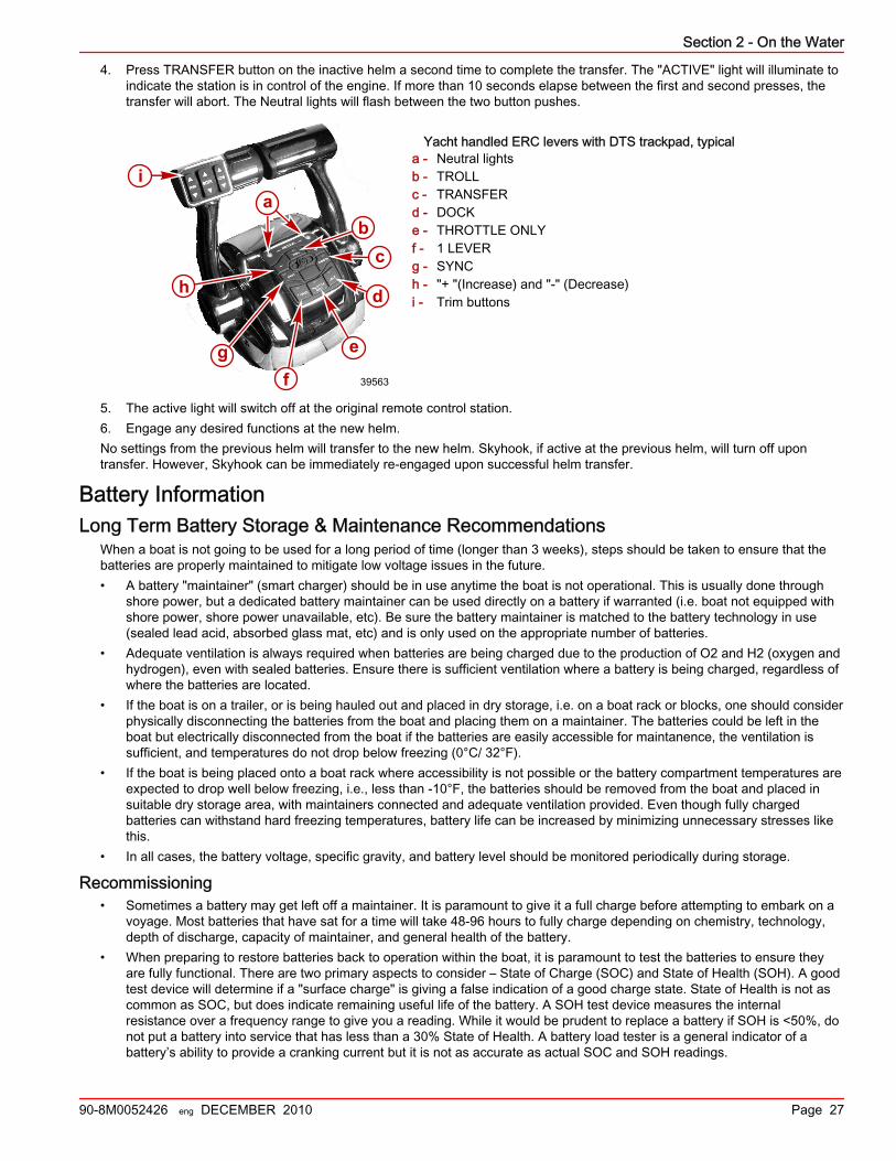
4. Press TRANSFER button on the inactive helm a second time to complete the transfer. The "ACTIVE" light will illuminate toindicate the station is in control of the engine. If more than 10 seconds elapse between the first and second presses, thetransfer will abort. The Neutral lights will flash between the two button pushes.
Yacht handled ERC levers with DTS trackpad, typicala - Neutral lightsb - TROLLc - TRANSFERd - DOCKe - THROTTLE ONLYf - 1 LEVERg - SYNCh - "+ "(Increase) and "‑" (Decrease)i - Trim buttons
5. The active light will switch off at the original remote control station.6. Engage any desired functions at the new helm.No settings from the previous helm will transfer to the new helm. Skyhook, if active at the previous helm, will turn off upontransfer. However, Skyhook can be immediately re‑engaged upon successful helm transfer.
Battery InformationLong Term Battery Storage & Maintenance Recommendations
When a boat is not going to be used for a long period of time (longer than 3 weeks), steps should be taken to ensure that thebatteries are properly maintained to mitigate low voltage issues in the future.• A battery "maintainer" (smart charger) should be in use anytime the boat is not operational. This is usually done through
shore power, but a dedicated battery maintainer can be used directly on a battery if warranted (i.e. boat not equipped withshore power, shore power unavailable, etc). Be sure the battery maintainer is matched to the battery technology in use(sealed lead acid, absorbed glass mat, etc) and is only used on the appropriate number of batteries.
• Adequate ventilation is always required when batteries are being charged due to the production of O2 and H2 (oxygen andhydrogen), even with sealed batteries. Ensure there is sufficient ventilation where a battery is being charged, regardless ofwhere the batteries are located.
• If the boat is on a trailer, or is being hauled out and placed in dry storage, i.e. on a boat rack or blocks, one should considerphysically disconnecting the batteries from the boat and placing them on a maintainer. The batteries could be left in theboat but electrically disconnected from the boat if the batteries are easily accessible for maintanence, the ventilation issufficient, and temperatures do not drop below freezing (0°C/ 32°F).
• If the boat is being placed onto a boat rack where accessibility is not possible or the battery compartment temperatures areexpected to drop well below freezing, i.e., less than ‑10°F, the batteries should be removed from the boat and placed insuitable dry storage area, with maintainers connected and adequate ventilation provided. Even though fully chargedbatteries can withstand hard freezing temperatures, battery life can be increased by minimizing unnecessary stresses likethis.
• In all cases, the battery voltage, specific gravity, and battery level should be monitored periodically during storage.
Recommissioning• Sometimes a battery may get left off a maintainer. It is paramount to give it a full charge before attempting to embark on a
voyage. Most batteries that have sat for a time will take 48‑96 hours to fully charge depending on chemistry, technology,depth of discharge, capacity of maintainer, and general health of the battery.
• When preparing to restore batteries back to operation within the boat, it is paramount to test the batteries to ensure theyare fully functional. There are two primary aspects to consider – State of Charge (SOC) and State of Health (SOH). A goodtest device will determine if a "surface charge" is giving a false indication of a good charge state. State of Health is not ascommon as SOC, but does indicate remaining useful life of the battery. A SOH test device measures the internalresistance over a frequency range to give you a reading. While it would be prudent to replace a battery if SOH is <50%, donot put a battery into service that has less than a 30% State of Health. A battery load tester is a general indicator of abattery’s ability to provide a cranking current but it is not as accurate as actual SOC and SOH readings.
ia
bc
d
e
fg
h
a
39563
Section 2 - On the Water
Page 28 90-8M0052426 eng DECEMBER 2010
• Another item of consideration is the quality of the connections being made to the batteries. Inspect for corrosion and poorterminal connections (crimp, corrosion, strand breakage, etc) prior to restoring batteries to full operation. As required,ensure battery cells have adequate electrolyte fluid levels (use only distilled water and no metal funnels!) and use asilicone grease on the battery post terminals.
Contingent OperationsPort Engine–Only Operation
The force feedback feature of the steering wheel is only available when the starboard key switch is in the on position. If thestarboard key switch is off or there has been damage to the starboard electrical system, the port control system monitors thesteering wheel.If only the port side is operational, or only the port key switch is in the on position, the force feedback system will not provideend stops for the steering wheel. In this case, the drive will turn in the direction of steering wheel rotation until the mechanicallimits of the drive are reached.NOTE: If the port electrical system is damaged, the steering wheel will operate normally with complete force feedback and endstops.Note that joystick is not available in single‑engine operation. However, Axius features redundant trackpad systems, so AutoHeading mode is still available during single‑engine operation.
Axius Shift Override—Emergency ProcedureIf the VesselView display shows the error message "GEAR POS DIFF" and an engine will not start or will not shift into gear,there is a problem with the Electronic Shift Control (ESC) system. If one drive is working, you may operate on one engine anddrive.
! CAUTIONUsing the emergency procedure to manually shift the drive disengages shift control at the helm. To avoid damage or injury,drive cautiously when a gear is engaged manually. To stop the drive and its propeller, you must turn the key switch to the offposition.
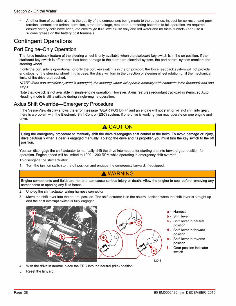
You can disengage the shift actuator to manually shift the drive into neutral for starting and into forward gear position foroperation. Engine speed will be limited to 1000–1200 RPM while operating in emergency shift override.To disengage the shift actuator:1. Turn the ignition switch to the off position and engage the emergency lanyard, if equipped.
! WARNINGEngine components and fluids are hot and can cause serious injury or death. Allow the engine to cool before removing anycomponents or opening any fluid hoses.
2. Unplug the shift actuator wiring harness connector.3. Move the shift lever into the neutral position. The shift actuator is in the neutral position when the shift lever is straight up
and the shift interrupt switch is fully engaged.
a - Harnessb - Shift leverc - Shift lever in neutral
positiond - Shift lever in forward
positione - Shift lever in reverse
positionf - Gear position indicator
switch
4. With the drive in neutral, place the ERC into the neutral (idle) position.5. Reset the lanyard.
N
FR
a
b
d
e
32243
f
c
YY
Section 2 - On the Water
90-8M0052426 eng DECEMBER 2010 Page 29
! WARNINGA spinning propeller, a moving boat, or any solid device attached to the boat can cause serious injury or death to swimmers.Stop the engine immediately whenever anyone in the water is near your boat.
6. Ensure that no one is in the water near the boat, then start the engine.7. With the engine running at idle speed, the drive can be shifted into gear and out of gear by manually moving the shift lever.
NOTE: Engine speed will be limited to 1000–1200 RPM while operating in emergency shift override. The Auto Headingfeature using the Axius track pad will still function but is limited to this reduced RPM setting.IMPORTANT: The boat's stopping distance increases during manual gear engagement operation.
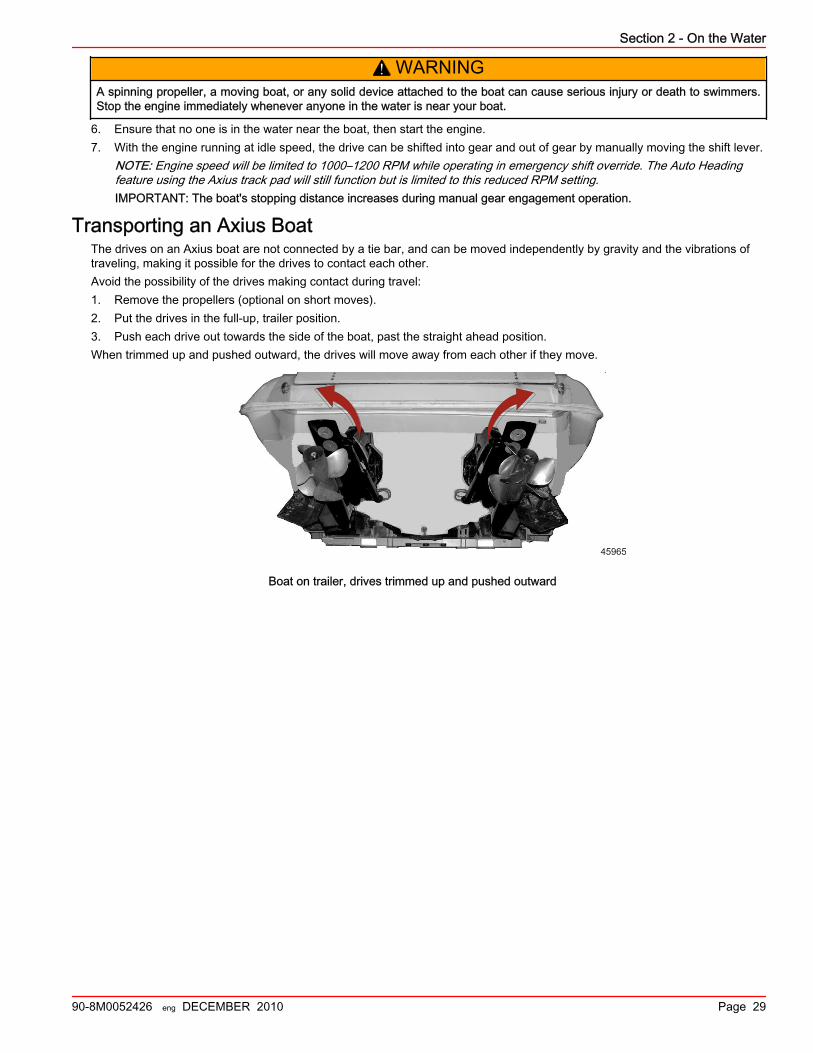
Transporting an Axius BoatThe drives on an Axius boat are not connected by a tie bar, and can be moved independently by gravity and the vibrations oftraveling, making it possible for the drives to contact each other.Avoid the possibility of the drives making contact during travel:1. Remove the propellers (optional on short moves).2. Put the drives in the full‑up, trailer position.3. Push each drive out towards the side of the boat, past the straight ahead position.When trimmed up and pushed outward, the drives will move away from each other if they move.
45965
Boat on trailer, drives trimmed up and pushed outward

Section 2 - On the Water
Notes:
Page 30 90-8M0052426 eng DECEMBER 2010

Section 3 - Troubleshooting
90-8M0052426 eng DECEMBER 2010 Page 31
Section 3 - TroubleshootingTable of ContentsCheck VesselView First........................................................ 32Diagnosing DTS Problems................................................... 32Engine Guardian System...................................................... 32Troubleshooting Charts........................................................ 32
Joystick.......................................................................... 32
Electronic Remote Controls........................................... 33Steering System............................................................ 34Trackpad Features.........................................................34Auto Pilot....................................................................... 34Skyhook......................................................................... 35 3
Section 3 - Troubleshooting
Page 32 90-8M0052426 eng DECEMBER 2010
Check VesselView FirstYour VesselView display is the primary information source for the various functions of your boat. Consult the VesselViewdisplay if you suspect something is wrong. VesselView displays faults and other information that can be helpful in determiningthe current status of various systems that could be causing your concern and the solution to the problem.
Diagnosing DTS ProblemsYour authorized Mercury MerCruiser dealer has the proper service tools for diagnosing problems on Digital Throttle and Shift(DTS) Systems. The Electronic Control Module (ECM)/Propulsion Control Module (PCM) on these engines has the ability todetect some problems with the system when they occur, and store a Trouble Code in the ECM/PCM's memory. This code canthen be read later by a service technician using a special diagnostic tool.
Engine Guardian SystemThe Engine Guardian System monitors the critical sensors on the engine for any early indications of problems. The system willrespond to a problem by emitting a continuous beep and/or reducing engine power in order to provide engine protection.If Guardian System has been activated, reduce throttle speed. The horn will turn off when throttle speed is within the allowablelimit. Consult an authorized Mercury MerCruiser dealer for assistance.
Troubleshooting ChartsJoystick
Symptom Remedy
The joystick does not control the boat.One or both remote controls are not in neutral. Put both remote controlsin neutral.
One or both engines are not running. Start the engine or engines.
Response to joystick input is erratic, or the joystickoperates independent of input.
Ensure there are no radios or other sources of electronic or magneticinterference near the joystick.
The joystick does not function properly and a faultcode is set.
Check VesselView for Guardian fault codes that indicate reducedengine power. If found, have the system checked by your authorizedMercury MerCruiser dealer.
The joystick operates eratically. Check trim position. Trim drives down.
The joystick operates too agressively Activate Dock mode.
Section 3 - Troubleshooting
90-8M0052426 eng DECEMBER 2010 Page 33
Electronic Remote ControlsSymptom Remedy
The ERC (electronic remote control) lever is too hard ortoo easy to move out of neutral detent.
Adjust detent tension. See Section 1, Dual Handle ElectronicRemote Control with DTS Trackpad Features and Operation .
The ERC lever has too much or too little resistancethrough its range of motion.
Adjust the handle tension screw. See Section 1, Dual HandleElectronic Remote Control with DTS Trackpad Features andOperation .
The ERC lever increases engine RPM, but the enginesdo not engage gears and the boat does not move.
Key off and key on.
Check the "Throttle Only" button on the DTS trackpad. Put theERC levers in neutral and push the button to disengage, if thelight is on.
Engage gears manually. See Section 2, Axius Shift Override—Emergency Procedure.
Contact your authorized Mercury MerCruiser dealer.
The ERC lever controls the engine and drive, but doesnot reach wide open throttle.
If the engine only reaches 50% of WOT, check the "DOCKING"button on the DTS trackpad. Put the handles in neutral and pushthe button to disengage, if light is on.
Check VesselView to see if cruise control is enabled. Disablecruise control.
Check for damage to the propeller. If found, contact yourauthorized Mercury MerCruiser service technician to ask if thepropellers need to be repaired or changed.
Check VesselView for Guardian fault codes that indicate reducedengine power. If found, contact your authorized MercuryMerCruiser dealer.
The ERC lever controls the engine and drive, but doesnot respond in a linear manner.
Check the "TROLL" button on the DTS track pad. If light is on, putthe handles in Neutral and push the "TROLL" button todisengage,
Check whether dock mode or cruise control are on. If on, turn offor disengage.
When one ERC lever is moved, both engines respond.Check the "1 LEVER" button on the DTS track pad. If the light ison, put the handles in neutral and push the "1 LEVER" button todisengage.
The ERC control, joystick, and steering wheel do notfunction.
Press "TRANSFER" on DTS track pad to restore helm control.(Multiple helm boats only.)
Boat goes forward but will not go backwards quickly. Trim drives down.
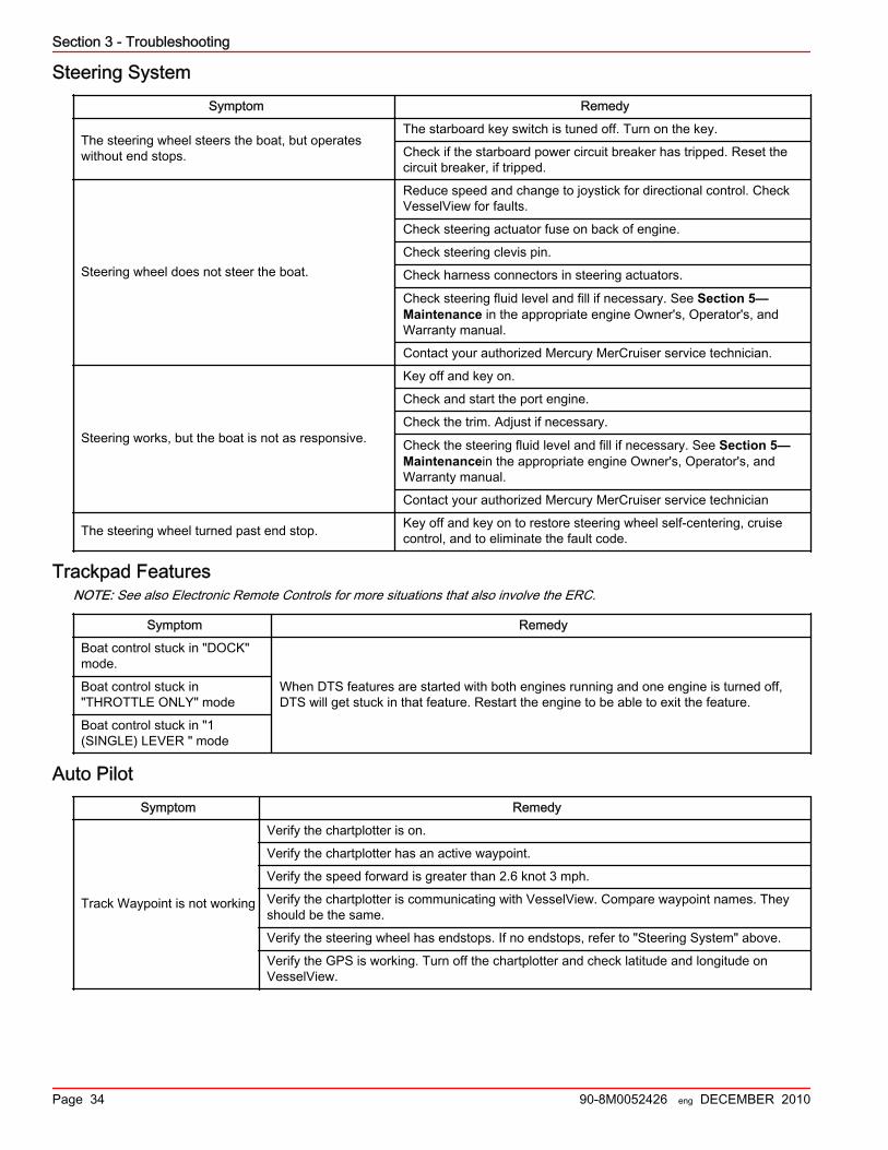
Section 3 - Troubleshooting
Page 34 90-8M0052426 eng DECEMBER 2010
Steering SystemSymptom Remedy
The steering wheel steers the boat, but operateswithout end stops.
The starboard key switch is tuned off. Turn on the key.
Check if the starboard power circuit breaker has tripped. Reset thecircuit breaker, if tripped.
Steering wheel does not steer the boat.
Reduce speed and change to joystick for directional control. CheckVesselView for faults.
Check steering actuator fuse on back of engine.
Check steering clevis pin.
Check harness connectors in steering actuators.
Check steering fluid level and fill if necessary. See Section 5—Maintenance in the appropriate engine Owner's, Operator's, andWarranty manual.
Contact your authorized Mercury MerCruiser service technician.
Steering works, but the boat is not as responsive.
Key off and key on.
Check and start the port engine.
Check the trim. Adjust if necessary.
Check the steering fluid level and fill if necessary. See Section 5—Maintenancein the appropriate engine Owner's, Operator's, andWarranty manual.
Contact your authorized Mercury MerCruiser service technician
The steering wheel turned past end stop. Key off and key on to restore steering wheel self‑centering, cruisecontrol, and to eliminate the fault code.
Trackpad FeaturesNOTE: See also Electronic Remote Controls for more situations that also involve the ERC.
Symptom Remedy
Boat control stuck in "DOCK"mode.
When DTS features are started with both engines running and one engine is turned off,DTS will get stuck in that feature. Restart the engine to be able to exit the feature.
Boat control stuck in"THROTTLE ONLY" mode
Boat control stuck in "1(SINGLE) LEVER " mode
Auto PilotSymptom Remedy
Track Waypoint is not working
Verify the chartplotter is on.
Verify the chartplotter has an active waypoint.
Verify the speed forward is greater than 2.6 knot 3 mph.
Verify the chartplotter is communicating with VesselView. Compare waypoint names. Theyshould be the same.
Verify the steering wheel has endstops. If no endstops, refer to "Steering System" above.
Verify the GPS is working. Turn off the chartplotter and check latitude and longitude onVesselView.

Section 3 - Troubleshooting
90-8M0052426 eng DECEMBER 2010 Page 35
SkyhookSymptom Remedy
Skyhook does not work
Ensure that Skyhook is enabled by the vessel personality.
Is VesselView on? VesselView must be turned on for Skyhook to function.
Is the GPS working? If locked, cycle keys.

Section 3 - Troubleshooting
Notes:
Page 36 90-8M0052426 eng DECEMBER 2010
Section 4 - Customer Assistance Information
90-8M0052426 eng DECEMBER 2010 Page 37
Section 4 - Customer Assistance InformationTable of ContentsOwner Service Assistance.................................................... 38
Local Repair Service .................................................... 38Service Away From Home ............................................ 38Stolen Power Package ................................................. 38Attention Required After Submersion ........................... 38Replacement Service Parts .......................................... 38
Parts and Accessories Inquiries ............................ 38
Resolving a Problem .................................................... 38Contact Information for Mercury Marine CustomerService ......................................................................... 39
Ordering Literature............................................................... 39United States and Canada ........................................... 39Outside the United States and Canada ........................ 40
4
Section 4 - Customer Assistance Information
Page 38 90-8M0052426 eng DECEMBER 2010
Owner Service AssistanceLocal Repair Service
If you need service for your Mercury MerCruiser–powered boat, take it to your authorized dealer. Only authorized dealersspecialize in Mercury MerCruiser products and have factory‑trained mechanics, special tools and equipment, and genuineQuicksilver parts and accessories to properly service your engine.NOTE: Quicksilver parts and accessories are engineered and built by Mercury Marine specifically for Mercury MerCruisersterndrives and inboards.
Service Away From HomeIf you are away from your local dealer and the need arises for service, contact the nearest authorized dealer. Refer to theYellow Pages of the telephone directory. If, for any reason, you cannot obtain service, contact the nearest Regional ServiceCenter. Outside the United States and Canada, contact the nearest Marine Power International Service Center.
Stolen Power PackageIf your power package is stolen, immediately advise the local authorities and Mercury Marine of the model and serial numbersand to whom the recovery is to be reported. This information is maintained in a database at Mercury Marine to aid authoritiesand dealers in recovery of stolen power packages.
Attention Required After Submersion1. Before recovery, contact an authorized Mercury MerCruiser dealer.2. After recovery, immediate service by an authorized Mercury MerCruiser dealer is required to reduce the possibility of
serious engine damage.
Replacement Service Parts
! WARNINGAvoid fire or explosion hazard. Electrical, ignition, and fuel system components on Mercury Marine products comply withfederal and international standards to minimize risk of fire or explosion. Do not use replacement electrical or fuel systemcomponents that do not comply with these standards. When servicing the electrical and fuel systems, properly install andtighten all components.
Marine engines are expected to operate at or near full throttle for most of their life. They are also expected to operate in bothfresh and saltwater environments. These conditions require numerous special parts. Exercise care when replacing marineengine parts, because specifications are different from those of the standard automotive engine. For example, one of the mostimportant special replacement parts, is the cylinder head gasket. Marine engines cannot use steel‑type automotive headgaskets because saltwater is highly corrosive. A marine engine head gasket uses special materials to resist corrosion.Because marine engines must be capable of running at or near maximum RPM much of the time, they also have special valvesprings, valve lifters, pistons, bearings, camshafts and other heavy‑duty moving parts.Mercury MerCruiser marine engines have other special modifications to provide long life and dependable performance.
Parts and Accessories InquiriesDirect any inquiries concerning Quicksilver replacement parts and accessories to your local authorized dealer. The dealer hasthe necessary information to order parts and accessories for you if they are not in stock. Only authorized dealers can purchasegenuine Quicksilver parts and accessories from the factory. Mercury Marine does not sell to unauthorized dealers or retailcustomers. When inquiring on parts and accessories, the dealer requires the engine model and serial numbers to order thecorrect parts.
Resolving a ProblemSatisfaction with your Mercury MerCruiser product is very important to your dealer and to us. If you ever have a problem,question or concern about your power package, contact your dealer or any authorized Mercury MerCruiser dealership. If youneed additional assistance:1. Talk with the dealership's sales manager or service manager. Contact the owner of the dealership if the sales manager and
service manager have been unable to resolve the problem.2. If your question, concern, or problem cannot be resolved by your dealership, please contact Mercury Marine Service Office
for assistance. Mercury Marine will work with you and your dealership to resolve all problems.The following information will be needed by the Customer Service:• Your name and address
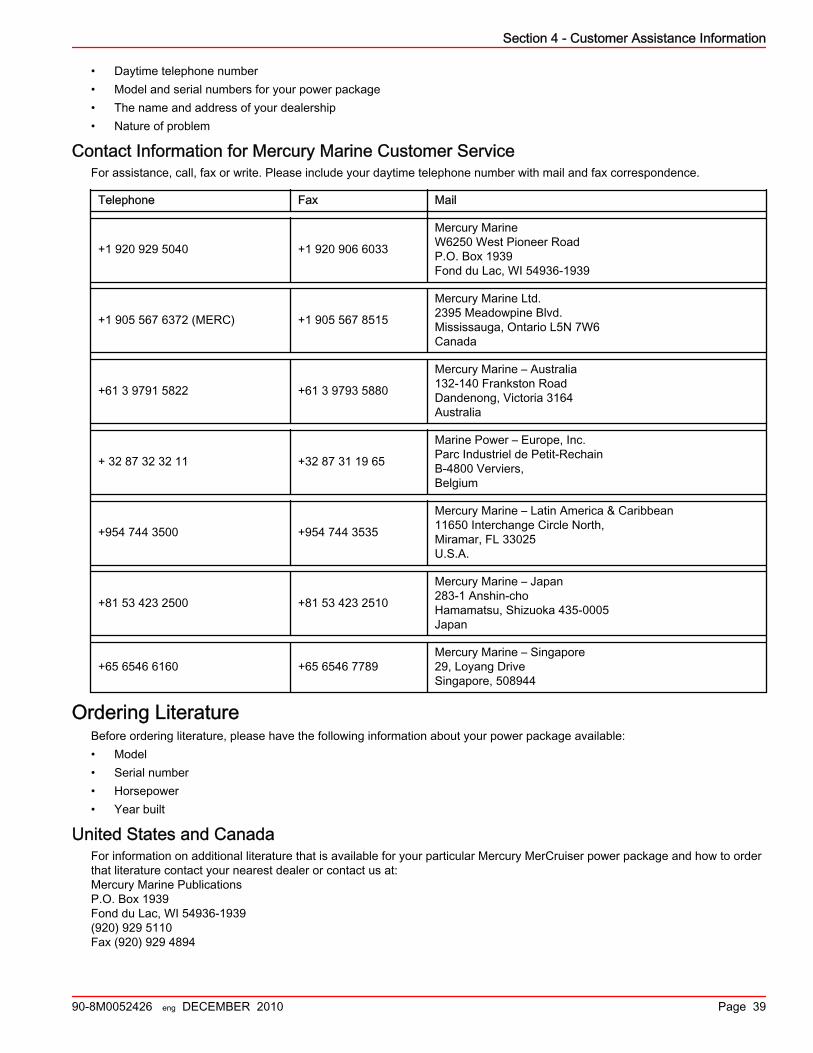
Section 4 - Customer Assistance Information
90-8M0052426 eng DECEMBER 2010 Page 39
• Daytime telephone number• Model and serial numbers for your power package• The name and address of your dealership• Nature of problem
Contact Information for Mercury Marine Customer ServiceFor assistance, call, fax or write. Please include your daytime telephone number with mail and fax correspondence.
Telephone Fax Mail
+1 920 929 5040 +1 920 906 6033
Mercury MarineW6250 West Pioneer RoadP.O. Box 1939Fond du Lac, WI 54936-1939
+1 905 567 6372 (MERC) +1 905 567 8515
Mercury Marine Ltd.2395 Meadowpine Blvd.Mississauga, Ontario L5N 7W6Canada
+61 3 9791 5822 +61 3 9793 5880
Mercury Marine – Australia132-140 Frankston RoadDandenong, Victoria 3164Australia
+ 32 87 32 32 11 +32 87 31 19 65
Marine Power – Europe, Inc.Parc Industriel de Petit-RechainB-4800 Verviers,Belgium
+954 744 3500 +954 744 3535
Mercury Marine – Latin America & Caribbean11650 Interchange Circle North,Miramar, FL 33025U.S.A.
+81 53 423 2500 +81 53 423 2510
Mercury Marine – Japan283-1 Anshin-choHamamatsu, Shizuoka 435-0005Japan
+65 6546 6160 +65 6546 7789Mercury Marine – Singapore29, Loyang DriveSingapore, 508944
Ordering LiteratureBefore ordering literature, please have the following information about your power package available:• Model• Serial number• Horsepower• Year built
United States and CanadaFor information on additional literature that is available for your particular Mercury MerCruiser power package and how to orderthat literature contact your nearest dealer or contact us at:Mercury Marine PublicationsP.O. Box 1939Fond du Lac, WI 54936-1939(920) 929 5110Fax (920) 929 4894

Section 4 - Customer Assistance Information
Page 40 90-8M0052426 eng DECEMBER 2010
Outside the United States and CanadaContact your nearest dealer or Marine Power Service Center for information on additional literature that is available for yourparticular Mercury MerCruiser power package and how to order that literature.Print or type your mailing address, which be used as your shipping label, and include your order and payment. Mail to:Mercury MarineAttn: Publications DepartmentW6250 West Pioneer RoadP.O. Box 1939Fond du Lac, WI 54936-1939USA

Section 5 - Predelivery (PDI) and Customer Delivery (CDI) Checklists
90-8M0052426 eng DECEMBER 2010 Page 41
Section 5 - Predelivery (PDI) and Customer Delivery(CDI) Checklists
Table of ContentsPredelivery Inspection (PDI)................................................. 42 Customer Delivery Inspection (CDI)..................................... 44
5
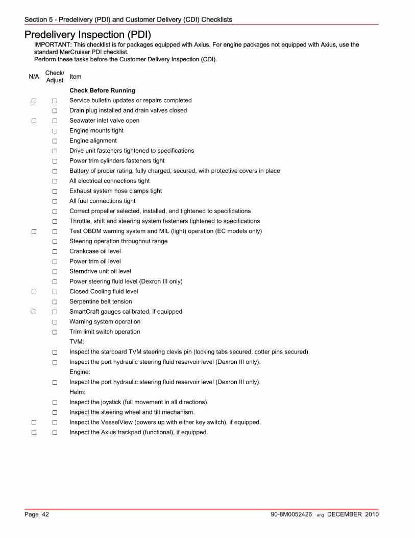
Section 5 - Predelivery (PDI) and Customer Delivery (CDI) Checklists
Page 42 90-8M0052426 eng DECEMBER 2010
Predelivery Inspection (PDI)IMPORTANT: This checklist is for packages equipped with Axius. For engine packages not equipped with Axius, use thestandard MerCruiser PDI checklist.Perform these tasks before the Customer Delivery Inspection (CDI).
N/A Check/Adjust Item
Check Before Running⃞ ⃞ Service bulletin updates or repairs completed
⃞ Drain plug installed and drain valves closed⃞ ⃞ Seawater inlet valve open
⃞ Engine mounts tight⃞ Engine alignment⃞ Drive unit fasteners tightened to specifications⃞ Power trim cylinders fasteners tight⃞ Battery of proper rating, fully charged, secured, with protective covers in place⃞ All electrical connections tight⃞ Exhaust system hose clamps tight⃞ All fuel connections tight⃞ Correct propeller selected, installed, and tightened to specifications⃞ Throttle, shift and steering system fasteners tightened to specifications
⃞ ⃞ Test OBDM warning system and MIL (light) operation (EC models only)⃞ Steering operation throughout range⃞ Crankcase oil level⃞ Power trim oil level⃞ Sterndrive unit oil level⃞ Power steering fluid level (Dexron III only)
⃞ ⃞ Closed Cooling fluid level⃞ Serpentine belt tension
⃞ ⃞ SmartCraft gauges calibrated, if equipped⃞ Warning system operation⃞ Trim limit switch operation
TVM:⃞ Inspect the starboard TVM steering clevis pin (locking tabs secured, cotter pins secured).⃞ Inspect the port hydraulic steering fluid reservoir level (Dexron III only).
Engine:⃞ Inspect the port hydraulic steering fluid reservoir level (Dexron III only).
Helm:⃞ Inspect the joystick (full movement in all directions).⃞ Inspect the steering wheel and tilt mechanism.
⃞ ⃞ Inspect the VesselView (powers up with either key switch), if equipped.⃞ ⃞ Inspect the Axius trackpad (functional), if equipped.
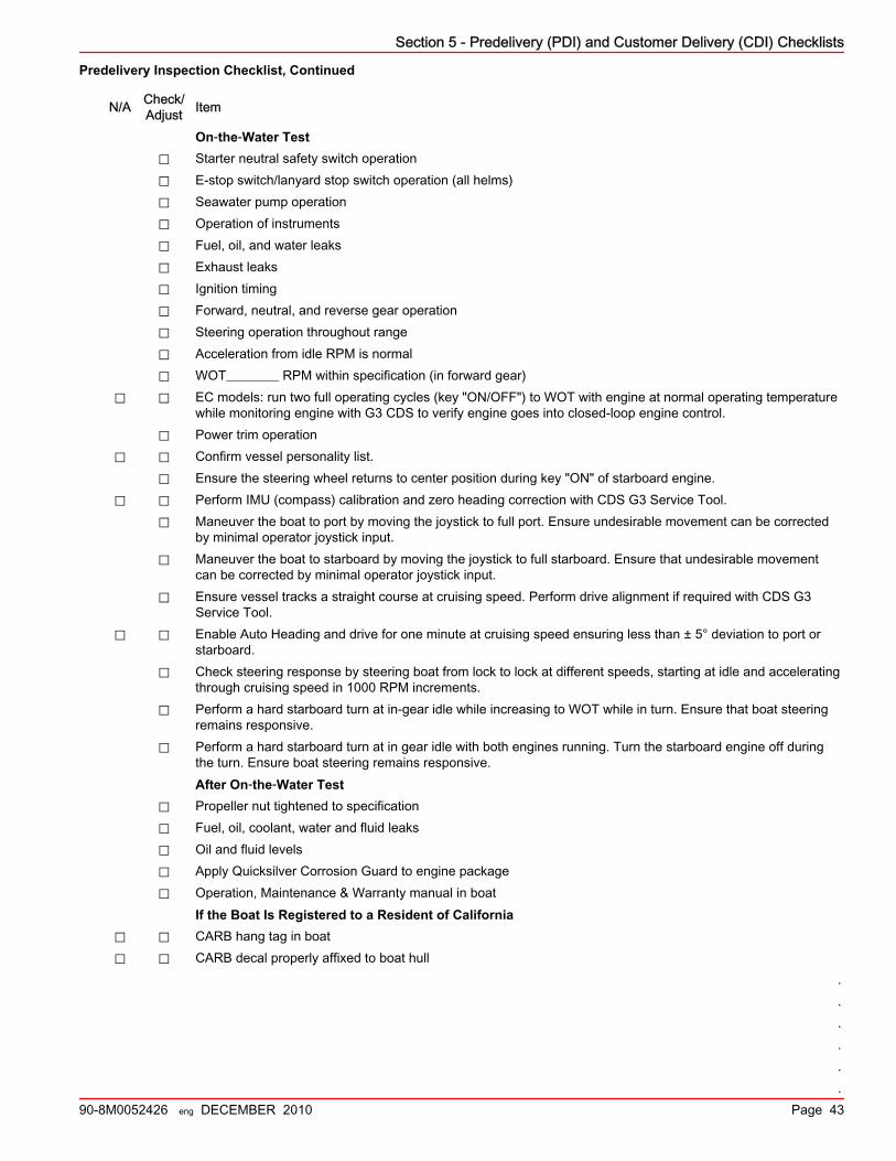
Section 5 - Predelivery (PDI) and Customer Delivery (CDI) Checklists
90-8M0052426 eng DECEMBER 2010 Page 43
Predelivery Inspection Checklist, Continued
N/A Check/Adjust Item
On‑the‑Water Test⃞ Starter neutral safety switch operation⃞ E‑stop switch/lanyard stop switch operation (all helms)⃞ Seawater pump operation⃞ Operation of instruments⃞ Fuel, oil, and water leaks⃞ Exhaust leaks⃞ Ignition timing⃞ Forward, neutral, and reverse gear operation⃞ Steering operation throughout range⃞ Acceleration from idle RPM is normal⃞ WOT________ RPM within specification (in forward gear)
⃞ ⃞ EC models: run two full operating cycles (key "ON/OFF") to WOT with engine at normal operating temperaturewhile monitoring engine with G3 CDS to verify engine goes into closed‑loop engine control.
⃞ Power trim operation⃞ ⃞ Confirm vessel personality list.
⃞ Ensure the steering wheel returns to center position during key "ON" of starboard engine.⃞ ⃞ Perform IMU (compass) calibration and zero heading correction with CDS G3 Service Tool.
⃞ Maneuver the boat to port by moving the joystick to full port. Ensure undesirable movement can be correctedby minimal operator joystick input.
⃞ Maneuver the boat to starboard by moving the joystick to full starboard. Ensure that undesirable movementcan be corrected by minimal operator joystick input.
⃞ Ensure vessel tracks a straight course at cruising speed. Perform drive alignment if required with CDS G3Service Tool.
⃞ ⃞ Enable Auto Heading and drive for one minute at cruising speed ensuring less than ± 5° deviation to port orstarboard.
⃞ Check steering response by steering boat from lock to lock at different speeds, starting at idle and acceleratingthrough cruising speed in 1000 RPM increments.
⃞ Perform a hard starboard turn at in‑gear idle while increasing to WOT while in turn. Ensure that boat steeringremains responsive.
⃞ Perform a hard starboard turn at in gear idle with both engines running. Turn the starboard engine off duringthe turn. Ensure boat steering remains responsive.After On‑the‑Water Test
⃞ Propeller nut tightened to specification⃞ Fuel, oil, coolant, water and fluid leaks⃞ Oil and fluid levels⃞ Apply Quicksilver Corrosion Guard to engine package⃞ Operation, Maintenance & Warranty manual in boat
If the Boat Is Registered to a Resident of California⃞ ⃞ CARB hang tag in boat⃞ ⃞ CARB decal properly affixed to boat hull
.
.
.
.
.
.
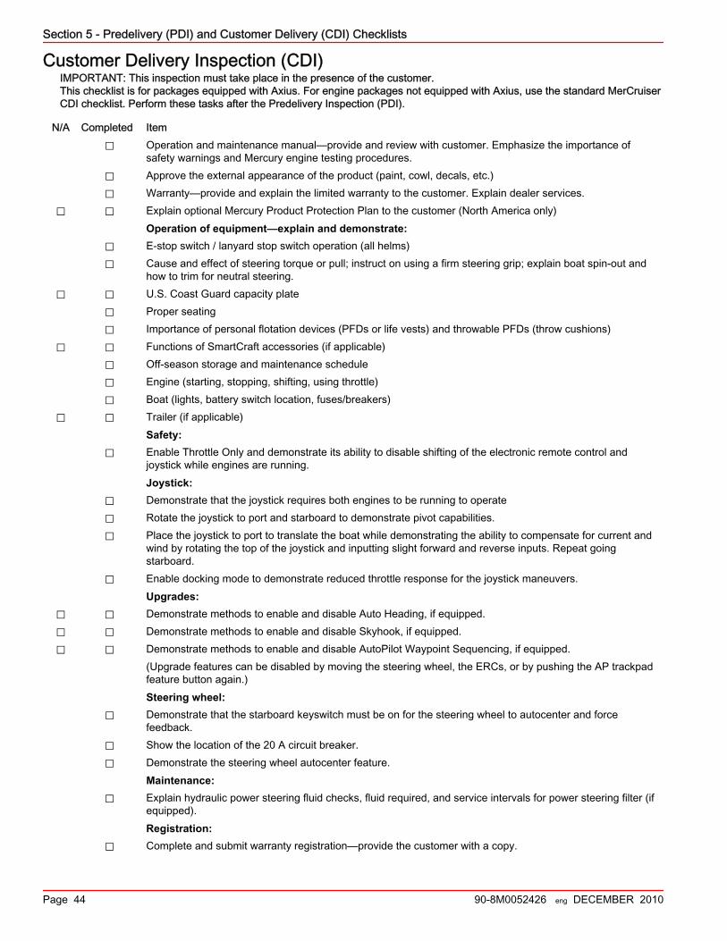
Section 5 - Predelivery (PDI) and Customer Delivery (CDI) Checklists
Page 44 90-8M0052426 eng DECEMBER 2010
Customer Delivery Inspection (CDI)IMPORTANT: This inspection must take place in the presence of the customer.This checklist is for packages equipped with Axius. For engine packages not equipped with Axius, use the standard MerCruiserCDI checklist. Perform these tasks after the Predelivery Inspection (PDI).
N/A Completed Item⃞ Operation and maintenance manual—provide and review with customer. Emphasize the importance of
safety warnings and Mercury engine testing procedures.⃞ Approve the external appearance of the product (paint, cowl, decals, etc.)⃞ Warranty—provide and explain the limited warranty to the customer. Explain dealer services.
⃞ ⃞ Explain optional Mercury Product Protection Plan to the customer (North America only)Operation of equipment—explain and demonstrate:
⃞ E‑stop switch / lanyard stop switch operation (all helms)⃞ Cause and effect of steering torque or pull; instruct on using a firm steering grip; explain boat spin‑out and
how to trim for neutral steering.⃞ ⃞ U.S. Coast Guard capacity plate
⃞ Proper seating⃞ Importance of personal flotation devices (PFDs or life vests) and throwable PFDs (throw cushions)
⃞ ⃞ Functions of SmartCraft accessories (if applicable)⃞ Off‑season storage and maintenance schedule⃞ Engine (starting, stopping, shifting, using throttle)⃞ Boat (lights, battery switch location, fuses/breakers)
⃞ ⃞ Trailer (if applicable)Safety:
⃞ Enable Throttle Only and demonstrate its ability to disable shifting of the electronic remote control andjoystick while engines are running.Joystick:
⃞ Demonstrate that the joystick requires both engines to be running to operate⃞ Rotate the joystick to port and starboard to demonstrate pivot capabilities.⃞ Place the joystick to port to translate the boat while demonstrating the ability to compensate for current and
wind by rotating the top of the joystick and inputting slight forward and reverse inputs. Repeat goingstarboard.
⃞ Enable docking mode to demonstrate reduced throttle response for the joystick maneuvers.Upgrades:
⃞ ⃞ Demonstrate methods to enable and disable Auto Heading, if equipped.⃞ ⃞ Demonstrate methods to enable and disable Skyhook, if equipped.⃞ ⃞ Demonstrate methods to enable and disable AutoPilot Waypoint Sequencing, if equipped.
(Upgrade features can be disabled by moving the steering wheel, the ERCs, or by pushing the AP trackpadfeature button again.)Steering wheel:
⃞ Demonstrate that the starboard keyswitch must be on for the steering wheel to autocenter and forcefeedback.
⃞ Show the location of the 20 A circuit breaker.⃞ Demonstrate the steering wheel autocenter feature.
Maintenance:⃞ Explain hydraulic power steering fluid checks, fluid required, and service intervals for power steering filter (if
equipped).Registration:
⃞ Complete and submit warranty registration—provide the customer with a copy.