Embed Size (px)
Citation preview
MEMBER INSTALLATION STANDARDS FOR ELECTRIC
SERVICE
Alcorn County Electric Power Association P.O. Box 1590
1909 South Tate Street Corinth, MS
Phone 662-287-4402 Fax 662-287-4088
www.ace-power.com (Effective Date February 1, 2013)

2
TABLE OF CONTENTS
SECTION 1. INTRODUCTION ................................................................................................ 5
1.1 PURPOSE .............................................................................................................................. 5
1.2 JURISDICTION ........................................................................................................................ 5
1.3 SERVICE STANDARDS AVAILABILITY AND REVISIONS ........................................................ 5
SECTION 2. SAFETY ................................................................................................................. 6
2.1 SAFETY ................................................................................................................................. 6
2.2 DISTANCE REQUIREMENTS FOR MEMBER STRUCTURES FROM ACE POWER LINES ............... 6
2.3 USE CAUTION WHEN WORKING NEAR ACE’S FACILITIES .................................................. 6
SECTION 3. GENERAL GUIDELINES ................................................................................... 7
3.1 LOCATION OF METER BASE .................................................................................................. 7
3.2 GENERAL METER BASE REQUIREMENTS .............................................................................. 7
3.3 METERS ................................................................................................................................ 8
3.3.1 Type .............................................................................................................................. 8
3.3.2 Height of Meter ............................................................................................................. 9
3.4 SERVICE EQUIPMENT - DISCONNECTING MEANS AND OVERCURRENT PROTECTION .......... 9
3.4.1 Service Equipment - Type ........................................................................................... 9
3.4.2 Service Equipment - Size.…...……………………………………………………....10
3.4.3 Service Equipment - Location ................................................................................... 10
3.5 WIRING ............................................................................................................................... 10
3.5.1 Main Switch Box Wiring ............................................................................................ 10
3.6 DETAIL OF METER BASE AND DISCONNECT ....................................................................... 11
3.7 GROUNDING ........................................................................................................................ 11
3.7.1 Grounding Conductor ................................................................................................. 11
3.7.2 Grounding Electrode (Rod) ........................................................................................ 11
SECTION 4. OVERHEAD SERVICE ..................................................................................... 12
4.1 GENERAL REQUIREMENTS .................................................................................................. 12
4.1.1 Point of Attachment and Location of Member’s Weatherhead .................................. 12
4.1.2 Height of Attachment.................................................................................................. 13
4.2 OVERHEAD SERVICE ENTRANCE CONDUCTORS ................................................................. 13
4.3 RESIDENTIAL OVERHEAD SERVICE DETAIL REQUIREMENTS ............................................. 14
4.3.1 Meter Loop Installations ............................................................................................. 14
4.3.2 Service Mast Installations ........................................................................................... 14
4.4 GENERAL POWER (COMMERICAL) OVERHEAD SERVICE DETAIL REQUIREMENTS ............ 14
4.4.1 Meter Loop Installations ............................................................................................. 14
4.4.2 Service Mast Installations ........................................................................................... 14
SECTION 5. RESIDENTIAL UNDERGROUND SERVICE INSTALLATIONS .............. 15
5.1 GENERAL RESIDENTIAL UNDERGROUND REQUIREMENTS ................................................. 15
5.2 GENERAL UNDERGROUND METER BASE REQUIREMENTS ................................................. 16
3
5.3 UNDERGROUND SERVICE DETAIL REQUIREMENTS ............................................................. 16
SECTION 6. COMMERCIAL UNDERGROUND SERVICE INSTALLATIONS. ............ 17
6.1 GENERAL POWER (COMMERCIAL) UNDERGROUND SERVICE REQUIREMENTS .................. 17
6.2 GENERAL UNDERGROUND METER BASE REQUIREMENTS ................................................. 17
6.3 UNDERGROUND SERVICE FROM OVERHEAD SYSTEM GENERAL REQUIREMENTS ............. 18
6.4 UNDERGROUND SERVICE FROM OVERHEAD SYSTEM DETAIL REQUIREMENTS ................ 18
6.5 UNDERGROUND SERVICE FROM UNDERGROUND SYSTEM GENERAL REQUIREMENTS
(NORMALLY PAD-MOUNTED TRANSFORMER) ..................................................................... 18
6.6 UNDERGROUND SERVICE FROM UNDERGROUND SYSTEM DETAIL REQUIREMENTS
(NORMALLY PAD-MOUNTED TRANSFORMER) ..................................................................... 19
SECTION 7. MOBILE HOME AND TEMPORARY SERVICES ....................................... 20
7.1 GENERAL COMMENTS ........................................................................................................ 20
7.2 SERVICE POLE REQUIREMENTS .......................................................................................... 20
7.3 MOBILE HOME OR TEMPORARY SERVICE GENERAL REQUIREMENTS ............................... 20
7.4 MOBILE HOME OR TEMPORARY SERVICE DETAIL ............................................................ 21
7.5 SIGNS, BILLBOARDS, ETC. .................................................................................................. 21
SECTION 8. MULTIPLE METER INSTALLATIONS (GANG METER BASES) ........... 22
8.1 GENERAL COMMENTS ........................................................................................................ 22
8.2 LABELING OF METERS ........................................................................................................ 22
8.3 MULTIPLE METER INSTALLATION DETAIL ......................................................................... 22
SECTION 9. THREE PHASE SERVICE ................................................................................ 23
9.1 GENERAL COMMENTS ........................................................................................................ 23
9.2 DETAILS FOR THREE PHASE SERVICE ................................................................................. 23
SECTION 10. MOTOR LOADS ............................................................................................... 24
10.1 SINGLE PHASE MOTORS ................................................................................................... 24
10.2 THREE PHASE MOTORS .................................................................................................... 24
SECTION 11. MEMBER OWNED GENERATORS……………………………….25
11.1 GENERATORS INTERCONNECTED AND OPERATED PARALLEL WITH THE
ELECTRIC UTILITY GRID ..……………………………………………………..25
APPENDIX A (DETAIL INSTALLATION DRAWINGS)………………………...AA
APPENDIX B (MAJOR CHANGES FROM PREVIOUS WIRING GUIDE)……QQ

4
TABLE OF DRAWINGS
Drawing 1.0 Detail of Meter Base and Disconnect ……………..…………..…….......AA
Drawing 1.1 Typical Single Phase Residential Meter Loop Installation…..……….…BB
Drawing 1.2 Typical Single Phase Residential Service Mast Installation…….………CC
Drawing 1.3 Typical Commercial Meter Loop Installation…………………….……..DD
Drawing 1.4 Typical Commercial Service Mast Installation………………….………EE
Drawing 1.5 Typical Single Phase Residential Underground From Overhead
Source Installation ………………………………………………………FF
Drawing 1.6 Typical Single Phase Residential Underground Meter Installation.…….GG
Drawing 1.7 Typical Commercial Underground Service From Overhead
Source Installation………………………………………………...…….HH
Drawing 1.8 Typical Commercial Underground Meter Installation.…………………..II
Drawing 1.9 Typical Commercial Three Phase Underground Service From Overhead
Source Installation………………………………………………...…..…JJ
Drawing 1.10 Detail Specifications for Three Phase Pad Mount Transformer
150 – 500 KVA.……….……………………………………………..…KK
Drawing 1.11 Detail Specifications for Three Phase Pad Mount Transformer
750 – 2500 KVA.……….………………………………………..…..….LL
Drawing 1.12 Typical Single Phase Service Pole Installation………….…..…………MM
Drawing 1.13 Typical Temporary Service Pole Installation…………………………...NN
Drawing 1.14 Multiple Meter Installation (Gang Meter Bases).……...…..……….….OO
Drawing 1.15 Detail of Meter Base, Disconnect and Transfer Switch…………….….PP

5
Section 1. Introduction
1.1 Purpose
The information contained in this book is presented for the use in planning electrical
wiring and apparatus installations intended for connection to electric power lines
owned by Alcorn County Electric Power Association (ACE). If you are building a
new home or business, remodeling, or doing any work that will require assistance
from ACE, then please contact ACE as early as possible to avoid any delays.
This guide contains the different wiring standards for Residential and General Power
(Commercial) members, including single-phase, three-phase, overhead and
underground installations.
None of the standards in this guide are in intentional conflict with the National
Electric Code (NEC®
) of the National Fire Protection Association except where
ACE’s standards are more stringent.
1.2 Jurisdiction
Wiring done within the City of Corinth shall be inspected and approved by the city
electrical inspector before electrical service shall be rendered. Please contact the
Building Inspector of Corinth for information about building permits and inspections
or go to www.cityofcorinthms.com. ACE reserves the right to refuse connection of
any service installation that does not meet the standards in this guide or the NEC
regardless of whether it has passed an inspection by the city electrical inspector.
ACE standards and jurisdiction apply to the service equipment only. Wiring
performed on the load side of the main disconnecting means is not inspected or
approved by ACE.
1.3 Service Standards Availability and Revisions
These Service Standards may be revised as new methods and improved equipment
become available. These Service Standards will be re-issued with all revisions
included when necessary. Changes of policy made after the publication date, will be
in effect despite the fact that they will not be included in this document.

6
Section 2. Safety
2.1 Safety
Safety is essential. Please contact ACE immediately with any safety concerns. ACE
will insist that any work stops that is believed to be dangerous to the public or to an
individual.
2.2 Distance Requirements for Member Structures From ACE Power Lines
Permanent or temporary structures should not be located within 10 feet horizontally
of the ACE’s aboveground electrical facilities. However, in many cases, signed
easements require more distance between electrical facilities and member structures.
Typical easements are 10 feet from secondary wires (600 volts or less), 20 feet from
primary wires (600 volts or greater), and 25 feet from three phase primary wires.
Please consult with the ACE Engineering Department before building any
temporary or permanent structures near electric overhead and underground
power lines and facilities.
ACE will not allow electrical service to be run over or under a pool. In addition, no
pool should be constructed over or under electrical facilities. Please consult the ACE
Engineering Department before installing a pool near an overhead or underground
power line or any ACE facilities.
2.3 Use Caution When Working Near ACE’s facilities
Please contact ACE for the location of ACE’s power lines and electrical facilities
before operating any equipment near ACE’s facilities. All members or contractors
shall use extreme caution to avoid contact with ACE’s overhead or underground
power lines and all other electric facilities to prevent injury or death and to prevent
damages to ACE’s, the member’s, or contractor’s equipment. The member or
contractor shall notify Mississippi 811 simply by dialing 811 and shall have all
underground facilities located before digging.

7
Section 3. General Guidelines
3.1 Location of Meter Base
ACE shall determine the specific location of the meter base, which is furnished by
ACE, on the building. With the exception of temporary service only,
No self contained meter base shall be installed on an ACE
owned pole. ACE may require relocation of a meter base or rewiring of an
existing service installation. Information as to the location of the meter base may be
obtained by consulting the ACE Engineering Department and should be obtained
before installation of the meter base.
If the location of the meter base is established without prior approval by ACE,
then ACE reserves the right to refuse connection until any relocation deemed
necessary by ACE is made. The meter base must be located at a point on the
outside wall of the building. Porches and carports, either enclosed or open, are
considered as being inside the building. The meter base must not be located
where it is subject to channeled or heavy running water off a roof.
The meter base shall be readily accessible to the meter reader and shall not be located
behind locked gates or shrubs, located over steps or require climbing over
obstructions that would hinder reading and servicing. In general, no obstructions
should be within a 5 feet radius of the meter base location. The ground shall be
reasonably smooth and level around the meter location. The meter base shall not be
installed within 3 feet of an exposed gas or water pipe.
3.2 General Meter Base Requirements
The meter base shall be furnished by ACE and installed by the member. The
meter base shall be installed so that the center of the socket where the meter is
installed is at a height between 5 feet and 6 feet above the ground level. In alleys or
over sidewalks, the height shall be 7 feet as measured from the center of the meter
socket to the ground level. For locations with multiple meters, location
description labels of brass or other rust resistant metal must be installed. If
ACE requires or allows the member to provide a meter base, then the meter base
shall have an Underwriters Laboratories (UL) Label and have a barrel lock
with guard provision (BLG). All single phase 320-amp meter bases and all
three phase meter bases shall have a manual mechanical gang operated bypass
switch. Horn bypasses and similar devices are not allowed. The lugs in 320 amp
meter bases shall accept up to 500 MCM conductors. Meter base shall be sealable
and in serviceable condition. Any conductor located on the source side of the
meter shall be secured behind separate barriers if a combination meter/ breaker
box is used. The combination meter/breaker box shall be designed so that member
cannot have access to the compartment where the meter and ACE power wires are
located. In addition, the combination meter/breaker box shall have one main breaker

8
for services rated 200-amp and below and may have up to six breakers only for
services rated above 200-amp. The combination meter/breaker box shall also have a
(UL) label and have a barrel lock with guard provision (BLG).
The meter base and conduit shall be mounted using non-corrosive straps and
fasteners. Rigid or intermediate conduit shall be used from the weatherhead to the
meter base, however only rigid conduit with an inside diameter of 2 inches or greater
will be allowed for installations that require the conduit to go above the roof. Rigid
or intermediate conduit shall be used between the meter base and the main
disconnect. Locknuts and plastic bushings are required. No nails shall be used to
attach either the meter base or the conduit. Heavy duty galvanized or non-corrosive
straps shall be spaced a maximum of 24 inches apart on the conduit. The meter base
shall be attached using a minimum of 4 fasteners. No fitting with a removable cover
is allowed on the line side (before) the meter base.
3.3 Meters
3.3.1 Type
All meters shall be of the outside type and will be provided and installed
by ACE. ACE shall determine the location of the meter base, which is
furnished by ACE, to be installed by the member. Please consult the
engineering department before installing a meter base or meter cabinet.
The metering point shall be determined by ACE. The most feasible and
economical location shall be chosen. ACE’s present standard metering
practices are as follows:
• For up to a 600-amp entrance, self-contained metering is used. The
meter base shall be supplied by ACE and shall be mounted on the
building by the member.
• For entrances 800-amp and larger, instrument rated metering is used.
The meter cabinet shall be furnished by ACE and shall be installed by
ACE on the pole for overhead installations. However, in some cases
ACE may require the meter cabinet to be installed on the building by
the member. On underground installations the meter cabinet shall be
furnished by ACE and installed on the building by the member. In
addition the member shall install 1” conduit from the pad mount
transformer to the building. The 1” conduit shall be rigid conduit
above ground and maybe schedule 80 underground. The distance from
the ground level to the top of the 1” conduit shall be a minimum of 24
inches.
In some cases when the member is required to install the metering
cabinet, the member shall also be required to provide and install a
9
current transformer enclosure and 1” conduit from the current
transformer enclosure to the meter cabinet. Please consult the
engineering department for current transformer enclosure requirements.
In the event the member wishes the metering point to be in a different
location, the member shall be responsible for any additional costs incurred by
the change.
3.3.2 Height of Meter
The meter shall be installed at a height between 5 feet and 6 feet above ground
level, as measured from the center of the meter socket. In alleys or over
sidewalks, the height shall be 7 feet as measured from the center of the meter
socket to the ground level.
3.4 Service Equipment - Disconnecting Means and Overcurrent Protection
3.4.1 Service Equipment – Type
An approved safety type service entrance switch with circuit breaker assembly
or fuse receptacle shall be provided in all services as a service disconnecting
means. This switch shall be enclosed in a metal case and be of the dead front
type. The overcurrent device shall be an integral part of the disconnecting
means. If the disconnecting means is used on the source side of a switchbox,
then it must be a disconnect (NOT A SUBPANEL BOX). The neutral from
the meter base must be properly terminated using the neutral lug in the
disconnect, and then continue to the downstream switch box.
One main service disconnecting means (main) shall be provided to
disconnect all energized load-side conductors from the service-entrance
conductors for entrances rated 200-amp or less.
While it is permissible for the service disconnecting means to consist of not
more than six circuit breakers (Disconnecting means shall only hold six
circuit breakers) for entrances rated more than 200-amp, it is recommended
that there be only one main disconnecting device for each service entrance. If
more than one circuit breaker is required for the disconnecting means, then all
circuit breakers used as the disconnect means will have to be located close to
each other. If one disconnecting means is required to be located outside on
the source side of the main switch box, then an outside disconnect means
will be required on the source side of all main switch boxes.
Each service disconnecting means shall be permanently marked to identify it
as a service disconnect, and it shall be suitable for the prevailing conditions of
its environment.
10
3.4.2 Service Equipment - Size
The main service disconnecting means shall have a minimum rating of 100-
amp. All single-phase installations shall be three-wire, 120/240 volts. Two-
wire installations will not be connected. Consult with the Engineering
Department about the main service disconnecting means size to be used for
your project before beginning installation.
3.4.3 Service Equipment – Location
The main service disconnecting means shall be installed in a readily accessible
location nearest the point of entry of the service entrance conductors either
inside or outside the building and be located no greater distance than 10
wire feet from the meter base. Sufficient access and working space shall be
provided in the vicinity of the main service disconnecting means and
distribution panels. The operating handle of the main disconnecting means
shall not be more than 6 feet from the floor or ground level at the point of
installation. The bottom of the metal enclosure of the main disconnecting
means shall be a minimum of 24 inches off the ground level. The main service
disconnecting means should not be located within 36 inches of exposed water
pipes or any device that is grounded.
Working space for the main service disconnecting means and distribution
panels shall be as follows:
Depth of working space: 36 inches minimum
Width of working space: 30 inches minimum
Height of working space: 6 ½ feet minimum
The working space shall be kept clear and shall not be used for storage. The
main service disconnecting means and distribution panels shall not be
located in the vicinity of easily ignitable material. The main service
disconnecting means and distribution panels shall not be located in a
bathroom.
3.5 Wiring
3.5.1 Main Switch Box Wiring
The main switch box shall be securely mounted with the wiring arranged in a
neat and orderly manner. From the meter base to the main switch box, all
conductors shall be in rigid or intermediate conduit. Circuits shall enter
the main switch box through approved connectors. No holes or open
knockouts will be allowed in the switch case. Where conduit enters the switch
case, locknuts shall be used on both sides of the case wall along with the
necessary bushings to insure rigid construction and insulation protection.
11
The main switch box shall be bonded by connecting a piece of the appropriate
size copper wire to the continuous ground using a split bolt and then
connecting to the main switch box case using a solderless lug and also to the
grounding bar in the switch box. No transformers, relays, transfer
switches, or other control equipment may be installed between the meter
and the main switch box or the weatherhead and the main switch box.
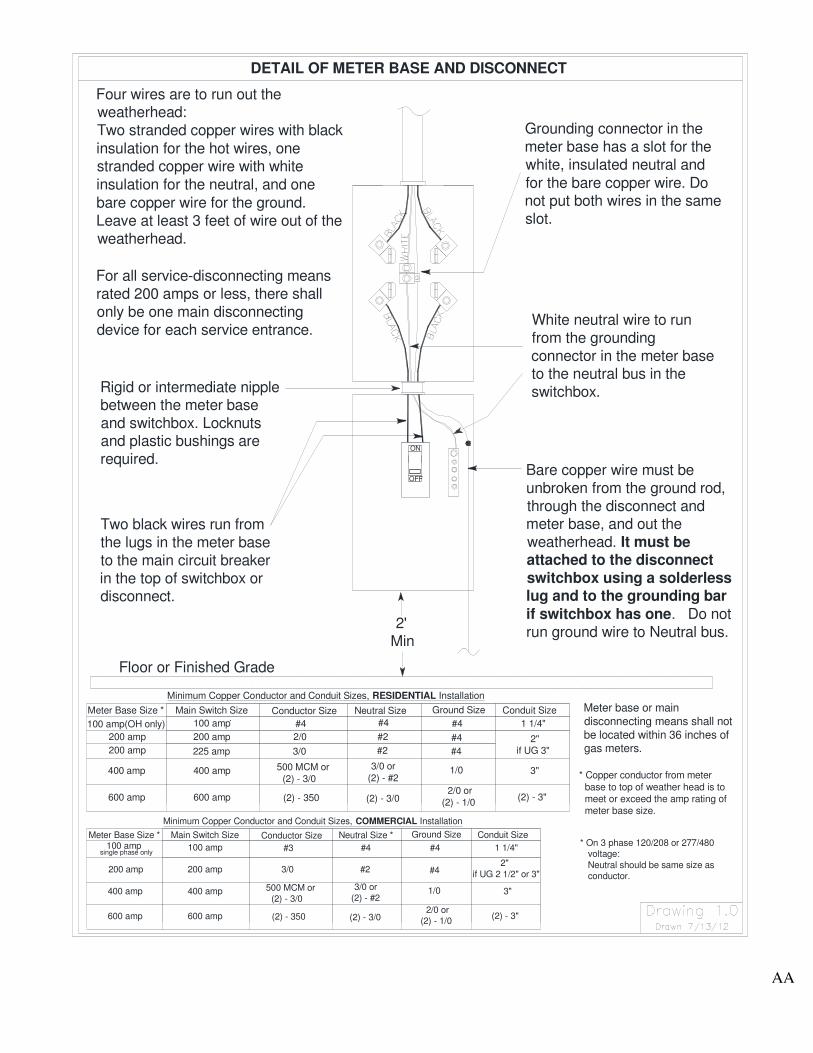
3.6 Detail of Meter Base and Disconnect
See Drawing 1.0 in Appendix A for Details of Typical Meter Base and
Disconnect.
3.7 Grounding
3.7.1 Grounding Conductor
There shall be a bare copper ground wire, of not less than no. 4-copper,
extending from the grounding electrode (ground rod) to the weatherhead (See
proper drawing in Appendix A for actual size of grounding conductor or
consult engineering department). Service entrances rated more than 200-
amp requires a larger grounding conductor. It may be installed inside or
outside the conduit, however where exposed it shall be fastened with
galvanized or other non-corrosive straps at intervals of not more than 12
inches. No more than four ground connections should be made to a single
driven electrode, each ground wire having a separate clamp. No splices shall
be allowed in the ground wire.
The meter base shall be bonded to the continuous ground. This may be done
by: 1) running the continuous ground through the ground lug in the center of
the meter base or 2) by connecting a piece of bare copper of the appropriate
size to the continuous grounding conductor using a split bolt and then
connecting to the ground lug in the meter base. The main disconnecting
means switch case shall be bonded by connecting a piece of the appropriate
size copper wire to the continuous ground using a split bolt and then
connecting to the switch case using a solderless lug. In addition, the
appropriate size copper wire must be attached to the grounding bar if the
switchbox or disconnect has one.
3.7.2 Grounding Electrode (Rod)
The grounding electrode shall be either: 1) ⅝-inch steel or iron rods, or 2) ½-
inch copper or approved non-ferrous rods. All of ground rods shall be driven to
a depth of 8 feet.
12
Section 4. Overhead Service
4.1 General Requirements
4.1.1 Point of Attachment and Location of Member’s Weatherhead
The point of attachment:
• SHALL BE DETERMINED BY ACE. ACE may require
relocation of the point of attachment and member’s weatherhead
on rewiring of old service installations. Information as to the
location of the point of attachment may be obtained by consulting the
Engineering Department and should be obtained before installation of
the point of attachment and the weatherhead.
• shall be provided by the member for the Association’s service drop to
the member’s premises and be suitable for attaching the service wires.
In cases where the point of attachment is in masonry, brick, block,
stucco, rock, metal, wood, etc., ACE may require the member to install
an assembly (such as an eye bolt) furnished by ACE for the attachment
of service conductors. In the event of low profile buildings, a mast-
type riser shall be required to provide the proper clearances. See
drawing 1.2 for residential or drawing 1.4 for commercial in Appendix
A for details on a mast-type riser.
• shall be of sufficient height to permit the Association’s service drop to
meet the requirements of the National Electric Safety Code, the
requirements of ACE shown in this installation guidebook, and any
other controlling ordinances or orders of authorities having
jurisdiction.
• shall not have any other attachments such as cable, internet, or
telephone.
• shall either be accessible to Association’s bucket truck or have proper
surface and sufficient ground space on member’s property to safely
support a ladder.
• shall have clear line of sight to the pole from which the service is or
will be attached.
• shall have a clearance of not less than 36 inches from windows, doors,
porches, fire escapes, or similar locations. In some cases, conductors
13
run above the top level of a window are considered out of reach from
that window. Please consult Engineering Department at ACE.
• shall be located within 36 inches of the weatherhead and shall be free
of any obstacles or angles that would interfere with connection
between the point of attachment and weatherhead unless otherwise
granted by special permission.
ACE shall make only one point of attachment of its service conductors to a
single building. If the point of attachment and location of weatherhead is
established without prior approval by ACE, then ACE reserves the right not to
make connection until any necessary relocation has been made to meet
ACE standards.
The point of attachment shall never be installed so the service drop would
extend over a temporary structure, permanent structure, or a swimming
pool.
4.1.2 Height of Attachment
The point of attachment and height of weatherhead shall be no less than:
12 feet - above finished grade, sidewalks, or from any platform or
projection from which they might be reached.
16 feet - above residential driveways and commercial areas such
as parking lots and drive-in establishments not subject to
truck traffic.
18 feet - above public streets, commercial areas, non-residential
drive ways, parking lots, agricultural areas, or other areas
subject to truck traffic.
In addition, the point of attachment shall be sufficient to maintain these same
clearances for the service conductors coming from ACE’s pole.
Consult the Engineering Department at ACE concerning all clearances.
The construction of a structure near, over, or under ACE’s power lines
may cause a code and/or safety violation.
4.2 Overhead Service Entrance Conductors
The service entrance conductors shall extend a minimum of 3 feet beyond the
weatherhead to provide space for proper attachment. It is preferable for the
14
conductors to have black insulation for hot wires and white for the neutral. Each
installation shall have copper service entrance conductors including the grounding
conductor. Aluminum conductor is not permitted.
The conductors shall be readily identifiable as to color, size, type, and insulation in
accordance with the National Electrical Code. Where the proper color conductors
are not readily available, painting or taping for identification is permissible.
Conductors shall be continuous without splices.
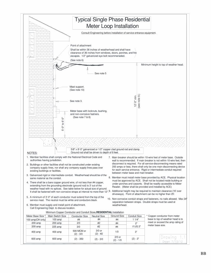
4.3 Residential Overhead Service Detail Requirements
4.3.1 Meter Loop Installations
See Drawing 1.1 in Appendix A
4.3.2 Service Mast Installations
See Drawing 1.2 in Appendix A
When the mast is extended more than 4 feet above the roof, it may be
necessary to install sufficient bracing to relieve the strain from the conduit.
Consult the ACE Engineering Department for proper bracing. Additionally,
no conduit couplings shall be installed above the roof line.
4.4 General Power (Commerical) Overhead Service Detail Requirements
4.4.1 Meter Loop Installations
See Drawing 1.3 in Appendix A
4.4.2 Service Mast Installations
See Drawing 1.4 in Appendix A
When the mast is extended more than 4 feet above the roof, it may be
necessary to install sufficient bracing to relieve the strain from the conduit.
Consult the ACE Engineering Department for proper bracing. Additionally,
no conduit couplings shall be installed above the roof line.
15
Section 5. Residential Underground Service Installations
5.1 General Residential Underground Requirements
A residence is defined as a single-family dwelling with a kitchen(s), bathroom(s),
and sleeping quarters. Apartments that are separately metered are covered under the
definition of residential installations.
ACE will, where practical, install underground services to new residential customers
desiring such service; provided the customer pays the difference in the cost of the
overhead versus underground (consult Engineering Department for costs) and meets
the following requirements:
• Member must provide and assemble, ready for mounting to pole, 3” rigid
or intermediate conduit of required length; together with weatherhead,
90 degree rigid sweep, female adapter, bonds, all straps, stand-off
brackets, grounding clamp, screws, etc., for attachment to ACE’s pole.
• Also, member will provide 3” schedule 40 PVC grey conduit the entire
distance from where member’s 90 degree rigid sweep is located on the
pole to the location where member installed conduit at the meter base.
• Member agrees to locate meter base, furnished by ACE, on house at point
determined by ACE and to install rigid, intermediate, or schedule 80 PVC
grey conduit as described in section 5.2 and shown in Drawing 1.6.
• Normally ACE will trench and install the 3” schedule 40 PVC grey
conduit provided by member from where customer’s rigid conduit 90
degree sweep is located on the pole to location where member installed
conduit at meter base provided that member pays appropriate fees to
ACE. In some cases, ACE may require member to install conduit. In these
cases, member shall provide and install the 3” schedule 40 PVC grey conduit.
The member shall install the conduit at a depth so that the distance from the
ground to the top of the conduit is a minimum of 24 inches. In some
circumstances the member may be required to install the conduit at a greater
depth as determined by ACE.
• In cases where the electric service is being provided from a pad mount
transformer, member will normally provide conduit and ACE will install
conduit from pad mount transformer to location where member installed
conduit at the meter base provided the member pays appropriate fees to ACE.
However, in some cases, ACE may require member to install conduit. The
member shall not dig within 3 feet of the pad mount. The member shall
contact Mississippi 811 by simply dialing 811 before digging and allow
all utilities time to locate their facilities. In these cases, member shall
provide and install the 3” schedule 40 PVC grey conduit.
16
• The member shall install the conduit at a depth so that the distance from the
ground to the top of the conduit is a minimum of 24 inches. However, the
member may be required to install the conduit at a greater depth by ACE.
5.2 General Underground Meter Base Requirements
The installation of an underground meter base shall conform to the requirements in
the General Guidelines under Section 3 of this guide (See Page 7) and also meet
the following requirements:
• The meter base shall be furnished by ACE and installed by the member. The
center of the meter socket shall be mounted between 5-feet and 6-feet above
finished grade, and shall be readily accessible.
• The meter base and conduit shall be mounted using non-corrosive straps and
fasteners. Rigid, intermediate, or Schedule 80 PVC conduit shall be used from
the ground to the meter base. Rigid or intermediate conduit shall be used
between the meter base and the main disconnecting means. No nails shall be used
to attach either the meter base or the conduit. Fasteners and straps shall be spaced
a maximum of 24 inches apart. The meter base shall be attached using a minimum
of four fasteners.
• The conduit for the underground service conductors entering the meter base shall
extend 24 inches below finished grade and shall contain no more than 90 degrees
of bend. In other words only one 90 degree sweep (one 90 degree bend) will be
allowed. The distance from the ground level to the top of the conduit shall be
a minimum of 24 inches. The conduit from the meter base extending to the
bottom of the ditch should lay flat against the building. Footings, etc. may require
forming or breaking in order to comply. Due to difficulties in pulling conductors,
the Association will require a minimum of 3” conduit for 200 and 400 amp
services. Two runs of 3” conduit will be required for 600 amp services.
• NOTE: Underground Service Installation is the ONLY instance where PVC
conduit is allowed under ACE’s standards. ACE allows Schedule 80 PVC to
be used from the ground to the meter base. However rigid or intermediate
conduit is required at the pole and between the meter base and the main
service disconnecting means.
• NO unauthorized persons are permitted to climb or work on ACE’s poles.
Arrangements shall be made to have ACE personnel present or to have
ACE’s permission when conduit is to be extended up the power pole. Please
contact ACE before you attach any conduit to ACE’s Pole.
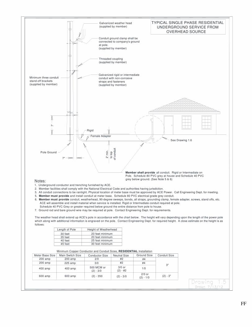
5.3 Underground Service Detail Requirements
See Drawing 1.5 and 1.6 in Appendix A
17
Section 6. General Power (Commercial) Underground Service
Installations
6.1 General Power (Commercial) Underground Service Requirements
A General Power Installation is any non-residence. This includes businesses,
churches, offices, warehouses, personal-use shops, and any other installation not
covered by the definition of a residence.
6.2 General Underground Meter Base Requirements
The installation of an underground meter base shall conform to the requirements in
the General Guidelines under Section 3 (See Page 7) and also meet the following
requirements. The meter base shall be furnished by ACE and installed by the
member. The center of the meter socket shall be mounted between 5-feet and 6-feet
above finished grade, and shall be readily accessible.
The meter base and conduit shall be mounted using non-corrosive straps and
fasteners. Rigid, intermediate, or Schedule 80 PVC conduit shall be used from the
ground to the meter base. Rigid or intermediate conduit shall be used between the
meter base and the main disconnect. No nails shall be used to attach either the meter
base or the conduit. Fasteners and straps shall be spaced a maximum of 24 inches
apart. The meter base shall be attached using a minimum of four fasteners.
The conduit for the underground service conductors entering the meter base shall
extend 24 inches below finished grade and shall contain no more than 90 degrees of
bend. In other words only one 90 degree sweep (one 90 degree bend) will be
allowed. The distance from the ground level to the top of the conduit shall be a
minimum of 24 inches. Footings, etc. may require forming or breaking in order to
comply.
NOTE: Underground Service Installation is the ONLY instance where PVC
conduit is allowed under ACE Power Association’s standards. ACE allows
Schedule 80 PVC to be used from the ground to the meter base. However rigid or
intermediate conduit is required at the pole. In addition rigid or intermediate
conduit is required between the meter base and the main service disconnecting
means.
NO unauthorized persons are permitted to climb or work on ACE’s poles.
Arrangements shall be made to have ACE personnel present or to have ACE’s
permission when conduit is to be extended up the power pole. Please contact
ACE before you attach any conduit to ACE’s Pole.
18
6.3 Underground Service from Overhead System General Requirements
The member shall provide, install, and own all secondary wire. ACE shall make the
connections at the transformer. Member shall install enough secondary wire so
that it can reach to transformer wire connectors near top of transformer. Please
consult engineering department for proper length to be run out of weatherhead.
The member shall provide, install, and own the conduit, straps, grounding bushing,
grounding clamps, stand-off brackets, etc. to be attached to ACE’s riser pole. ACE
shall normally assist in attaching the conduit to the riser pole. Rigid conduit will be
used on the pole including the elbow or “sweep L”. Schedule 80 PVC without
encasement or Schedule 40 PVC encased in concrete can be used underground.
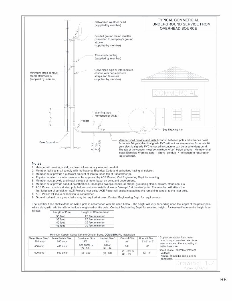
6.4 Underground Service from Overhead System Detail Requirements
See Drawing 1.7 and Drawing 1.8 in Appendix A.
6.5 Underground Service from Underground System General Requirements
(normally pad-mounted transformer)
When the member requests a pad-mounted transformer and underground service the
member shall pay the necessary cost and the following requirements shall be met:
• ACE should be informed as early as possible as to the member’s load, voltage
requirements, ampacity of the service entrance, and the size of the secondary
wire (copper only) for the service entrance so that the necessary transformer,
connectors, etc. can be ordered if they are not in stock.
• The member shall pour a concrete pad for the three phase transformer that
shall be a minimum of 12 inches thick. Drawings 1.10 and Drawing 1.11
shows the details. Contact ACE Engineering Department to determine
which drawing to use. The pad is to be a minimum of 5 feet from the
building (if building surface is non-combustible) and positioned so that the
doors open away from the building to provide working clearance. If building
surface is combustible then pad must be a greater distance from the
building. Please contact ACE for exact distance. For single phase
transformers ACE will provide the concrete pad in most cases. However,
ACE may require the member to pour a concrete pad for a single phase
transformer. The member shall provide 2 ground rods, one in the primary
side of the cabinet and one in the secondary side of the cabinet. If the
transformer is to be located in an area that is accessible to vehicles the
member shall install barriers around the transformer.
19
• The member shall provide, install, and own all secondary wire and conduit.
ACE shall make the connections at the transformer.
• The member shall provide, install, and own the conduit from the transformer
to ACE’s riser pole, including the conduit, standoff brackets, straps,
grounding bushing, etc. to be attached to ACE Power’s pole, and provide a
pull rope. ACE Power shall assist in attaching the conduit to the riser pole. A
minimum of 4” rigid conduit shall be required on the riser pole. The “Sweep
L” at both the riser pole and transformer pad shall also be rigid conduit,
minimum of 48” radius. A minimum of 4” schedule 40 PVC encased in
concrete or schedule 80 PVC without encasement shall be used underground
and shall be installed at a depth of 48 inches from the ground level to the top
of the conduit. A spare run of conduit is recommended but not required.
However, at such time as the conduit must be replaced or repaired, the
customer shall be responsible for providing a replacement.
• ACE Power shall provide, install, and own the transformer and the primary
cable. This shall include terminating the wire at the transformer and at the
riser pole.
6.6 Underground Service from Underground System Detail Requirements
(normally pad-mounted transformer)
See Drawing 1.9 in Appendix A. In addition, see drawings 1.10 and 1.11 for three phase
transformer concrete pad specifications in Appendix A. Contact ACE Engineering
Department to determine which drawing the member should follow. ACE will normally
provide the concrete pad for single phase transformers.

20
Section 7. Mobile Homes and Temporary Services
7.1 General Comments
Meter bases shall be provided by ACE for mobile home and temporary
services. In most cases, a fee may be charged to the member for meter bases on
temporary poles.
All mobile homes shall have the service equipment located adjacent to the
mobile home on a Mobile Home Service Pole and not mounted on or in the
mobile home. All mobile homes and temporary services shall have a main
disconnecting means located on the service pole. The main disconnecting means
shall have a minimum rating of 100 amps. For all service disconnecting means rated
200 amps or less, there shall only be one main disconnecting device for each service
entrance.
All temporary service poles shall be constructed in the same manner as Mobile Home
Service Poles. All 120 volt circuits shall be protected by ground fault interrupters.
All fittings shall be galvanized or non-corrosive and the switch shall be rain tight and
approved for outdoor use. Boxes, shields, or coverings will not be acceptable for
making switches rain tight.
If upon notification by member, ACE makes a trip to render service and the
member’s service pole is found unacceptable for connection, the member may be
billed for such trip and each unnecessary trip thereafter.
ACE will rent and install a temporary service pole if the member so desires in some
cases. Temporary service poles used at the same location for longer than six months
must have special permission from ACE.
7.2 Service Pole Requirements
The Mobile Home Service Pole shall be a treated, wooden timber of minimum size 6
inches by 6 inches square timber or have a diameter of not less than 6 inches (21 inch
circumference) at the ground line for a round pole. The minimum length shall be 20
feet, 16 feet extending out of the ground and shall be buried 4 feet deep, provided
other clearance requirements are met. However, ACE may require a taller pole in
some circumstances. Please consult the ACE Engineering Department before
beginning project. In addition, call Mississippi 811 before you dig.
7.3 Mobile Home or Temporary Service General Requirements
In addition to the other regulations in this guide, member shall install a minimum ½”
galvanized eye bolt with a 2” x 2” washer. The eye bolt shall be installed 8-12” from
the top of the pole.
21
Rigid or intermediate conduit shall be used above the meter base. The conduit
shall be secured by using non-corrosive straps with a maximum separation of 24”
between the straps. A minimum of four conduit straps shall be used. In addition,
rigid or intermediate conduit shall be used between the meter base and the main
service disconnecting means located on the pole. Locknuts and plastic bushings are
required. Rigid, intermediate, PVC Grey conduit, or water tight flex with metal
inside conduit walls may be used from the main service disconnecting means to the
switch box.
The conduit shall be secured by means of galvanized or non-corrosive straps spaced
every 2 feet under the chassis of the trailer when the meter pole is located no more
than 1 foot from the surface of the trailer. The conductor shall be run underground
in an approved fashion in conduit when the meter pole is greater than 1 foot from the
trailer.
All fittings shall be galvanized or non-corrosive and the main service disconnecting
means shall be rain tight and approved for outdoor use. Boxes, shields, or coverings
shall not be acceptable for making switches rain tight.
Galvanized rigid or intermediate weatherheads shall be used. The service entrance
conductors shall extend at least 3 feet out of the weatherhead. All service entrance
conductors must be copper. No Aluminum conductors will be accepted.
Grounding of both electrical and non-electrical metal parts in a mobile home is
through connection to a grounding bus in the mobile home distribution panel. The
grounding bus is grounded by running the appropriate size copper wire from the
mobile home distribution panel to the ground connection in the main disconnecting
means, located adjacent to the mobile home. Neither the frame of the mobile home
nor the frame of any appliance may be connected to the neutral conductor in the
mobile home.
7.4 Mobile Home or Temporary Service Detail
The service equipment for the Service Pole shall consist of the appropriate size
conductors, conduit, meter base, and main service disconnect. Details are on
Drawing 1.12 for Mobile homes and Drawing 1.13 for Temporary Services.
7.5 Signs, Billboards, etc.
Signs, billboards, CATV amplifier installations, etc. shall conform to the
standards listed in the General Guidelines in addition to this section.
22
Section 8. Multiple Meter Installations (Gang Meter Bases)
8.1 General Comments
All gang meter bases must be furnished and installed by the member and must
conform to the regulations given in the General Guidelines in Section 3 of this
guidebook in addition to the following requirements. All gang meter bases shall
have an Underwriters Laboratories (UL) Label and each meter socket in the gang
meter base shall have a barrel lock with guard provision (BLG). All gang meter
bases must be approved by ACE before the gang meter base is installed. ACE
reserves the right to deny service to any location with a gang meter base that does not
meet ACE’s requirements.
Meters must be protected from physical damage. Gang meter bases shall not be
mounted on a pole.
All gang meter bases used for General Power (commercial) installations shall
have a manual bypass lever for each meter. This will normally allow ACE to
change out meters without interrupting service to the member.
All gang meter bases shall have a main service disconnecting means with appropriate
size circuit breaker assembly or fuse receptacle located adjacent to each meter.
8.2 Labeling of Meters
Details are on Drawing 1.14. Labeling must be installed before ACE will connect
the gang meter installation or any location that has multiple meter bases.
8.3 Multiple Meter Installation Detail
Details are on Drawing 1.14.
23
Section 9. Three Phase Service
9.1 General Comments
When three phase service is requested by an applicant whose load could
satisfactorily be serviced by single phase service, and three phase service is not
readily available, three phase service may be provided at the discretion of ACE based
on the following provision. The applicant will make an advance payment in aid of
construction to ACE. This payment will be equal to the difference in cost of
providing single phase service and the cost of providing three phase service. This
payment will be credited against the cost of construction. No credit will be allowed
on the applicant’s electric bills, nor will any refund be made in the event of
termination of service.
9.2 Details for Three Phase Service
In addition to the other regulations in this guide, members will follow Section 4 for
Overhead Three Phase service and Section 6 for Underground Three Phase Service.
However, on 120/208 and 277/480 volt services, the member will be required to
provide the same size neutral as the phase conductors. If member decides to
use larger conductor than required for phase or neutral conductor, then
contact ACE before installation. Conductors can be too large for meter base
lugs.

24
Section 10. Motor Loads
10.1 Single Phase Motors
1. Motors of five horsepower and smaller may be started across the line, provided,
such starting does not cause undue interference to other consumers served from
the same transformer. On equipment containing two or more motors exceeding
five horsepower in total, the controls should be connected or operated so that
motors will not be started simultaneously.
2. Motors in excess of five horsepower normally should have current limiting
devices, such as: resistance starters, capacitor start, capacitor start-capacitor run
characteristics or equivalent.
3. Any motor whose starting characteristics are such as to limit the starting current
to 300 percent of full load current will be acceptable, regardless of type of
starting device used, for single phase motors of 10 horsepower and smaller.
4. Normally, single phase motors larger than 10 horsepower will be considered as
a special application and will be served only when the user meets the
requirements set forth by ACE for this application.
10.2 Three Phase Motors
1. 15 horsepower and smaller motors operated singly can be started across the line.
On equipment containing two or more motors exceeding 15 horsepower in total,
the controls should be connected or operated so that motors will not be started
simultaneously.
2. Motors larger than 15 horsepower, up to and including 75 horsepower, must be
equipped with starting devices so as to limit the starting current to 300 percent
of full load current.
3. Motors in excess of 75 horsepower must be equipped with starting devices
so as to limit the starting current to 250 percent of full load current.
4. Motors in excess of 150 horsepower shall be considered a special application
and will be served only when the user meets the requirements set forth by ACE
for this application.
In certain instances, special circumstances may require that further limitations
be enforced by ACE.
25
Section 11. Member Owned Generators
11.1 Generators Interconnected and Operated in Parallel with the Electric
Utility Grid
Contact the Engineering Department of ACE before beginning installation of any backup
generator that will be connected before the main switch box.
Backup Generators shall be permitted to interconnect and operate in parallel with ACE’s
distribution system provided that all of the following conditions are met throughout the
life of the interconnection:
1. The quality and reliability of service to any of ACE’s members shall not be
diminished or affected as a result of the interconnection.
2. The safety of the public and ACE’s employees or equipment shall not be reduced
or affected in any way as a result of the interconnection.
3. The generator is connected through a double pole, double throw transfer switch
that has a visibly open break that can be verified by ACE’s employees. The
members shall supply a disconnect method acceptable to ACE. The disconnect
and transfer switch shall normally be located on the outside of the facility and
accessible to ACE personnel at all times.
See Drawing 1.15 in Appendix A.

APPENDIX A
Detail Drawings of Member Installation Requirements For Electric Service
AA
3/0
#3
Conductor Size
(2) - 350
500 MCM or
(2) - 3/0
Minimum Copper Conductor and Conduit Sizes, COMMERCIAL Installation
Conductor Size
(2) - 350
500 MCM or
(2) - 3/0
Minimum Copper Conductor and Conduit Sizes, RESIDENTIAL Installation
For all service-disconnecting means
rated 200 amps or less, there shall
only be one main disconnecting
device for each service entrance.
DETAIL OF METER BASE AND DISCONNECT
Four wires are to run out theweatherhead:
Two stranded copper wires with black
insulation for the hot wires, onestranded copper wire with white
insulation for the neutral, and one
bare copper wire for the ground.
Leave at least 3 feet of wire out of the
weatherhead.
400 amp 400 amp
single phase only
600 amp
400 amp
200 amp
Meter Base Size *
600 amp
100 amp
600 amp
200 amp
100 amp
Main Switch Size
400 amp
600 amp
200 amp
100 amp(OH only)
200 amp
Meter Base Size *
Floor or Finished Grade
Two black wires run from
the lugs in the meter base
to the main circuit breaker
in the top of switchbox ordisconnect.
200 amp
225 amp
100 amp
Main Switch Size
Rigid or intermediate nipplebetween the meter base
and switchbox. Locknutsand plastic bushings are
required.Bare copper wire must be
unbroken from the ground rod,
through the disconnect andmeter base, and out the
weatherhead. It must beattached to the disconnect
switchbox using a solderlesslug and to the grounding bar
if switchbox has one. Do not
run ground wire to Neutral bus.
3" 3/0 or
(2) - #21/0
#4
#4
Ground Size
2/0 or
(2) - 1/0
1/0 3/0 or
(2) - #2
(2) - 3/0
Neutral Size *
#2
#4
(2) - 3/0
(2) - 3"
2"
if UG 2 1/2" or 3"
1 1/4"
Conduit Size
3"
2/0 or
(2) - 1/0(2) - 3"
2'Min
Neutral Size
2/0
#4
3/0
#2
#4
#2
Conduit SizeGround Size
#4
#4
#4
2"
if UG 3"
1 1/4"
* Copper conductor from meter
base to top of weather head is to
meet or exceed the amp rating of
meter base size.
* On 3 phase 120/208 or 277/480 voltage:
Neutral should be same size as conductor.
Meter base or main
disconnecting means shall not
be located within 36 inches ofgas meters.
White neutral wire to run
from the grounding
connector in the meter baseto the neutral bus in the
switchbox.
Grounding connector in the
meter base has a slot for the
white, insulated neutral and
for the bare copper wire. Donot put both wires in the same
slot.
OFF
ON
BB
5/8" x 8'-0" galvanized or 1/2" copper clad ground rod and clamp.
Ground rod shall be driven to depth of 8 feet.
#4
#4
#4
Ground Size
2/0 or
(2) - 1/0
1/0
Minimum Copper Conductor and Conduit Sizes, RESIDENTIAL Installation
7. Main breaker should be within 10-wire feet of meter base. Outside
wall is recommended. If main breaker is not within 10-wire feet, then
disconnect is required. For all service-disconnecting means rated
200 amps or less, there shall only be one main disconnecting device
for each service entrance. Rigid or intermediate conduit required
between meter base and main breaker.
8. Member must install meter base provided by ACE. Physical location
must be approved by ACE. Shall not be located inside building or
under porches and carports. Shall be readily accessible to Meter
Reader. (Meter shall be provided and installed by ACE)
9. Additional height may be required to maintain clearance (16' over
driveways). Point of attachment can be no higher than 25'.
10. Non-corrosive conduit straps and fasteners, no nails allowed. Max 24"
separation between straps. Double straps must be used at
weatherhead.
400 amp 3/0 or
(2) - #2500 MCM or (2) - 3/0
400 amp
600 amp600 amp (2) - 350 (2) - 3/0
200 amp
225 amp
100 amp
Main Switch Size
1. Member facilities shall comply with the National Electrical Code and
authorities having jurisdiction.
2. Buildings or other facilities shall not be constructed under existing
company supply lines, nor shall any company supply lines pass over
existing buildings or facilities.
3. Galvanized rigid or intermediate conduit. Weatherhead should be of the
same material as the conduit.
4. There shall be a bare copper ground wire, of not less than #4 copper,
extending from the grounding electrode (ground rod) to 3' out of the
weather head with no splices. See table below for actual size of ground.
It shall be fastened with non-corrosive straps at interval no more than 12".
5. A minimum of 3'-0" of each conductor must extend from the top of the
service mast. The neutral must be white and conductors black.
6. Member must supply and install point of attachment.
Call Engineering Dept. to discuss location.
200 amp
100 amp(OH only)
200 amp
Meter Base Size *
NOTES:
Conductor Size
2/0
#4
3/0
Neutral Size
#2
#4
#2
3"
(2) - 3"
* Copper conductor from meter
base to top of weather head is to
meet or exceed the amp rating of
meter base size. 2"
if UG 3"
Conduit Size
1 1/4"
Typical Single Phase Residential Meter Loop Installation
Shall be within 36 inches of weatherhead and shall have
clearance of 36 inches from windows, doors, porches, and fire
escapes. 1/2" galvanized eye bolt recommeneded.
Consult Engineering before installation of service entrance equipment.
Meter base with locknuts, bushing,
and non-corrosive fastners.
(See note 7 & 8)
5'-0"
to 6
'-0"
Mast support.
(See note 10)
See note 3.
See note 5
Point of attachment
(See note 6)
Minimum height to top of weather head.
12
'-0"
min
.
(se
e n
ote
9.)

CC
Conductor Size
500 MCM or
(2) - 3/0
Minimum Copper Conductor and Conduit Sizes, RESIDENTIAL Installation
Typical Single Phase Residential Service Mast Installation
5. A minimum of 3'-0" of each conductor must extend from the top of the service mast. The neutral must be white and conductors black.
4. Galvanized rigid weatherhead and conduit, minimum 2" inside diameter.
No coupling allowed above the roofline.
3. Buildings or other facilities shall not be constructed under existing
company supply lines, nor shall any company supply lines pass over
existing buildings or facilities.
1. Member facilities shall comply with the National Electrical Code and
authorities having jurisdiction.
2. Distance from facia to center of mast to be 4'-0" max. NEC 230-24
6. Main breaker should be within 10-wire feet of meter base. Outside
wall is recommended. If main breaker is not within 10-wire feet, then
disconnect is required. For all service-disconnecting means rated
200 amps or less, there shall only be one main disconnecting device
for each service entrance. Rigid or intermediate conduit required
between meter base and main breaker.
5/8" x 8'-0" galvanized or 1/2" copper clad ground rod and clamp.
Ground rod shall be driven to depth of 8 feet.
600 amp
400 amp
200 amp
100 amp(OH only)
200 amp
Meter Base Size *
200 amp
225 amp
100 amp
Main Switch Size
600 amp
400 amp
#4
(2) - 350
3/0
2/0
NOTES:
MA
X.
25'-0"
12
'-0
" m
in.
(Se
e n
ote
9)
Consult Engineering Dept. before
installing service entrance equipment.
Minimum mounting height
for point of attachment
7. Non-corrosive conduit straps and fasteners, no nails allowed. Max 24"
separation between straps.
* Copper conductor from meter
base to top of weather head is to
meet or exceed the amp rating of
meter base size.
11. There shall be a bare copper ground wire, of not less than #4 copper,
extending from the grounding electrode (ground rod) to 3' out of the
weather head with no splices. See table below for actual size of ground.
It shall be fastened with non-corrosive straps at interval no more than
12".
9. Additional height may be required to maintain clearance (16' over
driveways). Point of attachment can be no higher than 25'.
8. Member must install meter base provided by ACE. Physical location
must be approved by ACE. Shall not be located inside building or
under porches and carports. Shall be readily accessible to Meter
Reader. (Meter shall be provided and installed by ACE)
10. No telephone or cable attachment allowed on mast. NEC 230-28
(2) - 3/0
Conduit Size
12. Guy is required if 5' above roof line.
#4
3/0 or(2) - #2
#2
#2
Neutral Size
#4
#4
#4
2/0 or(2) - 1/0
1/0
Ground Size
1 1/4"
3"
(2) - 3"
2"if UG 3"
5'-0
" to
6'-0"
Meter base with locknuts,
bushing, and non-corrosive
fastners. (See note 6 & 8)
4'-0" MAX.
(See note 2)
(See note 4, 10 and 12)
(Se
e n
ote
12)
4' m
in.
(See note 5)
Point of attachment
(See note 9)

DD
Meter Loop Installation
* On 3 phase 120/208 or 277/480
voltage: Neutral should be same size as
conductor.
* Copper conductor from meter
base to top of weather head is to
meet or exceed the amp rating of
meter base size.
Consult engineering before installation of service entrance equipment.
Minimum height to top of weather head.
10. Non-corrosive conduit straps and fasteners, no nails allowed. Max 24"
separation between straps. Double straps must be used at weatherhead.
9. Additional height may be required to maintain clearance (18' over
driveways). Point of attachment can be no higher than 25'.
8. Member must install meter base provided by ACE. Physical location
must be approved by ACE. Shall not be located inside building or
under porches and carports. Shall be readily accessible to Meter
Reader. (Meter shall be provided and installed by ACE)
7. Main breaker should be within 10-wire feet of meter base. Outside
wall is recommended. If main breaker is not within 10-wire feet, then disconnect is required. For all service-disconnecting means rated
200 amps or less, there shall only be one main disconnecting device
for each service entrance. Rigid or intermediate conduit required between meter base and main breaker.
5/8" x 8'-0" galvanized or 1/2" copper clad ground rod and clamp.
Ground rod shall be driven to depth of 8 feet.
Minimum Copper Conductor and Conduit Sizes, COMMERCIAL Installation
5. A minimum of 3'-0" of each conductor must extend from the top of the service mast. The neutral must be white and conductors black.
4. There shall be a bare copper ground wire, of not less than #4 copper,
extending from the grounding electrode (ground rod) to 3' out of
the weather head with no splices. See table below for actual size of
ground. It shall be fastened with non-corrosive straps at interval no more than 12".
3. Galvanized rigid or intermediate conduit. Weatherhead should be of the same material as the conduit.
2. Buildings or other facilities shall not be constructed under existing
company supply lines, nor shall any company supply lines pass over
existing buildings or facilities.
1. Member facilities shall comply with the National Electrical Code and
authorities having jurisdiction.
6. Member must supply and install point of attachment.
Call Engineering Dept to discuss location.
400 amp 400 amp
600 amp 600 amp
single phase only
Meter Base Size *
100 amp
200 amp 200 amp
100 amp
Main Switch Size
NOTES:
3" 3/0 or
(2) - #21/0500 MCM or
(2) - 3/0
2/0 or
(2) - 1/0(2) - 350 (2) - 3/0 (2) - 3"
Ground Size
3/0
#3
Conductor Size Neutral Size *
#4
#2
Conduit Size
#4
#4
1 1/4"
2"
5'-0"
to 6
'-0"
Meter base with locknuts, bushing,
and non-corrosive fastners.
(See note 7 & 8)
Mast support.
(See note 10)
See note 3.
See note 5
(se
e n
ote
9.)
12'-0
" m
in.
Typical Commercial
Shall be within 36-inches of weatherhead and shall have
clearance of 36-inches from windows, doors, porches, and fire
escapes. 1/2" galvanized eye bolt recommeneded.
Point of attachment
(See note 6)

EE
* On 3 phase 120/208 or 277/480
voltage: Neutral should be same size as conductor.
* Copper conductor from meter
base to top of weather head is to
meet or exceed the amp rating of meter base size.
Point of attachment
(See note 9)
10. No telephone or cable attachment allowed on mast. NEC 230-28
8. Member must install meter base provided by ACE. Physical location
must be approved by ACE. Shall not be located inside building or
under porches and carports. Shall be readily accessible to Meter
Reader. (Meter shall be provided and installed by ACE)
9. Additional height may be required to maintain clearance (18' over
driveways). Point of attachment can be no higher than 25'.
7. Non-corrosive conduit straps and fasteners, no nails allowed. Max 24"
separation between straps.
11. There shall be a bare copper ground wire, of not less than #4 copper,
extending from the grounding electrode (ground rod) to 3' out of the
weather head with no splices. See table below for actual size of ground.
It shall be fastened with non-corrosive straps at interval no more than
12".
1. Member facilities shall comply with the National Electrical Code and
authorities having jurisdiction.
Main Switch Size
Minimum Copper Conductor and Conduit Sizes, COMMERCIAL Installation
6. Main breaker should be within 10-wire feet of meter base. Outside
wall is recommended. If main breaker is not within 10-wire feet, then
disconnect is required. For all service-disconnecting means rated
200 amps or less, there shall only be one main disconnecting device
for each service entrance. Rigid or intermediate conduit required
between meter base and main breaker.
2. Distance from facia to center of mast to be 4'-0" max. NEC 230-24
3. Buildings or other facilities shall not be constructed under existing
company supply lines, nor shall any company supply lines pass over
existing buildings or facilities.
4. Galvanized rigid weatherhead and conduit, minimum 2" inside diameter.
No coupling allowed above the roofline.
5. A minimum of 3'-0" of each conductor must extend from the top of the service mast. The neutral must be white and conductors black.
single phase only
100 amp
200 amp
Meter Base Size *
400 amp
600 amp
100 amp
200 amp
600 amp
400 amp
Ground Size
2/0 or
(2) - 1/0
12. Guy is required if 5' above roof line.
3/0
(2) - 350
500 MCM or
(2) - 3/0
#3
Conductor Size
(2) - 3/0
3/0 or
(2) - #2
#2
#4
Neutral Size *
1 1/4"
Conduit Size
(2) - 3"
#4
1/0
#4
3"
2"
Typical Commercial Service Mast Installation
Consult Engineering Dept. beforeinstalling service entrance equipment.
5/8" x 8'-0" galvanized or 1/2" copper clad ground rod and clamp.
Ground rod shall be driven to depth of 8 feet.NOTES:
Minimum mounting height
for point of attachment
4'-0" MAX.
(See note 2)
Meter base with locknuts,
bushing, and non-corrosive
fastners. (See note 6 & 8)
MA
X. 25'-0"
12'-0"
min
. (S
ee n
ote
9)
5'-0"
to 6
'-0"
(See note 4, 10 and 12)
(See
note
12)
4' m
in.
(See note 5)
FF
Notes:1. Underground conductor and trenching furnished by ACE.
2. Member facilities shall comply with the National Electrical Code and authorities having jurisdiction.
3. All conduit connections to be raintight. Physical location of meter base must be approved by ACE Power. Call Engineering Dept. for meeting.
5. Member must provide and install conduit at meter base. Schedule 80 PVC electrical grade grey conduit.
6. Member must provide conduit, weatherhead, 90-degree sweeps, bonds, all straps, grounding clamp, female adapter, screws, stand offs, etc.
ACE will assemble and install material when service is installed. Rigid or Intermediate conduit required at pole.
Schedule 40 PVC Grey or greater required below ground the entire distance from pole to house.
7. Ground rod and bare ground wire may be required at pole. Contact Engineering Dept. for requirements.
The weather head shall extend up ACE's pole in accordance with the chart below. The height will vary depending upon the length of the power pole
which along with additional information is engraved on the pole. Contact Engineering Dept. for required height. A close estimate on the height is as
follows:
Length of Pole
30 feet
35 feet
40 feet
45 feet
Pole Ground
7"
Member shall provide all conduit. Rigid or Intermediate on
Pole. Schedule 80 PVC grey at house and Schedule 40 PVC
grey below ground. (See Note 5 & 6)
Height of Weatherhead
20 feet minimum
20 feet minimum
25 feet minimum
30 feet minimum
2' m
in.
to
to
p
of con
du
it
7'
Minimum three conduit
stand-off brackets
(supplied by member)
See Drawing 1.6
Galvanized rigid or intermediate
conduit with non-corrosive
straps and fasteners
(supplied by member)
Threaded coupling
(supplied by member)
TYPICAL SINGLE PHASE RESIDENTIAL
UNDERGROUND SERVICE FROM
OVERHEAD SOURCE
Galvanized weather head
(supplied by member)
Neutral Size
Minimum Copper Conductor and Conduit Sizes, RESIDENTIAL Installation
400 amp 500 MCM or
(2) - 3/0
600 amp (2) - 350
Main Switch Size
225 amp
200 amp
Conductor Size
2/0
3/0
1/0 3/0 or(2) - #2
3"
(2) - 3/0 2/0 or
(2) - 1/0(2) - 3"
Conduit SizeGround Size
#2
#2
#4
#4
Meter Base Size
200 amp
200 amp
400 amp
600 amp
Rigid
Conduit ground clamp shall be
connected to company's ground
at pole.
(supplied by member)
Female Adapter

GG
Upper end of ground rod
to be flush with or below
ground level. Ground rod
driven to depth of 8 feet.
Notes:1. Member facilities shall comply with the National Electrical Code and authorities having jurisdiction.
2. All conduit connections to be rain tight.
3. Physical location of meter base must be approved by ACE Power. Call Engineering Dept. for meeting.
4. Member must provide and install conduit including sweep at meter base.
5. Main breaker shall be within 10-wire feet of meter. Outside wall is recommended. If main breaker is not within 10-wire feet, then disconnect is
required. Rigid or intermediate conduit required between meter base and main breaker.
6. If PVC, Schedule 80 grey electrical grade conduit is required.
7. If PVC, Schedule 40 or 80 grey electrical grade conduit is required. (90 degree 24" radius required)
TYPICAL SINGLE PHASE RESIDENTIAL UNDERGROUND
METER INSTALLATION
To top of conduit.
200 amp
225 amp
Main Switch Size
600 amp
400 amp
Minimum Copper Conductor and Conduit Sizes, RESIDENTIAL Installation
400 amp
600 amp
200 amp
200 amp
Meter Base Size
3" 3/0 or
(2) - #21/0500 MCM or
(2) - 3/0
(2) - 3/0(2) - 350 2/0 or
(2) - 1/0(2) - 3"
Neutral Size
3/0
2/0
Conductor Size
#2
#2
Ground Size
#4
#4
Conduit Size
Conduit, elbow attachments,
and bushings to be furnished
and installed by member
(See note 6.)
2
'
min
.
5'-0
" to
6'-0"
24" radius min.
factory bend
(See note 7.)
Meter base provided by ACE.
(See note 3, 4 & 5.)
5/8" x 8'-0" galvanized or
1/2" copper clad ground rod
and clamp.
HH
TYPICAL COMMERCIAL
UNDERGROUND SERVICE FROM
OVERHEAD SOURCE
Galvanized weather head
(supplied by member)
Conduit ground clamp shall beconnected to company's ground
at pole.(supplied by member)
Threaded coupling
(supplied by member)
Galvanized rigid or intermediate
conduit with non-corrosivestraps and fasteners
(supplied by member)
Minimum three conduit
stand-off brackets
(supplied by member)
Warning tape
Furnished by ACE
Rigid
7'
See Drawing 1.812"
Pole Ground
7" 2' m
in.
to
top
of
co
ndu
it Member shall provide and install conduit between pole and entrance point.
Schedule 80 grey electrical grade PVC without encasement or Schedule 40
grey electrical grade PVC encased in concrete can be used underground.The top of the conduit must be minimum of 24" below ground. Member shall
install Electrical Warning tape 1' above conduit. 4" of concrete required on
top of conduit.
Notes:1. Member will provide, install, and own all secondary wire and conduit.
2. Member facilities shall comply with the National Electrical Code and authorities having jurisdiction.
3. Member must provide a sufficient amount of wire to reach top of transformer(s).
4. Physical location of meter base must be approved by ACE Power. Call Engineering Dept. for meeting.
5. Member must provide and install conduit at meter base, on pole, and underground.
6. Member must provide conduit, weatherhead, 90 degree sweeps, bonds, all straps, grounding clamp, screws, stand offs, etc.
7. ACE Power must install riser pole before customer installs elbow or "sweep L" at the riser pole. The member will attach the
first full piece of conduit on ACE Power's riser pole. ACE Power will assist in attaching the remaining conduit to the riser pole.
8. ACE Power will make connection to transformer.
9. Ground rod and bare ground wire may be required at pole. Contact Engineering Dept. for requirements.
The weather head shall extend up ACE's pole in accordance with the chart below. The height will vary depending upon the length of the power pole
which along with additional information is engraved on the pole. Contact Engineering Dept. for required height. A close estimate on the height is as
follows:Length of Pole Height of Weatherhead
30 feet
35 feet40 feet
45 feet
20 feet minimum20 feet minimum
25 feet minimum
30 feet minimum
Neutral Size *
Minimum Copper Conductor and Conduit Sizes, COMMERCIAL Installation
400 amp 500 MCM or (2) - 3/0
600 amp (2) - 350
Main Switch Size
200 amp
Conductor Size
3/0
1/0 3/0 or(2) - #2
3"
(2) - 3/0 (1) - 2/0 or
(2) - 1/0(2) - 3"
Conduit SizeGround Size
#2 #4 2 1/2" or 3"
Meter Base Size *
200 amp
400 amp
600 amp
* Copper conductor from meter
base to top of weather head is to
meet or exceed the amp rating of
meter base size.
* On 3 phase 120/208 or 277/480 voltage:
Neutral should be same size as
conductor.
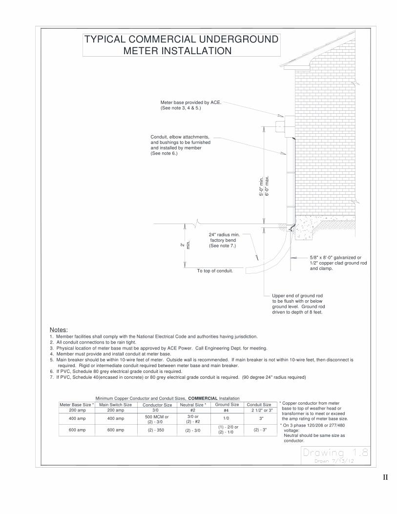
II
* On 3 phase 120/208 or 277/480 voltage: Neutral should be same size as
conductor.
* Copper conductor from meter
base to top of weather head or
transformer is to meet or exceed the amp rating of meter base size.
Notes:1. Member facilities shall comply with the National Electrical Code and authorities having jurisdiction.
2. All conduit connections to be rain tight.
3. Physical location of meter base must be approved by ACE Power. Call Engineering Dept. for meeting.
4. Member must provide and install conduit at meter base.
5. Main breaker should be within 10-wire feet of meter. Outside wall is recommended. If main breaker is not within 10-wire feet, then disconnect is
required. Rigid or intermediate conduit required between meter base and main breaker.
6. If PVC, Schedule 80 grey electrical grade conduit is required.
7. If PVC, Schedule 40(encased in concrete) or 80 grey electrical grade conduit is required. (90 degree 24" radius required)
Upper end of ground rod
to be flush with or below
ground level. Ground rod
driven to depth of 8 feet.
To top of conduit.
200 amp
Main Switch Size
600 amp
400 amp
Minimum Copper Conductor and Conduit Sizes, COMMERCIAL Installation
400 amp
600 amp
200 amp
Meter Base Size *
3" 3/0 or
(2) - #21/0500 MCM or
(2) - 3/0
(2) - 350 (2) - 3/0 (1) - 2/0 or
(2) - 1/0(2) - 3"
Conductor Size
3/0
Neutral Size *
#2 2 1/2" or 3"
Conduit SizeGround Size
#4
TYPICAL COMMERCIAL UNDERGROUND
METER INSTALLATION
24" radius min.
factory bend
(See note 7.)
Conduit, elbow attachments,
and bushings to be furnished
and installed by member
(See note 6.)
2'
min
.
5'-0"
min
.
6'-0
" m
ax.
Meter base provided by ACE.
(See note 3, 4 & 5.)
5/8" x 8'-0" galvanized or
1/2" copper clad ground rod
and clamp.

JJ
2 1/2" or 3"
TYPICAL COMMERCIAL 3 PHASE
UNDERGROUND SERVICE FROM
OVERHEAD SOURCE
Member shall provide and install conduit between pole and transformer pad.
Schedule 80 grey electrical grade PVC without encasement or Schedule 40
grey electrical grade PVC encased in concrete can be used underground.
The top of the conduit must be minimum of 48" below ground. 4" of concrete
required on top of schedule 40 conduit.
Notes:1. Member will provide, install, and own all secondary wire and conduit.
2. Member facilities shall comply with the National Electrical Code and authorities having jurisdiction.
3. Member must provide and install secondary wire from main or meter base to a minimum of 6' out of conduit at concrete pad.
4. Physical location of meter base must be approved by ACE Power. Call Engineering Dept. for meeting.
5. Member must provide and install conduit at meter base, on pole, and underground.
6. Member must provide (4") conduit, weatherhead, 90 degree sweeps, bonds, all straps, grounding bushing, screws, stand offs, etc.
7. ACE Power must install riser pole before member installs elbow or "sweep L" at the riser pole. The customer will attach the
first full piece of conduit on ACE Power's riser pole. ACE Power will assist in attaching the remaining conduit to the riser pole.
8. ACE Power will provide, install, and own the transformer and the primary cable. This will include terminating the wire at the
transformer and at the riser pole.
The conduit shall extend up ACE's pole in accordance with the chart below. The height will vary depending upon the length of the power pole which
along with additional information is engraved on the pole. Contact Engineering Dept. for required height. A close estimate on the height is as
follows:
7"
4
' min
. t
o top
of cond
uit
Meter Base Size *
Length of Pole
30 feet
35 feet
40 feet
45 feet
600 amp
400 amp
200 amp
Minimum Copper Conductor and Conduit Sizes, COMMERCIAL Installation
Neutral Size *
600 amp
200 amp
Main Switch Size
400 amp
(2) - 350
500 MCM or
(2) - 3/0
Conductor Size
3/0 #4
Ground Size
(1) - 2/0 or
(2) - 1/0
1/0
(2) - 3/0
#2
3/0 or
(2) - #2
(2) - 3"
Conduit Size
3"
Height of Weatherhead
20 feet minimum
20 feet minimum25 feet minimum
30 feet minimum
Minimum three conduit
stand-off brackets
(supplied by member)
7'
Pole Ground
Galvanized rigid or intermediate
(4") conduit with non-corrosive
straps and fasteners
(supplied by member)
Rigid(48" radius)
Ground bushing shall beconnected to company's groundat pole.
(supplied by member)
Threaded coupling
(supplied by member)
* On 3 phase 120/208 or 277/480
voltage: Neutral should be same size as
conductor.
* Copper conductor from meter
base to transformer is to meet
or exceed the amp rating of
meter base size.
Schedule 80 grey electrical grade PVC
without encasement or Schedule 40grey electrical grade PVC encased inconcrete can be used underground.
The top of the conduit must be minimum
of 24" below ground. 4" of concrete
required on top of schedule 40 conduit.
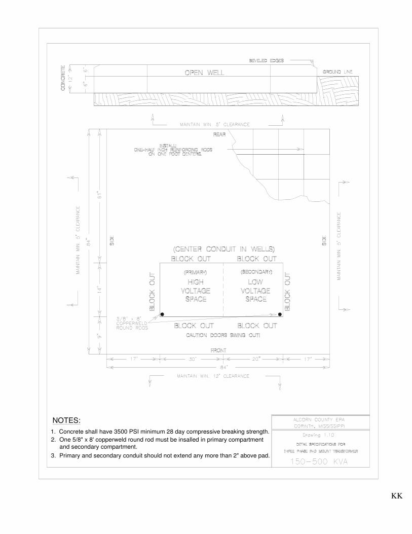
KK
1. Concrete shall have 3500 PSI minimum 28 day compressive breaking strength.
2. One 5/8" x 8' copperweld round rod must be insalled in primary compartment
and secondary compartment.
3. Primary and secondary conduit should not extend any more than 2" above pad.
NOTES:
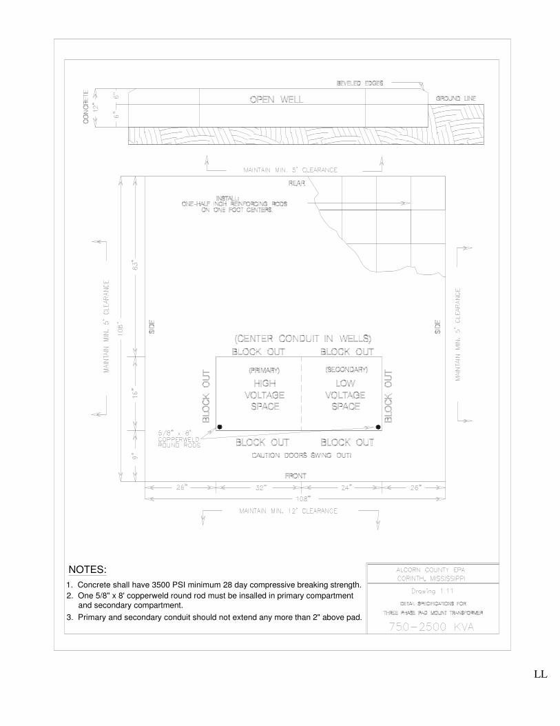
LL
3. Primary and secondary conduit should not extend any more than 2" above pad.
2. One 5/8" x 8' copperweld round rod must be insalled in primary compartment and secondary compartment.
1. Concrete shall have 3500 PSI minimum 28 day compressive breaking strength.
NOTES:

MM
4' m
in.
NOTES:1. Member facilities shall comply with National Electrical Code and
authorities having jurisdiction.
2. All conduit connections to be raintight.
3. Physical location of pole and any guying (if needed) will be approved
by ACE Power. Call Engineering Dept. for meeting.
4. No utility service lines will be installed over any structures.
5. Member installed minimum 1/2" galvanized eye bolt with 2"x2" square
washer recommended.
6. There shall be a bare copper ground wire, of not less than #4 bare
copper, extending from the grounding electrode (ground rod) to 3' out of
the weather head with no splices. See actual size ground below.
7. Taller pole may be required when power line crosses road or drive way.
Call Engineering Dept. to discuss.
200 amp
225 amp
100 amp
Main Switch Size
600 amp
400 amp
Minimum Copper Conductor and Conduit Sizes, RESIDENTIAL Installation
Call Before You Dig (811)The Member shall notify One Call and shall have One Call locate all underground
facilities before digging. It shall be the responsibility of the Member to stay clear of
all underground facilities.
100 amp(OH only)
200 amp
400 amp
600 amp
200 amp
Meter Base Size * * Copper conductor from meter
base to top of weather head is to
meet or exceed the amp rating of
meter base size.
1 1/4"
#4
#4
#2
#4
2/0
#4
2/0 or
(2) - 1/0
500 MCM or
(2) - 3/0
(2) - 350
3/0
3/0 or
(2) - #2
(2) - 3/0
#2
3"1/0
(2) - 3"
#4 2"
Ground SizeConductor Size Neutral Size Conduit Size
14
' min
.
TYPICAL SINGLE PHASE SERVICE POLE INSTALLATION
20' m
in (
See n
ote
7)
15
' min
.
16
' min
.
Minimum size treated pole (or equivalent), 6" diameter (21" circumference at
ground line) or 6"x6" square.
Non-corrosive straps, minimum of four conduit straps. Maximum 24"
separation between straps. No nails allowed.
Meter base with locknuts, bushings, and non-corrosive fasteners(Meter base
Provided by ACE). No nails allowed. All single phase installations shall be
3-wire, 120/240 volts.
Galvanized rigid or intermediate nipple between meter base and disconnect.
Disconnect with overcurrent protection to be enclosed in weatherproof box.
The switch shall have a minimum rating of 100 amps. For all
service-disconnecting means rated 200 amps or less, there shall only be one
main disconnecting device for each service entrance.
8' ground rod 1/2" copper or 5/8" galvanized with approved ground rod
clamp. Upper end of ground rod to be with or below grade. Ground rod
driven to depth of 8 feet.
5' t
o 6
'
2' m
in.
Galvanized rigid or intermediate conduit.
Service Entrance Conductors
Hot Wires-Black, Neutral-White, Grounding Conductor #4 Bare Copper
Minimum. Extend wires at least 3 feet out of weatherhead. Galvanized rigid
or intermediate weatherhead shall be used. (See actual size of ground
below)
Eye bolt to be located 8-12" from top of pole.
See note 5

NN
NOTES:1. Member facilities shall comply with National Electrical Code and
authorities having jurisdiction.
2. All conduit connections to be raintight.
3. Physical location of pole and any guying (if needed) will be approved
by ACE Power. Call Engineering Dept. for meeting.
4. No utility service lines will be installed over any structures.
5. Member installed minimum 1/2" galvanized eye bolt with 2"x2" square
washer recommended.
6. There shall be a bare copper ground wire, of not less than #4 bare
copper, extending from the grounding electrode (ground rod) to 3' out of
the weather head with no splices. See actual size ground below.
7. Taller pole may be required when power line crosses road or drive way.
Call Engineering Dept. to discuss.
4' m
in.
Ground Size
Minimum Copper Conductor and Conduit Sizes, COMMERCIAL Installation
The Member shall notify One Call and shall have One Call locate all underground
facilities before digging. It shall be the responsibility of the Member to stay clear of
all underground facilities.
Main Switch Size
Call Before You Dig (811)
100 amp100 ampsingle phase only
600 amp
400 amp
200 amp
400 amp
600 amp
200 amp
Meter Base Size *
#4#4#3
3/0
(2) - 350
500 MCM or
(2) - 3/0
3/0 or
(2) - #2
(2) - 3/0
#2
1/0
2/0 or
(2) - 1/0
#4
Neutral Size *Conductor Size
* On 3 phase 120/208 or 277/480
voltage: Neutral should be same size as conductor.
* Copper conductor from meter
base to top of weather head is to
meet or exceed the amp rating of meter base size.
1 1/4"
(2) - 3"
3"
2"
Conduit Size
TYPICAL TEMPORARY SERVICE POLE INSTALLATION
Eye bolt to be located 8-12" from top of pole.
Service Entrance Conductors
Hot Wires-Black, Neutral-White, Grounding Conductor #4 Bare Copper
Minimum. Extend wires at least 3 feet out of weatherhead. Galvanized rigid
or intermediate weatherhead shall be used. (See actual size of ground
below)
Minimum size treated pole (or equivalent), 6" diameter (21" circumference at
ground line) or 6"x6" square.
Non-corrosive straps, minimum of four conduit straps. Maximum 24"
separation between straps. No nails allowed.
Galvanized rigid or intermediate conduit.
Meter base with locknuts, bushings, and non-corrosive fasteners(Meter base
Provided by ACE). No nails allowed. All single phase installations shall be
3-wire, 120/240 volts.
Galvanized rigid or intermediate nipple between meter base and disconnect.
Disconnect with overcurrent protection to be enclosed in weatherproof box.
The switch shall have a minimum rating of 100 amps. For allservice-disconnecting means rated 200 amps or less, there shall only be one
main disconnecting device for each service entrance.
8' ground rod 1/2" copper or 5/8" galvanized with approved ground rod
clamp. Upper end of ground rod to be with or below grade. Ground rod
driven to depth of 8 feet.
20' m
in (
See
note
7)
16
' min
.
14' m
in.
15
' min
.
2' m
in.
5' t
o 6
'
See note 5

OO
Minimum Copper Conductor and Conduit Sizes, COMMERCIAL Installation
Notes: 1. Labels must be brass or other rust-resistant metal.
2. Identification numbers and letters must be stamped, and must be one-inch in height.
3. Labels must be fastened to the meter center with two rivets. Gluing is not acceptable.
4. Labels must be placed on the front panel adjacent to the meter serving that apartment number, or business, or
street address(See Figure above).
5. Owners or management companies are responsible for ACE time spent correcting crossed meters
due to incorrectly marked bases.
6. A main disconnect is required for seven or more disconnects.
7. All self-contained nonresidential meter sockets (except temporary services) require a manual
lever bypass. Call Engineering Dept. for approval of gang meter base.
8. Member to obtain meter location from ACE Power.
9. Schedule 80 PVC electrical grade grey conduit or rigid conduit may be used.
10. Gang meter base shall have an UL label and each meter socket shall have a barrel lock with guard
provision(BLG).
7'Max
MULTIPLE METER INSTALLATIONS (Gang Meter)
Service Entrance
(See Note 9)
200 amp
Main Switch Size
600 amp
400 amp
Main Disconnect
(See Note 6)
(See Notes 1-5)
Neutral Size
(2) - 3/0
3/0 or
(2) - #2
Floor or Finished Grade
(2) - 350
500 MCM or
(2) - 3/0
Conductor Size
3/0
Ground Size
#2
(1) - 2/0 or
(2) - 1/0
#4
1/0
2' Min
3'
Min
7-1/2"
Min
8-1/2" Min
5' Min
6' Preferred 7' Max
2 1/2" or 3"
Conduit Size
(2) - 3"
3"
(See Note 9)
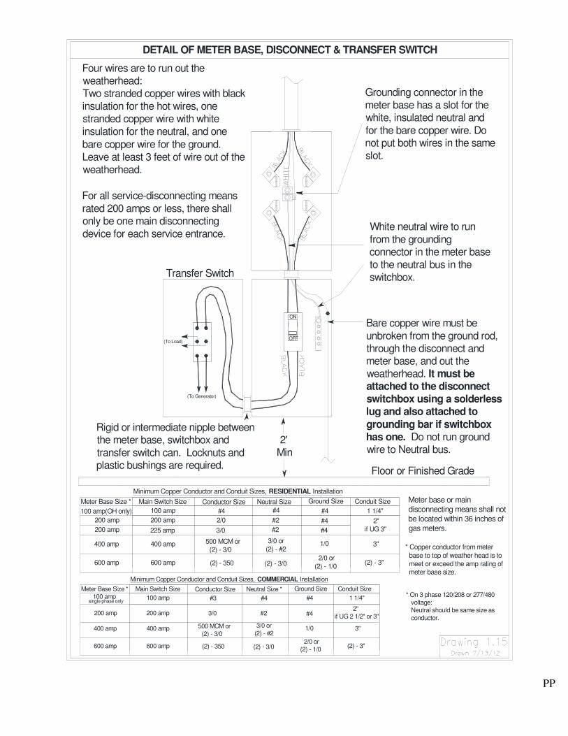
PP
Conductor Size
(2) - 350
500 MCM or
(2) - 3/0
Minimum Copper Conductor and Conduit Sizes, COMMERCIAL Installation
Conductor Size
500 MCM or
(2) - 3/0
Minimum Copper Conductor and Conduit Sizes, RESIDENTIAL Installation
Rigid or intermediate nipple betweenthe meter base, switchbox and
transfer switch can. Locknuts andplastic bushings are required.
Transfer Switch
(To Generator)
For all service-disconnecting means
rated 200 amps or less, there shallonly be one main disconnecting
device for each service entrance.
DETAIL OF METER BASE, DISCONNECT & TRANSFER SWITCH
Four wires are to run out theweatherhead:Two stranded copper wires with black
insulation for the hot wires, onestranded copper wire with white
insulation for the neutral, and one
bare copper wire for the ground.
Leave at least 3 feet of wire out of theweatherhead.
400 amp 400 amp
single phase only
600 amp
400 amp
100 amp
200 amp
Meter Base Size *
600 amp
600 amp
200 amp
100 amp
Main Switch Size
400 amp
600 amp
200 amp
100 amp(OH only)
200 amp
Meter Base Size *
200 amp
225 amp
100 amp
Main Switch Size
(To Load)
Bare copper wire must be
unbroken from the ground rod,through the disconnect andmeter base, and out theweatherhead. It must beattached to the disconnectswitchbox using a solderlesslug and also attached to
grounding bar if switchboxhas one. Do not run groundwire to Neutral bus.
Floor or Finished Grade
3" 3/0 or
(2) - #21/0
Ground Size
2/0 or
(2) - 1/0
3/0 or
(2) - #2
(2) - 3/0
Neutral Size *
3/0
#3
(2) - 350
#2
#4
(2) - 3/0
(2) - 3"
2"
if UG 2 1/2" or 3"
1 1/4"
Conduit Size
#4
1/0
#4
2/0 or
(2) - 1/0
3"
(2) - 3"
2'Min
2/0
#4
3/0
#4
Neutral Size
#2
#2 #4
#4
#4
Ground Size
2"
if UG 3"
1 1/4"
Conduit Size
* Copper conductor from meter
base to top of weather head is to
meet or exceed the amp rating of meter base size.
* On 3 phase 120/208 or 277/480 voltage: Neutral should be same size as
conductor.
Meter base or main
disconnecting means shall not
be located within 36 inches of
gas meters.
White neutral wire to run
from the groundingconnector in the meter baseto the neutral bus in the
switchbox.
Grounding connector in the
meter base has a slot for thewhite, insulated neutral and
for the bare copper wire. Donot put both wires in the sameslot.
OFF
ON

APPENDIX B
Major Changes from Previous Wiring Guide
1. Page 7, Section 3.1 - No self-contained meter bases shall be installed on an ACE owned Pole.
2. Page 9, Section 3.4.1 - One main, service disconnecting means (main) shall be provided to
disconnect all energized load-side conductors from the service-entrance
conductors for entrances rated 200 amperes or less.
3. Page 11, Section 3.7.1- Services entrances rated more than 200 amperes required a larger
grounding conductor. (See proper drawing in Appendix A for actual
size of grounding conductor.
4. Page 15, Section 5.1 - Member shall provide 3” schedule 40 PVC grey conduit or greater for all
residential services to be installed below ground by ACE. Rigid or
Intermediate conduit is still required at the pole and must be provided by the
member. A minimum of Schedule 80 PVC grey conduit is still required
at the house above ground and must be provided and installed by the
member. Rigid or intermediate conduit required between meter base
and main disconnecting means. Also see Drawing 1.5 on page FF and
Drawing 1.6 on page GG.
5. Page 22, Section 8.1 All gang meter bases shall have an Underwriters Laboratories (UL) Label and
each meter socket in the gang meter base shall have a barrel lock with guard
provision (BLG). All gang meter bases used for General Power (Commercial)
Members shall have a manual bypass lever for each meter. This will normally
allow ACE to change out meters without interrupting service to the member.
6. Page 25, Section 11 This whole section is new to the wiring guide.

RR