Embed Size (px)
Citation preview
P R E P A R E D B Y
T X R E G . # F - 1 5 9 4
D E C E M B E R 2 0 2 1
E L E C T R I C S E R V I C E S T A N D A R D
E L E C T R I C S E R V I C E S T A N D A R D │ D E C E M B E R 1 4 , 2 0 2 1
D E N T O N M U N I C I P A L E L E C T R I C │ 2
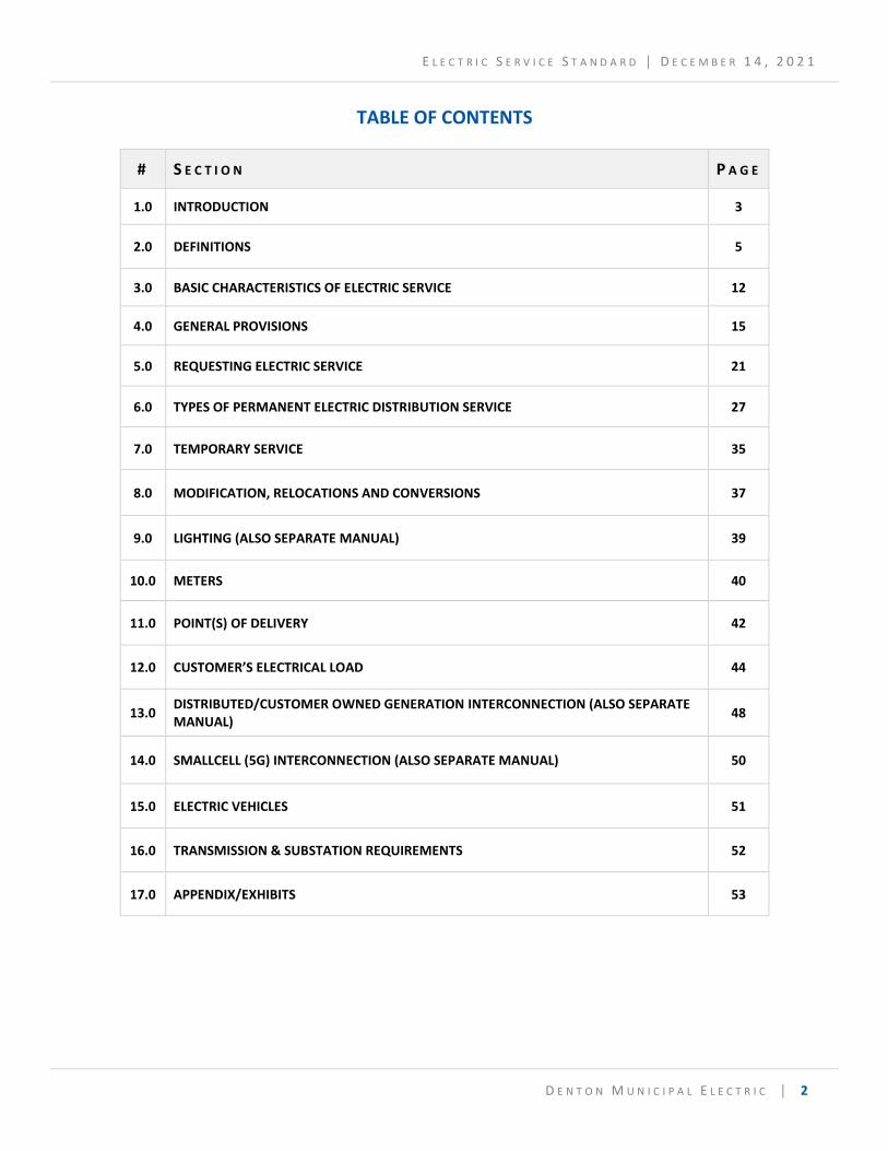
TABLE OF CONTENTS
# S E C T I O N P A G E
1.0 INTRODUCTION 3
2.0 DEFINITIONS 5
3.0 BASIC CHARACTERISTICS OF ELECTRIC SERVICE 12
4.0 GENERAL PROVISIONS 15
5.0 REQUESTING ELECTRIC SERVICE 21
6.0 TYPES OF PERMANENT ELECTRIC DISTRIBUTION SERVICE 27
7.0 TEMPORARY SERVICE 35
8.0 MODIFICATION, RELOCATIONS AND CONVERSIONS 37
9.0 LIGHTING (ALSO SEPARATE MANUAL) 39
10.0 METERS 40
11.0 POINT(S) OF DELIVERY 42
12.0 CUSTOMER’S ELECTRICAL LOAD 44
13.0 DISTRIBUTED/CUSTOMER OWNED GENERATION INTERCONNECTION (ALSO SEPARATE MANUAL)
48
14.0 SMALLCELL (5G) INTERCONNECTION (ALSO SEPARATE MANUAL) 50
15.0 ELECTRIC VEHICLES 51
16.0 TRANSMISSION & SUBSTATION REQUIREMENTS 52
17.0 APPENDIX/EXHIBITS 53
E L E C T R I C S E R V I C E S T A N D A R D │ D E C E M B E R 1 4 , 2 0 2 1
D E N T O N M U N I C I P A L E L E C T R I C │ 3
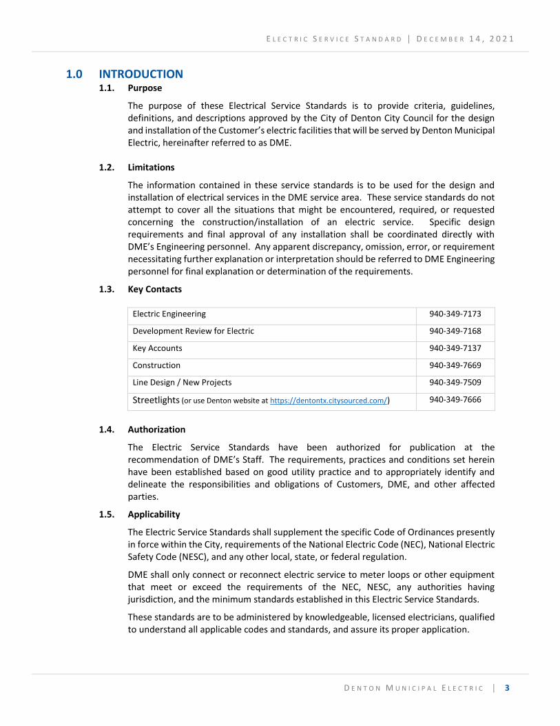
1.0 INTRODUCTION
1.1. Purpose
The purpose of these Electrical Service Standards is to provide criteria, guidelines, definitions, and descriptions approved by the City of Denton City Council for the design and installation of the Customer’s electric facilities that will be served by Denton Municipal Electric, hereinafter referred to as DME.
1.2. Limitations
The information contained in these service standards is to be used for the design and installation of electrical services in the DME service area. These service standards do not attempt to cover all the situations that might be encountered, required, or requested concerning the construction/installation of an electric service. Specific design requirements and final approval of any installation shall be coordinated directly with DME’s Engineering personnel. Any apparent discrepancy, omission, error, or requirement necessitating further explanation or interpretation should be referred to DME Engineering personnel for final explanation or determination of the requirements.
1.3. Key Contacts
Electric Engineering 940-349-7173
Development Review for Electric 940-349-7168
Key Accounts 940-349-7137
Construction 940-349-7669
Line Design / New Projects 940-349-7509
Streetlights (or use Denton website at https://dentontx.citysourced.com/) 940-349-7666
1.4. Authorization
The Electric Service Standards have been authorized for publication at the recommendation of DME’s Staff. The requirements, practices and conditions set herein have been established based on good utility practice and to appropriately identify and delineate the responsibilities and obligations of Customers, DME, and other affected parties.
1.5. Applicability
The Electric Service Standards shall supplement the specific Code of Ordinances presently in force within the City, requirements of the National Electric Code (NEC), National Electric Safety Code (NESC), and any other local, state, or federal regulation.
DME shall only connect or reconnect electric service to meter loops or other equipment that meet or exceed the requirements of the NEC, NESC, any authorities having jurisdiction, and the minimum standards established in this Electric Service Standards.
These standards are to be administered by knowledgeable, licensed electricians, qualified to understand all applicable codes and standards, and assure its proper application.
E L E C T R I C S E R V I C E S T A N D A R D │ D E C E M B E R 1 4 , 2 0 2 1
D E N T O N M U N I C I P A L E L E C T R I C │ 4
Responsibility to ensure compliance with all codes and standards remains with the customer.
DME shall not be deemed to have assumed any responsibility with respect to any such action herein authorized or taken by DME, with respect to proper construction or compliance with any code or standard.
1.6. Revisions Process
The Distribution Standards Committee of DME controls the issue and distribution of the Electric Service Standards and the updates to this document. Any request for revision from any user of the manual are to be initiated by a written proposal forwarded to the Standards Committee. Each request will be evaluated.
E L E C T R I C S E R V I C E S T A N D A R D │ D E C E M B E R 1 4 , 2 0 2 1
D E N T O N M U N I C I P A L E L E C T R I C │ 5
2.0 DEFINITIONS / GLOSSARY
2.1 Accessible (as applied to wiring methods):
Capable of being removed or exposed without damaging the building structure or finish, or not permanently closed in by the structure or finish of the building. (Applicable Reference – NEC 100)
2.2 Accessible (as applied to equipment):
Admitting close approach; not guarded by locked doors, elevation, or other effective means. (Applicable Reference – NEC 100)
2.3 Accessible, Easily (as applied to distributed generation):
Capable of being quickly approached for testing, service, inspections, disconnects, or connects, regardless of fence location. Doors, gates, or other barriers must be unlocked, unless DME personnel are furnished with convenient means to bypass the barrier for full and safe access to equipment.
2.4 Accessible, Readily:
Capable of being reached quickly for operation, renewal, or inspections, without requiring those to whom ready access is requisite to climb over or remove obstacles or to resort to portable ladders, chairs, and so forth. (Applicable Reference – NEC 100 Section 2)
2.5 Accessory Dwelling Unit:
A subordinate dwelling unit added to, created within, or detached from a single-family residence, that contains a dwelling that is subordinate to a principal single-family detached dwelling and that provides basic requirements for living, sleeping, cooking, and sanitation. A HUD-Code manufactured home shall not be considered an accessory dwelling unit.
2.6 Aid-in-Construction:
A fee required to offset the cost of construction of facilities outside those normally allowed for installation of electric service.
2.7 Approved:
Acceptable to Denton Municipal Electric (DME) or other Authority having jurisdiction. (Applicable Reference – NEC 100)
2.8 Authority:
Any person or organization with the legal right to control or regulate the devices or actions under discussion.
2.9 Building:
"Building" referred to in these standards includes all occupancies within the same outside walls under a common roof. Individual occupancies separated by firewalls or fire barriers do not constitute separate buildings for the purpose of receiving electric service drops or laterals.
E L E C T R I C S E R V I C E S T A N D A R D │ D E C E M B E R 1 4 , 2 0 2 1
D E N T O N M U N I C I P A L E L E C T R I C │ 6
2.10 Cabinet:
An enclosure that is designed for either surface mounting or flush mounting and is provided with a frame, mat, or trim in which a swinging door or doors, or can be hung. (Applicable Reference – NEC 100)
2.11 Cable:
A solid conductor with insulation, or a stranded conductor with or without insulation and other coverings (single-conductor cable), or a combination of conductors insulated from one another (multiple-conductor cable). (Applicable Reference – NESC Section 2)
2.12 Certification Area:
See “Service Area” below.
2.13 Conductors Considered Outside of Building:
Conductors shall be considered outside of a building or other structure if they are installed under any of the following conditions (Applicable Reference – NEC 230.6):
2.13.1 Where installed under not less than two-inches of concrete beneath a building or other structure; or
2.13.2 Where installed within a building or other structure in a raceway that is encased in concrete or brick not less than two inches thick; or
2.13.3 Where installed in any vault that meets the construction requirements of NEC Article 450, Part III; or
2.13.4 Where installed in conduit under not less than twenty-four (24”) inches of earth beneath a building or other structure.
2.14 Conductor, Electric:
A material usually in the form of a wire, cable, or bus bar, suitable for carrying an electric current. (Applicable Reference – NESC Section 2)
2.15 Conduit:
A single channel designed and approved specifically for electrical conductors.
2.16 Customer:
Any individual, partnership, association, joint venture, firm, public or private corporation or governmental agency who is applicant for, or who is receiving the benefit of electric service at a specified Point of Delivery from DME. This term also includes any authorized representative who designs or constructs the service and meter installation.
2.17 Customer’s Installation:
With the exception of DME meter installation, all wiring, devices, apparatus and appliances of any kind or nature useful in connection with Customer’s ability to take electric service that are installed on Customer's side of the DME determined Point of Delivery.
2.18 Demand:
Demand is a measure of electrical power magnitude, not total energy usage. The term "demand" as used herein shall mean the maximum electrical load during any specified time
E L E C T R I C S E R V I C E S T A N D A R D │ D E C E M B E R 1 4 , 2 0 2 1
D E N T O N M U N I C I P A L E L E C T R I C │ 7
interval, sometimes also referred to as “peak demand.” The anticipated maximum demand for new or additional services will be determined by appropriate DME personnel and will be used to determine the size and rating of all equipment used in the DME service installation. Demand may be expressed in terms of amperes, watts, or volt-amperes.
Demand is used in two contexts in these service standards; 1) metering demand which is the power used by the Customer averaged over a time interval and 2) electrical demand which is the actual power flowing through the distribution facilities. These values will be determined by DME Engineering for the purposes of sizing DME owned service equipment and may differ significantly from the Customer’s undiversified total connected load which is the sum total of manufacturer’s name plate/equipment watt or ampere ratings for all of the Customer’s electrical load.
2.19 Denton Municipal Electric (DME):
The municipal electric utility owned and operated by the City of Denton, Texas.
2.20 Disconnecting Means:
A device, or group of devices, or other means by which the conductors of a circuit can be disconnected from their means of supply. (Applicable Reference – NEC 100)
2.21 Dwelling, One-Family:
A building that consists solely of one dwelling unit. (Applicable Reference – NEC 100)
2.22 Dwelling, Two-Family:
A building that consists solely of two dwelling units. (Applicable Reference – NEC 100)
2.23 Dwelling, Multi-Family:
One or more buildings on a single lot containing five or more dwelling units. This definition includes single room occupancy, co-housing, and residential condominiums developed on a single lot. This definition does not include duplex, triplex, fourplex, or tiny home development.
2.24 Dwelling Unit:
A single unit, providing complete and independent living facilities for one or more persons, including permanent provisions for living, sleeping, cooking, and sanitation. (Applicable Reference – NEC 100)
2.25 Enclosure:
The case or housing of apparatus, or the fence or wall that surrounds an installation to prevent personnel from accidentally contacting energized parts, or to protect the equipment from physical damage. (Applicable Reference – NEC 100)
2.26 Enclosure, Meter:
An enclosure whose purpose is housing the DME kWh or kW meter(s). (See 2.34 and 2.35 herein)
2.27 Enclosure, Instrument Transformer:
An enclosure whose purpose is housing the DME instrument transformers (voltage or current transformers).
E L E C T R I C S E R V I C E S T A N D A R D │ D E C E M B E R 1 4 , 2 0 2 1
D E N T O N M U N I C I P A L E L E C T R I C │ 8
2.28 Energy, Electric:
Electrical power (kilowatts) consumed over a given amount of time. The unit of energy as used herein shall be the kilowatt-hour. (a Kilowatt-hour is 1000 watt-hours).
2.29 Garage:
A building or portion of a building in which one or more self-propelled vehicles can be kept for use, sale, storage, rental, repair, exhibition, or demonstration purposes. (Applicable Reference – NEC 100)
2.30 Ground:
A conducting connection, whether intentional or accidental, between an electrical circuit or equipment and the earth, or to some conducting body that serves in place of the earth. (Applicable Reference – NEC 100)
2.31 Grounded:
Connected to the earth or to some conducting body that serves in place of the earth. (Applicable Reference – NEC 100)
2.32 Grounded Effectively:
Intentionally connected to the earth through a ground connection or connections of sufficiently low impedance and having sufficient current-carrying capacity to prevent the buildup of voltages that may result in undue hazards to connected equipment or to persons.
2.33 Meter:
The device or any auxiliary equipment installed by DME to measure customer electric energy and demand. Meters are classified as either single-phase or three-phase and are either self-contained or transformer-rated. Self-contained meters operate directly from the service voltage and load current. Transformer-rated meters require current transformers (“CT's”) or voltage transformers (“VT's”), or both, to reduce the service current or voltage when they are beyond the measuring capacity of self-contained meters.
2.34 Meter Loop:
All wiring and connections within the meter or instrument transformer enclosure or meter socket required to connect metering equipment to a Customer's residence or place of business. This equipment usually consists of service lateral or service entrance conductors within the meter or instrument transformer enclosure or meter socket for connection to the line and load side of metering equipment.
2.35 Meter Base:
A DME-approved enclosure of weather resistant design used for mounting a detachable type self-contained meter. (See Appendix C)
2.36 National Electrical Code (NEC, ANSI/NFPA-70):
An American National Standard published by the National Fire Protection Association for the purposes of safeguarding persons and property from hazards arising from the use of electricity and setting forth provisions considered necessary for safety. Electrical contractors must abide by the NEC for internal and external wiring of buildings and
E L E C T R I C S E R V I C E S T A N D A R D │ D E C E M B E R 1 4 , 2 0 2 1
D E N T O N M U N I C I P A L E L E C T R I C │ 9
structures. This National Electric Code shall be referred to herein as the NEC and it shall be the latest edition. Some NEC data referred to herein may be modified from time to time as determined by the National Fire Protection Association or its successors. The more stringent requirements shall apply where there is a difference between DME service standards and the NEC.
2.37 National Electrical Safety Code (NESC, ANSI C2):
An American National Standard published by the Institute of Electrical and Electronics Engineers, Inc. (IEEE).
The most current revision of the National Electric Safety Code shall be referred to herein as the NESC. Some NESC data referred to herein may be modified from time to time as determined by the IEEE or its successor(s). The more stringent requirements shall apply where there is a difference between DME service standards and the NESC.
2.38 Permanent Electric Service
Electric service that is installed for use at Customer site and will be used continuously for at least 2 years.
2.39 Point of Delivery:
The point where the electric energy first leaves the conductors or devices owned by DME and enters the service entrance, other conductors, or devices owned by customer. See also “Service Point” below.
2.40 Property Owner:
The owner of the real property where electric structures, equipment, or easements are located.
2.41 Raceway:
An enclosed channel of metal or nonmetallic materials designed expressly for holding wires, cables or buss-bars, with additional functions as permitted by NEC 100. "Raceway" as used herein will mean one or more above ground conduits.
2.42 Service area
DME is authorized to provide electric service to customers within the city limits and some nearby areas outside of the city limits. Regardless of authorization to serve customers within the service area, service may or may not be readily available depending on factors such as existing distribution facilities, overhead vs. underground service, number of phases, voltages and configurations (Wye vs. Delta), etc.
The Certification Map (see Appendix A) shows the areas within DME’s service area that are Single, Double, or Triple Certified. Single Certified means that only one service provider (DME) is authorized to provide electric service to the area. Double Certified means that two providers (DME and another company) are authorized to compete for and provide electric service to the area, and so on.
2.43 Service Conductors:
The conductors from the Point of Delivery to the service disconnecting means. (Applicable Reference – NEC 100)
E L E C T R I C S E R V I C E S T A N D A R D │ D E C E M B E R 1 4 , 2 0 2 1
D E N T O N M U N I C I P A L E L E C T R I C │ 1 0
2.44 Service Drop:
The overhead service conductors extending from the DME overhead distribution system to the Point of Delivery where the connection is made to the Customer’s service-entrance conductors at the building. (Applicable Reference – NEC 100)
2.45 Service-entrance Conductors – Overhead System:
The service conductors between the terminals of the service equipment and a point usually outside the building, clear of building walls, where joined by taps or splice, to the service drop. (Applicable Reference – NEC 100)
2.46 Service-entrance Conductors – Underground System:
The conductors between the terminals of the service equipment and the point of connection to the service lateral. (Applicable Reference – NEC 100)
2.47 Service Equipment:
The necessary equipment, usually consisting of a circuit breaker(s) or switch(es) and fuse(s), and their accessories, connected to the load end of service conductors to a building or other structure, or an otherwise designated area, and intended to constitute the main control and cutoff of the supply. (Applicable Reference – NEC 100)
2.48 Service Installation:
The service drops or laterals and meter, together with auxiliary devices and poles, if any, owned and installed by DME used to connect the DME electric supply lines to Customer's installation.
2.49 Service Lateral:
The underground service conductors between the utility source, including conductors from any risers at a pole or other structure or from pad-mount transformers, and the first point of connection to the service entrance conductors in a terminal box or meter or other enclosure inside or outside the building wall. (Applicable Reference – NEC 100)
2.50 Service Outlet – Overhead Services:
That portion of Customer's installation that includes the service raceway, Weatherhead and service entrance conductors. This term is used to describe that portion of the service that is installed, owned and maintained by Customer.
2.51 Service Point
The point of connection between the facilities of the serving utility and the premises wiring (Applicable Reference – NEC 100). See also “Point of Delivery” above.
2.52 Service Raceway:
The conduit that contains the service entrance conductors. "Raceway" as used herein refers to above-ground installations.
2.53 Shall, or Must, or Will:
These terms signify mandatory compliance with the Articles in the DME Electric Service Standards.
2.54 Structure:
E L E C T R I C S E R V I C E S T A N D A R D │ D E C E M B E R 1 4 , 2 0 2 1
D E N T O N M U N I C I P A L E L E C T R I C │ 1 1
That which is built or constructed. (Applicable Reference – NEC 100)
2.55 Temporary Service
Electric service that is installed for use at Customer site and will be used continuously for less than 2 years.
2.56 Transformer Vault (Room):
A space for housing DME-owned distribution transformers that supply electric service to Customer's premises. DME does not provide service to transformer vaults on any new construction for safety reasons. Existing vaults and rooms shall be maintained in accordance with NEC and DME standards, be suitable for the purpose intended, and shall be readily accessible as defined in paragraph 2.2 herein.
2.57 Transmission Line:
Any line operating at a nominal line-to-line voltage equal to or greater than 60,000 volts.
2.58 Underground Distribution System
Underground distribution installation/system consisting of any combination of the following – conduit, conductor cable, pull-boxes, risers, and pad-mounted equipment, vaults, etc..
2.59 Vault:
A structurally solid enclosure, including all sides, top, and bottom, that is (1) associated with an underground electric supply or communications system, (2) located either (a) above or below ground or (b) in a building and (3) where entry is limited to personnel qualified to install, maintain, operate, or inspect the equipment or cable enclosed. The enclosure may have openings for ventilation, personnel access, cable entrance, and other openings required for operation of equipment in the vault (NESC Section 2. See also NEC 450-III).
2.60 Voltage, Nominal:
A nominal value assigned to a circuit or system for the purpose of conveniently designating its voltage class (e.g. 120/240 volts, 120/208 volts, and 277/480 volts). The actual voltage that a circuit supplies can vary from the nominal value within a range that permits satisfactory operation of equipment (applicable reference NEC 100).
2.61 Weatherhead:
A weatherproof service drop entry point where overhead cable or conductors transition into a building or from overhead to underground cables.
2.62 Weatherproof:
Constructed or protected so that exposure to the weather will not interfere with successful operation. (Applicable Reference – NEC 100)
E L E C T R I C S E R V I C E S T A N D A R D │ D E C E M B E R 1 4 , 2 0 2 1
D E N T O N M U N I C I P A L E L E C T R I C │ 1 2
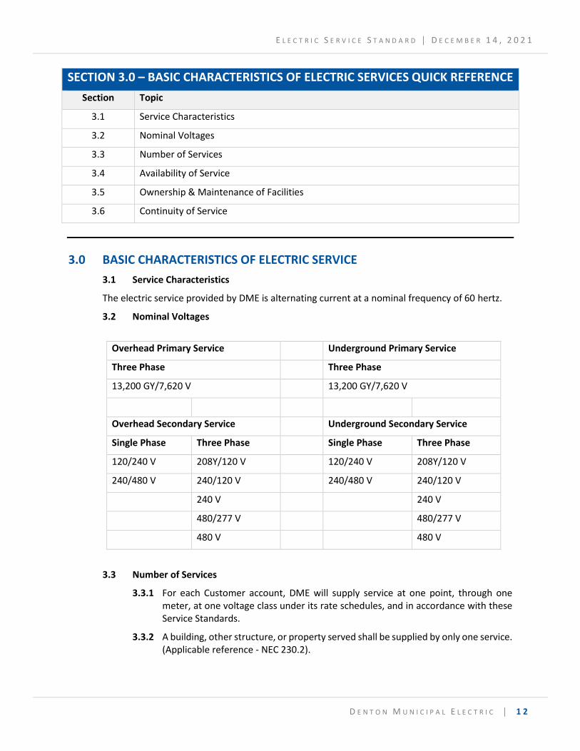
SECTION 3.0 – BASIC CHARACTERISTICS OF ELECTRIC SERVICES QUICK REFERENCE
Section Topic
3.1 Service Characteristics
3.2 Nominal Voltages
3.3 Number of Services
3.4 Availability of Service
3.5 Ownership & Maintenance of Facilities
3.6 Continuity of Service
3.0 BASIC CHARACTERISTICS OF ELECTRIC SERVICE
3.1 Service Characteristics
The electric service provided by DME is alternating current at a nominal frequency of 60 hertz.
3.2 Nominal Voltages
Overhead Primary Service Underground Primary Service
Three Phase Three Phase
13,200 GY/7,620 V 13,200 GY/7,620 V
Overhead Secondary Service Underground Secondary Service
Single Phase Three Phase Single Phase Three Phase
120/240 V 208Y/120 V 120/240 V 208Y/120 V
240/480 V 240/120 V 240/480 V 240/120 V
240 V 240 V
480/277 V 480/277 V
480 V 480 V
3.3 Number of Services
3.3.1 For each Customer account, DME will supply service at one point, through one meter, at one voltage class under its rate schedules, and in accordance with these Service Standards.
3.3.2 A building, other structure, or property served shall be supplied by only one service. (Applicable reference - NEC 230.2).
E L E C T R I C S E R V I C E S T A N D A R D │ D E C E M B E R 1 4 , 2 0 2 1
D E N T O N M U N I C I P A L E L E C T R I C │ 1 3
Where exceptions are made, Customer and DME must agree to the exception, and all costs for additional services will be the responsibility of the Customer. In each case, DME engineering should be consulted early in the design process to avoid delays or revisions to the service.
3.3.3 Exceptions to this rule are found in NEC 230.2 (A) – (D) and include the following:
3.3.3.1 Special conditions requiring emergency systems, fire pumps, standby systems, enhanced reliability systems, or parallel power production.
3.3.3.2 Multiple-occupancy buildings where there is no available space for service equipment accessible to all occupants; or a single building or other structure sufficiently large to make two or more services necessary.
3.3.3.3 Where the capacity requirements of the customer are in excess of 2000 amperes at 1000V or less; or in excess of the current and voltages that DME normally supplies.
3.3.3.4 Where the power requirements include different voltages, frequencies, or phases, such that multiple services are warranted.
3.4 Availability of Service
Service may not be readily available in all areas served by DME. The Customer shall consult with DME prior to requesting service to determine possible costs, and timelines for extension. See Appendix A for a map of the DME certification area. DME provides electric service at DME's standard nominal voltages. Not all standard voltages are available at every location. If a Retail Customer requests a voltage that is non-standard or not available for a specific load or location, such voltage may be provided by DME at the expense of the requesting party. The Customer should obtain from DME the phase and voltage of the service availability before committing to the purchase of motors or other equipment.
3.5 Ownership & Maintenance of Facilities
DME shall retain the ownership of all material and facilities on the utility side of the Point of Delivery for the distribution of electric energy, whether or not the same have been fully or partially paid for by the Customer through Aid-in-Construction at the time of installation. All lines and facilities constructed or installed by DME or by the customer for DME are the property of DME. DME will install or direct installation and maintenance of the electric supply lines and service installations on DME’s side of the Point of Delivery. DME will not install, maintain, or own any facilities or devices except meters, on customer's side of the Point of Delivery.
3.6 Continuity of Service
3.6.1 Reasonable Diligence
DME uses reasonable diligence in accordance with standard utility practices to provide continuous and adequate service in accordance with the Electric Service Standards, as set forth herein, but does not warrant or represent that irregularities or interruptions will not occur.
E L E C T R I C S E R V I C E S T A N D A R D │ D E C E M B E R 1 4 , 2 0 2 1
D E N T O N M U N I C I P A L E L E C T R I C │ 1 4
3.6.2 Service Interruptions
3.6.2.1 Service interruptions may occur. Customer is responsible for installing and maintaining protective devices as are recommended or required by the most current edition of the National Electrical Code as are necessary or advisable to protect Customer's equipment or processes during irregular or interrupted service including, but not limited to, voltage and wave form irregularities, or the failure of part or all of the electrical service. When interruptions do occur DME shall re-establish service as soon as practicable.
3.6.2.2 DME may interrupt service to provide necessary civil defense or other emergency service in the event of a national emergency or local disaster. DME may also interrupt service as necessary for maintenance, repairs, construction, moving of buildings or oversized objects, relocation or changes of facilities, to prevent or alleviate an emergency which may disrupt operation of all or any portion of DME's system, to lessen or remove risk of harm to life or property, to aid in the restoration of electric service, on occasions when any DME wholesale power suppliers fails to deliver sufficient power and/or energy to DME, if ordered to do so by the Electric Reliability Council of Texas, and on failure of all or part of the electric transmission grid of Texas.
3.6.3 Investigation of Service Interruptions & Irregularities:
DME will investigate service interruptions and irregularities reported by a Customer. Such investigation normally terminates at the Point of Delivery. If standard service voltage exists at this point and DME's service facilities are in good condition, the Customer shall be so advised. DME shall not be obligated to inspect Customer's conductors, installation, or equipment.
E L E C T R I C S E R V I C E S T A N D A R D │ D E C E M B E R 1 4 , 2 0 2 1
D E N T O N M U N I C I P A L E L E C T R I C │ 1 5
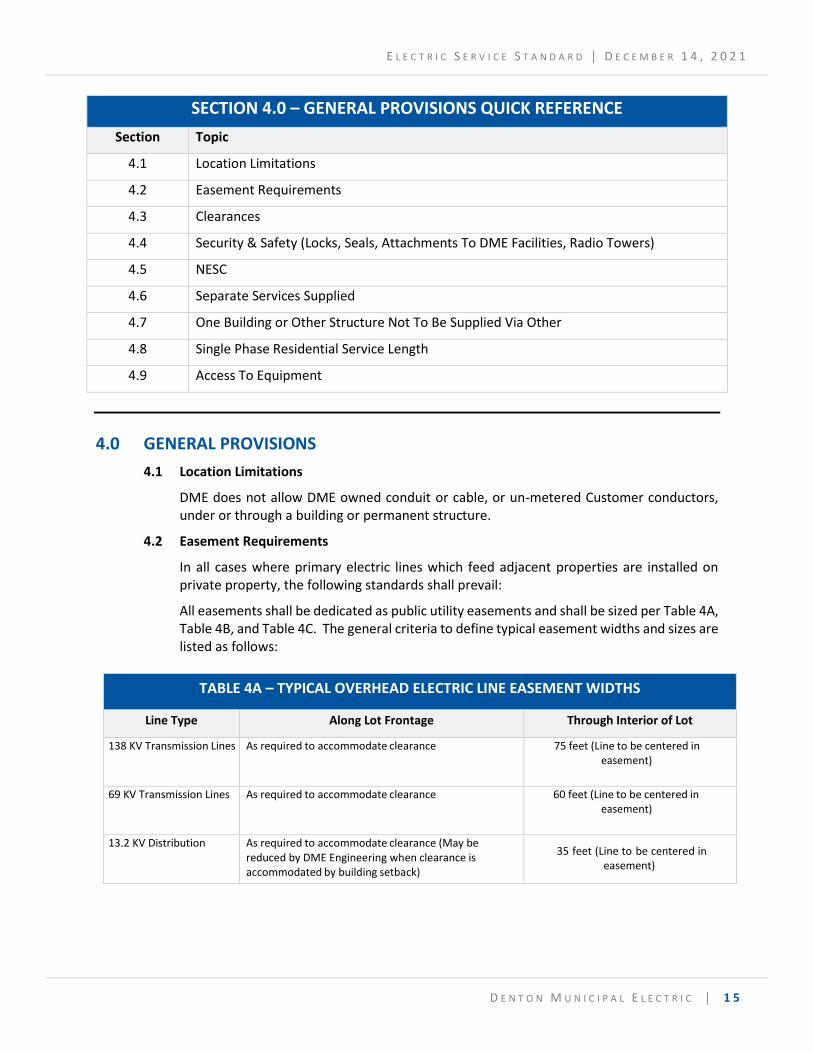
SECTION 4.0 – GENERAL PROVISIONS QUICK REFERENCE
Section Topic
4.1 Location Limitations
4.2 Easement Requirements
4.3 Clearances
4.4 Security & Safety (Locks, Seals, Attachments To DME Facilities, Radio Towers)
4.5 NESC
4.6 Separate Services Supplied
4.7 One Building or Other Structure Not To Be Supplied Via Other
4.8 Single Phase Residential Service Length
4.9 Access To Equipment
4.0 GENERAL PROVISIONS
4.1 Location Limitations
DME does not allow DME owned conduit or cable, or un-metered Customer conductors, under or through a building or permanent structure.
4.2 Easement Requirements
In all cases where primary electric lines which feed adjacent properties are installed on private property, the following standards shall prevail:
All easements shall be dedicated as public utility easements and shall be sized per Table 4A, Table 4B, and Table 4C. The general criteria to define typical easement widths and sizes are listed as follows:
TABLE 4A – TYPICAL OVERHEAD ELECTRIC LINE EASEMENT WIDTHS
Line Type Along Lot Frontage Through Interior of Lot
138 KV Transmission Lines As required to accommodate clearance 75 feet (Line to be centered in easement)
69 KV Transmission Lines As required to accommodate clearance 60 feet (Line to be centered in easement)
13.2 KV Distribution As required to accommodate clearance (May be reduced by DME Engineering when clearance is accommodated by building setback)
35 feet (Line to be centered in easement)
E L E C T R I C S E R V I C E S T A N D A R D │ D E C E M B E R 1 4 , 2 0 2 1
D E N T O N M U N I C I P A L E L E C T R I C │ 1 6
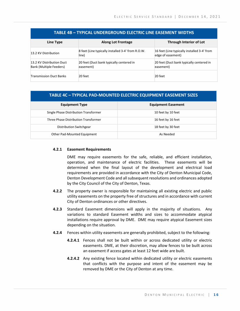
TABLE 4B – TYPICAL UNDERGROUND ELECTRIC LINE EASEMENT WIDTHS
Line Type Along Lot Frontage Through Interior of Lot
13.2 KV Distribution 8 feet (Line typically installed 3-4' from R.O.W. line)
16 feet (Line typically installed 3-4' from edge of easement)
13.2 KV Distribution Duct Bank (Multiple Feeders)
20 feet (Duct bank typically centered in easement)
20 feet (Duct bank typically centered in easement)
Transmission Duct Banks 20 feet 20 feet
TABLE 4C – TYPICAL PAD-MOUNTED ELECTRIC EQUIPMENT EASEMENT SIZES
Equipment Type Equipment Easement
Single Phase Distribution Transformer 10 feet by 10 feet
Three Phase Distribution Transformer 16 feet by 16 feet
Distribution Switchgear 18 feet by 30 feet
Other Pad-Mounted Equipment As Needed
4.2.1 Easement Requirements
DME may require easements for the safe, reliable, and efficient installation, operation, and maintenance of electric facilities. These easements will be determined when the final layout of the development and electrical load requirements are provided in accordance with the City of Denton Municipal Code, Denton Development Code and all subsequent resolutions and ordinances adopted by the City Council of the City of Denton, Texas.
4.2.2 The property owner is responsible for maintaining all existing electric and public utility easements on the property free of structures and in accordance with current City of Denton ordinances or other directives.
4.2.3 Standard Easement dimensions will apply in the majority of situations. Any variations to standard Easement widths and sizes to accommodate atypical installations require approval by DME. DME may require atypical Easement sizes depending on the situation.
4.2.4 Fences within utility easements are generally prohibited, subject to the following:
4.2.4.1 Fences shall not be built within or across dedicated utility or electric easements. DME, at their discretion, may allow fences to be built across an easement if access gates at least 12 feet wide are built.
4.2.4.2 Any existing fence located within dedicated utility or electric easements that conflicts with the purpose and intent of the easement may be removed by DME or the City of Denton at any time.
E L E C T R I C S E R V I C E S T A N D A R D │ D E C E M B E R 1 4 , 2 0 2 1
D E N T O N M U N I C I P A L E L E C T R I C │ 1 7
4.2.4.3 DME is under no obligation to repair or replace any fence that is damaged or removed that encroaches within a dedicated easement for the purposes of installing, operating, maintaining, inspecting, repairing, and replacing electric facilities within the dedicated easement.
4.2.5 DME employees shall have the authority to enter premises at any reasonable time in the regular line of duty for the purpose of installing, operating, maintaining, inspecting, repairing, and replacing any DME owned electric line or electric meter, etc. The property owner and occupant are responsible for any construction activities occurring over or within any on-site utility in a utility easement.
4.2.6 If utility inspection or repair or reconstruction is necessary, any pavement, structure, or improvement damaged within a dedicated utility or electric easement, shall not be the responsibility of DME for any repairs, but shall be the sole responsibility of the owner.
4.2.7 The landowner assumes responsibility for any and all improvements placed within a utility or electric easement at their own risk. Additionally, the provisions of this section do not permit or supersede the limits and restrictions prescribed by the conditions of any existing utility easement for allowing improvements to be placed within utility easements.
4.2.8 The following shall not be installed or planted within a utility or electric easement without approval from DME Engineering:
4.2.8.1 Trees; and
4.2.8.2 Any structures, including retaining walls and signs. No part of a structure, including its underground foundation, shall encroach into an easement.
4.2.9 The following items are typically allowed to be installed within a utility or electric easements:
4.2.9.1 Drive approaches and parking lots (alignment within drive aisles is preferred)
4.2.9.2 Sidewalks; and
4.2.9.3 Grass and small shrubbery.
4.3 Clearances
4.3.1 Overhead Distribution Lines & Facilities
Vertical clearance shall meet or exceed the distances shown in Appendix B, Figure B1. Horizontal clearance shall meet or exceed the distances shown in Appendix B, Figure B2.
4.3.2 Underground Lines & Pad-mount Equipment
DME requires a clearance from all underground lines and pad-mounted equipment. Distances vary and details of DME’s required clearances are provided in Appendix B, Figures B3, B4, B5, B6, B7 & B9. Service will not be connected without adequate clearances.
E L E C T R I C S E R V I C E S T A N D A R D │ D E C E M B E R 1 4 , 2 0 2 1
D E N T O N M U N I C I P A L E L E C T R I C │ 1 8
For equipment in service, in non-emergency situations, when availability of electric service to Customers is not in immediate jeopardy, DME will provide written notice of a clearance violation and allow the property owner seven (7) days to remedy the situation. If that does not occur, or the property owner has not demonstrated to DME’s satisfaction that he is making a reasonable attempt to provide the necessary clearance(s) in a timely fashion, DME will either remove the obstruction at the property owner’s expense or terminate service. In the case of an outage to Customers or an emergency, DME reserves the right to immediately, without notice to the property owner, remove any item or obstruction that restricts access to electric facilities at the property owner’s expense. DME is not responsible for any items or obstructions removed from easements.
4.3.3 Customer Equipment & Facilities -
The Customer's facilities/installations shall maintain clearances from DME electric distribution overhead facilities as required in Section 234 of the NESC. In addition, the Customer’s facilities shall not be installed under or over DME overhead distribution facilities and shall maintain minimum clearances as shown in Appendix B, Figures B1 thru B9 from overhead and underground DME distribution facilities.
See the NESC, DME and the OSHA/TxHSC Working Clearance Envelopes for clearances from Customer facilities. These include, but are not limited to, clearances from Customer’s buildings, parking garages, light poles, signs, billboards, chimneys, radio and television antennas, tanks, swimming pools and other installations. If required by DME, the Customer shall provide DME with a survey showing the proximities of the Customer’s existing and/or proposed facilities to existing DME primary voltage facilities.
4.3.4 Power Line and Pad-mount Equipment Clearance from Trees and Vegetation
4.3.4.1 For reasons of safety and system reliability, DME requires ten (10) feet clearance in all directions from overhead power lines with a nominal voltage of 600 volts to 24,900 volts (3 phase) and a minimum of three (3) feet for voltages 599 volts or less. DME will, at its discretion, trim or remove all trees or other vegetation that grow within this distance. When vegetation is found to be a hindrance to the distribution system or maintenance operations and is removed by DME, DME will not be responsible for the replacement of vegetation that has been removed and will not provide additional landscaping or compensate for loss of vegetation. When trimming trees, DME will follow ANSI A300 standards and make reasonable efforts to preserve the health of trees in accordance with accepted utility industry practice and any applicable legal requirements.
4.3.4.2 Street trees planted within overhead distribution line clearance zones shall be of a species having a mature height of less than 30 feet per the DME Electric Tree Trimming Program guide. Other trees may be allowed within the clearance zone and/or easement of distribution lines if specifically approved by DME Engineering.
E L E C T R I C S E R V I C E S T A N D A R D │ D E C E M B E R 1 4 , 2 0 2 1
D E N T O N M U N I C I P A L E L E C T R I C │ 1 9
4.3.4.3 Trees shall not be planted within the clearance zone and/or easement area (whichever is greater) of transmission lines without written permission from DME Engineering.
4.3.4.4 Vegetation shall follow clearances from pad-mount equipment as shown in Appendix B, Figure B8.
4.3.5 Clearance Zones General Requirements
Unobstructed and adequate space shall be provided for all clearance zones required by this section that will allow ingress and egress for utility-related personnel and equipment to install, operate, maintain, inspect, repair, and replace electric supply and communication lines. Such clearance zone provisions shall be included in the design and construction when real property is developed or altered.
Such clearance zones shall be recorded by the property developer or by the record owner on subdivision plats; or shall be evidenced by written instrument, duly recorded, in the Public Records of Denton County, Texas.
4.3.6 Clearances Statement
The following statement shall be stamped on all Final Plats: “The City of Denton (CoD) has adopted the National Electrical Safety Code (the “Code”). The City of Denton Development Code generally prohibits structures within 17.5 feet on either side of the center line of overhead distribution lines (CoD Development Code, 7.13.5) and within 37.5 feet on either side of the centerline of overhead transmission lines (CoD Development Code, 7.13.4).”
In some instances the Code requires greater clearances. Building permits will not be issued for structures within these clearance areas. Contact the building official with specific questions.
4.4 Security & Safety (Locks, Seals, Attachments to DME facilities, Radio Towers)
Tampering with the meter, metering network, instrument transformers, any conductors carrying un-metered current or the unauthorized breaking of the DME seal is prohibited by law.
Only DME may make the connections (and disconnections) of the Customer's wiring to DME's facilities. In addition, only DME personnel may remove DME meters or break City seals except in cases specifically authorized by DME or its designee. The following will be inspected by DME, or its designee, prior to or at the time of the connection of metering equipment as indicated:
• Meter Socket(s)
• Service Distribution Enclosure
• CT Meter Services
• Old service check (no meter at location)
• Turn on the meter (meter existing)
• Read and change meter
E L E C T R I C S E R V I C E S T A N D A R D │ D E C E M B E R 1 4 , 2 0 2 1
D E N T O N M U N I C I P A L E L E C T R I C │ 2 0
4.5 NESC
The Customer, Developer, and Property Owner are responsible for maintaining the level of care set forth by the currently published National Electrical Safety Code for existing and planned electric utilities in all developments.
4.6 Separate Services Supplied
For all commercial and industrial installations, external disconnects shall be installed by the customer at the building service entrance. Where more than one service is supplied in accordance with 3.3 herein, a permanent tag or directory made of brass and approved by DME, shall be installed at each service disconnect location denoting all other services or feeders, the supplying building or structure, and the area served by each. (Applicable reference - NEC 225.37, NEC 230.2(E))
4.7 One Building or Other Structure Not to be Supplied Through or Under Another
DME owned service conductors shall not pass through the interior or beneath any building or other structure to provide service to another building.
4.8 Single Phase Residential Service Length
The maximum service length permitted is based upon several technical factors including voltage drop, size and type of conductor, and load. The maximum Service distance shall not exceed 250 feet unless reviewed and approved by DME Engineering. See sections 2.44 and 2.49 for the definition of Service Drop and Service Lateral, respectively.
4.9 Access to Equipment
Where DME’s equipment is located on the Customer’s premises, the Customer shall be responsible for maintaining a clear route for access and ensuring that all DME equipment is Readily Accessible for operation, maintenance, inspection, testing, repair and replacement.
E L E C T R I C S E R V I C E S T A N D A R D │ D E C E M B E R 1 4 , 2 0 2 1
D E N T O N M U N I C I P A L E L E C T R I C │ 2 1
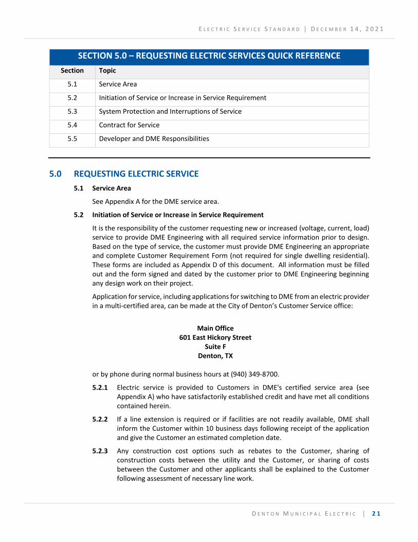
SECTION 5.0 – REQUESTING ELECTRIC SERVICES QUICK REFERENCE
Section Topic
5.1 Service Area
5.2 Initiation of Service or Increase in Service Requirement
5.3 System Protection and Interruptions of Service
5.4 Contract for Service
5.5 Developer and DME Responsibilities
5.0 REQUESTING ELECTRIC SERVICE
5.1 Service Area
See Appendix A for the DME service area.
5.2 Initiation of Service or Increase in Service Requirement
It is the responsibility of the customer requesting new or increased (voltage, current, load) service to provide DME Engineering with all required service information prior to design. Based on the type of service, the customer must provide DME Engineering an appropriate and complete Customer Requirement Form (not required for single dwelling residential). These forms are included as Appendix D of this document. All information must be filled out and the form signed and dated by the customer prior to DME Engineering beginning any design work on their project.
Application for service, including applications for switching to DME from an electric provider in a multi-certified area, can be made at the City of Denton’s Customer Service office:
Main Office
601 East Hickory Street Suite F
Denton, TX
or by phone during normal business hours at (940) 349-8700.
5.2.1 Electric service is provided to Customers in DME's certified service area (see Appendix A) who have satisfactorily established credit and have met all conditions contained herein.
5.2.2 If a line extension is required or if facilities are not readily available, DME shall inform the Customer within 10 business days following receipt of the application and give the Customer an estimated completion date.
5.2.3 Any construction cost options such as rebates to the Customer, sharing of construction costs between the utility and the Customer, or sharing of costs between the Customer and other applicants shall be explained to the Customer following assessment of necessary line work.
E L E C T R I C S E R V I C E S T A N D A R D │ D E C E M B E R 1 4 , 2 0 2 1
D E N T O N M U N I C I P A L E L E C T R I C │ 2 2
DME will follow the PUC Chapter 25 Substantive Rules Applicable to Electric Service providers, Subchapter B, Paragraph 25.27 for Full Switchovers and will not allow for partial switchovers.
5.3 System Protection and Interruptions of Service
5.3.1 DME does not guarantee service against interruptions, irregularities, or fluctuations.
5.3.2 DME is not liable for any damages caused by interruptions, irregularities, or fluctuations.
5.3.3 It is the Customer’s responsibility to protect their equipment against any service irregularity including, but not limited to, over-currents, unbalanced loads, unbalanced voltages, single phasing conditions, over-voltages, under-voltages, surges, blackouts, or any other service irregularity.
5.4 Contract for Service
5.4.1 Acceptance of Service under any rate schedule constitutes acceptance of and agreement to these Electric Service Standards.
5.4.2 Customer’s request for electric service of the character and type available from DME are granted within the limitations of the applicable rate schedule for electric service, the availability of DME facilities, the characteristics of Customer’s electrical load, and these Electric Service Standards.
5.4.3 DME may require special contractual arrangements, which may include additional charges, prior to DME providing electric service if the electric service requested by Customer is 1) not readily available at the service location, 2) is other than that which DME provides under its standard service options or 3) if the service requested is not adequately compensated for by the applicable rate schedule.
5.4.4 By completing and submitting an application for service the customer is agreeing to purchase electric service and abide by DME’s Electric Service Standards.
5.4.5 All of the applicable requirements located in the General Provisions section and throughout the remainder of these standards shall apply.
5.4.6 Any Customer taking electric service from DME, in consideration of DME’s supplying electric service and regardless whether or not such Customer has made application for such electric service, is bound by these Electric Service Standards and is liable to DME for payment for such electric service under the applicable rate schedule.
5.4.7 Customer assumes all responsibility on Customer's side of the Point of Delivery, excluding DME’s meter (when applicable), for the service supplied or taken as well as for the Customer's installation including appliances and apparatus used in conjunction therewith.
5.5 Developer and DME Responsibilities
5.5.1 The latest edition of all applicable building and safety codes shall be followed in the installation of the electrical - distribution system. These codes include, but are not limited to the following:
E L E C T R I C S E R V I C E S T A N D A R D │ D E C E M B E R 1 4 , 2 0 2 1
D E N T O N M U N I C I P A L E L E C T R I C │ 2 3
Local City of Denton Building and Fire Codes or any other applicable codes or ordinances for the project location.
National Electrical Safety Code (NESC)
National Fire Protection Association (NFPA) 70 / National Electric Code (NEC)
U.S. Occupational Safety and Health Act of 1970 (OSHA)
5.5.2 DME Responsibility – The following shall be performed by, and are the responsibility of DME:
5.5.2.1 Upon the receipt of all necessary information from the Developer, DME Engineering will provide a project drawing showing the route of the conduit line(s), transformer/equipment pad locations, and other pertinent information.
5.5.2.2 Please note, the Developer is responsible for providing all material including conduit, spacers, joints, glue, pulling vaults, pull boxes, switchgear bases, poured in place concrete pads, etc. per DME specifications to install all civil work associated with the project. Pre-cast concrete pads for single phase equipment are permissible.
5.5.2.3 DME’s inspector is to inspect all conduit installations prior to the placing of the backfill. If DME’s inspector is not allowed to inspect the backfill, the Developer can be asked to remove the backfill so a proper inspection of the civil work can be done.
5.5.2.4 DME’s inspector is responsible for approving all field changes and coordinating changes with DME’s Engineering office.
5.5.2.5 DME’s inspector is to inspect all poured concrete pads installations prior to the laying of concrete.
5.5.2.6 After approval of the installed transformer pad(s) and conduit system by the DME inspector, and after the Contractor has signed all appropriate contracts, agreements, easements and has paid any required AIC (Aid-in-Construction), DME will make final electrical connections.
5.5.3 Developer Responsibility – The following shall be performed by, and the responsibility of, the Developer for DME owned facilities on the customer owned property:
5.5.3.1 The Developer is required to provide a completed Customer Requirements Form to DME with all requested information.
5.5.3.2 Unless otherwise noted by DME, the Developer is responsible for the installation of any, and all, civil work required by DME.
5.5.3.3 The Developer is to provide DME a Site Plan, a Dimension Control Plan, an Elevation Plan, and a Grading Plan, in AutoCAD format and load information.
E L E C T R I C S E R V I C E S T A N D A R D │ D E C E M B E R 1 4 , 2 0 2 1
D E N T O N M U N I C I P A L E L E C T R I C │ 2 4
5.5.3.4 The Developer is responsible for providing DME either easement(s) or platted right-of-way, as determined by DME, prior to DME installing any electrical facilities. Easements and/or filed plats shall be done at no cost to DME.
5.5.3.5 Prior to construction starting, the Developer shall attend a pre-construction meeting to discuss and coordinate construction and inspection with DME Engineering and Construction.
5.5.3.6 The Developer is to coordinate with the DME inspector to review the work plan prior to any civil work beginning and again for inspection prior to backfilling of trenches and pouring of concrete transformer pads.
5.5.3.7 The Developer is to provide personnel and vehicular access to the project work site, for DME at all times.
5.5.3.8 The Developer is to be held responsible for the full direction and supervision of all work being performed by his employees, agents, or contractors. The Developer shall also be responsible for the area at all times prior to acceptance, particularly in the prevention of damage to the electrical distribution system by the activities of other trades or utilities.
5.5.3.9 All three phase pads for any type of development are to be poured in-place concrete and are to be constructed by the developer according to DME specifications.
5.5.3.10 All testing of concrete and backfill which is deemed necessary by DME is to be performed by an independent testing laboratory at Developer’s expense.
5.5.3.11 The Developer is to replace, at his expense, any damaged equipment or correct any work not in compliance with the requirements of these specifications, the project sketch, or as specified by DME.
5.5.3.12 The Developer is to furnish equipment and labor to lay out ditch, set grade, dig ditches, place conduit in trench, backfill trench with approved fill to proper compaction, set or pour transformer pads and place electrical connection boxes. The trench lines shall run in as straight alignment as practicable.
5.5.3.13 The Developer is to complete rough site grading, establish final grade at pad-mounted equipment locations and clear these locations of any obstructions. Any change in final grade which requires the lowering or raising of electrical conductors or associated equipment will be done at the expense of the Developer.
5.5.3.14 Developer will be responsible to set base or ground sleeves for fuse cabinets, primary connection cabinets, and streetlight boxes.
5.5.3.15 Minimum vertical crossing clearance of electrical conduits from other utilities’ conduits, pipes, cables and wires is twelve (12) inches. Any exception to this requirement will need to be discussed and agreed upon with DME prior to installing the conduit.
E L E C T R I C S E R V I C E S T A N D A R D │ D E C E M B E R 1 4 , 2 0 2 1
D E N T O N M U N I C I P A L E L E C T R I C │ 2 5
5.5.3.16 Minimum vertical and/or horizontal longitudinal clearance from other utility’s conduits pipes, cable and wires is twelve (12) inches. Any exception to this requirement will need to be discussed and agreed upon with DME prior to installing the conduit.
5.5.3.17 No foreign pipes, conduits, wires, or cables are permitted under DME’s transformers or other pad mounted equipment pads.
5.5.3.18 Joint use trench will be determined by DME on a case-by-case basis. In no case shall other utilities be longitudinally installed directly above DME electric facilities, but shall be offset per DME requirements.
5.5.3.19 Backfilling of conduit trenches under paved areas, around conduit bends at riser poles and under transformer pad area is to be compacted to 95% of the density of the surrounding undisturbed soil as per ASTM D 698. Stabilization must be uniform to bottom of ditch. Alternative stabilization methods for backfilling around conduit bends under transformer pads consist of two (2) sacks of cement mixed with earth backfill or the pouring of concrete backfill with transformer pad.
An alternative method for backfilling around conduit bends consists of concrete backfill with bend. The method used will be at the discretion of DME.
5.5.3.20 Poured concrete transformer pads are to be installed such that the top of the pad is a minimum of six (6”) inches above finished grade. No transformer pad shall be installed below finished grade of the surrounding area.
5.5.3.21 Pre-cast transformer pads are to be installed such that the top of the pad is a minimum of four (4”) inches above finished grade. No transformer pad shall be installed below finished grade of the surrounding area.
5.5.3.22 Transformer pads are to have a clear area surrounding the pad installation for safety, operation, and maintenance purposes. Reference clearances for distribution equipment in Appendix B.
5.5.3.23 Piers may be required on all transformer pads as determined by DME Engineering. The depth of piers shall extend to rock or a change in soil conditions sufficient to bear the load of pad and transformer to prevent settlement due to undercutting for conduit bend installations or washing due to drainage.
5.5.3.24 The Developer has the option of installing manufactured transformer pads or poured in-place pads for single phase residential subdivisions. However, where the terrain will not permit the installation of a manufactured transformer pad as determined by DME, the Developer is to install a poured in place transformer pad. For commercial installations all three-phase pads must be poured in place.
E L E C T R I C S E R V I C E S T A N D A R D │ D E C E M B E R 1 4 , 2 0 2 1
D E N T O N M U N I C I P A L E L E C T R I C │ 2 6
5.5.3.25 Concrete forms are to be tight and aligned so that when forms are removed the finished surface shall require little, if any, corrective measures. Concrete work is to have an acceptable finish free of honeycombs, sharp, or irregular surfaces.
5.5.3.26 Developer is to pull a mandrel through each conduit to check and clear blockage and leave a pull tape in each conduit. Mandrel shall be furnished by Developer. Conduit shall be plugged at both ends.
E L E C T R I C S E R V I C E S T A N D A R D │ D E C E M B E R 1 4 , 2 0 2 1
D E N T O N M U N I C I P A L E L E C T R I C │ 2 7
SECTION 6.0 – TYPES OF PERMANENT ELECTRIC DISTRIBUTION SERVICES QUICK REFERENCE
Section Topic
6.1 Overhead Service
6.2 Underground Service
6.3 Reserve Capacity
6.0 TYPES OF PERMANENT ELECTRIC DISTRIBUTION SERVICE
6.1 Overhead Service
6.1.1 Residential
6.1.1.1 General
Electric service from overhead distribution facilities is available to Customers who meet the requirements of these Electric Service Standards. DME may refuse to provide overhead service in any area where DME has or expects to have substantial investment in underground distribution facilities or is required by City codes or guidelines to place new service underground.
6.1.1.2 Accessibility
The service drop conductors must be attached to a permanent building or structure nearest DME’s designated facilities (poles). Where DME’s equipment is located on the Customer’s premises, the Customer shall be responsible for clearing the route for access and making all equipment Readily Accessible for operation, maintenance and replacement. DME facilities (except meters) will be placed only in locations that are always vehicle accessible. This includes along public streets / rights of way, in alleys, along private streets and drives and should be at least 20 feet wide and have 35 feet of vertical clearance.
6.1.1.3 Grounding & Bonding
Electric services must be grounded/bonded in accordance with the NEC. This includes but is not limited to service equipment, raceways, service distribution enclosures, junction boxes wireways, enclosures and service conductors.
6.1.1.4 Meter Loop Location
6.1.1.4.1 Building – the meter location is normally located on the exterior of the building on the first floor or ground level. Meter loops must not be installed on portable buildings, mobile homes, or similar structures not legally part of the property.
E L E C T R I C S E R V I C E S T A N D A R D │ D E C E M B E R 1 4 , 2 0 2 1
D E N T O N M U N I C I P A L E L E C T R I C │ 2 8
6.1.1.4.2 Non-building – shall meet the following requirements:
6.1.1.4.2.1 Be installed on 6” minimum diameter pole/post or on a rack
6.1.1.4.2.2 Pole/post or rack must consist of treated wood or non-corrosive metal.
6.1.1.4.2.3 Poles/posts shall be installed a minimum of 3’ deep encased in concrete.
6.1.1.4.2.4 Racks shall be installed with sufficient bracing and shall be stationery.
6.1.1.4.2.5 Does not apply to temporary services.
6.1.1.5 Conductors & Clearances
6.1.1.5.1 DME shall furnish and install conductors from DME supply line to Customer provided service conductors. Customer provided service conductors shall be at the Weatherhead or pole/rack location. DME will make all connections to Customer’s conductors.
6.1.1.5.2 Clearances for conductors and attachments shall meet the NESC (Section 23) requirements and shall be maintained at all times. (See Appendix B, Figures 1 and 2)
6.1.1.6 Anchorage – The Customer must make provisions for the dead-end attachment to be securely attached to the structural frame of the building using a minimum ½” diameter threaded bolt with nut and washers. (per City of Denton Building Code)
6.1.1.7 Weatherhead - the Weatherhead shall be approved weatherproof construction and installed to prevent the entrance of rain. Customer conductors must extend a minimum of 18” from the Weatherhead.
6.1.1.8 Service Length – measured horizontally/radially from DME pole serving load
6.1.1.8.1 Maximum 250 feet. Service drops in excess of 250 feet must be approved be DME.
6.1.2 Accessory Dwelling Unit (ADU)
Denton Development Code, Subchapter 5.4.4, allows one ADU per lot where the principal use is a single-family detached dwelling. The ADU may be attached or detached from the principal service. For an ADU attached to or created within a single-family dwelling, the ADU meter will be installed on the principal dwelling unit within 10’ of the principal meter. The Point of Delivery will be the Weatherhead.
For detached ADU, the ADU meter may be installed on the principal dwelling unit within 10’ of the principal meter, or on the detached ADU. For meter installation on a detached ADU, all Residential Overhead Service requirements apply. The Point of Delivery will be the Weatherhead.
E L E C T R I C S E R V I C E S T A N D A R D │ D E C E M B E R 1 4 , 2 0 2 1
D E N T O N M U N I C I P A L E L E C T R I C │ 2 9
6.1.3 Commercial Service
6.1.3.1 Accessibility
The service drop conductors must be attached to a permanent building or structure nearest DME’s designated facilities (poles). Where DME’s equipment is located on the Customer’s premises, the Customer shall be responsible for clearing the route for access and making all equipment Readily Accessible for operation, maintenance and replacement.
Access requirements are provided in Appendix B. DME facilities will be placed only in locations that are always vehicle accessible. This includes along public streets / rights of way, in alleys, along private streets and drives and must be at least 20 feet wide and have 35 feet of vertical clearance.
6.1.3.2 Grounding & Bonding
Electric services must be grounded/bonded in accordance with the NEC. This includes but is not limited to service equipment, raceways, service distribution enclosures, junction boxes wireways, enclosures and service conductors.
6.1.3.3 Meter Loop Location
6.1.3.3.1 Building – the meter location should normally be on the exterior of the building on the first floor or ground level. Meter loops must not be installed on modular or manufactured housing, portable buildings, mobile homes, or similar structures not legally part of the property.
6.1.3.3.2 Non-building – shall meet the following requirements:
6.1.3.3.2.1 Be installed on 6” minimum diameter pole/post or on a rack
6.1.3.3.2.2 Consist of treated wood or non-corrosive metal.
6.1.3.3.2.3 Poles/posts shall be installed a minimum of 3’ deep encased in concrete.
6.1.3.3.2.4 Racks shall be installed with sufficient bracing and shall be stationery.
6.1.3.4 Conductors & Clearances
6.1.3.4.1 DME shall furnish and install conductors from DME supply line to Customer provided service conductors. Customer provided services conductors shall be at the Weatherhead or pole/rack location. DME will make all connections to Customer’s conductors.
6.1.3.4.2 Clearances for conductors and attachments shall meet the NESC (section 23) requirements and shall be maintained at all times.
6.1.3.5 Anchorage – The Customer must make provisions for the dead-end attachment to be securely attached to the structural frame of the building
E L E C T R I C S E R V I C E S T A N D A R D │ D E C E M B E R 1 4 , 2 0 2 1
D E N T O N M U N I C I P A L E L E C T R I C │ 3 0
using a minimum ½” diameter threaded bolt with nut and washers. (per City of Denton Building Code).
6.1.3.6 Weatherhead - the Weatherhead shall be approved weatherproof construction and installed to prevent the entrance of rain. Customer conductors must extend a minimum of 18” from the Weatherhead.
6.1.3.7 Service Length – measured horizontally/ radially from DME pole serving load.
6.1.3.7.1 Maximum 250 feet. Service drops in excess of 250 feet must be approved be DME.
6.1.4 Multi-family / Apartment
For multi-family dwellings with two (2) or more units on a single, common lot/parcel/tract of property, the Point of Delivery will be the Weatherhead serving a bank of meters for the individual residences in each building. Residential services to multi-family dwellings where each residence is located on its own separate lot/parcel/tract of land, a separate service drop will be provided to each residence (see Section 6.1.1 above).
6.2 Underground Service
6.2.1 Residential
6.2.1.1 General
Electric service from underground distribution facilities is available to Customers who meet the requirements of these Electric Service Standards. In areas served by DME's underground distribution system, phase and voltage of electric service may be limited to that which can be provided from existing facilities. The location and routing of underground distribution facilities will be determined by DME. A Customer may be required to provide, at their expense, pads for pad-mounted transformers, conduit, and other associated equipment prior to commencement of construction.
6.2.1.2 Accessibility - Where DME’s equipment is located on the Customer’s premises, the Customer shall be responsible for clearing the route for access and making all equipment readily accessible for operation, maintenance and replacement. Access requirements are provided in Appendix B.
6.2.1.3 From Secondary Riser – DME will own and install the secondary conduit and cables from the secondary riser to the meter. The Point of Delivery will be the residential meter.
E L E C T R I C S E R V I C E S T A N D A R D │ D E C E M B E R 1 4 , 2 0 2 1
D E N T O N M U N I C I P A L E L E C T R I C │ 3 1
6.2.1.4 From Pad-mounted transformer (or pedestal) - DME will own and install the secondary conduit and cables from the pad-mounted transformer or pedestal to the meter. The Point of Delivery will be the residential meter.
6.2.1.5 Grounding / Bonding - Electric services must be grounded/bonded in accordance with the NEC. This includes but is not limited to service equipment, raceways, service distribution enclosures, junction boxes wireways, enclosures and service conductors.
6.2.1.6 Meter Loop Location
6.2.1.6.1 Meter socket(s) are to be mounted 4’ – 6’ of center above the finished grade, as measured at 3’ in front of the meter, with a minimum of 4’ working space in front of and to either side of the meter.
6.2.1.6.2 Building – the meter location should normally be on the exterior of the building. Meter loops must not be installed on portable buildings, mobile homes, or similar structures not legally part of the property.
6.2.1.6.3 Non-building – shall meet the following requirements:
6.2.1.6.3.1 Be installed on 6” minimum diameter pole/post or on a rack
6.2.1.6.3.2 Consist of treated wood or non-corrosive metal.
6.2.1.6.3.3 Poles/posts shall be installed a minimum of 3’ deep encased in concrete.
6.2.1.6.3.4 Racks shall be installed with sufficient bracing and shall be stationary.
6.2.1.7 Clearances for conductors and attachments shall meet the NESC (section 23) requirements and shall be maintained at all times.
6.2.1.8 Service Length
6.2.1.8.1 Maximum 250 feet. Service laterals in excess of 250 feet must be approved be DME
6.2.2 Accessory Dwelling Unit (ADU)
Denton Development Code, Subchapter 5.4.4, allows one ADU per lot where the principal use is a single-family detached dwelling. The ADU may be attached or detached from the principal service. For an ADU attached to or created within the principal single-family dwelling, the ADU meter will be installed on the principal dwelling unit within 10’ of the principal DME meter. The property owner is responsible for intercepting the existing service entrance conductors prior to the principal dwelling unit meter, installation of a junction box, meter socket, and necessary conduits and cables from the junction box to the new ADU meter. The installation must meet all applicable codes and DME specifications. DME will
E L E C T R I C S E R V I C E S T A N D A R D │ D E C E M B E R 1 4 , 2 0 2 1
D E N T O N M U N I C I P A L E L E C T R I C │ 3 2
inspect, and if accepted, DME will own and maintain the service lateral to the ADU meter after installation and the ADU Point of Delivery will be the DME meter.
For detached ADU, the ADU meter may be installed on the principal dwelling unit within 10’ of the principal meter, or on the detached ADU. For meter installation on a detached ADU, the property owner will install meter socket, conduit and cables from the DME transformer or pedestal to the new ADU meter. DME will inspect, and if accepted, DME will own and maintain the service lateral to the ADU meter after installation and the ADU Point of Delivery will be the DME meter.
6.2.3 Multi-family / Apartment
For multi-family dwellings with two (2) or more units on a single, common lot/parcel/tract of property, the Point of Delivery will be the secondary spades of the DME owned pad-mount transformer or secondary pedestal. The developer will be responsible for the secondary conduits and cables from the pad-mount transformer to the meter bank or individual meter sockets.
6.2.3.1 The number and size of secondary connections available in DME transformers is dependent on the size and voltage of the transformer to be installed, which is determined by DME. If the Customer-owned secondary cables exceed the transformer limit, a secondary connection cabinet may be required (see section 6.2.6).
6.2.3.2 Where more than one meter is installed, or the meter is not within the boundaries of the premise served, each meter socket shall be clearly and permanently marked by the person installing it to plainly show locations served (e.g. the apartment number, suite number or address) by the meter. It shall be the responsibility of the customer/contractor to ensure the accuracy of the markings with respect to the service location. At DME’s option, the customer shall demonstrate and DME shall witness verification of the accuracy of these markings.
6.2.4 Commercial
6.2.4.1 General
Electric service from underground distribution facilities is available to Customers who meet the requirements of these Electric Service Standards. In areas served by DME's underground distribution system, phase and voltage of electric service may be limited to that which can be provided from existing facilities.
The location and routing of underground distribution facilities will be determined by DME. A Customer will be required to provide, at their expense, pads for pad-mounted transformers, conduit, and other associated equipment prior to commencement of construction.
6.2.4.2 Accessibility - Where DME’s equipment is located on the Customer’s premises, the Customer shall be responsible for clearing the route for access and making all equipment readily accessible for operation, maintenance and replacement. Access requirements are provided in Appendix B.
E L E C T R I C S E R V I C E S T A N D A R D │ D E C E M B E R 1 4 , 2 0 2 1
D E N T O N M U N I C I P A L E L E C T R I C │ 3 3
6.2.4.3 From Secondary Riser – DME will install a pedestal at the base of the riser pole and install the secondary riser, cable and pedestal. The Point of Delivery will be secondary pedestal at the base of the riser pole.
6.2.4.4 From Pad-mounted transformer – The Point of Delivery will be the secondary spades of the pad-mounted transformer. The customer is required to install the primary conduit(s) from a DME owned riser pole, pad-mount switch or vault to the customer installed transformer pad per DME specifications. Where only one commercial customer is served from a pad-mounted transformer and cannot be metered with a self-contained meter, DME may install metering current transformers in the secondary compartment of the pad-mounted transformer (see Section 10.2 for further details).
6.2.4.4.1 The number and size of secondary connections available in DME pad-mounted transformers is dependent on the size and voltage of the transformer to be installed, which is determined by DME. If the Customer-owned secondary cables exceed the transformer limit, a secondary connection cabinet may be required (see section 6.2.6).
6.2.4.4.2 Where more than one meter is installed, or the meter is not within the boundaries of the premise served, each meter socket shall be clearly and permanently marked by the person installing it to plainly show locations served (e.g. the suite number or address) by the meter. It shall be the responsibility of the customer/contractor to ensure the accuracy of the markings with respect to the service location. At DME’s option, the customer shall demonstrate and DME shall witness verification of the accuracy of these markings.
6.2.4.5 Grounding / Bonding - Electric services must be grounded/bonded in accordance with the NEC. This includes but is not limited to service equipment, raceways, service distribution enclosures, junction boxes wireways, enclosures and service conductors.
6.2.4.6 Meter Loop Location
6.2.4.6.1 Building – the meter location should normally be on the exterior of the building on the first floor or ground level. Meter loops must not be installed on, portable buildings, mobile homes, or similar structures not legally part of the property.
6.2.4.6.2 Non-building – shall meet the following requirements:
6.2.4.6.2.1 Be installed on 6” minimum diameter pole/post or on a rack
6.2.4.6.2.2 Poles/posts shall consist of treated wood or non-corrosive metal.
6.2.4.6.2.3 Poles/posts shall be installed a minimum of 3’ deep encased in concrete.
E L E C T R I C S E R V I C E S T A N D A R D │ D E C E M B E R 1 4 , 2 0 2 1
D E N T O N M U N I C I P A L E L E C T R I C │ 3 4
6.2.4.7 Racks shall be installed with sufficient bracing and shall be stationery per DME standards. Non-standard racks must be approved by DME.
6.2.5 Subdivisions (2+ detached single-family dwelling)
All new Subdivisions consisting of two (2) or more detached single-family dwellings will be designed by DME as underground electric distribution in accordance with Section 8.4.9 of the Denton Development Code utilizing front lot construction. All conduits, switch pads, and transformer pads will be installed by developer per DME design and specifications. DME will install all cable, switches, transformers, pedestals and associated electrical equipment at the Developer’s cost through Aid-in-Construction. All Developer responsibilities noted in Section 5.5.7 apply.
6.2.6 Secondary Cabinets
When the number and size of secondary cables cannot be connected to DME owned transformers or the number and size of secondary conduits cannot be installed in the secondary enclosure of the DME owned transformer, a separate secondary cabinet, owned by the owner/developer, must be installed. The Point of Delivery will be secondary cabinet. DME will install and own the secondary cables from the DME owned transformer to the secondary cabinet. The secondary enclosure must be lockable. DME will install a lock on all secondary enclosures.
6.3 Reserve Capacity
Reserve Capacity on a second feeder may be available to commercial customers to provide the capability for automatic transfer from a primary distribution feeder to a second distribution feeder. The customer will be responsible for all costs associated with an engineering study, infrastructure installation/upgrade costs and a monthly charge for the reserve capacity. Customers desiring to Reserve Capacity should contact DME Engineering.
E L E C T R I C S E R V I C E S T A N D A R D │ D E C E M B E R 1 4 , 2 0 2 1
D E N T O N M U N I C I P A L E L E C T R I C │ 3 5
SECTION 7.0 –TEMPORARY/SHORT-TERM SERVICE QUICK REFERENCE
Section Topic
7.1 General Conditions
7.2 Overhead Service
7.3 Underground Service
7.4 Location
7.0 TEMPORARY/SHORT-TERM SERVICE
7.1 General Conditions
7.1.1 Temporary – supplying electric service to a site with an active duration of no more than 2 years
7.1.2 Short-term – supplying electric service to a site with an active duration of no more than 90 days.
7.1.3 Availability – DME will provide temporary or short term (single phase or three phase) services where facilities are available and in DME’s opinion is reasonable and practical.
7.1.4 Cost – see Line Extension Policy for applicable costs / aid-in-construction.
7.1.5 Seasonal Service – For services which may be considered as short-term, such as snow cone stands, food stands, Christmas tree lots, festivals, exhibitions or firework stands, etc.
7.1.6 Designations-
7.1.6.1 Home Builder Loops – Are construction service single-phase meter loops to be used exclusively for the construction, addition or remodeling of a single or duplex residence.
7.1.6.2 Temporary Power Loops – Are temporary service single-phase or three-phase meter loops to be used for construction, addition or remodeling of multifamily residence, commercial buildings, temporary offices, signs, seasonal services.
7.1.7 Interim Service – is required for speculative buildings and long-term temporary service.
7.2 Overhead Service
See Section 6.1 for service requirements. See Appendix E for temporary meter construction details.
7.3 Underground Service
See Section 6.2 for service requirements. See Appendix E for temporary meter construction details.
E L E C T R I C S E R V I C E S T A N D A R D │ D E C E M B E R 1 4 , 2 0 2 1
D E N T O N M U N I C I P A L E L E C T R I C │ 3 6
7.4 Location
The temporary power loop shall be located on the property being served and for which application for service has been made. The service line path shall avoid areas where vehicular traffic will occur unless service pole height is sufficient to provide adequate clearance.
E L E C T R I C S E R V I C E S T A N D A R D │ D E C E M B E R 1 4 , 2 0 2 1
D E N T O N M U N I C I P A L E L E C T R I C │ 3 7
SECTION 8.0 – MODIFICATION, RELOCATIONS AND CONVERSIONS
QUICK REFERENCE
Section Topic
8.1 Relocation of Facilities
8.2 Overhead to Underground Conversions
8.0 MODIFICATION, RELOCATIONS AND CONVERSIONS
8.1 Relocation of Facilities
DME will relocate its facilities on Customer’s premises at Customer’s request provided that Customer has (1) provided a satisfactory easement for the new facilities if needed; and (2) paid in advance the estimated costs for the removal of the old facilities, and all costs for the construction of new facilities.
If DME determines it is necessary to move its facilities because Customer fails or refuses to allow DME access to DME’s facilities at any time, then Customer will be responsible for all costs associated with the relocation.
If development requires the relocation of existing electrical facilities, the Customer/Developer will be responsible for all costs associated with the relocation.
The Customer/Developer may elect to use either the estimated cost provided by DME or the actual costs of the relocation. The choice must be made before any work will commence and may not be changed once work has begun. DME will provide an estimate of the relocation cost, which must be paid in full prior to DME commencing work on the relocation. If the estimated cost option is selected and the estimated cost exceeds actual cost, the difference between actual and estimated costs will not be refunded to the Customer. If the actual cost exceeds the estimated cost, there will be no further contributions required of the Customer. If the actual cost option is selected and the estimated cost differs from the actual cost by 10% or more the excess will be refunded or shortages billed to the Customer/Developer.
8.1.1 Line Relocation for Oversized Loads
DME will assist in the transportation of oversized objects under DME overhead facilities by temporarily de-energizing DME facilities or temporarily relocating or raising electric facilities provided that DME receives compensation for all actual costs incurred.
Actual cost shall mean:
8.1.1.1 Total construction costs including but not limited to DME or contract labor (including overheads); materials used, vehicle usage (including mileage); engineering, right of way acquisition and clearing;
8.1.1.2 Cost for Administrative and Billing related activities.
E L E C T R I C S E R V I C E S T A N D A R D │ D E C E M B E R 1 4 , 2 0 2 1
D E N T O N M U N I C I P A L E L E C T R I C │ 3 8
8.2 Overhead to Underground Conversions
8.2.1 Service Conversions. Customer shall be responsible for the full cost of conversion from overhead service to underground service in an area primarily served by overhead power. DME reserves the right to determine whether or not to make the conversion based on location, interferences, and other applicable factors.
8.2.2 Other Conversions. When a Customer or Developer requests a conversion of an existing overhead facility to underground, the Customer or Developer shall be responsible for the full cost of the conversion from overhead to underground. DME reserves the right to determine whether or not to make the conversion based on location, interferences, and other applicable factors. If easements are required to accommodate the conversion, the Customer or Developer shall provide the easements at no cost to DME.
E L E C T R I C S E R V I C E S T A N D A R D │ D E C E M B E R 1 4 , 2 0 2 1
D E N T O N M U N I C I P A L E L E C T R I C │ 3 9
SECTION 9.0 –LIGHTING (ALSO SEPARATE MANUAL) QUICK REFERENCE
Section Topic
9.1 Street Lighting
9.2 Area/Security Lighting (Customer Requested)
9.0 LIGHTING
9.1 Street Lighting
DME will install street lighting on public roads, or streets only at the request and approval of the City of Denton Street Department as required to meet local lighting regulations, including, but not limited to, requirements defined in the Denton Municipal Code and Development Code. Developers will be required to pay 100% of the estimated cost of the street lighting facilities in advance of construction within their development areas. Street lighting facilities will include poles, fixtures, controls, conduit, wiring, and other electric equipment and devices required for the lighting system. Developers will be required to install the conduit and civil work for the lighting system within the development. Poles and fixtures will be of one of the DME standard poles and fixtures available at the time. The estimated cost for the lighting system shall mean the total cost of all construction, including not only the labor and materials used in construction but also engineering, right of way acquisition and clearing, and all other costs directly attributable to the installation.
9.2 Area/Security Lighting (Customer Requested)
DME will construct one overhead span of secondary wire up to 80’ and install a wood pole and lighting fixture (refer to DME rate ordinance, Schedule DD) to provide security lighting per a customer request. The cost of this installation is covered by the monthly lease rate of the lighting fixture. Any Customer requirements beyond this standard shall be at the expense of the Customer. Customer shall pay in advance as non-refundable Aid-in-Construction any excess costs of such lighting construction. For underground services to security lighting, the Customer shall pay in advance as a non-refundable Aid-in-Construction the difference in such costs between the cost of a standard installation and the cost of the underground service installation.
E L E C T R I C S E R V I C E S T A N D A R D │ D E C E M B E R 1 4 , 2 0 2 1
D E N T O N M U N I C I P A L E L E C T R I C │ 4 0
SECTION 10.0 –METERS QUICK REFERENCE
Section Topic
10.1 Residential
10.2 Non-Residential
10.3 Location and Installation of Meter
10.4 Type of Meter and Ownership
10.5 Limitation of Service from Single Meter
10.6 Old, Damaged, Obsolete Equipment
10.0 METERS
10.1 Residential
10.1.1 Customer’s meter shall be installed at a suitable location as determined by DME.
10.1.2 The meter base shall be furnished, owned and installed by the Customer (see Appendix C attached hereto for sizes).
10.1.3 All service taken at the same Point of Delivery will be metered with one meter, or in the case of multiple occupancy, with grouped meters.
10.1.4 Where it is necessary for DME to supply service with more than one transformer, and Customer arranges his service entrance to receive all services at one location, DME may provide totalizing metering at DME’s discretion.
10.1.5 Where additional transformers are used for Customer’s convenience to supply their demand load, and the transformers are not located together, separate meters will be installed. If the transformers are located together and totalizing equipment is used, the totalizing equipment shall be installed at Customer’s expense.
10.2 Non-residential
10.2.1 DME will not allow customer meter bases to be mounted on DME owned pad-mounted transformers or other equipment. For service to one non-residential Customer from a pad-mounted transformer, the Customer shall install a one-inch conduit from the pad-mounted transformer’s secondary compartment to a remotely mounted meter socket. The Customer shall install pull tape in this conduit for DME’s use.
10.2.2 Where it is necessary for DME to supply service with more than one transformer, and Customer arranges his service entrance to receive all services at one location, DME may provide totalizing metering at DME’s discretion.
10.2.3 Where additional transformers are used for Customer’s convenience to supply their demand load, and the transformers are not located together, separate meters will be installed.
E L E C T R I C S E R V I C E S T A N D A R D │ D E C E M B E R 1 4 , 2 0 2 1
D E N T O N M U N I C I P A L E L E C T R I C │ 4 1
If the transformers are located together and totalizing equipment is used, the totalizing equipment shall be installed at Customer’s expense.
10.2.4 For all commercial and industrial installations, a jaw clamping lever bypass handle will be required on each meter base.
10.3 Location and Installation of Meter
Meters and service switches in conjunction with the meter shall be installed in accordance with the latest revision of American National Standards Institute, Incorporated Standard C12 (American National Code for Electricity Metering), and will be Readily Accessible for reading, testing and inspection, and where such activities will cause minimum interference and inconvenience to the Customer. Customer shall provide, at a suitable and easily accessible location, a minimum of four (4) feet of clearance in front of and on either side of the meter base space for installation of meters and other apparatus of DME.
10.3.1 The Customer will be required to furnish and install, without cost to DME, other necessary metering equipment including: (1) meter board, (2) meter loop, (3) meter base, gang or rack (see Appendix C attached hereto for acceptable equipment), (4) metering enclosure, (5) safety service switches, (6) adequate earth ground, (7) an adequate anchor for service drops with centerline of meter height between four (4) and six (6) feet above final grade ground level. All meters shall be located as set forth herein. To meet these requirements, vertical pack meter sets will be limited to a maximum of four (4) positions.
10.3.2 When applications are made to replace meters that have been removed from service, DME may require changes in meter locations should DME find that the existing location is no longer suitable or safe.
10.3.3 Where a change in the meter location on the Customer’s premises is required by DME, changed at the request of the Customer, or changed due to alterations on Customer’s premises, the Customer shall provide and have installed at his expense, all wiring and equipment necessary for relocation the meter.
10.4 Type of Meter and Ownership
DME shall provide, install, own, and maintain all meters necessary for the measurement of electrical energy. Such meters shall be of a standard type, which meet industry standards; however, special meters not conforming to such standards may be used for investigation or for experimental purposes.
10.5 Limitation of service from single meter
No business shall be served from a meter serving a residence unless the residence and business are combined under a single roof. Under those conditions, Commercial rates shall apply to all metered service.
10.6 Old, Damaged, Obsolete Equipment
When DME identifies old, obsolete or damaged meter installations, the Customer will be notified of the conditions. If damage has been caused by Customer, a 90-day duration will be allocated to make necessary repairs. If repairs are not completed and accepted, DME may disconnect service. As determined by DME, DME may replace old, obsolete metering equipment at DME expenses.
E L E C T R I C S E R V I C E S T A N D A R D │ D E C E M B E R 1 4 , 2 0 2 1
D E N T O N M U N I C I P A L E L E C T R I C │ 4 2
SECTION 11.0 – POINT(S) OF DELIVERY QUICK REFERENCE
Section Topic
11.1 POD for Non-Primary Metered Customer
11.2 POD for Primary Metered Customer
11.0 POINT(S) OF DELIVERY (POD)
11.1 POD for Non-Primary Metered Customer
DME shall determine points of delivery for all electric services to be provided by DME. The Point(s) of Delivery listed below are intended to be applicable to the majority of services. Isolated circumstances not covered in this document may require delivery at a point other than as specified herein which point must be approved by DME.
11.1.1 Overhead Areas
Where DME provides service via overhead, the Point of Delivery will be the point of junction between DME service-drop conductors and customer's service-entrance conductors at the Weatherhead.
11.1.2 Underground Areas
11.1.2.1 The Point of Delivery for commercial and industrial facilities will be the secondary terminals of pad-mounted transformers or secondary pedestals.
11.1.2.2 For single-family detached dwellings, or where the single-family dwelling of an attached building is located on a single lot/parcel/tract of land, the Point of Delivery will be at the line side of the meter socket.
11.1.2.3 The Point of Delivery for multi-family dwellings on a single common lot/parcel/tract of land will be the secondary terminals of pad-mounted transformers or secondary pedestals.
11.1.2.4 Other Points of Delivery will be as determined by DME as needed.
11.2 POD for Primary Metered Customer
11.2.1 Overhead Areas
The Point of Delivery will be at the load side terminals of the primary metering set.
11.2.2 Underground Areas
The Point of Delivery will be at the load side of the primary metering cabinet for underground equipment.
E L E C T R I C S E R V I C E S T A N D A R D │ D E C E M B E R 1 4 , 2 0 2 1
D E N T O N M U N I C I P A L E L E C T R I C │ 4 3
11.2.3 Point of Delivery – Primary-voltage Cable to Transformer Vaults:
DME does not allow primary voltage to transformer vaults on any new projects for safety reasons. Where DME-owned primary-voltage cable serves existing transformer vaults with transformers supplying secondary-voltage service to grouped or individual meters, the Point of Delivery will be at the secondary spades of the transformer. All DME owned conductors shall be effectively outside the building.
E L E C T R I C S E R V I C E S T A N D A R D │ D E C E M B E R 1 4 , 2 0 2 1
D E N T O N M U N I C I P A L E L E C T R I C │ 4 4
SECTION 12.0 – CUSTOMER’S ELECTRICAL LOAD QUICK REFERENCE
Section Topic
12.1 Load Balance
12.2 Equipment Necessary to Limit Adverse Effects
12.3 Motors
12.4 Changes in Customer’s Electrical Load
12.5 Access
12.6 Protection of Utilities Facilities on Customer Property
12.7 Customer’s Main Disconnect
12.8 Power Generation Interface
12.9 Grounding
12.0 CUSTOMER'S ELECTRICAL LOAD
12.1 Load Balance
DME requires Customer to control the use of electric energy so that DME's electrical load at the Point of Delivery is in reasonable balance.
12.2 Equipment Necessary to Limit Adverse Effects
12.2.1 DME may require Customer to provide, at Customer's expense, suitable apparatus to limit the effects on DME’s distribution system of voltage fluctuations caused by electric equipment in Customer's installation where Customer is found to be operating electrical equipment which produces voltage fluctuations, interference or distorted wave forms which adversely affect electric service provided by DME to Customers.
12.2.2 In lieu of requesting Customer to install special equipment limiting such adverse effect, DME may, at its option, install at Customer's cost, additional transformer capacity (which may or may not be dedicated solely to the Customer) or other equipment specially designed to reasonably limit such adverse effects.
12.3 Motors
12.3.1 The Customer shall exercise extreme care in the proper selection of motors in order that successful operation and good service will result. The customer shall, prior to ordering or installing any polyphase motors (50 hp or larger) or large single-phase motors (15 hp or larger), notify DME Engineering in order to validate the adequacy of the available electrical service.
12.3.2 Single-phase motors to be served with 120/240V supply lines should be connected for 240V whenever practical to minimize voltage drop in the Customer's wiring system and the supply system. All motors shall have a nameplate and voltage rating compatible with the nominal supply voltage.
E L E C T R I C S E R V I C E S T A N D A R D │ D E C E M B E R 1 4 , 2 0 2 1
D E N T O N M U N I C I P A L E L E C T R I C │ 4 5
They shall also be designated to operate successfully at rated load with variation in the supply voltage of not more than 10 percent above or below the nameplate voltage rating in accordance with National Electrical Manufacturers Association (NEMA) Specifications.
12.3.3 Motor Starting Current and Other Special Equipment Requirements. When planning service, the Customer should consider the current required to start a motor that is appreciably greater than that required for operation at full load after normal speed is reached. While this increase in current is short, it is often enough to cause serious fluctuations in voltage to the Customer using the motor and to other Customers as well. These fluctuations cause objectionable light flickering and disturbances to other types of equipment.
12.3.4 Customers are required to inform DME about any major motor loads that might create a voltage sag or flicker during operation. Generally, motor loads over 50kW/HP are considered to fall in this category. The Customer may be required to take corrective actions to alleviate the service deterioration that may result from the operation of such loads.
12.3.5 If the Customer has primary service of 13.2 kV and motor load(s) exceeding 50HP, the following studies shall be performed and IEEE standards satisfied:
12.3.5.1 Short Circuit and Coordination Study. A Short Circuit and Coordination Study shall be performed by the Customer to determine how to set protective devices in order to minimize the extent of an outage. The choice of the protective devices shall be determined by the requirement that a fault is interrupted within the effected circuit, thereby, minimizing power disruption. Customer shall perform this study starting from their smallest circuit and working their way back to the main breaker. The main breaker shall fully coordinate with DME's feeder/circuit and substation equipment. DME Engineering will provide the relay settings for those feeders/circuits as needed/requested.
12.3.5.2 A Short Circuit and Coordination Study is one of the most important tasks that a Customer can perform that ensures the safety and protection of their personnel and electrical equipment. When an electrical fault or overload causes currents in excess of the interrupting rating of the protective device(s), the consequences can be devastating including injury, damaged electrical equipment, and expensive facility downtime.
12.3.5.3 The IEEE Electrical Power Distribution for Industrial Plants (Red Book) describes the purpose of Electrical Coordination Studies.
12.3.6 Polyphase/Single-Phase Motors. Three-phase service is not readily available in all areas. Before any application of three-phase equipment is made, it is imperative that DME Engineering is consulted to verify service availability. There is no specific rule on allowable starting currents of polyphase or single-phase motors. Poly-phase motors of 50 horsepower and larger and single-phase motors of 15 horsepower and larger may require installation with reduced-voltage starters.
E L E C T R I C S E R V I C E S T A N D A R D │ D E C E M B E R 1 4 , 2 0 2 1
D E N T O N M U N I C I P A L E L E C T R I C │ 4 6
12.3.7 Protective Devices. All motors shall be equipped with effective protection, installed by the Customer, for the motors, the machines they drive, and the wiring. DME strongly recommends that the Customer’s protective devices conform to the requirements of the latest version of the NEC.
For example: The NEC requires that when installing three-phase motors, the Customer should use devices to prevent single-phasing (the loss of one phase either in the Customer’s facilities or DME supply lines). Regardless of the precautions taken by DME and the Customer, this single-phasing may occur; therefore, the Customer should install equipment to protect the Customer’s motor(s). DME is not liable for equipment damage due to single-phasing.
12.4 Changes in Customer’s Electrical Load
12.4.1 DME requires information concerning the nature of a customer’s load and electric service requirements as well as the expected duration of the load. Customer shall give written notice to DME fifteen (15) days in advance of connecting any motors or other devices, which might increase load above the rated capacity of transformer(s) servicing said Customer. If Customer fails to give such notice and an overload condition causes damage to the transformer(s) servicing Customer, then Customer shall pay DME the replacement costs of such transformer prior to the time it was damaged less salvage value.
12.4.2 If in the judgment of DME there is an increase in any electric service requirement for which, under standard engineering practice, it would be desirable to construct additional facilities, then DME may charge Customer for Aid-in-Construction or set an increased minimum rate, up to an amount not to exceed the actual cost of such facilities together with any fixed cost increase charged by DME’s wholesale power supplier as a result of the Customer’s increased load. DME may require the Customer to execute a new contract for electric service specifying appropriate terms including the maximum load, increased minimum load or Aid-in-Construction.
12.5 Access
Customer will allow access to personnel authorized by DME to Customer's premises at all hours to inspect, install, remove, maintain, or replace DME's property, to read DME's meter, and to perform other activities necessary to provide electric service, including tree trimming and tree removal where such trees, in the opinion of DME, constitute a hazard to DME personnel or facilities, or jeopardize the provision of continuous electric service. Refusal on the part of Customer to provide access for the above purposes may, at DME's option, be sufficient cause for discontinuance of service. If services are discontinued by DME due to Customer’s refusal to provide proper access, service will not be restored until the facilities are relocated to provide DME proper access. Such relocation will be at Customers expense.
12.6 Protection of Utilities Facilities on Customer Property
12.6.1 Customer shall use reasonable diligence to protect DME personnel and facilities on Customer's premises.
E L E C T R I C S E R V I C E S T A N D A R D │ D E C E M B E R 1 4 , 2 0 2 1
D E N T O N M U N I C I P A L E L E C T R I C │ 4 7
12.6.2 In the event of loss of or damage to DME facilities on Customer's premises caused by or arising out of carelessness, neglect, or misuse by Customer or unauthorized persons, DME may require Customer to reimburse DME the full costs of such damage.
12.7 Customer’s Main Disconnect
For non-residential applications Customer’s main disconnect switch(es) shall be located on the load side (behind) and next to the DME meter(s) on the outside of the building. However, where the Customer is the only Customer served from a transformer, the meter and disconnect may be located so that they are accessible from outside the Customer’s building by means of a lockbox with a DME lock. The lockbox location shall be clearly visible from the transformer location. In addition, the Customer’s main disconnect location shall also meet the City of Denton Electrical Code Requirements.
12.8 Power Generation Interface
Customers may have many variations in electrical circuits and a multitude of electrical generator types and capacities (including renewable sources) for Customer applications. Therefore, each request for interconnection of Customer-owned power generation facilities with the electrical system must be individually reviewed and approved by DME. This is to ensure that suitable protective devices will be installed and operating procedures for joint use will be followed.
For more information, contact DME and see the DME Distributed Generation Manual.
12.9 Grounding
Electric services, including, but not limited to, service equipment, raceways, service distribution enclosures, junction boxes, wire-ways, enclosures, and any service conductor to be grounded/bonded, shall be grounded/bonded in accordance with the latest edition of the NEC.
EXCEPTION: The grounding/bonding conductors for all services shall be copper only, with a minimum size of #6 AWG copper.
E L E C T R I C S E R V I C E S T A N D A R D │ D E C E M B E R 1 4 , 2 0 2 1
D E N T O N M U N I C I P A L E L E C T R I C │ 4 8
SECTION 13.0 – DISTRIBUTED/CUSTOMER OWNED GENERATION INTERCONNECTION QUICK REFERENCE
Section Topic
13.1 General/Agreements
13.2 Visible and Lockable AC Disconnects
13.3 Interconnection and Parallel Operations
13.4 Stand-Alone Distributed Generation
13.5 Distributed Generation Manual
13.0 DISTRIBUTED / CUSTOMER OWNED GENERATION INTERCONNECTION
(Also see DME Distributed Generation Manual: https://www.cityofdenton.com/.../FY2021-DG-Manual.pdf)
13.1 General/Agreements
Customers requesting interconnection and parallel operation of Distributed Generation (DG) must complete the DME approved Application for Interconnection. DME will allow interconnection for a DG facility, subject to the provision of these Service Standards and all other applicable rules and regulations.
13.2 Visible & Lockable AC Disconnects
Customer must install a manual safety disconnect within four (4) feet of DME’s meter that has a visual break and is easily accessible by DME personnel. Under no circumstances will DG disconnect, equipment, or wire be attached to or inside any DME facilities, including meter sockets, transformers, and switchgears.
13.3 Interconnection and Parallel Operations
13.3.1 Specific information and additional requirements for Distributed Generation are contained in the Distributed Generation Manual located online at the DME website.
13.3.2 DME will conduct internal studies that may include evaluation of electric grid impacts, verify accessibility of equipment, and verify that no direct connection to DME’s meter is used. DME will also review the necessary documents to assure all installs meet current NESC, DME Service Standards, UL1741, and IEEE 1547 Standards.
13.3.3 Distributed Generation over 500 kW will be subject to the necessary pre-interconnection studies, which may include a service study, coordination study, and utility system impact study, as needed in compliance with PUCT Substantive Rules 25.211 and 25.212 or its successor(s).
E L E C T R I C S E R V I C E S T A N D A R D │ D E C E M B E R 1 4 , 2 0 2 1
D E N T O N M U N I C I P A L E L E C T R I C │ 4 9
In instances where such studies are deemed necessary, the scope of such studies shall be based on the characteristics of the particular distributed generation facility to be interconnected and DME’s distribution system at the specific proposed location. The Customer is responsible for all costs associated with the pre-interconnection studies.
13.3.4 Once the study is completed and/or the project has been reviewed by DME, the Customer will pay all necessary costs estimated for construction or extension of DME’s facilities required for interconnection and/or parallel operation.
13.3.5 DME may prevent or disconnect any interconnection of DG facilities, at its sole discretion, due to reasons related to safety concerns, reliability issues, power quality issues, or break of interconnection agreement. No prior notice will be provided to Customer of any disconnection.
13.3.6 Customer must notify DME in writing thirty (30) days in advance of making any change affecting the characteristics, performance, access, or protection of the DG facility, safety disconnect, or meter.
13.3.7 Any connection to the Distribution or Transmission system without proper prior notice and execution of interconnection agreement will result in the immediate disconnection of service. Service will not be restored until any required studies are completed, the installation has been inspected and approved by DME, and an interconnection agreement has been executed.
13.4 Stand-Alone Distributed Generation
Distributed Generation that is not connected to the DME Electric System in any way shall be installed in a manner that no generated power will export to the DME electric system.
13.5 Distributed Generation Manual
Specific information and additional requirements for Stand-Alone Distributed Generation are contained in the Distributed Generation Manual located online at the DME website.
E L E C T R I C S E R V I C E S T A N D A R D │ D E C E M B E R 1 4 , 2 0 2 1
D E N T O N M U N I C I P A L E L E C T R I C │ 5 0
SECTION 14.0 – SMALL CELL INTERCONNECTION QUICK REFERENCE
Section Topic
14.1 Purpose/General Conditions
14.2 Pole Loading Analysis
14.3 Standards
14.4 Metering
14.5 Application for Connection
14.0 SMALL CELL (SC) INTERCONNECTION
14.1 Purpose / General Conditions – Section 14.0 applies to the attachment of communications equipment to DME facilities.
14.2 Pole Loading Analysis – Applicant shall provide pole loading analysis for each location to DME or its designated agent for review.
14.3 Standards – Applicants shall follow construction standards and will be required to secure separate easements. Equipment will not be allowed above the neutral conductor or in the utility space on the pole.
14.4 Metering – three services for each SC owner by type of service will be metered to establish a base monthly usage. All other services of similar type for the SC owner will be billed the base monthly usage.
14.5 Application for connection – Applicants shall submit required documentation for review and approval prior to installation of equipment.
E L E C T R I C S E R V I C E S T A N D A R D │ D E C E M B E R 1 4 , 2 0 2 1
D E N T O N M U N I C I P A L E L E C T R I C │ 5 1
SECTION 15.0 – ELECTRIC VEHICLES QUICK REFERENCE
Section Topic
15.1 Residential
15.2 Commercial
15.3 Inspections
15.0 ELECTRIC VEHICLES
15.1 Residential
At home - Level 1 charging involves powering via a 120 volt typical wall socket. Level 2 charging is from a 240 V AC outlet, and typically with higher amperage. Level 3 charging, also known as DC fast charging, and typically 480 volts, is not allowed at a Residence. DME does not require notification of installation, but Customer should follow all applicable standards and regulations.
15.2 Commercial
15.2.1 Level 1, 2, 3 chargers – all levels are permitted at commercial sites or as stand-alone operations. When Level 3 chargers are installed, Customer must notify DME by using the “Level 3 Charger” application. DME will review and evaluate the application to determine if DME equipment or facilities will require upgrade. If upgrades are required, Customer will be required to pay 100% of upgrade costs.
15.2.2 City owned – the City of Denton reserves the right to construct, own and operate vehicle charging stations.
15.3 Inspections – Periodic inspections may be performed by DME.
E L E C T R I C S E R V I C E S T A N D A R D │ D E C E M B E R 1 4 , 2 0 2 1
D E N T O N M U N I C I P A L E L E C T R I C │ 5 2
16.0 TRANSMISSION & SUBSTATION REQUIREMENTS
16.1 Customers requesting electric service greater than 7 MW may require new facilities to be constructed. Facilities may be distribution, substation and transmission or a combination thereof.
16.2 Commercial or industrial customers with significant electric power requirements should notify DME well before, possibly 36 months, the need for permanent power.
16.3 DME will work with existing and potential customers to meet the electric power requirements.
16.4 Costs for new facilities will be estimated and may lead to negotiated rates and Aid in Construction.
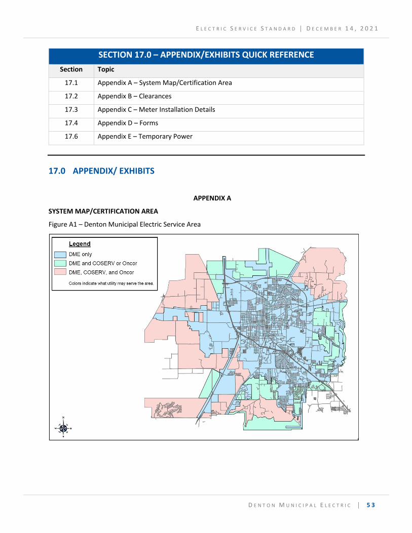
E L E C T R I C S E R V I C E S T A N D A R D │ D E C E M B E R 1 4 , 2 0 2 1
D E N T O N M U N I C I P A L E L E C T R I C │ 5 3
SECTION 17.0 – APPENDIX/EXHIBITS QUICK REFERENCE
Section Topic
17.1 Appendix A – System Map/Certification Area
17.2 Appendix B – Clearances
17.3 Appendix C – Meter Installation Details
17.4 Appendix D – Forms
17.6 Appendix E – Temporary Power
17.0 APPENDIX/ EXHIBITS
APPENDIX A
SYSTEM MAP/CERTIFICATION AREA
Figure A1 – Denton Municipal Electric Service Area
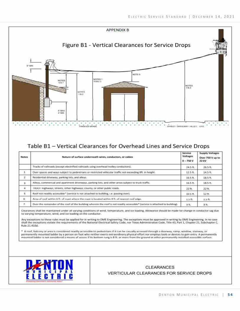
E L E C T R I C S E R V I C E S T A N D A R D │ D E C E M B E R 1 4 , 2 0 2 1
D E N T O N M U N I C I P A L E L E C T R I C │ 5 4
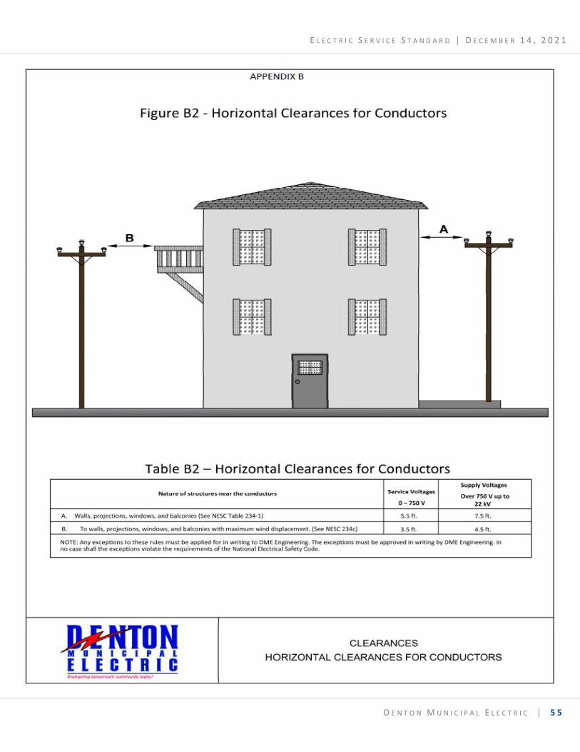
E L E C T R I C S E R V I C E S T A N D A R D │ D E C E M B E R 1 4 , 2 0 2 1
D E N T O N M U N I C I P A L E L E C T R I C │ 5 5
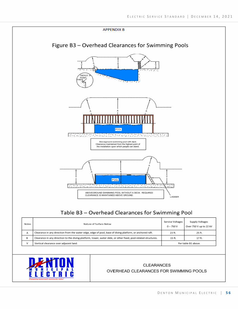
E L E C T R I C S E R V I C E S T A N D A R D │ D E C E M B E R 1 4 , 2 0 2 1
D E N T O N M U N I C I P A L E L E C T R I C │ 5 6
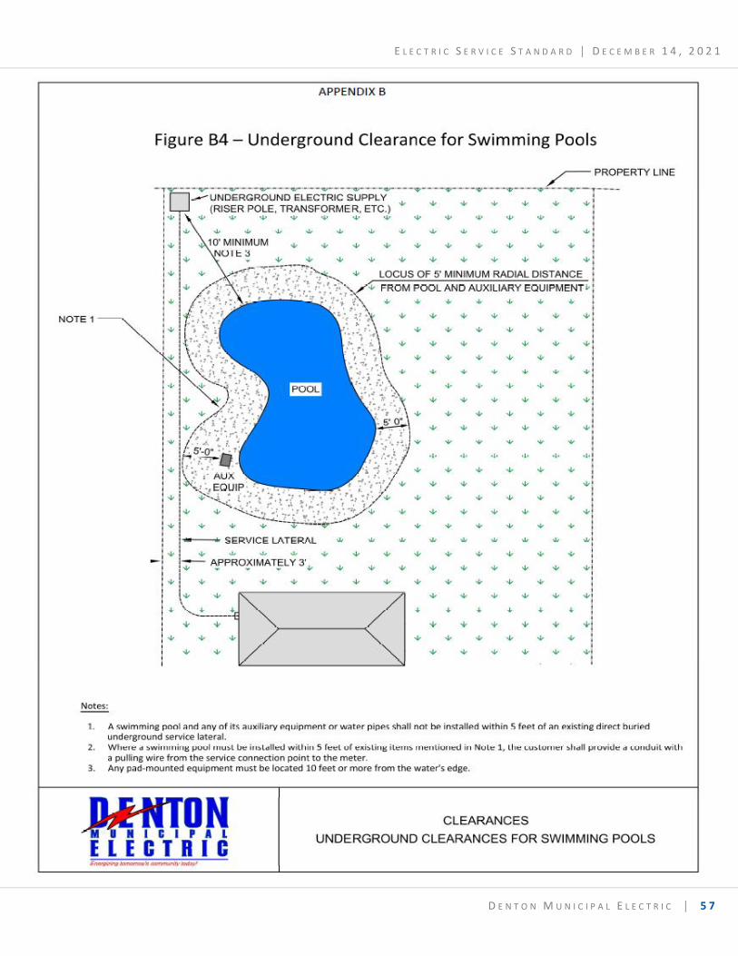
E L E C T R I C S E R V I C E S T A N D A R D │ D E C E M B E R 1 4 , 2 0 2 1
D E N T O N M U N I C I P A L E L E C T R I C │ 5 7
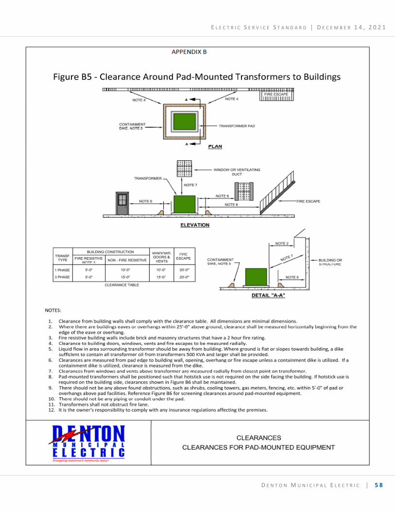
E L E C T R I C S E R V I C E S T A N D A R D │ D E C E M B E R 1 4 , 2 0 2 1
D E N T O N M U N I C I P A L E L E C T R I C │ 5 8
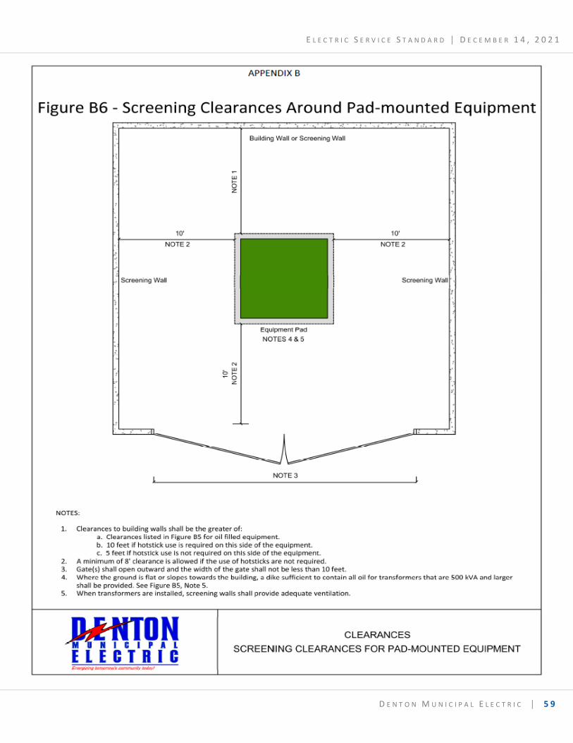
E L E C T R I C S E R V I C E S T A N D A R D │ D E C E M B E R 1 4 , 2 0 2 1
D E N T O N M U N I C I P A L E L E C T R I C │ 5 9
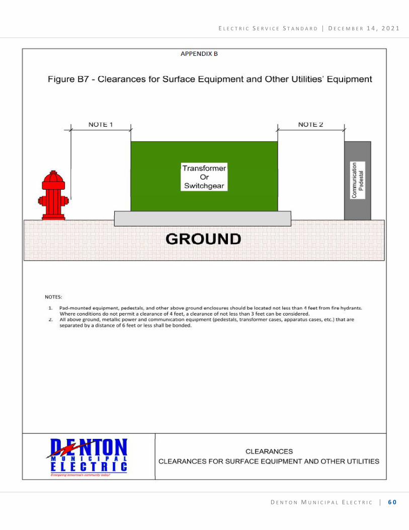
E L E C T R I C S E R V I C E S T A N D A R D │ D E C E M B E R 1 4 , 2 0 2 1
D E N T O N M U N I C I P A L E L E C T R I C │ 6 0
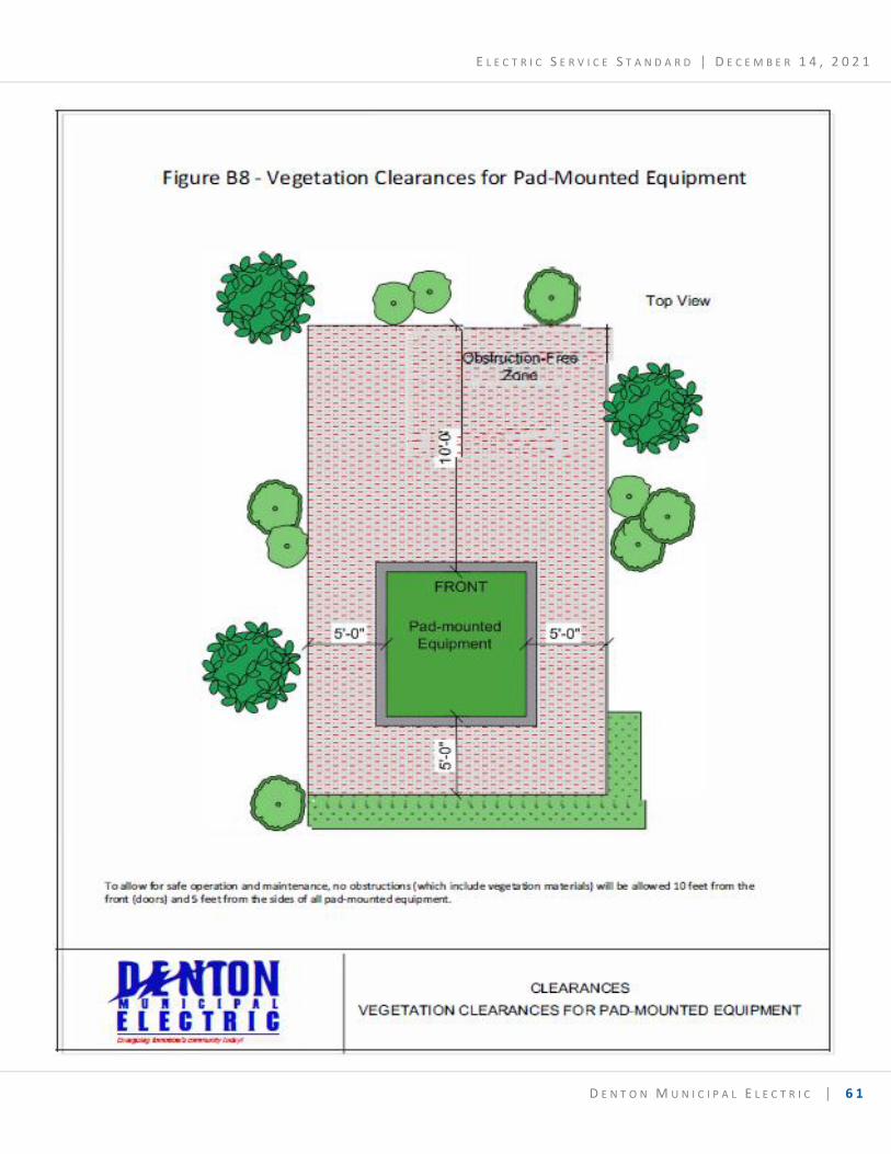
E L E C T R I C S E R V I C E S T A N D A R D │ D E C E M B E R 1 4 , 2 0 2 1
D E N T O N M U N I C I P A L E L E C T R I C │ 6 1
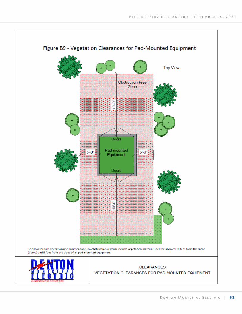
E L E C T R I C S E R V I C E S T A N D A R D │ D E C E M B E R 1 4 , 2 0 2 1
D E N T O N M U N I C I P A L E L E C T R I C │ 6 2
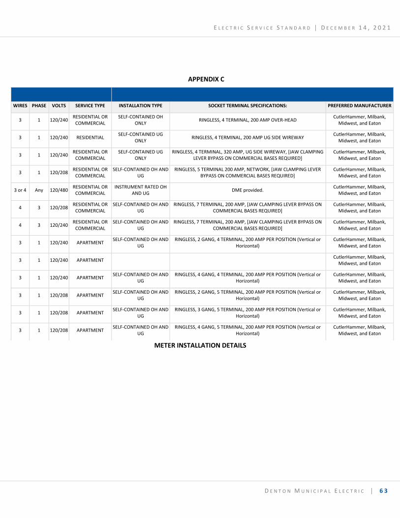
E L E C T R I C S E R V I C E S T A N D A R D │ D E C E M B E R 1 4 , 2 0 2 1
D E N T O N M U N I C I P A L E L E C T R I C │ 6 3
APPENDIX C
METER INSTALLATION DETAILS
WIRES PHASE VOLTS SERVICE TYPE INSTALLATION TYPE SOCKET TERMINAL SPECIFICATIONS: PREFERRED MANUFACTURER
3 1 120/240 RESIDENTIAL OR
COMMERCIAL SELF-CONTAINED OH
ONLY RINGLESS, 4 TERMINAL, 200 AMP OVER-HEAD
CutlerHammer, Milbank, Midwest, and Eaton
3 1 120/240 RESIDENTIAL SELF-CONTAINED UG
ONLY RINGLESS, 4 TERMINAL, 200 AMP UG SIDE WIREWAY
CutlerHammer, Milbank, Midwest, and Eaton
3 1 120/240 RESIDENTIAL OR
COMMERCIAL SELF-CONTAINED UG
ONLY RINGLESS, 4 TERMINAL, 320 AMP, UG SIDE WIREWAY, [JAW CLAMPING
LEVER BYPASS ON COMMERCIAL BASES REQUIRED] CutlerHammer, Milbank,
Midwest, and Eaton
3 1 120/208 RESIDENTIAL OR
COMMERCIAL SELF-CONTAINED OH AND
UG RINGLESS, 5 TERMINAL 200 AMP, NETWORK, [JAW CLAMPING LEVER
BYPASS ON COMMERCIAL BASES REQUIRED] CutlerHammer, Milbank,
Midwest, and Eaton
3 or 4 Any 120/480 RESIDENTIAL OR
COMMERCIAL INSTRUMENT RATED OH
AND UG DME provided.
CutlerHammer, Milbank, Midwest, and Eaton
4 3 120/208 RESIDENTIAL OR
COMMERCIAL SELF-CONTAINED OH AND
UG RINGLESS, 7 TERMINAL, 200 AMP, [JAW CLAMPING LEVER BYPASS ON
COMMERCIAL BASES REQUIRED] CutlerHammer, Milbank,
Midwest, and Eaton
4 3 120/240 RESIDENTIAL OR
COMMERCIAL SELF-CONTAINED OH AND
UG RINGLESS, 7 TERMINAL, 200 AMP, [JAW CLAMPING LEVER BYPASS ON
COMMERCIAL BASES REQUIRED] CutlerHammer, Milbank,
Midwest, and Eaton
3 1 120/240 APARTMENT SELF-CONTAINED OH AND
UG RINGLESS, 2 GANG, 4 TERMINAL, 200 AMP PER POSITION (Vertical or
Horizontal) CutlerHammer, Milbank,
Midwest, and Eaton
3 1 120/240 APARTMENT APPLICATION METER SOCKET CutlerHammer, Milbank,
Midwest, and Eaton
3 1 120/240 APARTMENT SELF-CONTAINED OH AND
UG RINGLESS, 4 GANG, 4 TERMINAL, 200 AMP PER POSITION (Vertical or
Horizontal) CutlerHammer, Milbank,
Midwest, and Eaton
3 1 120/208 APARTMENT SELF-CONTAINED OH AND
UG RINGLESS, 2 GANG, 5 TERMINAL, 200 AMP PER POSITION (Vertical or
Horizontal) CutlerHammer, Milbank,
Midwest, and Eaton
3 1 120/208 APARTMENT SELF-CONTAINED OH AND
UG RINGLESS, 3 GANG, 5 TERMINAL, 200 AMP PER POSITION (Vertical or
Horizontal) CutlerHammer, Milbank,
Midwest, and Eaton
3 1 120/208 APARTMENT SELF-CONTAINED OH AND
UG RINGLESS, 4 GANG, 5 TERMINAL, 200 AMP PER POSITION (Vertical or
Horizontal) CutlerHammer, Milbank,
Midwest, and Eaton
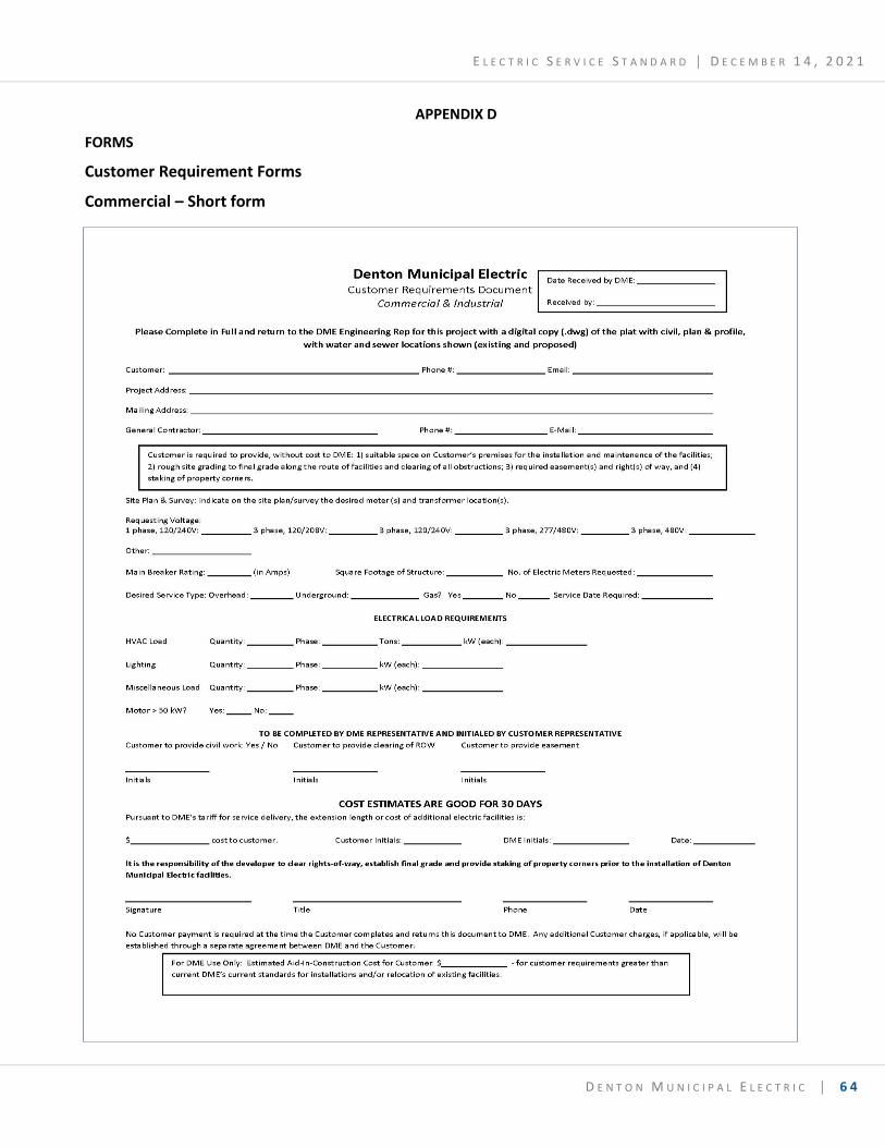
E L E C T R I C S E R V I C E S T A N D A R D │ D E C E M B E R 1 4 , 2 0 2 1
D E N T O N M U N I C I P A L E L E C T R I C │ 6 4
APPENDIX D
FORMS
Customer Requirement Forms
Commercial – Short form
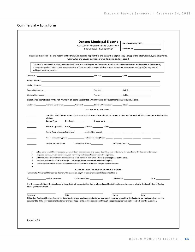
E L E C T R I C S E R V I C E S T A N D A R D │ D E C E M B E R 1 4 , 2 0 2 1
D E N T O N M U N I C I P A L E L E C T R I C │ 6 5
Commercial – Long form
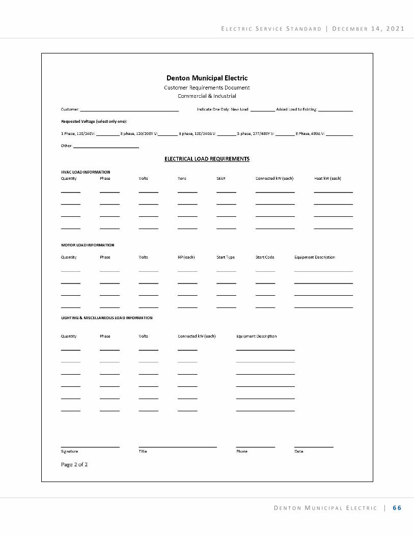
E L E C T R I C S E R V I C E S T A N D A R D │ D E C E M B E R 1 4 , 2 0 2 1
D E N T O N M U N I C I P A L E L E C T R I C │ 6 6
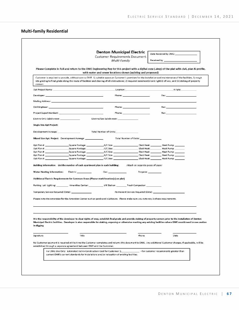
E L E C T R I C S E R V I C E S T A N D A R D │ D E C E M B E R 1 4 , 2 0 2 1
D E N T O N M U N I C I P A L E L E C T R I C │ 6 7
Multi-family Residential
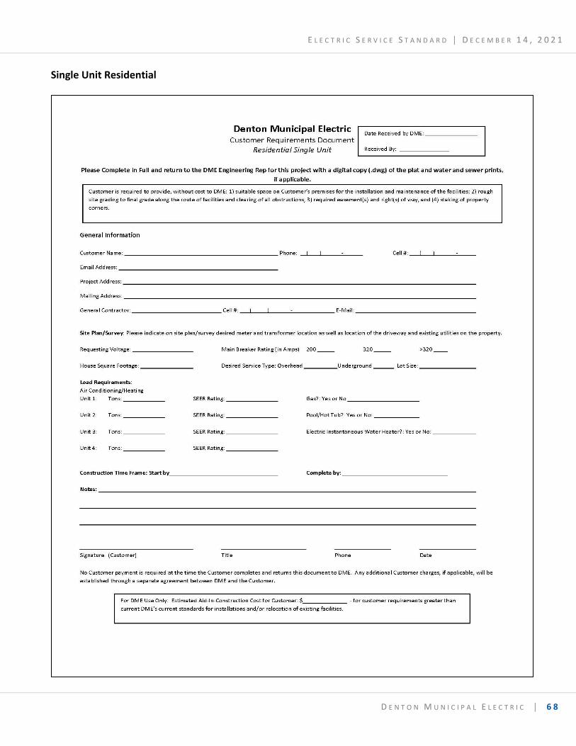
E L E C T R I C S E R V I C E S T A N D A R D │ D E C E M B E R 1 4 , 2 0 2 1
D E N T O N M U N I C I P A L E L E C T R I C │ 6 8
Single Unit Residential
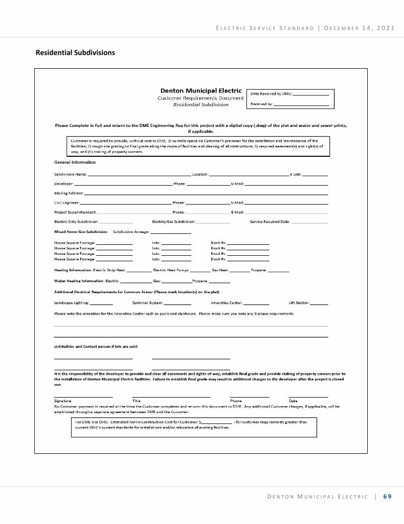
E L E C T R I C S E R V I C E S T A N D A R D │ D E C E M B E R 1 4 , 2 0 2 1
D E N T O N M U N I C I P A L E L E C T R I C │ 6 9
Residential Subdivisions
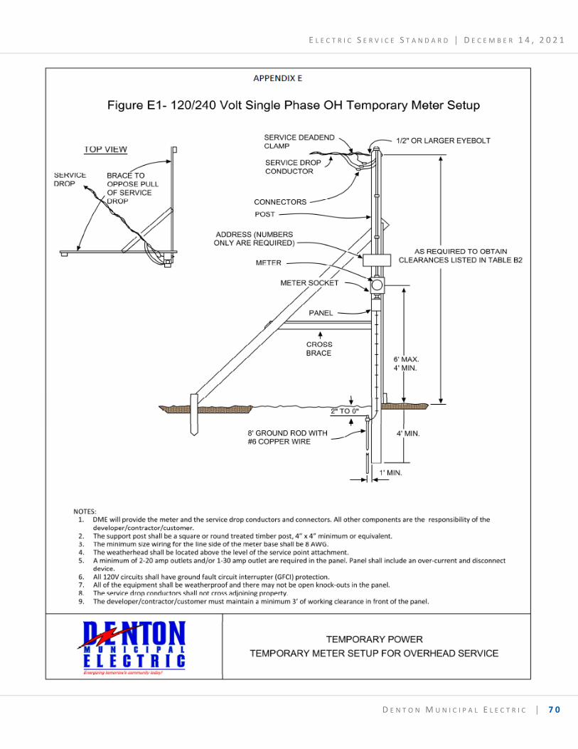
E L E C T R I C S E R V I C E S T A N D A R D │ D E C E M B E R 1 4 , 2 0 2 1
D E N T O N M U N I C I P A L E L E C T R I C │ 7 0
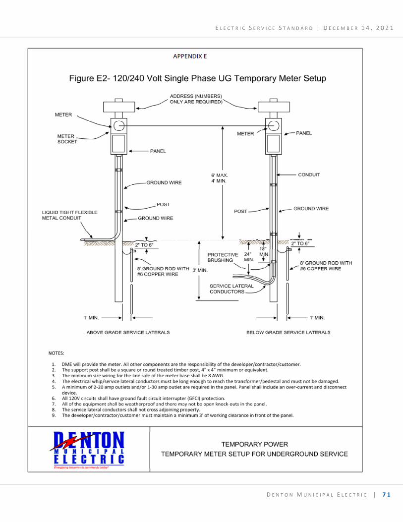
E L E C T R I C S E R V I C E S T A N D A R D │ D E C E M B E R 1 4 , 2 0 2 1
D E N T O N M U N I C I P A L E L E C T R I C │ 7 1