Embed Size (px)
Citation preview
Member Installation Standards
for Electric Service
June 2014 Edition This document is not copyrighted. Copying is encouraged.
Contents
Section 1: Foreword, General Information, and Terms .......................................................................................6
1.1 Purpose .......................................................................................................................................................... 6
1.2 Service Contracts, Terms and Conditions ...................................................................................................... 6
1.3 Service Standards Availability and Revisions ................................................................................................. 6
1.4 How to Interpret and Apply the Standards ................................................................................................... 7
1.5 General Terms Used in Service Standards ..................................................................................................... 7
1.6 Electrical Terms Used in Service Standards ................................................................................................. 10
Section 2: Safety, Member's Service Obligations, and Protection ...................................................................... 12
2.1 Safety ........................................................................................................................................................... 12
2.2 Code Requirements ..................................................................................................................................... 12
2.3 Distance Requirements for Member Structures ......................................................................................... 12
2.4 Working in Close Proximity to the Cooperative's Facilities ......................................................................... 12
2.5 OSHA Working Requirements ..................................................................................................................... 13
2.6 Lightning and Other Surge Protection ......................................................................................................... 13
2.7 Clearance to Buildings, Signs, and Other Installations ................................................................................ 13
2.8 Attachments to Cooperative Poles .............................................................................................................. 13
Section 3: How to Request Electric Service ....................................................................................................... 14
3.1 Application for Service................................................................................................................................. 14
3.2 Pre-Installation Information ........................................................................................................................ 14
3.3 Alterations to Existing Service ..................................................................................................................... 14
3.4 Required Information for New Service or Alteration to Service ................................................................. 15
3.5 Connection of Service .................................................................................................................................. 16
3.5.1 General Comments .............................................................................................................................. 16
3.5.2 Residential Self-Contained Meters ...................................................................................................... 16
3.5.3 Commercial and Industrial Self-Contained Meters and All Three-phase Services & Single-phase
CT-Rated Services ................................................................................................................................ 16
Section 4: Types of Service .............................................................................................................................. 17
4.1 General Characteristics................................................................................................................................ 17
4.2 Availability of Single-phase Service ............................................................................................................. 17
4.3 Availability of Three-phase Service ............................................................................................................. 17
4.4 Overhead or Underground Service.............................................................................................................. 17
4.5 Temporary Service ....................................................................................................................................... 18
4.6 Services for Individually Located Mobile Homes, RV’s, and Travel Trailers ................................................ 18
4.7 Services for Mobile Home Parks and RV Parks ............................................................................................ 18
4.8 Meter-On-Pole Locations ............................................................................................................................ 19
4.9 Apartment and Commercial Building Service .............................................................................................. 20
4.10 Service to Irrigation Wells and other Loads Requiring Outdoor-Mounted Control Equipment ................. 20
4.11 Service to Marinas and Boat Docks ............................................................................................................. 20
Section 5: Standard Service Voltage and Phase Configurations ......................................................................... 21
5.1 General Comments ...................................................................................................................................... 21
5.2 Available Standard Voltage and Phase Configurations ............................................................................... 21
This document is available at www.fecc.coop
FECC Member Installation Standards for Electric Service, June 2014 Page 2 of 86
5.3 Voltages for Heating .................................................................................................................................... 22
5.4 Voltages for Motors ..................................................................................................................................... 22
5.5 Voltages for Welders, Elevators, Hoists, Electronic Transmitters, X-Ray Machines, and Other
Miscellaneous or Special Equipment .......................................................................................................... 23
5.6 Voltages for Overhead or Underground Residential Areas Including Manufactured Homes, Mobile Home
Parks, Trailer Parks, and Individually Located Mobile Homes .................................................................... 23
Section 6: Service Requirements ...................................................................................................................... 24
6.1 General Comments ...................................................................................................................................... 24
6.2 Right-of-Way for Service Facilities ............................................................................................................... 25
6.3 Initial Clearing of Property for Right-of-Way ............................................................................................... 25
6.4 Relocation of Cooperative's Facilities .......................................................................................................... 25
Section 7: Permanent Overhead Service .......................................................................................................... 26
7.1 General Comments ...................................................................................................................................... 26
7.2 Point of Attachment on Home or Building .................................................................................................. 26
7.3 Clearances ................................................................................................................................................... 27
7.4 Length of Service Drop ................................................................................................................................ 27
7.5 Method of Attachment ................................................................................................................................ 27
7.6 Extension of Overhead Distribution Facilities ............................................................................................. 28
Section 8: Underground Service and Installations ............................................................................................. 29
8.1 General Comments ...................................................................................................................................... 29
8.2 Ownership of Facilities ................................................................................................................................ 29
8.3 Initial Clearing of Property for Underground Service .................................................................................. 29
8.4 Agreement for Underground Service .......................................................................................................... 29
8.5 Specification Requirements ......................................................................................................................... 30
8.6 Installations for Residential & Small Commercial Underground Service Rated Up To 320 Amps .............. 30
8.6.1 General Comments .............................................................................................................................. 30
8.6.2 Underground Electric Service for Residential Subdivisions and Commercial Developments ............. 30
8.6.3 Underground Service Rated up to 320 Amps from an Underground Distribution System. ................ 31
8.6.4 Underground Service Rated up to 320 Amps from Overhead Distribution System ............................ 31
8.6.5 Underground Service Replacing Existing Overhead Service ................................................................ 31
8.7 Installations for Large Commercial & Industrial Underground Service Rated Above 320 Amps ................ 31
8.7.1 General Comments .............................................................................................................................. 31
8.7.2 Junction Box Requirements ................................................................................................................. 31
8.7.3 Underground Service Rated Above 320A from Underground Systems .............................................. 32
8.7.4 Underground Service Rated Above 320A from Overhead Systems .................................................... 32
8.8 Underground Electric Service for Mobile Home Parks or RV Parks ............................................................ 33
8.9 Underground Service Conduit Systems ....................................................................................................... 33
8.9.1 General Comments .............................................................................................................................. 33
8.9.2 Installation ........................................................................................................................................... 33
8.10 Conductors .................................................................................................................................................. 34
8.10.1 General Comments .............................................................................................................................. 34
8.10.2 Conductors Used for Underground Service up to 320 Amps .............................................................. 34
8.10.3 Conductors Used for Underground Service Over 320 Amps ............................................................... 34
8.11 Termination of Members’ Conductors in Cooperative’s Transformers ...................................................... 35
8.12 Metering for Underground Service ............................................................................................................. 35
This document is available at www.fecc.coop
FECC Member Installation Standards for Electric Service, June 2014 Page 3 of 86
8.13 Transformers Used in Underground Installations ....................................................................................... 35
Section 9: Not used in this edition ............................................................................................................ 36
Section 10: Transformers................................................................................................................................. 37
10.1 General Comments ...................................................................................................................................... 37
10.2 Fences, Screen Walls, Decorative Walls ...................................................................................................... 37
10.3 Types of Transformer Installations .............................................................................................................. 37
10.4 Pad Mount Transformers ............................................................................................................................ 38
10.5 Termination of Secondary Conductors to Transformers for Services Rated Above 320 Amps .................. 38
Section 11: Metering Installations and Equipment ........................................................................................... 39
11.1 General Comments ...................................................................................................................................... 39
11.1.1 Responsible Parties.............................................................................................................................. 39
11.1.2 Meter Socket Specifications ................................................................................................................ 39
11.1.3 Current Transformer (CT) Enclosure Specifications ............................................................................ 40
11.2 Meter Connections and Seals ...................................................................................................................... 40
11.3 Meter Clearance .......................................................................................................................................... 40
11.4 Outdoor Meters ........................................................................................................................................... 41
11.5 Location of Meter Installations ................................................................................................................... 41
11.6 Multiple Meter Installations ........................................................................................................................ 41
11.7 Meter Mounting Height .............................................................................................................................. 42
11.8 Types of Meter Installations ........................................................................................................................ 42
11.8.1 Self-Contained Metering Installations ................................................................................................. 42
11.8.2 Current Transformer (CT) Installation ................................................................................................. 42
11.9 Primary Metering Installations .................................................................................................................... 43
11.10 Meter Grounding ......................................................................................................................................... 43
Section 12: Emergency, Standby, and Distributed Generation Systems ............................................................. 44
12.1 Electrical Emergency or Standby Systems ................................................................................................... 44
12.2 Distributed Generation Systems (DG) ......................................................................................................... 44
12.3 Use of Wind, Solar, or other Renewable Generation for Net Metering...................................................... 44
Section 13: Service Equipment Requirements .................................................................................................. 46
13.1 General Comments ...................................................................................................................................... 46
13.2 Inspection and Approvals ............................................................................................................................ 46
13.3 Meter Requirements ................................................................................................................................... 46
13.4 Service Entrance Conductors ....................................................................................................................... 47
13.5 Grounding of Service Equipment ................................................................................................................ 47
13.6 Service Entrance from Overhead System .................................................................................................... 48
13.6.1 General Comments .............................................................................................................................. 48
13.6.2 Service Entrance Masts ....................................................................................................................... 48
13.7 Service Entrance from Underground Distribution System .......................................................................... 48
13.8 Service Disconnecting Means ...................................................................................................................... 48
13.8.1 General Comments .............................................................................................................................. 48
13.8.2 Self-contained Meter Service Disconnects .......................................................................................... 49
Section 14: Member’s Equipment and Appliances ............................................................................................ 50
14.1 General Comments ...................................................................................................................................... 50
14.2 Radio and Television Interference ............................................................................................................... 50
14.3 Electric Heating ............................................................................................................................................ 50
This document is available at www.fecc.coop
FECC Member Installation Standards for Electric Service, June 2014 Page 4 of 86
14.4 Motors and HVAC Equipment - Voltage Rating ........................................................................................... 50
14.5 Motors and HVAC Equipment – Starting Current ........................................................................................ 51
14.5.1 General Comments .............................................................................................................................. 51
14.5.2 Single-phase Motors ............................................................................................................................ 51
14.5.3 Three-phase Motors ............................................................................................................................ 52
14.5.4 Motor Starting and Control Equipment............................................................................................... 52
14.6 Critical Service Motor Operation ................................................................................................................. 53
14.7 Motor and HVAC Equipment Protection ..................................................................................................... 53
14.7.1 Phase Reversal Protection ................................................................................................................... 53
14.7.2 Over-current Protection ...................................................................................................................... 53
14.7.3 Single-Phase Protection Required ....................................................................................................... 53
14.8 Phase Converters for Motor or HVAC Equipment Operation ..................................................................... 54
Section 15: Member’s Specialized Equipment .................................................................................................. 55
15.1 General Comments ...................................................................................................................................... 55
15.2 Additional Electric Facilities ......................................................................................................................... 55
15.3 Radio, Satellite, and Television Antennas ................................................................................................... 55
15.4 Electric Welders, Furnaces, and Industrial Equipment ............................................................................... 55
15.5 High-Power Electronic Equipment .............................................................................................................. 56
15.6 Member’s Capacitors and Other Reactive Power Equipment..................................................................... 56
Section 16: Power Quality Standards ............................................................................................................... 57
16.1 General Comments ...................................................................................................................................... 57
16.2 Steady State Voltage to Member ................................................................................................................ 57
16.3 Voltage Unbalance ...................................................................................................................................... 58
16.3.1 Voltage Unbalance at Service Entrance ............................................................................................... 58
16.3.2 Single-phasing ...................................................................................................................................... 58
Section 17: Specification Drawings .................................................................................................................. 59
This document is available at www.fecc.coop
FECC Member Installation Standards for Electric Service, June 2014 Page 5 of 86
Section 1: Foreword, General Information, and Terms
1.1 Purpose
The information contained in this document is presented for use by First Electric Cooperative members, builders, contractors, and engineers in planning and constructing electrical service installations to be served by the Cooperative. These procedures, practices, and requirements are intended to assure economical and satisfactory service to the Cooperative’s members, consistent with the most recent versions of the National Electrical Safety Code (NESC) and the National Electrical Code (NEC). Any mention of the NESC or the NEC indicates the basic provisions that are considered necessary for safety. In the event that the Cooperative's standards are more stringent than provisions of the NESC or NEC, the Cooperative's standards shall be followed. The member or the member’s representative is encouraged to contact the Cooperative before any planning or construction takes place.
This document presents the Cooperative’s requirements only, and is not intended to be a comprehensive guide for the installation of an electrical service. To ensure a safe, quality installation that complies with the NEC and local code requirements, the Cooperative recommends that all work be done by a qualified, licensed electrical contractor.
1.2 Service Contracts, Terms and Conditions
The following documents are not included in these Service Standards:
(1) Policy Schedules, which prescribe the rules, obligations, and liabilities of the Cooperative in providing service and the member in receiving electric service;
(2) Rate Schedules, which set forth the price, periods of taking, and payment terms for electric service;
(3) Service Agreements wherein the member and the Cooperative agree to specific quantities and type of service.
The Cooperative’s currently approved Service Regulations, Rate Schedules, Service Agreements, and other forms are available by contacting the Cooperative. The member should contact the Cooperative early in the design phase of a project for information concerning the terms and conditions of service.
1.3 Service Standards Availability and Revisions
These Service Standards are available at the Cooperative’s offices, and are available for viewing and download on the Cooperative’s website at www.firstelectric.coop. These Service Standards may be revised from time to time as needed, and new editions will be posted to the Cooperative’s website. Revisions to the Standards will go into effect when approved by Cooperative Management. It is the member’s responsibility to make sure that the latest Standards are followed for construction of electric service. Contact the Cooperative or go to our website to determine if the Standards you possess are the latest edition.
This document is available at www.fecc.coop
FECC Member Installation Standards for Electric Service, June 2014 Page 6 of 86
1.4 How to Interpret and Apply the Standards
When reading the Service Standards, note the following key words:
Shall: Any rule using the word “shall” is strictly enforced.
Must: Same meaning as “shall”.
Should: Any rule using “should” carries the idea that options exist, but that the rule follows the best engineering advice as written. This rule could be less strictly enforced than the “shall” rule.
Recommend: Any rule using “recommend” has several options, but the Cooperative would like the member to use the one given. “Recommend” is never used where safety is an issue.
May: Any rule using “may” is allowed by the Cooperative, at the member’s option.
1.5 General Terms Used in Service Standards
Application (or Agreement for Service or Contract): The agreement between the Cooperative and the member under which service is taken. Until a written agreement for service has been signed, service rendered by the Cooperative is subject to the provisions of the Cooperative's Service Regulations and applicable rate schedule. The provisions of the Cooperative's standard application for service will be presumed to apply. The supplying and taking of such service shall constitute an Agreement for Service.
Authorities (having jurisdiction) (AHJ): The organization, office, or individual responsible for approving equipment, materials, an installation, or a procedure. The basic role of an AHJ is to verify that an installation complies with the National Electric Code.
Cooperative: First Electric Corporation, its operating subsidiaries, officers, agents or employees.
Cooperative Designated Underground Areas: Those portions of the Cooperative's service area, defined by the Cooperative, where overhead service is not available. This includes many residential subdivisions, and areas of concentrations of commercial buildings with large loads that are not practical to serve with overhead facilities.
Cooperative's Installation: In general, all the wires, devices, or apparatus on the Cooperative's side of the point of delivery. Some equipment, such as devices installed for metering electric consumption or for demand side management, may belong to the Cooperative, yet be installed on member's side of the point of delivery.
Cooperative Pole: Includes Cooperative-owned poles, and poles occupied by the Cooperative under joint use agreements.
Cooperative Specifications: The particular details developed by the Cooperative as its standard, which may include specifications of manufacturers and regulatory bodies having jurisdiction.
Conduit: Electrical-grade conduit as defined in the National Electrical Code: EMT – Electrical Metallic Tubing; IMC – Intermediate Metal Conduit; RMC – Rigid Metallic Conduit; PVC – Rigid Schedule 40 or Schedule 80 Polyvinyl Chloride Conduit.
Conduit System: Any combination of duct, conduit, conduits, manholes, handholds, and vaults joined to form an integrated whole.
Contract: See "Application".
This document is available at www.fecc.coop
FECC Member Installation Standards for Electric Service, June 2014 Page 7 of 86
Demand: The kW or kVA, as shown or computed from the readings of the Cooperative's demand meter installation, for the interval of the member's greatest use between readings. (This is also known as maximum demand.)
Disconnect: An approved switching device that enables the disconnection of the electric service from the supply conductors or equipment.
Easement: An interest in land owned by another that entitles its holder to a specific limited use. (The Cooperative’s right-of-way is an easement.)
Electric Service: See "Service".
Emergency Service: An additional, separate service, when required by regulatory authorities, for exit or emergency lighting, fire pumps, or to satisfy other safety regulations.
Inaccessible Area: Any area, as designated by Cooperative, which would be difficult to enter for the purpose of conducting normal or emergency operations or maintenance.
Load: The amount of electric power delivered or required at any specified point or points on a system.
Line Extension: Any new construction, or improvement of existing facilities, that is required to connect the Cooperative’s existing overhead or underground system to the member’s service equipment. In some cases, the member may be required to make a contribution toward the cost of a line extension. Any required contribution will be discussed with the member prior to constructing the service. Line extension rules are contained in Part III, Section 70 of the Cooperative’s tariffs as approved by the Arkansas Public Service Commission.
Member: An individual, firm, partnership, association, corporation, organization, or governmental agency who is a member of the Cooperative and taking service as defined by Cooperative’s Bylaws and regulatory authorities.
Member's Installation: In general, all the wires, appliances, devices or apparatus of any kind or character on the member's side of the point of delivery except the meters, metering devices and facilities of the Cooperative that may be located on the member's side of the point of delivery. The member's wiring and electrical equipment within or on the premises shall be installed and maintained in accordance with all effective building and wiring codes, and local laws and ordinances.
Meter: A device or devices together with auxiliary equipment used for measuring any of the following: apparent, real, and reactive power and/or energy, which are supplied to any member at a single point of delivery.
Mobile or Manufactured Home: A structure, transportable in one or more sections, that, in the traveling mode, is 8 feet or more in width and 40 feet or more in length, or is more than 400 square feet when erected on site, and is designed and constructed to the Federal Manufactured Construction and Safety Standards, and is so labeled. To qualify as a permanent service, the home shall be tied down on a permanent foundation, and shall be permanently connected to a community sewer system or a septic system meeting the Arkansas Department of Health standards, and to a public water system or water well.
NEC (National Electrical Code): The electrical safety code published by the National Fire Protection Association, Inc. (NFPA) for the practical safeguarding of persons and property from hazards arising from the use of electricity. The NEC is adopted by the State of Arkansas as a statewide standard for the construction, installation, and maintenance of electrical facilities for farms, homes, offices, factories, and all other public or private buildings or electrical installations.
This document is available at www.fecc.coop
FECC Member Installation Standards for Electric Service, June 2014 Page 8 of 86
NESC (National Electrical Safety Code): The code published by the Institute of Electrical and Electronics Engineers Inc. (IEEE) for the practical safeguarding of persons, utility facilities, and affected property during the installation, and operation, and maintenance of electric supply and communication facilities, under specified conditions. The NESC is adopted by the State of Arkansas as a statewide standard for all public electric utilities and cooperatives.
Point of Delivery: (also called Service Point) the physical location where the member's service terminals or wires are joined to the Cooperative's facilities or such other point specifically designated by written agreement. For most residential services the point of delivery is the line-side of the meter location.
Public Property: Property dedicated to public use such as streets, alleys, canals, roadways, and highways. This does not include schools, parks, public housing, gyms, playgrounds, public buildings, etc., which are considered member premises.
Recreational Vehicle: A vehicular unit designed as temporary living quarters for recreational, camping, or travel use, which either has its own motive power or is drawn by another vehicle. Recreational vehicles include travel trailers (see definition), camping trailers, truck campers, and motor homes. RV’s are not considered permanent services for line extension purposes.
Rigid Metal Conduit: A raceway specially constructed for the purpose of the pulling in or the withdrawing of wire or cable after the conduit is in place and made of metal pipe of standard weight and thickness permitting the cutting of standard threads.
Rigid Non-metallic Conduit: Gray polyvinyl chloride (PVC), schedule 80 or schedule 40, tube for enclosure of electrical wires and cables which includes associated equipment such as adapters, cable enclosures, couplings, junction boxes, pull boxes, etc., as required for a complete enclosure system. (Schedule 80 PVC shall be manufactured per NEMA TC-2 standard.)
Service (or Electric Service): The availability of electric power and energy to the member, regardless of whether any power and energy is actually used. Supplying of service by the Cooperative consists of its maintaining at the point of delivery the approximate nominal voltage and frequency by means of facilities adequate for supplying the member's contracted load.
Service Conductors: The underground supply conductors that extend from the Cooperative’s pedestal or transformers to the service equipment of the premises supplied. The Cooperative normally provides and installs the service conductors for services rated up to 320A. The member provides and installs the service conductors for services rated above 320A, and the Cooperative makes the connections at its pedestal or transformer.
Service Drop Conductors: The overhead service conductors from the Cooperative’s pole or other aerial support to and including the splices, if any, connecting to the service-entrance conductors at the building or other structure. The Cooperative normally provides and installs the service drop conductors and splices for services rated up to 320A. The member provides and installs the service drop conductors for services rated above 320A, and the Cooperative makes the service drop attachment and connections at its pole.
Service Entrance: The member-owned equipment for connecting to the service conductors or the service entrance conductors.
This document is available at www.fecc.coop
FECC Member Installation Standards for Electric Service, June 2014 Page 9 of 86
Service Entrance Conductors:
1. Overhead System: The service conductors between the terminals of the service equipment and a point usually outside the building, clear of building walls, where it is joined by tap or splice to the service drop.
2. Underground System: The service conductors between the terminals of the service equipment and the point of connection to the service lateral.
Service Lateral Conductors: The underground conductors from the Cooperative’s supply source to the member’s service point.
Service Point: The point of connection between the Cooperative’s facilities and the member’s premises wiring. Also called the Point of Delivery.
Travel Trailer: A vehicular unit, mounted on wheels, designed to provide temporary living quarters for recreational, camping, vacation, or travel use, up to 8 feet in width and 40 feet in length when in traveling mode, and has a floor area of not more than 400 square feet. This definition also includes Park Trailers. Travel trailers and park trailers are not considered permanent services for line extension purposes.
Type of Service: The electrical or physical attributes of the service, such as voltage, phase, frequency, transformer connection, number of wires, overhead or underground installation, etc.
Underground Service: The underground cable installation that connects the Cooperative's distribution system to the member's service entrance conductors, or to the supply side lugs of the meter socket.
UL (Underwriters Laboratories) is an internationally recognized safety consulting and certification company. UL provides safety-related certification, validation, testing, inspection, auditing, advising and training services to a wide range of clients, including manufacturers, retailers, policymakers, regulators, service companies, and consumers.
1.6 Electrical Terms Used in Service Standards
Ampere: A unit of measurement of electric current (abbreviated A or amp).
Btu (British Thermal Unit): The quantity of heat required to raise the temperature of one pound of water one degree Fahrenheit. Capacity of air conditioning, heating, or heat content of fuel, etc. is measured in Btu. Btu per hour is the rate of heat change (Btu/h).
Current: The flow of electricity usually measured in amperes.
Energy: The total work done as distinguished from the rate of doing work (power), usually measured in kilowatt-hours (kWh). Its amount depends upon the power and the time that the power is taken. For instance, a 100 watt light bulb burned for one hour uses 100 watt-hours of energy; if burned for 10 hours the bulb uses 1000 watt-hours, or 1 kilowatt-hour of energy.
Hertz: Unit of alternating current frequency in cycles per second (abbreviated Hz). The U.S. electric system furnishes 60 Hz alternating current.
Horsepower: A unit of mechanical power, equal to a rate of lifting 550 pounds one foot in one second (abbreviated hp). Motors are normally rated in horsepower to indicate the mechanical power they are designed to produce.
This document is available at www.fecc.coop
FECC Member Installation Standards for Electric Service, June 2014 Page 10 of 86

Kilovolt-ampere (kVA): 1,000 volt amperes, the unit of apparent power, volts multiplied by amperes, which is comprised of both real and reactive power.
Kilowatt: (kW) 1,000 watts.
Kilowatt-hour: (kWh) A quantity of electrical energy – equal to 1000 watts used continuously for one hour, or 100 watts used continuously for 10 hours, or some other equivalent.
Number of Phases: See "Phase".
Ohm: The unit of measurement of electrical resistance or impedance. It is that resistance through which one volt will produce a current of one ampere.
Phase (or Number of Phases): Term that designates characteristics of alternating current. It is a term used in the electric industry relating to the characteristics of the electrical service available or supplied at a given location or required for the operation of a given electrical device. Single-phase is normally supplied for residences and small power members, and three-phase is supplied for members with higher power requirements.
Power: The time rate of doing work, generating, transferring, or using electric energy, commonly expressed in kilowatts (kW).
Power Factor: The ratio of real power (kW) to apparent power (kVA) for any given load and time. Normally, power factor is expressed as a ratio and stated as a percentage. When the power factor is less than 100%, the power system is not operating efficiently. For this reason, capacitors or other power factor correction equipment must be used to correct the power factor to as near 100% as practicable.
Power Quality: A set of voltage limits that allows electrical systems and equipment to function in their intended manner without significant loss of performance or life. Without the proper voltage quality, an electrical device (or load) may malfunction, fail prematurely, or not operate at all.
Sag (Voltage sag): A decrease in RMS voltage at the power frequency for duration of 0.5 cycles to 1 minute. Typical values are 0.1 to 0.9 per unit.
Volt / Voltage: A unit of electrical pressure or potential or electromotive force that if applied to a load of one ohm resistance will cause a current of one ampere to flow. Primary distribution and transmission voltages are usually designated in kilovolts (kV). One kilovolt is equal to 1,000 volts.
Watt: An electrical unit of power. Electrical appliances and lamps are rated in watts to indicate their capacity or rate of using power for doing work. A 100 watt lamp used 10 hours will use one kilowatt-hour (kWh) of energy (1,000 watt-hours). Likewise a household iron rated at 1,000 watts will use one kilowatt-hour in one hour.
This document is available at www.fecc.coop
FECC Member Installation Standards for Electric Service, June 2014 Page 11 of 86
Section 2: Safety, Member's Service Obligations, and Protection
2.1 Safety
Safety is paramount. If the Cooperative believes, based upon observation, information or experience that danger to the public or to an individual exists, work shall stop and service may be disconnected until such danger is remedied.
2.2 Code Requirements
The data contained herein is intended to conform with and be supplementary to recognized codes or rules and regulations of the authority having jurisdiction over the installation. In all cases, those codes or rules and regulations shall govern, regardless of possible conflict in the expressed or implied meaning of the contents of this document. The contents are intended to be consistent with the principles of the NEC on the member's side of service and generally consistent with the NESC on the Cooperative side. Compliance with the minimum requirements of the NEC will provide the member with what is considered a minimum standard for appropriate use of electricity. Any difference from the NEC is intended to provide better service than required by the standards of the NEC.
2.3 Distance Requirements for Member Structures
The construction of any structure near, under or over electrical facilities may cause a code and / or safety violation and be an encroachment on Cooperative-right-of-way. Consult the Cooperative concerning all clearances. Permanent or temporary structures shall never be located within 10 feet (measured horizontally) of the Cooperative’s aboveground electrical facilities. The Cooperative will not allow the placement of electrical service nearby, over, or under a pool, nor permit the construction of a pool nearby, over, or under electrical facilities - see Drawings 7.2-1 (Overhead) and 8.6-4 (Underground) and consult the Cooperative.
2.4 Working in Close Proximity to the Cooperative's Facilities
Members should use extreme caution to avoid contact when working in the proximity of the Cooperative's overhead or underground conductors or other electric facilities to prevent injury and to prevent damage to either the Cooperative's or the member's equipment. Arkansas state law (High Voltage Act, Title 11, Chapter 5, Subchapter 3 of the AR State Code) prohibits unauthorized persons from working, including moving tools or equipment, within 10 feet of any high voltage overhead electric utility line. If any unauthorized person intends to work within 10 feet of any high voltage overhead line, the person responsible for the work to be done must notify the owner or operator of the high voltage overhead electric utility line not less than 48 hours prior to commencing work. Please note transmission level voltage requires greater clearance.
Work shall be performed only after satisfactory mutual arrangements have been completed between the owner or operator of the high voltage overhead electric utility line and the person responsible for the work to be done. To notify the Cooperative that you intend to work within 10 feet of a high voltage overhead electric utility line owned or operated by it, please call 1-800-489-7405 not less than two business days prior to commencing work.
The Cooperative shall be consulted for location of the Cooperative's conductors and electrical facilities before operating equipment near the Cooperative’s facilities. In locations where excavation is planned, the member shall notify ONECALL by dialing 811 not less than 48 hours prior to commencing work and
This document is available at www.fecc.coop
FECC Member Installation Standards for Electric Service, June 2014 Page 12 of 86
shall have ONECALL locate all underground facilities before digging. It shall be the responsibility of the member to stay clear of all electric facilities.
2.5 OSHA Working Requirements
OSHA (Title 29 of the Code of Federal Regulations, Section 1926.550 (a) (15)) requires that all operators of equipment maintain a minimum of 10 feet of radial clearance from energized electrical facilities. Please note transmission level voltage requires greater clearance.
2.6 Lightning and Other Surge Protection
Surge arrester protection by the member is not required for services under 480 Volts. With the proliferation of electronic home entertainment equipment and appliances, however, the Cooperative suggests that the member consider installing surge protection. It shall be installed on the load side of the meter, and shall not be connected to the service drop conductors or to the service entrance conductors. The surge protection should be installed as closely as possible to the device to be protected. Members with services above 480 Volts should install surge arrestors. Consult the NEC Article 280, a licensed, professional engineer, or the manufacturer of protective equipment.
2.7 Clearance to Buildings, Signs, and Other Installations
Clearances of buildings, signs, and other structures to the Cooperative’s facilities shall meet or exceed the clearance requirements set forth in the National Electrical Safety Code Article 234. The member shall be responsible for the cost of relocating lines or structures, or otherwise correcting any violations caused by the member’s actions.
2.8 Attachments to Cooperative Poles
The Cooperative will provide, install, and maintain meter poles as required. Other than the member’s service equipment, no other attachments (i.e. member-owned lighting, control equipment, antennas, basketball goals, bird houses, etc.) may be made to the meter pole. Attachments to any other Cooperative poles are normally not allowed. Attachments may be made only with approval of the Cooperative. Unauthorized attachments may be removed upon discovery. If an attachment is allowed, an attachment agreement shall be signed, and the agreement will set forth any charges. All permitted attachments are to be made under the supervision and to the satisfaction of the Cooperative. All allowed attachments shall be made in accordance with the specifications of authorities having jurisdiction, where applicable. Consult the Cooperative for details.
This document is available at www.fecc.coop
FECC Member Installation Standards for Electric Service, June 2014 Page 13 of 86
Section 3: How to Request Electric Service
3.1 Application for Service
A member may apply for service by contacting the Cooperative by phone at 1-800-489-7405. Service rendered by the Cooperative is subject to the provisions of the Cooperative's Bylaws, Service Regulations, and applicable rate schedule. The supplying and taking of such service shall constitute an Agreement for Service if no written agreement for service or application for service has been executed.
3.2 Pre-Installation Information
The Cooperative can expedite service connection and minimize cost to both the member and the Cooperative if the member consults the Cooperative before the design phase of the installation has begun. Architects, builders, contractors, developers, engineers, electricians, or property owners are urged to consult the Cooperative for information regarding the availability and type of service, and location of the service drop, service entrance, and meter. The Cooperative is not responsible for the cost of replacing any of the member’s facilities that do not meet the requirements for service. Connection to the Cooperative's electric system is not available prior to approval by the Cooperative. The approval process may include the acquisition of permits and/or inspections by the authorities having jurisdiction.
3.3 Alterations to Existing Service
The Cooperative's facilities, including meters, transformers, and other equipment, are sized and installed by the Cooperative to satisfy the member's requirements at the time the service is initiated and is based on information supplied by the member. Consulting with the Cooperative regarding any change in the member’s requirements is recommended. It is essential that the member give notice to the Cooperative of any substantial additional load (e.g., a large motor) that is to be connected to the electric system. The member should not proceed to make these additions until after the Cooperative has notified them that it can either supply the increased load or the conditions under which the increased load can be served. The Cooperative is not liable for any damages incurred by the member connecting additional equipment without notice to the Cooperative. Under no circumstances shall any service drop wire, meter or metering equipment belonging to the Cooperative be disconnected, removed, or relocated unless authorized by the Cooperative (see also Section 11.2). This authorization requires advance notification. The Cooperative may require the replacement of the member's obsolete equipment at the service entrance or relocation of the service entrance to a more accessible area prior to providing the requested service.
The construction of pools, decks, fences or any structure near, under or over electrical facilities may cause a code and / or safety violation and be an encroachment on the Cooperative’s right-of-way. Consult the Cooperative concerning all clearances.
This document is available at www.fecc.coop
FECC Member Installation Standards for Electric Service, June 2014 Page 14 of 86
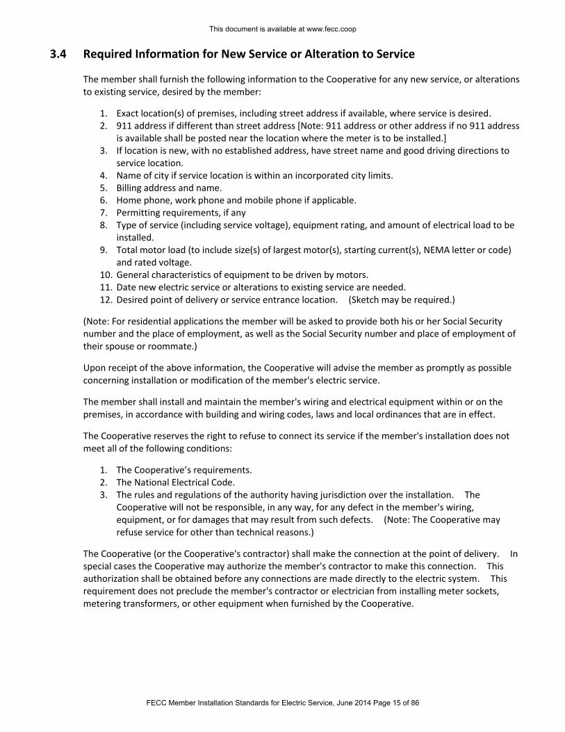
3.4 Required Information for New Service or Alteration to Service
The member shall furnish the following information to the Cooperative for any new service, or alterations to existing service, desired by the member:
1. Exact location(s) of premises, including street address if available, where service is desired. 2. 911 address if different than street address [Note: 911 address or other address if no 911 address
is available shall be posted near the location where the meter is to be installed.] 3. If location is new, with no established address, have street name and good driving directions to
service location. 4. Name of city if service location is within an incorporated city limits. 5. Billing address and name. 6. Home phone, work phone and mobile phone if applicable. 7. Permitting requirements, if any 8. Type of service (including service voltage), equipment rating, and amount of electrical load to be
installed. 9. Total motor load (to include size(s) of largest motor(s), starting current(s), NEMA letter or code)
and rated voltage. 10. General characteristics of equipment to be driven by motors. 11. Date new electric service or alterations to existing service are needed. 12. Desired point of delivery or service entrance location. (Sketch may be required.)
(Note: For residential applications the member will be asked to provide both his or her Social Security number and the place of employment, as well as the Social Security number and place of employment of their spouse or roommate.)
Upon receipt of the above information, the Cooperative will advise the member as promptly as possible concerning installation or modification of the member's electric service.
The member shall install and maintain the member's wiring and electrical equipment within or on the premises, in accordance with building and wiring codes, laws and local ordinances that are in effect.
The Cooperative reserves the right to refuse to connect its service if the member's installation does not meet all of the following conditions:
1. The Cooperative’s requirements. 2. The National Electrical Code. 3. The rules and regulations of the authority having jurisdiction over the installation. The
Cooperative will not be responsible, in any way, for any defect in the member's wiring, equipment, or for damages that may result from such defects. (Note: The Cooperative may refuse service for other than technical reasons.)
The Cooperative (or the Cooperative's contractor) shall make the connection at the point of delivery. In special cases the Cooperative may authorize the member's contractor to make this connection. This authorization shall be obtained before any connections are made directly to the electric system. This requirement does not preclude the member's contractor or electrician from installing meter sockets, metering transformers, or other equipment when furnished by the Cooperative.
This document is available at www.fecc.coop
FECC Member Installation Standards for Electric Service, June 2014 Page 15 of 86
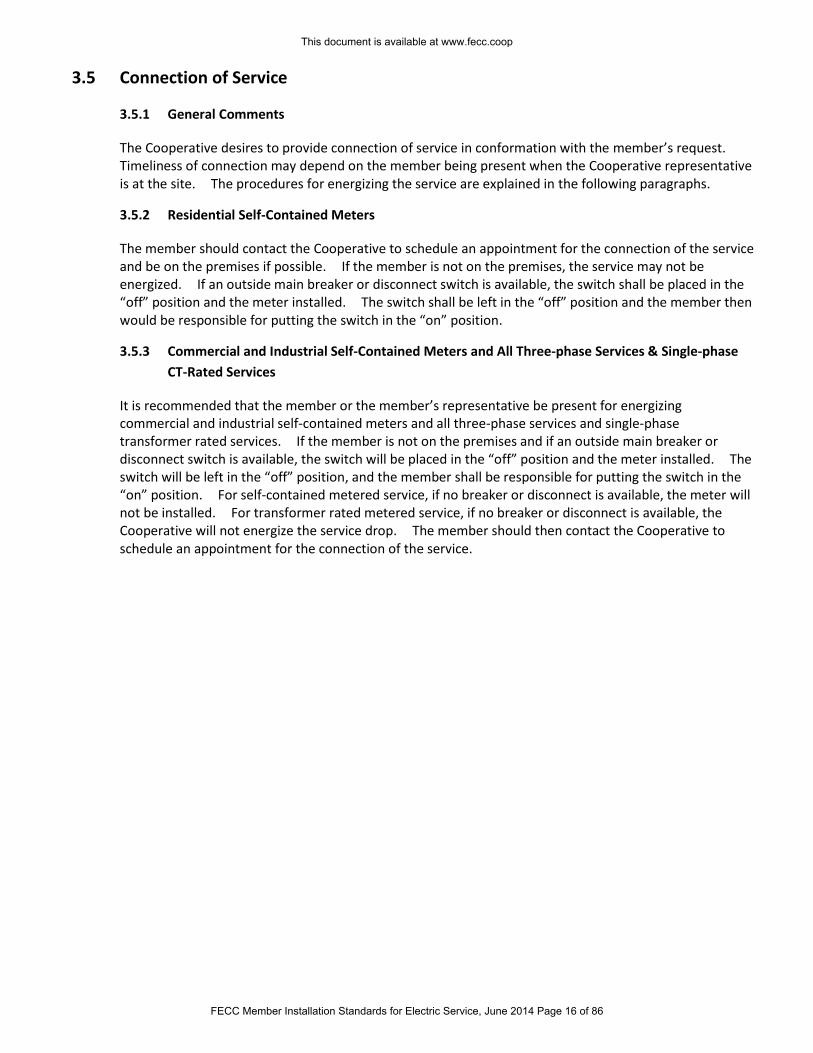
3.5 Connection of Service
3.5.1 General Comments
The Cooperative desires to provide connection of service in conformation with the member’s request. Timeliness of connection may depend on the member being present when the Cooperative representative is at the site. The procedures for energizing the service are explained in the following paragraphs.
3.5.2 Residential Self-Contained Meters
The member should contact the Cooperative to schedule an appointment for the connection of the service and be on the premises if possible. If the member is not on the premises, the service may not be energized. If an outside main breaker or disconnect switch is available, the switch shall be placed in the “off” position and the meter installed. The switch shall be left in the “off” position and the member then would be responsible for putting the switch in the “on” position.
3.5.3 Commercial and Industrial Self-Contained Meters and All Three-phase Services & Single-phase
CT-Rated Services
It is recommended that the member or the member’s representative be present for energizing commercial and industrial self-contained meters and all three-phase services and single-phase transformer rated services. If the member is not on the premises and if an outside main breaker or disconnect switch is available, the switch will be placed in the “off” position and the meter installed. The switch will be left in the “off” position, and the member shall be responsible for putting the switch in the “on” position. For self-contained metered service, if no breaker or disconnect is available, the meter will not be installed. For transformer rated metered service, if no breaker or disconnect is available, the Cooperative will not energize the service drop. The member should then contact the Cooperative to schedule an appointment for the connection of the service.
This document is available at www.fecc.coop
FECC Member Installation Standards for Electric Service, June 2014 Page 16 of 86
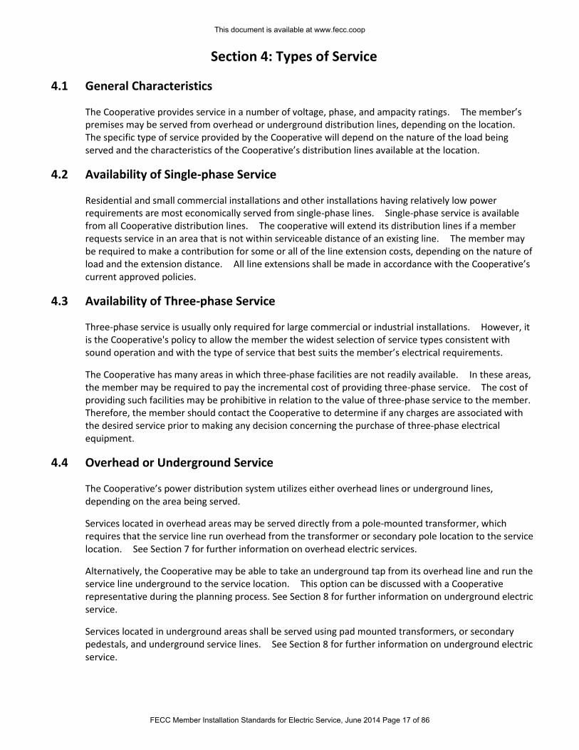
Section 4: Types of Service
4.1 General Characteristics
The Cooperative provides service in a number of voltage, phase, and ampacity ratings. The member’s premises may be served from overhead or underground distribution lines, depending on the location. The specific type of service provided by the Cooperative will depend on the nature of the load being served and the characteristics of the Cooperative’s distribution lines available at the location.
4.2 Availability of Single-phase Service
Residential and small commercial installations and other installations having relatively low power requirements are most economically served from single-phase lines. Single-phase service is available from all Cooperative distribution lines. The cooperative will extend its distribution lines if a member requests service in an area that is not within serviceable distance of an existing line. The member may be required to make a contribution for some or all of the line extension costs, depending on the nature of load and the extension distance. All line extensions shall be made in accordance with the Cooperative’s current approved policies.
4.3 Availability of Three-phase Service
Three-phase service is usually only required for large commercial or industrial installations. However, it is the Cooperative's policy to allow the member the widest selection of service types consistent with sound operation and with the type of service that best suits the member’s electrical requirements.
The Cooperative has many areas in which three-phase facilities are not readily available. In these areas, the member may be required to pay the incremental cost of providing three-phase service. The cost of providing such facilities may be prohibitive in relation to the value of three-phase service to the member. Therefore, the member should contact the Cooperative to determine if any charges are associated with the desired service prior to making any decision concerning the purchase of three-phase electrical equipment.
4.4 Overhead or Underground Service
The Cooperative’s power distribution system utilizes either overhead lines or underground lines, depending on the area being served.
Services located in overhead areas may be served directly from a pole-mounted transformer, which requires that the service line run overhead from the transformer or secondary pole location to the service location. See Section 7 for further information on overhead electric services.
Alternatively, the Cooperative may be able to take an underground tap from its overhead line and run the service line underground to the service location. This option can be discussed with a Cooperative representative during the planning process. See Section 8 for further information on underground electric service.
Services located in underground areas shall be served using pad mounted transformers, or secondary pedestals, and underground service lines. See Section 8 for further information on underground electric service.
This document is available at www.fecc.coop
FECC Member Installation Standards for Electric Service, June 2014 Page 17 of 86
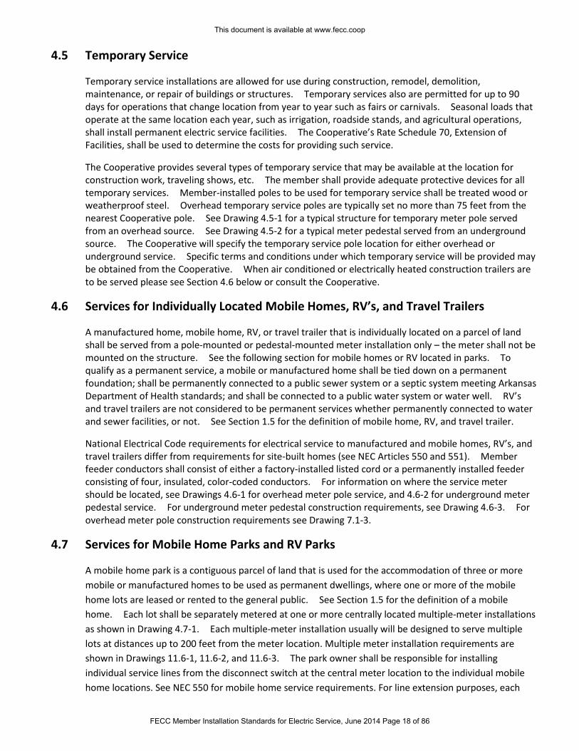
4.5 Temporary Service
Temporary service installations are allowed for use during construction, remodel, demolition, maintenance, or repair of buildings or structures. Temporary services also are permitted for up to 90 days for operations that change location from year to year such as fairs or carnivals. Seasonal loads that operate at the same location each year, such as irrigation, roadside stands, and agricultural operations, shall install permanent electric service facilities. The Cooperative’s Rate Schedule 70, Extension of Facilities, shall be used to determine the costs for providing such service.
The Cooperative provides several types of temporary service that may be available at the location for construction work, traveling shows, etc. The member shall provide adequate protective devices for all temporary services. Member-installed poles to be used for temporary service shall be treated wood or weatherproof steel. Overhead temporary service poles are typically set no more than 75 feet from the nearest Cooperative pole. See Drawing 4.5-1 for a typical structure for temporary meter pole served from an overhead source. See Drawing 4.5-2 for a typical meter pedestal served from an underground source. The Cooperative will specify the temporary service pole location for either overhead or underground service. Specific terms and conditions under which temporary service will be provided may be obtained from the Cooperative. When air conditioned or electrically heated construction trailers are to be served please see Section 4.6 below or consult the Cooperative.
4.6 Services for Individually Located Mobile Homes, RV’s, and Travel Trailers
A manufactured home, mobile home, RV, or travel trailer that is individually located on a parcel of land shall be served from a pole-mounted or pedestal-mounted meter installation only – the meter shall not be mounted on the structure. See the following section for mobile homes or RV located in parks. To qualify as a permanent service, a mobile or manufactured home shall be tied down on a permanent foundation; shall be permanently connected to a public sewer system or a septic system meeting Arkansas Department of Health standards; and shall be connected to a public water system or water well. RV’s and travel trailers are not considered to be permanent services whether permanently connected to water and sewer facilities, or not. See Section 1.5 for the definition of mobile home, RV, and travel trailer.
National Electrical Code requirements for electrical service to manufactured and mobile homes, RV’s, and travel trailers differ from requirements for site-built homes (see NEC Articles 550 and 551). Member feeder conductors shall consist of either a factory-installed listed cord or a permanently installed feeder consisting of four, insulated, color-coded conductors. For information on where the service meter should be located, see Drawings 4.6-1 for overhead meter pole service, and 4.6-2 for underground meter pedestal service. For underground meter pedestal construction requirements, see Drawing 4.6-3. For overhead meter pole construction requirements see Drawing 7.1-3.
4.7 Services for Mobile Home Parks and RV Parks
A mobile home park is a contiguous parcel of land that is used for the accommodation of three or more
mobile or manufactured homes to be used as permanent dwellings, where one or more of the mobile
home lots are leased or rented to the general public. See Section 1.5 for the definition of a mobile
home. Each lot shall be separately metered at one or more centrally located multiple-meter installations
as shown in Drawing 4.7-1. Each multiple-meter installation usually will be designed to serve multiple
lots at distances up to 200 feet from the meter location. Multiple meter installation requirements are
shown in Drawings 11.6-1, 11.6-2, and 11.6-3. The park owner shall be responsible for installing
individual service lines from the disconnect switch at the central meter location to the individual mobile
home locations. See NEC 550 for mobile home service requirements. For line extension purposes, each
This document is available at www.fecc.coop
FECC Member Installation Standards for Electric Service, June 2014 Page 18 of 86
mobile home park shall be classified as one service location regardless of the number of meters within the
park. To qualify as a permanent service, a mobile home park shall have graded, all-weather drives or
roadways to each lot; leveled pads to accommodate foundations and tie-downs for the home; and have a
park-approval letter from the Arkansas Department of Health.
An RV park is defined as a contiguous parcel of land for the accommodation of three or more RV parking
spaces. See Section 1.5 for the definition of a recreational vehicle or travel trailer. RV parking spaces are
usually not individually metered, but may be individually metered at the owner’s request. A central
meter installation, either a single meter or multiple meters, will be designed to serve multiple spaces at
distances up to 200 feet from the meter location. The park owner shall install the individual feeder lines
and parking site supply equipment according to NEC 551 requirements. If individual site metering is
desired, it shall be installed in the same manner as described for mobile home parks. See NEC 551 for RV
park service requirements. For line extension purposes, each RV park shall be classified as one service
location regardless of the number of meters within the park. To qualify as a permanent service, each RV
space within the park shall be accessed by a graded, all-weather drive or roadway; provide a leveled pad
for each RV; provide full hookups (water, sewer, electricity) at each space; and have a park-approval letter
from the Arkansas Department of Health.
The Cooperative recommends that the mobile home or RV park be designed to use underground feeders from the meter location to the individual lots or parking sites to avoid the hazards of trailers, antennas, etc. contacting overhead electric lines. If the park wishes to install an overhead electric distribution system it must provide and install its own poles; the Cooperative’s poles shall not be used for the park’s distribution system. Consult the NEC for overhead clearances and underground construction on privately owned lines.
4.8 Meter-On-Pole Locations
In areas served from the Cooperative’s overhead system, the Cooperative will provide a meter pole for service to mobile homes, farmsteads, or other permanent service locations where it is more practicable to deliver service at a central meter pole on the member’s property than at a building, under the following conditions:
1. The meter pole will be installed, owned, and maintained by the Cooperative. Refer to Drawing 7.1-3 for services with underground load-side connections, and Drawing 7.1-4 for services with overhead load-side connections.
2. For single phase services with overhead load-side connections rated up to 320 amps, the member shall install a meter loop and fused switch or circuit breaker (all to be owned by the member) on the meter pole. The Cooperative will assist the member to hang the service assembly on the pole, if requested.
3. Only the meter and service disconnect switch may be mounted on the Cooperative’s pole. Any other switchgear or control equipment must be mounted on a separate free-standing rack or pedestal provided and installed by the member (see Drawings 4.10-1 and 4.10-2).
4. No other attachments, such as member-owned lighting, basketball goals, satellite dishes, etc. will be allowed on the meter pole.
5. The Cooperative will connect its service wires to the member's service entrance conductors on the meter pole, this point of connection being the point of delivery of service.
6. The wires extending from the meter pole to the member's buildings or points of utilization will be a part of the member's installation and will be installed and maintained by the member.
This document is available at www.fecc.coop
FECC Member Installation Standards for Electric Service, June 2014 Page 19 of 86
4.9 Apartment and Commercial Building Service
Where apartment buildings or multiple-tenant commercial buildings are contemplated, the Cooperative should be contacted before plans are drawn, in order that adequate service can be made available to the prospective tenants. These installations normally will require the member to install central multiple-meter enclosures and service equipment mounted on the building. See drawings 11.6-2, 11.6-3, and 11.6-4.
4.10 Service to Irrigation Wells and other Loads Requiring Outdoor-Mounted Control
Equipment
The Cooperative allows only the meter enclosure and service disconnect switch (rated up to 320 amps) to be mounted on its poles or equipment. If the member also desires to locate control equipment with the meter and disconnect equipment, the member is responsible for providing, installing, and maintaining a free-standing mounting structure according to the Cooperative’s specifications as shown in Drawings 4.10-1 and 4.10-2. The mounting structure shall be installed at a location mutually agreed upon by the Cooperative and the member. The structure should be located in a level, dry area along a roadway that is accessible to Cooperative vehicles year-round (see Section 11.5). The member shall provide a load-side disconnect within 24” of the meter, or the load disconnect may be a part of the control equipment as long as the disconnect is listed for use as a service disconnect and the control equipment is within 24” of the meter. Otherwise, the control equipment may be mounted on the metering structure, or may be mounted elsewhere on the premises according to NEC requirements. See Section 11 for more metering details.
4.11 Service to Marinas and Boat Docks
The Cooperative will provide electric service to marinas and boat docks. These electric services shall terminate at a point above the expected high water level on land designated by the Cooperative or the authorities having jurisdiction. Consult the Cooperative for the exact location and other details. A disconnect switch shall be installed at the point of delivery. All underground served installations will have a junction box before the disconnect as the point of delivery (see Section 8.7.1). With the exception of the meters, the member shall own, install, and maintain all facilities beginning at the point of delivery. Meters will be owned by the Cooperative but may be installed near each boat slip. The member's facilities shall meet all requirements in NEC Article 555 and any other referenced code.
This document is available at www.fecc.coop
FECC Member Installation Standards for Electric Service, June 2014 Page 20 of 86
Section 5: Standard Service Voltage and Phase Configurations
5.1 General Comments
The Cooperative normally provides the standard voltage and phase configuration that is best suited for the predominant type of load at the member’s premises (see Table 5.2). If the member requires more than one type of voltage and phase configuration on the same premises, it will usually be necessary for the member to install additional transformation or other conversion equipment.
5.2 Available Standard Voltage and Phase Configurations
The service voltage and phase configuration furnished by the Cooperative depends on two factors:
1. The voltage and phase configuration available near the service location. 2. The type of service that in the Cooperative's judgment can most economically be made available
to serve the nature, size, and location of the member's requirements.
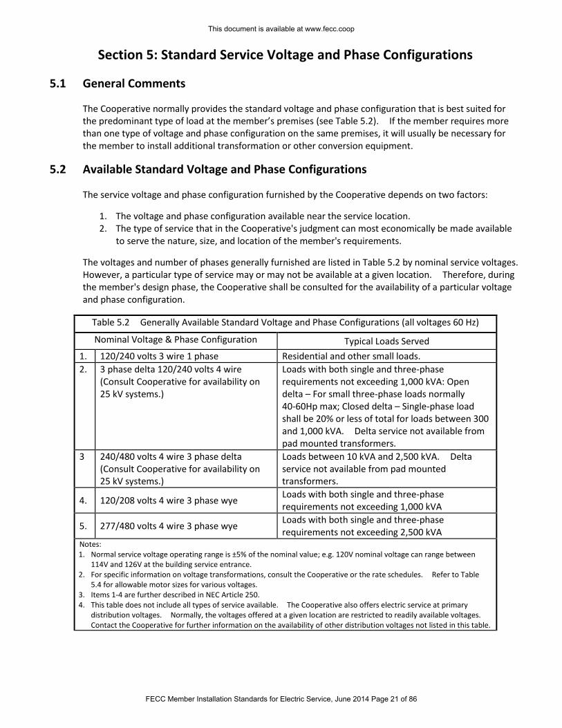
The voltages and number of phases generally furnished are listed in Table 5.2 by nominal service voltages. However, a particular type of service may or may not be available at a given location. Therefore, during the member's design phase, the Cooperative shall be consulted for the availability of a particular voltage and phase configuration.
Table 5.2 Generally Available Standard Voltage and Phase Configurations (all voltages 60 Hz)
Nominal Voltage & Phase Configuration Typical Loads Served
1. 120/240 volts 3 wire 1 phase Residential and other small loads.
2. 3 phase delta 120/240 volts 4 wire (Consult Cooperative for availability on 25 kV systems.)
Loads with both single and three-phase requirements not exceeding 1,000 kVA: Open delta – For small three-phase loads normally 40-60Hp max; Closed delta – Single-phase load shall be 20% or less of total for loads between 300 and 1,000 kVA. Delta service not available from pad mounted transformers.
3 240/480 volts 4 wire 3 phase delta (Consult Cooperative for availability on 25 kV systems.)
Loads between 10 kVA and 2,500 kVA. Delta service not available from pad mounted transformers.
4. 120/208 volts 4 wire 3 phase wye Loads with both single and three-phase requirements not exceeding 1,000 kVA
5. 277/480 volts 4 wire 3 phase wye Loads with both single and three-phase requirements not exceeding 2,500 kVA
Notes: 1. Normal service voltage operating range is ±5% of the nominal value; e.g. 120V nominal voltage can range between
114V and 126V at the building service entrance. 2. For specific information on voltage transformations, consult the Cooperative or the rate schedules. Refer to Table
5.4 for allowable motor sizes for various voltages. 3. Items 1-4 are further described in NEC Article 250. 4. This table does not include all types of service available. The Cooperative also offers electric service at primary
distribution voltages. Normally, the voltages offered at a given location are restricted to readily available voltages. Contact the Cooperative for further information on the availability of other distribution voltages not listed in this table.
This document is available at www.fecc.coop
FECC Member Installation Standards for Electric Service, June 2014 Page 21 of 86
5.3 Voltages for Heating
The recommended voltage for space and water heating is either 208 or 240 volts, depending on the service phase configuration. Heating equipment operated at the member's service voltage should be designed for operation at that voltage. Higher voltages, as available, may be used for larger loads. Resistance furnaces or ovens rated 30 kVA or larger should be three-phase. Consult the Cooperative for service to arc furnaces. Consult the Cooperative for service to residential furnaces or ovens rated 30 kVA or higher prior to purchase of equipment.
5.4 Voltages for Motors
Consult the Cooperative for availability of voltages for motors over 7½ horsepower. Motors may be connected to a 240-volt single-phase service when they are no larger than 7½ horsepower. Motors over 7½ horsepower should be connected to 208 volts three-phase (or other available voltage of 240 volts or higher) where the member has a three-phase service. The Cooperative may require that a motor over 7 ½ horsepower be served by single-phase service where three-phase service is not available unless the member is willing to pay for installing three-phase service.
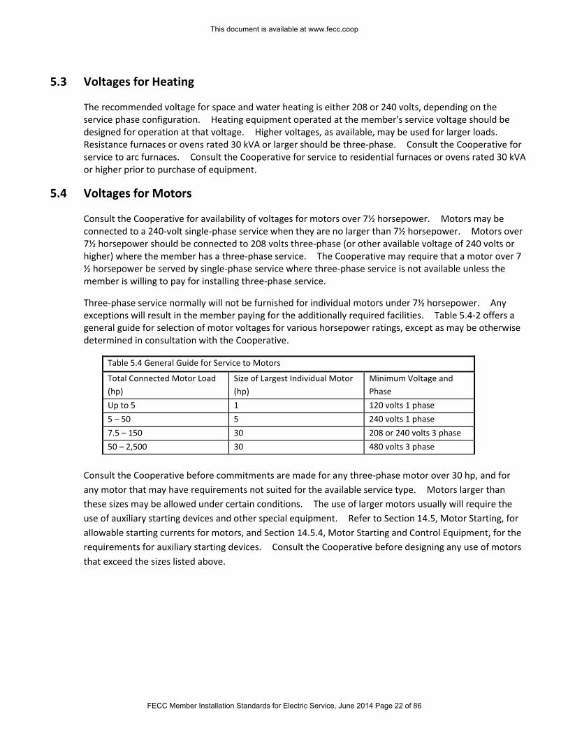
Three-phase service normally will not be furnished for individual motors under 7½ horsepower. Any exceptions will result in the member paying for the additionally required facilities. Table 5.4-2 offers a general guide for selection of motor voltages for various horsepower ratings, except as may be otherwise determined in consultation with the Cooperative.
Table 5.4 General Guide for Service to Motors
Total Connected Motor Load
(hp)
Size of Largest Individual Motor
(hp)
Minimum Voltage and
Phase
Up to 5 1 120 volts 1 phase
5 – 50 5 240 volts 1 phase
7.5 – 150 30 208 or 240 volts 3 phase
50 – 2,500 30 480 volts 3 phase
Consult the Cooperative before commitments are made for any three-phase motor over 30 hp, and for
any motor that may have requirements not suited for the available service type. Motors larger than
these sizes may be allowed under certain conditions. The use of larger motors usually will require the
use of auxiliary starting devices and other special equipment. Refer to Section 14.5, Motor Starting, for
allowable starting currents for motors, and Section 14.5.4, Motor Starting and Control Equipment, for the
requirements for auxiliary starting devices. Consult the Cooperative before designing any use of motors
that exceed the sizes listed above.
This document is available at www.fecc.coop
FECC Member Installation Standards for Electric Service, June 2014 Page 22 of 86
5.5 Voltages for Welders, Elevators, Hoists, Electronic Transmitters, X-Ray Machines, and Other Miscellaneous or Special Equipment
Various voltages may be available for welders, elevators, hoists, electronic transmitters, X-ray machines, and other miscellaneous or special equipment. The Cooperative shall be consulted before the member purchases welding equipment, elevator, or any apparatus with highly fluctuating load characteristics. In some instances, the most practical solution to problems associated with fluctuating loads may be the installation of additional facilities to serve the member. Should the Cooperative install such additional facilities, the member will be required to pay for them.
5.6 Voltages for Overhead or Underground Residential Areas Including Manufactured
Homes, Mobile Home Parks, Trailer Parks, and Individually Located Mobile Homes
Members in residential areas, including manufactured homes, mobile home parks, trailer parks, and individually located mobile homes, with either overhead or underground facilities will be served at 120/240 volts, single-phase. Should three-phase service be required for a specific member, consult the Cooperative for availability and added cost of providing three-phase service before commitments are made.
This document is available at www.fecc.coop
FECC Member Installation Standards for Electric Service, June 2014 Page 23 of 86
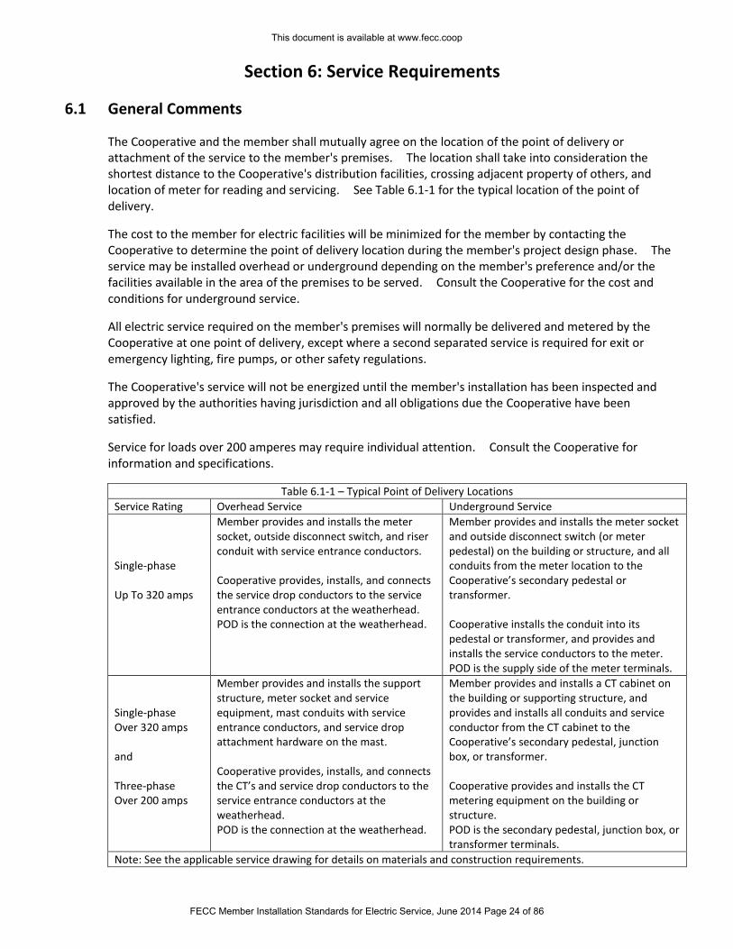
Section 6: Service Requirements
6.1 General Comments
The Cooperative and the member shall mutually agree on the location of the point of delivery or attachment of the service to the member's premises. The location shall take into consideration the shortest distance to the Cooperative's distribution facilities, crossing adjacent property of others, and location of meter for reading and servicing. See Table 6.1-1 for the typical location of the point of delivery.
The cost to the member for electric facilities will be minimized for the member by contacting the Cooperative to determine the point of delivery location during the member's project design phase. The service may be installed overhead or underground depending on the member's preference and/or the facilities available in the area of the premises to be served. Consult the Cooperative for the cost and conditions for underground service.
All electric service required on the member's premises will normally be delivered and metered by the Cooperative at one point of delivery, except where a second separated service is required for exit or emergency lighting, fire pumps, or other safety regulations.
The Cooperative's service will not be energized until the member's installation has been inspected and approved by the authorities having jurisdiction and all obligations due the Cooperative have been satisfied.
Service for loads over 200 amperes may require individual attention. Consult the Cooperative for information and specifications.
Table 6.1-1 – Typical Point of Delivery Locations
Service Rating Overhead Service Underground Service
Single-phase Up To 320 amps
Member provides and installs the meter socket, outside disconnect switch, and riser conduit with service entrance conductors. Cooperative provides, installs, and connects the service drop conductors to the service entrance conductors at the weatherhead. POD is the connection at the weatherhead.
Member provides and installs the meter socket and outside disconnect switch (or meter pedestal) on the building or structure, and all conduits from the meter location to the Cooperative’s secondary pedestal or transformer. Cooperative installs the conduit into its pedestal or transformer, and provides and installs the service conductors to the meter. POD is the supply side of the meter terminals.
Single-phase Over 320 amps and Three-phase Over 200 amps
Member provides and installs the support structure, meter socket and service equipment, mast conduits with service entrance conductors, and service drop attachment hardware on the mast. Cooperative provides, installs, and connects the CT’s and service drop conductors to the service entrance conductors at the weatherhead. POD is the connection at the weatherhead.
Member provides and installs a CT cabinet on the building or supporting structure, and provides and installs all conduits and service conductor from the CT cabinet to the Cooperative’s secondary pedestal, junction box, or transformer. Cooperative provides and installs the CT metering equipment on the building or structure. POD is the secondary pedestal, junction box, or transformer terminals.
Note: See the applicable service drawing for details on materials and construction requirements.
This document is available at www.fecc.coop
FECC Member Installation Standards for Electric Service, June 2014 Page 24 of 86
6.2 Right-of-Way for Service Facilities
The property owner(s) will grant, at no cost to the Cooperative, right-of-way suitable to the Cooperative for the installation of the Cooperative's facilities. The Cooperative may require a written right-of-way permit document for execution by the property owner(s). The Cooperative may require the member's assistance in obtaining right(s)-of-way from adjacent property owner(s).
The Cooperative also shall be provided, at no cost, written agreements covering proper easements if:
1. Primary facilities are installed on private property; 2. Secondary facilities are to be installed on the member's premises that could serve one or more
members on adjoining properties; 3. Facilities cross over or under private property, such as, cross country, adjoining highways and
roadways, within subdivisions, etc., and 4. Facilities are constructed within the confines of a highway or roadway that exists by virtue of
servitude only.
All parties, i.e., in-fee land owner(s), grantee(s), shall give their consent.
6.3 Initial Clearing of Property for Right-of-Way
The Cooperative is responsible for the cost of preparing the initial right-of-way for overhead service installations up to the meter pole location. If agreeable to both parties, the member may perform the clearing as instructed by the Cooperative on all property owned by the member. In either case, the member will be responsible for removal of all debris on the member’s property. For underground service routes, the member is responsible for clearing and maintaining the right-of-way from the Cooperative’s source location to the meter location.
6.4 Relocation of Cooperative's Facilities
The Cooperative will move or relocate the Cooperative's facilities, where practical to do so, at the request of the member. The member may be required to provide consideration (i.e., payment, furnishing of installed facilities, etc.) in exchange for the relocation.
This document is available at www.fecc.coop
FECC Member Installation Standards for Electric Service, June 2014 Page 25 of 86
Section 7: Permanent Overhead Service
7.1 General Comments
Consult the Cooperative for the closest and most reasonable location for the service drop attachment. Ordinarily, only one type of service and one service drop is permitted to the member's premises. The Cooperative normally will make connection to the member’s service entrance conductors. Connection shall be made only after the member's wiring has passed inspection and has been approved by the authorities having jurisdiction. From the point where the Cooperative's overhead service drop terminates, the member shall install service entrance wires to the meter socket and service entrance switch or circuit breaker panel in accordance with the requirements of the NEC, NESC, or other authorities having jurisdiction.
Not less than three feet of each conductor of the service entrance cable or wires shall be left extending beyond the weather head for connection to Cooperative's service drop. For three-phase services, like phases shall be identified appropriately and marked on both ends. High-legs in four-wire delta services shall be marked with orange tape on both ends. Neutrals shall be marked with white tape on both ends. Neutrals may be bare wire. The Cooperative will make the connection(s) to the cooperative’s service drop conductors. It is the member's responsibility to ensure that like phases are appropriately marked and connected together on the supply side and the load side of the metering equipment. Refer to the following drawings for overhead service installation specifications:
Drawing Description
7.1-1 Overhead Meter On House – Attachment to Wall or Fascia
7.1-2 Overhead Meter On House – Attachment to Service Mast
7.1-3 Meter On Pole – Single-phase (underground load connection)
7.1-4 Meter On Pole – Single-phase (overhead load connection)
7.1-5 Meter On Pole – Three-phase (underground load connection)
For temporary overhead service refer to Section 4.5, Temporary Service, and Drawing 4.5-1.
7.2 Point of Attachment on Home or Building
The point of attachment:
1. shall be provided and installed by the member for the Cooperative's service drop to the member's premises,
2. shall be of sufficient height to permit the Cooperative's service drop to conform to the requirements of the National Electrical Safety Code and any other controlling codes, ordinances, or orders of authorities having jurisdiction,
3. shall not exceed 21 feet in height from final grade to attachment point for residential services, and shall be either accessible to Cooperative’s bucket truck or have enough surface (such as a wall or building structure) and sufficient ground space on same member’s property to safely support a ladder,
4. shall have a clear line of sight to the pole from which the service wire is or will be attached, 5. shall not have any other attachments (such as telephone, cable, Internet) as per NEC Article 230.
See Drawing 7.2-1 and Section 11.5 for attachment location details.
The member may be required to install a service mast to maintain ground clearance. When a service mast extends above the roof, the point of attachment and clearances above the roof shall conform to the National Electrical Code or other controlling codes. Where a service mast is used for the support of service drop conductors it shall be of adequate strength and supported by braces or guy wire to withstand
This document is available at www.fecc.coop
FECC Member Installation Standards for Electric Service, June 2014 Page 26 of 86
safely the strain imposed by these drops and be no higher than 60” higher than the roof. Where the raceway type service mast is used, all raceway fittings shall be identified for use with service mast. Raintight service head shall be used at the point of connection to service drop conductors.
7.3 Clearances
The point of attachment of the service drop (150 volts line to ground or less) shall be high enough to allow for the service drop conductors to have the following minimum clearances at their lowest point (To allow for typical cable sag, point of attachment is usually 1 ½ - 2 feet higher than minimum clearance below. Consult the Cooperative):
12 feet over areas of pedestrian traffic, residential driveways, and commercial areas not subject to truck traffic.
16 feet over roads, streets, alleys, non-residential driveways, and other areas subject to truck traffic.
Where the height of a residential building does not permit service drops to meet these values, the clearances may be reduced to the following (see NESC Table 232-1):
150V or less to ground For residential driveways only
Spaces accessible to pedestrian traffic only
Insulated Service drops 12 10
Insulated drip loops 10 10
The point of attachment shall never be installed so the service drop would extend over a swimming pool or any other permanent or temporary structure. See Section 2.3 Distance Requirements for Member Structures for swimming pool clearances.
The construction of any structure near, under, or over Cooperative lines may cause a code and/or safety violation. Consult the Cooperative concerning all clearances.
7.4 Length of Service Drop
The clearance of the unsupported length of the service drop from the Cooperative's facilities to the first point of attachment will in no case violate the clearances given in previous section. The allowable unsupported length of a service drop shall depend on wire sizes as shown in the table Drawing 7.1-1, and Drawing 7.1-2. Other significant factors and conditions at the member's property may affect these standard lengths. Consult the Cooperative for length limitations.
7.5 Method of Attachment
The service drop will be attached to the pole, building or approved extension by minimum ½” galvanized steel eyebolt; screw-in house knobs are not acceptable. The member shall provide suitable reinforcement or backing for secure mounting of attachment fittings and adequate anchorage of the service drop as well as at the appropriate height with the appropriate separation. Refer to Drawing 7.1-1 or Drawing 7.1-2 for residential installations.
This document is available at www.fecc.coop
FECC Member Installation Standards for Electric Service, June 2014 Page 27 of 86
7.6 Extension of Overhead Distribution Facilities
The Cooperative standard for overhead distribution facilities is installation on front lot easement. Consult the Cooperative early in the design phase for more information on other options.
A member's service location may require the Cooperative to incur expense greater than normally allowed in providing the service. Extension of primary overhead distribution lines, relocation of Cooperative facilities or removal of Cooperative facilities are examples of situations which occur. When such a situation exists, the Cooperative may require payment from the member in addition to the amount normally charged. For complete details on payment options, consult the Cooperative's policy for extension of overhead electric distribution facilities.
This document is available at www.fecc.coop
FECC Member Installation Standards for Electric Service, June 2014 Page 28 of 86
Section 8: Underground Service and Installations
8.1 General Comments
Underground electric distribution facilities are available in many, but not all, areas of the Cooperative’s service territory. Where underground distribution is available, and technically and economically feasible, the member may choose to take underground electric service; in some areas, such as underground subdivisions, the member may be required to take underground service. In either case, the member will be required to pay the additional cost, if any, in excess of the cost of an overhead system.
Single-phase underground service for residential and small commercial members normally will be 120/240 volts, three-wire. Larger commercial and industrial members normally will be served at 120/208Y or 277/480Y volts, four-wire.
In all cases, the member shall provide right-of-way for the underground cable route and for poles, transformers and other above-ground equipment locations. The member shall be responsible for all excavation to accommodate the Cooperative’s primary underground system and/or the member’s secondary underground system. The member will also be responsible for replacing any landscaping, shrubs, trees, or paved areas that are removed or disturbed to accommodate the installation repair, or replacement of Cooperative-owned underground facilities on the member’s premises.
8.2 Ownership of Facilities
The Cooperative generally will own and operate all facilities on the Cooperative side of the point of delivery. The Cooperative will own the meter in all cases, and will own the CT’s and meter socket in CT installations (CT installations normally are used for services rated above 320A). Specific ownership requirements for various installations can be found in Section 8.6, Installations for Residential & Small Commercial Underground Service Rated up to 320 Amps, and Section 8.7, Installations for Large Commercial & Industrial Underground Services Rated above 320 Amps.
8.3 Initial Clearing of Property for Underground Service
The member:
1. Requesting a new service is responsible for preparing the initial right-of-way. 2. Shall notify ONECALL 48 hours before digging and shall have ONECALL locate all underground
facilities before digging. Dial 811 to contact ONECALL. 3. Shall be responsible for performing all grubbing and clearing as instructed by the Cooperative on
all property owned by the member. 4. Will be responsible for removal of all debris and shall bring the easement to final grade prior to
any installation of facilities by the Cooperative. 5. Shall be responsible for costs associated with raising, lowering or relocating facilities due to
changes in the surface grade after installation of the Cooperative's facilities.
At the Cooperative's option, the Cooperative may prepare the right-of-way and will be reimbursed by the member.
8.4 Agreement for Underground Service
The member may be required to execute an agreement that will set forth ownership and maintenance responsibilities, characteristics of the services covered, and any financial arrangements. An agreement
This document is available at www.fecc.coop
FECC Member Installation Standards for Electric Service, June 2014 Page 29 of 86
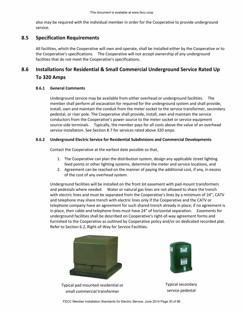
also may be required with the individual member in order for the Cooperative to provide underground service.
8.5 Specification Requirements
All facilities, which the Cooperative will own and operate, shall be installed either by the Cooperative or to the Cooperative's specifications. The Cooperative will not accept ownership of any underground facilities that do not meet the Cooperative's specifications.
8.6 Installations for Residential & Small Commercial Underground Service Rated Up
To 320 Amps
8.6.1 General Comments
Underground service may be available from either overhead or underground facilities. The member shall perform all excavation for required for the underground system and shall provide, install, own and maintain the conduit from the meter socket to the service transformer, secondary pedestal, or riser pole. The Cooperative shall provide, install, own and maintain the service conductors from the Cooperative’s power source to the meter socket or service equipment source-side terminals. Typically, the member pays for all costs above the value of an overhead service installation. See Section 8.7 for services rated above 320 amps.
8.6.2 Underground Electric Service for Residential Subdivisions and Commercial Developments
Contact the Cooperative at the earliest date possible so that,
1. The Cooperative can plan the distribution system, design any applicable street lighting feed points or other lighting systems, determine the meter and service locations, and
2. Agreement can be reached on the manner of paying the additional cost, if any, in excess of the cost of any overhead system.
Underground facilities will be installed on the front lot easement with pad-mount transformers and pedestals where needed. Water or natural gas lines are not allowed to share the trench with electric lines and must be separated from the Cooperative’s lines by a minimum of 24”; CATV and telephone may share trench with electric lines only if the Cooperative and the CATV or telephone company have an agreement for such shared trench already in place; if no agreement is in place, then cable and telephone lines must have 24” of horizontal separation. Easements for underground facilities shall be described on Cooperative's right-of-way agreement forms and furnished to the Cooperative as outlined by Cooperative policy and/or on dedicated recorded plat. Refer to Section 6.2, Right-of-Way for Service Facilities.
Typical pad mounted residential or
small commercial transformer
Typical secondary
service pedestal
This document is available at www.fecc.coop
FECC Member Installation Standards for Electric Service, June 2014 Page 30 of 86
Members within an underground development adjacent to an overhead distribution system may be served with an underground service from the overhead system.
8.6.3 Underground Service Rated up to 320 Amps from an Underground Distribution System.
A member may elect or be required to take electric service through an underground service from an underground distribution system and may be required to pay in some manner the additional cost, if any, in excess of the cost of an overhead system. The member shall provide, install, own and maintain the conduit from the meter socket to the service transformer or pedestal. The Cooperative shall provide, install, own, and maintain the underground conductors in the conduit system for services rated 320 amps or less. See Section 8.7 for services rated above 320 amps.
8.6.4 Underground Service Rated up to 320 Amps from Overhead Distribution System
The member may elect or be required to take service through an underground service from an overhead distribution system and may be required to pay in some manner the additional cost, if any, in excess of the cost of an overhead service. The member shall provide, install, own and maintain the conduit from the meter socket to the Cooperative’s pole. The Cooperative shall provide, install, own, and maintain the pole riser conduit and the underground conductors in the conduit system for services rated 320 amps or less. See Section 8.7 for services rated above 320 amps.
8.6.5 Underground Service Replacing Existing Overhead Service
An existing member served with an overhead service may request the removal of the overhead service and installation of a new underground service. If the existing service is of adequate size to serve the load, the member is responsible for paying the total estimated cost of the job plus the removal cost less salvage. Where the existing service is not adequate to serve the increased load, the member shall pay the difference between the estimated cost of an underground service and a new overhead service. Consult the Cooperative for information and specifications.
8.7 Installations for Large Commercial & Industrial Underground Service Rated Above
320 Amps
8.7.1 General Comments
Underground service may be available from either overhead or underground facilities. The member shall provide, install, own and maintain the service conductors and conduit system from the service equipment to the service transformer or secondary pedestal for service rated above 320A. All secondary service design and installation is the responsibility of the member, and shall meet the requirements of the Cooperative, the NEC, and local authorities having jurisdiction. See Section 8.6 for services rated up to 320 amps.
8.7.2 Junction Box Requirements
A junction box is not required when the member provides, owns, installs and maintains the secondary wire to the Cooperative’s transformer. If the Cooperative owns the service conductors from the transformer to the member’s premises, the member shall supply a UL listed NEMA 3R-rated Cooperative-approved junction box or a UL-listed Cooperative-approved alternative with a locking mechanism to secure it suitable for a Cooperative padlock. Junction boxes used for various situations are shown in Drawing 11.6-2, Drawing 11.6-3, and Drawing 11.8-2.
This document is available at www.fecc.coop
FECC Member Installation Standards for Electric Service, June 2014 Page 31 of 86
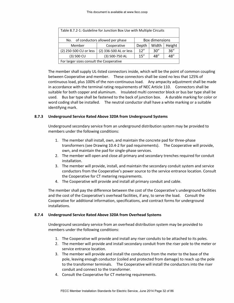
Table 8.7.2-1: Guideline for Junction Box Use with Multiple Circuits
No. of conductors allowed per phase Box dimensions Member Cooperative Depth Width Height
(2) 250-500 CU or less (2) 336-500 AL or less 12” 30” 36” (3) 500 CU (3) 500-750 AL 15” 48” 48”
For larger sizes consult the Cooperative
The member shall supply UL-listed connectors inside, which will be the point of common coupling between Cooperative and member. These connectors shall be sized no less that 125% of continuous load, plus 100% of the non-continuous load. Any ampacity adjustment shall be made in accordance with the terminal rating requirements of NEC Article 110. Connectors shall be suitable for both copper and aluminum. Insulated multi connector block or bus bar type shall be used. Bus bar type shall be fastened to the back of junction box. A durable marking for color or word coding shall be installed. The neutral conductor shall have a white marking or a suitable identifying mark.
8.7.3 Underground Service Rated Above 320A from Underground Systems
Underground secondary service from an underground distribution system may be provided to members under the following conditions:
1. The member shall install, own, and maintain the concrete pad for three-phase transformers (see Drawing 10.4-2 for pad requirements). The Cooperative will provide, own, and maintain the pad for single-phase services.
2. The member will open and close all primary and secondary trenches required for conduit installation.
3. The member will provide, install, and maintain the secondary conduit system and service conductors from the Cooperative’s power source to the service entrance location. Consult the Cooperative for CT metering requirements.
4. The Cooperative will provide and install all primary conduit and cable.
The member shall pay the difference between the cost of the Cooperative’s underground facilities and the cost of the Cooperative’s overhead facilities, if any, to serve the load. Consult the Cooperative for additional information, specifications, and contract forms for underground installations.
8.7.4 Underground Service Rated Above 320A from Overhead Systems
Underground secondary service from an overhead distribution system may be provided to members under the following conditions:
1. The Cooperative will provide and install any riser conduits to be attached to its poles. 2. The member will provide and install secondary conduit from the riser pole to the meter or
service entrance location. 3. The member will provide and install the conductors from the meter to the base of the
pole, leaving enough conductor (coiled and protected from damage) to reach up the pole to the transformer terminals. The Cooperative will install the conductors into the riser conduit and connect to the transformer.
4. Consult the Cooperative for CT metering requirements.
This document is available at www.fecc.coop
FECC Member Installation Standards for Electric Service, June 2014 Page 32 of 86
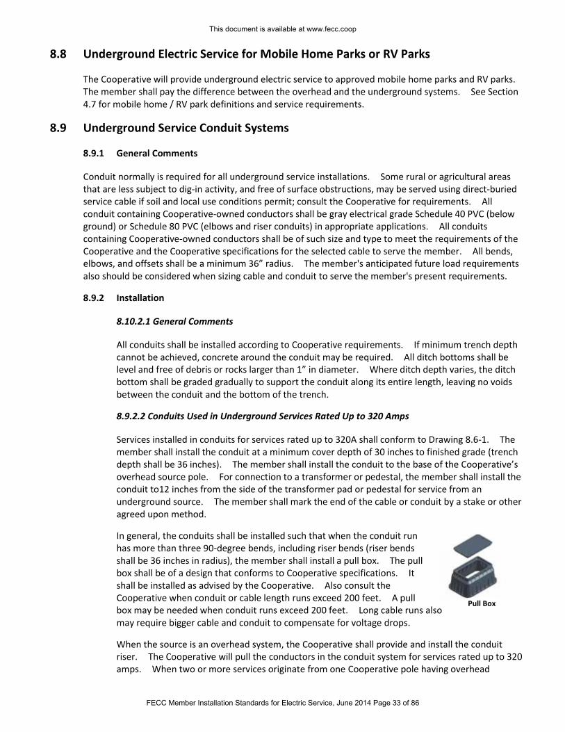
8.8 Underground Electric Service for Mobile Home Parks or RV Parks
The Cooperative will provide underground electric service to approved mobile home parks and RV parks. The member shall pay the difference between the overhead and the underground systems. See Section 4.7 for mobile home / RV park definitions and service requirements.
8.9 Underground Service Conduit Systems
8.9.1 General Comments
Conduit normally is required for all underground service installations. Some rural or agricultural areas that are less subject to dig-in activity, and free of surface obstructions, may be served using direct-buried service cable if soil and local use conditions permit; consult the Cooperative for requirements. All conduit containing Cooperative-owned conductors shall be gray electrical grade Schedule 40 PVC (below ground) or Schedule 80 PVC (elbows and riser conduits) in appropriate applications. All conduits containing Cooperative-owned conductors shall be of such size and type to meet the requirements of the Cooperative and the Cooperative specifications for the selected cable to serve the member. All bends, elbows, and offsets shall be a minimum 36” radius. The member's anticipated future load requirements also should be considered when sizing cable and conduit to serve the member's present requirements.
8.9.2 Installation
8.10.2.1 General Comments
All conduits shall be installed according to Cooperative requirements. If minimum trench depth cannot be achieved, concrete around the conduit may be required. All ditch bottoms shall be level and free of debris or rocks larger than 1” in diameter. Where ditch depth varies, the ditch bottom shall be graded gradually to support the conduit along its entire length, leaving no voids between the conduit and the bottom of the trench.
8.9.2.2 Conduits Used in Underground Services Rated Up to 320 Amps
Services installed in conduits for services rated up to 320A shall conform to Drawing 8.6-1. The member shall install the conduit at a minimum cover depth of 30 inches to finished grade (trench depth shall be 36 inches). The member shall install the conduit to the base of the Cooperative’s overhead source pole. For connection to a transformer or pedestal, the member shall install the conduit to12 inches from the side of the transformer pad or pedestal for service from an underground source. The member shall mark the end of the cable or conduit by a stake or other agreed upon method.
In general, the conduits shall be installed such that when the conduit run has more than three 90-degree bends, including riser bends (riser bends shall be 36 inches in radius), the member shall install a pull box. The pull box shall be of a design that conforms to Cooperative specifications. It shall be installed as advised by the Cooperative. Also consult the Cooperative when conduit or cable length runs exceed 200 feet. A pull box may be needed when conduit runs exceed 200 feet. Long cable runs also may require bigger cable and conduit to compensate for voltage drops.
When the source is an overhead system, the Cooperative shall provide and install the conduit riser. The Cooperative will pull the conductors in the conduit system for services rated up to 320 amps. When two or more services originate from one Cooperative pole having overhead
Pull Box
This document is available at www.fecc.coop
FECC Member Installation Standards for Electric Service, June 2014 Page 33 of 86
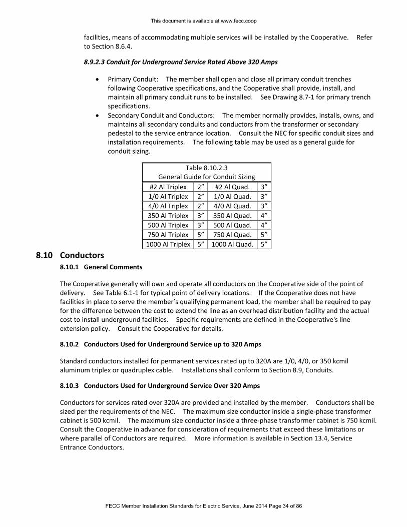
facilities, means of accommodating multiple services will be installed by the Cooperative. Refer to Section 8.6.4.
8.9.2.3 Conduit for Underground Service Rated Above 320 Amps
Primary Conduit: The member shall open and close all primary conduit trenches following Cooperative specifications, and the Cooperative shall provide, install, and maintain all primary conduit runs to be installed. See Drawing 8.7-1 for primary trench specifications.
Secondary Conduit and Conductors: The member normally provides, installs, owns, and maintains all secondary conduits and conductors from the transformer or secondary pedestal to the service entrance location. Consult the NEC for specific conduit sizes and installation requirements. The following table may be used as a general guide for conduit sizing.
Table 8.10.2.3 General Guide for Conduit Sizing
#2 Al Triplex 2” #2 Al Quad. 3”
1/0 Al Triplex 2” 1/0 Al Quad. 3”
4/0 Al Triplex 2” 4/0 Al Quad. 3”
350 Al Triplex 3” 350 Al Quad. 4”
500 Al Triplex 3” 500 Al Quad. 4”
750 Al Triplex 5” 750 Al Quad. 5”
1000 Al Triplex 5” 1000 Al Quad. 5”
8.10 Conductors 8.10.1 General Comments
The Cooperative generally will own and operate all conductors on the Cooperative side of the point of delivery. See Table 6.1-1 for typical point of delivery locations. If the Cooperative does not have facilities in place to serve the member’s qualifying permanent load, the member shall be required to pay for the difference between the cost to extend the line as an overhead distribution facility and the actual cost to install underground facilities. Specific requirements are defined in the Cooperative's line extension policy. Consult the Cooperative for details.
8.10.2 Conductors Used for Underground Service up to 320 Amps
Standard conductors installed for permanent services rated up to 320A are 1/0, 4/0, or 350 kcmil aluminum triplex or quadruplex cable. Installations shall conform to Section 8.9, Conduits.
8.10.3 Conductors Used for Underground Service Over 320 Amps
Conductors for services rated over 320A are provided and installed by the member. Conductors shall be sized per the requirements of the NEC. The maximum size conductor inside a single-phase transformer cabinet is 500 kcmil. The maximum size conductor inside a three-phase transformer cabinet is 750 kcmil. Consult the Cooperative in advance for consideration of requirements that exceed these limitations or where parallel of Conductors are required. More information is available in Section 13.4, Service Entrance Conductors.
This document is available at www.fecc.coop
FECC Member Installation Standards for Electric Service, June 2014 Page 34 of 86
8.11 Termination of Members’ Conductors in Cooperative’s Transformers
The Cooperative will furnish and install terminals for copper or aluminum secondary conductors in sizes 1/0, 2/0, 4/0, 350 kcmil, 500 kcmil, and 750 kcmil. Consult the Cooperative early in the design phase if other size conductors are to be used. The Cooperative normally will terminate the conductor and bolt it to the terminals of the transformer. The phasing and proper conductor length will be the responsibility of the member regardless of who installs the terminals or bolts the terminals to the transformer terminals. More information is available in Section 13.4, Service Entrance Conductors.
8.12 Metering for Underground Service
The meter installation shall be located outside of a building or structure. Refer to Section 11.5, Location of Meter Installations. Outside disconnect switches are required for all self-contained meters rated over 320A and shall be mounted outside the building within 2 feet of the side of the meter socket. Outside disconnects are not required for CT-rated meters, but are recommended – always check with local authorities regarding the location of the service disconnect. Prior approval shall be obtained from the Cooperative for the installation of any service equipment directly below the meter sockets. Also see NEC Article 230.
If a single transformer-rated metering installation is to be used in connection with a three-phase pad mount transformer installation, the meter typically will be installed on the pad mount transformer. Special metering options may be available with approval of the Cooperative. The member shall bear the additional cost made necessary by the special metering options.
8.13 Transformers Used in Underground Installations
The Cooperative generally will own and operate all transformers on the Cooperative’s side of the point of delivery. The Cooperative provides and installs the transformer pad for single phase transformers, and the member provides and installs the transformer pad for three phase transformers. Pads, vaults, enclosures, etc. (when used) shall conform to Cooperative specifications. Always consult the Cooperative during the planning stage for transformer location and pad construction details. See Section 10.4 Pad Mount Transformers, for more information.
This document is available at www.fecc.coop
FECC Member Installation Standards for Electric Service, June 2014 Page 35 of 86

Section 9: Not used in this edition
Section reserved for future use.
This document is available at www.fecc.coop
FECC Member Installation Standards for Electric Service, June 2014 Page 36 of 86
Section 10: Transformers
10.1 General Comments
When large concentrated loads or long distances are encountered, it is frequently necessary to install transformers on or in the member's property. In such cases, high voltage conductors are taken directly to the transformer. Whether transformers are to be installed outside, on, or in the member's property, the member shall provide a suitable location. The member shall consult the Cooperative regarding the location, size, and construction of the facilities during the design and planning phase. Installations will vary so widely that the member shall consult with the Cooperative so that arrangements can be worked out to the benefit of both parties.
In the interest of public safety, it is imperative that all transformers be readily accessible to the Cooperative at any time of the day or night. In all but the most unusual cases, the member shall equip each gate (or other barrier) between the transformer and the nearest public access with locks that can be opened by the Cooperative. These locks will be provided by the Cooperative and installed by the member.
The Cooperative will not energize its facilities until the installation meets all of the following requirements:
1. Made in accordance with manufacturer recommendations and engineering standards. 2. Approved by authorities having jurisdiction. 3. Acceptable to the Cooperative.
Adequate access and support to accommodate line trucks or other necessary lifting and hauling equipment shall be provided and maintained by the member to allow for maintenance, operation or replacement of equipment at all hours.
10.2 Fences, Screen Walls, Decorative Walls
The Cooperative will not construct, reimburse the member, or accept ownership and maintenance responsibility of any fences, screen walls, or decorative walls around pad-mount transformer installations or vaults. Prior written approval shall be obtained from the Cooperative before the member constructs such walls or fences. Adequate space and means of ingress and egress (such as wide removable panels) shall be provided to operate, maintain, remove and replace transformer, metering or other equipment located behind the fence or wall. In general, all pad mounted transformers shall have at least 3’ unobstructed space between the back and sides, and 12’ unobstructed space to the front (door opening) side.
10.3 Types of Transformer Installations
The Cooperative provides electric service from one of the following general transformer installations:
1. Pole-mounted transformers, one or cluster of two or three transformers 2. Two-pole transformer platform 3. Pad-mounted transformers,
This document is available at www.fecc.coop
FECC Member Installation Standards for Electric Service, June 2014 Page 37 of 86
10.4 Pad Mount Transformers
Pad mount transformers generally are provided, owned and maintained by the Cooperative for underground service. Transformers shall be located in areas that are accessible to heavy line trucks for installation or replacement purposes. If located in or near parking areas or traffic ways, the transformer shall be protected from vehicle damage by suitable barriers.
Transformers located within 10 feet of buildings shall be situated away from doorways, open stairways, fire escapes, and windows. For ready access to pad-mount transformers, a minimum clearance of three feet from the side and back of the transformer and 12 feet from the front (door opening) side of the transformer shall be maintained at all times. See Drawing 10.4-1 for other requirements on transformer placement.
The Cooperative generally will furnish and install single-phase transformer pads. Three-phase transformer pads or slabs shall be provided by the member, and shall conform to Cooperative specifications (see Drawing 10.4-2). When supporting walls or foundations are needed for the transformer installation, the member will be responsible for the design and installation of the supporting foundation and for obtaining approval of the design by the Cooperative. Consult the Cooperative.
For all pad-mount transformer applications, the member will provide, install, and maintain the conduit(s) from the member’s premises or meter location to the transformer location.
10.5 Termination of Secondary Conductors to Transformers for Services Rated Above
320 Amps
Terminals for secondary conductors shall be installed as provided in Section 8.11, Termination of member’s Conductors in Cooperative’s Pad-Mounted Transformers.
The phasing, sizing and proper length of conductors is the sole responsibility of the member. The member also shall be responsible for properly marking the phases. The Cooperative generally will make connection of the terminals to the connectors of the transformer.
This document is available at www.fecc.coop
FECC Member Installation Standards for Electric Service, June 2014 Page 38 of 86
Section 11: Metering Installations and Equipment
11.1 General Comments
11.1.1 Responsible Parties
The metering equipment usually is installed on the member's premises as part of the service entrance equipment; therefore provisions shall be made for it in the member's installation. The Cooperative will provide, as required, meters, metering transformers, relays, color-coded cable and CT-rated meter sockets. The type of equipment supplied will depend on the requirements of the applicable rate schedule and the Cooperative's standard practices.
Self contained, direct connected metering generally is used for single and three-phase services rated up to 320A of load current, as determined by the Cooperative. Self-contained metering normally is located on the outside wall of the building being served, or may be mounted on a meter pole or free-standing metering rack, as required. The member is required to provide and install the meter socket, disconnect switch, and all associated materials. See the drawings in this Standard for service installation details.
CT-rated metering installations are used for single- or three-phase services rated over 320A, as determined by the Cooperative. When served from a dedicated transformer, the CT metering usually will be located on the pad mount transformer for underground service, or on the transformer pole for overhead service; the Cooperative provides and installs all metering equipment and associated materials when located on the pad-mount transformer or meter pole. In cases where the transformer is connected to more than one service location, the CT metering will be mounted on the building being served; the member provides and installs the CT cabinet. See Drawing 11.8-2 (underground service) or 11.8-3 (overhead service) for CT cabinet installation details.
The member will be required to provide the Cooperative with information regarding the total connected load. The member may be required to provide and/or install the meter socket, metering transformer enclosure and adequate attachments or devices for attaching Cooperative's metering facilities to the building. (This may require running conduit through eaves of roof and other similar necessities that could alter the member's building.)
11.1.2 Meter Socket Specifications
1. All meter sockets shall utilize NEMA 3R construction and be UL 414 listed and comply with ANSI C12.7 standards.
2. All meter sockets shall provide for a pad lock and be in serviceable condition. Member shall properly seal all unused openings on the meter socket assembly.
3. Ringless-type sockets are preferred. If ring-type sockets are used, member shall supply a meter ring to secure the meter in the socket. The ring shall be stainless steel with provision for a meter seal.
4. Factory assembled combination meter and disconnect enclosures are often the best solution for service equipment. All factory assembled enclosures shall be listed as service equipment. Source-side and load-side conductors shall be secured behind separate barriers. Cooperative personnel shall have access to source-side conductors without exposing the load-side conductors.
5. All sockets except residential single-phase less than 320 Amps shall have a manual mechanical gang operated bypass switch. Horn bypasses are not allowed. Service entrance conductors shall enter and stay opposite of the by-pass switch.
6. The lugs in 320A meter sockets shall accept up to 500 MCM conductors. 7. For five-terminal meter sockets, the fifth terminal shall be physically secured to the meter socket. It
should be relocatable but shall be attached securely to the socket in the proposed operating position.
This document is available at www.fecc.coop
FECC Member Installation Standards for Electric Service, June 2014 Page 39 of 86
8. In accordance with all applicable codes, a socket shall be installed properly and used in the application for which it is designed. Load and supply wires shall not cross in the meter socket. Overhead sockets are required in overhead installations and underground sockets are required in underground installations. Meter socket enclosures shall be large enough to accommodate conductor size (see NEC Article 300). For meter sockets in underground installations, minimum size shall be D 4 1/8” X W 11” X H 15 ½“.
11.1.3 Current Transformer (CT) Enclosure Specifications
The Cooperative specifies instrument transformer enclosures that accommodate the Cooperative’s equipment standards. These standards may differ from manufacturer’s specifications if determined only by ampere ratings. Therefore, members or their agents should determine the enclosure size based upon the size and number of service conductors as well as ampere ratings. Instrument transformers shall be bolted to the back-plate and each shall be capable of being removed individually. The back plate is in addition to the back wall of the enclosure and shall be metal or ¾” plywood. All enclosures shall be rainproof NEMA 3R rated.
For 600 amps or below or single conductors of 750 kcmil or greater and parallel conductors up to and including 500 kcmil, the minimum requirements are: Aluminum or 14 gauge G90 steel enclosure, 14”D X 32”W X 40”H, with a back-plate, front cover that is hinged and sealing latches.
For 600-800 amps or parallel conductors greater than 500 kcmil, the minimum requirements are: Aluminum or 14 gauge G90 steel enclosure, 14”D X 32”W x 54”H, with a back-plate, front cover that is hinged and sealing latches.
For 800 amps or parallel conductors greater than 750 kcmil contact Cooperative for requirements.
Service connections cannot be made in an instrument transformer enclosure. A suitable junction box must be provided adjacent to the CT enclosure.
11.2 Meter Connections and Seals
The Cooperative shall install the meters, seal all meters, and seal all instrument transformer enclosures. Except as noted below, only the Cooperative and its authorized agents are permitted to break or replace a seal, or to remove or change a meter. Under certain conditions, and with specific approval of the Cooperative, authorization may be obtained by a licensed electrical contractor to remove a Cooperative meter seal. The contractor shall obtain approval prior to removing the meter seal, or notify the Cooperative after doing so under unusual circumstances. Any infringement or violation shall be dealt with in accordance with the Cooperative procedure for dealing with meter tampering.
11.3 Meter Clearance
Meters and metering equipment enclosures shall be mounted in locations that will provide at least 15 inches clearance on all sides and at least three feet in front. Exceptions to this section must be approved by the Cooperative. Equipment and clearances shall be within member’s property.
Clearance between an electric meter and natural gas meters shall be at least 3’ in any direction. Clearance between an electric meter and LPG storage tanks shall be at least 10’ in any direction.
An electric meter is a possible source of ignition whether located inside or outside of a building.
This document is available at www.fecc.coop
FECC Member Installation Standards for Electric Service, June 2014 Page 40 of 86
11.4 Outdoor Meters
An outdoor meter installation is the Cooperative’s standard for all new installations and where practicable on rewired installations. (For example, locations inside porches or beneath carports are not considered as being outdoors.) To facilitate reading by both the member and the Cooperative and to provide accessibility for testing, the Cooperative requires that outdoor meters be mounted between four and six feet above finished grade.
11.5 Location of Meter Installations
In all cases, the member and the Cooperative mutually shall agree on the meter location. The Cooperative always should be consulted to determine the meter location on any new service or building renovation.
For residential service, the meter is to be located on the outside of the building on the side of residences, and outside of fences on the side most economical to reach the Cooperative’s facilities. This location minimizes the installation cost for the member and the Cooperative. The Cooperative will endeavor to select a meter location that will be satisfactory and economical for the member and at the same time convenient to the Cooperative in providing the necessary connections as part of the service entrance installation. Prior written approval of the Cooperative is required to locate the meter other than in the preferred location, and the member shall pay any and all appropriate charges. Approval of the Cooperative to locate the meter elsewhere will not be given unless the meter is, and will remain, readily accessible. Construction of pools, decks, fences or any structure near, under or over electrical facilities may cause a code and/or safety violation and may require relocation of the meter, connection point and/or electrical facility at member expense. Consult the Cooperative concerning all clearances.
For all services, the meter shall not be installed above or behind any piece of apparatus or machinery. The location should be such as to minimize the possibility of damage from moisture, vibration, dirt, mechanical damage or corrosive or dangerous fumes. The meter shall be in a safe location accessible to the Cooperative at all hours.
11.6 Multiple Meter Installations
When more than one service is required for a single property (duplex, mobile home park, apartment building, retail spaces, etc.), the services shall be grouped together at a central location on the property. It is important that a service location is selected that will provide ample space for the number of meters required. The member shall permanently tag the meter sockets and service switches to identify the unit number or lot number served by the meter. The lettering on each tag shall be 1/4 inch or larger and be either raised or incised on each tag. Each tag shall be affixed securely and permanently to the meter socket and disconnect switch.
Factory-assembled combination meter socket and disconnect switch enclosures are often the best solution for multiple meter installations. Any factory-assembled meter enclosure shall utilize NEMA 3R construction and be UL 414 listed and comply with ANSI C12.7 standards and be listed for use as service equipment. It shall have provisions for locking each individual meter space. It also shall allow for any one meter to be removed without disturbing the other meters.
When the Cooperative provides the underground service conductors, the member shall provide a junction box or wireway containing insulated terminal blocks for connection of the Cooperative’s service conductors to the individual service conductors; split bolts or similar connection shall not be used. See section 8.7 Requirements for Commercial, Industrial and Other Non-Residential Underground Service for
This document is available at www.fecc.coop
FECC Member Installation Standards for Electric Service, June 2014 Page 41 of 86
details of required junction box. Diagrams of typical meter installations and layout are shown in the Drawings listed below.
Drawing No. Description
11.6-1 Overhead Multiple Meter Installation Specifications 11.6-2 Underground Multiple Meter Installation Specifications 11.6-3 Factory-Assembled Multiple Meter Installation Specifications
11.7 Meter Mounting Height To facilitate reading, resetting and servicing, the preferred mounting height of a single meter or a single row of meters is 5 feet above the ground to center of the meter(s). It shall not be less than 4 feet and no more than 6 feet above ground to center of the meter(s).
Individually metered apartment complexes may have meters installed in factory-assembled combination meter enclosure and switchgear assemblies. Such assemblies shall not have more than six horizontal rows of meters. When such assemblies are installed indoors or in enclosures, the center of the highest meter shall not be more than 6 1/2 feet above the floor, and the center of the lowest meter shall not be less than 30 inches above the floor or bottom of enclosure. When such assemblies are mounted on the exterior walls of a building, the center of the highest meter shall not be more than 6 1/2 feet above finished grade and the center of the lowest meter shall not be less than 30 inches above finished grade. Assemblies mounted on the exterior walls of a building shall be raintight. The Cooperative, at its option, may require a barricade to be installed to prevent damage to the meters or encroachment on the clearances (driveways, parking lots, etc.)
11.8 Types of Meter Installations
11.8.1 Self-Contained Metering Installations
Normally, residential and small non-residential loads are metered with direct-connected, self-contained meters rated for 320 amps or less. All self-contained meter installations shall have an outdoor-mounted load-side disconnecting switch or main breaker installed adjacent to the meter enclosure by the member (see Section 13.8.2). All three-phase self-contained meter sockets shall have a meter socket containing an internal by-pass switch. All disconnecting switches or main breakers shall be provided, installed, and maintained by the member. All three-phase four-wire 120/240V self-contained meter installations shall have the high voltage (wild) leg clearly and properly identified with orange tape at the service entrance and connected to the right-hand supply side of the meter socket. See Drawing 11.8-1 for wiring diagrams of the most common types of self-contained meters.
11.8.2 Current Transformer (CT) Installation
When in the Cooperative’s judgment the load exceeds the capacity of a self-contained meter (320 Amps), the Cooperative shall provide current transformer-rated metering. The Cooperative will determine the type of metering to be used.
The Cooperative may serve the member through a pole-mounted CT installation, or a building-mounted CT installation, as determined by the Cooperative. For a pole-mounted CT installation, the Cooperative provides and installs the pole, CT’s, and all metering equipment. For a building-mounted CT installation, a CT enclosure (as described in Section 11.1.3) is required. The Cooperative will provide the CT’s and meter socket to be installed by the member. The member provides and installs the CT cabinet and all associated conduit, conductors, and other materials. See Drawings 11.8-2 and 11.8-3.
This document is available at www.fecc.coop
FECC Member Installation Standards for Electric Service, June 2014 Page 42 of 86
As the requirements involving this installation vary so much, it is not practical to describe requirements covering all installations. The member or contractor contemplating an installation of this nature shall consult with the Cooperative as to the number, size, location of and provisions for mounting instrument transformers and metering enclosures. Upon request, the Cooperative will furnish information regarding the type, dimensions and connections of metering equipment to be used. For larger installations it is essential that such information be obtained before wiring plans are completed.
All three-phase, four-wire delta 120/240V or 240/480V current transformer-rated installations shall have the high voltage leg clearly and properly identified at the service entrance. If the CT’s are mounted horizontally, the high voltage leg should pass through the right-most transformer; if mounted vertically, the high voltage leg should pass through the bottom transformer.
11.9 Primary Metering Installations
Large commercial and industrial installations may have special metering or power delivery requirements. In these cases the Cooperative may provide primary metered service. The member shall consult with the Cooperative during the design phase of the proposed service for any primary metered installation. The following primary service options are available:
1. Primary voltage delivery and metering: All service is delivered and metered at primary line voltage and the member owns and maintains all of the service transformers and substation installation, except for the metering equipment.
2. Primary voltage delivery and secondary voltage metering: All service is delivered at primary line voltage and the member owns and maintains all of the service installation on the member's premises, except for the metering installation. The meters are part of the service installation on the member's premises, but they are owned and maintained by the Cooperative. Service is metered at the secondary voltage level.
3. Primary voltage metering and secondary voltage delivery: All service is metered at primary line voltage and the Cooperative owns some or all of the service transformers or substation installation. The member takes delivery at the secondary voltage level.
Regardless of the option desired, when the metering installation is located on the member's premises, the member shall provide a suitable location without cost to the Cooperative. The member also shall provide the Cooperative suitable right-of-way over the premises for the Cooperative's overhead primary circuit to the substation or in lieu thereof an underground service for primary voltage may be provided.
11.10 Meter Grounding
Grounding the metering installation is a safety consideration both for the Cooperative and the member. The grounding connection shall be made in accordance with NEC Article 250 and any other referenced code and preferably in the meter socket. If the grounding connection is made anywhere other than the meter socket, the member shall be responsible for grounding continuity between the point where the grounding is made and the meter socket. (Also see Section 13.5, Grounding of Service Equipment.)
This document is available at www.fecc.coop
FECC Member Installation Standards for Electric Service, June 2014 Page 43 of 86
Section 12: Emergency, Standby, and Distributed Generation Systems
12.1 Electrical Emergency or Standby Systems
For most residential members, the easiest method for using a standby or emergency generator is to simply plug the desired appliances, tools, or devices directly into the electric outlets on the generator. Consult with the generator manufacturer or vendor to ensure that the generator is adequate for the intended purpose.
For emergency or standby generators that are to be connected into the wiring of a home or any other building or premises, the use of a generator transfer switch is required. The transfer switch will ensure that the generator cannot energize the Cooperative’s service equipment or transformer, which would cause a serious safety hazard for line workers. Emergency or standby systems should be installed by a qualified licensed electrical contractor.
12.2 Distributed Generation Systems (DG)
DG systems are member-owned generating systems designed to continually or periodically operate in parallel with the Cooperative’s transmission or distribution system. Emergency or standby generators that utilize automatic transfer switchgear that momentarily parallels during the switching operation is not considered a DG system. The member shall consult the Cooperative early in the design phase to determine the feasibility and design requirements for any proposed DG system. DG facilities may be permitted to interconnect with the Cooperative’s distribution system provided that all of the following are met throughout the life of the interconnection:
1. The safety of the general public and the personnel and equipment of the Cooperative shall in no way be reduced or impaired as a result of the interconnection.
2. The quality, reliability, and the availability of service to the Cooperative's other members shall not be diminished or impaired as a result of the interconnection.
3. The member shall purchase, install, and maintain switching and protective equipment at the point of connection to the Cooperative’s facilities as specified and approved by the Cooperative.
4. A written interconnection agreement between the Cooperative and member covering DG operation of member owned equipment and the proper coordination of protective devices has been executed and is in force.
Distributed generation equipment shall not be connected to the Cooperative’s electric system until the system is inspected and approved by the Cooperative.
12.3 Use of Wind, Solar, or other Renewable Generation for Net Metering
In order to qualify as a net metering facility, a DG system must use solar, wind, hydroelectric, geothermal, or biomass resources to generate electricity, as defined in the Arkansas Public Service Commission’s Net-Metering Rules. The facility must have a generating capacity of not more than 25-kW for residential use or 300-kW for any other use, and be interconnected to a residential or commercial service billed under any of the Cooperative’s rates. The net metering facility must be located on the member’s premises and intended primarily to offset some or all of the member’s energy usage.
Installation requirements for net metered facilities are:
1. The renewable DG system is required to meet all local and national electrical codes including NEC, the NESC, and IEEE Standard 1547. Systems utilizing inverters, converters, or controllers for connection to the Cooperative’s system shall also be listed as meeting UL Standard 1741. The
This document is available at www.fecc.coop
FECC Member Installation Standards for Electric Service, June 2014 Page 44 of 86
Cooperative assumes no liability or responsibility for the installation or operation of the net metering system, and does not inspect the equipment, wiring, or installation beyond the interconnection to the meter.
2. The member shall submit a design drawing and product literature to the Cooperative’s engineering department for approval prior to the installation. The member shall complete and submit a copy of the standard interconnection agreement at least 30 days prior to the planned interconnection.
3. After the equipment is installed, the member shall contact the Cooperative to schedule a site visit to commission the installation. The Cooperative will verify that the net metering equipment disconnects from the electric meter during a power outage, and that the electric meter indicates reverse power flow when the member’s system is feeding back to the Cooperative. The interconnection agreement will be signed at the time the system is commissioned by the Cooperative.
Net metering equipment shall not be connected to the Cooperative’s electric system until the system is inspected and approved by the Cooperative.
This document is available at www.fecc.coop
FECC Member Installation Standards for Electric Service, June 2014 Page 45 of 86
Section 13: Service Equipment Requirements
13.1 General Comments
Information regarding characteristics and availability of service, exact points of delivery and service entrance and location and type of service equipment shall be determined by consultation with the Cooperative in planning any electrical work for new installations, for changes brought about by rewiring, for building reconstruction, or for increased load.
The member normally shall provide, install, own, and maintain all service cables, raceways, conduits, fittings, wires, fuses, main entrance and meter service switches or breakers, wire troughs, etc., on the member’s premises beyond the point of termination of the Cooperative's overhead service drop, or at the secondary terminals of the Cooperative's transformer. (Exception: For members with underground service rated 320 amps or less, the Cooperative will own the service conductors; see Section 8.6, Requirements for Obtaining Underground Residential Service.) The meters and metering apparatus including metering transformers will be furnished by the Cooperative to adequately measure the member’s load. The member shall pay for any additional metering requirements.
It is important that the Cooperative be notified in advance of any substantial change in the member's equipment or wiring. Consultation with the Cooperative is necessary to guard against the purchase of unsuitable equipment by the member and possible damage to the Cooperative's service equipment.
The construction of pools, decks, fences or any structure, near under or over electrical facilities may cause a code and/or safety violation. See Section 7.3 Clearances and Drawings 7.1-1, 7.1-2 and 7.2-1. Consult the Cooperative concerning all clearances.
13.2 Inspection and Approvals
The Cooperative strongly recommends that all work on the member’s electrical facilities be performed by a qualified licensed electrical contractor. The wiring, electrical equipment and appliances of the member should be installed in accordance with the requirements of the latest NEC and of authorities having jurisdiction. The Cooperative does not inspect member’s premise wiring. Where inspection is available, the Cooperative requires the member to have the premise wiring inspected and approved by the authorities having jurisdiction before requesting connection to the Cooperative's service. Where inspection is required, the Cooperative is not allowed to connect to the member's installation until it has been inspected and approved by the authorities having jurisdiction.
The Cooperative reserves the right to refuse connection to any new installation and/or to disconnect from any existing service, should the Cooperative learn that the wiring is unsafe or that it has not been approved. The authorities having jurisdiction also have the right to require the Cooperative by written notification to discontinue service to an installation that has been found unsafe. The Cooperative is not liable for any damages incurred when electrical service is discontinued under order of the authorities having jurisdiction. The Cooperative accepts no responsibility for injury or damage to the member's premises or to persons on the member's premises resulting from defective wiring or equipment.
13.3 Meter Requirements
Refer to Section 11, Metering Installations and Equipment.
This document is available at www.fecc.coop
FECC Member Installation Standards for Electric Service, June 2014 Page 46 of 86
13.4 Service Entrance Conductors
The class and type of service being rendered determines the number and size of service entrance conductors. The service entrance conductors shall be sized as prescribed by the NEC and/or the authorities having jurisdiction. For services rated 100 through 400 amperes serving single family homes, 2014 NEC Art 310.15(B)(7) allows the 120/240V service conductors to have not less than 83% of the service rating. See the NEC for all the requirements.
Meter sockets shall not be used as junction boxes (see Section 8.7.1). Only one conductor per phase or neutral shall be connected to the terminals in meter sockets unless the terminals are designed for more than one.
For loads where parallel phase and neutral service entrance conductors are installed, the member shall consult with the Cooperative early in the design phase to determine the type and quantity of conductors that may be brought out for their system.
1. For overhead transformer banks, the Cooperative shall connect its service drop to a maximum of four conductors per phase using member-furnished terminal pads. Cooperative approved, member-furnished connectors shall be required for loads that exceed four conductors per phase for overhead service.
2. Pad-mount transformers a. 500 kVA or smaller can accept six conductors per phase. b. 750kva and larger can accept ten conductors per phase.
3. For underground service, bus duct or a member-furnished Cooperative-approved junction box may be required for loads that exceed the number of conductors the Cooperative can accept.
13.5 Grounding of Service Equipment
The neutral conductor and metallic parts of the service equipment, including all meter sockets, and instrument transformer enclosures, shall be grounded effectively and all grounding shall be bonded together according to NEC Article 250.
Typical grounding of service equipment:
1. Single-phase 120 Volt, two-wire system: The identified neutral conductor. 2. Single-phase three-wire system: The identified neutral conductor. 3. Multiphase systems having one wire common to all phases: The identified common conductor. 4. Multiphase systems in which one phase is used to supply 120/240 Volt, single-phase service: The
identified neutral conductor.
The National Electrical Code requires grounding to a 'grounding electrode'. A driven ground rod is preferred by Cooperative and is shown in Drawings in Section 7 (Overhead Services) and Section 8 (Underground Services). The Cooperative reserves the right to refuse installation of service contingent upon inspection of member’s grounding connections.
Grounding requirements are shown on many of the Drawings in the member Installation Standards. A grounding conductor (#6 CU minimum – refer to NEC Article 250 for correct sizing) that is free from exposure to physical damage shall be permitted to be run along the surface of the building construction without metal covering or protection where it is securely fastened to the construction; otherwise, it shall be in conduit, electrical metallic tubing, or cable armor (installed in accordance with the NEC).
All metal buildings, metal structures, and metal siding on buildings to which electric service is to be supplied shall be bonded permanently to the service entrance ground before service is connected.
This document is available at www.fecc.coop
FECC Member Installation Standards for Electric Service, June 2014 Page 47 of 86
13.6 Service Entrance from Overhead System
13.6.1 General Comments
The service entrance meter loop shall meet the requirements of all applicable codes and the Cooperative's Service Standard requirements. It shall be installed, owned, and maintained by the member. In general, the service mast shall be extended above the service drop attachment. See Drawing 7.1-1. The service drop attachment shall be high enough to provide the required clearances in Section 7.3, Clearances. The member shall provide the required conductors in the meter loop and leave three feet of wire outside the top of the service entrance mast for connection to Cooperative's service drop.
13.6.2 Service Entrance Masts
When a building is not tall enough to attach the service drop at a point to provide for the necessary line clearances above the ground, a "service mast" or other approved extension to support the service drop conductors shall be furnished and installed by the member. The extension shall permit the point of attachment to be located at a proper height above ground as defined in Section 7.3, Clearances and Section 7.2 Point of Attachment. The service mast shall not exceed 21’ above the ground or be more than 60” from its base. Refer to Drawing 7.1-2 for typical installation of service mast above the eaves.
If a service mast is used to support the service drop conductors, it shall be rigid/intermediate metal steel. Service drop conductors shall be the only attachment to the service mast per NEC Article 230. Metallic conduits or brackets used as a service mast or extension shall be bonded and grounded to the ground wire terminal in the meter socket.
Service masts or other types of extensions shall be able to withstand the maximum loading requirements placed on them by the service line attached. Mast supports may be used to support loading. Mast supports shall be painted or otherwise treated to provide protection against corrosion and rotting. The Cooperative reserves the right to refuse to attach its service drop to any service mast or extension considered a hazard to public safety.
Consult the Cooperative for service entrance mast requirements for three-phase installations designed for 200 Amps and above.
The Cooperative assumes no responsibility of any kind or in any manner for any failure of the member-owned service mast or extension.
13.7 Service Entrance from Underground Distribution System
The service entrance riser conduit shall be RMC or Schedule 80 PVC securely fastened, made rain tight, installed, owned, and maintained by the member. Refer to Section 8, Underground Service and Installations. Consult the Cooperative for additional information and specifications.
13.8 Service Disconnecting Means
13.8.1 General Comments
The member is required to provide each set of service entrance conductors with a means of disconnecting all energized wires from the source of supply. The disconnecting means may consist of not more than six switches with over current protection or six manually operable circuit breakers mounted in a single enclosure, in a group of separate enclosures, or in a switchboard. All equipment must be U. L. approved and be installed in enclosures suitable for prevailing conditions, such as weather extremes or corrosive environments. For more details, refer to NEC Article 230 and any other referenced code.
This document is available at www.fecc.coop
FECC Member Installation Standards for Electric Service, June 2014 Page 48 of 86
13.8.2 Self-contained Meter Service Disconnects
For worker safety, all self-contained meter installations rated 320 amps or less require a disconnecting means on the load-side of the meter located in a readily accessible location outside of the building or structure. If the load-side disconnect does not provide overcurrent protection per NEC requirements, an overcurrent device shall be installed on the load side of the meter per NEC requirements. For wall-mounted meters, the main breaker or disconnect shall be a maximum of 2 feet horizontal from the meter. For pole-mounted meters, the main breaker or disconnect shall be immediately below the meter enclosure.
This document is available at www.fecc.coop
FECC Member Installation Standards for Electric Service, June 2014 Page 49 of 86
Section 14: Member’s Equipment and Appliances
14.1 General Comments
The Cooperative offers the following suggestions as an aid in maintaining reasonably uniform voltage and continuous service. The type, size and mode of operation of equipment frequently affect the voltage and the quality of service received. Three-wire, single-phase and all multiphase circuits should be arranged to maintain load balance on the individual circuits and the main service within 10%. Many of these details can be best resolved when the wiring is in the design stage.
The Cooperative recommends that the member's wiring be designed so that the voltage drop between the disconnecting means or service entrance switch and the farthest outlet is limited to not more than 3 ½ % at full load.
The Cooperative’s distribution system contains protective devices that are designed to momentarily interrupt power flow (causing a blink), or to lock open (causing a power outage), during storms, lightning strikes, trees contacting the line, or other system damage or disturbance. Although the Cooperative strives to keep blinks, outages, and other voltage variations to a minimum, they are a normal part of electric system operations. Member’s equipment such as computers and other electronic devices may be affected adversely by these occurrences. It is the member's responsibility to provide any uninterruptible power supplies, voltage regulating equipment or other protective apparatus for these sensitive devices and equipment.
14.2 Radio and Television Interference
Some types of utilization equipment, including certain types of motors, equipment depending for its operation upon frequent making and breaking of the circuit, X-ray machines and other devices, may cause unsatisfactory operation of television, radios and other electronic equipment unless especially designed or equipped to prevent such interference. In purchasing utilization equipment, the member should inquire regarding such interference characteristics and select non-interfering types. Where interference is experienced from utilization equipment, it often can be eliminated or minimized by equipping the interfering device with an U.L.-approved interference suppresser. These suppressers are available through many retail stores.
14.3 Electric Heating
Large heating appliances should be connected to 120/240, 120/208, or 277/480 volt circuits. Also see Section 5.3 Voltages for Heating.
14.4 Motors and HVAC Equipment - Voltage Rating
Single-phase motors manufactured under American National Standard Institute (ANSI) Standard C84.1-1970 have 115 or 230 Volt nameplates and, if three-phase, have 208, 230, or 460 Volt nameplates. These are nominal voltage ratings and do not imply that the motors shall be operated at the exact voltages supplied. Motors may be supplied with nominal voltages as listed below: All motors should have a manufacturer's nameplate indicating the voltage, current rating, speed and horsepower rating for continuous or intermittent use as the case may be. This nameplate also should carry the NEMA "code letter" designation of the motor (See NEC Article 430 Tables). When a motor is rewound to produce a change in its original design, a new nameplate should be attached indicating the new characteristics and the name of the firm or person making the change.
This document is available at www.fecc.coop
FECC Member Installation Standards for Electric Service, June 2014 Page 50 of 86
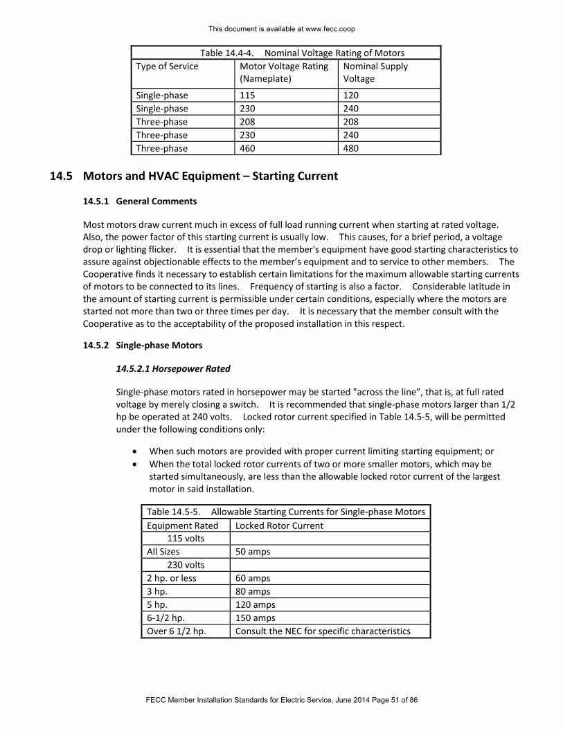
Table 14.4-4. Nominal Voltage Rating of Motors Type of Service Motor Voltage Rating
(Nameplate) Nominal Supply Voltage
Single-phase 115 120
Single-phase 230 240
Three-phase 208 208
Three-phase 230 240
Three-phase 460 480
14.5 Motors and HVAC Equipment – Starting Current
14.5.1 General Comments
Most motors draw current much in excess of full load running current when starting at rated voltage. Also, the power factor of this starting current is usually low. This causes, for a brief period, a voltage drop or lighting flicker. It is essential that the member's equipment have good starting characteristics to assure against objectionable effects to the member’s equipment and to service to other members. The Cooperative finds it necessary to establish certain limitations for the maximum allowable starting currents of motors to be connected to its lines. Frequency of starting is also a factor. Considerable latitude in the amount of starting current is permissible under certain conditions, especially where the motors are started not more than two or three times per day. It is necessary that the member consult with the Cooperative as to the acceptability of the proposed installation in this respect.
14.5.2 Single-phase Motors
14.5.2.1 Horsepower Rated
Single-phase motors rated in horsepower may be started "across the line”, that is, at full rated voltage by merely closing a switch. It is recommended that single-phase motors larger than 1/2 hp be operated at 240 volts. Locked rotor current specified in Table 14.5-5, will be permitted under the following conditions only:
When such motors are provided with proper current limiting starting equipment; or
When the total locked rotor currents of two or more smaller motors, which may be started simultaneously, are less than the allowable locked rotor current of the largest motor in said installation.
Table 14.5-5. Allowable Starting Currents for Single-phase Motors
Equipment Rated Locked Rotor Current 115 volts
All Sizes 50 amps
230 volts
2 hp. or less 60 amps
3 hp. 80 amps
5 hp. 120 amps
6-1/2 hp. 150 amps
Over 6 1/2 hp. Consult the NEC for specific characteristics
This document is available at www.fecc.coop
FECC Member Installation Standards for Electric Service, June 2014 Page 51 of 86
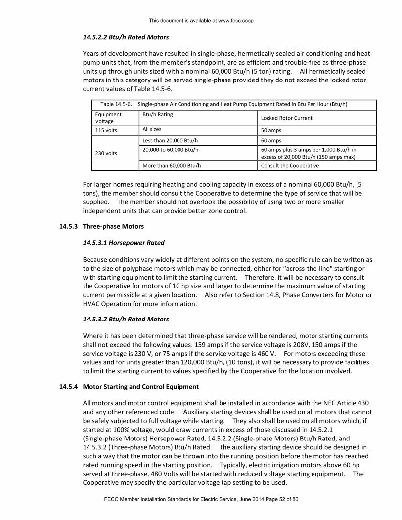
14.5.2.2 Btu/h Rated Motors
Years of development have resulted in single-phase, hermetically sealed air conditioning and heat pump units that, from the member's standpoint, are as efficient and trouble-free as three-phase units up through units sized with a nominal 60,000 Btu/h (5 ton) rating. All hermetically sealed motors in this category will be served single-phase provided they do not exceed the locked rotor current values of Table 14.5-6.
Table 14.5-6. Single-phase Air Conditioning and Heat Pump Equipment Rated In Btu Per Hour (Btu/h)
Equipment Voltage
Btu/h Rating Locked Rotor Current
115 volts All sizes 50 amps
230 volts
Less than 20,000 Btu/h 60 amps
20,000 to 60,000 Btu/h 60 amps plus 3 amps per 1,000 Btu/h in excess of 20,000 Btu/h (150 amps max)
More than 60,000 Btu/h Consult the Cooperative
For larger homes requiring heating and cooling capacity in excess of a nominal 60,000 Btu/h, (5 tons), the member should consult the Cooperative to determine the type of service that will be supplied. The member should not overlook the possibility of using two or more smaller independent units that can provide better zone control.
14.5.3 Three-phase Motors
14.5.3.1 Horsepower Rated
Because conditions vary widely at different points on the system, no specific rule can be written as to the size of polyphase motors which may be connected, either for “across-the-line" starting or with starting equipment to limit the starting current. Therefore, it will be necessary to consult the Cooperative for motors of 10 hp size and larger to determine the maximum value of starting current permissible at a given location. Also refer to Section 14.8, Phase Converters for Motor or HVAC Operation for more information.
14.5.3.2 Btu/h Rated Motors
Where it has been determined that three-phase service will be rendered, motor starting currents shall not exceed the following values: 159 amps if the service voltage is 208V, 150 amps if the service voltage is 230 V, or 75 amps if the service voltage is 460 V. For motors exceeding these values and for units greater than 120,000 Btu/h, (10 tons), it will be necessary to provide facilities to limit the starting current to values specified by the Cooperative for the location involved.
14.5.4 Motor Starting and Control Equipment
All motors and motor control equipment shall be installed in accordance with the NEC Article 430 and any other referenced code. Auxiliary starting devices shall be used on all motors that cannot be safely subjected to full voltage while starting. They also shall be used on all motors which, if started at 100% voltage, would draw currents in excess of those discussed in 14.5.2.1 (Single-phase Motors) Horsepower Rated, 14.5.2.2 (Single-phase Motors) Btu/h Rated, and 14.5.3.2 (Three-phase Motors) Btu/h Rated. The auxiliary starting device should be designed in such a way that the motor can be thrown into the running position before the motor has reached rated running speed in the starting position. Typically, electric irrigation motors above 60 hp served at three-phase, 480 Volts will be started with reduced voltage starting equipment. The Cooperative may specify the particular voltage tap setting to be used.
This document is available at www.fecc.coop
FECC Member Installation Standards for Electric Service, June 2014 Page 52 of 86
Motor starters, controllers, and adjustable speed drives can create harmonic disturbances that may have detrimental effects on the Cooperative's electric system and/or service to other members. Devices of this type shall meet IEEE Standard 519 at the point of common coupling with the Cooperative’s facilities. Voltage disturbances attributable to the use of these type devices shall be corrected without undue delay, at the member's expense, to the satisfaction of the Cooperative. Consult the Cooperative for information.
14.6 Critical Service Motor Operation
Where continuous operation of a motor is essential, the no-voltage release should have a time delay relay, which will prevent the opening of the circuit in the event of momentary voltage fluctuation. The Cooperative will assist the member in selection of an automatic starting device and any other device to hold motors on line during voltage disturbances.
14.7 Motor and HVAC Equipment Protection
14.7.1 Phase Reversal Protection
Reverse phase relays are required on three-phase elevator services (NEC Article 620) and it is strongly recommended that the member install them where accidental reversal of motor rotation would cause serious inconvenience, damage, or delay. The Cooperative shall not be responsible for any damages caused by phase reversal.
14.7.2 Over-current Protection
NEC Article 430 requires that adequate over current protection be provided in each phase on all motor installations. The member shall ensure complete protection against "single-phasing" on all three-phase motors. Over current protection in two phases is not adequate protection for this condition. Single phasing on the distribution system is normal and necessary at times for fault clearing and switching and occurs occasionally due to unforeseen circumstances. Motor protection is the responsibility of the member.
14.7.3 Single-Phase Protection Required
The Cooperative operates its three-phase distribution system with single-phase protective devices. These single-phase devices may open from time to time as a part of their normal operating function, which will cause a partial or complete loss of service voltage on one or more phases. In three-phase services, this is loss of one or two phases is commonly known as a ‘single phase’ condition. The Cooperative shall not be held responsible or liable for damage to the member's installation due to such causes as they are a normal and inherent operation of the distribution system. In addition, the partial or complete loss of one or more phases also may be caused by a failure of the member's equipment serving the motor. For these reasons, it is the member’s responsibility to follow the requirements of the NEC (National Electric Code) Article 430 pertaining to motor protection. The Code requires motors to be provided with three current overload units, one in each phase. In addition, it is also recommended that all polyphase motor installations be equipped with an automatic disconnecting device (sensing voltage loss) as added protection for single phasing conditions (partial or complete loss of one or more phases).
This document is available at www.fecc.coop
FECC Member Installation Standards for Electric Service, June 2014 Page 53 of 86
14.8 Phase Converters for Motor or HVAC Equipment Operation
The phase converter is used to provide a three-phase voltage from a single-phase source. Phase
converters can provide a reliable and economical alternative for members requiring three-phase power at
locations where three-phase facilities are not economically available. For reliable operation, the phase
converter must be matched with both the motor horsepower and the motor application. Because there
are several different types of phase converters, the Cooperative recommends that the member consult
with the phase converter manufacturer or a knowledgeable supplier to determine the proper converter
for the application. Devices of this type shall meet IEEE Standard 519 at the point of common coupling
with the Cooperative’s facilities. Voltage disturbances attributable to the use of these type devices shall
be corrected without undue delay, at the member's expense, to the satisfaction of the Cooperative.
Consult the Cooperative for information. The Cooperative shall be consulted prior to the installation of a
phase converter supplying load greater than 10 horsepower.
This document is available at www.fecc.coop
FECC Member Installation Standards for Electric Service, June 2014 Page 54 of 86
Section 15: Member’s Specialized Equipment
15.1 General Comments
The Cooperative highly recommends that the member, prior to purchase, submit to the Cooperative information and specifications of any special equipment discussed below that may cause power quality problems for the member, the Cooperative, or other Cooperative members.
The Cooperative will not connect electric service until all issues relating to possible power quality problems have been satisfactorily addressed by the member. See Section 16 for a discussion of the applicable power quality standards used by the Cooperative.
The Cooperative reserves the right to inspect and test any equipment connected to its lines and to require the member to provide nameplate data showing the voltage, phase, full-load amperes, maximum current, maximum kVA and such other information as may be necessary to determine the operating characteristics of the equipment.
15.2 Additional Electric Facilities
A member may desire or require additional facilities (such as emergency service, oversized transformer, separate transformer, dual service, etc.) to minimize voltage fluctuations or interference with other members, or to provide satisfactory operation of the member’s electric equipment. The Cooperative in cases, where practicable, will furnish such facilities, when the member agrees to pay in some manner the additional cost of such facilities. Consult the Cooperative for details.
15.3 Radio, Satellite, and Television Antennas
Antennas for radio, satellite, and/or television sets never shall be erected over, under, or in close proximity of either side of the Cooperative's power lines or other wires carrying electric current; nor shall they be constructed in such a place where they accidentally may fall into energized wires. Antenna lead-in and other wires shall not cross over and should not cross under Cooperative's electric conductors. Such location of the member's apparatus may result in serious accidents, damage to the equipment, or poor reception. Where proximity to electric power service conductors cannot be avoided, a 10-foot minimum clearance is required. The attachment of antenna systems to poles or service masts carrying the Cooperative's conductors is strictly prohibited. The Cooperative will remove such attachments upon discovery, and the responsible party will be billed for all removal costs.
15.4 Electric Welders, Furnaces, and Industrial Equipment
Electric welders, arc furnaces, and other high-power industrial equipment usually have such severe load characteristics that special attention shall be given to the service installation to prevent interference and impairment of service to the member and others. The Cooperative is prepared to assist the member in planning installations of these types of loads. It is essential in every case that the Cooperative be consulted when such installations are being planned and before commitment to purchase equipment, so that there will be ample time to determine the electrical supply requirements.
This document is available at www.fecc.coop
FECC Member Installation Standards for Electric Service, June 2014 Page 55 of 86
15.5 High-Power Electronic Equipment
Radio and television transmitters, medical imaging equipment, frequency converters, phase converters, or other types of high-power electronic equipment may cause power quality problems for the member using such equipment, or for other members in the area. In such cases, the member owning such equipment shall install and maintain devices or use wiring methods approved by the Cooperative for mitigation of the interference. The Cooperative may discontinue service to the member’s premises if such interference cannot be satisfactorily remediated.
Consult the Cooperative during the planning stage for service to any facilities utilizing high-power electronic equipment.
15.6 Member’s Capacitors and Other Reactive Power Equipment
It is desirable and important to maintain the power factor of any load as near unity as possible. Maintaining a high power factor may allow a reduction of conductor sizes and equipment capacities. This may suggest the installation of capacitors. Capacitors shall be applied more carefully than most types of electrical equipment in order that satisfactory operation and maintenance will result. When a member installs capacitors to improve the power factor, the member should provide, or at the request of Cooperative, the member shall provide automatic disconnecting of capacitors when the equipment causing the low power factor is not operating. Where large capacity motors are to be installed, consideration should be given to the use of synchronous type equipment.
This document is available at www.fecc.coop
FECC Member Installation Standards for Electric Service, June 2014 Page 56 of 86
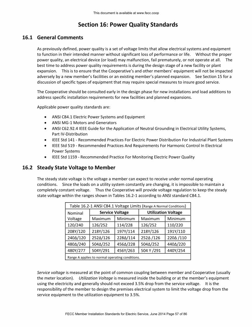
Section 16: Power Quality Standards
16.1 General Comments
As previously defined, power quality is a set of voltage limits that allow electrical systems and equipment to function in their intended manner without significant loss of performance or life. Without the proper power quality, an electrical device (or load) may malfunction, fail prematurely, or not operate at all. The best time to address power quality requirements is during the design stage of a new facility or plant expansion. This is to ensure that the Cooperative’s and other members’ equipment will not be impacted adversely by a new member’s facilities or an existing member’s planned expansion. See Section 15 for a discussion of specific types of equipment that may require special measures to insure good service.
The Cooperative should be consulted early in the design phase for new installations and load additions to address specific installation requirements for new facilities and planned expansions.
Applicable power quality standards are:
ANSI C84.1 Electric Power Systems and Equipment
ANSI MG-1 Motors and Generators
ANSI C62.92.4 IEEE Guide for the Application of Neutral Grounding in Electrical Utility Systems, Part IV-Distribution
IEEE Std 141 - Recommended Practices For Electric Power Distribution For Industrial Plant Systems
IEEE Std 519 - Recommended Practices And Requirements For Harmonic Control In Electrical Power Systems
IEEE Std 1159 - Recommended Practice For Monitoring Electric Power Quality
16.2 Steady State Voltage to Member
The steady state voltage is the voltage a member can expect to receive under normal operating conditions. Since the loads on a utility system constantly are changing, it is impossible to maintain a completely constant voltage. Thus the Cooperative will provide voltage regulation to keep the steady state voltage within the ranges shown in Tables 16.2-1 according to ANSI standard C84.1.
Table 16.2-1 ANSI C84.1 Voltage Limits (Range A Normal Conditions)
Nominal Voltage
Service Voltage Utilization Voltage
Maximum Minimum Maximum Minimum
120/240 126/252 114/228 126/252 110/220
208Y/120 218Y/126 197Y/114 218Y/126 191Y/110
240Δ/120 252Δ/126 228Δ/114 252Δ /126 220Δ /110
480Δ/240 504Δ/252 456Δ/228 504Δ/252 440Δ/220
480Y/277 504Y/291 456Y/263 504 Y /291 440Y/254
Range A applies to normal operating conditions.
Service voltage is measured at the point of common coupling between member and Cooperative (usually the meter location). Utilization Voltage is measured inside the building or at the member’s equipment using the electricity and generally should not exceed 3.5% drop from the service voltage. It is the responsibility of the member to design the premises electrical system to limit the voltage drop from the service equipment to the utilization equipment to 3.5%.
This document is available at www.fecc.coop
FECC Member Installation Standards for Electric Service, June 2014 Page 57 of 86
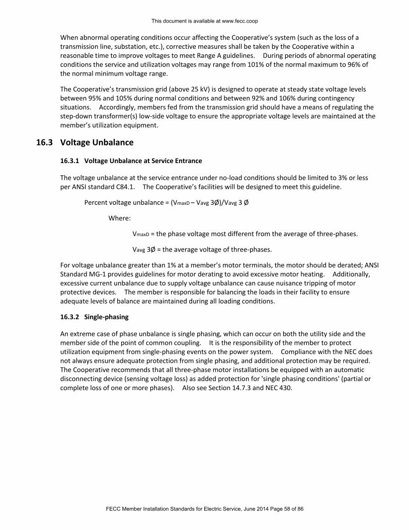
When abnormal operating conditions occur affecting the Cooperative’s system (such as the loss of a transmission line, substation, etc.), corrective measures shall be taken by the Cooperative within a reasonable time to improve voltages to meet Range A guidelines. During periods of abnormal operating conditions the service and utilization voltages may range from 101% of the normal maximum to 96% of the normal minimum voltage range.
The Cooperative’s transmission grid (above 25 kV) is designed to operate at steady state voltage levels between 95% and 105% during normal conditions and between 92% and 106% during contingency situations. Accordingly, members fed from the transmission grid should have a means of regulating the step-down transformer(s) low-side voltage to ensure the appropriate voltage levels are maintained at the member’s utilization equipment.
16.3 Voltage Unbalance
16.3.1 Voltage Unbalance at Service Entrance
The voltage unbalance at the service entrance under no-load conditions should be limited to 3% or less per ANSI standard C84.1. The Cooperative’s facilities will be designed to meet this guideline.
Percent voltage unbalance = (VmaxD – Vavg 3Ø)/Vavg 3 Ø
Where:
VmaxD = the phase voltage most different from the average of three-phases.
Vavg 3Ø = the average voltage of three-phases.
For voltage unbalance greater than 1% at a member’s motor terminals, the motor should be derated; ANSI Standard MG-1 provides guidelines for motor derating to avoid excessive motor heating. Additionally, excessive current unbalance due to supply voltage unbalance can cause nuisance tripping of motor protective devices. The member is responsible for balancing the loads in their facility to ensure adequate levels of balance are maintained during all loading conditions.
16.3.2 Single-phasing
An extreme case of phase unbalance is single phasing, which can occur on both the utility side and the member side of the point of common coupling. It is the responsibility of the member to protect utilization equipment from single-phasing events on the power system. Compliance with the NEC does not always ensure adequate protection from single phasing, and additional protection may be required. The Cooperative recommends that all three-phase motor installations be equipped with an automatic disconnecting device (sensing voltage loss) as added protection for 'single phasing conditions' (partial or complete loss of one or more phases). Also see Section 14.7.3 and NEC 430.
This document is available at www.fecc.coop
FECC Member Installation Standards for Electric Service, June 2014 Page 58 of 86
Section 17: Specification Drawings The Drawing Numbers on each specification in the following pages correspond to the related section in these
Standards. For example, Drawings 4.5-1 and 4.5-2 correspond with Section 4.5 in the narrative section of the
Standards.
Specification Drawings
4.5-1 Temporary Meter Pole (Overhead Builder's Service) Installation Specifications
4.5-2 Temporary Meter Pedestal (Underground Builder's Service) Installation Specifications
4.6-1 Meter Pole - Service Location Specifications
4.6-2 Meter Pedestal - Service Location Specifications
4.6-3 Meter Pedestal (Underground Source and Load) Installation Specifications
4.7-1 Mobile Home Park Central Metering Location Specifications
4.10-1 Overhead Irrigation Service (Meter & Equipment Rack) Installation Specifications
4.10-2 Underground Irrigation Service (Meter & Equipment Rack) Installation Specifications
7.1-1 Overhead Meter on Home or Building (Wall or Fascia Attachment) Installation Specifications
7.1-2 Overhead Meter on Home or Building (Service Mast Attachment) Installation Specifications
7.1-3 Meter Pole (Single-phase Underground Load Connection) Installation Specifications
7.1-4 Meter Pole (Single-phase Overhead Load Connection) Installation Specifications
7.1-5 Meter Pole (Three-phase Underground Load Connection) Installation Specifications
7.2-1 Overhead Meter on House - Service Location Specifications
8.6-1 Underground Service Conduit System Installation Specifications
8.6-2 Underground Meter on Home of Building Installation Specifications
8.6-3 Concrete Encased Conduit Specifications
8.6-4 Underground Meter on House - Service Location Specifications
8.7-1 Primary Conduit Trench Specifications
10.4-1 Pad Mount Transformer Location Specifications
10.4-2 Three Phase Transformer Pad Specifications
11.6-1 Overhead Multiple Meter Installation Specifications
11.6-2 Underground Multiple-Meter Installation Specifications
11.6-3 Factory-Assembled Multiple Meter Installation Specifications (Overhead or Underground)
11.8-1 Self-Contained Meter Wiring Diagrams up to 320A
11.8-2 Underground CT on Building (CT Cabinet) Installation Specifications (Over 320A)
11.8-3 Overhead CT on Building (CT Cabinet) Installation Specifications (Over 320A)
This document is available at www.fecc.coop
FECC Member Installation Standards for Electric Service, June 2014 Page 59 of 86
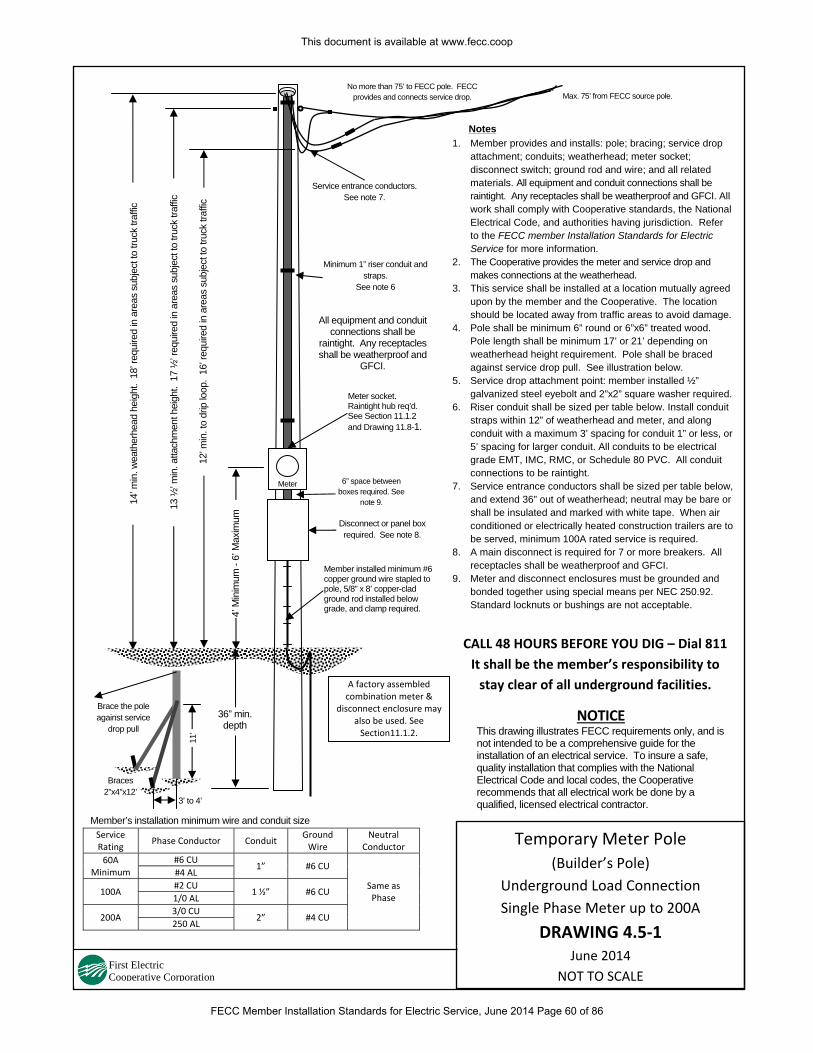
1. Member provides and installs: pole; bracing; service drop attachment; conduits; weatherhead; meter socket; disconnect switch; ground rod and wire; and all related materials. All equipment and conduit connections shall be raintight. Any receptacles shall be weatherproof and GFCI. All work shall comply with Cooperative standards, the National Electrical Code, and authorities having jurisdiction. Refer to the FECC member Installation Standards for Electric Service for more information.
2. The Cooperative provides the meter and service drop and makes connections at the weatherhead.
3. This service shall be installed at a location mutually agreed upon by the member and the Cooperative. The location should be located away from traffic areas to avoid damage.
4. Pole shall be minimum 6” round or 6”x6” treated wood. Pole length shall be minimum 17’ or 21’ depending on weatherhead height requirement. Pole shall be braced against service drop pull. See illustration below.
5. Service drop attachment point: member installed ½” galvanized steel eyebolt and 2”x2” square washer required.
6. Riser conduit shall be sized per table below. Install conduit straps within 12” of weatherhead and meter, and along conduit with a maximum 3’ spacing for conduit 1” or less, or5’ spacing for larger conduit. All conduits to be electrical grade EMT, IMC, RMC, or Schedule 80 PVC. All conduit connections to be raintight.
7. Service entrance conductors shall be sized per table below, and extend 36” out of weatherhead; neutral may be bare or shall be insulated and marked with white tape. When air conditioned or electrically heated construction trailers are to be served, minimum 100A rated service is required.
8. A main disconnect is required for 7 or more breakers. All receptacles shall be weatherproof and GFCI.
9. Meter and disconnect enclosures must be grounded and bonded together using special means per NEC 250.92. Standard locknuts or bushings are not acceptable.
Notes14
’ min
. wea
ther
head
hei
ght.
18’
requ
ired
in a
reas
sub
ject
to tr
uck
traffi
c
4’ M
inim
um -
6’ M
axim
um
CALL 48 HOURS BEFORE YOU DIG – Dial 811
It shall be the member’s responsibility to
stay clear of all underground facilities.
NOTICE This drawing illustrates FECC requirements only, and is not intended to be a comprehensive guide for the installation of an electrical service. To insure a safe, quality installation that complies with the National Electrical Code and local codes, the Cooperative recommends that all electrical work be done by a qualified, licensed electrical contractor.
Max. 75’ from FECC source pole.
Minimum 1” riser conduit and straps.
See note 6
Meter
Disconnect or panel box required. See note 8.
Member installed minimum #6 copper ground wire stapled to pole, 5/8” x 8’ copper-clad ground rod installed below grade, and clamp required.
6” space between boxes required. See
note 9.
No more than 75’ to FECC pole. FECC provides and connects service drop.
Service entrance conductors.See note 7.
Meter socket. Raintight hub req’d. See Section 11.1.2 and Drawing 11.8-1.
All equipment and conduit connections shall be
raintight. Any receptacles shall be weatherproof and
GFCI.
36” min. depth
12’ m
in. t
o dr
ip lo
op.
16’ r
equi
red
in a
reas
sub
ject
to tr
uck
traffi
c
13 ½
’ min
. atta
chm
ent h
eigh
t. 1
7 ½
’ req
uire
d in
are
as s
ubje
ct to
truc
k tra
ffic
Brace the pole against service
drop pull
3’ to 4’
Braces 2”x4”x12’
11’
First Electric Cooperative Corporation
Member’s installation minimum wire and conduit size Service Rating
Phase Conductor Conduit Ground Wire
Neutral Conductor
60A Minimum
#6 CU 1” #6 CU
Same as Phase
#4 AL
100A #2 CU
1 ½” #6 CU 1/0 AL
200A 3/0 CU
2” #4 CU 250 AL
A factory assembled combination meter &
disconnect enclosure may also be used. See Section11.1.2.
Temporary Meter Pole
(Builder’s Pole)
Underground Load Connection
Single Phase Meter up to 200A
DRAWING 4.5‐1 June 2014
NOT TO SCALE
This document is available at www.fecc.coop
FECC Member Installation Standards for Electric Service, June 2014 Page 60 of 86
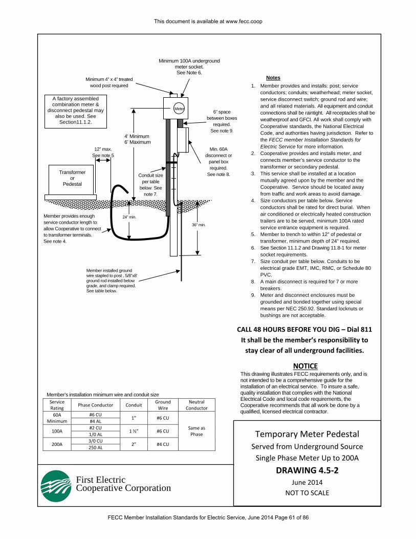
First Electric Cooperative Corporation
1. Member provides and installs: post; service conductors; conduits; weatherhead; meter socket, service disconnect switch; ground rod and wire; and all related materials. All equipment and conduit connections shall be raintight. All receptacles shall be weatherproof and GFCI. All work shall comply with Cooperative standards, the National Electrical Code, and authorities having jurisdiction. Refer to the FECC member Installation Standards for Electric Service for more information.
2. Cooperative provides and installs meter, and connects member’s service conductor to the transformer or secondary pedestal.
3. This service shall be installed at a location mutually agreed upon by the member and the Cooperative. Service should be located away from traffic and work areas to avoid damage.
4. Size conductors per table below. Service conductors shall be rated for direct burial. When air conditioned or electrically heated construction trailers are to be served, minimum 100A rated service entrance equipment is required.
5. Member to trench to within 12” of pedestal or transformer, minimum depth of 24” required.
6. See Section 11.1.2 and Drawing 11.8-1 for meter socket requirements.
7. Size conduit per table below. Conduits to be electrical grade EMT, IMC, RMC, or Schedule 80 PVC.
8. A main disconnect is required for 7 or more breakers.
9. Meter and disconnect enclosures must be grounded and bonded together using special means per NEC 250.92. Standard locknuts or bushings are not acceptable.
Notes
4’ Minimum 6’ Maximum
CALL 48 HOURS BEFORE YOU DIG – Dial 811
It shall be the member’s responsibility to
stay clear of all underground facilities.
Meter
Min. 60A disconnect or
panel box required.
See note 8.
6” space between boxes
required. See note 9.
Minimum 4” x 4” treated wood post required
Transformer or
Pedestal
24” min. Member provides enough service conductor length to allow Cooperative to connect to transformer terminals. See note 4.
36” min.
12” max. See note 5
Member installed ground wire stapled to post , 5/8”x8’ ground rod installed below grade, and clamp required. See table below.
NOTICE This drawing illustrates FECC requirements only, and is not intended to be a comprehensive guide for the installation of an electrical service. To insure a safe, quality installation that complies with the National Electrical Code and local code requirements, the Cooperative recommends that all work be done by a qualified, licensed electrical contractor.
Conduit size per table
below. See note 7.
Minimum 100A underground meter socket. See Note 6.
Member’s installation minimum wire and conduit size Service Rating
Phase Conductor Conduit Ground Wire
Neutral Conductor
60A Minimum
#6 CU 1” #6 CU
Same as Phase
#4 AL
100A #2 CU
1 ½” #6 CU 1/0 AL
200A 3/0 CU
2” #4 CU 250 AL
A factory assembled combination meter &
disconnect pedestal may also be used. See
Section11.1.2.
Temporary Meter Pedestal
Served from Underground Source
Single Phase Meter Up to 200A
DRAWING 4.5‐2 June 2014
NOT TO SCALE
This document is available at www.fecc.coop
FECC Member Installation Standards for Electric Service, June 2014 Page 61 of 86
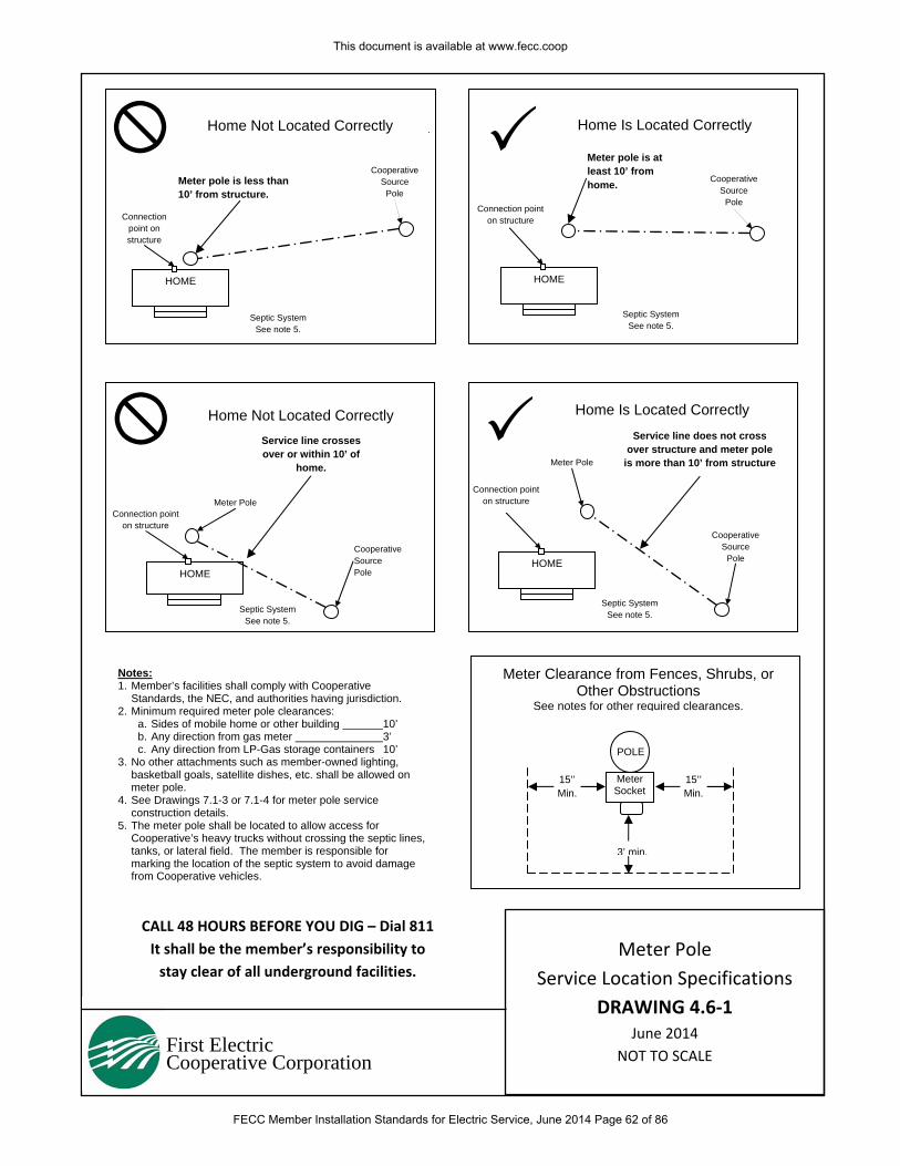
First Electric Cooperative Corporation
CALL 48 HOURS BEFORE YOU DIG – Dial 811
It shall be the member’s responsibility to
stay clear of all underground facilities.
Notes: 1. Member’s facilities shall comply with Cooperative
Standards, the NEC, and authorities having jurisdiction. 2. Minimum required meter pole clearances:
a. Sides of mobile home or other building 10’ b. Any direction from gas meter 3’ c. Any direction from LP-Gas storage containers 10’
3. No other attachments such as member-owned lighting, basketball goals, satellite dishes, etc. shall be allowed on meter pole.
4. See Drawings 7.1-3 or 7.1-4 for meter pole service construction details.
5. The meter pole shall be located to allow access for Cooperative’s heavy trucks without crossing the septic lines, tanks, or lateral field. The member is responsible for marking the location of the septic system to avoid damage from Cooperative vehicles.
Home Not Located Correctly
Meter Clearance from Fences, Shrubs, or Other Obstructions
See notes for other required clearances.
HOME
HOME HOME
CooperativeSource
Pole
Connection point on structure
Connection point on structure
Connection point on structure
Meter Pole
HOME
Connection point on structure
Meter pole is less than 10’ from structure.
Meter pole is at least 10’ from home.
Cooperative Source
Pole
Cooperative Source Pole
Cooperative Source
Pole
Service line does not cross over structure and meter pole
is more than 10’ from structure
3’ min.
POLE
Meter Socket
Service line crosses over or within 10’ of
home.
Home Is Located Correctly
Home Not Located Correctly Home Is Located Correctly
Meter Pole
15’’ Min.
15’’Min.
Septic System See note 5.
Septic System See note 5.
Septic System See note 5.
Septic System See note 5.
Meter Pole
Service Location Specifications
DRAWING 4.6‐1 June 2014
NOT TO SCALE
This document is available at www.fecc.coop
FECC Member Installation Standards for Electric Service, June 2014 Page 62 of 86
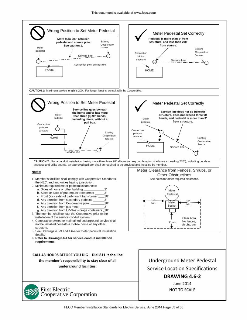
More than 200’ between pedestal and source pole.
See caution 1.
Service line goes beneath the home and/or has more than three (3) 90° bends,
including risers, without a pull box.
First Electric Cooperative Corporation
CAUTION 1: Maximum service length is 200’. For longer lengths, consult with the Cooperative.
Notes: 1. Member’s facilities shall comply with Cooperative Standards,
the NEC, and authorities having jurisdiction. 2. Minimum required meter pedestal clearances:
a. Sides of home or other building 3’ b. Sides or back of pad-mount transformer 3’ c. Front (lock side) of pad-mount transformer 10’ d. Any direction from secondary pedestal 3’ e. Any direction from Cooperative pole 10’ f. Any direction from gas meter 3’ g. Any direction from LP-Gas storage containers 10’
3. The member shall contact the Cooperative prior to the installation of the service conduit system.
4. Cooperative owned or maintained underground service shall not be installed beneath a mobile home or any other structure.
5. See Drawings 4.6-3 and 4.6-4 for meter pedestal installation details.
6. Refer to Drawing 8.6-1 for service conduit installation requirements.
Wrong Position to Set Meter Pedestal Meter Pedestal Set Correctly
HOME
HOME
HOME
Existing Cooperative Source
Connection point on structure
Connection point on structure
Connection point on structure
Meter pedestal
M
HOME
Connection point on structure
Meter pedestal
Existing Cooperative Source
Existing Cooperative
Source Existing Cooperative Source
Service line
CALL 48 HOURS BEFORE YOU DIG – Dial 811 It shall be
the member’s responsibility to stay clear of all
underground facilities.
15’’ Min.
15’’ Min.
3’ min.
Meter Pedestal
Meter Socket
CAUTION 2: For a conduit installation having more than three 90⁰ elbows (or any combination of elbows exceeding 270⁰), including bends at pedestal and utility source, an approved pull box shall be required to be provided and installed by member.
Meter Pedestal Set Correctly Wrong Position to Set Meter Pedestal
Pedestal is more than 3’ from structure, and less than 200’
from source.
Service line
Service line
Service line
Service line does not go beneath structure, does not exceed three 90 bends, and pedestal is more than 3’
from structure.
Meter Clearance from Fences, Shrubs, or Other Obstructions
See notes for other required clearance.
Meter pedestal
Clear Area No fences, shrubs, etc.
Underground Meter Pedestal
Service Location Specifications
DRAWING 4.6‐2 June 2014
NOT TO SCALE
This document is available at www.fecc.coop
FECC Member Installation Standards for Electric Service, June 2014 Page 63 of 86
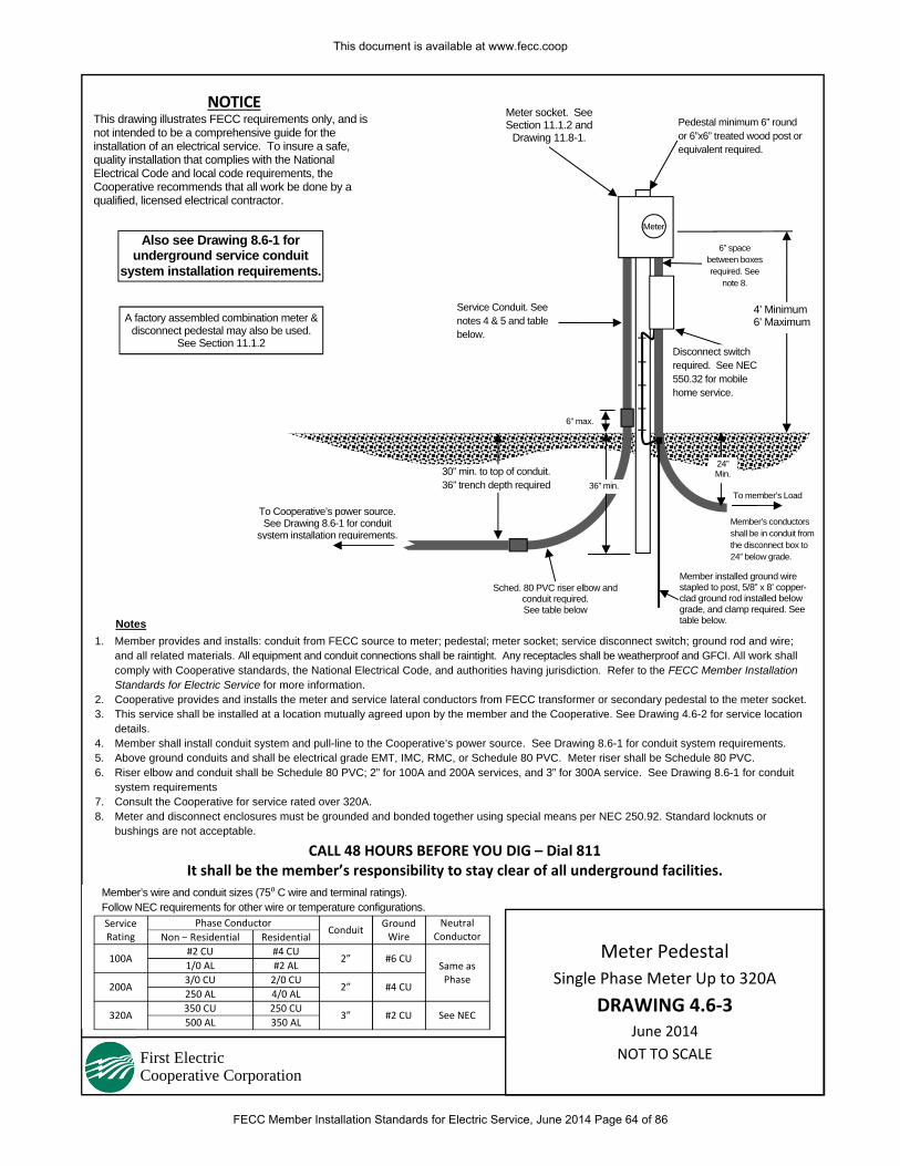
First Electric Cooperative Corporation
1. Member provides and installs: conduit from FECC source to meter; pedestal; meter socket; service disconnect switch; ground rod and wire; and all related materials. All equipment and conduit connections shall be raintight. Any receptacles shall be weatherproof and GFCI. All work shall comply with Cooperative standards, the National Electrical Code, and authorities having jurisdiction. Refer to the FECC Member Installation Standards for Electric Service for more information.
2. Cooperative provides and installs the meter and service lateral conductors from FECC transformer or secondary pedestal to the meter socket.3. This service shall be installed at a location mutually agreed upon by the member and the Cooperative. See Drawing 4.6-2 for service location
details. 4. Member shall install conduit system and pull-line to the Cooperative’s power source. See Drawing 8.6-1 for conduit system requirements. 5. Above ground conduits and shall be electrical grade EMT, IMC, RMC, or Schedule 80 PVC. Meter riser shall be Schedule 80 PVC. 6. Riser elbow and conduit shall be Schedule 80 PVC; 2” for 100A and 200A services, and 3” for 300A service. See Drawing 8.6-1 for conduit
system requirements 7. Consult the Cooperative for service rated over 320A. 8. Meter and disconnect enclosures must be grounded and bonded together using special means per NEC 250.92. Standard locknuts or
bushings are not acceptable.
Member’s wire and conduit sizes (75⁰ C wire and terminal ratings). Follow NEC requirements for other wire or temperature configurations. Service Rating
Phase Conductor Conduit
Ground Wire
Neutral Conductor Non – Residential Residential
100A #2 CU #4 CU
2” #6 CU Same as Phase
1/0 AL #2 AL
200A 3/0 CU 2/0 CU
2” #4 CU 250 AL 4/0 AL
320A 350 CU 250 CU
3” #2 CU See NEC 500 AL 350 AL
CALL 48 HOURS BEFORE YOU DIG – Dial 811 It shall be the member’s responsibility to stay clear of all underground facilities.
NOTICE This drawing illustrates FECC requirements only, and is not intended to be a comprehensive guide for the installation of an electrical service. To insure a safe, quality installation that complies with the National Electrical Code and local code requirements, the Cooperative recommends that all work be done by a qualified, licensed electrical contractor.
Notes
Member installed ground wire stapled to post, 5/8” x 8’ copper-clad ground rod installed below grade, and clamp required. See table below.
To Cooperative’s power source. See Drawing 8.6-1 for conduit
system installation requirements.
Pedestal minimum 6” round or 6”x6” treated wood post or equivalent required.
Sched. 80 PVC riser elbow and conduit required. See table below
6” max.
Meter socket. See Section 11.1.2 and
Drawing 11.8-1.
30” min. to top of conduit. 36” trench depth required
4’ Minimum 6’ Maximum
Member’s conductors shall be in conduit from the disconnect box to 24” below grade.
36” min.
Service Conduit. See notes 4 & 5 and table below.
24” Min.
Also see Drawing 8.6-1 for underground service conduit
system installation requirements.
To member’s Load
A factory assembled combination meter & disconnect pedestal may also be used.
See Section 11.1.2
Meter Pedestal
Single Phase Meter Up to 320A
DRAWING 4.6‐3 June 2014
NOT TO SCALE
Meter
6” space between boxes required. See
note 8.
Disconnect switch required. See NEC 550.32 for mobile home service.
This document is available at www.fecc.coop
FECC Member Installation Standards for Electric Service, June 2014 Page 64 of 86
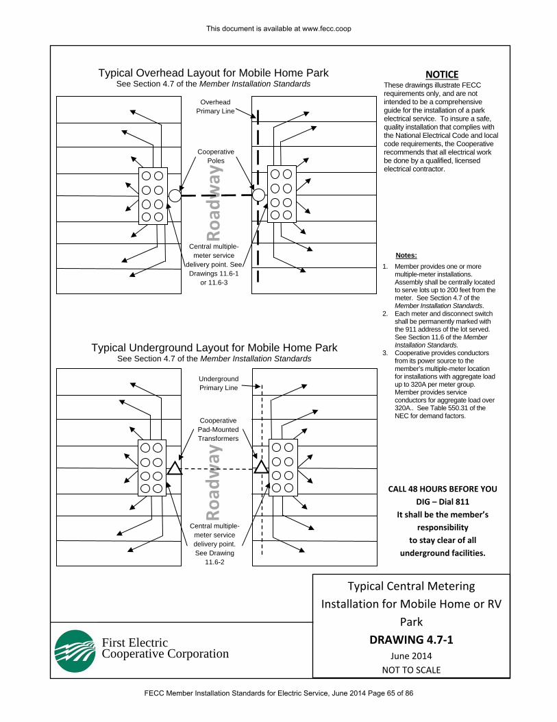
Road
way
Road
way
First Electric Cooperative Corporation
Typical Overhead Layout for Mobile Home Park See Section 4.7 of the Member Installation Standards
Typical Underground Layout for Mobile Home Park See Section 4.7 of the Member Installation Standards
Overhead Primary Line
Underground Primary Line
Cooperative Poles
Cooperative Pad-Mounted Transformers
Central multiple-meter service
delivery point. See Drawings 11.6-1
or 11.6-3
Central multiple-meter service delivery point. See Drawing
11.6-2
1. Member provides one or more multiple-meter installations. Assembly shall be centrally located to serve lots up to 200 feet from the meter. See Section 4.7 of the Member Installation Standards.
2. Each meter and disconnect switch shall be permanently marked with the 911 address of the lot served. See Section 11.6 of the Member Installation Standards.
3. Cooperative provides conductors from its power source to the member’s multiple-meter location for installations with aggregate load up to 320A per meter group. Member provides service conductors for aggregate load over 320A.. See Table 550.31 of the NEC for demand factors.
CALL 48 HOURS BEFORE YOU
DIG – Dial 811
It shall be the member’s
responsibility
to stay clear of all
underground facilities.
NOTICE These drawings illustrate FECC requirements only, and are not intended to be a comprehensive guide for the installation of a park electrical service. To insure a safe, quality installation that complies with the National Electrical Code and local code requirements, the Cooperative recommends that all electrical work be done by a qualified, licensed electrical contractor.
Notes:
Typical Central Metering
Installation for Mobile Home or RV
Park
DRAWING 4.7‐1 June 2014
NOT TO SCALE
This document is available at www.fecc.coop
FECC Member Installation Standards for Electric Service, June 2014 Page 65 of 86
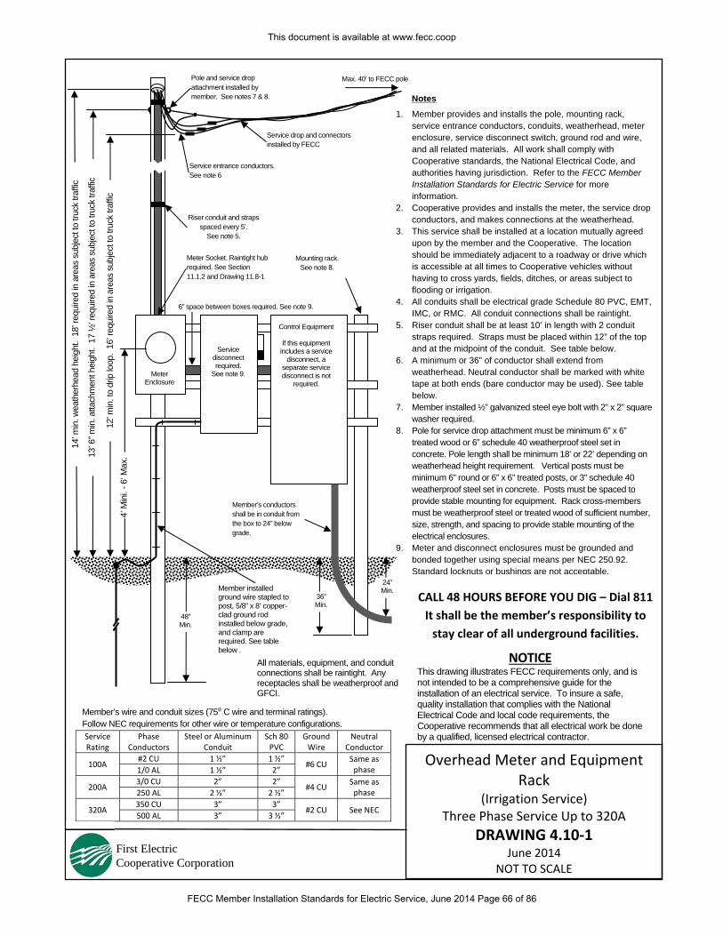
First Electric Cooperative Corporation
1. Member provides and installs the pole, mounting rack, service entrance conductors, conduits, weatherhead, meter enclosure, service disconnect switch, ground rod and wire, and all related materials. All work shall comply with Cooperative standards, the National Electrical Code, and authorities having jurisdiction. Refer to the FECC Member Installation Standards for Electric Service for more information.
2. Cooperative provides and installs the meter, the service drop conductors, and makes connections at the weatherhead.
3. This service shall be installed at a location mutually agreed upon by the member and the Cooperative. The location should be immediately adjacent to a roadway or drive which is accessible at all times to Cooperative vehicles without having to cross yards, fields, ditches, or areas subject to flooding or irrigation.
4. All conduits shall be electrical grade Schedule 80 PVC, EMT, IMC, or RMC. All conduit connections shall be raintight.
5. Riser conduit shall be at least 10’ in length with 2 conduit straps required. Straps must be placed within 12” of the top and at the midpoint of the conduit. See table below.
6. A minimum or 36” of conductor shall extend from weatherhead. Neutral conductor shall be marked with white tape at both ends (bare conductor may be used). See table below.
7. Member installed ½” galvanized steel eye bolt with 2” x 2” square washer required.
8. Pole for service drop attachment must be minimum 6” x 6” treated wood or 6” schedule 40 weatherproof steel set in concrete. Pole length shall be minimum 18’ or 22’ depending on weatherhead height requirement. Vertical posts must be minimum 6” round or 6” x 6” treated posts, or 3” schedule 40 weatherproof steel set in concrete. Posts must be spaced to provide stable mounting for equipment. Rack cross-members must be weatherproof steel or treated wood of sufficient number, size, strength, and spacing to provide stable mounting of the electrical enclosures.
9. Meter and disconnect enclosures must be grounded and bonded together using special means per NEC 250.92. Standard locknuts or bushings are not acceptable.
CALL 48 HOURS BEFORE YOU DIG – Dial 811
It shall be the member’s responsibility to
stay clear of all underground facilities.
4’ M
ini.
- 6’ M
ax.
All materials, equipment, and conduit connections shall be raintight. Any receptacles shall be weatherproof and GFCI.
Meter Enclosure
Service disconnect required.
See note 9.
Control Equipment
If this equipment includes a service
disconnect, a separate service disconnect is not
required.
Member installed ground wire stapled to post, 5/8” x 8’ copper-clad ground rod installed below grade, and clamp are required. See table below .
36” Min.
48” Min.
Riser conduit and straps spaced every 5’.
See note 5.
Mounting rack. See note 8.
Notes
Meter Socket. Raintight hub required. See Section 11.1.2 and Drawing 11.8-1
6” space between boxes required. See note 9.
Service drop and connectors installed by FECC
Pole and service drop attachment installed by member. See notes 7 & 8.
Max. 40’ to FECC pole
NOTICE This drawing illustrates FECC requirements only, and is not intended to be a comprehensive guide for the installation of an electrical service. To insure a safe, quality installation that complies with the National Electrical Code and local code requirements, the Cooperative recommends that all electrical work be done by a qualified, licensed electrical contractor.
Member’s conductors shall be in conduit from the box to 24” below grade.
Service entrance conductors. See note 6
24” Min.
14’ m
in. w
eath
erhe
ad h
eigh
t. 1
8’ re
quire
d in
are
as s
ubje
ct to
truc
k tra
ffic
13’ 6
” min
. atta
chm
ent h
eigh
t. 1
7 ½
’ req
uire
d in
are
as s
ubje
ct to
truc
k tra
ffic
12’ m
in. t
o dr
ip lo
op.
16’ r
equi
red
in a
reas
sub
ject
to tr
uck
traffi
c
Member’s wire and conduit sizes (75⁰ C wire and terminal ratings). Follow NEC requirements for other wire or temperature configurations. Service Rating
Phase Conductors
Steel or Aluminum Conduit
Sch 80 PVC
Ground Wire
Neutral Conductor
100A #2 CU 1 ½” 1 ½”
#6 CU Same as phase 1/0 AL 1 ½” 2”
200A 3/0 CU 2” 2”
#4 CU Same as phase 250 AL 2 ½” 2 ½”
320A 350 CU 3” 3”
#2 CU See NEC 500 AL 3” 3 ½”
Overhead Meter and Equipment Rack
(Irrigation Service) Three Phase Service Up to 320A
DRAWING 4.10‐1 June 2014
NOT TO SCALE
This document is available at www.fecc.coop
FECC Member Installation Standards for Electric Service, June 2014 Page 66 of 86
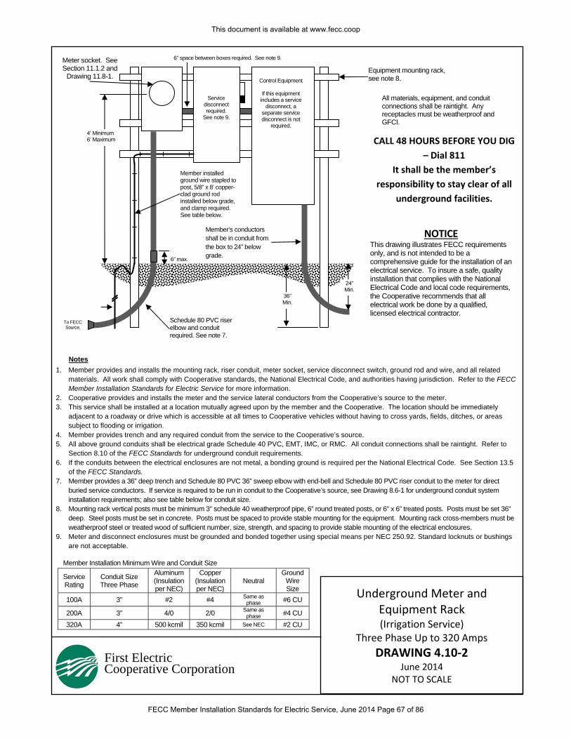
First Electric Cooperative Corporation
1. Member provides and installs the mounting rack, riser conduit, meter socket, service disconnect switch, ground rod and wire, and all related materials. All work shall comply with Cooperative standards, the National Electrical Code, and authorities having jurisdiction. Refer to the FECC Member Installation Standards for Electric Service for more information.
2. Cooperative provides and installs the meter and the service lateral conductors from the Cooperative’s source to the meter. 3. This service shall be installed at a location mutually agreed upon by the member and the Cooperative. The location should be immediately
adjacent to a roadway or drive which is accessible at all times to Cooperative vehicles without having to cross yards, fields, ditches, or areas subject to flooding or irrigation.
4. Member provides trench and any required conduit from the service to the Cooperative’s source. 5. All above ground conduits shall be electrical grade Schedule 40 PVC, EMT, IMC, or RMC. All conduit connections shall be raintight. Refer to
Section 8.10 of the FECC Standards for underground conduit requirements. 6. If the conduits between the electrical enclosures are not metal, a bonding ground is required per the National Electrical Code. See Section 13.5
of the FECC Standards. 7. Member provides a 36” deep trench and Schedule 80 PVC 36” sweep elbow with end-bell and Schedule 80 PVC riser conduit to the meter for direct
buried service conductors. If service is required to be run in conduit to the Cooperative’s source, see Drawing 8.6-1 for underground conduit system installation requirements; also see table below for conduit size.
8. Mounting rack vertical posts must be minimum 3” schedule 40 weatherproof pipe, 6” round treated posts, or 6” x 6” treated posts. Posts must be set 36” deep. Steel posts must be set in concrete. Posts must be spaced to provide stable mounting for the equipment. Mounting rack cross-members must be weatherproof steel or treated wood of sufficient number, size, strength, and spacing to provide stable mounting of the electrical enclosures.
9. Meter and disconnect enclosures must be grounded and bonded together using special means per NEC 250.92. Standard locknuts or bushings are not acceptable.
CALL 48 HOURS BEFORE YOU DIG
– Dial 811
It shall be the member’s
responsibility to stay clear of all
underground facilities.
Notes
Service disconnect required.
See note 9.
Schedule 80 PVC riser elbow and conduit required. See note 7.
Member installed ground wire stapled to post, 5/8” x 8’ copper-clad ground rod installed below grade, and clamp required. See table below.
36” Min.
To FECC Source.
4’ Minimum 6’ Maximum
Equipment mounting rack, see note 8.
All materials, equipment, and conduit connections shall be raintight. Any receptacles must be weatherproof and GFCI.
6” space between boxes required. See note 9.
NOTICE This drawing illustrates FECC requirements only, and is not intended to be a comprehensive guide for the installation of an electrical service. To insure a safe, quality installation that complies with the National Electrical Code and local code requirements, the Cooperative recommends that all electrical work be done by a qualified, licensed electrical contractor.
Member’s conductors shall be in conduit from the box to 24” below grade.
24” Min.
Meter socket. See Section 11.1.2 and
Drawing 11.8-1.
Member Installation Minimum Wire and Conduit Size
Service Rating
Conduit Size Three Phase
Aluminum (Insulation per NEC)
Copper (Insulation per NEC)
Neutral Ground
Wire Size
100A 3” #2 #4 Same as phase #6 CU
200A 3” 4/0 2/0 Same as phase #4 CU
320A 4” 500 kcmil 350 kcmil See NEC #2 CU
6” max.
Control Equipment
If this equipment includes a service
disconnect, a separate service disconnect is not
required.
Underground Meter and Equipment Rack (Irrigation Service)
Three Phase Up to 320 Amps
DRAWING 4.10‐2 June 2014
NOT TO SCALE
This document is available at www.fecc.coop
FECC Member Installation Standards for Electric Service, June 2014 Page 67 of 86
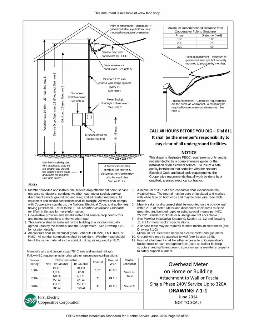
First Electric Cooperative Corporation
1. Member provides and installs: the service drop attachment point; service entrance conductors; conduits; weatherhead; meter socket; service disconnect switch; ground rod and wire; and all related materials. All equipment and conduit connections shall be raintight. All work shall comply with Cooperative standards, the National Electrical Code, and authorities having jurisdiction. Refer to the FECC Member Installation Standards for Electric Service for more information.
2. Cooperative provides and installs meter and service drop conductors and makes connections at the weatherhead.
3. This service shall be installed on the building at a location mutually agreed upon by the member and the Cooperative. See Drawing 7.2-1 for location details.
4. All conduits shall be electrical grade Schedule 80 PVC, EMT, IMC, or RMC. All conduit connections shall be raintight. Weatherhead should be of the same material as the conduit. Strap as required by NEC.
5. A minimum of 3'-0" of each conductor shall extend from the weatherhead. The neutral may be bare or insulated and marked with white tape on both ends and may be bare wire. See table below
6. Main breaker or disconnect shall be mounted on the outside wall within 2'-0" of meter. Meter and disconnect enclosures must be grounded and bonded together using special means per NEC 250.92. Standard locknuts or bushings are not acceptable.
7. See Member Installation Standards Section 11.1.2 and Drawing 11.8-1 for meter socket specifications.
8. A service mast may be required to meet minimum clearances (see Drawing 7.1-2).
9. Minimum 3 ft. clearance between electric meter and gas meter. 10. Ground wire may be attached to wall (see Section 13.5). 11. Point of attachment shall be either accessible to Cooperative's
bucket truck or have enough surface (such as wall or building structure) and sufficient ground space on same member's property to safely support a ladder.
Maximum Recommended Distance from Cooperative Pole to Structure Amps Distance (feet) 100 100 200 75 320 40
Point of attachment – minimum ½” galvanized steel eye bolt securely mounted to structure by member.
Minimum 1 ½” riser conduit with straps spaced
every 5’. See note 4
Notes
CALL 48 HOURS BEFORE YOU DIG – Dial 811
It shall be the member’s responsibility to
stay clear of all underground facilities.
Fascia Attachment - Clearance requirements are the same as wall mount. A mast may be required to meet minimum clearances. See note 8.
Member installed ground wire attached to wall, 5/8” x 8’ copper-clad ground rod installed below grade, and clamp are required. See table below .
4’ m
in -
6’ m
ax.
Disconnect switch required.
See note 6. Meter Socket. Raintight hub required.
See note 7.
Serv
ice
Dro
p At
tach
men
t 13
½’ r
equi
red.
See
not
e 8
Drip
Loo
p 12
’ min
. Se
e no
te 8
Point of attachment – minimum ½” galvanized steel eye bolt securely mounted to structure by member.
NOTICE This drawing illustrates FECC requirements only, and is not intended to be a comprehensive guide for the installation of an electrical service. To insure a safe, quality installation that complies with the National Electrical Code and local code requirements, the Cooperative recommends that all work be done by a qualified, licensed electrical contractor.
6” space between boxes required.
Service entrance conductors. See note 5.
Service drop and connectors by FECC
Wea
ther
head
14’
min
. – 2
1’ m
ax. S
ee n
ote
8
A factory assembled combination meter &
disconnect enclosure may also be used. See Section11.1.2.
Member’s wire and conduit sizes (75⁰ C wire and terminal ratings). Follow NEC requirements for other wire or temperature configurations. Service Rating
Phase Conductor Conduit
Ground Wire
Neutral Conductor Non – Residential Residential
100A #2 CU #4 CU
1 ½” #6 CU Same as Phase
1/0 AL #2 AL
200A 3/0 CU 2/0 CU
2” #4 CU 250 AL 4/0 AL
320A 350 CU 250 CU
3” #2 CU See NEC 500 AL 350 AL
Overhead Meter on Home or Building
Attachment to Wall or Fascia Single Phase 240V Service Up to 320A
DRAWING 7.1‐1 June 2014
NOT TO SCALE
This document is available at www.fecc.coop
FECC Member Installation Standards for Electric Service, June 2014 Page 68 of 86
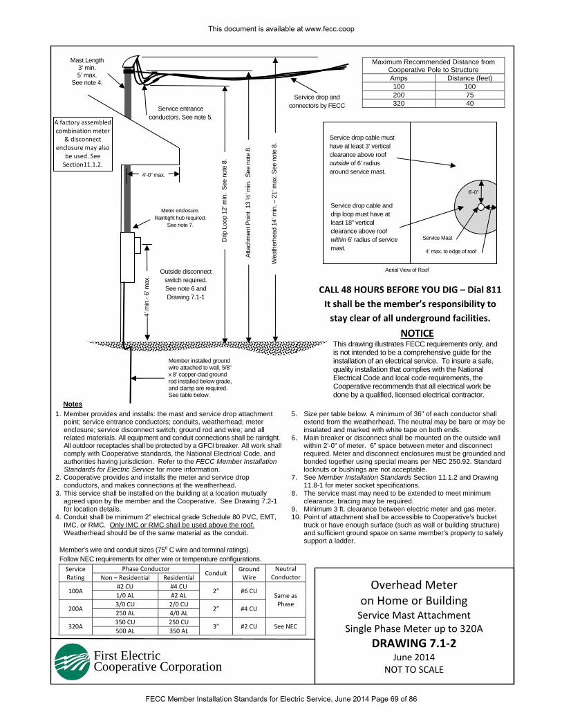
First Electric Cooperative Corporation
1. Member provides and installs: the mast and service drop attachment point; service entrance conductors; conduits, weatherhead; meter enclosure; service disconnect switch; ground rod and wire; and all related materials. All equipment and conduit connections shall be raintight. All outdoor receptacles shall be protected by a GFCI breaker. All work shall comply with Cooperative standards, the National Electrical Code, and authorities having jurisdiction. Refer to the FECC Member Installation Standards for Electric Service for more information.
2. Cooperative provides and installs the meter and service drop conductors, and makes connections at the weatherhead.
3. This service shall be installed on the building at a location mutually agreed upon by the member and the Cooperative. See Drawing 7.2-1 for location details.
4. Conduit shall be minimum 2” electrical grade Schedule 80 PVC, EMT, IMC, or RMC. Only IMC or RMC shall be used above the roof. Weatherhead should be of the same material as the conduit.
5. Size per table below. A minimum of 36" of each conductor shall extend from the weatherhead. The neutral may be bare or may be insulated and marked with white tape on both ends.
6. Main breaker or disconnect shall be mounted on the outside wall within 2'-0" of meter. 6” space between meter and disconnect required. Meter and disconnect enclosures must be grounded and bonded together using special means per NEC 250.92. Standard locknuts or bushings are not acceptable.
7. See Member Installation Standards Section 11.1.2 and Drawing 11.8-1 for meter socket specifications.
8. The service mast may need to be extended to meet minimum clearance; bracing may be required.
9. Minimum 3 ft. clearance between electric meter and gas meter. 10. Point of attachment shall be accessible to Cooperative's bucket
truck or have enough surface (such as wall or building structure) and sufficient ground space on same member's property to safely support a ladder.
Maximum Recommended Distance from Cooperative Pole to Structure Amps Distance (feet) 100 100 200 75 320 40
Notes
CALL 48 HOURS BEFORE YOU DIG – Dial 811
It shall be the member’s responsibility to
stay clear of all underground facilities.
NOTICE This drawing illustrates FECC requirements only, and is not intended to be a comprehensive guide for the installation of an electrical service. To insure a safe, quality installation that complies with the National Electrical Code and local code requirements, the Cooperative recommends that all electrical work be done by a qualified, licensed electrical contractor.
Member installed ground wire attached to wall, 5/8” x 8’ copper-clad ground rod installed below grade, and clamp are required. See table below.
4’ m
in -
6’ m
ax. Outside disconnect
switch required. See note 6 and Drawing 7.1-1
Wea
ther
head
14’
min
. – 2
1’ m
ax. S
ee n
ote
8.
Drip
Loo
p 12
’ min
. Se
e no
te 8
.
Mast Length 3’ min. 5’ max.
See note 4.
Service drop cable must have at least 3’ vertical clearance above roof outside of 6’ radius around service mast.
Service drop cable and drip loop must have at least 18” vertical clearance above roof within 6’ radius of service mast.
4’-0” max.
6’-0”
4’ max. to edge of roof
Service Mast
Aerial View of Roof
Meter enclosure. Raintight hub required.
See note 7.
Service entrance conductors. See note 5.
Service drop and connectors by FECC
Atta
chm
ent P
oint
13
½’ m
in.
See
note
8.
Member’s wire and conduit sizes (75⁰ C wire and terminal ratings). Follow NEC requirements for other wire or temperature configurations. Service Rating
Phase Conductor Conduit
Ground Wire
Neutral Conductor Non – Residential Residential
100A #2 CU #4 CU
2” #6 CU Same as Phase
1/0 AL #2 AL
200A 3/0 CU 2/0 CU
2” #4 CU 250 AL 4/0 AL
320A 350 CU 250 CU
3” #2 CU See NEC 500 AL 350 AL
A factory assembled combination meter
& disconnect enclosure may also
be used. See Section11.1.2.
Overhead Meter on Home or Building Service Mast Attachment
Single Phase Meter up to 320A
DRAWING 7.1‐2 June 2014
NOT TO SCALE
This document is available at www.fecc.coop
FECC Member Installation Standards for Electric Service, June 2014 Page 69 of 86
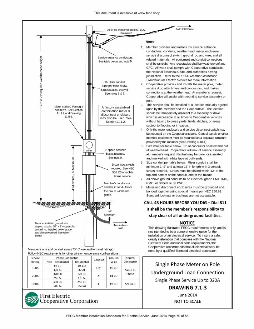
First Electric Cooperative Corporation
1. Member provides and installs the service entrance conductors, conduits, weatherhead, meter enclosure, service disconnect switch, ground rod and wire, and all related materials. All equipment and conduit connections shall be raintight. Any receptacles shall be weatherproof and GFCI. All work shall comply with Cooperative standards, the National Electrical Code, and authorities having jurisdiction. Refer to the FECC Member Installation Standards for Electric Service for more information.
2. Cooperative provides and installs the meter pole, meter, service drop attachment and conductors, and makes connections at the weatherhead. At member’s request, Cooperative will assist with mounting service assembly on pole.
3. This service shall be installed at a location mutually agreed upon by the member and the Cooperative. The location should be immediately adjacent to a roadway or drive which is accessible at all times to Cooperative vehicles without having to cross yards, fields, ditches, or areas subject to flooding or irrigation.
4. Only the meter enclosure and service disconnect switch may be mounted on the Cooperative’s pole. Control panels or other member equipment must be mounted on a separate structure provided by the member (see Drawing 4.10-1).
5. Size wire per table below. 36” of conductor shall extend out of weatherhead. Cooperative will mount service assembly at member’s request. Neutral may be bare, or insulated and marked with white tape at both ends.
6. Size conduit per table below. Riser conduit shall be minimum 1 ½” and at least 15’ in length with 3 conduit straps required. Straps must be placed within 12” of the top and bottom of the conduit, and at the middle.
7. All above-ground conduits to be electrical grade EMT, IMC, RMC, or Schedule 80 PVC.
8. Meter and disconnect enclosures must be grounded and bonded together using special means per NEC 250.92. Standard locknuts or bushings are not acceptable.
Notes20
’ to
21’ r
equi
red
wea
ther
head
hei
ght
4’ M
inim
um -
6’ M
axim
um
CALL 48 HOURS BEFORE YOU DIG – Dial 811
It shall be the member’s responsibility to
stay clear of all underground facilities.
NOTICE This drawing illustrates FECC requirements only, and is not intended to be a comprehensive guide for the installation of an electrical service. To insure a safe, quality installation that complies with the National Electrical Code and local code requirements, the Cooperative recommends that all electrical work be done by a qualified, licensed electrical contractor.
To FECC Source
15’ Riser conduit. Size per table below.
Straps spaced every 5’.See notes 6 & 7.
Meter
Disconnect switch required. See NEC 550.32 for mobile
home service.
Member installed ground wire stapled to pole, 5/8” x 8’ copper-clad ground rod installed below grade, and clamp required. See table below.
6” space between boxes required.
See note 8.
30-6 Pole and service drop by FECC. See note 2.
Service entrance conductors. See table below and note 5.
Meter socket. Raintight hub req’d. See Section
11.1.2 and Drawing 11.8-1.
A factory assembled combination meter & disconnect enclosure
may also be used. See Section11.1.2.
Member’s conductors shall be in conduit from the box to 24” below grade.
24” Minimum
To member’s Load
Member’s wire and conduit sizes (75⁰ C wire and terminal ratings). Follow NEC requirements for other wire or temperature configurations. Service Rating
Phase Conductor Conduit
Ground Wire
Neutral Conductor Non – Residential Residential
100A #2 CU #4 CU
1 ½” #6 CU Same as Phase
1/0 AL #2 AL
200A 3/0 CU 2/0 CU
2” #4 CU 250 AL 4/0 AL
320A 350 CU 250 CU
3” #2 CU See NEC 500 AL 350 AL
Single Phase Meter on Pole
Underground Load Connection
Single Phase Service Up to 320A
DRAWING 7.1‐3 June 2014
NOT TO SCALE
This document is available at www.fecc.coop
FECC Member Installation Standards for Electric Service, June 2014 Page 70 of 86
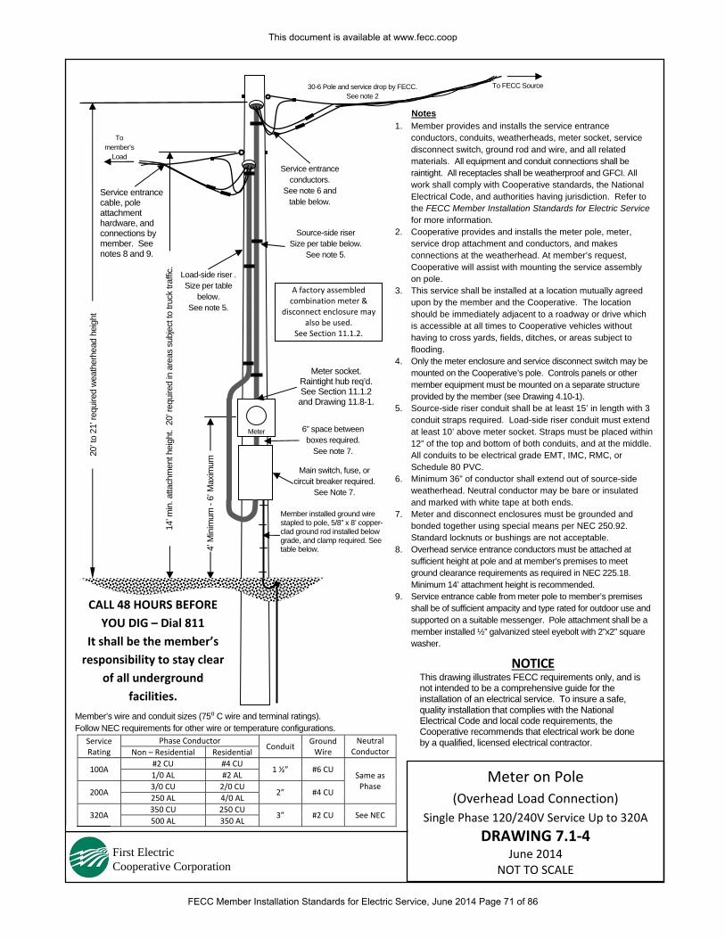
First Electric Cooperative Corporation
1. Member provides and installs the service entrance conductors, conduits, weatherheads, meter socket, service disconnect switch, ground rod and wire, and all related materials. All equipment and conduit connections shall be raintight. All receptacles shall be weatherproof and GFCI. All work shall comply with Cooperative standards, the National Electrical Code, and authorities having jurisdiction. Refer to the FECC Member Installation Standards for Electric Service for more information.
2. Cooperative provides and installs the meter pole, meter, service drop attachment and conductors, and makes connections at the weatherhead. At member’s request, Cooperative will assist with mounting the service assembly on pole.
3. This service shall be installed at a location mutually agreed upon by the member and the Cooperative. The location should be immediately adjacent to a roadway or drive which is accessible at all times to Cooperative vehicles without having to cross yards, fields, ditches, or areas subject to flooding.
4. Only the meter enclosure and service disconnect switch may be mounted on the Cooperative’s pole. Controls panels or other member equipment must be mounted on a separate structure provided by the member (see Drawing 4.10-1).
5. Source-side riser conduit shall be at least 15’ in length with 3 conduit straps required. Load-side riser conduit must extend at least 10’ above meter socket. Straps must be placed within 12” of the top and bottom of both conduits, and at the middle. All conduits to be electrical grade EMT, IMC, RMC, or Schedule 80 PVC.
6. Minimum 36” of conductor shall extend out of source-side weatherhead. Neutral conductor may be bare or insulated and marked with white tape at both ends.
7. Meter and disconnect enclosures must be grounded and bonded together using special means per NEC 250.92. Standard locknuts or bushings are not acceptable.
8. Overhead service entrance conductors must be attached at sufficient height at pole and at member’s premises to meet ground clearance requirements as required in NEC 225.18. Minimum 14’ attachment height is recommended.
9. Service entrance cable from meter pole to member’s premises shall be of sufficient ampacity and type rated for outdoor use and supported on a suitable messenger. Pole attachment shall be a member installed ½” galvanized steel eyebolt with 2”x2” square washer.
Notes
20’ t
o 21
’ req
uire
d w
eath
erhe
ad h
eigh
t
4’ M
inim
um -
6’ M
axim
um
CALL 48 HOURS BEFORE
YOU DIG – Dial 811
It shall be the member’s
responsibility to stay clear
of all underground
facilities.
To FECC Source
Source-side riser Size per table below.
See note 5.
Meter
Member installed ground wire stapled to pole, 5/8” x 8’ copper-clad ground rod installed below grade, and clamp required. See table below.
6” space between boxes required.
See note 7.
30-6 Pole and service drop by FECC. See note 2
Service entrance conductors.
See note 6 and table below.
To member’s
Load
Meter socket. Raintight hub req’d. See Section 11.1.2 and Drawing 11.8-1.
Service entrance cable, pole attachment hardware, and connections by member. See notes 8 and 9.
Main switch, fuse, or circuit breaker required.
See Note 7.
NOTICE This drawing illustrates FECC requirements only, and is not intended to be a comprehensive guide for the installation of an electrical service. To insure a safe, quality installation that complies with the National Electrical Code and local code requirements, the Cooperative recommends that electrical work be done by a qualified, licensed electrical contractor.
14’ m
in. a
ttach
men
t hei
ght.
20’
requ
ired
in a
reas
sub
ject
to tr
uck
traffi
c.
Load-side riser . Size per table
below. See note 5.
Member’s wire and conduit sizes (75⁰ C wire and terminal ratings). Follow NEC requirements for other wire or temperature configurations.
Service Rating
Phase Conductor Conduit
Ground Wire
Neutral Conductor Non – Residential Residential
100A #2 CU #4 CU
1 ½” #6 CU Same as Phase
1/0 AL #2 AL
200A 3/0 CU 2/0 CU
2” #4 CU 250 AL 4/0 AL
320A 350 CU 250 CU
3” #2 CU See NEC 500 AL 350 AL
A factory assembled combination meter &
disconnect enclosure may also be used.
See Section 11.1.2.
Meter on Pole
(Overhead Load Connection)
Single Phase 120/240V Service Up to 320A
DRAWING 7.1‐4 June 2014
NOT TO SCALE
This document is available at www.fecc.coop
FECC Member Installation Standards for Electric Service, June 2014 Page 71 of 86
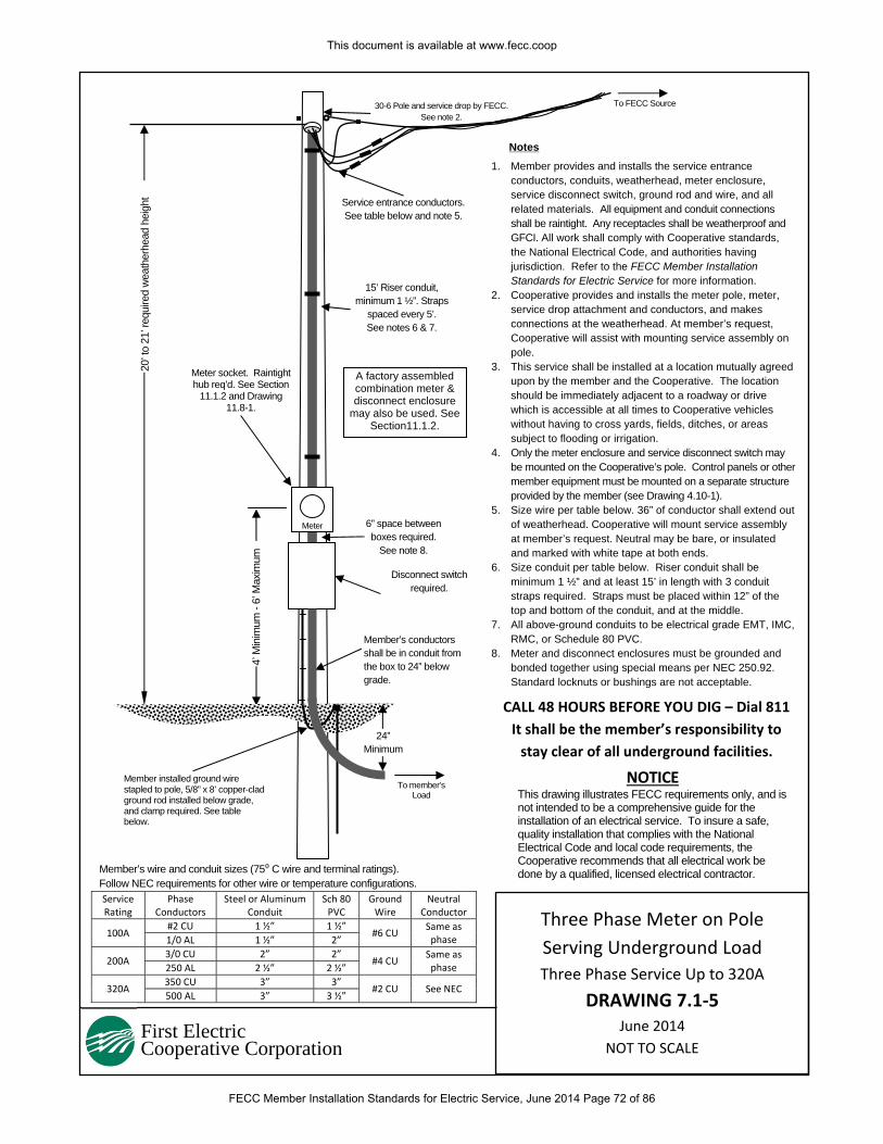
First Electric Cooperative Corporation
1. Member provides and installs the service entrance conductors, conduits, weatherhead, meter enclosure, service disconnect switch, ground rod and wire, and all related materials. All equipment and conduit connections shall be raintight. Any receptacles shall be weatherproof and GFCI. All work shall comply with Cooperative standards, the National Electrical Code, and authorities having jurisdiction. Refer to the FECC Member Installation Standards for Electric Service for more information.
2. Cooperative provides and installs the meter pole, meter, service drop attachment and conductors, and makes connections at the weatherhead. At member’s request, Cooperative will assist with mounting service assembly on pole.
3. This service shall be installed at a location mutually agreed upon by the member and the Cooperative. The location should be immediately adjacent to a roadway or drive which is accessible at all times to Cooperative vehicles without having to cross yards, fields, ditches, or areas subject to flooding or irrigation.
4. Only the meter enclosure and service disconnect switch may be mounted on the Cooperative’s pole. Control panels or other member equipment must be mounted on a separate structure provided by the member (see Drawing 4.10-1).
5. Size wire per table below. 36” of conductor shall extend out of weatherhead. Cooperative will mount service assembly at member’s request. Neutral may be bare, or insulated and marked with white tape at both ends.
6. Size conduit per table below. Riser conduit shall be minimum 1 ½” and at least 15’ in length with 3 conduit straps required. Straps must be placed within 12” of the top and bottom of the conduit, and at the middle.
7. All above-ground conduits to be electrical grade EMT, IMC, RMC, or Schedule 80 PVC.
8. Meter and disconnect enclosures must be grounded and bonded together using special means per NEC 250.92. Standard locknuts or bushings are not acceptable.
Notes20
’ to
21’ r
equi
red
wea
ther
head
hei
ght
4’ M
inim
um -
6’ M
axim
um
CALL 48 HOURS BEFORE YOU DIG – Dial 811
It shall be the member’s responsibility to
stay clear of all underground facilities.
NOTICE This drawing illustrates FECC requirements only, and is not intended to be a comprehensive guide for the installation of an electrical service. To insure a safe, quality installation that complies with the National Electrical Code and local code requirements, the Cooperative recommends that all electrical work be done by a qualified, licensed electrical contractor.
To FECC Source
15’ Riser conduit, minimum 1 ½”. Straps
spaced every 5’. See notes 6 & 7.
Meter
Disconnect switch required.
Member installed ground wire stapled to pole, 5/8” x 8’ copper-clad ground rod installed below grade, and clamp required. See table below.
6” space between boxes required.
See note 8.
30-6 Pole and service drop by FECC. See note 2.
Service entrance conductors. See table below and note 5.
Meter socket. Raintight hub req’d. See Section
11.1.2 and Drawing 11.8-1.
A factory assembled combination meter & disconnect enclosure
may also be used. See Section11.1.2.
Member’s conductors shall be in conduit from the box to 24” below grade.
24” Minimum
To member’s Load
Member’s wire and conduit sizes (75⁰ C wire and terminal ratings). Follow NEC requirements for other wire or temperature configurations. Service Rating
Phase Conductors
Steel or Aluminum Conduit
Sch 80 PVC
Ground Wire
Neutral Conductor
100A #2 CU 1 ½” 1 ½”
#6 CU Same as phase 1/0 AL 1 ½” 2”
200A 3/0 CU 2” 2”
#4 CU Same as phase 250 AL 2 ½” 2 ½”
320A 350 CU 3” 3”
#2 CU See NEC 500 AL 3” 3 ½”
Three Phase Meter on Pole
Serving Underground Load
Three Phase Service Up to 320A
DRAWING 7.1‐5 June 2014
NOT TO SCALE
This document is available at www.fecc.coop
FECC Member Installation Standards for Electric Service, June 2014 Page 72 of 86
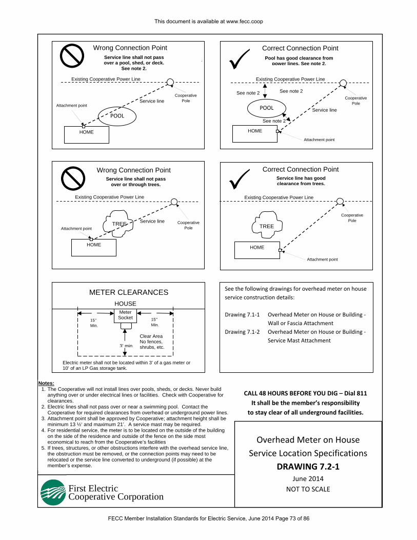
First Electric Cooperative Corporation
Notes: 1. The Cooperative will not install lines over pools, sheds, or decks. Never build
anything over or under electrical lines or facilities. Check with Cooperative for clearances.
2. Electric lines shall not pass over or near a swimming pool. Contact the Cooperative for required clearances from overhead or underground power lines.
3. Attachment point shall be approved by Cooperative; attachment height shall be minimum 13 ½‘ and maximum 21’. A service mast may be required.
4. For residential service, the meter is to be located on the outside of the building on the side of the residence and outside of the fence on the side most economical to reach from the Cooperative’s facilities
5. If trees, structures, or other obstructions interfere with the overhead service line, the obstruction must be removed, or the connection points may need to be relocated or the service line converted to underground (if possible) at the member’s expense.
Wrong Connection Point
METER CLEARANCES
HOME
HOME HOME
Cooperative Pole
Attachment point
HOME
Attachment point
Cooperative Pole
CALL 48 HOURS BEFORE YOU DIG – Dial 811
It shall be the member’s responsibility
to stay clear of all underground facilities.
15’’ Min.
15’’ Min.
3’ min.
HOUSE Meter Socket
Clear Area No fences, shrubs, etc.
See note 2
POOL
Existing Cooperative Power Line
POOL
TREETREE
Service line shall not pass over a pool, shed, or deck.
See note 2.
Attachment point
Existing Cooperative Power Line
See note 2
Correct Connection Point
See note 2
Pool has good clearance from power lines. See note 2.
Existing Cooperative Power Line
Cooperative Pole
Wrong Connection PointService line shall not pass
over or through trees.
Service line
Service line
Service line
Cooperative Pole
Existing Cooperative Power Line
Correct Connection Point Service line has good clearance from trees.
See the following drawings for overhead meter on house
service construction details:
Drawing 7.1‐1 Overhead Meter on House or Building ‐
Wall or Fascia Attachment
Drawing 7.1‐2 Overhead Meter on House or Building ‐
Service Mast Attachment
Attachment point
Electric meter shall not be located within 3’ of a gas meter or 10’ of an LP Gas storage tank.
Overhead Meter on House
Service Location Specifications
DRAWING 7.2‐1 June 2014
NOT TO SCALE
This document is available at www.fecc.coop
FECC Member Installation Standards for Electric Service, June 2014 Page 73 of 86
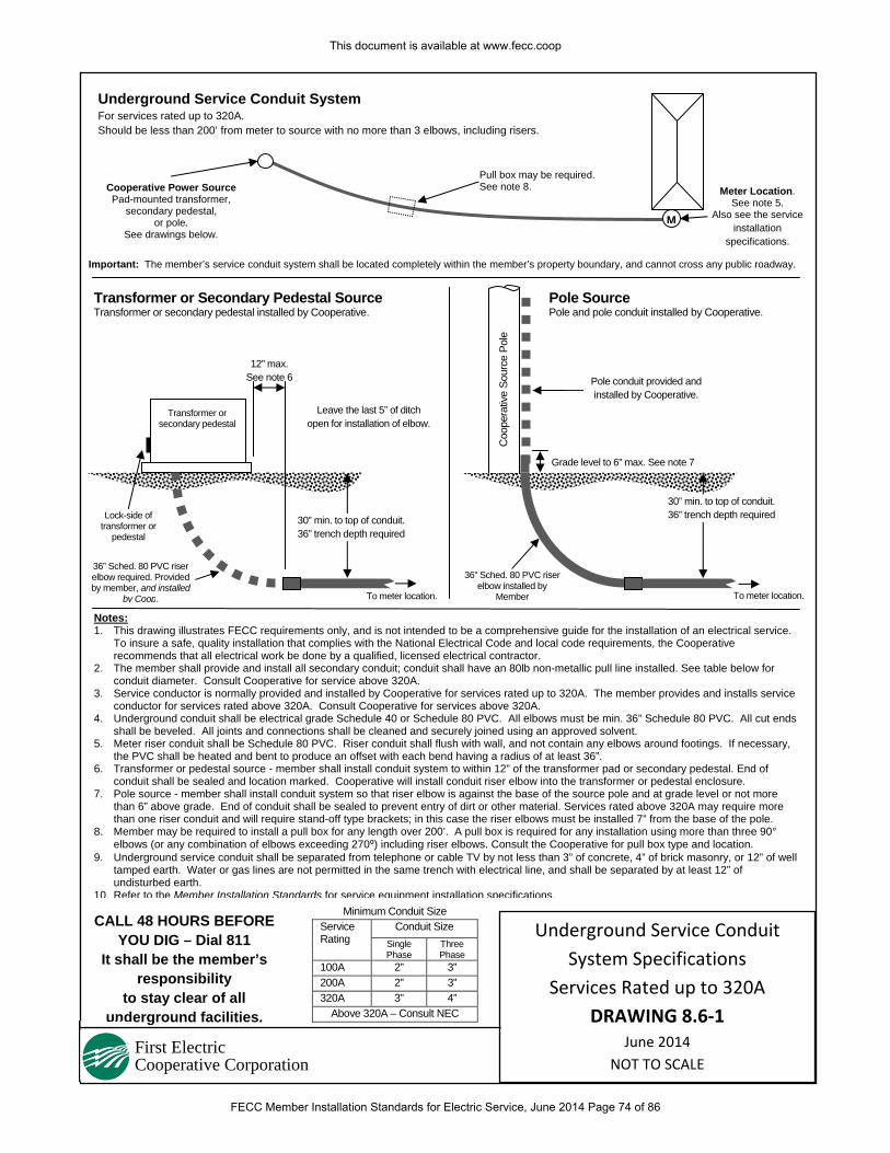
First Electric Cooperative Corporation
Meter Location. See note 5.
Also see the service installation
specifications.
CALL 48 HOURS BEFORE YOU DIG – Dial 811
It shall be the member’s responsibility
to stay clear of all underground facilities.
Cooperative Power Source Pad-mounted transformer,
secondary pedestal, or pole.
See drawings below.
Underground Service Conduit System For services rated up to 320A. Should be less than 200’ from meter to source with no more than 3 elbows, including risers.
Minimum Conduit Size Service Rating
Conduit Size Single Phase
Three Phase
100A 2” 3” 200A 2” 3” 320A 3” 4”
Above 320A – Consult NEC
Notes: 1. This drawing illustrates FECC requirements only, and is not intended to be a comprehensive guide for the installation of an electrical service.
To insure a safe, quality installation that complies with the National Electrical Code and local code requirements, the Cooperative recommends that all electrical work be done by a qualified, licensed electrical contractor.
2. The member shall provide and install all secondary conduit; conduit shall have an 80lb non-metallic pull line installed. See table below for conduit diameter. Consult Cooperative for service above 320A.
3. Service conductor is normally provided and installed by Cooperative for services rated up to 320A. The member provides and installs service conductor for services rated above 320A. Consult Cooperative for services above 320A.
4. Underground conduit shall be electrical grade Schedule 40 or Schedule 80 PVC. All elbows must be min. 36” Schedule 80 PVC. All cut ends shall be beveled. All joints and connections shall be cleaned and securely joined using an approved solvent.
5. Meter riser conduit shall be Schedule 80 PVC. Riser conduit shall flush with wall, and not contain any elbows around footings. If necessary, the PVC shall be heated and bent to produce an offset with each bend having a radius of at least 36”.
6. Transformer or pedestal source - member shall install conduit system to within 12” of the transformer pad or secondary pedestal. End of conduit shall be sealed and location marked. Cooperative will install conduit riser elbow into the transformer or pedestal enclosure.
7. Pole source - member shall install conduit system so that riser elbow is against the base of the source pole and at grade level or not more than 6” above grade. End of conduit shall be sealed to prevent entry of dirt or other material. Services rated above 320A may require more than one riser conduit and will require stand-off type brackets; in this case the riser elbows must be installed 7” from the base of the pole.
8. Member may be required to install a pull box for any length over 200’. A pull box is required for any installation using more than three 90° elbows (or any combination of elbows exceeding 270⁰) including riser elbows. Consult the Cooperative for pull box type and location.
9. Underground service conduit shall be separated from telephone or cable TV by not less than 3” of concrete, 4” of brick masonry, or 12” of well tamped earth. Water or gas lines are not permitted in the same trench with electrical line, and shall be separated by at least 12” of undisturbed earth.
10. Refer to the Member Installation Standards for service equipment installation specifications.
Pull box may be required. See note 8.
M
12” max. See note 6
Lock-side of transformer or
pedestal
36” Sched. 80 PVC riser elbow required. Provided by member, and installed
by Coop.
Transformer or secondary pedestal
Pole Source Pole and pole conduit installed by Cooperative.
Coo
pera
tive
Sour
ce P
ole
36” Sched. 80 PVC riser elbow installed by
Member
Grade level to 6” max. See note 7
To meter location.To meter location.
30” min. to top of conduit. 36” trench depth required
30” min. to top of conduit. 36” trench depth required
Transformer or Secondary Pedestal Source Transformer or secondary pedestal installed by Cooperative.
Pole conduit provided and installed by Cooperative.
Important: The member’s service conduit system shall be located completely within the member’s property boundary, and cannot cross any public roadway.
Leave the last 5” of ditch open for installation of elbow.
Underground Service Conduit
System Specifications
Services Rated up to 320A
DRAWING 8.6‐1 June 2014
NOT TO SCALE
This document is available at www.fecc.coop
FECC Member Installation Standards for Electric Service, June 2014 Page 74 of 86
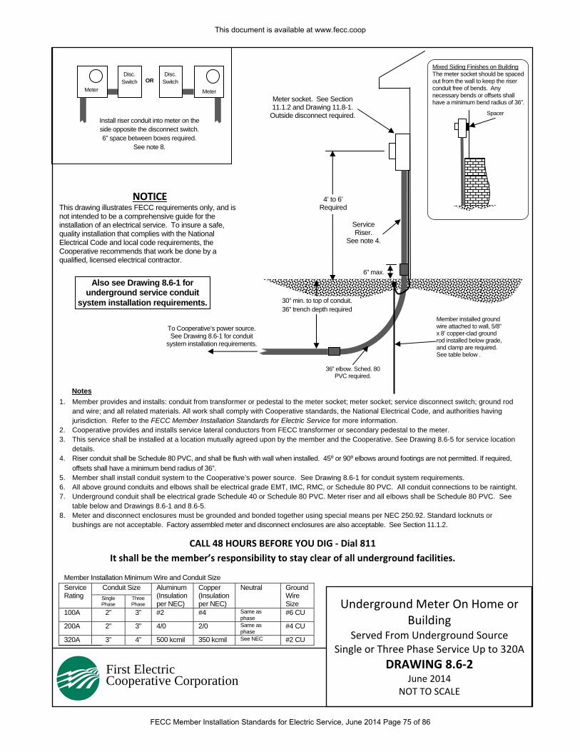
First Electric Cooperative Corporation
CALL 48 HOURS BEFORE YOU DIG ‐ Dial 811
It shall be the member’s responsibility to stay clear of all underground facilities.
NOTICE This drawing illustrates FECC requirements only, and is not intended to be a comprehensive guide for the installation of an electrical service. To insure a safe, quality installation that complies with the National Electrical Code and local code requirements, the Cooperative recommends that work be done by a qualified, licensed electrical contractor.
Notes
To Cooperative’s power source. See Drawing 8.6-1 for conduit
system installation requirements.
36” elbow. Sched. 80 PVC required.
6” max.
1. Member provides and installs: conduit from transformer or pedestal to the meter socket; meter socket; service disconnect switch; ground rod and wire; and all related materials. All work shall comply with Cooperative standards, the National Electrical Code, and authorities having jurisdiction. Refer to the FECC Member Installation Standards for Electric Service for more information.
2. Cooperative provides and installs service lateral conductors from FECC transformer or secondary pedestal to the meter. 3. This service shall be installed at a location mutually agreed upon by the member and the Cooperative. See Drawing 8.6-5 for service location
details. 4. Riser conduit shall be Schedule 80 PVC, and shall be flush with wall when installed. 45⁰ or 90⁰ elbows around footings are not permitted. If required,
offsets shall have a minimum bend radius of 36”. 5. Member shall install conduit system to the Cooperative’s power source. See Drawing 8.6-1 for conduit system requirements. 6. All above ground conduits and elbows shall be electrical grade EMT, IMC, RMC, or Schedule 80 PVC. All conduit connections to be raintight. 7. Underground conduit shall be electrical grade Schedule 40 or Schedule 80 PVC. Meter riser and all elbows shall be Schedule 80 PVC. See
table below and Drawings 8.6-1 and 8.6-5. 8. Meter and disconnect enclosures must be grounded and bonded together using special means per NEC 250.92. Standard locknuts or
bushings are not acceptable. Factory assembled meter and disconnect enclosures are also acceptable. See Section 11.1.2.
Member installed ground wire attached to wall, 5/8” x 8’ copper-clad ground rod installed below grade, and clamp are required. See table below .
Meter socket. See Section 11.1.2 and Drawing 11.8-1.
Outside disconnect required.
Disc. Switch
Disc. Switch OR
Install riser conduit into meter on the side opposite the disconnect switch. 6” space between boxes required.
See note 8.
4’ to 6’ Required
Meter Meter
30” min. to top of conduit. 36” trench depth required
Mixed Siding Finishes on Building The meter socket should be spaced out from the wall to keep the riser conduit free of bends. Any necessary bends or offsets shall have a minimum bend radius of 36”.
Spacer
Service Riser.
See note 4.
Member Installation Minimum Wire and Conduit Size Service Rating
Conduit Size Aluminum (Insulation per NEC)
Copper (Insulation per NEC)
Neutral Ground Wire Size
Single Phase
Three Phase
100A 2” 3” #2 #4 Same as phase
#6 CU
200A 2” 3” 4/0 2/0 Same as phase
#4 CU
320A 3” 4” 500 kcmil 350 kcmil See NEC #2 CU
Also see Drawing 8.6-1 for underground service conduit
system installation requirements.
Underground Meter On Home or Building
Served From Underground Source Single or Three Phase Service Up to 320A
DRAWING 8.6‐2 June 2014
NOT TO SCALE
This document is available at www.fecc.coop
FECC Member Installation Standards for Electric Service, June 2014 Page 75 of 86
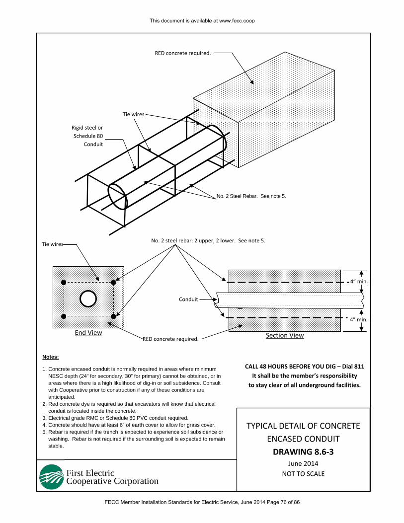
First Electric Cooperative Corporation
No. 2 Steel Rebar. See note 5.
CALL 48 HOURS BEFORE YOU DIG – Dial 811
It shall be the member’s responsibility
to stay clear of all underground facilities.
RED concrete required.
Rigid steel or
Schedule 80
Conduit
Tie wires
RED concrete required.
Tie wires No. 2 steel rebar: 2 upper, 2 lower. See note 5.
Conduit
4” min.
End View Section View
4” min.
Notes: 1. Concrete encased conduit is normally required in areas where minimum
NESC depth (24” for secondary, 30” for primary) cannot be obtained, or in areas where there is a high likelihood of dig-in or soil subsidence. Consult with Cooperative prior to construction if any of these conditions are anticipated.
2. Red concrete dye is required so that excavators will know that electrical conduit is located inside the concrete.
3. Electrical grade RMC or Schedule 80 PVC conduit required. 4. Concrete should have at least 6” of earth cover to allow for grass cover. 5. Rebar is required if the trench is expected to experience soil subsidence or
washing. Rebar is not required if the surrounding soil is expected to remain stable.
TYPICAL DETAIL OF CONCRETE
ENCASED CONDUIT
DRAWING 8.6‐3 June 2014
NOT TO SCALE
This document is available at www.fecc.coop
FECC Member Installation Standards for Electric Service, June 2014 Page 76 of 86
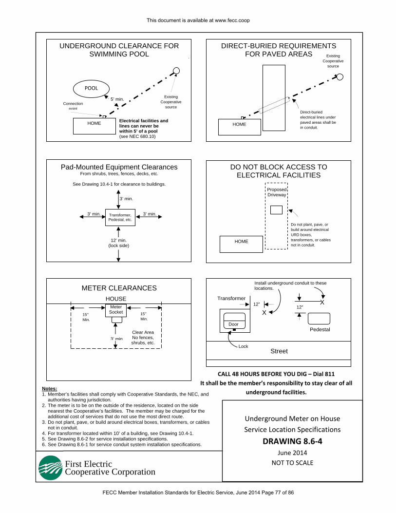
First Electric Cooperative Corporation
Notes: 1. Member’s facilities shall comply with Cooperative Standards, the NEC, and
authorities having jurisdiction. 2. The meter is to be on the outside of the residence, located on the side
nearest the Cooperative’s facilities. The member may be charged for the additional cost of services that do not use the most direct route.
3. Do not plant, pave, or build around electrical boxes, transformers, or cables not in conduit.
4. For transformer located within 10’ of a building, see Drawing 10.4-1. 5. See Drawing 8.6-2 for service installation specifications. 6. See Drawing 8.6-1 for service conduit system installation specifications.
UNDERGROUND CLEARANCE FOR SWIMMING POOL
DIRECT-BURIED REQUIREMENTS FOR PAVED AREAS
Pad-Mounted Equipment Clearances From shrubs, trees, fences, decks, etc.
See Drawing 10.4-1 for clearance to buildings.
DO NOT BLOCK ACCESS TO ELECTRICAL FACILITIES
METER CLEARANCES
HOME
HOME
Existing Cooperative
source Direct-buried electrical lines under paved areas shall be in conduit.
HOME
Connection point
Existing Cooperative
source
CALL 48 HOURS BEFORE YOU DIG – Dial 811
It shall be the member’s responsibility to stay clear of all
underground facilities.
15’’ Min.
15’’ Min.
3’ min.
HOUSE Meter Socket
Clear Area No fences, shrubs, etc.
Proposed Driveway
POOL
Electrical facilities and lines can never be within 5’ of a pool (see NEC 680.10)
Do not plant, pave, or build around electrical URD boxes, transformers, or cables not in conduit.
Transformer, Pedestal, etc.
3’ min.
3’ min. 3’ min.
12’ min. (lock side)
X
Install underground conduit to these locations.
Street
Door
Lock
Pedestal
X
Transformer 12” 12”
5’ min.
Underground Meter on House
Service Location Specifications
DRAWING 8.6‐4 June 2014
NOT TO SCALE
This document is available at www.fecc.coop
FECC Member Installation Standards for Electric Service, June 2014 Page 77 of 86
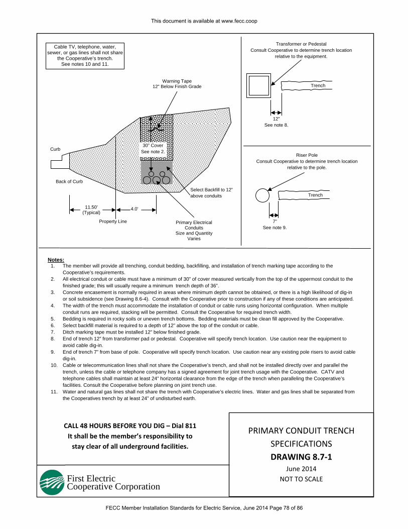
First Electric Cooperative Corporation
CALL 48 HOURS BEFORE YOU DIG – Dial 811
It shall be the member’s responsibility to
stay clear of all underground facilities.
Notes: 1. The member will provide all trenching, conduit bedding, backfilling, and installation of trench marking tape according to the
Cooperative’s requirements. 2. All electrical conduit or cable must have a minimum of 30” of cover measured vertically from the top of the uppermost conduit to the
finished grade; this will usually require a minimum trench depth of 36”. 3. Concrete encasement is normally required in areas where minimum depth cannot be obtained, or there is a high likelihood of dig-in
or soil subsidence (see Drawing 8.6-4). Consult with the Cooperative prior to construction if any of these conditions are anticipated. 4. The width of the trench must accommodate the installation of conduit or cable runs using horizontal configuration. When multiple
conduit runs are required, stacking will be permitted. Consult the Cooperative for required trench width. 5. Bedding is required in rocky soils or uneven trench bottoms. Bedding materials must be clean fill approved by the Cooperative. 6. Select backfill material is required to a depth of 12” above the top of the conduit or cable. 7. Ditch marking tape must be installed 12” below finished grade. 8. End of trench 12” from transformer pad or pedestal. Cooperative will specify trench location. Use caution near the equipment to
avoid cable dig-in. 9. End of trench 7” from base of pole. Cooperative will specify trench location. Use caution near any existing pole risers to avoid cable
dig-in. 10. Cable or telecommunication lines shall not share the Cooperative’s trench, and shall not be installed directly over and parallel the
trench, unless the cable or telephone company has a signed agreement for joint trench usage with the Cooperative. CATV and telephone cables shall maintain at least 24” horizontal clearance from the edge of the trench when paralleling the Cooperative’s facilities. Consult the Cooperative before planning on joint trench use.
11. Water and natural gas lines shall not share the trench with Cooperative’s electric lines. Water and gas lines shall be separated from the Cooperatives trench by at least 24” of undisturbed earth.
Warning Tape 12” Below Finish Grade
Select Backfill to 12” above conduits
Primary Electrical Conduits
Size and Quantity Varies
4.0’ 11.50’ (Typical)
Property Line
Back of Curb
Curb 30” Cover
See note 2.
Cable TV, telephone, water, sewer, or gas lines shall not share
the Cooperative’s trench. See notes 10 and 11.
Trench
Transformer or Pedestal Consult Cooperative to determine trench location
relative to the equipment.
12” See note 8.
Trench
Riser Pole Consult Cooperative to determine trench location
relative to the pole.
7” See note 9.
PRIMARY CONDUIT TRENCH
SPECIFICATIONS
DRAWING 8.7‐1 June 2014
NOT TO SCALE
This document is available at www.fecc.coop
FECC Member Installation Standards for Electric Service, June 2014 Page 78 of 86
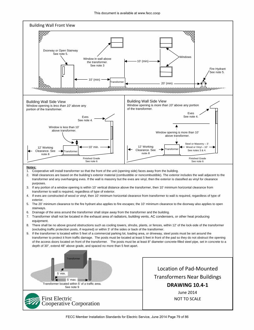
First Electric Cooperative Corporation
Notes: 1. Cooperative will install transformer so that the front of the unit (opening side) faces away from the building. 2. Wall clearances are based on the building’s exterior material (combustible or noncombustible). The exterior includes the wall adjacent to the
transformer and any overhanging eves. If the wall is masonry but the eves are vinyl, then the exterior is classified as vinyl for clearance purposes.
3. If any portion of a window opening is within 10’ vertical distance above the transformer, then 10’ minimum horizontal clearance from transformer to wall is required, regardless of type of exterior.
4. If eves are constructed of wood or vinyl, then 10’ minimum horizontal clearance from transformer to wall is required, regardless of type of exterior.
5. The 20’ minimum clearance to the fire hydrant also applies to fire escapes; the 10’ minimum clearance to the doorway also applies to open stairways.
6. Drainage of the area around the transformer shall slope away from the transformer and the building. 7. Transformer shall not be located in the exhaust area of radiators, building vents, AC condensers, or other heat producing
equipment. 8. There shall be no above ground obstructions such as cooling towers, shrubs, plants, or fences, within 12’ of the lock-side of the transformer
(excluding traffic protection posts, if required) or within 3’ of the sides or back of the transformer. 9. If the transformer is located within 5 feet of a commercial parking lot, loading area, or driveway, steel posts must be set around the
transformer to protect it from traffic damage. The posts must be located at least 5 feet in front of the pad so they do not obstruct the opening of the access doors located on front of the transformer. The posts must be at least 8" diameter concrete-filled steel pipe, set in concrete to a depth of 30", extend 48" above grade, and spaced no more than 5 feet apart.
Building Wall Front View
Building Wall Side View Window opening is less than 10’ above any portion of the transformer.
Transformer
Windows
Fire Hydrant See note 5.
10’ (min)
10’ (min)Window in wall above
the transformer. See note 3
Transformer
10’ min.
Window is less than 10’ above transformer.
Transformer
Steel or Masonry – 3’Wood or Vinyl – 10’
See notes 3 & 4.
Finished Grade See note 6
20’ (min)
Window opening is more than 10’ above transformer.
Doorway or Open Stairway See note 5.
Building Wall Side View Window opening is more than 10’ above any portion of the transformer.
5’ min.
5’ max.Transformer located within 5’ of a traffic area.
See note 9
Transformer
Finished Grade See note 6
Eves See note 4.
Eves See note 4.
12’ Working Clearance. See
note 8
12’ Working Clearance. See
note 8
Location of Pad‐Mounted
Transformers Near Buildings
DRAWING 10.4‐1 June 2014
NOT TO SCALE
This document is available at www.fecc.coop
FECC Member Installation Standards for Electric Service, June 2014 Page 79 of 86
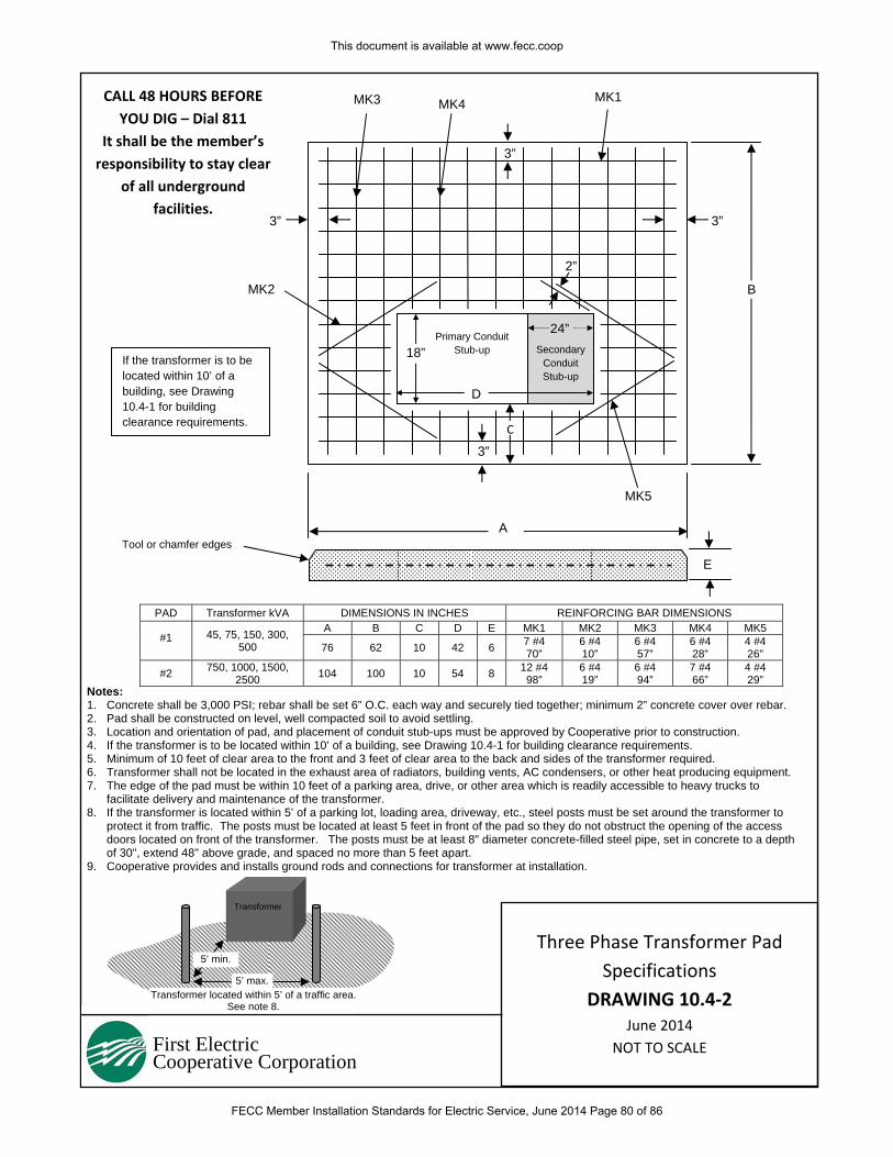
First Electric Cooperative Corporation
PAD Transformer kVA DIMENSIONS IN INCHES REINFORCING BAR DIMENSIONS
#1 45, 75, 150, 300, 500
A B C D E MK1 MK2 MK3 MK4 MK5
76 62 10 42 6 7 #4 70”
6 #4 10”
6 #4 57”
6 #4 28”
4 #4 26”
#2 750, 1000, 1500, 2500 104 100 10 54 8 12 #4
98” 6 #4 19”
6 #4 94”
7 #4 66”
4 #4 29”
MK3 MK4
3”
3” 3”
3”
2”
MK5
MK2
C
B
A
E
Primary Conduit Stub-up
D
18” Secondary Conduit Stub-up
24”
Notes: 1. Concrete shall be 3,000 PSI; rebar shall be set 6” O.C. each way and securely tied together; minimum 2” concrete cover over rebar. 2. Pad shall be constructed on level, well compacted soil to avoid settling. 3. Location and orientation of pad, and placement of conduit stub-ups must be approved by Cooperative prior to construction. 4. If the transformer is to be located within 10’ of a building, see Drawing 10.4-1 for building clearance requirements. 5. Minimum of 10 feet of clear area to the front and 3 feet of clear area to the back and sides of the transformer required. 6. Transformer shall not be located in the exhaust area of radiators, building vents, AC condensers, or other heat producing equipment. 7. The edge of the pad must be within 10 feet of a parking area, drive, or other area which is readily accessible to heavy trucks to
facilitate delivery and maintenance of the transformer. 8. If the transformer is located within 5’ of a parking lot, loading area, driveway, etc., steel posts must be set around the transformer to
protect it from traffic. The posts must be located at least 5 feet in front of the pad so they do not obstruct the opening of the access doors located on front of the transformer. The posts must be at least 8" diameter concrete-filled steel pipe, set in concrete to a depth of 30", extend 48" above grade, and spaced no more than 5 feet apart.
9. Cooperative provides and installs ground rods and connections for transformer at installation.
5’ min.
5’ max.Transformer located within 5’ of a traffic area.
See note 8.
Transformer
CALL 48 HOURS BEFORE
YOU DIG – Dial 811
It shall be the member’s
responsibility to stay clear
of all underground
facilities.
MK1
Tool or chamfer edges
If the transformer is to be located within 10’ of a building, see Drawing 10.4-1 for building clearance requirements.
Three Phase Transformer Pad
Specifications
DRAWING 10.4‐2 June 2014
NOT TO SCALE
This document is available at www.fecc.coop
FECC Member Installation Standards for Electric Service, June 2014 Page 80 of 86
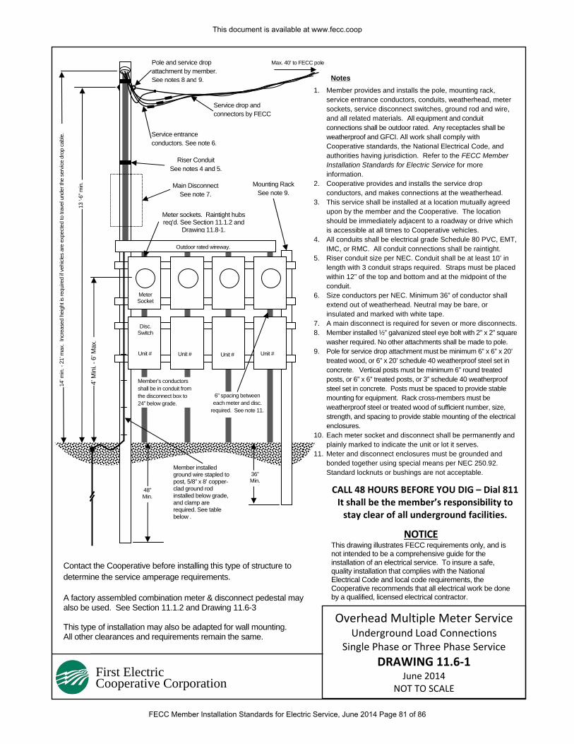
First Electric Cooperative Corporation
1. Member provides and installs the pole, mounting rack, service entrance conductors, conduits, weatherhead, meter sockets, service disconnect switches, ground rod and wire, and all related materials. All equipment and conduit connections shall be outdoor rated. Any receptacles shall be weatherproof and GFCI. All work shall comply with Cooperative standards, the National Electrical Code, and authorities having jurisdiction. Refer to the FECC Member Installation Standards for Electric Service for more information.
2. Cooperative provides and installs the service drop conductors, and makes connections at the weatherhead.
3. This service shall be installed at a location mutually agreed upon by the member and the Cooperative. The location should be immediately adjacent to a roadway or drive which is accessible at all times to Cooperative vehicles.
4. All conduits shall be electrical grade Schedule 80 PVC, EMT, IMC, or RMC. All conduit connections shall be raintight.
5. Riser conduit size per NEC. Conduit shall be at least 10’ in length with 3 conduit straps required. Straps must be placed within 12” of the top and bottom and at the midpoint of the conduit.
6. Size conductors per NEC. Minimum 36” of conductor shall extend out of weatherhead. Neutral may be bare, or insulated and marked with white tape.
7. A main disconnect is required for seven or more disconnects.8. Member installed ½” galvanized steel eye bolt with 2” x 2” square
washer required. No other attachments shall be made to pole. 9. Pole for service drop attachment must be minimum 6” x 6” x 20’
treated wood, or 6” x 20’ schedule 40 weatherproof steel set in concrete. Vertical posts must be minimum 6” round treated posts, or 6” x 6” treated posts, or 3” schedule 40 weatherproof steel set in concrete. Posts must be spaced to provide stable mounting for equipment. Rack cross-members must be weatherproof steel or treated wood of sufficient number, size, strength, and spacing to provide stable mounting of the electrical enclosures.
10. Each meter socket and disconnect shall be permanently and plainly marked to indicate the unit or lot it serves.
11. Meter and disconnect enclosures must be grounded and bonded together using special means per NEC 250.92. Standard locknuts or bushings are not acceptable.
CALL 48 HOURS BEFORE YOU DIG – Dial 811It shall be the member’s responsibility to stay clear of all underground facilities.
4’ M
ini.
- 6’ M
ax.
Meter Socket
Member installed ground wire stapled to post, 5/8” x 8’ copper-clad ground rod installed below grade, and clamp are required. See table below .
36” Min.
48” Min.
14’ m
in. -
21’
max
. In
crea
sed
heig
ht is
requ
ired
if ve
hicle
s ar
e ex
pect
ed to
trav
el u
nder
the
serv
ice d
rop
cabl
e.
Riser Conduit See notes 4 and 5.
Mounting Rack See note 9.
Notes
Service drop and connectors by FECC
Pole and service drop attachment by member. See notes 8 and 9.
Contact the Cooperative before installing this type of structure to determine the service amperage requirements. A factory assembled combination meter & disconnect pedestal may also be used. See Section 11.1.2 and Drawing 11.6-3 This type of installation may also be adapted for wall mounting. All other clearances and requirements remain the same.
13 ‘-
6” m
in.
Max. 40’ to FECC pole
NOTICE This drawing illustrates FECC requirements only, and is not intended to be a comprehensive guide for the installation of an electrical service. To insure a safe, quality installation that complies with the National Electrical Code and local code requirements, the Cooperative recommends that all electrical work be done by a qualified, licensed electrical contractor.
Outdoor rated wireway.
Disc. Switch
Unit # Unit # Unit # Unit #
6” spacing between each meter and disc.
required. See note 11.
Main Disconnect See note 7.
Member’s conductors shall be in conduit from the disconnect box to 24” below grade.
Service entrance conductors. See note 6.
Meter sockets. Raintight hubs req’d. See Section 11.1.2 and
Drawing 11.8-1.
Overhead Multiple Meter Service Underground Load Connections
Single Phase or Three Phase Service
DRAWING 11.6‐1 June 2014
NOT TO SCALE
This document is available at www.fecc.coop
FECC Member Installation Standards for Electric Service, June 2014 Page 81 of 86
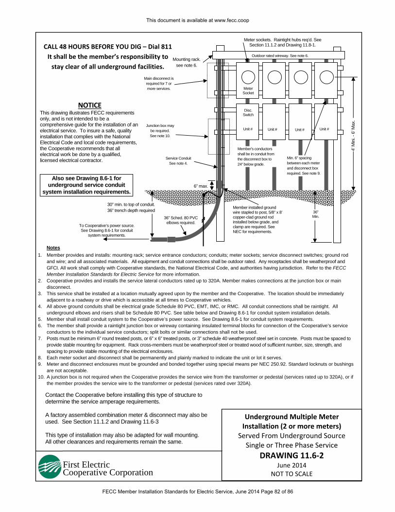
First Electric Cooperative Corporation
1. Member provides and installs: mounting rack; service entrance conductors; conduits; meter sockets; service disconnect switches; ground rod and wire; and all associated materials. All equipment and conduit connections shall be outdoor rated. Any receptacles shall be weatherproof and GFCI. All work shall comply with Cooperative standards, the National Electrical Code, and authorities having jurisdiction. Refer to the FECC Member Installation Standards for Electric Service for more information.
2. Cooperative provides and installs the service lateral conductors rated up to 320A. Member makes connections at the junction box or main disconnect.
3. This service shall be installed at a location mutually agreed upon by the member and the Cooperative. The location should be immediately adjacent to a roadway or drive which is accessible at all times to Cooperative vehicles.
4. All above ground conduits shall be electrical grade Schedule 80 PVC, EMT, IMC, or RMC. All conduit connections shall be raintight. All underground elbows and risers shall be Schedule 80 PVC. See table below and Drawing 8.6-1 for conduit system installation details.
5. Member shall install conduit system to the Cooperative’s power source. See Drawing 8.6-1 for conduit system requirements. 6. The member shall provide a raintight junction box or wireway containing insulated terminal blocks for connection of the Cooperative’s service
conductors to the individual service conductors; split bolts or similar connections shall not be used. 7. Posts must be minimum 6” round treated posts, or 6” x 6” treated posts, or 3” schedule 40 weatherproof steel set in concrete. Posts must be spaced to
provide stable mounting for equipment. Rack cross-members must be weatherproof steel or treated wood of sufficient number, size, strength, and spacing to provide stable mounting of the electrical enclosures.
8. Each meter socket and disconnect shall be permanently and plainly marked to indicate the unit or lot it serves. 9. Meter and disconnect enclosures must be grounded and bonded together using special means per NEC 250.92. Standard locknuts or bushings
are not acceptable. 10. A junction box is not required when the Cooperative provides the service wire from the transformer or pedestal (services rated up to 320A), or if
the member provides the service wire to the transformer or pedestal (services rated over 320A).
CALL 48 HOURS BEFORE YOU DIG – Dial 811
It shall be the member’s responsibility to
stay clear of all underground facilities.
4’ M
ini.
- 6’ M
ax.
Meter Socket
Member installed ground wire stapled to post, 5/8” x 8’ copper-clad ground rod installed below grade, and clamp are required. See NEC for requirements.
36” Min.
Mounting rack. see note 6.
Contact the Cooperative before installing this type of structure to determine the service amperage requirements. A factory assembled combination meter & disconnect may also be used. See Section 11.1.2 and Drawing 11.6-3 This type of installation may also be adapted for wall mounting. All other clearances and requirements remain the same.
NOTICE This drawing illustrates FECC requirements only, and is not intended to be a comprehensive guide for the installation of an electrical service. To insure a safe, quality installation that complies with the National Electrical Code and local code requirements, the Cooperative recommends that all electrical work be done by a qualified, licensed electrical contractor.
Outdoor rated wireway. See note 6.
Disc. Switch
Unit # Unit # Unit # Unit #
Min. 6” spacing between each meter and disconnect box required. See note 9.
Junction box may be required. See note 10.
30” min. to top of conduit. 36” trench depth required
Notes
Member’s conductors shall be in conduit from the disconnect box to 24” below grade.
Main disconnect is required for 7 or more services.
Service Conduit See note 4.
6” max.
36” Sched. 80 PVC elbows required.
Meter sockets. Raintight hubs req’d. See Section 11.1.2 and Drawing 11.8-1.
To Cooperative’s power source. See Drawing 8.6-1 for conduit
system requirements.
Also see Drawing 8.6-1 for underground service conduit
system installation requirements.
Underground Multiple Meter Installation (2 or more meters)
Served From Underground Source Single or Three Phase Service
DRAWING 11.6‐2 June 2014
NOT TO SCALE
This document is available at www.fecc.coop
FECC Member Installation Standards for Electric Service, June 2014 Page 82 of 86
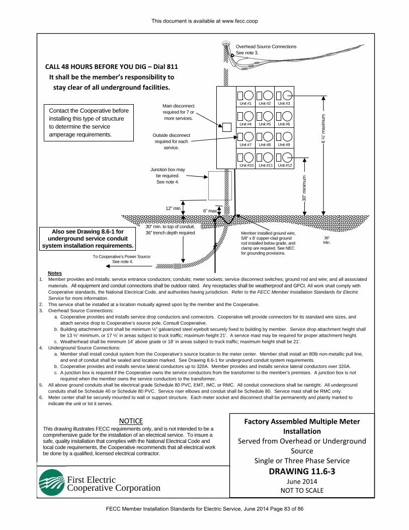
First Electric Cooperative Corporation
1. Member provides and installs: service entrance conductors; conduits; meter sockets; service disconnect switches; ground rod and wire; and all associated materials. All equipment and conduit connections shall be outdoor rated. Any receptacles shall be weatherproof and GFCI. All work shall comply with Cooperative standards, the National Electrical Code, and authorities having jurisdiction. Refer to the FECC Member Installation Standards for Electric Service for more information.
2. This service shall be installed at a location mutually agreed upon by the member and the Cooperative. 3. Overhead Source Connections:
a. Cooperative provides and installs service drop conductors and connectors. Cooperative will provide connectors for its standard wire sizes, and attach service drop to Cooperative’s source pole. Consult Cooperative.
b. Building attachment point shall be minimum ½” galvanized steel eyebolt securely fixed to building by member. Service drop attachment height shall be 13 ½’ minimum, or 17 ½’ in areas subject to truck traffic; maximum height 21’. A service mast may be required for proper attachment height.
c. Weatherhead shall be minimum 14’ above grade or 18’ in areas subject to truck traffic; maximum height shall be 21’. 4. Underground Source Connections:
a. Member shall install conduit system from the Cooperative’s source location to the meter center. Member shall install an 80lb non-metallic pull line, and end of conduit shall be sealed and location marked. See Drawing 8.6-1 for underground conduit system requirements.
b. Cooperative provides and installs service lateral conductors up to 320A. Member provides and installs service lateral conductors over 320A. c. A junction box is required if the Cooperative owns the service conductors from the transformer to the member’s premises. A junction box is not
required when the member owns the service conductors to the transformer. 5. All above ground conduits shall be electrical grade Schedule 80 PVC, EMT, IMC, or RMC. All conduit connections shall be raintight. All underground
conduits shall be Schedule 40 or Schedule 80 PVC. Service riser elbows and conduit shall be Schedule 80. Service mast shall be RMC only. 6. Meter center shall be securely mounted to wall or support structure. Each meter socket and disconnect shall be permanently and plainly marked to
indicate the unit or lot it serves.
CALL 48 HOURS BEFORE YOU DIG – Dial 811
It shall be the member’s responsibility to
stay clear of all underground facilities.
6 ½
’ max
imum
Member installed ground wire, 5/8” x 8’ copper-clad ground rod installed below grade, and clamp are required. See NEC for grounding provisions.
36” Min.
NOTICE This drawing illustrates FECC requirements only, and is not intended to be a comprehensive guide for the installation of an electrical service. To insure a safe, quality installation that complies with the National Electrical Code and local code requirements, the Cooperative recommends that all electrical work be done by a qualified, licensed electrical contractor.
Main disconnect required for 7 or more services.
30” min. to top of conduit. 36” trench depth required
Notes
Junction box may be required. See note 4.
6” max.
30” m
inim
um
Outside disconnect required for each
service.
Unit #1
Unit #4
Unit #7
Unit #10
Unit #2
Unit #5
Unit #8
Unit #11
Unit #3
Unit #6
Unit #9
Unit #12
12” min.
To Cooperative’s Power Source See note 4.
Overhead Source Connections See note 3.
Also see Drawing 8.6-1 for underground service conduit
system installation requirements.
Contact the Cooperative before installing this type of structure to determine the service amperage requirements.
Factory Assembled Multiple Meter Installation
Served from Overhead or Underground Source
Single or Three Phase Service
DRAWING 11.6‐3 June 2014
NOT TO SCALE
This document is available at www.fecc.coop
FECC Member Installation Standards for Electric Service, June 2014 Page 83 of 86
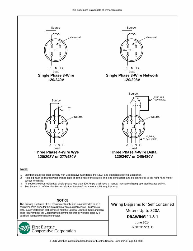
First Electric Cooperative Corporation
Notes: 1. Member’s facilities shall comply with Cooperative Standards, the NEC, and authorities having jurisdiction. 2. High leg must be marked with orange tape at both ends of the source and load conductors and be connected to the right-hand meter
socket terminals. 3. All sockets except residential single-phase less than 320 Amps shall have a manual mechanical gang operated bypass switch. 4. See Section 11 of the Member Installation Standards for meter socket requirements.
Neutral
Source
A B N C Load
Three Phase 4-Wire Delta 120/240V or 240/480V
Neutral
Source
Neutral
Source High Leg See note2.
A B N C Load
Three Phase 4-Wire Wye120/208V or 277/480V
L1 N L2 Load
Single Phase 3-Wire 120/240V
L1 N L2 Load
Single Phase 3-Wire Network120/208V
Neutral
Source
NOTICE This drawing illustrates FECC requirements only, and is not intended to be a comprehensive guide for the installation of an electrical service. To insure a safe, quality installation that complies with the National Electrical Code and local code requirements, the Cooperative recommends that all work be done by a qualified, licensed electrical contractor.
High Leg See note2.
Wiring Diagrams for Self Contained
Meters Up to 320A
DRAWING 11.8‐1 June 2014
NOT TO SCALE
This document is available at www.fecc.coop
FECC Member Installation Standards for Electric Service, June 2014 Page 84 of 86
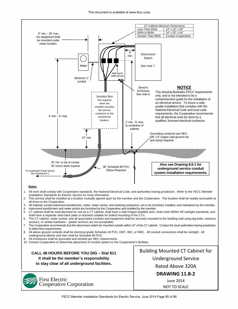
First Electric Cooperative Corporation
CALL 48 HOURS BEFORE YOU DIG – Dial 811 It shall be the member’s responsibility
to stay clear of all underground facilities.
Junction Box Not required
when the member provides
the service conductor to the
transformer location.
Disconnect Switch
See note 7.
1. All work shall comply with Cooperative standards, the National Electrical Code, and authorities having jurisdiction. Refer to the FECC Member
Installation Standards for Electric Service for more information. 2. This service shall be installed at a location mutually agreed upon by the member and the Cooperative. The location shall be readily accessible at
all times to the Cooperative. 3. All material, except instrument transformers, meter, meter socket, and metering conductors, are to be furnished, installed, and maintained by the member.4. Instrument transformers and meter socket are furnished by the Cooperative and installed by the member. 5. CT cabinet shall be manufactured for use as a CT cabinet; shall have a side-hinged sealable door; shall meet NEMA 3R raintight standards, and
shall have a separate steel back plate or brackets suitable for bolted mounting of the CT’s. 6. The CT cabinet, meter socket, and all associated conduits and equipment shall be securely mounted to the building wall using lag bolts, masonry
anchors, or similar hardware – plastic anchors are not acceptable. 7. The Cooperative recommends that the disconnect switch be mounted outside within 24” of the CT cabinet. Contact the local authorities having jurisdiction
to determine requirements. 8. All above ground conduits shall be electrical grade Schedule 40 PVC, EMT, IMC, or RMC. All conduit connections shall be raintight. All
underground elbows and riser shall be Schedule 80 PVC. 9. All enclosures shall be grounded and bonded per NEC requirements. 10. Contact Cooperative to determine placement of conduit system to the Cooperative’s facilities.
2’ min - 6’ max to centerline of
cabinet
4’ min – 6’ max.
6” min – 25’ max No equipment shall be mounted under
meter location.
Minimum 1” conduit
36” Schedule 80 PVC Elbow Required
30” min. to top of conduit. 36” trench depth required
CT Cabinet Minimum Dimensions Less Than 600A 14” x 32” x 40” 600A to 800A 14” x 32” x 54” Greater Than 800A Contact Cooperative
12” min. Grounding conductor per NEC. 5/8” x 8’ copper clad ground rod and clamp required.
NOTICE This drawing illustrates FECC requirements only, and is not intended to be a comprehensive guide for the installation of an electrical service. To insure a safe, quality installation that complies with the National Electrical Code and local code requirements, the Cooperative recommends that all electrical work be done by a qualified, licensed electrical contractor.
High leg for Delta Service
Bond to Enclosure
See note 9.
Notes:
Meter
6” min.
To Cooperative Power Source. See Drawing 8.6-1.
Also see Drawing 8.6-1 for underground service conduit
system installation requirements.
Building Mounted CT Cabinet for
Underground Service
Rated Above 320A
DRAWING 11.8‐2 June 2014
NOT TO SCALE
This document is available at www.fecc.coop
FECC Member Installation Standards for Electric Service, June 2014 Page 85 of 86
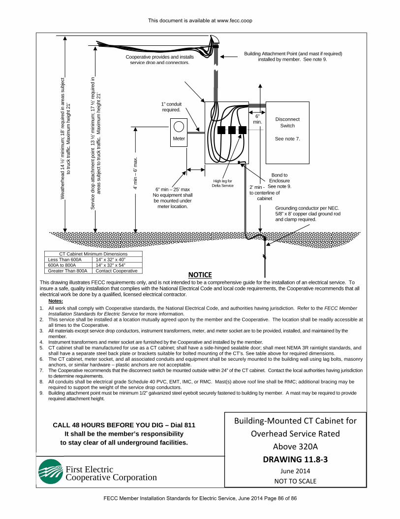
First Electric Cooperative Corporation
CALL 48 HOURS BEFORE YOU DIG – Dial 811 It shall be the member’s responsibility
to stay clear of all underground facilities.
Disconnect Switch
See note 7.
1. All work shall comply with Cooperative standards, the National Electrical Code, and authorities having jurisdiction. Refer to the FECC Member
Installation Standards for Electric Service for more information. 2. This service shall be installed at a location mutually agreed upon by the member and the Cooperative. The location shall be readily accessible at
all times to the Cooperative. 3. All materials except service drop conductors, instrument transformers, meter, and meter socket are to be provided, installed, and maintained by the
member. 4. Instrument transformers and meter socket are furnished by the Cooperative and installed by the member. 5. CT cabinet shall be manufactured for use as a CT cabinet; shall have a side-hinged sealable door; shall meet NEMA 3R raintight standards, and
shall have a separate steel back plate or brackets suitable for bolted mounting of the CT’s. See table above for required dimensions. 6. The CT cabinet, meter socket, and all associated conduits and equipment shall be securely mounted to the building wall using lag bolts, masonry
anchors, or similar hardware – plastic anchors are not acceptable. 7. The Cooperative recommends that the disconnect switch be mounted outside within 24” of the CT cabinet. Contact the local authorities having jurisdiction
to determine requirements. 8. All conduits shall be electrical grade Schedule 40 PVC, EMT, IMC, or RMC. Mast(s) above roof line shall be RMC; additional bracing may be
required to support the weight of the service drop conductors. 9. Building attachment point must be minimum 1/2” galvanized steel eyebolt securely fastened to building by member. A mast may be required to provide
required attachment height.
2’ min - 6’ max to centerline of
cabinet
4’ m
in –
6’ m
ax.
6” min – 25’ max No equipment shall be mounted under
meter location.
1” conduit required.
CT Cabinet Minimum Dimensions Less Than 600A 14” x 32” x 40” 600A to 800A 14” x 32” x 54” Greater Than 800A Contact Cooperative
Grounding conductor per NEC. 5/8” x 8’ copper clad ground rod and clamp required.
NOTICE This drawing illustrates FECC requirements only, and is not intended to be a comprehensive guide for the installation of an electrical service. To insure a safe, quality installation that complies with the National Electrical Code and local code requirements, the Cooperative recommends that all electrical work be done by a qualified, licensed electrical contractor.
High leg for Delta Service
Bond to Enclosure
See note 9.
Notes:
Meter
6” min.
Building Attachment Point (and mast if required) installed by member. See note 9.
Serv
ice d
rop
atta
chm
ent p
oint
13
½’ m
inim
um; 1
7 ½
’ req
uire
d in
ar
eas
subj
ect t
o tru
ck tr
affic
. M
axim
um h
eigh
t 21’
Cooperative provides and installs service drop and connectors.
Wea
ther
head
14
½’ m
inim
um; 1
8’ re
quire
d in
are
as s
ubje
ct
to tr
uck
traffi
c. M
axim
um h
eigh
t 21’
Building‐Mounted CT Cabinet for
Overhead Service Rated
Above 320A
DRAWING 11.8‐3 June 2014
NOT TO SCALE
This document is available at www.fecc.coop
FECC Member Installation Standards for Electric Service, June 2014 Page 86 of 86