Embed Size (px)
Citation preview
Description
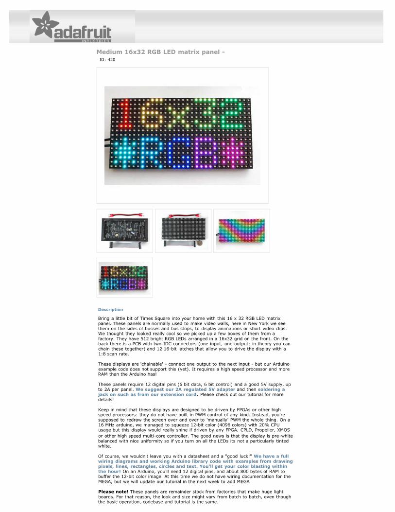
Medium 16x32 RGB LED matrix panel - ID: 420
Bring a little bit of Times Square into your home with this 16 x 32 RGB LED matrixpanel. These panels are normally used to make video walls, here in New York we seethem on the sides of busses and bus stops, to display animations or short video clips.We thought they looked really cool so we picked up a few boxes of them from afactory. They have 512 bright RGB LEDs arranged in a 16x32 grid on the front. On theback there is a PCB with two IDC connectors (one input, one output: in theory you canchain these together) and 12 16-bit latches that allow you to drive the display with a1:8 scan rate.
These displays are 'chainable' - connect one output to the next input - but our Arduinoexample code does not support this (yet). It requires a high speed processor and moreRAM than the Arduino has!
These panels require 12 digital pins (6 bit data, 6 bit control) and a good 5V supply, upto 2A per panel. We suggest our 2A regulated 5V adapter and then soldering ajack on such as from our extension cord. Please check out our tutorial for moredetails!
Keep in mind that these displays are designed to be driven by FPGAs or other highspeed processors: they do not have built in PWM control of any kind. Instead, you'resupposed to redraw the screen over and over to 'manually' PWM the whole thing. On a16 MHz arduino, we managed to squeeze 12-bit color (4096 colors) with 20% CPUusage but this display would really shine if driven by any FPGA, CPLD, Propeller, XMOSor other high speed multi-core controller. The good news is that the display is pre-whitebalanced with nice uniformity so if you turn on all the LEDs its not a particularly tintedwhite.
Of course, we wouldn't leave you with a datasheet and a "good luck!" We have a fullwiring diagrams and working Arduino library code with examples from drawingpixels, lines, rectangles, circles and text. You'll get your color blasting withinthe hour! On an Arduino, you'll need 12 digital pins, and about 800 bytes of RAM tobuffer the 12-bit color image. At this time we do not have wiring documentation for theMEGA, but we will update our tutorial in the next week to add MEGA
Please note! These panels are remainder stock from factories that make huge lightboards. For that reason, the look and size might vary from batch to batch, even thoughthe basic operation, codebase and tutorial is the same.
We don't have a spec or datasheet at this time. However, these are the specificationsfrom the factory
Dimensions: 192mm x 96mm x 12mm (7.6" x 3.8" x 0.5")Panel weight with IDC cable and power cable: 170 g5V regulated power input, 2.5A max (all LEDs on)3-5V data logic level input2000 mcd LEDs on 6mm pitch1/8 scan rateIndoor display, 150 degree visibilityDisplays are 'chainable' - connect one output to the next input - but our Arduinoexample code does not support this yet
Technical Details