Embed Size (px)
Citation preview

Mechanisms and Movement
Mechanisms are used to convert between one type of motion and another. Any machine can be looked on as a group of interconnected mechanisms which convert
one type of motion to a variety of other motions.
These changes may be to convert rotary motion to straight line motion or to convert reciprocal (back and forth) motion to intermittent motion. They may also
transform a fixed type of motion, for example by magnifying a linear motion or by slowing down a
rotary motion.

Mechanisms and MovementIn these lecture slides, motion will be divided into six basic types,
- Linear- Reciprocating- Rotary - Oscillation- Intermittent- Irregular
… And 3 main transformations:- Increase/Decrease- Reflect- Rotate

Motionthe action or process of moving or of changing
place or position; movement.

Mechanical Device
an object that does work

Compound Mechanisman assembly of mechanical devices performing a complete functional motion, often being part of a large
machine; linkage.

Linear MotionLinear motion is the most basic of all motions. Uninterrupted objects will continue to move in a straight line indefinitely. Under every day circumstances gravity and friction conspire to bring objects to rest.
Linear motion is measured in two parts. Speed, and direction. Together these make up the velocity.
Linear motion, is not often used as a starting point for mechanisms. Click on the links below to find how to convert linear motion to other motion types.
Motion

“Rack and Pinion”
The rack and pinion is used to convert between rotary and linear motion. The rack is the flat, toothed part, the pinion is the gear. Rack and pinion can convert from rotary to linear of from linear to rotary.The diameter of the gear determines the speed that the rack moves as the pinion turns. Rack and pinions are commonly used in the steering system of cars to convert the rotary motion of the steering wheel to the side to side motion in the wheels.
Rack and pinion gears give a positive motion especially compared to the friction drive of a wheel in tarmac. In the rack and pinion railway a central rack between the two rails engages with a pinion on the engine allowing the train to be pulled up very steep slopes.
Linear Motion to Rotary Motion

Reflect Linear Motion
On the left is a simple pulley. As the rope is pulled down the weight moves up by the same distance.
In the compound pulley on the right the rope is wrapped around two pulleys. As the rope is pulled the weight, this time attached to the lower pulley rather than direct to the rope, moves up slower than the speed that the rope is pulled. Corresponding to this reduction in speed is an increase in the force on the weight.
The amount of increase in the force depends on how many times the rope wraps round the pulleys. By wrapping the rope several times around the pulleys it is easily possible to lift your own weight off the ground!
“Pulleys”

Reflect Linear Motion
Belt drives are used transfer rotational motion from one place to another.
On the left, both pulleys are the same size. Drive can be transferred by friction of the belt on the pulley or, if required, buy using a toothed belt. Chain drives work in a similar way.
By crossing the belt the direction of drive can be changed. On the right two sizes of pulley are used to show how speed of rotation can be changed.
“Belt Drives”

Levers are an essential part of many mechanisms. They can be used to change the amount, the strength and the direction of movement. The position of the force and the load are interchangeable and by moving them to different points on the lever, different effects can be produced. The fixed point of the lever about which it moves is known as the fulcrum.
In this example the force and the load move in opposite directions. With the force three times closer to the fulcrum them the load lifted is only one third of the force but it move three times as far.
“Levers”Reflect Linear Motion

First order lever. Like a see-saw or balance, the load and the force are separated by the fulcrum. As one moves up the other moves down. The amount and the strength of the movement is proportional to the distance from the fulcrum.
“Levers”Reflect Linear Motion

Second order lever. A wheel barrow is a second order lever. Here the load is between the force and the fulcrum. This uses mechanical advantage to ease lifting of a large weight.
“Levers”Reflect Linear Motion

Third order lever.Here the force is between the fulcrum and the load. Mechanical advantage is reduced but the movement at the load point is increased.
“Levers”Reflect Linear Motion

Reciprocating Motion
Reciprocating motion is back and forth motion. In the example to the left the reciprocating motion of the piston is converted to the rotary motion in the crank.
Reciprocating motion is measured by its throw (the distance between the two extremes of motion) and by its period (the length of time for each cycle)
Motion

Reciprocating to Rotary Motion
This mechanism is used to convert between rotary motion and reciprocating motion, it works either way. Notice how the speed of the piston changes. The piston starts from one end, and increases its speed. It reaches maximum speed in the middle of its travel then gradually slows down until it reaches the end of its travel.
“Piston”
Reciprocating to Oscillating Motion
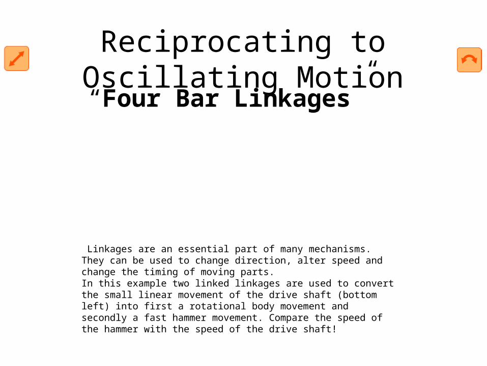
Linkages are an essential part of many mechanisms. They can be used to change direction, alter speed and change the timing of moving parts.In this example two linked linkages are used to convert the small linear movement of the drive shaft (bottom left) into first a rotational body movement and secondly a fast hammer movement. Compare the speed of the hammer with the speed of the drive shaft!
“Four Bar Linkages”
Reciprocating to Oscillating Motion
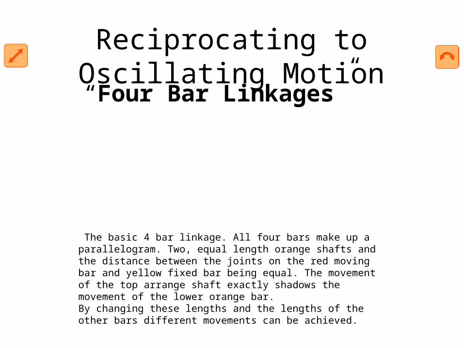
The basic 4 bar linkage. All four bars make up a parallelogram. Two, equal length orange shafts and the distance between the joints on the red moving bar and yellow fixed bar being equal. The movement of the top arrange shaft exactly shadows the movement of the lower orange bar.By changing these lengths and the lengths of the other bars different movements can be achieved.
“Four Bar Linkages”

Reciprocating to Oscillating Motion
This time, two different lengths of bar, the two long bars, yellow and red are the same length as before.Look at the tip of the red shaft, notice how it moves smothly until the last second then flips to the right. The same effect is used in the Motley Man to make him look up at the last moment of his bow.
“Four Bar Linkages”

Reciprocating to Oscillating Motion
Quite an extreme arrangement this! With the two long bars crossing over each other. A more extreme 'kick' in the orange bar this time at the end of the green bar's travel. Looks like a likely mechanism for a model!
“Four Bar Linkages”

The ratchet can be used to move a toothed wheel one tooth at a time. The part used to move the ratchet is known as the pawl.The ratchet can be used as a way of gearing down motion. By its nature motion created by a ratchet is intermittent. By using two pawls simultaniously this intermittent effect can be almost, but not quite, removed.Ratchets are also used to ensure that motion only occurs in only one direction, useful for winding gear which must not be allowed to drop. Ratchets are also used in the freewheel mechanism of a bicycle.
“Ratchet”Reciprocating to Intermittent Motion

Levers are an essential part of many mechanisms. They can be used to change the amount, the strength and the direction of movement. The position of the force and the load are interchangeable and by moving them to different points on the lever, different effects can be produced. The fixed point of the lever about which it moves is known as the fulcrum. In this example the force and the load move in opposite directions. With the force three times closer to the fulcrum them the load lifted is only one third of the force but it move three times as far.
“Lever”
Increase/Decrease Reciprocating Motion

On the left is a simple pulley. As the rope is pulled down the weight moves up by the same distance.
In the compound pulley on the right the rope is wrapped around two pulleys. As the rope is pulled the weight, this time attached to the lower pulley rather than direct to the rope, moves up slower than the speed that the rope is pulled. Corresponding to this reduction in speed is an increase in the force on the weight.
The amount of increase in the force depends on how many times the rope wraps round the pulleys. By wrapping the rope several times around the pulleys it is easily possible to lift your own weight off the ground!
“Pulleys”
Reflect Reciprocating Motion

Reciprocating motion is back and forth motion. In the example to the left the reciprocating motion of the piston is converted to the rotary motion in the crank.
Reciprocating motion is measured by its throw (the distance between the two extremes of motion) and by its period (the length of time for each cycle)
“Bell Crank”Rotate Reciprocating Motion

Rotary MotionRotary motion is motion in a circle. The starting point for many mechanisms. Measurement:Rotary motion is measured in either angular velocity, the number of degrees turned in a given time, or in revolutions per minute (rpm).
The direction of turn, either clockwise or anti-clockwise is also part of the measurement of rotary motion.
The strength of rotary motion is known as the torque, the turning force. Torque is measured in Newton Metres defined as the force of one newton acting at a perpendicular distance of one metre from the axis of rotation.
Motion

Rotary to Linear Motion
The wheel is used to convert rotary motion to linear motion. A central plank of civilisation, there is little point in reinventing it.
“The Wheel”

Rotary to Linear Motion
The rack and pinion is used to convert between rotary and linear motion. The rack is the flat, toothed part, the pinion is the gear. Rack and pinion can convert from rotary to linear of from linear to rotary.
The diameter of the gear determines the speed that the rack moves as the pinion turns. Rack and pinions are commonly used in the steering system of cars to convert the rotary motion of the steering wheel to the side to side motion in the wheels.
Rack and pinion gears give a positive motion especially compared to the friction drive of a wheel in tarmac. In the rack and pinion railway a central rack between the two rails engages with a pinion on the engine allowing the train to be pulled up very steep slopes.
“Rack and Pinion”

Rotary to Reciprocating Motion
This mechanism is used to convert between rotary motion and reciprocating motion, it works either way. Notice how the speed of the piston changes. The piston starts from one end, and increases its speed. It reaches maximum speed in the middle of its travel then gradually slows down until it reaches the end of its travel.
“Piston”

Rotary to Reciprocating Motion
This mechanism is used to convert between rotary motion and reciprocating motion. In this mechanism the straight line motion stays at a constant speed throughout the full length of the throw.
“NO nAME????”

Rotary to Reciprocating Motion
Invented by Girolamo Cardano in the 16th century the Cardan gear is a way of converting rotary motion into straight line motion. Watch how the red dot on the inner purple gear exactly follows the vertical dotted line. The outer gear has a diameter exactly twice as large as the inner gear. In the above example they have 40 and 20 teeth respectively.Cardano also invented a type of universal joint and investigated the mathematics of probability. Understanding the mathematics of risk helped him make a living from gambling until eventually he could find no-one to gamble with and had to move onto new pastures...
“Cardan Gear(straight line motion)”

Rotary to Oscilation
The crank is used to convert rotary motion to reciprocating or oscillating motion. With careful timing it can also be used to convert motion the other way... from reciprocating to rotary, (see the piston)
The throw of the reciprocating motion is determined by the offest of the crank.
“Crank”

Rotary to Oscilation
Oscillating motion is motion which moves along a path, then returns along that same path backwards and forwards, backwards and forwards.
In this example the drive wheel is used to power a waving machine, notice how the left to right movement is slower than the right to left. This is because that left to right motion takes place over a longer part of the drive wheels turn.
By moving the drive wheel closer to the pivot point this effect can be exaggerated. The same mechanism is used in mechanical saws to provide a quick return after the cutting stroke.
“Quick return”

Rotary to Intermittent Motion
The Geneva stop is named after the Geneva cross, a similar shape to the main part of the mechanism.
The Geneva stop is used to provide intermittent motion, the orange wheel turns continuously, the dark blue pin then turns the blue cross quarter of a turn for each revolution of the drive wheel. The crescent shaped cut out in dark orange section lets the points of the cross past, then locks the wheel in place when it is stationary.
The Geneva stop mechanism is used commonly in film projectors to move the film on one frame at a time.
“Geneva Stop”

Rotary to Irregular Motion
Cams are used to convert rotary motion into reciprocating motion. The motion created can be simple and regular or complex and irregular.
As the cam turns, driven by the circular motion, the cam follower traces the surface of the cam transmitting its motion to the required mechanism.
“Cams”

Rotary to Irregular Motion
Cam follower design is important in the way the profile of
the cam is followed. A fine pointed follower will more accurately trace the outline of the cam. This more accurate movement is at the expense of the strength of the cam follower.
“Cams”

Rotary to Irregular Motion
As the cam turns it has a tendency to push the cam follower to one side. To overcome this a separate cam follower and push rod can be used as in this mechanism. Here the cam follower drags over the cam surface, accurately tracing the surface of the cam. Any movement of the cam follower is transferred directly to the push rod
“Cams”

Increase/Decrease Rotary Motion
Gears are used to change speed in rotational movement. In the example above the blue gear has eleven teeth and the orange gear has twenty five. To turn the orange gear one full turn the blue gear must turn 25/11 or 2.2727r turns.Notice that as the blue gear turns clockwise the orange gear turns anti-clockwise.In the above example the number of teeth on the orange gear is not divisible by the number of teeth on the blue gear. This is deliberate. If the orange gear had thirty three teeth then every three turns of the blue gear the same teeth would mesh together which could cause excessive wear. By using none divisible numbers the same teeth mesh only every seventeen turns of the blue gear.
“Gears”

Increase/Decrease Rotary Motion
Chains are used to connect gears. They work in a similar way to pulleys but with a positive drive rather than a reliance on friction. Gears which are connected by chain turn in the same direction unlike gears which mesh against each other.
“Chain and Gear”

Increase/Decrease Rotary Motion
A worm is used to reduce speed. For each complete turn of the worm shaft the gear shaft advances only one tooth of the gear.
In this case, with a twelve tooth gear, the speed is reduced by a factor of twelve. Also, the axis of rotation is turned by 90 degrees.
Unlike ordinary gears, the motion is not reversible, a worm can drive a gear to reduce speed but a gear cannot drive a worm to increase it.
As the speed is reduced the power to the drive increases correspondingly. Worm gears are a compact, efficient means of substantially decreasing speed and increasing power. Ideal for use with small electric motors.
“Worm Gear”

Gears are used to change speed in rotational movement. In the example above the blue gear has eleven teeth and the orange gear has twenty five. To turn the orange gear one full turn the blue gear must turn 25/11 or 2.2727r turns.Notice that as the blue gear turns clockwise the orange gear turns anti-clockwise.
In the above example the number of teeth on the orange gear is not divisible by the number of teeth on the blue gear. This is deliberate. If the orange gear had thirty three teeth then every three turns of the blue gear the same teeth would mesh together which could cause excessive wear. By using none divisible numbers the same teeth mesh only every seventeen turns of the blue gear.
“Gears”Reflect Rotary Motion

The bevel gear is used to change the axis of rotational motion. By using gears of differing numbers of teeth the speed of rotation can also be changed.
“Bevel Gear”Rotate Rotary Motion

OscillationOscillation is back and forth motion about a pivot point. It is measured in terms of both the angle of throw (amplitude) and the period of time for one complete cycle (periodic time) or the number of cycles in a given time (frequency).
Oscillation tends to be an ending point for a mechanism rather than the starting point, however some mechanisms are available to convert or transform oscillations.
Motion

Oscillation to Reciprocating Motion
The crank is used to convert rotary motion to reciprocating or oscillating motion. With careful timing it can also be used to convert motion the other way... from reciprocating to rotary, (see the piston)
The throw of the reciprocating motion is determined by the offest of the crank.
“Crank”

Cams are used to convert rotary motion into reciprocating motion. The motion created can be simple and regular or complex and irregular.
As the cam turns, driven by the circular motion, the cam follower traces the surface of the cam transmitting its motion to the required mechanism.
Oscillation to Reciprocating Motion“Cams”

Cam follower design is important in the way the profile of
the cam is followed. A fine pointed follower will more accurately trace the outline of the cam. This more accurate movement is at the expense of the strength of the cam follower.
Oscillation to Reciprocating Motion“Cams”

As the cam turns it has a tendency to push the cam follower to one side. To overcome this a separate cam follower and push rod can be used as in this mechanism. Here the cam follower drags over the cam surface, accurately tracing the surface of the cam. Any movement of the cam follower is transferred directly to the push rod
Oscillation to Reciprocating Motion“Cams”

The crank is used to convert rotary motion to reciprocating or oscillating motion. With careful timing it can also be used to convert motion the other way... from reciprocating to rotary, (see the piston)The throw of the reciprocating motion is determined by the offest of the crank.
Oscillation to Rotary Motion“Crank”

The ratchet can be used to move a toothed wheel one tooth at a time. The part used to move the ratchet is known as the pawl.
The ratchet can be used as a way of gearing down motion. By its nature motion created by a ratchet is intermittent. By using two pawls simultaniously this intermittent effect can be almost, but not quite, removed.
Ratchets are also used to ensure that motion only occurs in only one direction, useful for winding gear which must not be allowed to drop. Ratchets are also used in the freewheel mechanism of a bicycle.
Oscillation to Intermittent Motion“Ratchet”

Cams are used to convert rotary motion into reciprocating motion. The motion created can be simple and regular or complex and irregular.
As the cam turns, driven by the circular motion, the cam follower traces the surface of the cam transmitting its motion to the required mechanism.
Oscillation to Irregular Motion“Cam”

Cam follower design is important in the way the profile of
the cam is followed. A fine pointed follower will more accurately trace the outline of the cam. This more accurate movement is at the expense of the strength of the cam follower.
Oscillation to Irregular Motion“Cam”

As the cam turns it has a tendency to push the cam follower to one side. To overcome this a separate cam follower and push rod can be used as in this mechanism. Here the cam follower drags over the cam surface, accurately tracing the surface of the cam. Any movement of the cam follower is transferred directly to the push rod
Oscillation to Irregular Motion“Cam”

Gears are used to change speed in rotational movement. In the example above the blue gear has eleven teeth and the orange gear has twenty five. To turn the orange gear one full turn the blue gear must turn 25/11 or 2.2727r turns.Notice that as the blue gear turns clockwise the orange gear turns anti-clockwise.In the above example the number of teeth on the orange gear is not divisible by the number of teeth on the blue gear. This is deliberate. If the orange gear had thirty three teeth then every three turns of the blue gear the same teeth would mesh together which could cause excessive wear. By using none divisible numbers the same teeth mesh only every seventeen turns of the blue gear.
Increase/Decrease Oscillation“Gears”

Gears are used to change speed in rotational movement. In the example above the blue gear has eleven teeth and the orange gear has twenty five. To turn the orange gear one full turn the blue gear must turn 25/11 or 2.2727r turns.Notice that as the blue gear turns clockwise the orange gear turns anti-clockwise.In the above example the number of teeth on the orange gear is not divisible by the number of teeth on the blue gear. This is deliberate. If the orange gear had thirty three teeth then every three turns of the blue gear the same teeth would mesh together which could cause excessive wear. By using none divisible numbers the same teeth mesh only every seventeen turns of the blue gear.
Reflect Oscillation“Gears”
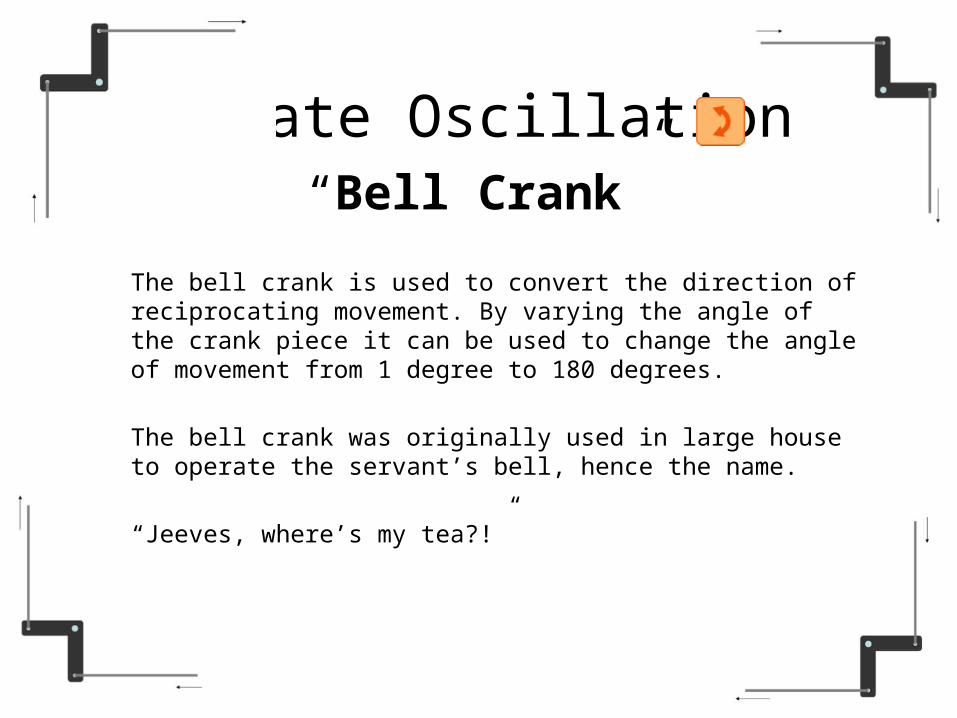
The bell crank is used to convert the direction of reciprocating movement. By varying the angle of the crank piece it can be used to change the angle of movement from 1 degree to 180 degrees.
The bell crank was originally used in large house to operate the servant’s bell, hence the name.
“Jeeves, where’s my tea?!”
Rotate Oscillation“Bell Crank”

Intermittent MotionIntermittent motion is motion which starts and stops regularly. For example, in a cinema projector the film needs to be moved on one frame at a time then held stationary while the light projects it onto the screen. This is usually done with a geneva stop as shown here.Intermittent motion is usually the end result of a mechanism rather than the starting point for conversion.
Motion

Levers are an essential part of many mechanisms. They can be used to change the amount, the strength and the direction of movement. The position of the force and the load are interchangeable and by moving them to different points on the lever, different effects can be produced. The fixed point of the lever about which it moves is known as the fulcrum. In this example the force and the load move in opposite directions. With the force three times closer to the fulcrum them the load lifted is only one third of the force but it move three times as far.
Increase/Decrease Intermittent Motion
“Lever”
First order lever. Like a see-saw or balance, the load and the force are seperated by the fulcrum. As one moves up the orther moves down. The amount and the strength of the movement is proportianal to the distance from the fulcum
Increase/Decrease Intermittent Motion
“Lever”

Second order lever. A wheel barrow is a second order lever. Here the load is between the force and the fulcrum. This uses mechanical advantage to ease lifting of a large weight.
Increase/Decrease Intermittent Motion
“Lever”

Third order lever.Here the force is between the fulcrum and the load. Mechanical advantage is reduced but the movement at the load point is increased.
Increase/Decrease Intermittent Motion
“Lever”

Gears are used to change speed in rotational movement. In the example above the blue gear has eleven teeth and the orange gear has twenty five. To turn the orange gear one full turn the blue gear must turn 25/11 or 2.2727r turns.Notice that as the blue gear turns clockwise the orange gear turns anti-clockwise.In the above example the number of teeth on the orange gear is not divisible by the number of teeth on the blue gear. This is deliberate. If the orange gear had thirty three teeth then every three turns of the blue gear the same teeth would mesh together which could cause excessive wear. By using none divisible numbers the same teeth mesh only every seventeen turns of the blue gear.
“Gears”
Increase/Decrease Intermittent Motion

On the left is a simple pulley. As the rope is pulled down the weight moves up by the same distance.
In the compound pulley on the right the rope is wrapped around two pulleys. As the rope is pulled the weight, this time attached to the lower pulley rather than direct to the rope, moves up slower than the speed that the rope is pulled. Corresponding to this reduction in speed is an increase in the force on the weight.
The amount of increase in the force depends on how many times the rope wraps round the pulleys. By wrapping the rope several times around the pulleys it is easily possible to lift your own weight off the ground!
Reflect Intermittent Motion“Pulley”
Reflect Intermittent Motion
Belt drives are used transfer rotational motion from one place to another.On the left, both pulleys are the same size. Drive can be transfered by friction of the belt on the pulley or, if required, buy using a toothed belt. Chain drives work in a similar way.
By crossing the belt the direction of drive can be changed. On the right two sizes of pulley are used to show how speed of rotation can be changed.
“Belt Drive”

Levers are an essential part of many mechanisms. They can be used to change the amount, the strength and the direction of movement. The position of the force and the load are interchangeable and by moving them to different points on the lever, different effects can be produced. The fixed point of the lever about which it moves is known as the fulcrum. In this example the force and the load move in opposite directions. With the force three times closer to the fulcrum them the load lifted is only one third of the force but it move three times as far.
“Lever”
Reflect Intermittent Motion
First order lever. Like a see-saw or balance, the load and the force are seperated by the fulcrum. As one moves up the orther moves down. The amount and the strength of the movement is proportianal to the distance from the fulcum
“Lever”
Reflect Intermittent Motion

Second order lever. A wheel barrow is a second order lever. Here the load is between the force and the fulcrum. This uses mechanical advantage to ease lifting of a large weight.
“Lever”
Reflect Intermittent Motion

Third order lever.Here the force is between the fulcrum and the load. Mechanical advantage is reduced but the movement at the load point is increased.
“Lever”
Reflect Intermittent Motion

The bell crank is used to convert the direction of reciprocating movement. By varying the angle of the crank piece it can be used to change the angle of movement from 1 degree to 180 degrees.
The bell crank was originally used in large house to operate the servant’s bell, hence the name.
“Jeeves, where’s my tea?!”
“Bell Crank”Rotate intermittent Motion

Irregular MotionIrregular motion is motion which has no obvious pattern to its movement. It is often needed in automata to recreate the movements of living things.
Irregular motion is usually created using a cam or series of camsIrregular motion is not often used as the starting point for a mechanism. It can, however be translated and transormed as shown below.
Motion

Levers are an essential part of many mechanisms. They can be used to change the amount, the strength and the direction of movement. The position of the force and the load are interchangeable and by moving them to different points on the lever, different effects can be produced. The fixed point of the lever about which it moves is known as the fulcrum. In this example the force and the load move in opposite directions. With the force three times closer to the fulcrum them the load lifted is only one third of the force but it move three times as far.
“Lever”
Increase/Decrease Irregular Motion

First order lever. Like a see-saw or balance, the load and the force are seperated by the fulcrum. As one moves up the orther moves down. The amount and the strength of the movement is proportianal to the distance from the fulcum
“Lever”
Increase/Decrease Irregular Motion

Second order lever. A wheel barrow is a second order lever. Here the load is between the force and the fulcrum. This uses mechanical advantage to ease lifting of a large weight.
“Lever”
Increase/Decrease Irregular Motion

Third order lever.Here the force is between the fulcrum and the load. Mechanical advantage is reduced but the movement at the load point is increased.
“Lever”
Increase/Decrease Irregular Motion

On the left is a simple pulley. As the rope is pulled down the weight moves up by the same distance.
In the compound pulley on the right the rope is wrapped around two pulleys. As the rope is pulled the weight, this time attached to the lower pulley rather than direct to the rope, moves up slower than the speed that the rope is pulled. Corresponding to this reduction in speed is an increase in the force on the weight.
The amount of increase in the force depends on how many times the rope wraps round the pulleys. By wrapping the rope several times around the pulleys it is easily possible to lift your own weight off the ground!
Reflect Irregular Motion“Pulley”

Belt drives are used transfer rotational motion from one place to another.On the left, both pulleys are the same size. Drive can be transfered by friction of the belt on the pulley or, if required, buy using a toothed belt. Chain drives work in a similar way.
By crossing the belt the direction of drive can be changed. On the right two sizes of pulley are used to show how speed of rotation can be changed.
“Belt Drive”Reflect Irregular Motion

The bell crank is used to convert the direction of reciprocating movement. By varying the angle of the crank piece it can be used to change the angle of movement from 1 degree to 180 degrees.
The bell crank was originally used in large house to operate the servant’s bell, hence the name.
“Jeeves, where’s my tea?!”
“Bell Crank”Reflect Irregular Motion

The bell crank is used to convert the direction of reciprocating movement. By varying the angle of the crank piece it can be used to change the angle of movement from 1 degree to 180 degrees.
The bell crank was originally used in large house to operate the servant’s bell, hence the name.
“Jeeves, where’s my tea?!”
“Bell Crank”Rotate Irregular Motion


![Interconnected Systems [Kompatibilitätsmodus]](https://img.pdfslide.us/doc/110x75/6241c6f30e4f7279512665fa/interconnected-systems-kompatibilittsmodus.jpg)