Embed Size (px)
Citation preview
9/12/2012
1
ASHRAE 62.2-10
Mechanical Ventilation for Kansas Weatherization Programs
ASHRAE 62.2-10
1 | MECHANICAL VENTILATION – September 2012 www.kansasbuildingscience.com
ASHRAE 62.2-10
By participating in this training, participants will:
• Understand what ASHRAE 62.2 requires, and how it supersedes the old Building Tightness Limit (BTL)
Learning Objectives
supersedes the old Building Tightness Limit (BTL).
• Understand the importance of Indoor Air Quality (IAQ) and the role of mechanical ventilation.
• Understand how to calculate an ASHRAE 62.2-10 continuous fan rate in CFM, and then select a fan capacity and control for an intermittent rate that satisfies the standard.
2 | MECHANICAL VENTILATION – September 2012 www.kansasbuildingscience.com
• Become familiar with different IAQ ventilation strategies.
• Learn to measure exhaust fan flow in CFM.
• Understand how to size fans and install ducts.
9/12/2012
2
ASHRAE 62.2-10
Today’s Agenda
This morning:
◘ Very brief review
◘ C l l ti ASHRAE 62 2 10 ti CFM◘ Calculating ASHRAE 62.2-10 continuous CFM
◘ Further requirements of 62.2 for IAQ
After lunch:
◘ Ventilation strategies
◘ Fans and controls
◘ M i til ti t
3 | MECHANICAL VENTILATION – September 2012 www.kansasbuildingscience.com
◘ Measuring ventilation rates
◘ Hands-on (measuring ventilation rates)
◘ Equivalent intermittent fan rates
◘ Installation of controls, ducts, and hardware
ASHRAE 62.2-10
Scope of 62.2-10
Purpose:
62.2-10 defines the minimum requirements for natural and mechanical ventilation systems to provideand mechanical ventilation systems to provide acceptable indoor air quality (IAQ) in low-rise residential buildings.
ASHRAE 62.2-10 applies to:
• Single and multi-family residential structures 3 stories
4 | MECHANICAL VENTILATION – September 2012 www.kansasbuildingscience.com
g yor fewer above grade, including modular and manufactured housing.
• It does NOT address unvented combustion space heaters.
9/12/2012
3
ASHRAE 62.2-10
ASHRAE Standards and Guidelines
Read the entire ASHRAE 62 2-10 Standard
Preview Popular ASHRAE StandardsYou may preview the following Standards by clicking the links below. Standard 62.1-2010Standard 62.2-2010Standard 90 1-2010
Read the entire ASHRAE 62.2 10 Standardhttp://www.ashrae.org/standards-research--technology/standards--guidelines
5 | MECHANICAL VENTILATION – September 2012 www.kansasbuildingscience.com
Standard 90.1 2010 Standard 90.2-2007Standard 189.1-2011
ASHRAE 62.2-10
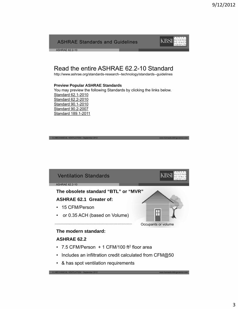
The obsolete standard “BTL” or “MVR”
ASHRAE 62.1 Greater of:
Ventilation Standards
• 15 CFM/Person
• or 0.35 ACH (based on Volume)
The modern standard:
ASHRAE 62 2
Occupants or volume
6 | MECHANICAL VENTILATION – September 2012 www.kansasbuildingscience.com
ASHRAE 62.2
• 7.5 CFM/Person + 1 CFM/100 ft2 floor area
• Includes an infiltration credit calculated from CFM@50
• & has spot ventilation requirements

9/12/2012
4
ASHRAE 62.2-10
Natural ventilation:Why Seal the Leaks at All?
7 | MECHANICAL VENTILATION – September 2012 www.kansasbuildingscience.com
ASHRAE 62.2-10
Does “uncontrolled infiltration” count?
CFMnat = Q50 / N-factor depending on:
G hi l ti• Geographic location
• Building height (increases stack effect)
• Building exposure (to wind)
ASHRAE 62.2-10 uses a “weather factor” for each location. An infiltration credit is
The equivalent “N136‐factors” for KS locations
# of Stories: 1 1.5 2 2.5 3
d 17 7 15 7 14 4 13 4 12 8
8 | MECHANICAL VENTILATION – September 2012 www.kansasbuildingscience.com
allowed for ½ of the post-weatherization CFMNAT when greater than a “default” rate of 2 CFM per 100ft2
Dodge City 17.7 15.7 14.4 13.4 12.8
Goodland 18.1 16.0 14.7 13.7 13.0
Wichita* 20.5 18.1 16.7 15.5 14.8
Topeka 22.6 20.0 18.4 17.1 16.3
Kansas City* 23.2 20.5 18.8 17.5 16.7
9/12/2012
5
ASHRAE 62.2-10
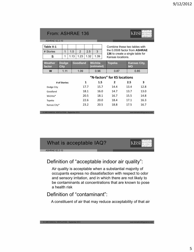
From: ASHRAE 136
Table X-1
# Stories 1 1.5 2 2.5 3
S 1 1 13 1 23 1 32 1 39
Combine these two tables with the 0.0508 factor from ASHRAE 136 to create a single table for Kansas locationsS 1 1.13 1.23 1.32 1.39
Weather factor
Dodge City
Goodland Wichita(estimated)
Topeka Kansas City, MO
W 1.11 1.09 0.96 0.87 0.85
Kansas locations.
“N‐factors” for KS locations
# of Stories: 1 1.5 2 2.5 3
9 | MECHANICAL VENTILATION – September 2012 www.kansasbuildingscience.com
Dodge City 17.7 15.7 14.4 13.4 12.8
Goodland 18.1 16.0 14.7 13.7 13.0
Wichita* 20.5 18.1 16.7 15.5 14.8
Topeka 22.6 20.0 18.4 17.1 16.3
Kansas City* 23.2 20.5 18.8 17.5 16.7
ASHRAE 62.2-10
Definition of “acceptable indoor air quality”:
What is acceptable IAQ?
Air quality is acceptable when a substantial majority of occupants express no dissatisfaction with respect to odor and sensory irritation, and in which there are not likely to be contaminants at concentrations that are known to pose a health risk
Definition of “contaminant”:
10 | MECHANICAL VENTILATION – September 2012 www.kansasbuildingscience.com
Definition of contaminant :A constituent of air that may reduce acceptability of that air
9/12/2012
6
ASHRAE 62.2-10
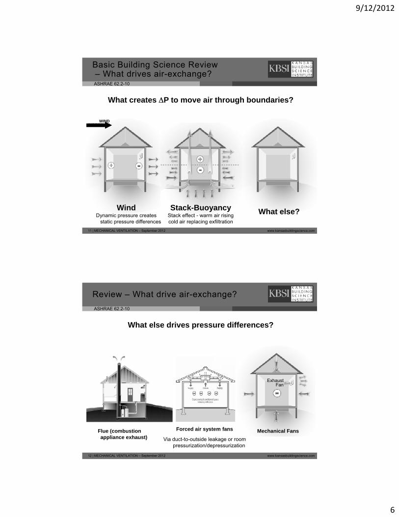
Basic Building Science Review– What drives air-exchange?
What creates P to move air through boundaries?
WIND DIRECTION
11 | MECHANICAL VENTILATION – September 2012 www.kansasbuildingscience.com
Stack-BuoyancyStack effect - warm air risingcold air replacing exfiltration
What else?WindDynamic pressure creates
static pressure differences
ASHRAE 62.2-10
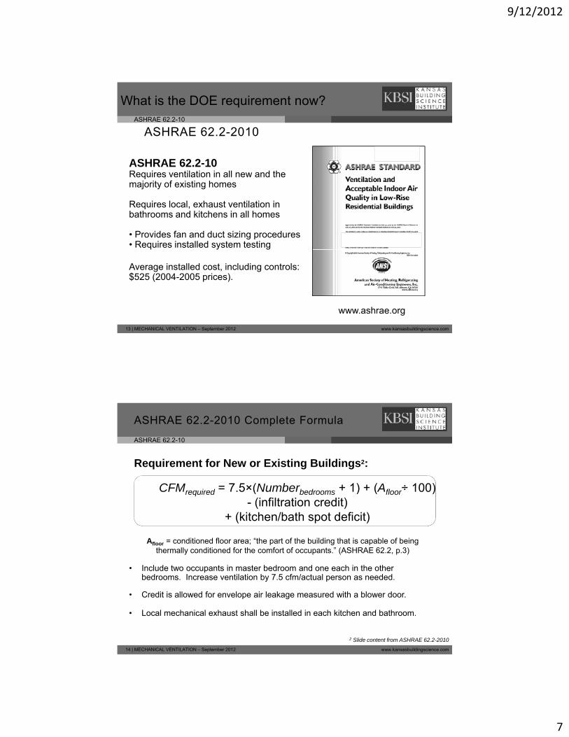
Review – What drive air-exchange?
What else drives pressure differences?
Exhaust Fan
12 | MECHANICAL VENTILATION – September 2012 www.kansasbuildingscience.com
Forced air system fans
Via duct-to-outside leakage or room pressurization/depressurization
Flue (combustion appliance exhaust)
Mechanical Fans
9/12/2012
7
ASHRAE 62.2-10
ASHRAE 62.2-2010
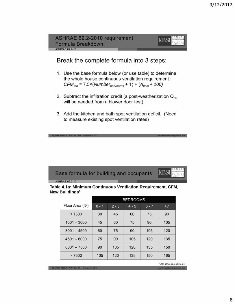
What is the DOE requirement now?
ASHRAE 62.2-10ASHRAE 62.2 10Requires ventilation in all new and the majority of existing homes
Requires local, exhaust ventilation in bathrooms and kitchens in all homes
• Provides fan and duct sizing procedures• Requires installed system testing
13 | MECHANICAL VENTILATION – September 2012 www.kansasbuildingscience.com
www.ashrae.org
Average installed cost, including controls: $525 (2004-2005 prices).
ASHRAE 62.2-10
CFM = 7 5×(Number + 1) + (A ÷ 100)
ASHRAE 62.2-2010 Complete Formula
Requirement for New or Existing Buildings2:
• Include two occupants in master bedroom and one each in the other
CFMrequired = 7.5×(Numberbedrooms + 1) + (Afloor÷ 100) - (infiltration credit)
+ (kitchen/bath spot deficit)
Afloor = conditioned floor area; “the part of the building that is capable of beingthermally conditioned for the comfort of occupants.” (ASHRAE 62.2, p.3)
14 | MECHANICAL VENTILATION – September 2012 www.kansasbuildingscience.com
Include two occupants in master bedroom and one each in the other bedrooms. Increase ventilation by 7.5 cfm/actual person as needed.
• Credit is allowed for envelope air leakage measured with a blower door.
• Local mechanical exhaust shall be installed in each kitchen and bathroom.
2 Slide content from ASHRAE 62.2-2010
9/12/2012
8
ASHRAE 62.2-10
ASHRAE 62.2-2010 requirement Formula Breakdown:
Break the complete formula into 3 steps:
1. Use the base formula below (or use table) to determine the whole house continuous ventilation requirement : CFMfan = 7.5×(Numberbedrooms + 1) + (Afloor ÷ 100)
2. Subtract the infiltration credit (a post-weatherization Q50
will be needed from a blower door test)
15 | MECHANICAL VENTILATION – September 2012 www.kansasbuildingscience.com
will be needed from a blower door test)
3. Add the kitchen and bath spot ventilation deficit. (Need to measure existing spot ventilation rates)
ASHRAE 62.2-10
BEDROOMS
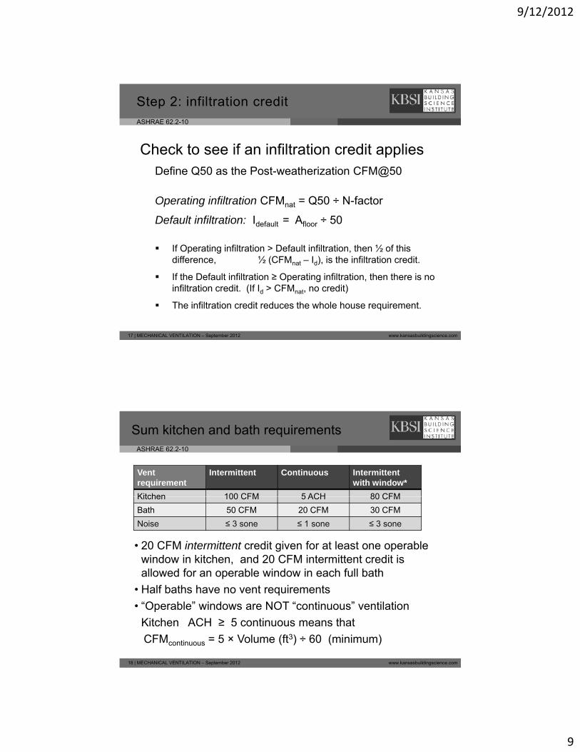
Table 4.1a: Minimum Continuous Ventilation Requirement, CFM, New Buildings1
Base formula for building and occupants
Floor Area (ft2)
BEDROOMS
0 - 1 2 - 3 4 - 5 6 - 7 >7
≤ 1500 30 45 60 75 90
1501 – 3000 45 60 75 90 105
3001 – 4500 60 75 90 105 120
16 | MECHANICAL VENTILATION – September 2012 www.kansasbuildingscience.com
4501 – 6000 75 90 105 120 135
6001 – 7500 90 105 120 135 150
> 7500 105 120 135 150 165
1 ASHRAE 62.2-2010, p 4
9/12/2012
9
ASHRAE 62.2-10
Step 2: infiltration credit
Check to see if an infiltration credit appliesDefine Q50 as the Post weatherization CFM@50Define Q50 as the Post-weatherization CFM@50
Operating infiltration CFMnat = Q50 ÷ N-factor
Default infiltration: Idefault = Afloor ÷ 50
If Operating infiltration > Default infiltration, then ½ of this
17 | MECHANICAL VENTILATION – September 2012 www.kansasbuildingscience.com
difference, ½ (CFMnat – Id), is the infiltration credit.
If the Default infiltration ≥ Operating infiltration, then there is no infiltration credit. (If Id > CFMnat, no credit)
The infiltration credit reduces the whole house requirement.
ASHRAE 62.2-10
Sum kitchen and bath requirements
Ventrequirement
Intermittent Continuous Intermittent with window*
Kitchen 100 CFM 5 ACH 80 CFM
• 20 CFM intermittent credit given for at least one operable window in kitchen, and 20 CFM intermittent credit is allowed for an operable window in each full bath
Kitchen 100 CFM 5 ACH 80 CFM
Bath 50 CFM 20 CFM 30 CFM
Noise ≤ 3 sone ≤ 1 sone ≤ 3 sone
18 | MECHANICAL VENTILATION – September 2012 www.kansasbuildingscience.com
• Half baths have no vent requirements
• “Operable” windows are NOT “continuous” ventilation
Kitchen ACH ≥ 5 continuous means that
CFMcontinuous = 5 × Volume (ft3) ÷ 60 (minimum)
9/12/2012
10
ASHRAE 62.2-10
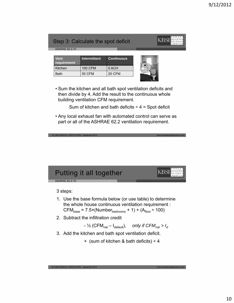
Step 3: Calculate the spot deficit
Ventrequirement
Intermittent Continuous
Kitchen 100 CFM 5 ACH
• Sum the kitchen and all bath spot ventilation deficits and then divide by 4. Add the result to the continuous whole building ventilation CFM requirement.
Kitchen 100 CFM 5 ACH
Bath 50 CFM 20 CFM
19 | MECHANICAL VENTILATION – September 2012 www.kansasbuildingscience.com
Sum of kitchen and bath deficits ÷ 4 = Spot deficit
• Any local exhaust fan with automated control can serve as part or all of the ASHRAE 62.2 ventilation requirement.
ASHRAE 62.2-10
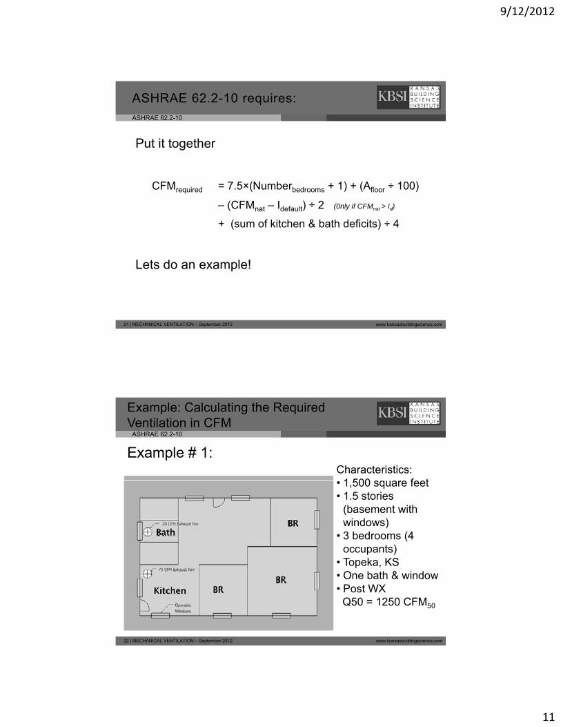
Putting it all together
3 steps:
1. Use the base formula below (or use table) to determine1. Use the base formula below (or use table) to determine the whole house continuous ventilation requirement : CFMbase = 7.5×(Numberbedrooms + 1) + (Afloor ÷ 100)
2. Subtract the infiltration credit
- ½ (CFMnat – Idefault), only if CFMnat > Id
3. Add the kitchen and bath spot ventilation deficit.
20 | MECHANICAL VENTILATION – September 2012 www.kansasbuildingscience.com
3. Add the kitchen and bath spot ventilation deficit.
+ (sum of kitchen & bath deficits) ÷ 4
9/12/2012
11
ASHRAE 62.2-10
ASHRAE 62.2-10 requires:
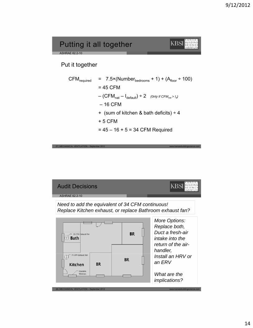
Put it together
CFMrequired = 7.5×(Numberbedrooms + 1) + (Afloor ÷ 100)
– (CFMnat – Idefault) ÷ 2 (0nly if CFMnat > Id)
+ (sum of kitchen & bath deficits) ÷ 4
21 | MECHANICAL VENTILATION – September 2012 www.kansasbuildingscience.com
Lets do an example!
ASHRAE 62.2-10
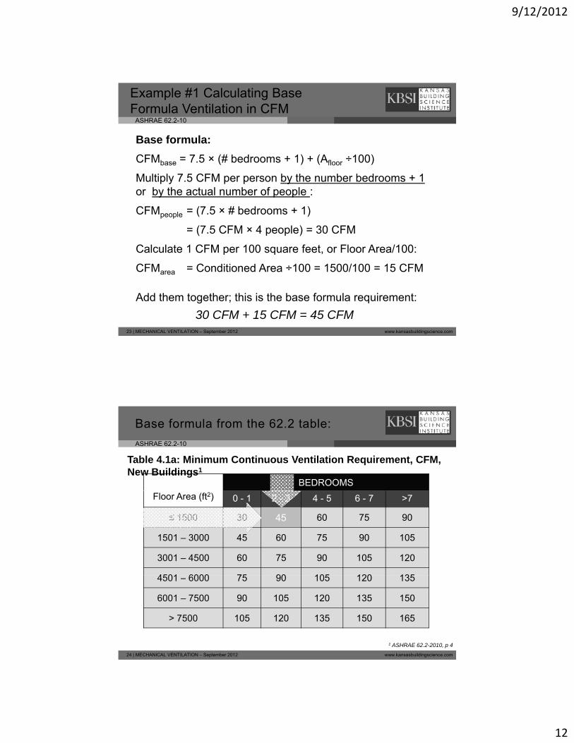
Example: Calculating the Required Ventilation in CFM
Characteristics:1 500 f t
Example # 1:
• 1,500 square feet • 1.5 stories
(basement with windows)
• 3 bedrooms (4 occupants)
• Topeka KS
22 | MECHANICAL VENTILATION – September 2012 www.kansasbuildingscience.com
• Topeka, KS• One bath & window• Post WX Q50 = 1250 CFM50
9/12/2012
12
ASHRAE 62.2-10
Example #1 Calculating Base Formula Ventilation in CFM
Base formula:
CFMbase = 7.5 × (# bedrooms + 1) + (Afloor ÷100)
Multiply 7.5 CFM per person by the number bedrooms + 1 or by the actual number of people :
CFMpeople = (7.5 × # bedrooms + 1)
= (7.5 CFM × 4 people) = 30 CFM
Calculate 1 CFM per 100 square feet, or Floor Area/100:
23 | MECHANICAL VENTILATION – September 2012 www.kansasbuildingscience.com
Calculate 1 CFM per 100 square feet, or Floor Area/100:
CFMarea = Conditioned Area ÷100 = 1500/100 = 15 CFM
Add them together; this is the base formula requirement:
30 CFM + 15 CFM = 45 CFM
ASHRAE 62.2-10
BEDROOMS
Table 4.1a: Minimum Continuous Ventilation Requirement, CFM, New Buildings1
Base formula from the 62.2 table:
Floor Area (ft2) 0 - 1 2 - 3 4 - 5 6 - 7 >7
≤ 1500 30 45 60 75 90
1501 – 3000 45 60 75 90 105
3001 – 4500 60 75 90 105 120
4501 6000 75 90 105 120 135
45
24 | MECHANICAL VENTILATION – September 2012 www.kansasbuildingscience.com
4501 – 6000 75 90 105 120 135
6001 – 7500 90 105 120 135 150
> 7500 105 120 135 150 165
1 ASHRAE 62.2-2010, p 4
9/12/2012
13
ASHRAE 62.2-10
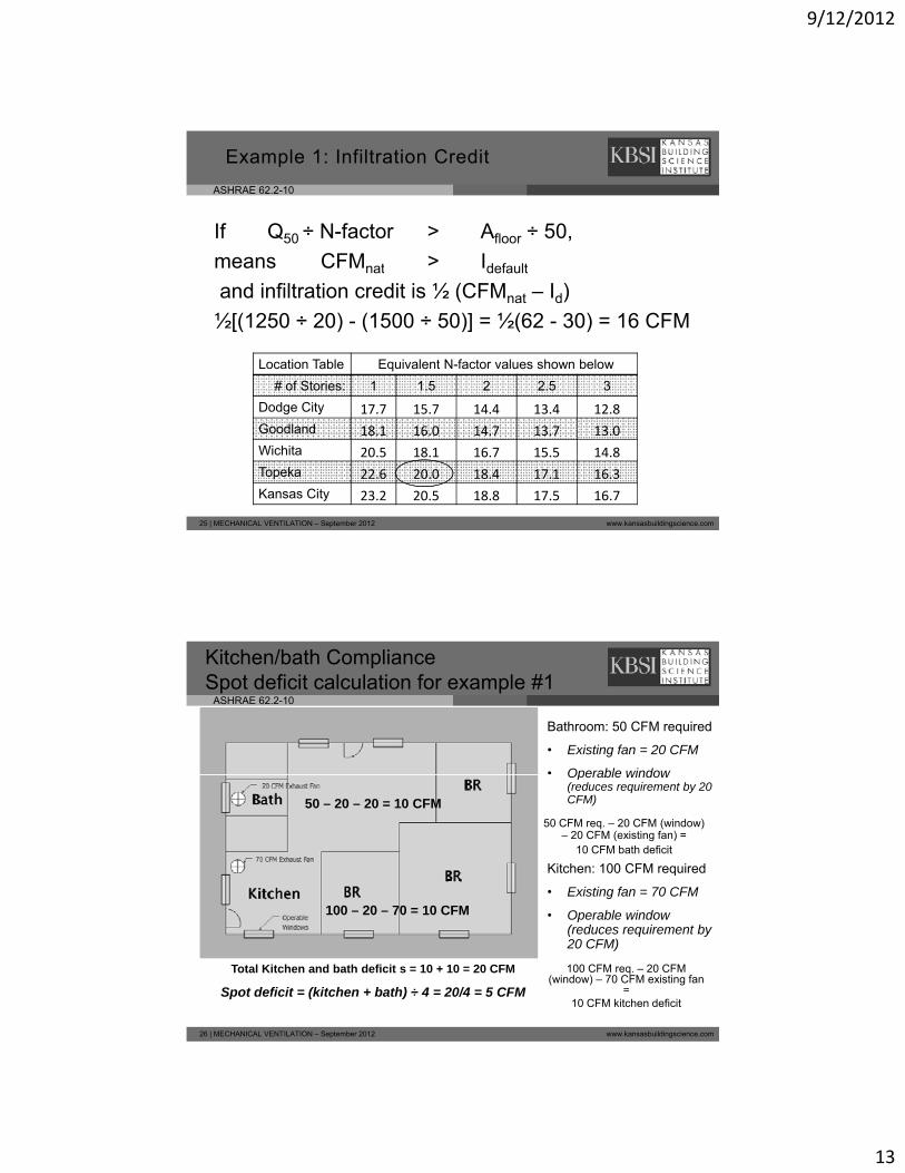
Example 1: Infiltration Credit
If Q50 ÷ N-factor > Afloor ÷ 50,
means CFM t > Id f lt
Location Table Equivalent N-factor values shown below
# of Stories: 1 1.5 2 2.5 3
means CFMnat > Idefault
and infiltration credit is ½ (CFMnat – Id)
½[(1250 ÷ 20) - (1500 ÷ 50)] = ½(62 - 30) = 16 CFM
25 | MECHANICAL VENTILATION – September 2012 www.kansasbuildingscience.com
Dodge City 17.7 15.7 14.4 13.4 12.8
Goodland 18.1 16.0 14.7 13.7 13.0
Wichita 20.5 18.1 16.7 15.5 14.8
Topeka 22.6 20.0 18.4 17.1 16.3
Kansas City 23.2 20.5 18.8 17.5 16.7
ASHRAE 62.2-10
Kitchen/bath ComplianceSpot deficit calculation for example #1
Bathroom: 50 CFM required
• Existing fan = 20 CFM
• Operable windowOperable window (reduces requirement by 20 CFM)
Kitchen: 100 CFM required
• Existing fan = 70 CFM
50 CFM req. – 20 CFM (window) – 20 CFM (existing fan) =
10 CFM bath deficit
50 – 20 – 20 = 10 CFM
100 20 70 = 10 CFM
26 | MECHANICAL VENTILATION – September 2012 www.kansasbuildingscience.com
• Operable window (reduces requirement by 20 CFM)
100 CFM req. – 20 CFM (window) – 70 CFM existing fan
= 10 CFM kitchen deficit
100 – 20 – 70 = 10 CFM
Total Kitchen and bath deficit s = 10 + 10 = 20 CFM
Spot deficit = (kitchen + bath) ÷ 4 = 20/4 = 5 CFM
9/12/2012
14
ASHRAE 62.2-10
Putting it all together
Put it together
CFMrequired = 7.5×(Numberbedrooms + 1) + (Afloor ÷ 100)
= 45 CFM
– (CFMnat – Idefault) ÷ 2 (0nly if CFMnat > Id)
– 16 CFM
( f kit h & b th d fi it ) 4
27 | MECHANICAL VENTILATION – September 2012 www.kansasbuildingscience.com
+ (sum of kitchen & bath deficits) ÷ 4
+ 5 CFM
= 45 – 16 + 5 = 34 CFM Required
ASHRAE 62.2-10
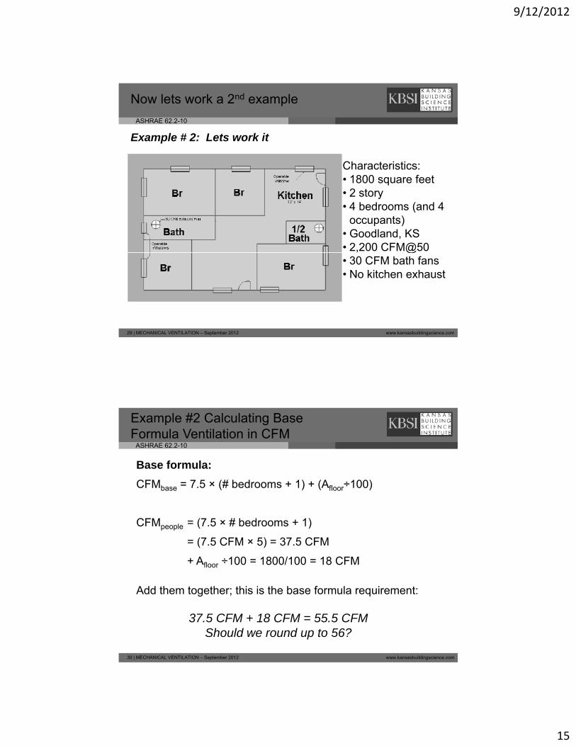
Audit Decisions
Need to add the equivalent of 34 CFM continuous!Replace Kitchen exhaust, or replace Bathroom exhaust fan?
More Options:Replace both,Duct a fresh-air intake into the return of the air-handler,
28 | MECHANICAL VENTILATION – September 2012 www.kansasbuildingscience.com
Install an HRV or an ERV
What are the implications?
9/12/2012
15
ASHRAE 62.2-10
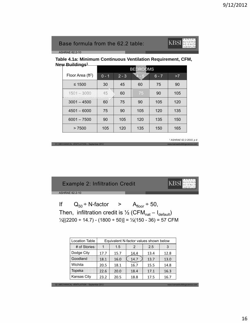
Now lets work a 2nd example
Characteristics:
Example # 2: Lets work it
Characteristics:• 1800 square feet • 2 story• 4 bedrooms (and 4
occupants)• Goodland, KS• 2,200 CFM@50
29 | MECHANICAL VENTILATION – September 2012 www.kansasbuildingscience.com
@• 30 CFM bath fans• No kitchen exhaust
ASHRAE 62.2-10
Example #2 Calculating Base Formula Ventilation in CFM
Base formula:
CFMbase = 7.5 × (# bedrooms + 1) + (Afloor÷100)
CFMpeople = (7.5 × # bedrooms + 1)
= (7.5 CFM × 5) = 37.5 CFM
+ Afloor ÷100 = 1800/100 = 18 CFM
30 | MECHANICAL VENTILATION – September 2012 www.kansasbuildingscience.com
Add them together; this is the base formula requirement:
37.5 CFM + 18 CFM = 55.5 CFMShould we round up to 56?
9/12/2012
16
ASHRAE 62.2-10
BEDROOMS
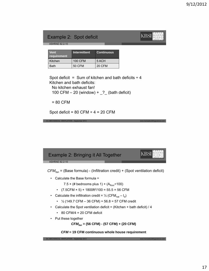
Table 4.1a: Minimum Continuous Ventilation Requirement, CFM, New Buildings1
Base formula from the 62.2 table:
Floor Area (ft2) 0 - 1 2 - 3 4 - 5 6 - 7 >7
≤ 1500 30 45 60 75 90
1501 – 3000 45 60 75 90 105
3001 – 4500 60 75 90 105 120
4501 6000 75 90 105 120 135
75
31 | MECHANICAL VENTILATION – September 2012 www.kansasbuildingscience.com
4501 – 6000 75 90 105 120 135
6001 – 7500 90 105 120 135 150
> 7500 105 120 135 150 165
1 ASHRAE 62.2-2010, p 4
ASHRAE 62.2-10
Example 2: Infiltration Credit
If Q50 ÷ N-factor > Afloor ÷ 50,
Then infiltration credit is ½ (CFM t – Id f lt)
Location Table Equivalent N-factor values shown below
# of Stories: 1 1.5 2 2.5 3
Then, infiltration credit is ½ (CFMnat Idefault)½[(2200 ÷ 14.7) - (1800 ÷ 50)] = ½(150 - 36) = 57 CFM
32 | MECHANICAL VENTILATION – September 2012 www.kansasbuildingscience.com
Dodge City 17.7 15.7 14.4 13.4 12.8
Goodland 18.1 16.0 14.7 13.7 13.0
Wichita 20.5 18.1 16.7 15.5 14.8
Topeka 22.6 20.0 18.4 17.1 16.3
Kansas City 23.2 20.5 18.8 17.5 16.7
9/12/2012
17
ASHRAE 62.2-10
Example 2: Spot deficit
Ventrequirement
Intermittent Continuous
Kitchen 100 CFM 5 ACH
Spot deficit = Sum of kitchen and bath deficits ÷ 4Kitchen and bath deficits:
No kitchen exhaust fan!100 CFM 20 (window) + ? (bath deficit)
Kitchen 100 CFM 5 ACH
Bath 50 CFM 20 CFM
33 | MECHANICAL VENTILATION – September 2012 www.kansasbuildingscience.com
100 CFM – 20 (window) + _?_ (bath deficit)
= 80 CFM
Spot deficit = 80 CFM ÷ 4 = 20 CFM
ASHRAE 62.2-10
Example 2: Bringing it All Together
CFMfan = (Base formula) - (Infiltration credit) + (Spot ventilation deficit)
• Calculate the Base formula =Calculate the Base formula
7.5 × (# bedrooms plus 1) + (Afloor÷100)
• (7.5CFM × 5) + 1800ft2/100 = 55.5 = 56 CFM
• Calculate the infiltration credit = ½ (CFMnat – Id)
• ½ (149.7 CFM – 36 CFM) = 56.8 = 57 CFM credit
• Calculate the Spot ventilation deficit = (Kitchen + bath deficit) / 4
34 | MECHANICAL VENTILATION – September 2012 www.kansasbuildingscience.com
• 80 CFM/4 = 20 CFM deficit
• Put these together
CFMfan = (56 CFM) - (57 CFM) + (20 CFM)
CFM = 19 CFM continuous whole house requirement
9/12/2012
18
ASHRAE 62.2-10
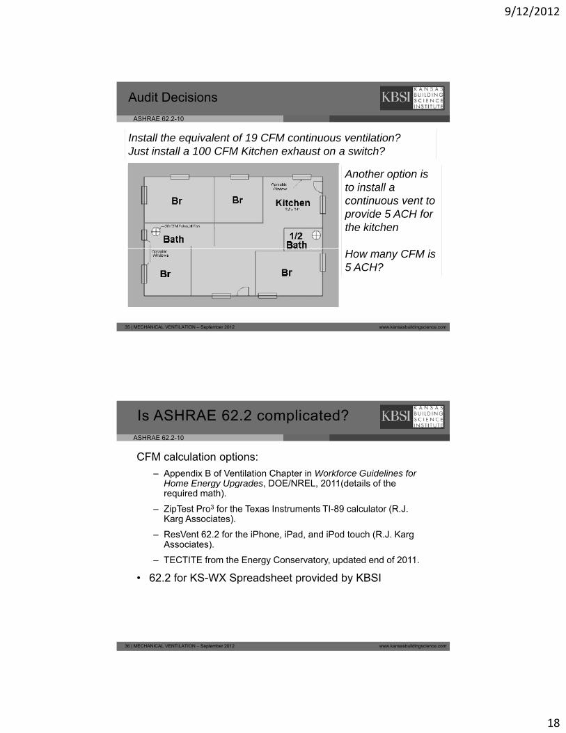
Audit Decisions
Install the equivalent of 19 CFM continuous ventilation?Just install a 100 CFM Kitchen exhaust on a switch?
Another option is to install a continuous vent to provide 5 ACH for the kitchen
35 | MECHANICAL VENTILATION – September 2012 www.kansasbuildingscience.com
How many CFM is 5 ACH?
ASHRAE 62.2-10
CFM calculation options:
– Appendix B of Ventilation Chapter in Workforce Guidelines for Home Energy Upgrades DOE/NREL 2011(details of the
Is ASHRAE 62.2 complicated?
Home Energy Upgrades, DOE/NREL, 2011(details of the required math).
– ZipTest Pro3 for the Texas Instruments TI-89 calculator (R.J. Karg Associates).
– ResVent 62.2 for the iPhone, iPad, and iPod touch (R.J. Karg Associates).
– TECTITE from the Energy Conservatory, updated end of 2011.
36 | MECHANICAL VENTILATION – September 2012 www.kansasbuildingscience.com
• 62.2 for KS-WX Spreadsheet provided by KBSI
9/12/2012
19
ASHRAE 62.2-10
Beyond Whole House CFM Ventilation Requirements
Remember, ASHRAE 62.2 2010 includes:
• Spot ventilation requirements
Att h d t b d t l l d f li i• Attached garages must be adequately sealed from living space to prevent migration of contaminants
• Clothes driers and all exhaust vents must exit directly outside
• All duct joints outside conditioned space must be sealed
• Air filtration with a accessible MERV 6 or better in all ducted systems
37 | MECHANICAL VENTILATION – September 2012 www.kansasbuildingscience.com
• Fan SONE rating requirements must be met
• Exhaust fans and branch duct systems must have back-draft dampers
• Fan flow rates must be measured / verified
ASHRAE 62.2-10
Mechanical Ventilation for Kansas Weatherization Programs - Part 2
ASHRAE 62.2-10
38 | MECHANICAL VENTILATION – September 2012 www.kansasbuildingscience.com
ASHRAE 62.2 10
9/12/2012
20
ASHRAE 62.2-10
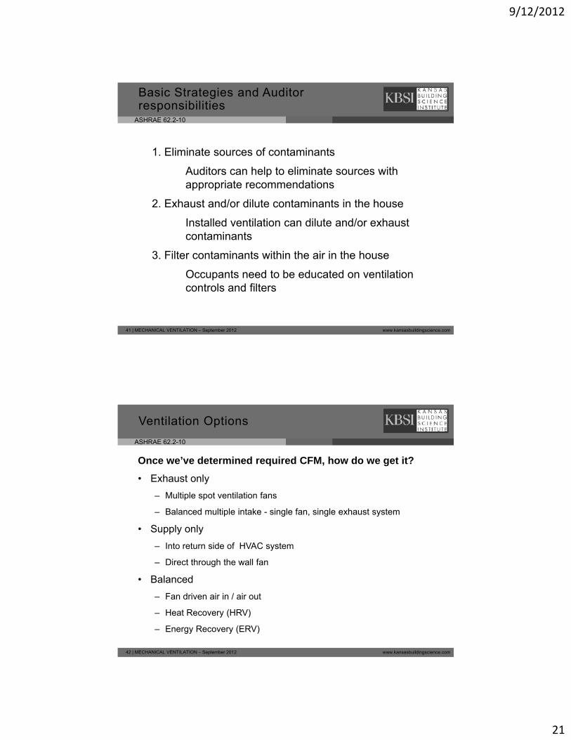
Summary of “acceptable indoor air quality”:
What is acceptable IAQ?
Air quality is acceptable when a majority of occupants express no dissatisfaction from odors and contaminants are not likely to pose a health risk.
Examples of “contaminants”:Odors – Chemicals, off‐gassing of paint, furniture, carpet
39 | MECHANICAL VENTILATION – September 2012 www.kansasbuildingscience.com
Sensory irritation – Pollen, dust, pet dander
Health impact – Carbon monoxide, excess moisture (mold dust mites etc), asthma triggers
ASHRAE 62.2-10
Do any occupants have respiratory/asthma, or air quality related health problems?
Basic Strategies for good IAQ
q y p
Yes No
The best ventilation strategy for IAQ depends upon the client, the house, and site-specific detail.
Three basic strategies:
40 | MECHANICAL VENTILATION – September 2012 www.kansasbuildingscience.com
1. Eliminate sources of contaminants
2. Exhaust and/or dilute contaminants in the house
3. Filter contaminants in the house
9/12/2012
21
ASHRAE 62.2-10
1. Eliminate sources of contaminants
Basic Strategies and Auditor responsibilities
Auditors can help to eliminate sources with appropriate recommendations
2. Exhaust and/or dilute contaminants in the house
Installed ventilation can dilute and/or exhaust contaminants
41 | MECHANICAL VENTILATION – September 2012 www.kansasbuildingscience.com
3. Filter contaminants within the air in the house
Occupants need to be educated on ventilation controls and filters
ASHRAE 62.2-10
Once we’ve determined required CFM, how do we get it?
• Exhaust only
Ventilation Options
– Multiple spot ventilation fans
– Balanced multiple intake - single fan, single exhaust system
• Supply only
– Into return side of HVAC system
– Direct through the wall fan
42 | MECHANICAL VENTILATION – September 2012 www.kansasbuildingscience.com
• Balanced
– Fan driven air in / air out
– Heat Recovery (HRV)
– Energy Recovery (ERV)
9/12/2012
22
ASHRAE 62.2-10
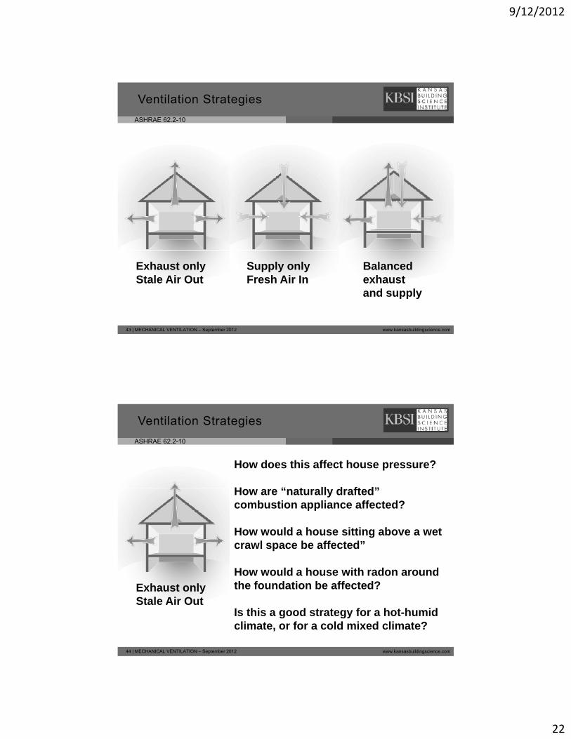
Ventilation Strategies
43 | MECHANICAL VENTILATION – September 2012 www.kansasbuildingscience.com
Supply only Fresh Air In
Exhaust only Stale Air Out
Balanced exhaust and supply
ASHRAE 62.2-10
How does this affect house pressure?
H “ t ll d ft d”
Ventilation Strategies
How are “naturally drafted” combustion appliance affected?
How would a house sitting above a wet crawl space be affected”
How would a house with radon around
44 | MECHANICAL VENTILATION – September 2012 www.kansasbuildingscience.com
How would a house with radon around the foundation be affected?
Is this a good strategy for a hot-humid climate, or for a cold mixed climate?
Exhaust only Stale Air Out
9/12/2012
23
ASHRAE 62.2-10
Ventilation Strategies
Advantages: Disadvantages:____________________________________________________________
______________________________________________________________________________
45 | MECHANICAL VENTILATION – September 2012 www.kansasbuildingscience.com
Supply only Fresh Air In
__________
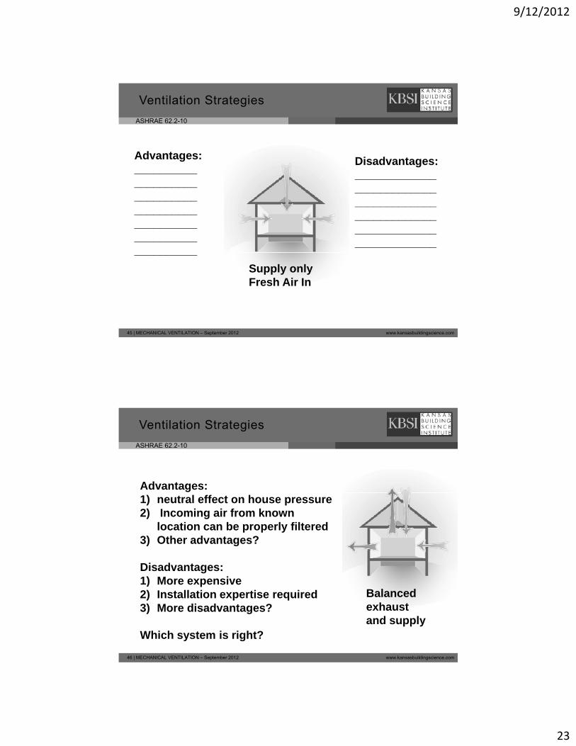
ASHRAE 62.2-10
Ventilation Strategies
Advantages:1) neutral effect on house pressure2) Incoming air from known
location can be properly filtered3) Other advantages?
Disadvantages:1) M i
46 | MECHANICAL VENTILATION – September 2012 www.kansasbuildingscience.com
1) More expensive2) Installation expertise required3) More disadvantages?
Which system is right?
Balanced exhaust and supply
9/12/2012
24
ASHRAE 62.2-10
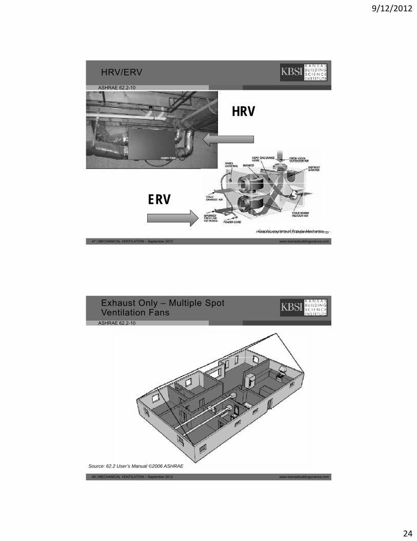
HRV/ERV
HRV
47 | MECHANICAL VENTILATION – September 2012 www.kansasbuildingscience.com
Photo courtesy of The US Department of Energy
ERV
Graphic courtesy of Popular Mechanics
ASHRAE 62.2-10
Exhaust Only – Multiple Spot Ventilation Fans
48 | MECHANICAL VENTILATION – September 2012 www.kansasbuildingscience.com
Source: 62.2 User’s Manual ©2006 ASHRAE
9/12/2012
25
ASHRAE 62.2-10
Exhaust Only – Single System, Multiple Intakes
49 | MECHANICAL VENTILATION – September 2012 www.kansasbuildingscience.com
Source: 62.2 User’s Manual ©2006 ASHRAE
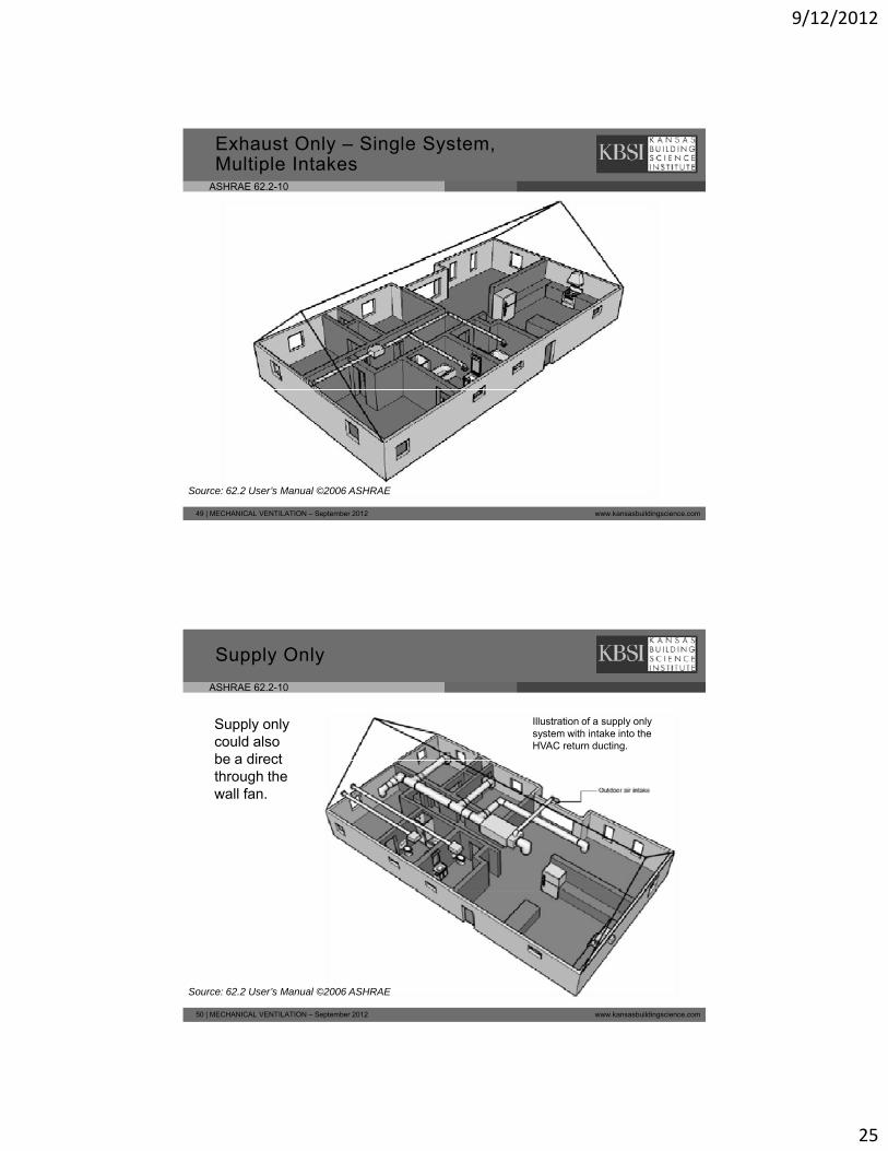
ASHRAE 62.2-10
Supply Only
Illustration of a supply only system with intake into the HVAC return ducting.
Supply only could also be a directbe a direct through the wall fan.
50 | MECHANICAL VENTILATION – September 2012 www.kansasbuildingscience.com
Source: 62.2 User’s Manual ©2006 ASHRAE
9/12/2012
26
ASHRAE 62.2-10
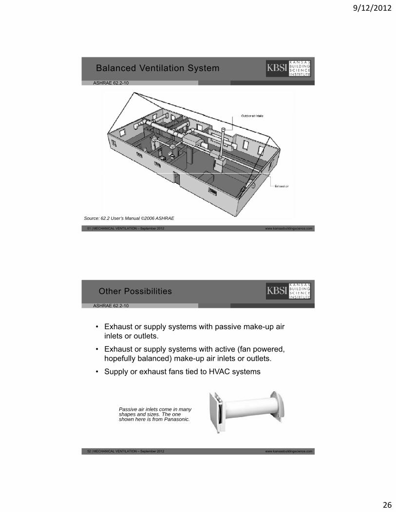
Balanced Ventilation System
51 | MECHANICAL VENTILATION – September 2012 www.kansasbuildingscience.com
Source: 62.2 User’s Manual ©2006 ASHRAE
ASHRAE 62.2-10
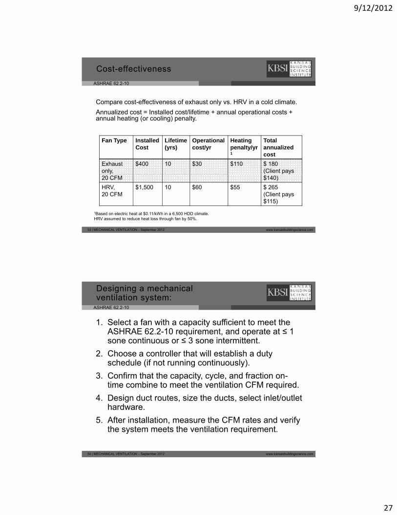
• Exhaust or supply systems with passive make-up air inlets or outlets.
Other Possibilities
inlets or outlets.
• Exhaust or supply systems with active (fan powered, hopefully balanced) make-up air inlets or outlets.
• Supply or exhaust fans tied to HVAC systems
52 | MECHANICAL VENTILATION – September 2012 www.kansasbuildingscience.com
Passive air inlets come in many shapes and sizes. The one shown here is from Panasonic.
9/12/2012
27
ASHRAE 62.2-10
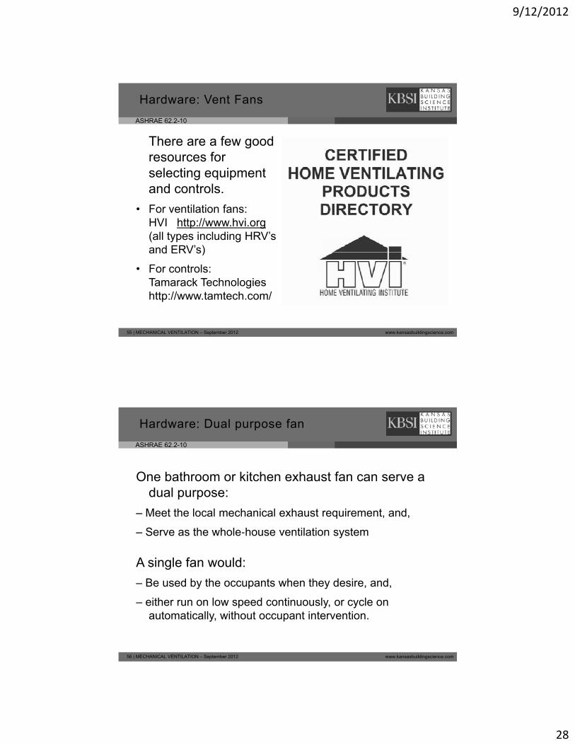
Compare cost-effectiveness of exhaust only vs. HRV in a cold climate.
Annualized cost = Installed cost/lifetime + annual operational costs + l h ti ( li ) lt
Cost-effectiveness
annual heating (or cooling) penalty.
Fan Type Installed Cost
Lifetime(yrs)
Operational cost/yr
Heating penalty/yr1
Total annualized cost
Exhaustonly,
$400 10 $30 $110 $ 180(Client pays
53 | MECHANICAL VENTILATION – September 2012 www.kansasbuildingscience.com
20 CFM $140)
HRV, 20 CFM
$1,500 10 $60 $55 $ 265(Client pays $115)
1Based on electric heat at $0.11/kWh in a 6,500 HDD climate.HRV assumed to reduce heat loss through fan by 50%.
ASHRAE 62.2-10
Designing a mechanical ventilation system:
1. Select a fan with a capacity sufficient to meet the ASHRAE 62.2-10 requirement, and operate at ≤ 1 sone continuous or ≤ 3 sone intermittentsone continuous or ≤ 3 sone intermittent.
2. Choose a controller that will establish a duty schedule (if not running continuously).
3. Confirm that the capacity, cycle, and fraction on-time combine to meet the ventilation CFM required.
4 Design duct routes size the ducts select inlet/outlet
54 | MECHANICAL VENTILATION – September 2012 www.kansasbuildingscience.com
4. Design duct routes, size the ducts, select inlet/outlet hardware.
5. After installation, measure the CFM rates and verify the system meets the ventilation requirement.
9/12/2012
28
ASHRAE 62.2-10
Hardware: Vent Fans
There are a few good resources for selecting equipment and controls.
• For ventilation fans: HVI http://www.hvi.org(all types including HRV’s and ERV’s)
55 | MECHANICAL VENTILATION – September 2012 www.kansasbuildingscience.com
and ERV s)
• For controls: Tamarack Technologies http://www.tamtech.com/
ASHRAE 62.2-10
Hardware: Dual purpose fan
One bathroom or kitchen exhaust fan can serve a dual purpose:dual purpose:
– Meet the local mechanical exhaust requirement, and,
– Serve as the whole‐house ventilation system
A single fan would:
56 | MECHANICAL VENTILATION – September 2012 www.kansasbuildingscience.com
– Be used by the occupants when they desire, and,
– either run on low speed continuously, or cycle on automatically, without occupant intervention.
9/12/2012
29
ASHRAE 62.2-10
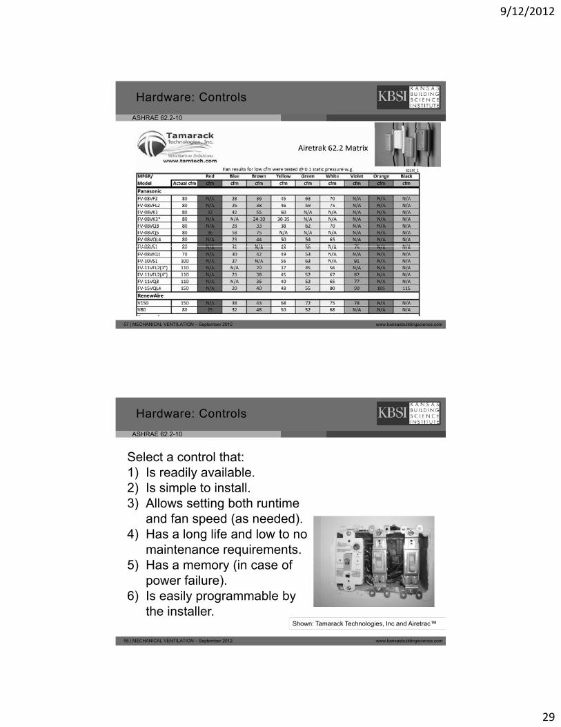
Hardware: Controls
57 | MECHANICAL VENTILATION – September 2012 www.kansasbuildingscience.com
ASHRAE 62.2-10
Select a control that: 1) Is readily available.
Hardware: Controls
2) Is simple to install.3) Allows setting both runtime
and fan speed (as needed).4) Has a long life and low to no
maintenance requirements.5) Has a memory (in case of
58 | MECHANICAL VENTILATION – September 2012 www.kansasbuildingscience.com
Shown: Tamarack Technologies, Inc and Airetrac™
5) Has a memory (in case of power failure).
6) Is easily programmable by the installer.
9/12/2012
30
ASHRAE 62.2-10
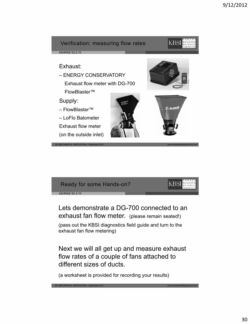
Verification: measuring flow rates
Exhaust:
– ENERGY CONSERVATORY
Exhaust flow meter with DG-700
FlowBlaster™
Supply:
– FlowBlaster™
59 | MECHANICAL VENTILATION – September 2012 www.kansasbuildingscience.com
– FlowBlaster
– LoFlo Balometer
Exhaust flow meter
(on the outside inlet)
ASHRAE 62.2-10
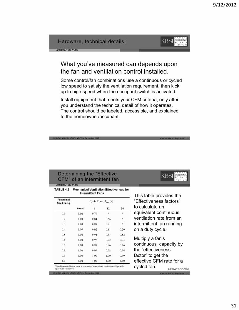
Ready for some Hands-on?
Lets demonstrate a DG-700 connected to an h t f fl texhaust fan flow meter. (please remain seated!)
(pass out the KBSI diagnostics field guide and turn to the exhaust fan flow metering)
Next we will all get up and measure exhaust
60 | MECHANICAL VENTILATION – September 2012 www.kansasbuildingscience.com
e t e a get up a d easu e e austflow rates of a couple of fans attached to different sizes of ducts.
(a worksheet is provided for recording your results)
9/12/2012
31
ASHRAE 62.2-10
Hardware, technical details!
What you’ve measured can depends upon th f d til ti t l i t ll dthe fan and ventilation control installed.Some control/fan combinations use a continuous or cycled low speed to satisfy the ventilation requirement, then kick up to high speed when the occupant switch is activated.
Install equipment that meets your CFM criteria, only after you understand the technical detail of how it operates
61 | MECHANICAL VENTILATION – September 2012 www.kansasbuildingscience.com
you understand the technical detail of how it operates. The control should be labeled, accessible, and explained to the homeowner/occupant.
ASHRAE 62.2-10
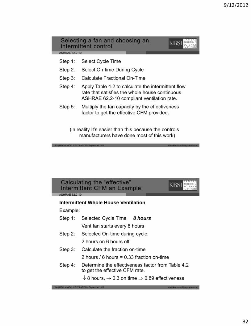
Determining the “Effective CFM” of an intermittent fan
This table provides the “Effectiveness factors” to calculate an equivalent continuous ventilation rate from an intermittent fan running on a duty cycle.
Multiply a fan’s
62 | MECHANICAL VENTILATION – September 2012 www.kansasbuildingscience.com
u t p y a a scontinuous capacity by the “effectiveness factor” to get the effective CFM rate for a cycled fan.
ASHRAE 62.2-2010
9/12/2012
32
ASHRAE 62.2-10
Step 1: Select Cycle Time
Step 2: Select On‐time During Cycle
Selecting a fan and choosing an intermittent control
Step 3: Calculate Fractional On‐Time
Step 4: Apply Table 4.2 to calculate the intermittent flow rate that satisfies the whole house continuous ASHRAE 62.2-10 compliant ventilation rate.
Step 5: Multiply the fan capacity by the effectiveness
63 | MECHANICAL VENTILATION – September 2012 www.kansasbuildingscience.com
factor to get the effective CFM provided.
(in reality It’s easier than this because the controls manufacturers have done most of this work)
ASHRAE 62.2-10
Intermittent Whole House Ventilation
Example:
Calculating the “effective” Intermittent CFM an Example:
Step 1: Selected Cycle Time 8 hours
Vent fan starts every 8 hours
Step 2: Selected On-time during cycle:
2 hours on 6 hours off
Step 3: Calculate the fraction on-time
64 | MECHANICAL VENTILATION – September 2012 www.kansasbuildingscience.com
2 hours / 6 hours = 0.33 fraction on-time
Step 4: Determine the effectiveness factor from Table 4.2 to get the effective CFM rate.
8 hours, 0.3 on time 0.89 effectiveness
9/12/2012
33
ASHRAE 62.2-10
Intermittent Whole House Ventilation
Example continued:
Calculating the “effective” Intermittent CFM an Example:
Step 4: Multiply the fan capacity by the effectiveness factor to get the effective CFM rate.
8 hours, 0.3 on time 0.89 effectiveness
Step 5: Multiply the fan rated capacity by the effectiveness factor to get the effective CFM rate provided.
65 | MECHANICAL VENTILATION – September 2012 www.kansasbuildingscience.com
CFMeffective = CFMrated x Effectiveness factor
For example if we selected an 80 CFM fan, the effective rate provided will be 80 x 0.89 = 71 CFM
ASHRAE 62.2-10
Designing ducts, guidelines and recommendations
1) Exhaust flow must exit directly outside.2) Use short, straight, well-sealed ducts.3) Use large diameter duct.4) Use insulated ducts when the route goes outside
the thermal boundary.5) Use 2 to 3 feet of straight pipe before and after
elbows.6) Use hard duct elbows for sharp bends
66 | MECHANICAL VENTILATION – September 2012 www.kansasbuildingscience.com
6) Use hard duct elbows for sharp bends7) Use low-friction supply diffusers and return grilles.8) Terminations must keep animals out.9) Follow manufacturer specs and installation
instructions.
9/12/2012
34
ASHRAE 62.2-10
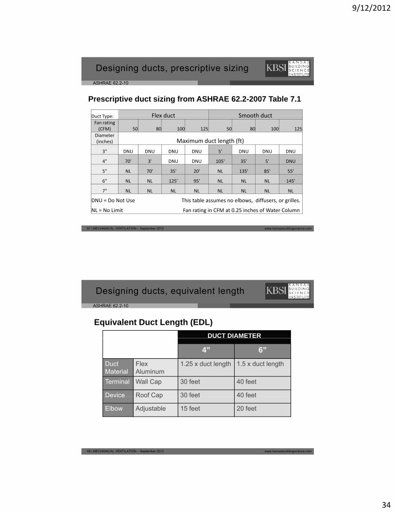
Designing ducts, prescriptive sizing
Prescriptive duct sizing from ASHRAE 62.2-2007 Table 7.1
D t T Flex duct Smooth ductDuct Type: Flex duct Smooth ductFan rating (CFM) 50 80 100 125 50 80 100 125
Diameter(inches) Maximum duct length (ft)
3" DNU DNU DNU DNU 5' DNU DNU DNU
4" 70' 3' DNU DNU 105' 35' 5' DNU
5" NL 70' 35' 20' NL 135' 85' 55'
67 | MECHANICAL VENTILATION – September 2012 www.kansasbuildingscience.com
6" NL NL 125' 95' NL NL NL 145'
7" NL NL NL NL NL NL NL NL
DNU = Do Not Use This table assumes no elbows, diffusers, or grilles.
NL = No Limit Fan rating in CFM at 0.25 inches of Water Column
ASHRAE 62.2-10
Designing ducts, equivalent length
Equivalent Duct Length (EDL)
DUCT DIAMETER
4” 6”
Duct Material
Flex Aluminum
1.25 x duct length 1.5 x duct length
Terminal Wall Cap 30 feet 40 feet
Device Roof Cap 30 feet 40 feet
68 | MECHANICAL VENTILATION – September 2012 www.kansasbuildingscience.com
Device Roof Cap 30 feet 40 feet
Elbow Adjustable 15 feet 20 feet
9/12/2012
35
ASHRAE 62.2-10
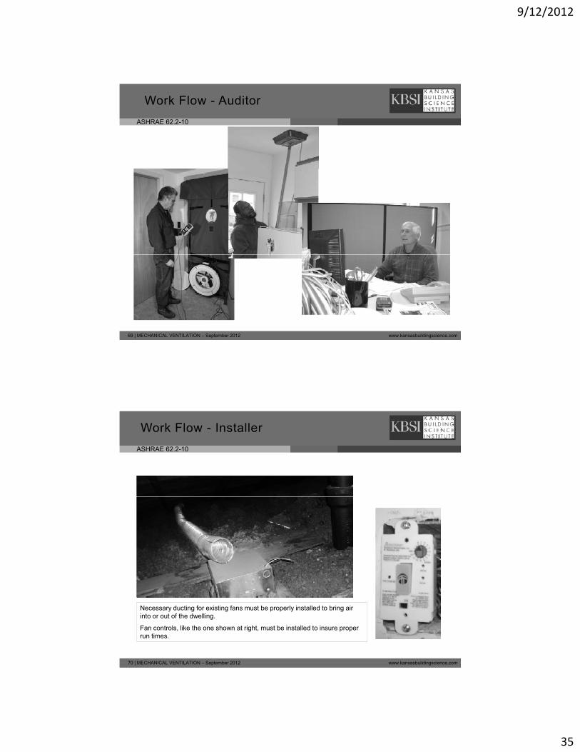
Work Flow - Auditor
69 | MECHANICAL VENTILATION – September 2012 www.kansasbuildingscience.com
ASHRAE 62.2-10
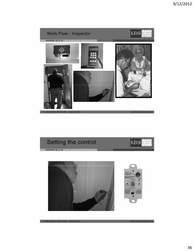
Work Flow - Installer
70 | MECHANICAL VENTILATION – September 2012 www.kansasbuildingscience.com
Necessary ducting for existing fans must be properly installed to bring air into or out of the dwelling.
Fan controls, like the one shown at right, must be installed to insure proper run times.
9/12/2012
36
ASHRAE 62.2-10
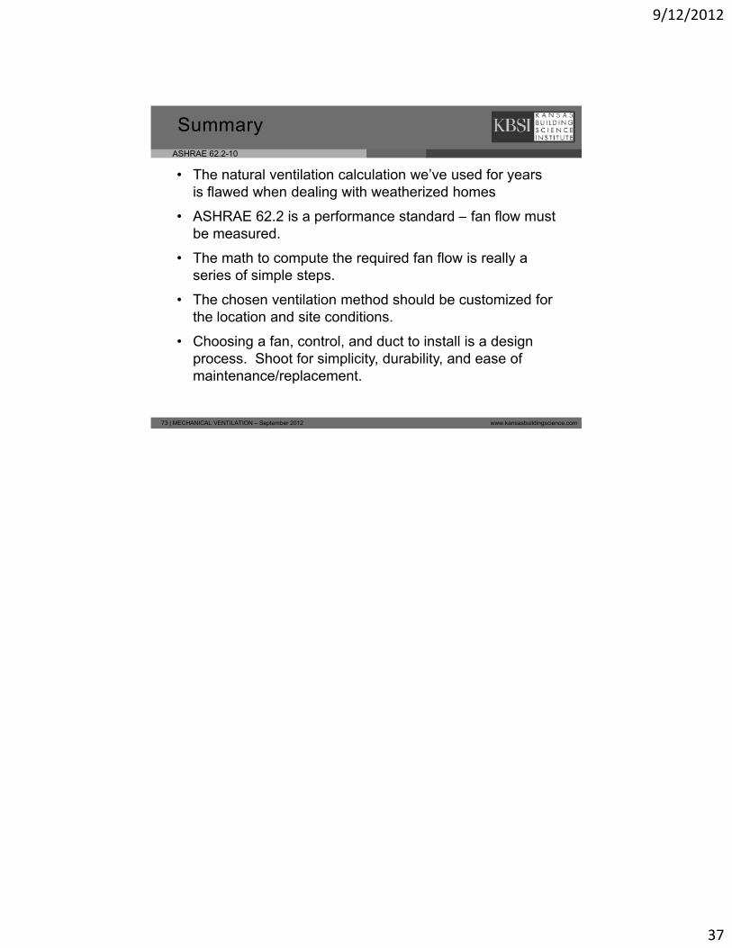
Work Flow - Inspector
71 | MECHANICAL VENTILATION – September 2012 www.kansasbuildingscience.com
ASHRAE 62.2-10
Setting the control
72 | MECHANICAL VENTILATION – September 2012 www.kansasbuildingscience.com
9/12/2012
37
ASHRAE 62.2-10
• The natural ventilation calculation we’ve used for years is flawed when dealing with weatherized homes
ASHRAE 62 2 is a performance standard fan flo m st
Summary
• ASHRAE 62.2 is a performance standard – fan flow must be measured.
• The math to compute the required fan flow is really a series of simple steps.
• The chosen ventilation method should be customized for the location and site conditions.
73 | MECHANICAL VENTILATION – September 2012 www.kansasbuildingscience.com
the location and site conditions.
• Choosing a fan, control, and duct to install is a design process. Shoot for simplicity, durability, and ease of maintenance/replacement.