Embed Size (px)
Citation preview
42 Cox Place, Glendenning NSW
Grosvenor Engineering Group Pty Ltd ABN 12 003 608 795 Y:\C59269 ‐ 42 Cox Place, Glendenning\C\M\20.02.19_for GPT as client\Mechanical Services Performance Brief_42 CoxD&C Contractor_19.02.2020.doc
DATE 19 February 2020
ISSUE D2 1 of 35 LL
Mechanical Services D &C Performance Brief
For the
Proposed Office / Warehouses Facilities 1 and 2 At
42 Cox Place, Glendenning NSW
For
The GPT Group Key Details
42 Cox Place, Glendenning NSW
Grosvenor Engineering Group Pty Ltd ABN 12 003 608 795 Y:\C59269 ‐ 42 Cox Place, Glendenning\C\M\20.02.19_for GPT as client\Mechanical Services Performance Brief_42 CoxD&C Contractor_19.02.2020.doc
DATE 19 February 2020
ISSUE D2 2 of 35 LL
Prepared for:
The GPT Group Level 51, MLC Centre, 19 Martin Place, Sydney NSW Tel: 61 2 8239 3555
Prepared by:
Grosvenor Engineering Group Pty Ltd 76 Heathcote Road Moore Bank NSW 2170 Tel: 02 9758 9555 Fax: 02 9758 9055
Building Involved: Proposed Warehouse 1 and 2, Office & Warehouse Facility at 42 Cox Place Glendenning NSW
42 Cox Place, Glendenning NSW
Grosvenor Engineering Group Pty Ltd ABN 12 003 608 795 Y:\C59269 ‐ 42 Cox Place, Glendenning\C\M\20.02.19_for GPT as client\Mechanical Services Performance Brief_42 CoxD&C Contractor_19.02.2020.doc
DATE 19 February 2020
ISSUE D2 3 of 35 LL
Grosvenor Engineering Group – QA System
SPECIFICATION No: C59269‐PB CLIENT: The GPT Group ENGINEER: Grosvenor Engineering Group Pty Ltd. PROJECT: Mechanical Ventilation and Air Conditioning systems for Proposed
Warehouse 1 and 2 ‐ Warehouse facility at 42 Cox Place, Glendenning NSW
Project Team Leader: Peter Souflias Mechanical Engineers: Saso Kuzmanovski, Ajith Vithanage
Date Revision Reason For Issue Authorised by
Verification By
10/02/2020 Draft ‐01 Issue for information SAK AJV
19/02/2020 Draft ‐02 Issue for D&C Tender SAK AJV
COPYRIGHT Copyright © 2002 by Grosvenor Engineering Group All rights reserved. No part of this document may be reproduced in any form, other than QUBE and their staff, by any means without the written permission of Grosvenor Engineering Group.
GROSVENOR ENGINEERING GROUP
ABN 12 003 608 795 76 Heathcote Road Moorebank NSW 2170 Telephone: (02) 9758 9555 Facsimile: (02) 9758 9055 Email: [email protected] Web: www.gegroup.com.au
Table of Contents
42 Cox Place, Glendenning NSW
Grosvenor Engineering Group Pty Ltd ABN 12 003 608 795 Y:\C59269 ‐ 42 Cox Place, Glendenning\C\M\20.02.19_for GPT as client\Mechanical Services Performance Brief_42 CoxD&C Contractor_19.02.2020.doc
DATE 19 February 2020
ISSUE D2 4 of 35 LL
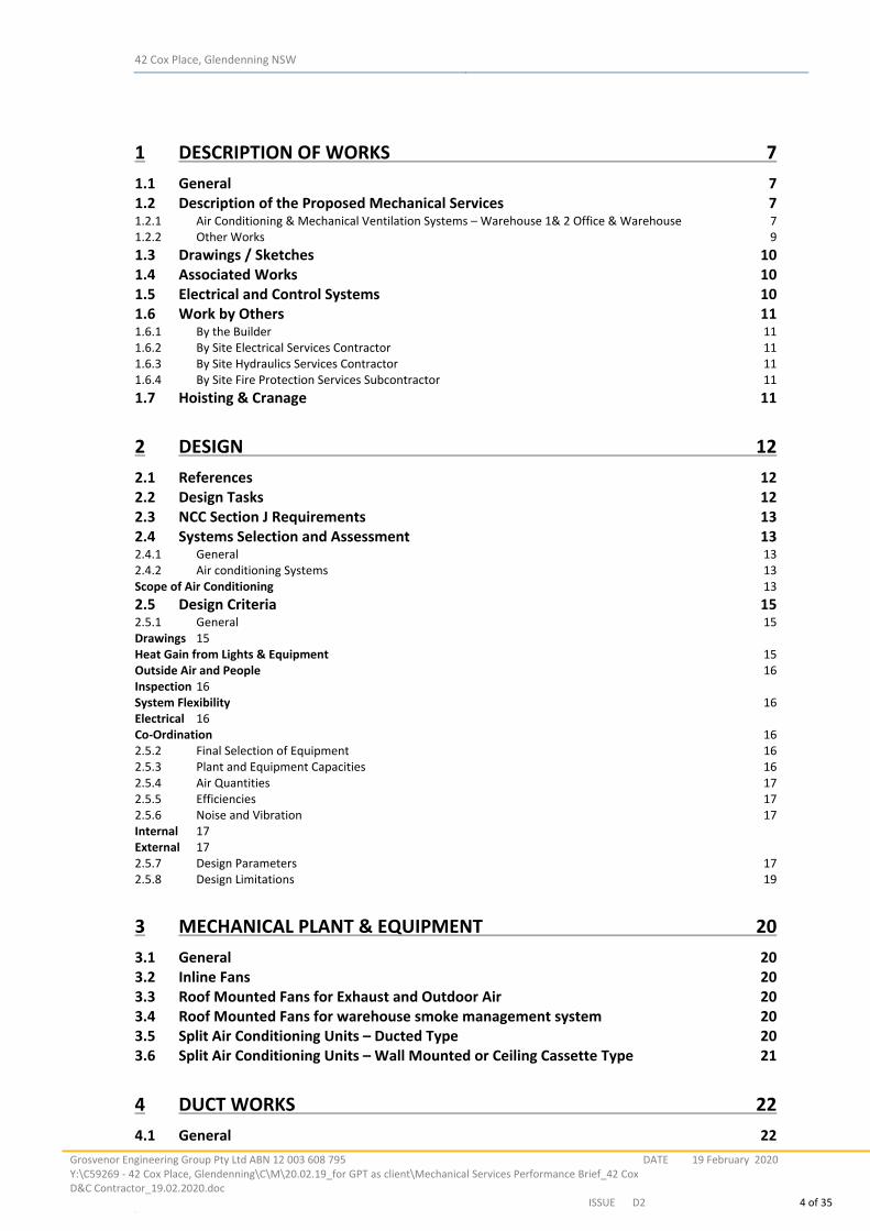
1 DESCRIPTION OF WORKS 7
1.1 General 7 1.2 Description of the Proposed Mechanical Services 7 1.2.1 Air Conditioning & Mechanical Ventilation Systems – Warehouse 1& 2 Office & Warehouse 7 1.2.2 Other Works 9 1.3 Drawings / Sketches 10 1.4 Associated Works 10 1.5 Electrical and Control Systems 10 1.6 Work by Others 11 1.6.1 By the Builder 11 1.6.2 By Site Electrical Services Contractor 11 1.6.3 By Site Hydraulics Services Contractor 11 1.6.4 By Site Fire Protection Services Subcontractor 11 1.7 Hoisting & Cranage 11
2 DESIGN 12
2.1 References 12 2.2 Design Tasks 12 2.3 NCC Section J Requirements 13 2.4 Systems Selection and Assessment 13 2.4.1 General 13 2.4.2 Air conditioning Systems 13 Scope of Air Conditioning 13 2.5 Design Criteria 15 2.5.1 General 15 Drawings 15 Heat Gain from Lights & Equipment 15 Outside Air and People 16 Inspection 16 System Flexibility 16 Electrical 16 Co‐Ordination 16 2.5.2 Final Selection of Equipment 16 2.5.3 Plant and Equipment Capacities 16 2.5.4 Air Quantities 17 2.5.5 Efficiencies 17 2.5.6 Noise and Vibration 17 Internal 17 External 17 2.5.7 Design Parameters 17 2.5.8 Design Limitations 19
3 MECHANICAL PLANT & EQUIPMENT 20
3.1 General 20 3.2 Inline Fans 20 3.3 Roof Mounted Fans for Exhaust and Outdoor Air 20 3.4 Roof Mounted Fans for warehouse smoke management system 20 3.5 Split Air Conditioning Units – Ducted Type 20 3.6 Split Air Conditioning Units – Wall Mounted or Ceiling Cassette Type 21
4 DUCT WORKS 22
4.1 General 22
42 Cox Place, Glendenning NSW
Grosvenor Engineering Group Pty Ltd ABN 12 003 608 795 Y:\C59269 ‐ 42 Cox Place, Glendenning\C\M\20.02.19_for GPT as client\Mechanical Services Performance Brief_42 CoxD&C Contractor_19.02.2020.doc
DATE 19 February 2020
ISSUE D2 5 of 35 LL
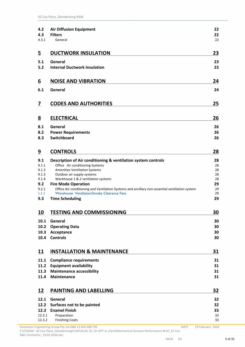
4.2 Air Diffusion Equipment 22 4.3 Filters 22 4.3.1 General 22
5 DUCTWORK INSULATION 23
5.1 General 23 5.2 Internal Ductwork Insulation 23
6 NOISE AND VIBRATION 24
6.1 General 24
7 CODES AND AUTHORITIES 25
8 ELECTRICAL 26
8.1 General 26 8.2 Power Requirements 26 8.3 Switchboard 26
9 CONTROLS 28
9.1 Description of Air conditioning & ventilation system controls 28 9.1.1 Office Air conditioning Systems 28 9.1.2 Amenities Ventilation Systems 28 9.1.3 Outdoor air supply systems 28 9.1.4 Warehouse 1 & 2 ventilation systems 28 9.2 Fire Mode Operation 29 9.2.1 Office Air‐conditioning and Ventilation Systems and ancillary non‐essential ventilation system 29 1.1.1 Warehouse Ventilation/Smoke Clearance Fans 29 9.3 Time Scheduling 29
10 TESTING AND COMMISSIONING 30
10.1 General 30 10.2 Operating Data 30 10.3 Acceptance 30 10.4 Controls 30
11 INSTALLATION & MAINTENANCE 31
11.1 Compliance requirements 31 11.2 Equipment availability 31 11.3 Maintenance accessibility 31 11.4 Maintenance 31
12 PAINTING AND LABELLING 32
12.1 General 32 12.2 Surfaces not to be painted 32 12.3 Enamel Finish 33 12.3.1 Preparation 33 12.3.2 Finishing Coats 33
42 Cox Place, Glendenning NSW
Grosvenor Engineering Group Pty Ltd ABN 12 003 608 795 Y:\C59269 ‐ 42 Cox Place, Glendenning\C\M\20.02.19_for GPT as client\Mechanical Services Performance Brief_42 CoxD&C Contractor_19.02.2020.doc
DATE 19 February 2020
ISSUE D2 6 of 35 LL
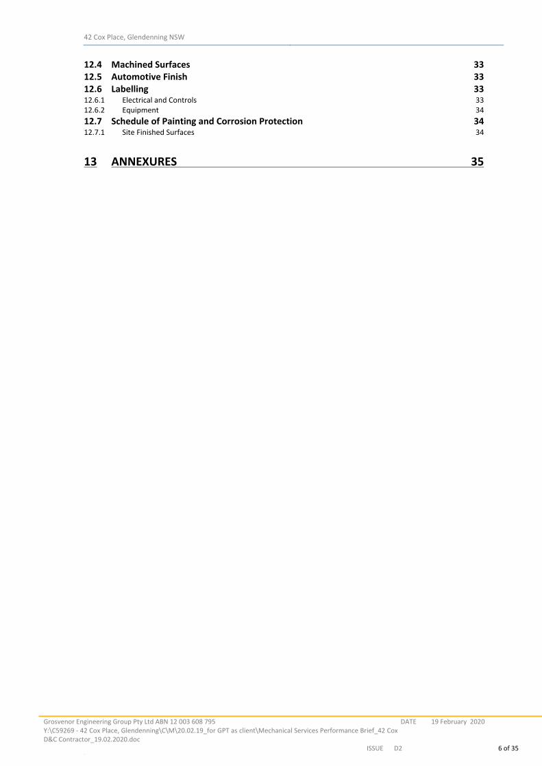
12.4 Machined Surfaces 33 12.5 Automotive Finish 33 12.6 Labelling 33 12.6.1 Electrical and Controls 33 12.6.2 Equipment 34 12.7 Schedule of Painting and Corrosion Protection 34 12.7.1 Site Finished Surfaces 34
13 ANNEXURES 35
42 Cox Place, Glendenning NSW
Grosvenor Engineering Group Pty Ltd ABN 12 003 608 795 Y:\C59269 ‐ 42 Cox Place, Glendenning\C\M\20.02.19_for GPT as client\Mechanical Services Performance Brief_42 CoxD&C Contractor_19.02.2020.doc
DATE 19 February 2020
ISSUE D2 7 of 35 LL
1 DESCRIPTION OF WORKS
1.1 General
This project site is located on 42 Cox Place Glendenning. The Mechanical Services section for this project comprises the design, supply, installation, testing, commissioning and maintenance of mechanical ventilation and associated works for the warehouse. The Mechanical Services shall comply with Project Performance Brief, Local Council requirements, the BCA (including Section J), the requirements of AS 1668 Ventilation Code Parts 1 and 2, Local Authorities, Electricity Authority, Water Authority, AS 3000, Fire Brigade requirements, Fire Engineer’s Report and other relevant regulations and standards. 1.2 Description of the Proposed Mechanical Services
The extent of work for this contract is specified as follows but not necessarily limited to that as stated below. The Mechanical Services Subcontractor shall provide all necessary items, even if unstated, required for the safe and correct operation of the systems provided. 1.2.1 Air Conditioning & Mechanical Ventilation Systems – Warehouse 1& 2 Office & Warehouse
Office Warehouse ‐ 1: The work shall include, but not limited, to the following:
Supply and installation of reveres cycle Inverter type single split air conditioning units to serve office area including:
o Fan coil units o Air distribution system o Condensing units o Controls o Power & control wiring, Mechanical switch board o Refrigeration piping
Supply and installation of toilet exhaust air systems, complete with an exhaust fan as shown on the drawings, rigid sheet metal ductwork, flexible ductwork, discharge louvre, exhaust air grilles and associated electrical/control works.
Supply and installation of outdoor air systems, complete a with fans as shown on the drawings, rigid sheet metal ductwork, flexible ductwork, intake grilles, filter arrangement and associated electrical/control works.
Supply and installation of all the refrigeration piping, pipe supports, piping thermal insulation and sheathing as recommended by the air conditioning equipment manufacturer.
Supply and installation of insulated condensate drains to the nearest tundishes provided by the hydraulic contactor. Condensate drain pumps shall be provided where sufficient gradient cannot be maintained.
Supply and installation of a mechanical services switchboard MSSB‐WH1 ‐1NE with associated switchgear and controls. The mechanical switchboard shall include a fire trip relay for the fire contractor to connect. The air conditioning system group controller for the building shall be located within the MSSB‐WH1 ‐1NE
42 Cox Place, Glendenning NSW
Grosvenor Engineering Group Pty Ltd ABN 12 003 608 795 Y:\C59269 ‐ 42 Cox Place, Glendenning\C\M\20.02.19_for GPT as client\Mechanical Services Performance Brief_42 CoxD&C Contractor_19.02.2020.doc
DATE 19 February 2020
ISSUE D2 8 of 35 LL
Office Warehouse ‐ 2: The work shall include, but not limited, to the following:
Supply and installation of reveres cycle Inverter type single split air conditioning units to serve office area including:
o Fan coil units o Air distribution system o Condensing units o Controls o Power & control wiring, Mechanical switch board o Refrigeration piping
Supply and installation of one toilet exhaust air systems, complete with an exhaust fan as shown on the drawings, rigid sheet metal ductwork, flexible ductwork, discharge louvre, exhaust air grilles and associated electrical/control works.
Supply and installation of one outdoor air systems, complete with fans as shown on the drawings, rigid sheet metal ductwork, flexible ductwork, intake grilles, filter arrangement and associated electrical/control works.
Supply and installation of outdoor air systems complete with roof mounted cowl as shown on the drawings, rigid sheet metal ductwork and flexible ductwork.
Supply and installation of all the refrigeration piping, pipe supports, piping thermal insulation and sheathing as recommended by the air conditioning equipment manufacturer.
Supply and installation of insulated condensate drains to the nearest tundishes provided by the hydraulic contactor. Condensate drain pumps shall be provided where sufficient gradient cannot be maintained.
Supply and installation of a mechanical services switchboard MSSB‐WH2‐1NE with associated switchgear and controls. The mechanical switchboard shall include a fire trip relay for the fire contractor to connect. The air conditioning system group controller for the building shall be located within the MSSB‐WH2 ‐1NE
Warehouse 1‐ Ventilation / Smoke Clearance Systems
The work shall include, but not limited, to the following: Supply and installation of eleven (11) off ducted smoke exhaust fans complete with
metal impellers, class H motors etc. in accordance with AS 1668.1‐2015.
Fire rated electrical and control wiring from MSSB‐WH1 ‐ 1E to the smoke clearance fans.
Supply and installation of all the necessary control interlocks for the fire contactor.
Supply and installation of a mechanical services essential switchboard MSSB‐WH1‐1E with associated switchgear and controls. The mechanical switchboard shall include a
42 Cox Place, Glendenning NSW
Grosvenor Engineering Group Pty Ltd ABN 12 003 608 795 Y:\C59269 ‐ 42 Cox Place, Glendenning\C\M\20.02.19_for GPT as client\Mechanical Services Performance Brief_42 CoxD&C Contractor_19.02.2020.doc
DATE 19 February 2020
ISSUE D2 9 of 35 LL
fire trip relay for the fire contractor to connect. The warehouse fan controls shall be located in the switch board.
Make‐up air arrangement shall be by others (builder). The make‐up air free area requirement as shown on the drawings.
Warehouse 2‐ Ventilation / Smoke Clearance Systems
The work shall include, but not limited, to the following: Supply and installation of seven (7) off ducted smoke exhaust fans complete with metal
impellers, class H motors etc. in accordance with AS 1668.1‐2015.
Fire rated electrical and control wiring from MSSB‐WH2 ‐ 1E to the smoke clearance fans.
Supply and installation of all the necessary control interlocks for the fire contactor.
Supply and installation of a mechanical services essential switchboard MSSB‐WH2‐1E with associated switchgear and controls. The mechanical switchboard shall include a fire trip relay for the fire contractor to connect. The warehouse fan controls shall be located in the switch board.
Make‐up air arrangement shall be by others (builder). The make‐up air free area requirement as shown on the drawings.
Warehouse 1&2 pump room Ventilation – TO BE CONFIRMED
The work shall include, but not limited, to the following: The pump room shall be ventilated to the requirements of fire services contractor. The mechanical services contractor shall coordinate with fire services contractor for heat emission and required temperature to be maintained. Accordingly to be provided with a suitable ventilation system.
1.2.2 Other Works
The work shall include, but not limited, to the following:
Noise attenuators to accommodate the required noise levels (if required)
Anti‐vibration mounts.
Supply and installation of external louvers.
Supply of door grilles (for installation By Builder)
Provision of sealing of all pipes, ducts and cable penetrations through acoustic and standard walls, floors and ceilings.
Air balance.
Testing and commissioning.
Certification.
Provision of O & M manuals in hard and soft copy format (PDF)
Provision of ‘as installed’ drawings in hard and soft format (PDF & AutoCAD).
42 Cox Place, Glendenning NSW
Grosvenor Engineering Group Pty Ltd ABN 12 003 608 795 Y:\C59269 ‐ 42 Cox Place, Glendenning\C\M\20.02.19_for GPT as client\Mechanical Services Performance Brief_42 CoxD&C Contractor_19.02.2020.doc
DATE 19 February 2020
ISSUE D2 10 of 35 LL
Supply and installation of fire rated material around pipes, which pass through fire barriers.
Supply and installation of escutcheons and sleeves for all pipe and electrical penetrations of barriers to ensure neat appearance.
Provision for all cranage, hoisting, transport and handling for all new and redundant equipment and materials, and manoeuvre all equipment into their final positions.
Authorities’ permits and associated costs.
Removal from site, and proper disposal of all rubbish, surplus and redundant materials.
Testing and commissioning of the systems described above in accordance with Section “Testing and Commissioning”.
Painting of all plant and equipment in accordance with Section “Painting and Labelling”.
Identification of all plant and equipment with labels and numbering consistent with these documents and in accordance with Section “Painting and Labelling”.
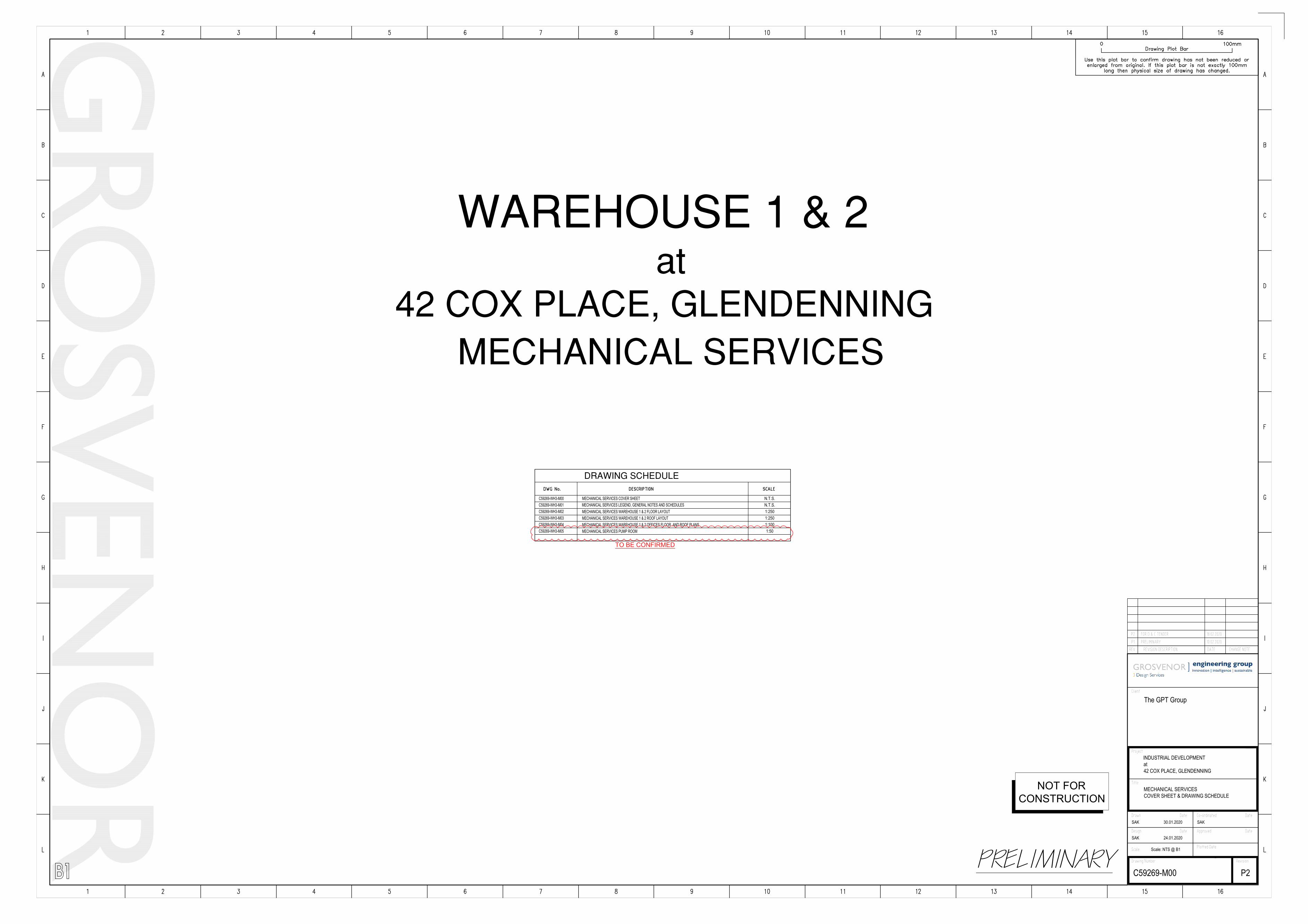
1.3 Drawings / Sketches
The following Mechanical Services Design Intent Drawings accompanying this Performance Brief shall be read in conjunction with this Brief.
C59269‐M00 MECHANICAL SERVICES COVER SHEET
C59269‐M01 MECHANICAL SERVICES LEGEND, GENERAL NOTES AND SCHEDULES
C59269‐M02 MECHANICAL SERVICES WAREHOUSE 1 & 2 FLOOR LAYOUT
C59269‐M03 MECHANICAL SERVICES WAREHOUSE 1 & 2 ROOF LAYOUT
C59269‐M04 MECHANICAL SERVICES WAREHOUSE 1 & 2 OFFICES FLOOR AND ROOF PLANS
C59269‐M05 MECHANICAL SERVICES PUMP ROOM
1.4 Associated Works
The work shall include, but not limited, to the following:
Testing, Balancing and Commissioning of installed systems.
Provide 12 months warranty on parts.
Provide 12 months guarantee on workmanship.
Provide Operating and Maintenance Manuals (prior to Practical Completion).
Provide as installed drawings (prior to Practical Completion).
Certification of the total installation (prior to Practical Completion).
Provide all certificates required by authorities (prior to Practical Completion).
Lifting and positioning of Equipment.
1.5 Electrical and Control Systems
The works shall include, but not be limited to, the following:
Supply and installation of all electrical power and control wiring from the mechanical switchboards to the mechanical equipment for the complete and correct operation of the mechanical services.
42 Cox Place, Glendenning NSW
Grosvenor Engineering Group Pty Ltd ABN 12 003 608 795 Y:\C59269 ‐ 42 Cox Place, Glendenning\C\M\20.02.19_for GPT as client\Mechanical Services Performance Brief_42 CoxD&C Contractor_19.02.2020.doc
DATE 19 February 2020
ISSUE D2 11 of 35 LL
1.6 Work by Others
1.6.1 By the Builder
Forming all openings and penetrations in walls and ceiling for the passage of ductwork and pipework. Provided information and drawing set out provided to the Builder by the Mechanical Services Contractor in sufficient time for the works to be carried out in accordance with the Builder’s program.
Installation of door grilles supplied by the Mechanical Services Contractor.
Making good the penetrations.
Undercutting of doors (must be clearly defined on shop drawings).
Temporary power during installation.
Supply and installation of weather proof louvres.
Supply and installation anchor points for the installation and servicing of the equipment.
Supply and installation of screens around mechanical equipment.
1.6.2 By Site Electrical Services Contractor
Electrical sub mains (essential and non‐essential power) to mechanical switchboards or panels to positions nominated by the Mechanical Services Contractor.
1.6.3 By Site Hydraulics Services Contractor
Tundishes for waste from mechanical equipment. (Mechanical contractor to allow running condensate lines to tundishes locations shown on hydraulic drawings).
1.6.4 By Site Fire Protection Services Subcontractor
Provision of fire trip signals to all Mechanical Services Switchboards as required.
1.7 Hoisting & Cranage The mechanical services subcontractor shall provide hoisting and cranage for all equipment, fittings
and tools required.
42 Cox Place, Glendenning NSW
Grosvenor Engineering Group Pty Ltd ABN 12 003 608 795 Y:\C59269 ‐ 42 Cox Place, Glendenning\C\M\20.02.19_for GPT as client\Mechanical Services Performance Brief_42 CoxD&C Contractor_19.02.2020.doc
DATE 19 February 2020
ISSUE D2 12 of 35 LL
2 DESIGN
2.1 References
The design and documentation is to be referenced to the following but not limited to:
Project Architectural Drawings
Project section JV3 report
The Building Code of Australia
State Statutory Regulations
Relevant Australian Standards including but not limited to AS 1668.1, AS 1668.2, AS 3666, AS 4254, AS 1432, AS 3000, AS 3008, AS1677, AS2107 , AS3959 etc.
The requirements of the local council and the local supply authorities.
Project fire engineer’s report
The requirements of the relevant state WorkCover Authority
2.2 Design Tasks
The following tasks in the design development stages are to form part of the contract work but not limited to:
Carry out full calculations of cooling and heating loads for all air conditioned areas based on Design Criteria provided, architectural drawings and reference material.
Carry out full calculations of the ventilation requirements based on Design Criteria provided architectural drawings and reference material.
Size all ductwork and pipework in accordance with specified parameters.
Provide design and development detail of ductwork and pipework layout to allow full co‐ordination with the building structure and other engineering services where required in keeping with the concept and intent of the project.
Provide detail design and development of plant/ ceiling voids requirements with all equipment in place to allow full utilisation of space and ease of access for maintenance.
Size and locate all room air outlets and inlets and co‐ordinate with the lighting layout and other services to provide an efficient draft free distribution in the rooms.
Size, locate and interconnect all plant, as required.
Incorporate individual return air grilles and ductwork to areas/rooms where hard plaster ceilings are used and for acoustic purpose where required.
42 Cox Place, Glendenning NSW
Grosvenor Engineering Group Pty Ltd ABN 12 003 608 795 Y:\C59269 ‐ 42 Cox Place, Glendenning\C\M\20.02.19_for GPT as client\Mechanical Services Performance Brief_42 CoxD&C Contractor_19.02.2020.doc
DATE 19 February 2020
ISSUE D2 13 of 35 LL
2.3 NCC Section J Requirements
The Mechanical Services Contractor shall ensure that the final installation complies with the requirements of the Section J (Energy Efficiency) in the NCC. The requirements of NCC 2013 Section J include (but not limited to) the following;
Exhaust systems serving air‐conditioned areas to have self‐closing back draft dampers.
All air conditioning units and ventilation systems to shut down when building is not occupied and time clocks required on all air conditioning units above 10 kW.
Air conditioning units above 1000 L/s in airflow to have shaft power not exceeding 12 W/m2 up to 500 m2 unless the units comply with efficiencies specified /tabulated in Section J.
Efficiency of air conditioning equipment to comply with the co‐efficient of performance nominated in Section J.
2.4 Systems Selection and Assessment
2.4.1 General
The heating and cooling plant and air conditioning air handling systems shall be selected to have the lowest life cycle cost over the 15 year period specified. Tenderers must demonstrate this through tender schedules and supplementary information. High priority in assessing tenders will be given to the energy efficiency and low life cycle cost.
Systems must be selected from the following or from alternative systems that can be proved by the Contractor to have a lower life cycle cost
In general preference will be given to systems which:‐
Minimise energy use
Permit zones to be shut down when unoccupied.
Minimise maintenance costs.
Maximise reliability and availability of plant.
Systems should avoid/minimise the need for servicing within the typical rooms
2.4.2 Air conditioning Systems
Scope of Air Conditioning
The mechanical services works shall include the design, supply and installation of air conditioning system, power supply, controls, ductwork, drainage, supports, flushing, ancillary equipment etc. to form a complete system. The equipment and systems shall be designed to meet the design and performance requirements as indicated within this specification.
Air conditioning shall be provided to the following areas ( shall be as per project design brief ) :
- Offices Warehouse 1 & 2
Requirement of the AC system:
Air conditioning systems shall be of the air‐cooled reverse cycle inverter type split systems
42 Cox Place, Glendenning NSW
Grosvenor Engineering Group Pty Ltd ABN 12 003 608 795 Y:\C59269 ‐ 42 Cox Place, Glendenning\C\M\20.02.19_for GPT as client\Mechanical Services Performance Brief_42 CoxD&C Contractor_19.02.2020.doc
DATE 19 February 2020
ISSUE D2 14 of 35 LL
ducted fan coil units. As a minimum systems shall be designed and installed in accordance with
the following:
o Mechanical plant must be screened.
o To be designed to Tenant’s office area layout.
o Supply and install an air conditioning system for each thermal zone. The
thermal zone shall include perimeter and centre zones, Lunch Rooms,
Training Rooms, Conference and Meeting Rooms (over 15m²). Each system
shall be fitted with integrated automatic controls.
o Temperature sensors to be provided within each zone with controllers
associated with each sensor to be installed in a lockable switchboard. If the
warehouse has temperature control areas, the office AC is to be connected to
the BMS.
o Set point Temperature 22.5 degrees C +/‐ 1.5 degrees C – Range 21 to 24 degrees C
o Outside air rates in accordance with A.S. 1668.2 ‐ 2012 “Mechanical Ventilation
for Acceptable Indoor Air Quality”.
o Air conditioning to be designed to applicable National Standards.
o Supply air quantity to be based on calculated heat loads but not be less than 5 l/s/m².
o Infiltration allowance to be 0.5 air changes per hour in entry areas.
o Air on condensers shall be 5˚C above design if subject to roof temperature.
o Occupancy based on 1 person per 10 m².
o Thermal zoning shall not exceed 120 m² for centre zones and 80 m² for perimeter zones.
o A/C unit selection not to exceed 22k W in capacity for a thermal zone.
o A time clock will be provided with provision for after‐hours override switches
fitted on each level of office. Ability to manage timers on the different zones
based on after hours occupancy.
o Noise levels from mechanical installations to meet ‘Recommended Levels’ of
AS2107. Office/Production: NR35; Amenities: NR45. Noise Level test and
report to be provided within 30 days of Practical Completion
o Filtration on air conditioning systems to be minimum Grade F5 to AS1324.
o Lighting Loading to meet NCC Section J requirements – not to exceed 10 W/m².
o Equipment loading to be 15W/m² for typical office space. For production areas,
to suit installed equipment.
o Mechanical Ventilation systems for amenities and other special use areas to be
in accordance with the requirements of AS 1668 Part 2 2012
o Air diffusion equipment, swirl diffusers to be utilized in all air conditioned
spaces as terminal devices. AC units to have their own control (with limited
access) in enclosed rooms in the office, including but not limited to, meeting
rooms, Conference Room and Training Rooms.
o IT room – two standard alone wall mounted air conditioning units with
combined capacity to suit area heat load requirements from proposed
equipment.
o The AC systems shall be controlled by a proprietary group controller. The
controls shall be located within the respective mechanical services switch
board.
42 Cox Place, Glendenning NSW
Grosvenor Engineering Group Pty Ltd ABN 12 003 608 795 Y:\C59269 ‐ 42 Cox Place, Glendenning\C\M\20.02.19_for GPT as client\Mechanical Services Performance Brief_42 CoxD&C Contractor_19.02.2020.doc
DATE 19 February 2020
ISSUE D2 15 of 35 LL
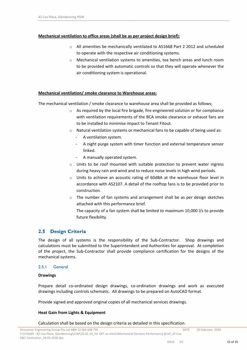
Mechanical ventilation to office areas (shall be as per project design brief):
o All amenities be mechanically ventilated to AS1668 Part 2 2012 and scheduled
to operate with the respective air conditioning systems.
o Mechanical ventilation systems to amenities, tea bench areas and lunch room
to be provided with automatic controls so that they will operate whenever the
air conditioning system is operational.
Mechanical ventilation/ smoke clearance to Warehouse areas:
The mechanical ventilation / smoke clearance to warehouse area shall be provided as follows;
o As required by the local fire brigade, fire engineered solution or for compliance
with ventilation requirements of the BCA smoke clearance or exhaust fans are
to be installed to minimise impact to Tenant Fitout.
o Natural ventilation systems or mechanical fans to be capable of being used as:
- A ventilation system.
- A night purge system with timer function and external temperature sensor
linked.
- A manually operated system.
o Units to be roof mounted with suitable protection to prevent water ingress
during heavy rain and wind and to reduce noise levels in high wind periods.
o Units to achieve an acoustic rating of 60dBA at the warehouse floor level in
accordance with AS2107. A detail of the rooftop fans is to be provided prior to
construction.
o The number of fan systems and arrangement shall be as per design sketches
attached with this performance brief.
The capacity of a fan system shall be limited to maximum 10,000 l/s to provide
future flexibility.
2.5 Design Criteria
The design of all systems is the responsibility of the Sub‐Contractor. Shop drawings and calculations must be submitted to the Superintendent and Authorities for approval. At completion of the project, the Sub‐Contractor shall provide compliance certification for the designs of the mechanical systems.
2.5.1 General
Drawings
Prepare detail co‐ordinated design drawings, co‐ordination drawings and work as executed drawings including controls schematic. All drawings to be prepared on AutoCAD format.
Provide signed and approved original copies of all mechanical services drawings.
Heat Gain from Lights & Equipment
Calculation shall be based on the design criteria as detailed in this specification.
42 Cox Place, Glendenning NSW
Grosvenor Engineering Group Pty Ltd ABN 12 003 608 795 Y:\C59269 ‐ 42 Cox Place, Glendenning\C\M\20.02.19_for GPT as client\Mechanical Services Performance Brief_42 CoxD&C Contractor_19.02.2020.doc
DATE 19 February 2020
ISSUE D2 16 of 35 LL
Outside Air and People
Calculation shall be based on the design criteria as detailed in this specification.
Inspection
Give sufficient notice (minimum 2 days) so that the superintendent may attend tests and so that inspection may be made of concealed services prior to covering. In cases where no such notice is given the test shall be redone in the presence of the superintendent at no cost.
System Flexibility
The design of Mechanical Services must incorporate the following features to facilitate future modifications. The Contractor may propose alternative means of providing flexibility during the Design Development phase provided the result gives an equivalent degree of flexibility for future modifications.
Electrical
Provision of 30% minimum extra space & spare capacity shall be allowed.
Co‐Ordination
Requirement: Co‐ordinate all mechanical services with other trades.
Pressure Drops
Fans shall be generally located on the dustcover above offices with adequate allowance for maintenance access.
Exhaust air shall discharge sideways via weatherproof exhaust air louvre.
Outside air shall be introduced above roof via roof mounted roof cowls or sideways via weatherproof outside air louvre. Roof cowls shall be selected at a maximum 20Pa of pressure drop.
2.5.2 Final Selection of Equipment
The Contractor shall undertake a technical evaluation of the system components based on actual characteristics of the selected equipment, and fully engineered the Air Conditioning Systems. Special care shall be taken to ensure that the system components are correctly matched to operate within the specified system parameters and be capable of meeting the specified performance requirements. If requested, prior to ordering major equipment, the Contractor shall submit to the Superintendent for perusal, a copy of his Engineering calculations and the design parameters of each item of equipment.
Subsequent to approval of Workshop Drawings, the Contractor shall check static pressure calculations for ducting and piping systems to ensure that associated equipment has been selected for the required duty to suit the installation.
2.5.3 Plant and Equipment Capacities
All plant and equipment installed under this Specification shall meet the performance characteristics as outlined within this Specification as applicable.
42 Cox Place, Glendenning NSW
Grosvenor Engineering Group Pty Ltd ABN 12 003 608 795 Y:\C59269 ‐ 42 Cox Place, Glendenning\C\M\20.02.19_for GPT as client\Mechanical Services Performance Brief_42 CoxD&C Contractor_19.02.2020.doc
DATE 19 February 2020
ISSUE D2 17 of 35 LL
2.5.4 Air Quantities
Airflow quantities shall be suitable to satisfy the design criteria as listed within this Specification. Check air quantities and compatibility of the offered equipment whether specified or as an alternative.
2.5.5 Efficiencies
The various efficiencies of equipment and/or systems shall be set out and guaranteed. All work and instruments necessary to prove the "guaranteed efficiency" by establishing the "measured efficiency" from appropriate tests shall be made available.
2.5.6 Noise and Vibration
Use equipment that operates within the required noise and vibration limits. Prevent the transmission of vibration from rotating or reciprocating equipment to other building elements using static and dynamic balancing, and anti‐vibration mounting supports and hangers.
Internal
Noise levels in the occupied or specified space shall be maintained at or below the noise rating number nominated as "Satisfactory" under the "Recommended Design Sound Level" in AS 2107 under all conditions of operation of plant, air distribution and volume and temperature fluctuation.
External
Noise emission to be in compliance with code requirements
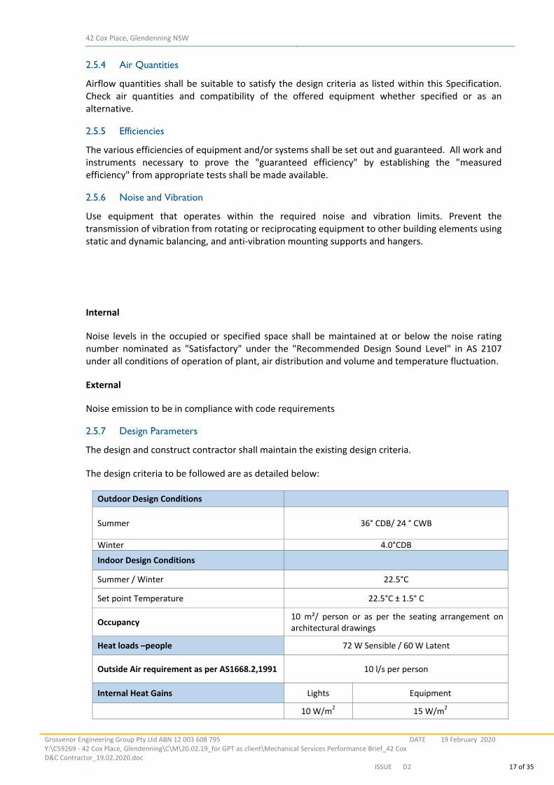
2.5.7 Design Parameters
The design and construct contractor shall maintain the existing design criteria.
The design criteria to be followed are as detailed below:
Outdoor Design Conditions
Summer 36° CDB/ 24 ° CWB
Winter 4.0°CDB
Indoor Design Conditions
Summer / Winter 22.5°C
Set point Temperature 22.5°C ± 1.5° C
Occupancy 10 m²/ person or as per the seating arrangement on architectural drawings
Heat loads –people 72 W Sensible / 60 W Latent
Outside Air requirement as per AS1668.2,1991 10 l/s per person
Internal Heat Gains Lights Equipment
10 W/m2 15 W/m2
42 Cox Place, Glendenning NSW
Grosvenor Engineering Group Pty Ltd ABN 12 003 608 795 Y:\C59269 ‐ 42 Cox Place, Glendenning\C\M\20.02.19_for GPT as client\Mechanical Services Performance Brief_42 CoxD&C Contractor_19.02.2020.doc
DATE 19 February 2020
ISSUE D2 18 of 35 LL
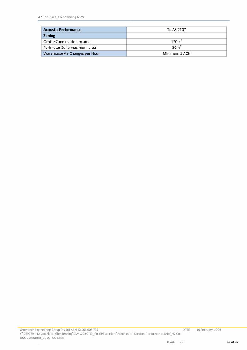
Acoustic Performance To AS 2107
Zoning
Centre Zone maximum area 120m2
Perimeter Zone maximum area 80m2
Warehouse Air Changes per Hour Minimum 1 ACH
42 Cox Place, Glendenning NSW
Grosvenor Engineering Group Pty Ltd ABN 12 003 608 795 Y:\C59269 ‐ 42 Cox Place, Glendenning\C\M\20.02.19_for GPT as client\Mechanical Services Performance Brief_42 CoxD&C Contractor_19.02.2020.doc
DATE 19 February 2020
ISSUE D2 19 of 35 LL
2.5.8 Design Limitations
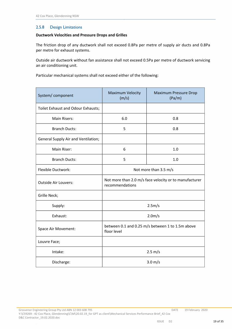
Ductwork Velocities and Pressure Drops and Grilles
The friction drop of any ductwork shall not exceed 0.8Pa per metre of supply air ducts and 0.8Pa per metre for exhaust systems.
Outside air ductwork without fan assistance shall not exceed 0.5Pa per metre of ductwork servicing an air conditioning unit.
Particular mechanical systems shall not exceed either of the following:
System/ component Maximum Velocity
(m/s) Maximum Pressure Drop
(Pa/m)
Toilet Exhaust and Odour Exhausts;
Main Risers: 6.0 0.8
Branch Ducts: 5 0.8
General Supply Air and Ventilation;
Main Riser: 6 1.0
Branch Ducts: 5 1.0
Flexible Ductwork: Not more than 3.5 m/s
Outside Air Louvers: Not more than 2.0 m/s face velocity or to manufacturer recommendations
Grille Neck;
Supply: 2.5m/s
Exhaust: 2.0m/s
Space Air Movement: between 0.1 and 0.25 m/s between 1 to 1.5m above floor level
Louvre Face;
Intake: 2.5 m/s
Discharge: 3.0 m/s
42 Cox Place, Glendenning NSW
Grosvenor Engineering Group Pty Ltd ABN 12 003 608 795 Y:\C59269 ‐ 42 Cox Place, Glendenning\C\M\20.02.19_for GPT as client\Mechanical Services Performance Brief_42 CoxD&C Contractor_19.02.2020.doc
DATE 19 February 2020
ISSUE D2 20 of 35 LL
3 MECHANICAL PLANT & EQUIPMENT
3.1 General
The mechanical plant and equipment, under this contract shall include, but not necessarily be limited to the following items.
3.2 Inline Fans
In‐line‐ fans shall have non‐overloading characteristics and be of the direct driven type suitable for 3 phase 400V 50Hz or 230/1/50Hz power supplies. Fans shall be Fans Direct, Fantech or approved equal. Fan motors shall be MEPS 2 (compliant to Section J of the BCA) standard for single and three phases, 2, 4 or 6 pole and incorporate built in overload protection. 3.3 Roof Mounted Fans for Exhaust and Outdoor Air
Propeller fans shall have non‐overloading characteristics and be of the direct driven type suitable for 230/1/50Hz & 400V/3/50 power supplies. Fans shall be Fans Direct or approved equal. Fan motors shall be MEPS 2 (compliant to Section J of the BCA) standard for single and three Phases, 2, 4 or 6 pole and incorporate built in overload protection. 3.4 Roof Mounted Fans for warehouse smoke management system
The axial impellers shall be adjustable pitch and manufactured in aluminium. Construction of the
impellers shall be to suit the elevated temperatures with blades pinned as necessary.
Motors shall be selected to suit the elevated temperatures (Class H) and suitable for 3 phase /415
Volts/50 Hz.
All fans shall be tested to meet the air‐flow, temperature, sound level and structural requirements
of AS 1668 Part 1, 2015, and AS 4429, 1999.
Note: Each fan assembly shall be provided with back draft dampers.
3.5 Split Air Conditioning Units – Ducted Type
Split type air conditioners shall be of the inverter, reverse cycle type manufactured by Mitsubishi Electric Australia or approved equivalent. All units shall have the provision of reversing the refrigeration effect unless specified otherwise. Outdoor systems shall be capable of operating at temperatures of 45°C. Refrigerant type shall be R410A. The contractor is also responsible to incorporate any recommendations from manufacturers considered for this project for refrigerant piping runs to minimise capacity loss. There commendations may include upsized suction lines, suction accumulators, oil traps in vertical runs of pipework etc. The cooling and heating a capacity of the a/c unit shall be tested under the AREMA testing program and perform satisfactorily to the AREMA UEPS (7/84) standard for the external conditions. The A/C unit shall also comply with the requirements of MEPS 2 and Section J BCA. The contractor shall ensure that all the piping, electrical and control wiring shall be as per the Manufacturer’s recommendation and as a result of the use of the dedicated design software. The evaporator fan shall be capable of performing the required duty while operating under the nominated criteria as shown on drawings and schedules. Outdoor systems shall be capable of operating at temperatures of 45°C. The system resistance as shown is an assessment for tendering purposes only. The Mechanical Services Contractor shall take into account the actual system resistance and select the fan motor size accordingly.
42 Cox Place, Glendenning NSW
Grosvenor Engineering Group Pty Ltd ABN 12 003 608 795 Y:\C59269 ‐ 42 Cox Place, Glendenning\C\M\20.02.19_for GPT as client\Mechanical Services Performance Brief_42 CoxD&C Contractor_19.02.2020.doc
DATE 19 February 2020
ISSUE D2 21 of 35 LL
The ducted indoor units shall be provided with additional condensate drain tray and to be connected to the condensate drain line. When selecting the equipment maximum allowable piping length shall strictly to be taken into consideration. 3.6 Split Air Conditioning Units – Wall Mounted or Ceiling Cassette Type
Split type air conditioners shall be of the inverter, reverse cycle type manufactured by Mitsubishi Electric Australia or approved equivalent. All units shall have the provision of reversing the refrigeration effect unless specified otherwise. Outdoor systems shall be capable of operating at temperatures of 45°C. Refrigerant type shall be ODP of zero R410A. The cooling and heating a capacity of the a/c unit shall be tested under the AREMA testing program and perform satisfactorily to the AREMA UEPS (7/84) standard for the external conditions. The units shall also comply with the requirements of MEPS 2 and Section J BCA.I indoor units shall have fans that under high‐speed operation do not exceed sound pressure level of 44 dba. The unit shall be provided with automatic controls and infrared remote controller. Units shall be installed with a minimum 7 day timer function. The contractor is also responsible to incorporate any recommendations from manufacturers considered for this project for refrigerant piping runs to minimise capacity loss. The commendations may include upsized suction lines, suction accumulators, oil traps in vertical runs of pipe work etc. When selecting the equipment maximum allowable piping length shall strictly to be taken into consideration. Installed and comply with the requirements of AS 1668 Part 1 and AS 3000.
42 Cox Place, Glendenning NSW
Grosvenor Engineering Group Pty Ltd ABN 12 003 608 795 Y:\C59269 ‐ 42 Cox Place, Glendenning\C\M\20.02.19_for GPT as client\Mechanical Services Performance Brief_42 CoxD&C Contractor_19.02.2020.doc
DATE 19 February 2020
ISSUE D2 22 of 35 LL
4 DUCT WORKS
4.1 General
All ductwork shall be installed in a workman‐like manner to the general arrangement as shown on the drawings. Ductwork shall be installed complete with all fittings and components as necessary for operation and balancing and shall be arranged to provide full access to duct elements requiring inspection, entry, maintenance and repairs, such as dampers, fans and other items. Ductwork sections and associated fittings shall not obstruct access to any other equipment.
Ductwork to comply with the requirements of AS 4254 to be airtight ‐ ductwork must be sealed and pressure tested to the requirements of the standard.
4.2 Air Diffusion Equipment
All air outlets shall be selected to provide satisfactory air movement within the space without generation of noise in excess of design criteria requirements. Each air outlet shall be fitted with facilities to allow for individual air balancing. Approval shall be obtained for each type of outlet proposed prior to ordering. Supply air outlets are to be of the swirl type diffusers without OBDs. Return and exhaust air grilles shall be of the 12mm x 12mm egg crate formed from blades that are 12mm deep. Exhaust air grilles shall be complete with opposed blade dampers. The grilles shall have a minimum of 85% free area and shall have removable cores. The frame and core shall be of all aluminium construction and shall be supplied in a baked enamel finish to colour to be advised. 4.3 Filters
4.3.1 General
Air filters shall be as manufactured and supplied by Vilair‐ AAF Pty. Ltd Camfil Farr, or approved equal, 50 mm disposable dry media fabric. Filters for non ‐ ducted type units shall be of the type as supplied by the manufacturer.
At the completion of acceptance of testing of all air handling units and before handing any air handling systems over to the Proprietor, filter media shall be replaced with clean new filter media.
The filter media shall contain oil or gel additives and the filters face velocity shall be selected to suit the catalogue ratings for each particular filter.
Filters shall comply with AS1324.1 – 2001 and to AS1668.2. A National Association of Testing Authorities Australia (NATA) certified test report shall be made available upon request for each type of filter offered. ASHRAE 52 and EN779 testing is acceptable.
Minimum performance Rating shall be F5 as per AS1324.1 – 2001 and to AS1668.2 Minimum performance filter shall be: Minimum Efficiency 20% Average Efficiency 25%
Average Arrestance 90%
42 Cox Place, Glendenning NSW
Grosvenor Engineering Group Pty Ltd ABN 12 003 608 795 Y:\C59269 ‐ 42 Cox Place, Glendenning\C\M\20.02.19_for GPT as client\Mechanical Services Performance Brief_42 CoxD&C Contractor_19.02.2020.doc
DATE 19 February 2020
ISSUE D2 23 of 35 LL
5 DUCTWORK INSULATION
5.1 General
All insulation materials (including facings and adhesives) used in the installation shall conform to AS 1668 Part 1 and meet the requirements of the relevant authorities where forming part of duct systems or installed in return air plenums or ceiling return air paths. Duct internal insulation shall be designed for all systems where excessive noise transmission to conditioned spaces is of concern.
This section of the specification sets out the requirements for thermal an acoustic insulation associated with ductwork, piping and equipment to be installed as part of this Contract Materials for thermal insulation and sound absorption treatment shall have the following indexes when tested in accordance with AS 1530 Part III.
i. A spread of flame index not greater than 0. ii. A smoke developed index number not greater than 3.
The insulation materials shall be non‐hydroscopic, resistant to bacteria, algae, vermin and growth of moulds or fungi.
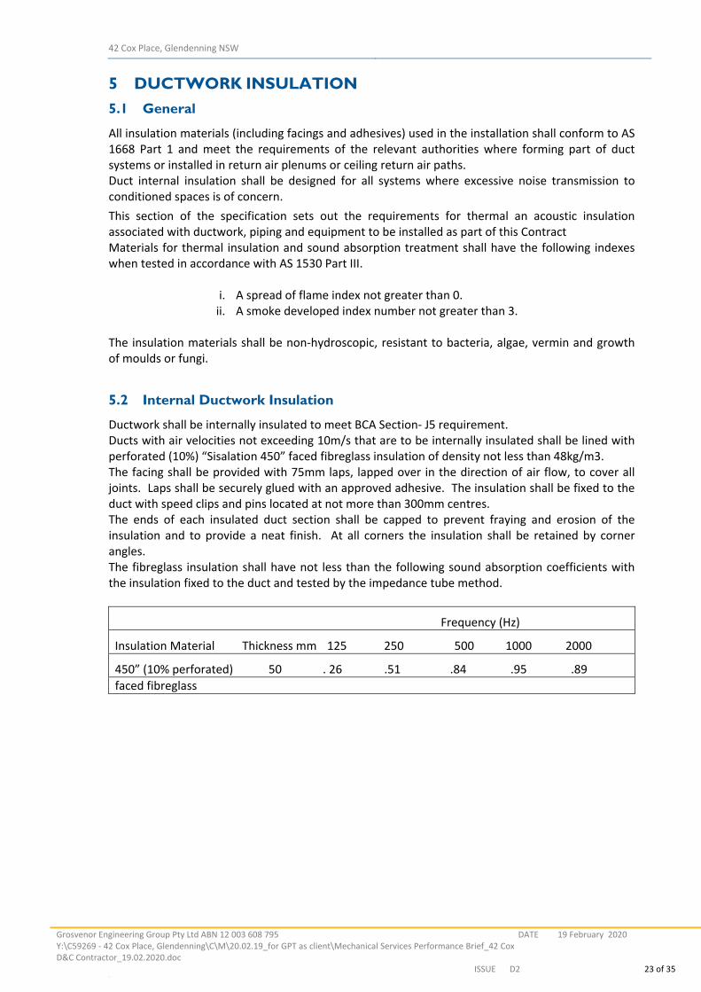
5.2 Internal Ductwork Insulation
Ductwork shall be internally insulated to meet BCA Section‐ J5 requirement. Ducts with air velocities not exceeding 10m/s that are to be internally insulated shall be lined with perforated (10%) “Sisalation 450” faced fibreglass insulation of density not less than 48kg/m3. The facing shall be provided with 75mm laps, lapped over in the direction of air flow, to cover all joints. Laps shall be securely glued with an approved adhesive. The insulation shall be fixed to the duct with speed clips and pins located at not more than 300mm centres. The ends of each insulated duct section shall be capped to prevent fraying and erosion of the insulation and to provide a neat finish. At all corners the insulation shall be retained by corner angles. The fibreglass insulation shall have not less than the following sound absorption coefficients with the insulation fixed to the duct and tested by the impedance tube method.
Frequency (Hz)
Insulation Material Thickness mm 125 250 500 1000 2000
450” (10% perforated) 50 . 26 .51 .84 .95 .89
faced fibreglass
42 Cox Place, Glendenning NSW
Grosvenor Engineering Group Pty Ltd ABN 12 003 608 795 Y:\C59269 ‐ 42 Cox Place, Glendenning\C\M\20.02.19_for GPT as client\Mechanical Services Performance Brief_42 CoxD&C Contractor_19.02.2020.doc
DATE 19 February 2020
ISSUE D2 24 of 35 LL
6 NOISE AND VIBRATION
6.1 General
All systems, equipment, pipework and ductwork shall be selected, manufactured and installed for quiet and vibration free operation in accordance with the requirements of this Specification and within the noise and vibration criteria as specified for individual items of equipment, acoustic linings and vibration isolation. Mechanical plant noise and/or vibration which can be heard and/or felt and which exceed the specified room design criteria shall be rectified with no variation to the Contract sum.
The mechanical services system shall comply with the Australian Standard AS 2107‐2000 requirements.
42 Cox Place, Glendenning NSW
Grosvenor Engineering Group Pty Ltd ABN 12 003 608 795 Y:\C59269 ‐ 42 Cox Place, Glendenning\C\M\20.02.19_for GPT as client\Mechanical Services Performance Brief_42 CoxD&C Contractor_19.02.2020.doc
DATE 19 February 2020
ISSUE D2 25 of 35 LL
7 CODES AND AUTHORITIES
The installation of proposed systems shall comply with the requirements of all relevant codes and
authorities having jurisdiction and specifically with the following:
Building Code of Australia
AS 1432 (Filters)
AS 1668 Part 1 (Fire and Smoke Control)
AS 1668 Part 2 (Ventilation)
AS 2107 (Acoustics)
AS 3666 (Microbial Control)
AS 3436 (Low Voltage Switchgear)
AS 3439.1
AS 1530 (Combustibility)
AS 3000 (SAA Wiring Rules)
AS 4254 (Ductwork)
Local Water Authority
Public Health Act
Fire Brigade
Local Council / Authorities
42 Cox Place, Glendenning NSW
Grosvenor Engineering Group Pty Ltd ABN 12 003 608 795 Y:\C59269 ‐ 42 Cox Place, Glendenning\C\M\20.02.19_for GPT as client\Mechanical Services Performance Brief_42 CoxD&C Contractor_19.02.2020.doc
DATE 19 February 2020
ISSUE D2 26 of 35 LL
8 ELECTRICAL
8.1 General
The whole of the work shall be carried out in accordance with this specification, AS 3000 (SAA Wiring Rules) and the Supply Authorities regulations.
Any person engaged on the electrical installation shall hold a current electrical contractor’s license or an electrician’s license issued under the Electrical Contractors and Electricians Licensing Regulations.
Refer to other sections of this specification for details of drawings required, painting, labelling and similar.
8.2 Power Requirements
The electricity supply available is 3 phase/ 1 phase, 400/240 / volt and 50 Hz. The Electrical Services Subcontractor shall supply power to the mechanical switchboards and panels. The following outlines where sub mains are required:
Warehouse 1
Non‐Essential supply: MSSB –WH1‐1NE
Essential power supply – Warehouse ; NSSB‐WH1‐1E
Warehouse 2 • Non‐Essential supply – Main office: MSSB –WH2‐1NE
Essential power supply – Warehouse ; NSSB‐WH2‐1E
The following information has been passed onto the electrical subcontractor’s scope of works:
Warehouse 1
MSSB –WH1‐1NE, Total: 3Ø, 70 Amps / Ø
MSSB‐WH1‐1E : 3Ø, 35 Amps / Ø Warehouse 2
MSSB –WH2‐1NE, Total: 3Ø, 70 Amps / Ø
MSSB‐WH2‐1E : 3Ø, 35 Amps / Ø
Final Power Requirements shall be provided Mechanical Contractor upon completion of mechanical design. The Mechanical Services Subcontractor is responsible for all the wiring from MSSBs, all final termination and connection of sub‐mains together with the provision of all control equipment as required for isolation and operation of plant. 8.3 Switchboard
Switchboards where required shall be of sheet metal construction suitable for wall mounting. The switchboard shall have an upper section in the form of a hinged fascia panel, hung from the top secured by chrome plated knurled screws. The panel shall be able to be retained in the open position by suitable struts and shall be suitable for mounting all auto/off/manual switches, pilot lights and meters.
All other equipment shall be mounted on sheet metal panels inside the switchboard, accessible through hinged lockable doors. The door shall have a keyed lock operated by a Tee bar handle. A minimum of three (3) keys shall be supplied.
All metalwork shall be free from rust and scale before fabrication. After sheet metal fabrication all metalwork shall be thoroughly cleaned, rubbed down, degreased and coated with self‐coating rust
42 Cox Place, Glendenning NSW
Grosvenor Engineering Group Pty Ltd ABN 12 003 608 795 Y:\C59269 ‐ 42 Cox Place, Glendenning\C\M\20.02.19_for GPT as client\Mechanical Services Performance Brief_42 CoxD&C Contractor_19.02.2020.doc
DATE 19 February 2020
ISSUE D2 27 of 35 LL
inhibitor. The metalwork shall be primed, undercoated and finished with at least two (2) coats of gloss finish baked enamel both internally and externally.
42 Cox Place, Glendenning NSW
Grosvenor Engineering Group Pty Ltd ABN 12 003 608 795 Y:\C59269 ‐ 42 Cox Place, Glendenning\C\M\20.02.19_for GPT as client\Mechanical Services Performance Brief_42 CoxD&C Contractor_19.02.2020.doc
DATE 19 February 2020
ISSUE D2 28 of 35 LL
9 CONTROLS
9.1 Description of Air conditioning & ventilation system controls
9.1.1 Office Air conditioning Systems
Offices (1 & 2)
The air conditioning systems on Office 1 & 2 shall be controlled by a proprietary group controller (“Mitsubishi group controller or equivalent) to operate the equipment according to its own pre‐defined control logic. The controllers shall be located within the respective MSSB. The control system shall provide as a minimum the following functions:
Time scheduling of AC units – Weekly timer
Monitoring and display of air conditioning equipment status including zone temperatures, fan operation and speed, and compressor operation.
Monitoring and annunciation of AC equipment fault status.
Monitoring and setting of individual zone temperature set points.
Set point: 22.5°C ± 1.0°C.
Temperature limitations.
9.1.2 Amenities Ventilation Systems
Offices
The office ventilation systems shall be controlled by 365 day programmable time clock. The time
clock to be located within the MSSB.
9.1.3 Outdoor air supply systems
Main office
The supply fan shall be interlocked with respective FCUs and shall be controlled by group controller.
The interface shall be done by proprietary DI/DO controllers.
9.1.4 Warehouse 1 & 2 ventilation systems
The warehouse ventilation system shall be provided with auto manual operation facility at the
respective essential switch board. The auto mode operation shall be controlled by programmable
365 day timer.
The controls shall provide following;
Normal ventilation ( shall be capable Manual operation or Automatic operation by
programmable timer)
Night purge (By programmable timer). Recommended time frame from 3:00am to 6:00am.
42 Cox Place, Glendenning NSW
Grosvenor Engineering Group Pty Ltd ABN 12 003 608 795 Y:\C59269 ‐ 42 Cox Place, Glendenning\C\M\20.02.19_for GPT as client\Mechanical Services Performance Brief_42 CoxD&C Contractor_19.02.2020.doc
DATE 19 February 2020
ISSUE D2 29 of 35 LL
9.2 Fire Mode Operation
9.2.1 Office Air-conditioning and Ventilation Systems and ancillary non-essential ventilation system
On a fire trip signal:
All non‐essential services systems shall cease to operate in fire mode
Systems shall restart only after reset of the fire trip relays
Comms room systems to remain operational unless switched off manually
1.1.1 Warehouse Ventilation/Smoke Clearance Fans
These fans shall cease to operate in ventilation mode on fire trip. The operation of the fans is via manual switches located on the FIP for exclusive use by the NSWFB and operate as in following manner: Sequences of operation
Start the smoke clearance fans through variable adjustment type delay relay controller in the range of 5 minutes to 10 minutes (maximum). Delay relay controller to be located in the mechanical services switchboard.
Stop the smoke clearance fans.
Smoke clearance fans shall restart in ventilation mode only on reset of the fire trip signal
Note: The Fire contactor shall provide fire trip relays for each smoke fan at mechanical services essential switch board. Mechanical contractor shall coordinate for the above arrangement.
9.3 Time Scheduling
Below are the requirements set out in Section J Energy Efficiency of the NCC for time clock control of air conditioning and ventilation equipment? The controller shall provide time scheduling functionality to meet the Section J requirements. Below is the relevant excerpt from the NCC that is required to be implemented for this contract. A time switch in accordance with NCC Specification J6 must be provided to control each of the following:
(a) Air‐Conditioning system of more than 10.0 kWhr. (b) Ventilation system with an air flow rate of more than 1000 L/s. (c) Heating system of more than 10 kW heating.
A time switch must be capable of following; (a) Switching on and off electric power to systems‐
(i) At variable pre‐programmed times and on variable pre‐programmed days; and (ii) Limiting the period the system is switched on to 2 hours beyond the time for which the Building is occupied; and
(b) Being overridden by a manual switch for a period of up to 2 hours, after which the time switch must resume control
After hour’s switches with adjustable timer set to 2 hours shall be provided as follows; One switch on each level. The Final position to be determined on site.
42 Cox Place, Glendenning NSW
Grosvenor Engineering Group Pty Ltd ABN 12 003 608 795 Y:\C59269 ‐ 42 Cox Place, Glendenning\C\M\20.02.19_for GPT as client\Mechanical Services Performance Brief_42 CoxD&C Contractor_19.02.2020.doc
DATE 19 February 2020
ISSUE D2 30 of 35 LL
10 TESTING AND COMMISSIONING
10.1 General
The systems, as scheduled hereunder, shall be tested and commissioned by the Contractor to ensure that the plant is capable of satisfying the specified requirements.
The Contractor shall provide to the Engineer and the Client a proposed commissioning set of testing schedules, for approval, prior to the commissioning stage.
10.2 Operating Data
A detailed report shall be provided to the Engineer prior to Practical Completion showing the test and set point figures.
The report shall provide the design and actual figures, name plate rating of equipment, power input and the set points of each control item.
10.3 Acceptance
In addition to the commissioning and testing specified, such other tests shall be carried out to demonstrate that the contract has been completed satisfactorily in all respects.
10.4 Controls
All electronic controls shall be:
Fully calibrated.
Tested
All alarms, fire cancellation shall be proved.
42 Cox Place, Glendenning NSW
Grosvenor Engineering Group Pty Ltd ABN 12 003 608 795 Y:\C59269 ‐ 42 Cox Place, Glendenning\C\M\20.02.19_for GPT as client\Mechanical Services Performance Brief_42 CoxD&C Contractor_19.02.2020.doc
DATE 19 February 2020
ISSUE D2 31 of 35 LL
11 INSTALLATION & MAINTENANCE
11.1 Compliance requirements
HVAC installations shall comply with National Construction Code (NCC) Building Code of Australia (BCA) 2015 as well as applicable and relevant Australian standards, for the type of the installation or equipment to be used, irrespective of their status. Where Australian Standards are not available, recognised international or overseas national standards shall be used where they are relevant to the type of installation or equipment and to the installation conditions in Australia. 11.2 Equipment availability
HVAC system equipment is to be readily and adequately supported in Australia and preferably in the local region of the site where possible. Adequate spares for important equipment is to be available in Australia and all equipment is to be fully supported by the equipment manufacturer and suppliers. The Region's maintenance requirements are to be considered when determining the most appropriate equipment performance specifications and HVAC strategy. This includes the need for key or essential spares to meet the required availability. 11.3 Maintenance accessibility
Location and space inclusive of maintenance requirements must be considered when selecting and
installing the HVAC plant & equipment for the project.
HVAC system installation and plant room layouts shall allow for appropriate and easy access for the purpose of operations, maintenance, repair and replacement of major components. Safe means of access to plant and equipment including roof mounted items is to be incorporated into the design. Where major plant is likely to require overhaul in the long term, suitable access is to be planned for in the building fabric. The design is to consider and incorporate provisions for access to all HVAC services and specifically reticulated pipework and ductwork installed within shafts, ceiling spaces and‐the‐like, is to be complete with adequate access for commissioning, inspection and maintenance purposes. 11.4 Maintenance
All HVAC components within plant rooms are to be arranged to provide a safe and reasonable working environment for maintenance personnel. The design is to incorporate the requirement to permit maintenance tasks and component replacement works to be undertaken without dismantling significant adjacent components. Preference is to be given to locating HVAC plant areas outside of occupied spaces. Safe means of access to roof mounted equipment is to be incorporated into the design. The design is to incorporate access to upstream and downstream of coil surfaces for inspection and cleaning. The Contractor shall provide preventative maintenance for the defects liability period. This maintenance shall include, as a minimum, monthly maintenance visits and shall include all disposables required for the maintenance, including replacement filters.
Routine maintenance shall be carried out on all equipment supplied and installed under this contract for the duration of the Defects Liability Period.
42 Cox Place, Glendenning NSW
Grosvenor Engineering Group Pty Ltd ABN 12 003 608 795 Y:\C59269 ‐ 42 Cox Place, Glendenning\C\M\20.02.19_for GPT as client\Mechanical Services Performance Brief_42 CoxD&C Contractor_19.02.2020.doc
DATE 19 February 2020
ISSUE D2 32 of 35 LL
12 PAINTING AND LABELLING
12.1 General
Except as set out in Clause 17.02 “Surfaces not to be painted” all surfaces of all equipment supplied under this contract shall be painted and/or protected from corrosion as specified in Clause 17.08 “Schedule of Painting and Corrosion Protection”.
The manufacturer’s standard finish may be offered as an alternative on equipment, which is factory, finished, provided the corrosion protection is equal to that specified and provided that such an alternative is fully described in the Tender. Whenever practicable, all metalwork shall be painted before dispatch to site. Duct flanges shall be primed before attachment. Any damage to surface finish occurring in transit or on site shall be made good to restore the original corrosion resistance of the surface. Epoxy coated surfaces shall be repaired by light abrading followed by an active solvent wipe (e.g. British Paints Luxpoxy 4 recoating solvent) and restoration of the original coating thickness.
Weld spatter, slag, burrs and other surface irregularities shall be removed or repaired before surface protection is applied.
Hot dip galvanised and molten metal sprayed surfaces shall not be welded after the coating has been applied, without the approval of the Superintendent. If welding of these surfaces is approved, all resulting slag, flaking zinc and zinc oxide shall be removed by wire brushing and the prepared surface painted with one coat of cold galvanised paint.
In other than permanently dry locations, contact between dissimilar metals shall be prevented by a 3mm air gap or 1.5mm of PVC, red rubber or other approved insulator. Small parts (such as bolts, rivets and clips) shall have a corrosion resistance equal to the parts to which they are attached and shall be of the same or more noble metal. Plastic may be offered as an alternative to metal for such parts.
In general, the equipment and installation shall be designed to prevent the accumulation of moisture and so that all surfaces to be protected receive an even layer of coating. Sharp corners shall be radiused and crevices shall be sealed by continuous seal welds or other approved means.
Precautions shall be taken to prevent paint splashes on adjacent surfaces. Any splashes shall be cleaned off.
All paint and other material used in corrosion protection shall arrive on site in unopened containers, conform to the relevant Australian Standards and shall be approved before application.
The coats for each surface shall be compatible and preferably obtained from the same manufacturer, when possible, and shall be applied to conform to the manufacturer’s instructions.
12.2 Surfaces not to be painted
The following surfaces shall not be painted:‐
1. PVC, stainless steel, chrome plating and fibreglass.
2. Interior surfaces of ductwork, piping, valves and associated fittings.
3. Rubber hoses, rubber mountings and flexible connections.
4. Galvanised and non‐ferrous surfaces covered by insulation.
5. Air handling ducts and non‐ferrous pipes in concealed spaces such as false ceilings and
risers.
6. Bearing surfaces, motor rails and adjustable screws.
7. Aluminium foil and polyisobutylene used to cover insulation.
8. Name plates on equipment.
42 Cox Place, Glendenning NSW
Grosvenor Engineering Group Pty Ltd ABN 12 003 608 795 Y:\C59269 ‐ 42 Cox Place, Glendenning\C\M\20.02.19_for GPT as client\Mechanical Services Performance Brief_42 CoxD&C Contractor_19.02.2020.doc
DATE 19 February 2020
ISSUE D2 33 of 35 LL
12.3 Enamel Finish
12.3.1 Preparation
Surfaces scheduled to be enamel finished shall be prepared as follows:‐
Black steel surfaces shall be degreased and loose rust, scale and other matter removed which would affect the adhesion of following coats. After cleaning, the surface shall be given one coat of red oxide zinc chromate primer or zinc rich paint (cold galvanising).
Galvanised steel, copper and aluminium surfaces shall be degreased, and then coated with vinyl etch primer.
Zincanneal shall be degreased before finishing.
Timber shall have surface imperfections, such as knots, treated with knotting, nail holes filled and surfaces rounded smooth. Timber exposed to weather or moisture shall be given one coat of pink oxide primer prior to filling nail holes.
Concrete shall be allowed to cure and shall then be sealed with one coat of concrete sealer.
12.3.2 Finishing Coats
Following the surface preparation specified above for the particular type of surface, all surfaces specified to be enamel finished shall be given one coat of undercoat and one coat of high grade alkyd enamel.
Surfaces subject to oil spillage shall be coated with oil resistant undercoat and finishing coat.
12.4 Machined Surfaces
Machine rubbing surfaces such as motor rails and adjusting screws shall be coated with lithium based corrosion protective grease. Shafts, exposed screw threads and other parts requiring periodic removal shall be coated with hard setting aluminium bituminous paint soluble in kerosene or equal.
12.5 Automotive Finish
Switchboards and other equipment scheduled to have an automotive grade finish shall be sprayed with red oxide zinc chromate primer and stopped. The surface shall then be sprayed with two coats of surfacer and rubbed down with wet and dry abrasive.
The surface shall be finished with two coats of approved automotive finish of the type and colour specified in Clause 17.08, ‘Schedule of Painting and Corrosion Protection”.
12.6 Labelling
All contactors, switches, terminals, push button stations and equipment are to be adequately labelled and identified with the apparatus they control.
12.6.1 Electrical and Controls
All gauges, circuit breakers, switches, sensors, actuators, controls, terminals, relays and similar equipment shall be marked to indicate their function and to permit easy identification with the “as installed” wiring diagrams. The labels shall be equal to Traffolyte engraved with minimum 4mm lettering and shall be black lettering on a white background fixed to the panel with self tapping screws.
42 Cox Place, Glendenning NSW
Grosvenor Engineering Group Pty Ltd ABN 12 003 608 795 Y:\C59269 ‐ 42 Cox Place, Glendenning\C\M\20.02.19_for GPT as client\Mechanical Services Performance Brief_42 CoxD&C Contractor_19.02.2020.doc
DATE 19 February 2020
ISSUE D2 34 of 35 LL
12.6.2 Equipment
All equipment such as fans, pumps, etc. shall be labelled to show the duty of the equipment. In multiple installations the equipment shall be labelled for easy identification with the “as installed” drawings. The direction of rotation and direction of flow shall be marked.
12.7 Schedule of Painting and Corrosion Protection
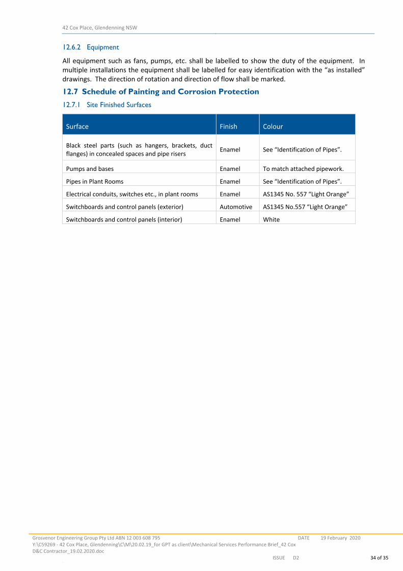
12.7.1 Site Finished Surfaces
Surface Finish Colour
Black steel parts (such as hangers, brackets, duct flanges) in concealed spaces and pipe risers
Enamel See “Identification of Pipes”.
Pumps and bases Enamel To match attached pipework.
Pipes in Plant Rooms Enamel See “Identification of Pipes”.
Electrical conduits, switches etc., in plant rooms Enamel AS1345 No. 557 “Light Orange”
Switchboards and control panels (exterior) Automotive AS1345 No.557 “Light Orange”
Switchboards and control panels (interior) Enamel White
42 Cox Place, Glendenning NSW
Grosvenor Engineering Group Pty Ltd ABN 12 003 608 795 Y:\C59269 ‐ 42 Cox Place, Glendenning\C\M\20.02.19_for GPT as client\Mechanical Services Performance Brief_42 CoxD&C Contractor_19.02.2020.doc
DATE 19 February 2020
ISSUE D2 35 of 35 LL
13 ANNEXURES
Warehouse ventilation – concept drawings
Offices ventilation and Air Conditioning – concept drawings
MECHANICAL SERVICES
WAREHOUSE 1 & 2 at
42 COX PLACE, GLENDENNING
DRAWING SCHEDULE
C59269-WH3-M01 MECHANICAL SERVICES LEGEND, GENERAL NOTES AND SCHEDULESC59269-WH3-M02 1:250
N.T.S.C59269-WH3-M00 MECHANICAL SERVICES COVER SHEET N.T.S.
MECHANICAL SERVICES WAREHOUSE 1 & 2 FLOOR LAYOUTC59269-WH3-M03 1:250C59269-WH3-M04 1:100MECHANICAL SERVICES WAREHOUSE 1 & 2 OFFICES FLOOR AND ROOF PLANS
MECHANICAL SERVICES WAREHOUSE 1 & 2 ROOF LAYOUT
C59269-WH3-M05 1:50MECHANICAL SERVICES PUMP ROOM
TO BE CONFIRMED
CHANGE NOTEDATEREVISION DESCRIPTIONREV.P1 PRELIMINARY 10.02.2020P2 FOR D & C TENDER 18.02.2020
Plotted Date
Date
Date
Date
Date
Client
Approved
Project
Drawn
Scale
Design
Co-ordinated
Title
RevisionDrawing Number
The GPT Group
INDUSTRIAL DEVELOPMENTat42 COX PLACE, GLENDENNING
MECHANICAL SERVICESCOVER SHEET & DRAWING SCHEDULE
P2C59269-M00
Scale: NTS @ B1
SAK 24.01.2020
SAK 30.01.2020 SAK
PRELIMINARY
NOT FOR
CONSTRUCTION
SW
A
M
LEGENDUNINSULATED NEW DUCTWORK
EXISTING SERVICES TO REMAIN
FLEXIBLE DUCTWORK
REFRIGERANT PIPEWORK
CONDENSATE DRAINAGE PIPEWORK
DUCT SPIGOT WITH BUTTERFLY DAMPER (MOTORISED)
DUCT SPIGOT WITH BUTTERFLY DAMPER (MANUAL)
TUNDISH
RETURN / EXHAUST / INTAKE AIR
ACCESS PANEL IN CEILING
4-WAY BLOW LOUVRED FACE DIFFUSER
3-WAY BLOW LOUVRED FACE DIFFUSER
EXHAUST / RETURN AIR GRILLE
WALL MOUNTED TEMPERATURE SENSOR
DOOR GRILLE (REFER TO SCHEDULE)
CONDENSER UNIT HORIZONTAL DISCHARGE
EQUIPMENT LABEL
EXISTING SERVICES TO BE DEMOLISHED
INTERNALLY INSULATED NEW DUCTWORK (50mm THERMAL INSULATION)
INTERNALLY INSULATED NEW DUCTWORK (75mm THERMAL INSULATION)
INTERNALLY INSULATED NEW DUCTWORK (100mm THERMAL INSULATION)
INTERNALLY INSULATED NEW DUCTWORK (50mm ACOUSTIC INSULATION)
EXTERNALLY INSULATED NEW DUCTWORK (100mm ACOUSTIC INSULATION)
FLOOR WASTE
RADIAL SWIRL DIFFUSER
SUPPLY / DISCHARGE AIR
T ABOVE CEILING TEMPERATURE SENSOR
CP WALL MOUNTED AC CONTROL PANEL
ABBREVIATIONS
AC
AHUAF
CEF
CH
CHWF & R
A/P
CU
CWF & R
EF
EDH
FD
SUPPLY AIR FAN
TUNDISH
TOILET EXHAUST FAN
STAIR PRESSURISATION FAN
UNLESS NOTED OTHERWISEVOLUME CONTROL DAMPER
FIRE DAMPER
ELECTRIC DUCT HEATER
EXHAUST FAN
TD
VCDU.N.O.
TEF
SPF
SAF
FROM BELOW
GARBAGE EXHAUST FAN
KITCHEN EXHAUST FAN
MOTORISED FIRE DAMPER
MOTOR CONTROL CENTRE
NON RETURN DAMPER
OPPOSED BLADE DAMPER
CONDENSER WATER FLOW AND RETURN
CONDENSING UNIT
CHILLED WATER FLOW AND RETURN
CHILLER
CAR PARK EXHAUST FAN
OBD
NRD
MFD
MCC
KEF
AIR FILTER
ACCESS PANEL
AIR HANDLING UNIT
AIR CONDITIONING UNIT
GEF
F/B
SD SMOKE DAMPER
HIGH LEVELH.L.
KITCHEN SUPPLY FANKSF
MOTORISED VOLUME CONTROL DAMPERMVCD
D CONDENSATE DRAIN
TO BELOWT/B
TO ABOVET/A
FROM ABOVEF/A
FLOOR WASTEFW
LOW LEVELL.L.
EQUIPMENT DESIGNATION
C/W COMPLETE WITH
E/A EXHAUST AIR
S.DN SET DOWN
S.UP SET UP
B BOILER
CT COOLING TOWER
SMOKE EXHAUST FANSEF
PACKAGED AIR CONDITIONING UNITPAC
ATT ATTENUATOR
OUTSIDE AIR FANOAF
CHWP CHILLED WATER PUMP
CWP CONDENSER WATER PUMP
HE HEAT EXCHANGER
HWP HOT WATER PUMP
OUTSIDE AIRO/A
DEEP BED FILTER
FLAT ON TOPFOT
FLAT ON BOTTOMFOB
SUPPLY AIRS/A
RETURN AIRR/A
SIDE WALL GRILLE / WEATHERPROOF LOUVRE
EQUIPMENT FLEXIBLE CONNECTION
UC DOOR UNDER-CUT : 25mm BY BUILDER
OPEN END - EXHAUST/RETURN AIR DUCT
MITRE BEND WITH TURNING VANES(AIRFOIL BLADES)
SPLITTER DAMPERBRANCH DUCT CONNECTION WITH
OPEN END - SUPPLY AIR DUCT
OVAL DUCTWORK.SIDE A x SIDE B.
RECTANGULAR DUCTWORK.SIDE A x SIDE B
RELIEF AIR TRANSFER GRILLES AND FLEXIBLE DUCT
INTERNALLY INSULATED ABOVE CEILING AIR TRANSFER DUCT
OPPOSITE BLADE DAMPER / NON-RETUN DAMPER
MOTORIZED DUCT DAMPER
GENERAL LEGEND
FCU FAN COIL UNITCU CONDENSING UNIT
OAF OUTSIDE AR FAN
ATT ATTENUATORHOT WATER PUMP
BL BOILER
CHILLER WATER PUMPHEX HEAT EXCHANGER
CH CHILLER
SEF SMOKE EXHAUST FANSPF STAIR PRESSURISATION FAN
SE
CT COOLING TOWERACU AIR CONDITIONING UNIT
EAF EXHAUST AIR FAN
SAF SUPPLY AIR FAN
PAC PACKAGED AIR CONDITIONING UNIT
EQUIPMENT DESIGNATION
RSUPPLY AIR GRILLEEXHAUST AIR GRILLE
RETURN AIR GRILLE
EDH ELECTRIC DUCT HEATERCWP
FD FIRE DAMPER
UNDERCUT DOORUC
MSSB-1E MECHANICAL SERVICESSWITCHBOARD - ESSENTIAL No.1
SWITCHBOARD - NON ESSENTIAL No.1MECHANICAL SERVICESMSSB-1NE
OUTDOOR AIR
RETURN AIR
SUPPLY AIR
TO ABOVE
OA
RA
SA
TA
TUNDISH
TOILET EXHAUSTTE
TD
VCD
F.D.
D.
CWF,R
FIRE DAMPER
TO BELOWTB
ACCESS PANEL
EXHAUST AIR
FLOOR LEVEL
A/P
EA
FL
C/W
FROM ABOVE
FROM BELOW
HIGH LEVEL
LOW LEVEL
HL
LL
F/A
F/B
NRD
OBD
FLOOR WASTEFW
COMPLETE WITH
NON RETURN DAMPER
OPPOSED BLADE VOLUMECONTROL DAMPER
VOLUME CONTROL DAMPER
CONDENSATE DRAIN
CONDENSER WATER FLOW & RETURN
RPR-GR REFRIGERANT PIPE RISER SERVING GROUND FLOORTO BE TERMINATED AT GROUND FLOOR CEILING
FLAT ON TOPF.O.T.
FLAT ON BOTTOMF.O.B.
SET DOWNSD
SET UPSU
CFD CEILING FIRE DAMPER
TEF TOILET EXHAUST FAN
HWP
CONDENSER WATER PUMP
CHWP
FLEXIBLE DUCTWORKRETURN / EXHAUST AIR EGGCRATE GRILLESSUPPLY AIR DIFFUSERS LOUVRED TYPERADIAL SWIRL DIFFUSERS by KRANTZ (MODEL No. RA-N3)
JET DIFFUSER
18.
17.
FOR SHEETMETAL SIZES.
16. ALL FAN COIL UNITS TO BE HUNG WITH BROOKER ROD. METAL STRAP SHALL NOT BE ACCEPTED
15. MAINTAIN 150mm CLEARANCE ABOVE CEILING WHERE POSSIBLE FOR LIGHT FITTINGS
NOTES
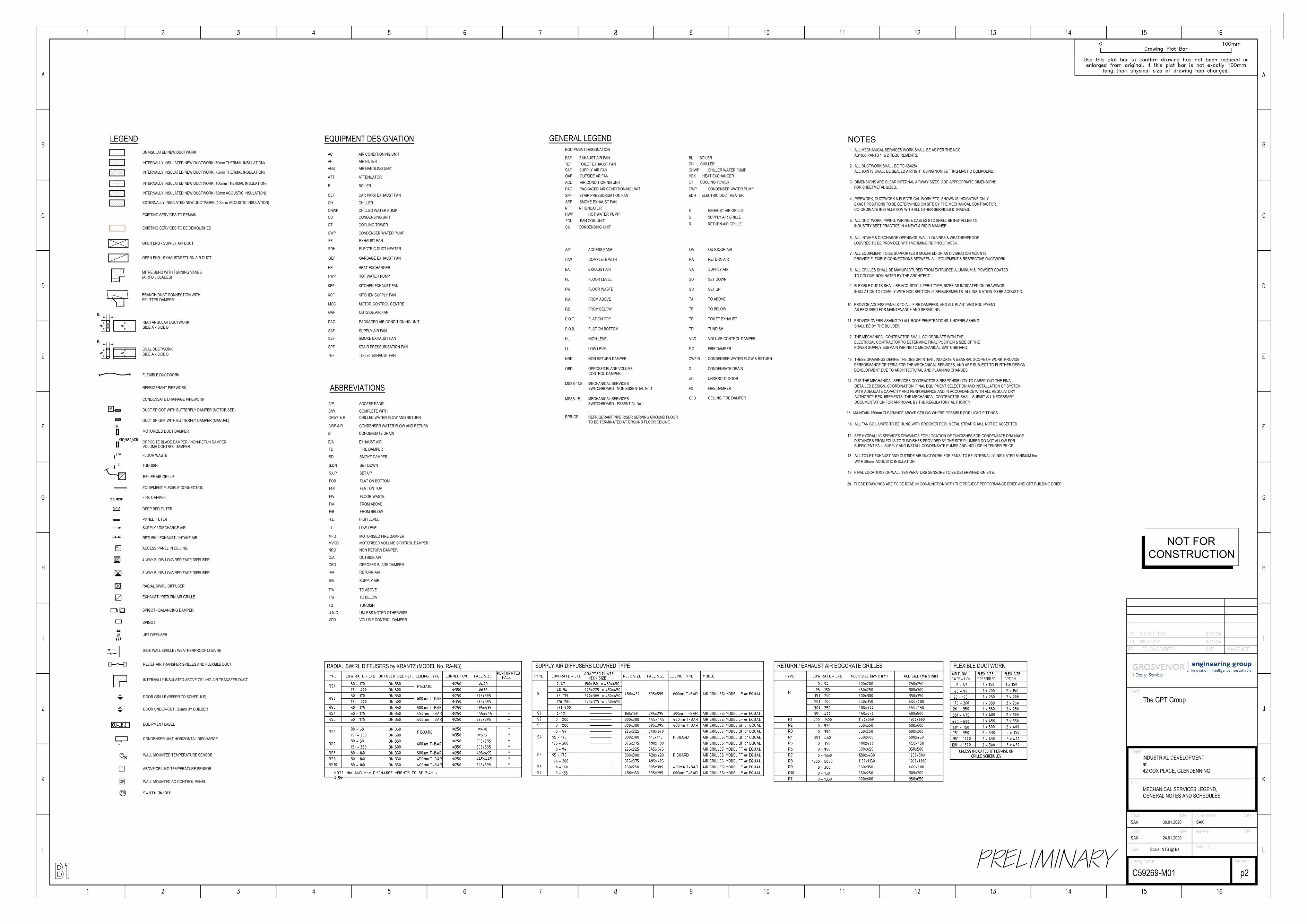
3. DIMENSIONS ARE CLEAR INTERNAL AIRWAY SIZES. ADD APPROPRIATE DIMENSIONS
ALL JOINTS SHALL BE SEALED AIRTIGHT USING NON-SETTING MASTIC COMPOUND.
CO-ORDINATE INSTALLATION WITH ALL OTHER SERVICES & TRADES.
INDUSTRY BEST PRACTICE IN A NEAT & RIGID MANNER.
6. ALL INTAKE & DISCHARGE OPENINGS, WALL LOUVRES & WEATHERPROOF
12. THE MECHANICAL CONTRACTOR SHALL CO-ORDINATE WITH THE
POWER SUPPLY SUBMAIN WIRING TO MECHANICAL SWITCHBOARD.
1. ALL MECHANICAL SERVICES WORK SHALL BE AS PER THE NCC,
2. ALL DUCTWORK SHALL BE TO AS4254.
4. PIPEWORK, DUCTWORK & ELECTRICAL WORK ETC. SHOWN IS INDICATIVE ONLY.EXACT POSITIONS TO BE DETERMINED ON SITE BY THE MECHANICAL CONTRACTOR.
5. ALL DUCTWORK, PIPING, WIRING & CABLES ETC SHALL BE INSTALLED TO
7. ALL EQUIPMENT TO BE SUPPORTED & MOUNTED ON ANTI-VIBRATION MOUNTS.PROVIDE FLEXIBLE CONNECTIONS BETWEEN ALL EQUIPMENT & RESPECTIVE DUCTWORK.
11. PROVIDE OVERFLASHING TO ALL ROOF PENETRATIONS. UNDERFLASHING
ELECTRICAL CONTRACTOR TO DETERMINE FINAL POSITION & SIZE OF THE
SHALL BE BY THE BUILDER.
LOUVRES TO BE PROVIDED WITH VERMIN/BIRD PROOF MESH.
AS1668 PARTS 1 & 2 REQUIREMENTS.
9. FLEXIBLE DUCTS SHALL BE ACOUSTIC 4-ZERO TYPE, SIZES AS INDICATED ON DRAWINGS.
TO COLOUR NOMINATED BY THE ARCHITECT.
10. PROVIDE ACCESS PANELS TO ALL FIRE DAMPERS, AND ALL PLANT AND EQUIPMENTAS REQUIRED FOR MAINTENANCE AND SERVICING.
8. ALL GRILLES SHALL BE MANUFACTURED FROM EXTRUDED ALUMINUM & POWDER COATED
DEVELOPMENT DUE TO ARCHITECTURAL AND PLANNING CHANGES.
DOCUMENTATION FOR APPROVAL BY THE REGULATORY AUTHORITY.
13. THESE DRAWINGS DEFINE THE DESIGN INTENT, INDICATE A GENERAL SCOPE OF WORK, PROVIDEPERFORMANCE CRITERIA FOR THE MECHANICAL SERVICES, AND ARE SUBJECT TO FURTHER DESIGN
14. IT IS THE MECHANICAL SERVICES CONTRACTOR'S RESPONSIBILITY TO CARRY OUT THE FINALDETAILED DESIGN, COORDINATION, FINAL EQUIPMENT SELECTION AND INSTALLATION OF SYSTEMWITH ADEQUATE CAPACITY AND PERFORMANCE AND IN ACCORDANCE WITH ALL REGULATORYAUTHORITY REQUIREMENTS. THE MECHANICAL CONTRACTOR SHALL SUBMIT ALL NECESSARY
SEE HYDRAULIC SERVICES DRAWINGS FOR LOCATION OF TUNDISHES FOR CONDENSATE DRAINAGE.DISTANCES FROM FCU'S TO TUNDISHES PROVIDED BY THE SITE PLUMBER DO NOT ALLOW FOR SUFFICIENT FALL SUPPLY AND INSTALL CONDENSATE PUMPS AND INCLUDE IN TENDER PRICE.
ALL TOILET EXHAUST AND OUTSIDE AIR DUCTWORK FOR FANS TO BE INTERNALLY INSULATED MINIMUM 5m
19. FINAL LOCATIONS OF WALL TEMPERATURE SENSORS TO BE DETERMINED ON SITE.
20. THESE DRAWINGS ARE TO BE READ IN CONJUNCTION WITH THE PROJECT PERFORMANCE BRIEF AND GPT BUILDING BRIEF
INSULATION TO COMPLY WITH NCC SECTION-J5 REQUIREMENTS. ALL INSULATION TO BE ACOUSTIC.
WITH 50mm. ACOUSTIC INSULATION.
RELIEF AIR GRILLE
SPIGOT - BALANCING DAMPER
SPIGOT
VOLUME CONTROL DAMPER
CHANGE NOTEDATEREVISION DESCRIPTIONREV.P1 PRELIMINARY 10.02.2020P2 FOR D & C TENDER 18.02.2020
Plotted Date
Date
Date
Date
Date
Client
Approved
Project
Drawn
Scale
Design
Co-ordinated
Title
RevisionDrawing Number
The GPT Group
INDUSTRIAL DEVELOPMENTat42 COX PLACE, GLENDENNING
MECHANICAL SERVICES LEGEND,GENERAL NOTES AND SCHEDULES
p2C59269-M01
Scale: NTS @ B1
SAK 24.01.2020
SAK 30.01.2020 SAK
PRELIMINARY
NOT FOR
CONSTRUCTION

MAKE-UP AIR FREE AREA REQUIREMENT = MINIMUM 12 m2
THE MAKE-UP AIR OPENINGS:
- WEATHER LOUVERS
- PERFORATION RSDS OR COMBINATION OF ABOVE
SHALL BE EQUALLY SPACED ALONG THE FACADE. TOP
LEVEL OF THE OPENINGS SHALL BE BELOW 3.5M FFGL.
MAKE-UP AIR FREE AREA REQUIREMENT = MINIMUM 12 m2
THE MAKE-UP AIR OPENINGS:
- WEATHER LOUVERS
- PERFORATION RSDS OR COMBINATION OF ABOVE
SHALL BE EQUALLY SPACED ALONG THE FACADE. TOP
LEVEL OF THE OPENINGS SHALL BE BELOW 3.5M FFGL.
MAKE-UP AIR FREE AREA REQUIREMENT = MINIMUM 12 m2
THE MAKE-UP AIR OPENINGS:
- WEATHER LOUVERS
- PERFORATION RSDS OR COMBINATION OF ABOVE
SHALL BE EQUALLY SPACED ALONG THE FACADE. TOP
LEVEL OF THE OPENINGS SHALL BE BELOW 3.5M FFGL.
MAKE-UP AIR FREE AREA REQUIREMENT = MINIMUM 12 m2
THE MAKE-UP AIR OPENINGS:
- WEATHER LOUVERS
- PERFORATION RSDS OR COMBINATION OF ABOVE
SHALL BE EQUALLY SPACED ALONG THE FACADE. TOP
LEVEL OF THE OPENINGS SHALL BE BELOW 3.5M FFGL.
CHANGE NOTEDATEREVISION DESCRIPTIONREV.P1 PRELIMINARY 10.02.2020P2 FOR D & C TENDER 18.02.2020
Plotted Date
Date
Date
Date
Date
Client
Approved
Project
Drawn
Scale
Design
Co-ordinated
Title
RevisionDrawing Number
The GPT Group
INDUSTRIAL DEVELOPMENTat42 COX PLACE, GLENDENNING
MECHANICAL SERVICES DESIGN INTENTWAREHOUSE GROUND FLOOR LAYOUT
P2C59269-M02
Scale: 1:250 @ B1
SAK 24.01.2020
SAK 30.01.2020 SAK
PRELIMINARY
NOT FOR
CONSTRUCTION
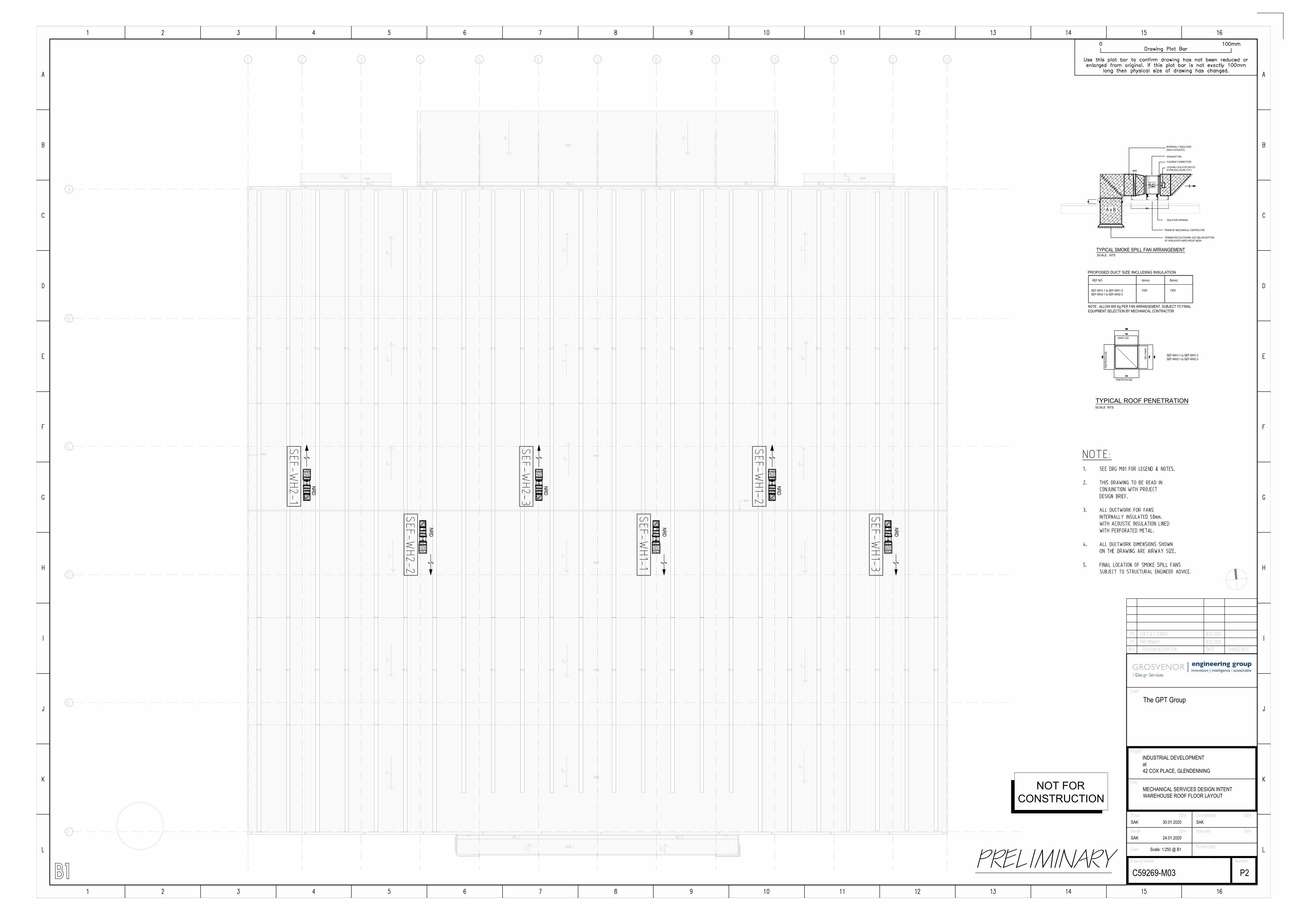
NRD
NRD
NRD
NRD
NRD
NRD
FRAME BY MECHANICAL CONTRACTOR
TERMINATED DUCTWORK JUST BELOW BOTTOMOF PURLIN WITH BIRD PROOF MESH
EXHAUST FAN
FLEXIBLE CONNECTION
ISOLATION SPRINGS
NRD
A x B
TYPICAL SMOKE SPILL FAN ARRANGEMENTSCALE : NTS
TYPICAL ROOF PENETRATION
SCALE NTS
INTERNALLY INSULATED(50mm ACOUSTIC)
PROPOSED DUCT SIZE INCLUDING INSULATION
LOCKABLE ISOLATOR SWITCHIN IP66 ENCLOSURE [TYP.]
PENETRATION SIZE
PENE
TRAT
ION S
IZE
AIRWAY SIZE
AIRWAY SIZE
NOTE : ALLOW 800 Kg PER FAN ARRANGEMENT. SUBJECT TO FINALEQUIPMENT SELECTION BY MECHANICAL CONTRACTOR
A(mm) B(mm)REF NO
SEF-WH1-1 to SEF-WH1-3SEF-WH2-1 to SEF-WH2-3
13001300SEF-WH1-1 to SEF-WH1-3SEF-WH2-1 to SEF-WH2-3
CHANGE NOTEDATEREVISION DESCRIPTIONREV.P1 PRELIMINARY 10.02.2020P2 FOR D & C TENDER 18.02.2020
Plotted Date
Date
Date
Date
Date
Client
Approved
Project
Drawn
Scale
Design
Co-ordinated
Title
RevisionDrawing Number
The GPT Group
INDUSTRIAL DEVELOPMENTat42 COX PLACE, GLENDENNING
MECHANICAL SERVICES DESIGN INTENTWAREHOUSE ROOF FLOOR LAYOUT
P2C59269-M03
Scale: 1:250 @ B1
SAK 24.01.2020
SAK 30.01.2020 SAK
PRELIMINARY
NOT FOR
CONSTRUCTION
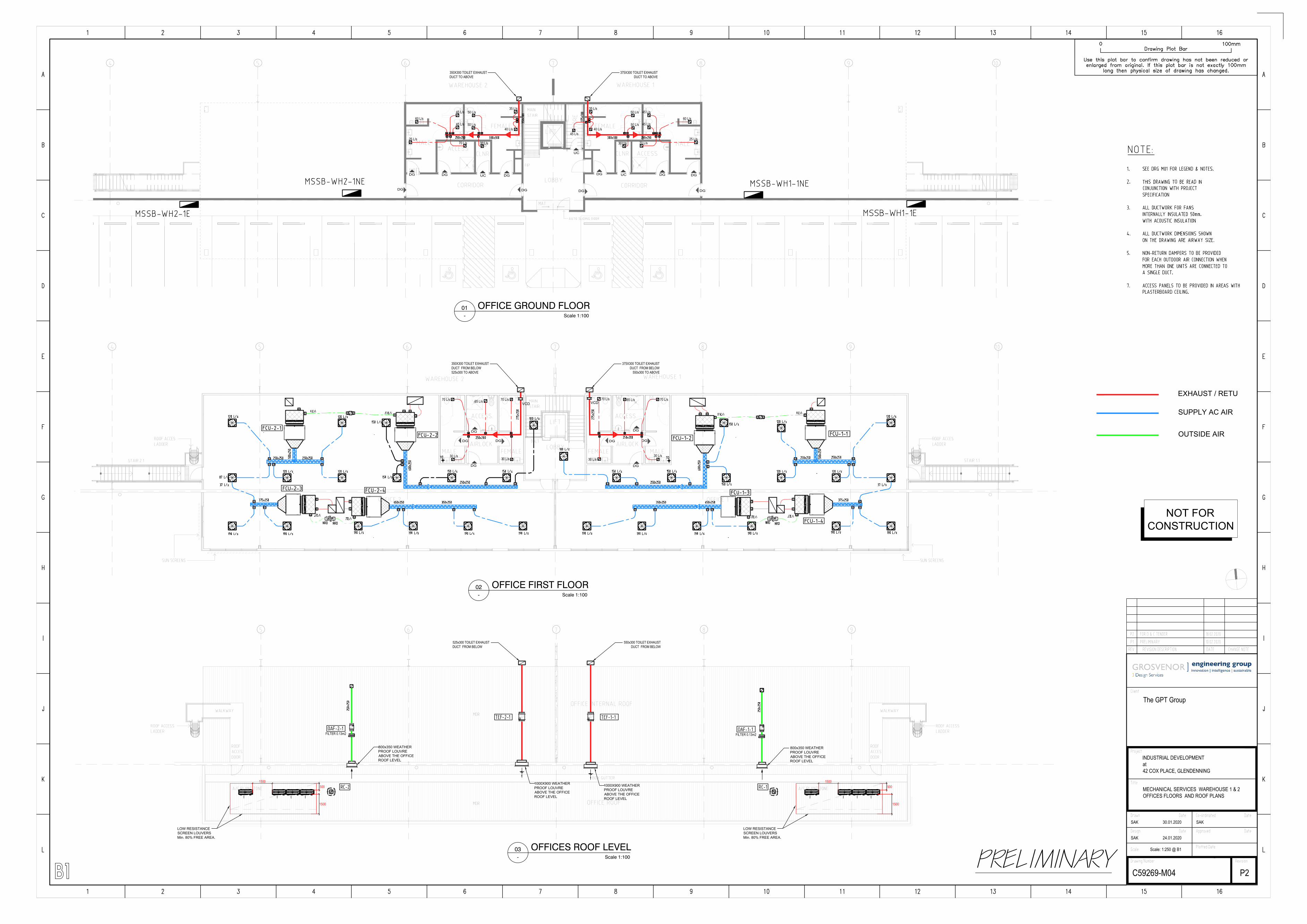
350X300 TOILET EXHAUST
DUCT TO ABOVE
375X300 TOILET EXHAUST
DUCT TO ABOVE
DG
DG
DG
45 L/s
UC
UC DG
DG
DG
DGDG
UC
30 L/s
60 L/s
70 L/s
45 L/s
45 L/s
50 L/s
50 L/s
35 L/s
40 L/s
25 L/s30 L/s
60 L/s
70 L/s
45 L/s
45 L/s
50 L/s
50 L/s
35 L/s
40 L/s
25 L/s
DG
DG
DG
350X300 TOILET EXHAUST
DUCT FROM BELOW
525x300 TO ABOVE
375X300 TOILET EXHAUST
DUCT FROM BELOW
550x300 TO ABOVE
DG
DGDG
DG
DGDG
DG
70 L/s
30 L/s
VCD
VCD
70 L/s
30 L/s
65 L/s70 L/s
30 L/s
70 L/s
30 L/s
65 L/s
525x300 TOILET EXHAUST
DUCT FROM BELOW
550x300 TOILET EXHAUST
DUCT FROM BELOW
1500500
1500
LOW RESISTANCE
SCREEN LOUVERS
Min. 80% FREE AREA.
1500500
1500
LOW RESISTANCE
SCREEN LOUVERS
Min. 80% FREE AREA.
1000X900 WEATHER
PROOF LOUVRE
ABOVE THE OFFICE
ROOF LEVEL
1000X900 WEATHER
PROOF LOUVRE
ABOVE THE OFFICE
ROOF LEVEL
FILTER 0.13m2
FILTER 0.13m2
800x350 WEATHER
PROOF LOUVRE
ABOVE THE OFFICE
ROOF LEVEL
800x350 WEATHER
PROOF LOUVRE
ABOVE THE OFFICE
ROOF LEVEL
EXHAUST / RETURN AIR
SUPPLY AC AIR
OUTSIDE AIR
CHANGE NOTEDATEREVISION DESCRIPTIONREV.P1 PRELIMINARY 10.02.2020P2 FOR D & C TENDER 18.02.2020
Plotted Date
Date
Date
Date
Date
Client
Approved
Project
Drawn
Scale
Design
Co-ordinated
Title
RevisionDrawing Number
The GPT Group
INDUSTRIAL DEVELOPMENTat42 COX PLACE, GLENDENNING
MECHANICAL SERVICES WAREHOUSE 1 & 2OFFICES FLOORS AND ROOF PLANS
P2C59269-M04
Scale: 1:250 @ B1
SAK 24.01.2020
SAK 30.01.2020 SAK
Scale 1:100
OFFICE GROUND FLOOR-
01
Scale 1:100
OFFICE FIRST FLOOR-
02
Scale 1:100
OFFICES ROOF LEVEL-
03
PRELIMINARY
NOT FOR
CONSTRUCTION