Embed Size (px)
Citation preview
¶(9pt)
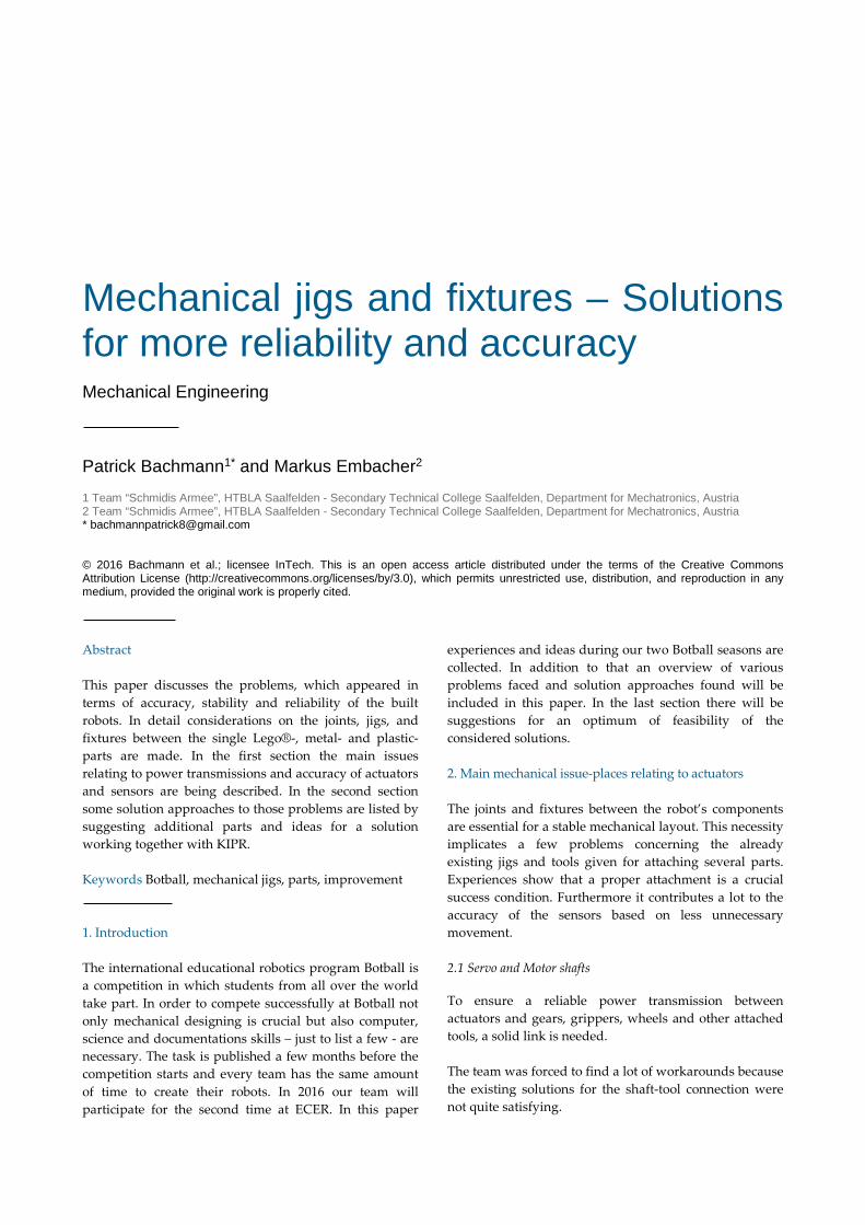
Mechanical jigs and fixtures – Solutions for more reliability and accuracy ¶(10pt) Mechanical Engineering ¶(12pt)
¶(18pt) Patrick Bachmann1* and Markus Embacher2 ¶(9 pt) 1 Team “Schmidis Armee”, HTBLA Saalfelden - Secondary Technical College Saalfelden, Department for Mechatronics, Austria 2 Team “Schmidis Armee”, HTBLA Saalfelden - Secondary Technical College Saalfelden, Department for Mechatronics, Austria * [email protected]
¶(16pt) © 2016 Bachmann et al.; licensee InTech. This is an open access article distributed under the terms of the Creative Commons Attribution License (http://creativecommons.org/licenses/by/3.0), which permits unrestricted use, distribution, and reproduction in any medium, provided the original work is properly cited.
¶(15pt) ¶(10ptAbstract
This paper discusses the problems, which appeared in
terms of accuracy, stability and reliability of the built
robots. In detail considerations on the joints, jigs, and
fixtures between the single Lego®-, metal- and plastic-
parts are made. In the first section the main issues
relating to power transmissions and accuracy of actuators
and sensors are being described. In the second section
some solution approaches to those problems are listed by
suggesting additional parts and ideas for a solution
working together with KIPR.
¶(9pt)
Keywords Botball, mechanical jigs, parts, improvement
(18pt) 1. Introduction
The international educational robotics program Botball is
a competition in which students from all over the world
take part. In order to compete successfully at Botball not
only mechanical designing is crucial but also computer,
science and documentations skills – just to list a few - are
necessary. The task is published a few months before the
competition starts and every team has the same amount
of time to create their robots. In 2016 our team will
participate for the second time at ECER. In this paper
experiences and ideas during our two Botball seasons are
collected. In addition to that an overview of various
problems faced and solution approaches found will be
included in this paper. In the last section there will be
suggestions for an optimum of feasibility of the
considered solutions.
2. Main mechanical issue-places relating to actuators
The joints and fixtures between the robot’s components
are essential for a stable mechanical layout. This necessity
implicates a few problems concerning the already
existing jigs and tools given for attaching several parts.
Experiences show that a proper attachment is a crucial
success condition. Furthermore it contributes a lot to the
accuracy of the sensors based on less unnecessary
movement.
2.1 Servo and Motor shafts To ensure a reliable power transmission between
actuators and gears, grippers, wheels and other attached
tools, a solid link is needed.
The team was forced to find a lot of workarounds because
the existing solutions for the shaft-tool connection were
not quite satisfying.
Collected problems relating to this topic:
• no reliability and unstable attachment
• bad concentricity
• bad axial true run
• overused gears
• overused axles
• overused jigs
These points will be discussed in the following.
2.1.1 Not reliable and unstable attachment
As said before the major problem is to attach the motor or
servo shaft to the parts that need to be powered. In most
cases this is a gear or an axle. Experiences show that the
reliability of the used fixtures is at a low level. This means
that before each run of the robot one team member has to
test the attachments of all actuators in order to prevent
movement inabilities during the run. Despite the
measures the attachments cannot always be prevented
from breaking due to unexpected crashes with other
robots or obstacles.
If this is the case there is no way to find back on track,
even with the best sensor and software failure-
compensation.
¶(4pt)
Figure 1. Used actuator-gear-connection, Right: built gripper,
Left: zoom to the crucial power transmission parts
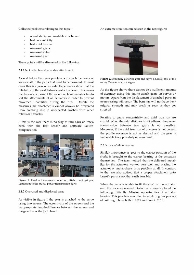
2.1.2 Overused and displaced parts
As visible in figure 1 the gear is attached to the servo
using two screws. The eccentricity of the screws and the
inappropriate length-difference between the screws and
the gear forces the jig to bend.
An extreme situation can be seen in the next figure:
Figure 2. Extremely distorted gear and servo-jig, Blue: axis of the
servo, Orange: axis of the gear
As the figure shows there cannot be a sufficient amount
of accuracy using this jigs to attach gears on servos or
motors. Apart from the displacement of attached parts an
overstressing will occur. The bent jigs will not have their
original strength and may break as soon as they get
stressed.
Relating to gears, concentricity and axial true run are
crucial. When the axial distance is not adhered the power
transmission between two gears is not possible.
Moreover, if the axial true run of one gear is not correct
the profile coverage is not as desired and the gear is
vulnerable to stop its duty or even break.
2.2 Servo and Motor bearing Similar importance as goes to the correct position of the
shafts is brought to the correct bearing of the actuators
themselves. The team noticed that the delivered metal-
jigs for the actuators worked very well and placing the
actuator on metal-sheets is no problem at all. In contrast
to that we also noticed that a proper attachment onto
Lego® - parts is not that easily feasible.
When the team was able to fit the shaft of the actuator
onto the place we wanted it to in many cases we faced the
following difficulty: Missing opportunities of actuator
bearing. This problem was often faced during our process
of building robots, both in 2015 and now in 2016.
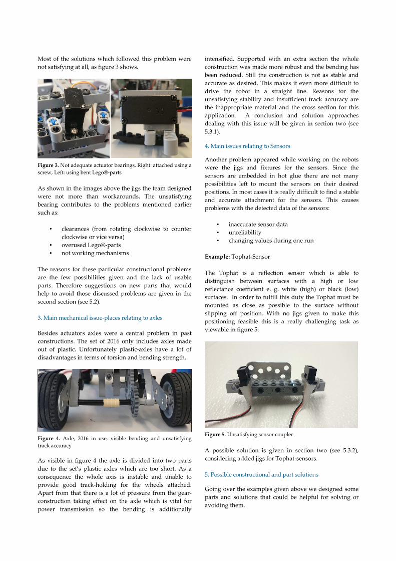
Most of the solutions which followed this problem were
not satisfying at all, as figure 3 shows.
Figure 3. Not adequate actuator bearings, Right: attached using a
screw, Left: using bent Lego®-parts
As shown in the images above the jigs the team designed
were not more than workarounds. The unsatisfying
bearing contributes to the problems mentioned earlier
such as:
• clearances (from rotating clockwise to counter
clockwise or vice versa)
• overused Lego®-parts
• not working mechanisms
The reasons for these particular constructional problems
are the few possibilities given and the lack of usable
parts. Therefore suggestions on new parts that would
help to avoid those discussed problems are given in the
second section (see 5.2).
3. Main mechanical issue-places relating to axles
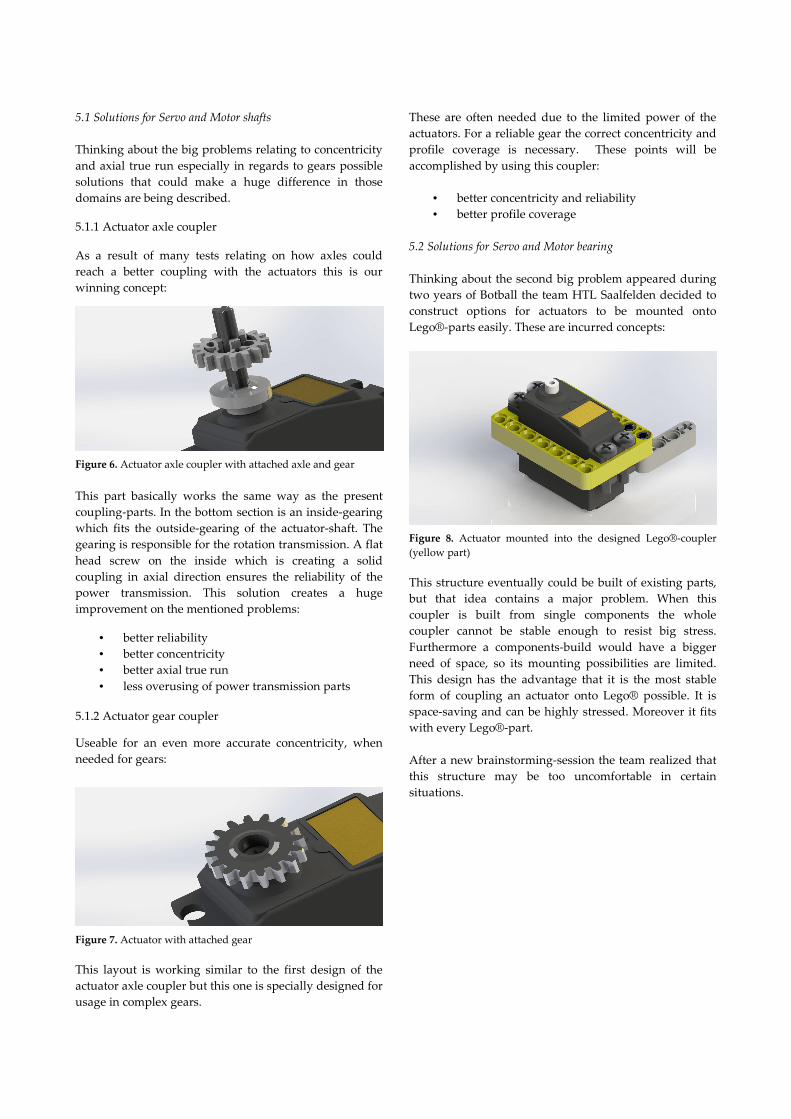
Besides actuators axles were a central problem in past
constructions. The set of 2016 only includes axles made
out of plastic. Unfortunately plastic-axles have a lot of
disadvantages in terms of torsion and bending strength.
Figure 4. Axle, 2016 in use, visible bending and unsatisfying
track accuracy
As visible in figure 4 the axle is divided into two parts
due to the set’s plastic axles which are too short. As a
consequence the whole axis is instable and unable to
provide good track-holding for the wheels attached.
Apart from that there is a lot of pressure from the gear-
construction taking effect on the axle which is vital for
power transmission so the bending is additionally
intensified. Supported with an extra section the whole
construction was made more robust and the bending has
been reduced. Still the construction is not as stable and
accurate as desired. This makes it even more difficult to
drive the robot in a straight line. Reasons for the
unsatisfying stability and insufficient track accuracy are
the inappropriate material and the cross section for this
application. A conclusion and solution approaches
dealing with this issue will be given in section two (see
5.3.1).
4. Main issues relating to Sensors
Another problem appeared while working on the robots
were the jigs and fixtures for the sensors. Since the
sensors are embedded in hot glue there are not many
possibilities left to mount the sensors on their desired
positions. In most cases it is really difficult to find a stable
and accurate attachment for the sensors. This causes
problems with the detected data of the sensors:
• inaccurate sensor data
• unreliability
• changing values during one run
Example: Tophat-Sensor
The Tophat is a reflection sensor which is able to
distinguish between surfaces with a high or low
reflectance coefficient e. g. white (high) or black (low)
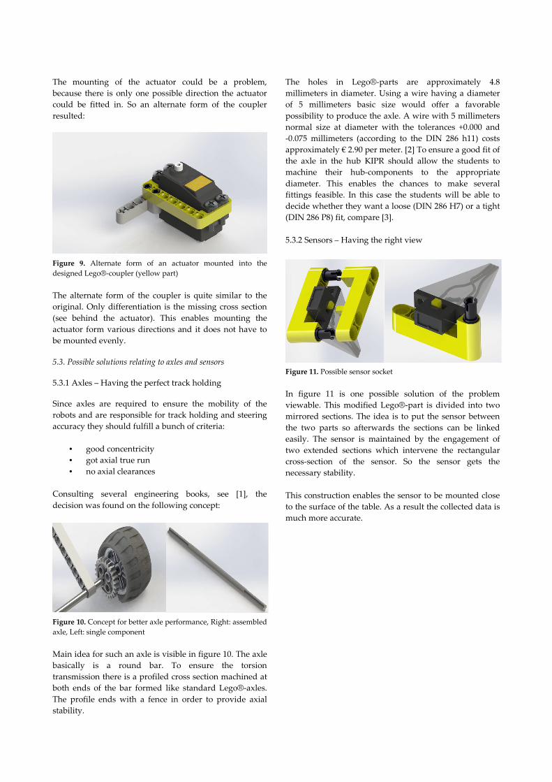
surfaces. In order to fulfill this duty the Tophat must be
mounted as close as possible to the surface without
slipping off position. With no jigs given to make this
positioning feasible this is a really challenging task as
viewable in figure 5:
Figure 5. Unsatisfying sensor coupler
A possible solution is given in section two (see 5.3.2),
considering added jigs for Tophat-sensors.
5. Possible constructional and part solutions
Going over the examples given above we designed some
parts and solutions that could be helpful for solving or
avoiding them.
5.1 Solutions for Servo and Motor shafts
Thinking about the big problems relating to concentricity
and axial true run especially in regards to gears possible
solutions that could make a huge difference in those
domains are being described.
5.1.1 Actuator axle coupler
As a result of many tests relating on how axles could
reach a better coupling with the actuators this is our
winning concept:
Figure 6. Actuator axle coupler with attached axle and gear
This part basically works the same way as the present
coupling-parts. In the bottom section is an inside-gearing
which fits the outside-gearing of the actuator-shaft. The
gearing is responsible for the rotation transmission. A flat
head screw on the inside which is creating a solid
coupling in axial direction ensures the reliability of the
power transmission. This solution creates a huge
improvement on the mentioned problems:
• better reliability
• better concentricity
• better axial true run
• less overusing of power transmission parts 5.1.2 Actuator gear coupler
Useable for an even more accurate concentricity, when
needed for gears:
Figure 7. Actuator with attached gear
This layout is working similar to the first design of the
actuator axle coupler but this one is specially designed for
usage in complex gears.
These are often needed due to the limited power of the
actuators. For a reliable gear the correct concentricity and
profile coverage is necessary. These points will be
accomplished by using this coupler:
• better concentricity and reliability
• better profile coverage
5.2 Solutions for Servo and Motor bearing
Thinking about the second big problem appeared during
two years of Botball the team HTL Saalfelden decided to
construct options for actuators to be mounted onto
Lego®-parts easily. These are incurred concepts:
Figure 8. Actuator mounted into the designed Lego®-coupler
(yellow part)
This structure eventually could be built of existing parts,
but that idea contains a major problem. When this
coupler is built from single components the whole
coupler cannot be stable enough to resist big stress.
Furthermore a components-build would have a bigger
need of space, so its mounting possibilities are limited.
This design has the advantage that it is the most stable
form of coupling an actuator onto Lego® possible. It is
space-saving and can be highly stressed. Moreover it fits
with every Lego®-part.
After a new brainstorming-session the team realized that
this structure may be too uncomfortable in certain
situations.
The mounting of the actuator could be a problem,
because there is only one possible direction the actuator
could be fitted in. So an alternate form of the coupler
resulted:
Figure 9. Alternate form of an actuator mounted into the
designed Lego®-coupler (yellow part)
The alternate form of the coupler is quite similar to the
original. Only differentiation is the missing cross section
(see behind the actuator). This enables mounting the
actuator form various directions and it does not have to
be mounted evenly.
5.3. Possible solutions relating to axles and sensors 5.3.1 Axles – Having the perfect track holding Since axles are required to ensure the mobility of the
robots and are responsible for track holding and steering
accuracy they should fulfill a bunch of criteria:
• good concentricity
• got axial true run
• no axial clearances
Consulting several engineering books, see [1], the
decision was found on the following concept:
Figure 10. Concept for better axle performance, Right: assembled
axle, Left: single component
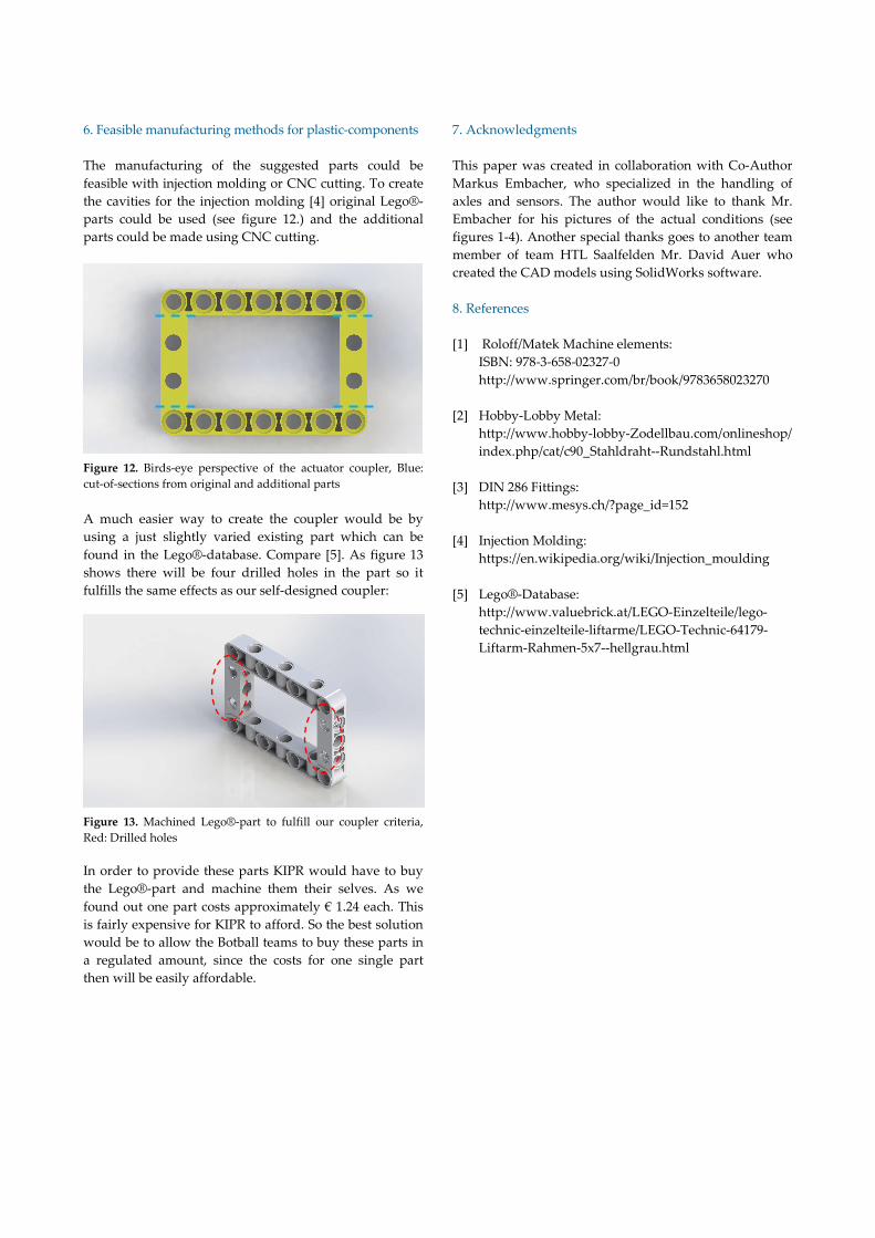
Main idea for such an axle is visible in figure 10. The axle
basically is a round bar. To ensure the torsion
transmission there is a profiled cross section machined at
both ends of the bar formed like standard Lego®-axles.
The profile ends with a fence in order to provide axial
stability.
The holes in Lego®-parts are approximately 4.8
millimeters in diameter. Using a wire having a diameter
of 5 millimeters basic size would offer a favorable
possibility to produce the axle. A wire with 5 millimeters
normal size at diameter with the tolerances +0.000 and
-0.075 millimeters (according to the DIN 286 h11) costs
approximately € 2.90 per meter. [2] To ensure a good fit of
the axle in the hub KIPR should allow the students to
machine their hub-components to the appropriate
diameter. This enables the chances to make several
fittings feasible. In this case the students will be able to
decide whether they want a loose (DIN 286 H7) or a tight
(DIN 286 P8) fit, compare [3].
5.3.2 Sensors – Having the right view
Figure 11. Possible sensor socket
In figure 11 is one possible solution of the problem
viewable. This modified Lego®-part is divided into two
mirrored sections. The idea is to put the sensor between
the two parts so afterwards the sections can be linked
easily. The sensor is maintained by the engagement of
two extended sections which intervene the rectangular
cross-section of the sensor. So the sensor gets the
necessary stability.
This construction enables the sensor to be mounted close
to the surface of the table. As a result the collected data is
much more accurate.
6. Feasible manufacturing methods for plastic-components
The manufacturing of the suggested parts could be
feasible with injection molding or CNC cutting. To create
the cavities for the injection molding [4] original Lego®-
parts could be used (see figure 12.) and the additional
parts could be made using CNC cutting.
Figure 12. Birds-eye perspective of the actuator coupler, Blue:
cut-of-sections from original and additional parts
A much easier way to create the coupler would be by
using a just slightly varied existing part which can be
found in the Lego®-database. Compare [5]. As figure 13
shows there will be four drilled holes in the part so it
fulfills the same effects as our self-designed coupler:
Figure 13. Machined Lego®-part to fulfill our coupler criteria,
Red: Drilled holes
In order to provide these parts KIPR would have to buy
the Lego®-part and machine them their selves. As we
found out one part costs approximately € 1.24 each. This
is fairly expensive for KIPR to afford. So the best solution
would be to allow the Botball teams to buy these parts in
a regulated amount, since the costs for one single part
then will be easily affordable.
7. Acknowledgments
¶(9pt)
This paper was created in collaboration with Co-Author
Markus Embacher, who specialized in the handling of
axles and sensors. The author would like to thank Mr.
Embacher for his pictures of the actual conditions (see
figures 1-4). Another special thanks goes to another team
member of team HTL Saalfelden Mr. David Auer who
created the CAD models using SolidWorks software.
¶(9pt)
8. References
[1] Roloff/Matek Machine elements:
ISBN: 978-3-658-02327-0
http://www.springer.com/br/book/9783658023270
[2] Hobby-Lobby Metal:
http://www.hobby-lobby-Zodellbau.com/onlineshop/
index.php/cat/c90_Stahldraht--Rundstahl.html
[3] DIN 286 Fittings:
http://www.mesys.ch/?page_id=152
[4] Injection Molding:
https://en.wikipedia.org/wiki/Injection_moulding
[5] Lego®-Database:
http://www.valuebrick.at/LEGO-Einzelteile/lego-
technic-einzelteile-liftarme/LEGO-Technic-64179-
Liftarm-Rahmen-5x7--hellgrau.html


![[Prakash Joshi] Jigs and Fixtures Design Manual](https://img.pdfslide.us/doc/110x75/55cf97a5550346d03392c551/prakash-joshi-jigs-and-fixtures-design-manual.jpg)