Embed Size (px)
Citation preview
MECHANICAL FUEL METER
OWNER’S MANUAL
WARNING: Read carefully and understand all INSTRUCTIONS before operating. Failure to follow the safety rules and other basic safety precautions may result in serious personal injury.
Item# 109623
Page 2 of 9
Thank you very much for choosing a NORTHERN TOOL + EQUIPMENT CO., INC. Product! For future reference, please complete the owner’s record below:
Model: _______________ Purchase Date: _______________ Save the receipt, warranty and these instructions. It is important that you read the entire manual to become familiar with this product before you begin using it.
This machine is designed for certain applications only. Northern Tool + Equipment cannot be responsible for issues arising from modification. We strongly recommend this machine is not modified and/or used for any application other than that for which it was designed. If you have any questions relative to a particular application, DO NOT use the machine until you have first contacted Northern Tool + Equipment to determine if it can or should be performed on the product.
For technical questions please call 1-800-222-5381.
INTENDED USE This Mechanical Fuel Meter can be used to measure the flow of kerosene, diesel oil, water or other fluids of low viscosity.
TECHNICAL SPECIFICATIONS Item No. 109623 Meter mechanism Nutating disk Flow rate range 5-32 GPM Operating pressure Max. 50 PSI Storage humidity Max. 95% Working temperature range 14-140°F Accuracy ±1% Inlet/Outlet connection 1" NPT Weight 1.8 KG
General Safety Regulations
WARNING: Read and understand all instructions. Failure to follow all instructions listed below may result in electric shock, fire and/or serious injury.
WARNING: The warnings, cautions, and instructions discussed in this instruction manual cannot cover all possible conditions or situations that could occur. It must be understood by the operator that common sense and caution are factors which cannot be built into this product, but must be supplied by the operator.
Page 3 of 9
SAVE THESE INSTRUCTIONS
WORK AREA å Keep work area clean, free of clutter and well lit. Cluttered and dark work areas can cause
accidents. å Keep children and bystanders away while operating a fuel meter. Distractions can cause you
to lose control, so visitors should remain at a safe distance from the work area. å Be aware of all power lines, electrical circuits, water pipes and other mechanical hazards in
your work area, particularly those hazards below the work surface hidden from the operator’s view that may be unintentionally contacted and may cause personal harm or property damage.
å Be alert of your surroundings. Using fuel meters in confined work areas may put you dangerously close to cutting tools and rotating parts.
PERSONAL SAFETY å Stay alert, watch what you are doing and use common sense when operating a fuel meter. Do
not use a fuel meter while you are tired or under the influence of drugs, alcohol or medication. å Dress properly. Do not wear loose clothing, dangling objects, or jewelry. Keep your hair,
clothing and gloves away from moving parts. Loose clothes, jewelry or long hair can be caught in moving parts. Air vents often cover moving parts and should be avoided.
å Use safety apparel and equipment. Use safety goggles or safety glasses with side shields which comply with current national standards, or when needed, a face shield. Use as dust mask in dusty work conditions. This applies to all persons in the work area. Also use non-skid safety shoes, hardhat, gloves, dust collection systems, and hearing protection when appropriate.
å Do not overreach. Keep proper footing and balance at all times.
INSTALLATION 1. The meter can be installed in any position, directly on rigid pipelines or flexible hoses, or directly on
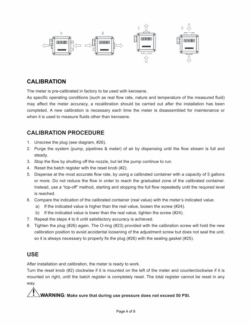
pumps or tanks. 2. The meter flow direction is fixed and indicated by an arrow. The meter is supplied in the standard
configuration (Figure A). 3. The counter and the cover can be rotated around the body in order to carry out the different
configurations (Figures B, C & D). 4. The reset knob can be installed either on the right side or on the left side of the meter in order to
modify the standard configuration, following the instructions provided in the section “Disassembly/Reassembly.”
5. The meter body is equipped with 4 blind holes which can be threaded for a possible fastening. If solid particles enter the measuring chamber the correct working of the nutating disk may be affected.
6. Always filter the fluid by installing a filter (included) on the meter inlet.
Page 4 of 9
CALIBRATION The meter is pre-calibrated in factory to be used with kerosene. As specific operating conditions (such as real flow rate, nature and temperature of the measured fluid) may affect the meter accuracy, a recalibration should be carried out after the installation has been completed. A new calibration is necessary each time the meter is disassembled for maintenance or when it is used to measure fluids other than kerosene.
CALIBRATION PROCEDURE 1. Unscrew the plug (see diagram, #26). 2. Purge the system (pump, pipelines & meter) of air by dispensing until the flow stream is full and
steady. 3. Stop the flow by shutting off the nozzle, but let the pump continue to run. 4. Reset the batch register with the reset knob (#2). 5. Dispense at the most accurate flow rate, by using a calibrated container with a capacity of 5 gallons
or more. Do not reduce the flow in order to reach the graduated zone of the calibrated container. Instead, use a “top-off” method, starting and stopping the full flow repeatedly until the required level is reached.
6. Compare the indication of the calibrated container (real value) with the meter’s indicated value. a) If the indicated value is higher than the real value, loosen the screw (#24). b) If the indicated value is lower than the real value, tighten the screw (#24).
7. Repeat the steps 4 to 6 until satisfactory accuracy is achieved. 8. Tighten the plug (#26) again. The O-ring (#23) provided with the calibration screw will hold the new
calibration position to avoid accidental loosening of the adjustment screw but does not seal the unit, so it is always necessary to properly fix the plug (#26) with the sealing gasket (#25).
USE After installation and calibration, the meter is ready to work. Turn the reset knob (#2) clockwise if it is mounted on the left of the meter and counterclockwise if it is mounted on right, until the batch register is completely reset. The total register cannot be reset in any way.
WARNING: Make sure that during use pressure does not exceed 50 PSI.
Page 5 of 9
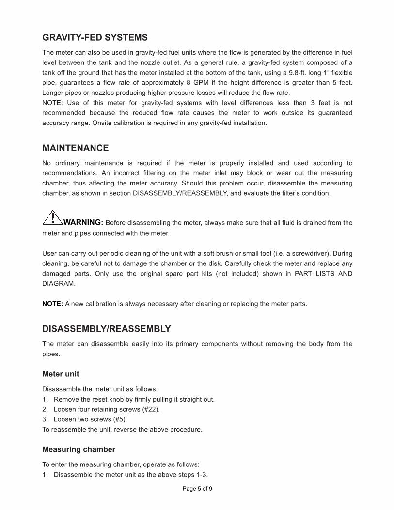
GRAVITY-FED SYSTEMS The meter can also be used in gravity-fed fuel units where the flow is generated by the difference in fuel level between the tank and the nozzle outlet. As a general rule, a gravity-fed system composed of a tank off the ground that has the meter installed at the bottom of the tank, using a 9.8-ft. long 1” flexible pipe, guarantees a flow rate of approximately 8 GPM if the height difference is greater than 5 feet. Longer pipes or nozzles producing higher pressure losses will reduce the flow rate. NOTE: Use of this meter for gravity-fed systems with level differences less than 3 feet is not recommended because the reduced flow rate causes the meter to work outside its guaranteed accuracy range. Onsite calibration is required in any gravity-fed installation.
MAINTENANCE No ordinary maintenance is required if the meter is properly installed and used according to recommendations. An incorrect filtering on the meter inlet may block or wear out the measuring chamber, thus affecting the meter accuracy. Should this problem occur, disassemble the measuring chamber, as shown in section DISASSEMBLY/REASSEMBLY, and evaluate the filter’s condition.
WARNING: Before disassembling the meter, always make sure that all fluid is drained from the meter and pipes connected with the meter. User can carry out periodic cleaning of the unit with a soft brush or small tool (i.e. a screwdriver). During cleaning, be careful not to damage the chamber or the disk. Carefully check the meter and replace any damaged parts. Only use the original spare part kits (not included) shown in PART LISTS AND DIAGRAM. NOTE: A new calibration is always necessary after cleaning or replacing the meter parts.
DISASSEMBLY/REASSEMBLY The meter can disassemble easily into its primary components without removing the body from the pipes. Meter unit
Disassemble the meter unit as follows: 1. Remove the reset knob by firmly pulling it straight out. 2. Loosen four retaining screws (#22). 3. Loosen two screws (#5). To reassemble the unit, reverse the above procedure. Measuring chamber
To enter the measuring chamber, operate as follows: 1. Disassemble the meter unit as the above steps 1-3.
Page 6 of 9
2. Loosen the eight screws (#7). 3. Remove the body cover (#6), together with the gear unit.
WARNING: Be careful not to damage the sealing gasket (#16). 4. Remove the whole measuring chamber (#27) by lifting it from the meter body and at the same time
pulling it back towards the inlet in order to remove the O-ring (#17) from its seat at the outlet. 5. Remove the O-ring (#17) and divide the measuring chamber (#27) into two half to check the inside
of the chamber containing the nutating disk. To reassemble the chamber, reverse the above procedure. Be sure to: 1. Verify that the nutating disk rotates freely in the assembled chamber. 2. Install the gaskets (#16, #17) properly after inspecting and lubricating them with grease. 3. Make sure that when reattaching the cover to the body of the meter, the nutating disk needle does
not hit the driving lever (#14), which must remain free to be moved by the disk needle. 4. Tighten the screws (#7) completely. Gear unit
To reach the gear unit components: 1. Remove the cover Assy. (#28). 2. Loosen the screws (#13). 3. Remove the plate (#12). Now all gears can be reached for inspection. 4. Should the gasket (#10) be replaced, remove the bevel gear (#8) from the shaft by pulling straight
out, and then remove the gear unit (#11) together with the shaft. To reassemble, reverse the above described procedure paying particular attention to:
1. Lubricating the O-ring with grease before installation. 2. Checking that the gear unit can rotate freely before reattaching the cover.
Page 7 of 9
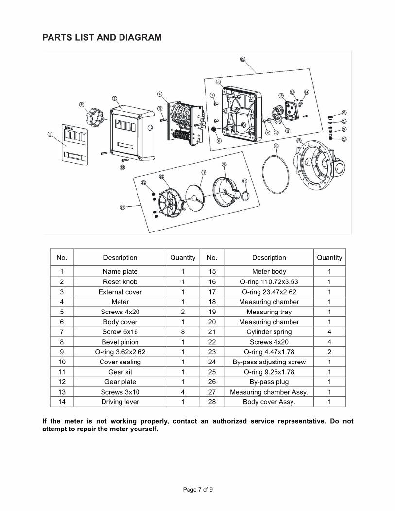
PARTS LIST AND DIAGRAM
No. Description Quantity No. Description Quantity
1 Name plate 1 15 Meter body 1 2 Reset knob 1 16 O-ring 110.72x3.53 1 3 External cover 1 17 O-ring 23.47x2.62 1 4 Meter 1 18 Measuring chamber 1 5 Screws 4x20 2 19 Measuring tray 1 6 Body cover 1 20 Measuring chamber 1 7 Screw 5x16 8 21 Cylinder spring 4 8 Bevel pinion 1 22 Screws 4x20 4 9 O-ring 3.62x2.62 1 23 O-ring 4.47x1.78 2
10 Cover sealing 1 24 By-pass adjusting screw 1 11 Gear kit 1 25 O-ring 9.25x1.78 1 12 Gear plate 1 26 By-pass plug 1 13 Screws 3x10 4 27 Measuring chamber Assy. 1 14 Driving lever 1 28 Body cover Assy. 1
If the meter is not working properly, contact an authorized service representative. Do not attempt to repair the meter yourself.
Page 8 of 9
MANUFACTURER’S LIMITED WARRANTY The limited warranty set forth below is given by Northern Tool + Equipment Company Inc., (NTE) with respect to new merchandise purchased and used in the United States, its possessions and territories. NTE warrants this product against defects in material and workmanship for a period of one (1) year commencing on the date of original purchase and will, at its option, repair or replace, free of charge, any part found to be defective in material or workmanship. This limited warranty shall only apply if this product has been operated and maintained in accordance with the Operator’s Manual furnished with the product, and has not been subject to misuse, abuse, commercial use, neglect, accident, improper maintenance, alteration, vandalism, theft, fire, water or damage because of other peril or natural disaster. Damage resulting from the installation or use of any accessory or attachment not approved by NTE for use with the products(s) covered by this manual will void your warranty as to any resulting damage. This warranty is limited to ninety (90) days from the date of original retail purchase for any NTE product that is used for rental or commercial purposes, or any other income-producing purposes. NTE reserves the right to change or improve the design of any NTE product without assuming any obligation to modify any product previously manufactured. No implied warranty, including any implied warranty of merchantability or fitness for a particular purpose, applies after the applicable period of express written warranty above as to the parts as identified. No other express warranty or guaranty, whether written or oral, except as mentioned above, given by any person or entity, including a dealer or retailer, with respect to any product shall bind NTE during the period of the Warranty, the exclusive remedy is repair or replacement of the product as set forth above. (Some states do not allow limitations on how long an implied warranty lasts, so the above limitation may not apply to you.) The provisions as set forth in this warranty provide the sole and exclusive remedy arising from the sales. NTE shall not be liable for incidental or consequential loss or damages including, without limitation, expenses incurred for substitute or related expenses, or for rental expenses to temporarily replace a warranted product. (Some states do not allow limitations on how long an implied warranty lasts, so the above limitation may not apply to you.) In no event shall recovery of any kind be greater than the amount of the purchase price of the product sold. Alteration of the safety features of the product shall void this warranty. You assume the risk and liability for loss, damage, or injury to you and your property and/or to others and their property arising out of the use or misuse or inability to use the product. This limited warranty shall not extend to anyone other than the original purchaser, original lessee or the person for whom it was purchased as a gift. How State Law Relates to this Warranty: This warranty gives you specific legal rights, and you may also have other rights which vary from state to state.
Page 9 of 9
For questions about your warranty, please call 1-800-222-5381.
Northern Tool + Equipment Co.,
2800 Southcross Drive West P.O. Box 1499 Burnsville, MN 55337-0499
Made in China