Embed Size (px)
Citation preview
Real Time Generator Fuel level Measurement
Meter Embedded with Ultrasound Sensor and
Data Acquisition System
Sadeque Reza Khan Department of Electronic and Communication Engineering
National Institute of Technology, Kernataka, India
Arifa Ferdousi
Department of Computer Science and Engineering
Varendra University, Rajshahi, Bangladesh
Siddique Reza Khan
Department of Computer Science and Engineering
MIST, Dhaka University, Dhaka, Bangladesh
Abstract—The use of Generator has become a very common
in almost every passive infrastructure companies, Industries,
hospitals, Townships etc, while by using these Generators, a
number of challenges are faced by the users and companies.
Among all other challenges fuel stealing from the generator
fuel tank has become an alarming issue as the price of the
fuel is touching sky high day by day. Although many
security and safety features are added but the fuel robbery
is still out of control and the loss of the companies are
immeasurable. So an advanced control system is designed
with the PIC microcontroller which can measure the level of
fuel in the fuel tank by using a high tech ultrasound sensor
and store the data in to a data acquisition system.
Index Terms—real time Clock; I2C; NT-TS601; FAT SPI;
PIC; RS232 one wire communication
I. INTRODUCTION
With the modernization of civilization generator has
become an important part of power generation source. At
any period of electricity crisis like inclement weather or
power cut because of electricity shortage a generator is
becoming most reliable source of power form big
industry to any small apartment [1] - [3] . Standby power
generation is a key component of a high availability
power system for data centres and network rooms where
generator systems with diesel or natural gas engines are
the best solution as with battery only short period of
power supply is possible [4]. Now-a-days generator
installation and its maintenance become a big issue as
most of the time generators are located in a remote places.
Manuscript received February 15, 2013; accepted June 7, 2013.
Although all the issues are alarming and can be given
most importance but in this project work the preference is
given to the unanticipated issue that is fuel theft from the
fuel tank of a generator as most of the generator
companies are counting a loss of millions of currencies
because of this unusual fuel loss. Diesel theft is an
international problem, with news of fuel theft are coming
from the modern countries like Australia, the UK and
New Zealand as well as across the US and in the
developing countries like India, Bangladesh etc fuel
stealing rate is incredibly high [5]. With the increasing
rate of fuel this issue of fuel theft has become a major
annoyance for the owner of different generator companies.
So to prevent this problem, different sensors like
capacitive sensor [6]-[9], WGM method [10], ultrasound
sensor [11], [12] etc are used. These sensors are really
helpful to prevent oil theft but problem is now-a-days oil
theft is done mostly by the officials. In most of the
generator sites the company used to supply the fuel for a
whole month as the majority of the generators are located
remotely. At the time of reload the fuel in the tank,
generator operator and the official person present at the
location are used to take away a superior quantity of
petroleum and in a manner that sensors could not identify
the mishap. As a result the company owners are still
counting loss in a large margin as they do not have any
data of how much quantity of petroleum is reloaded and
how much is used regularly and they are unable to blame
anyone because of less evidence against these robbers
present in the hand of those owners. To prevent this, a
microcontroller based measurement system is developed
which can accurately measure the fuel quantity and can
343©2013 Engineering and Technology Publishing
Journal of Automation and Control Engineering Vol. 1, No. 4, December 2013
doi: 10.12720/joace.1.4.343-348
store the data frequently with current time scale. So with
this control system owners can easily identify how much
fuel is reloaded and how much is used and also can point
out the missing rate of fuel from a generator site by
studying the data present in the data acquisition system.
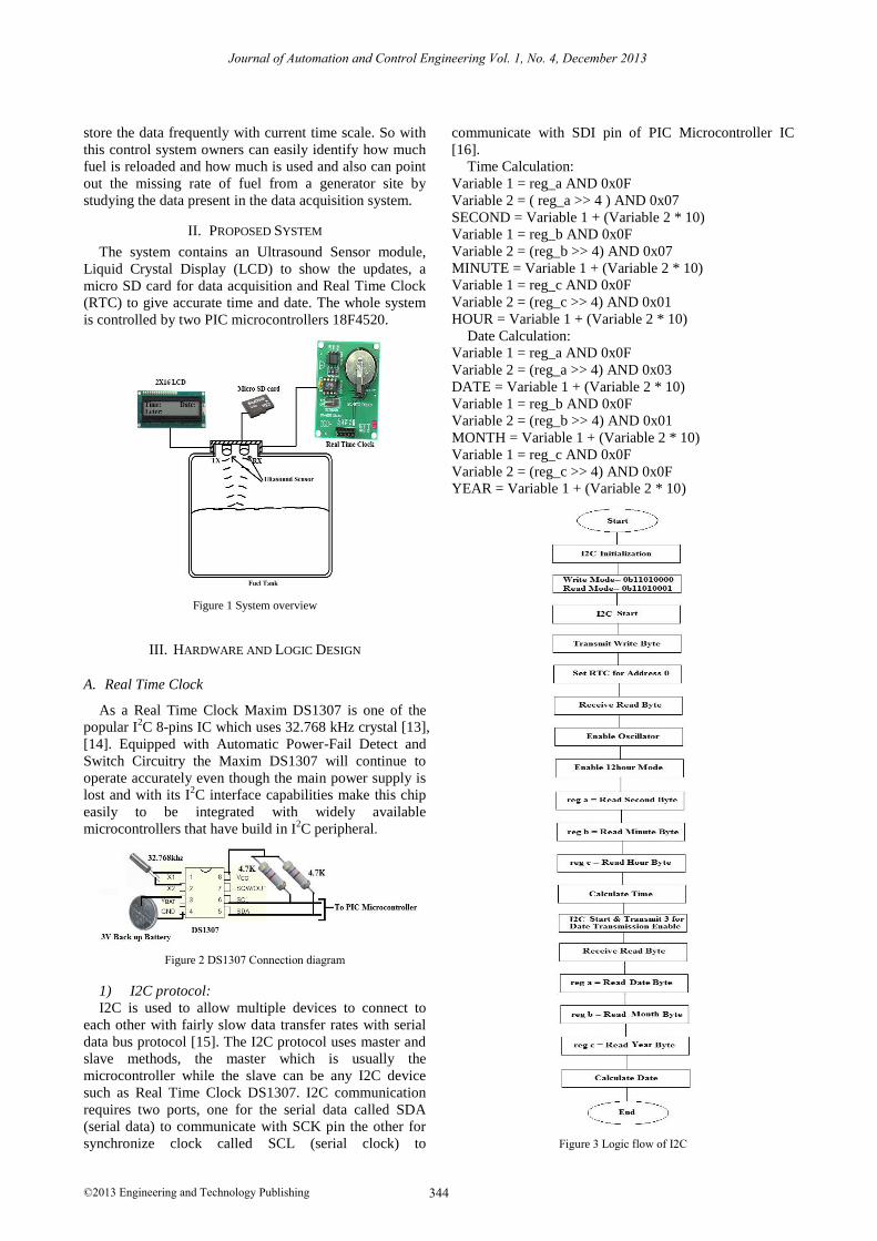
II. PROPOSED SYSTEM
The system contains an Ultrasound Sensor module,
Liquid Crystal Display (LCD) to show the updates, a
micro SD card for data acquisition and Real Time Clock
(RTC) to give accurate time and date. The whole system
is controlled by two PIC microcontrollers 18F4520.
Figure 1 System overview
III. HARDWARE AND LOGIC DESIGN
A. Real Time Clock
As a Real Time Clock Maxim DS1307 is one of the
popular I2C 8-pins IC which uses 32.768 kHz crystal [13],
[14]. Equipped with Automatic Power-Fail Detect and
Switch Circuitry the Maxim DS1307 will continue to
operate accurately even though the main power supply is
lost and with its I2C interface capabilities make this chip
easily to be integrated with widely available
microcontrollers that have build in I2C peripheral.
Figure 2 DS1307 Connection diagram
1) I2C protocol:
I2C is used to allow multiple devices to connect to
each other with fairly slow data transfer rates with serial
data bus protocol [15]. The I2C protocol uses master and
slave methods, the master which is usually the
microcontroller while the slave can be any I2C device
such as Real Time Clock DS1307. I2C communication
requires two ports, one for the serial data called SDA
(serial data) to communicate with SCK pin the other for
synchronize clock called SCL (serial clock) to
communicate with SDI pin of PIC Microcontroller IC
[16].
Time Calculation:
Variable 1 = reg_a AND 0x0F
Variable 2 = ( reg_a >> 4 ) AND 0x07
SECOND = Variable 1 + (Variable 2 * 10)
Variable 1 = reg_b AND 0x0F
Variable 2 = (reg_b >> 4) AND 0x07
MINUTE = Variable 1 + (Variable 2 * 10)
Variable 1 = reg_c AND 0x0F
Variable 2 = (reg_c >> 4) AND 0x01
HOUR = Variable 1 + (Variable 2 * 10)
Date Calculation:
Variable 1 = reg_a AND 0x0F
Variable 2 = (reg_a >> 4) AND 0x03
DATE = Variable 1 + (Variable 2 * 10)
Variable 1 = reg_b AND 0x0F
Variable 2 = (reg_b >> 4) AND 0x01
MONTH = Variable 1 + (Variable 2 * 10)
Variable 1 = reg_c AND 0x0F
Variable 2 = (reg_c >> 4) AND 0x0F
YEAR = Variable 1 + (Variable 2 * 10)
Figure 3 Logic flow of I2C
344©2013 Engineering and Technology Publishing
Journal of Automation and Control Engineering Vol. 1, No. 4, December 2013
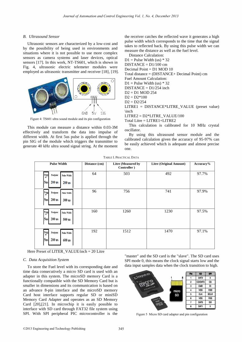
B. Ultrasound Sensor
Ultrasonic sensors are characterized by a low-cost and
by the possibility of being used in environments and
situations where it is not possible to use more complex
sensors as camera systems and laser devices, optical
sensors [17]. In this work, NT-TS601, which is shown in
Fig. 4, ultrasonic electric telemeter modules were
employed as ultrasonic transmitter and receiver [18], [19].
Figure 4: TS601 ultra sound module and its pin configuration
This module can measure a distance within 0.03-3M
effectively and transform the data into impulse of
different width. At first 5us pulse is applied through the
pin SIG of the module which triggers the transmitter to
generate 40 kHz ultra sound signal string. At the moment
the receiver catches the reflected wave it generates a high
pulse width which corresponds to the time that the signal
takes to reflected back. By using this pulse width we can
measure the distance as well as the fuel level.
Distance Calculation:
D1 = Pulse Width (us) * 32
DISTANCE = D1/100 cm
Decimal Point = D1 MOD 10
Total distance = (DISTANCE+ Decimal Point) cm
Fuel Amount Calculation:
D1 = Pulse Width (us) * 32
DISTANCE = D1/254 inch
D2 = D1 MOD 254
D2 = D2*100
D2 = D2/254
LITRE1 = DISTANCE*LITRE_VALUE (preset value)
\inch
LITRE2 = D2*LITRE_VALUE/100
Total Litre = LITRE1+LITRE2
This calculation is calibrated for 10 MHz crystal
oscillator.
By using this ultrasound sensor module and the
calibrated calculation given the accuracy of 95-97% can
be easily achieved which is adequate and almost precise
one.
TABLE I. PRACTICAL DATA
Pulse Width Distance (cm) Litre (Measured by
Controller )
Litre (Original Amount) Accuracy%
64 503 492 97.7%
96 756 741 97.9%
160 1260 1230 97.5%
192 1512 1470 97.1%
Here Preset of LITER_VALUE/inch = 20 Litre
C. Data Acquisition System
To store the Fuel level with its corresponding date and
time data consecutively a micro SD card is used with an
adapter in this system. The microSD memory Card is a
functionally compatible with the SD Memory Card but is
smaller in dimensions and its communication is based on
an advance 8-pin interface and the microSD memory
Card host interface supports regular SD or miniSD
Memory Card Adapter and operates as an SD Memory
Card [20],[21]. In microchip it is easily possible to
interface with SD card through FAT32 file system using
SPI. With SPI peripheral PIC microcontroller is the
"master" and the SD card is the "slave". The SD card uses
SPI mode 0, this means the clock signal starts low and the
data input samples data when the clock transition to high.
Figure 5 Micro SD card adapter and pin configuration
345©2013 Engineering and Technology Publishing
Journal of Automation and Control Engineering Vol. 1, No. 4, December 2013
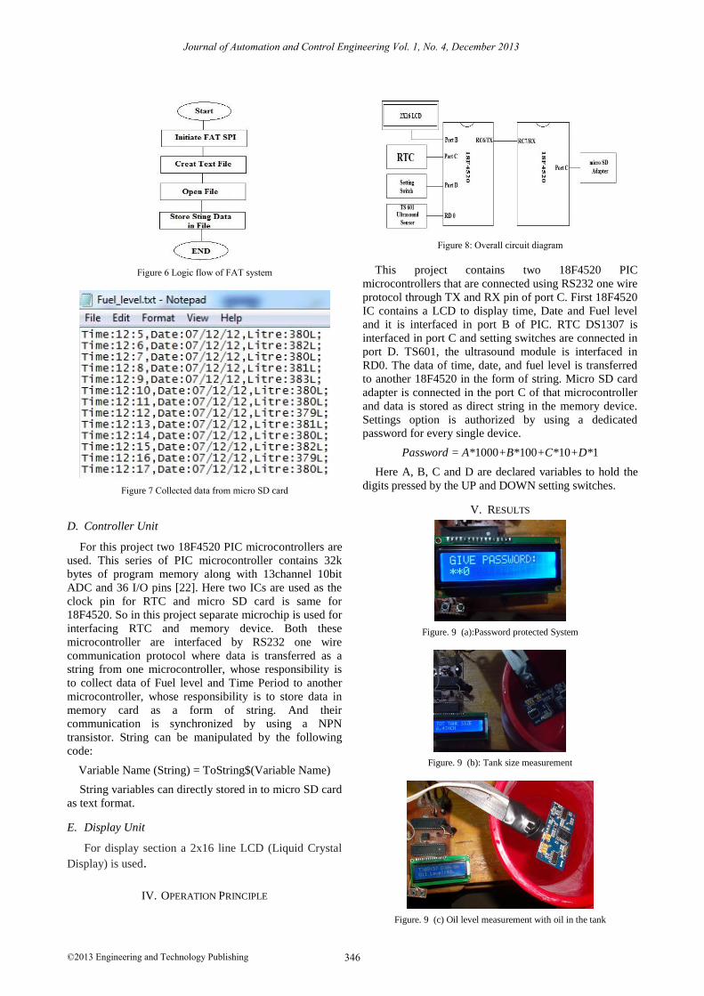
Figure 6 Logic flow of FAT system
Figure 7 Collected data from micro SD card
D. Controller Unit
For this project two 18F4520 PIC microcontrollers are
used. This series of PIC microcontroller contains 32k
bytes of program memory along with 13channel 10bit
ADC and 36 I/O pins [22]. Here two ICs are used as the
clock pin for RTC and micro SD card is same for
18F4520. So in this project separate microchip is used for
interfacing RTC and memory device. Both these
microcontroller are interfaced by RS232 one wire
communication protocol where data is transferred as a
string from one microcontroller, whose responsibility is
to collect data of Fuel level and Time Period to another
microcontroller, whose responsibility is to store data in
memory card as a form of string. And their
communication is synchronized by using a NPN
transistor. String can be manipulated by the following
code:
Variable Name (String) = ToString$(Variable Name)
String variables can directly stored in to micro SD card
as text format.
E. Display Unit
For display section a 2x16 line LCD (Liquid Crystal
Display) is used.
IV. OPERATION PRINCIPLE
Figure 8: Overall circuit diagram
This project contains two 18F4520 PIC
microcontrollers that are connected using RS232 one wire
protocol through TX and RX pin of port C. First 18F4520
IC contains a LCD to display time, Date and Fuel level
and it is interfaced in port B of PIC. RTC DS1307 is
interfaced in port C and setting switches are connected in
port D. TS601, the ultrasound module is interfaced in
RD0. The data of time, date, and fuel level is transferred
to another 18F4520 in the form of string. Micro SD card
adapter is connected in the port C of that microcontroller
and data is stored as direct string in the memory device.
Settings option is authorized by using a dedicated
password for every single device.
Password = A*1000+B*100+C*10+D*1
Here A, B, C and D are declared variables to hold the
digits pressed by the UP and DOWN setting switches.
V. RESULTS
Figure. 9 (a):Password protected System
Figure. 9 (b): Tank size measurement
Figure. 9 (c) Oil level measurement with oil in the tank
346©2013 Engineering and Technology Publishing
Journal of Automation and Control Engineering Vol. 1, No. 4, December 2013
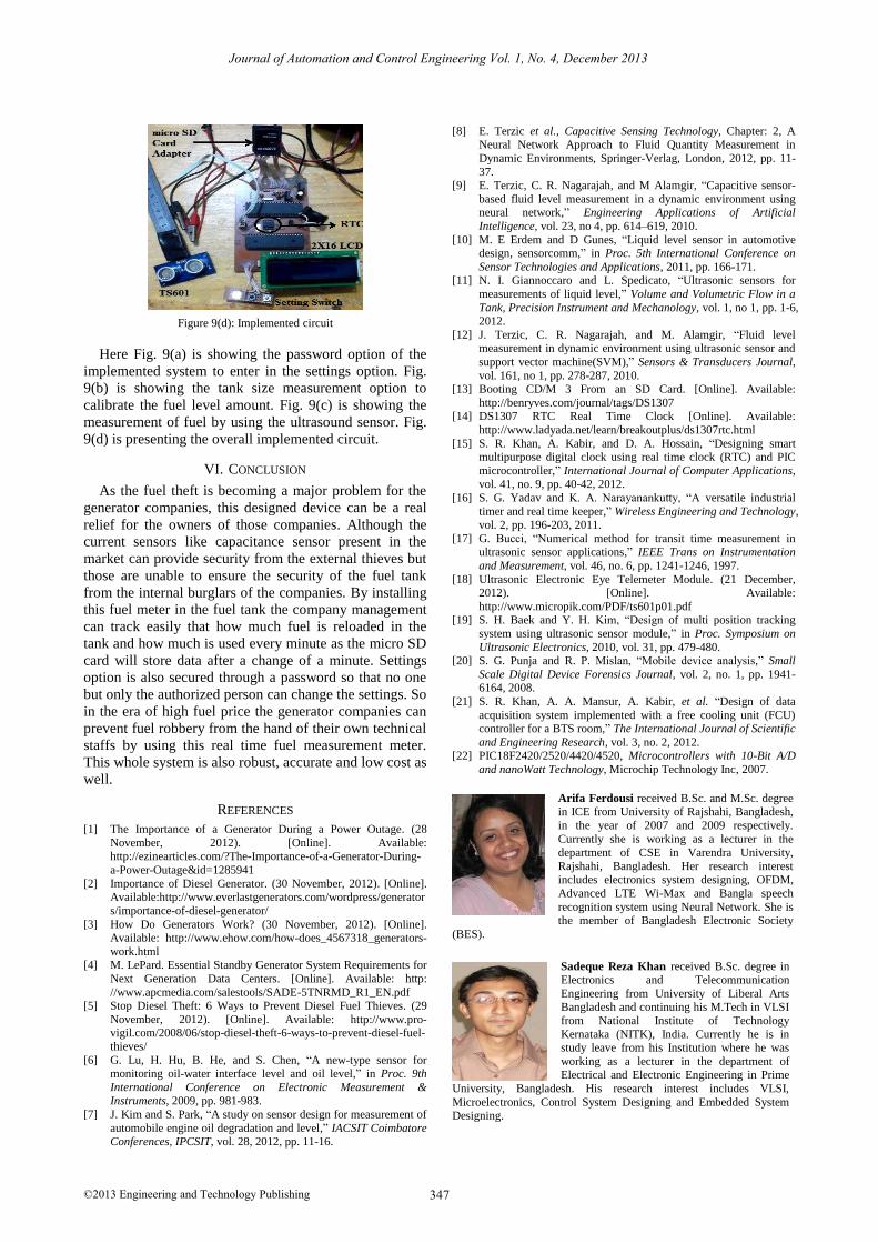
Figure 9(d): Implemented circuit
Here Fig. 9(a) is showing the password option of the
implemented system to enter in the settings option. Fig.
9(b) is showing the tank size measurement option to
calibrate the fuel level amount. Fig. 9(c) is showing the
measurement of fuel by using the ultrasound sensor. Fig.
9(d) is presenting the overall implemented circuit.
VI. CONCLUSION
As the fuel theft is becoming a major problem for the
generator companies, this designed device can be a real
relief for the owners of those companies. Although the
current sensors like capacitance sensor present in the
market can provide security from the external thieves but
those are unable to ensure the security of the fuel tank
from the internal burglars of the companies. By installing
this fuel meter in the fuel tank the company management
can track easily that how much fuel is reloaded in the
tank and how much is used every minute as the micro SD
card will store data after a change of a minute. Settings
option is also secured through a password so that no one
but only the authorized person can change the settings. So
in the era of high fuel price the generator companies can
prevent fuel robbery from the hand of their own technical
staffs by using this real time fuel measurement meter.
This whole system is also robust, accurate and low cost as
well.
REFERENCES
[1] The Importance of a Generator During a Power Outage. (28
November, 2012). [Online]. Available:
http://ezinearticles.com/?The-Importance-of-a-Generator-During-
a-Power-Outage&id=1285941
[2] Importance of Diesel Generator. (30 November, 2012). [Online]. Available:http://www.everlastgenerators.com/wordpress/generator
s/importance-of-diesel-generator/
[3] How Do Generators Work? (30 November, 2012). [Online]. Available: http://www.ehow.com/how-does_4567318_generators-
work.html [4] M. LePard. Essential Standby Generator System Requirements for
Next Generation Data Centers. [Online]. Available: http:
//www.apcmedia.com/salestools/SADE-5TNRMD_R1_EN.pdf [5] Stop Diesel Theft: 6 Ways to Prevent Diesel Fuel Thieves. (29
November, 2012). [Online]. Available: http://www.pro-vigil.com/2008/06/stop-diesel-theft-6-ways-to-prevent-diesel-fuel-
thieves/
[6] G. Lu, H. Hu, B. He, and S. Chen, “A new-type sensor for monitoring oil-water interface level and oil level,” in Proc. 9th
International Conference on Electronic Measurement & Instruments, 2009, pp. 981-983.
[7] J. Kim and S. Park, “A study on sensor design for measurement of
automobile engine oil degradation and level,” IACSIT Coimbatore Conferences, IPCSIT, vol. 28, 2012, pp. 11-16.
[8] E. Terzic et al., Capacitive Sensing Technology, Chapter: 2, A Neural Network Approach to Fluid Quantity Measurement in
Dynamic Environments, Springer-Verlag, London, 2012, pp. 11-
37. [9] E. Terzic, C. R. Nagarajah, and M Alamgir, “Capacitive sensor-
based fluid level measurement in a dynamic environment using neural network,” Engineering Applications of Artificial
Intelligence, vol. 23, no 4, pp. 614–619, 2010.
[10] M. E Erdem and D Gunes, “Liquid level sensor in automotive design, sensorcomm,” in Proc. 5th International Conference on
Sensor Technologies and Applications, 2011, pp. 166-171. [11] N. I. Giannoccaro and L. Spedicato, “Ultrasonic sensors for
measurements of liquid level,” Volume and Volumetric Flow in a
Tank, Precision Instrument and Mechanology, vol. 1, no 1, pp. 1-6, 2012.
[12] J. Terzic, C. R. Nagarajah, and M. Alamgir, “Fluid level measurement in dynamic environment using ultrasonic sensor and
support vector machine(SVM),” Sensors & Transducers Journal,
vol. 161, no 1, pp. 278-287, 2010. [13] Booting CD/M 3 From an SD Card. [Online]. Available:
http://benryves.com/journal/tags/DS1307 [14] DS1307 RTC Real Time Clock [Online]. Available:
http://www.ladyada.net/learn/breakoutplus/ds1307rtc.html
[15] S. R. Khan, A. Kabir, and D. A. Hossain, “Designing smart multipurpose digital clock using real time clock (RTC) and PIC
microcontroller,” International Journal of Computer Applications, vol. 41, no. 9, pp. 40-42, 2012.
[16] S. G. Yadav and K. A. Narayanankutty, “A versatile industrial
timer and real time keeper,” Wireless Engineering and Technology, vol. 2, pp. 196-203, 2011.
[17] G. Bucci, “Numerical method for transit time measurement in ultrasonic sensor applications,” IEEE Trans on Instrumentation
and Measurement, vol. 46, no. 6, pp. 1241-1246, 1997.
[18] Ultrasonic Electronic Eye Telemeter Module. (21 December, 2012). [Online]. Available:
http://www.micropik.com/PDF/ts601p01.pdf [19] S. H. Baek and Y. H. Kim, “Design of multi position tracking
system using ultrasonic sensor module,” in Proc. Symposium on
Ultrasonic Electronics, 2010, vol. 31, pp. 479-480. [20] S. G. Punja and R. P. Mislan, “Mobile device analysis,” Small
Scale Digital Device Forensics Journal, vol. 2, no. 1, pp. 1941-6164, 2008.
[21] S. R. Khan, A. A. Mansur, A. Kabir, et al. “Design of data
acquisition system implemented with a free cooling unit (FCU) controller for a BTS room,” The International Journal of Scientific
and Engineering Research, vol. 3, no. 2, 2012. [22] PIC18F2420/2520/4420/4520, Microcontrollers with 10-Bit A/D
and nanoWatt Technology, Microchip Technology Inc, 2007.
Arifa Ferdousi received B.Sc. and M.Sc. degree in ICE from University of Rajshahi, Bangladesh,
in the year of 2007 and 2009 respectively.
Currently she is working as a lecturer in the
department of CSE in Varendra University,
Rajshahi, Bangladesh. Her research interest includes electronics system designing, OFDM,
Advanced LTE Wi-Max and Bangla speech
recognition system using Neural Network. She is the member of Bangladesh Electronic Society
(BES).
Sadeque Reza Khan received B.Sc. degree in Electronics and Telecommunication
Engineering from University of Liberal Arts Bangladesh and continuing his M.Tech in VLSI
from National Institute of Technology
Kernataka (NITK), India. Currently he is in study leave from his Institution where he was
working as a lecturer in the department of Electrical and Electronic Engineering in Prime
University, Bangladesh. His research interest includes VLSI,
Microelectronics, Control System Designing and Embedded System Designing.
347©2013 Engineering and Technology Publishing
Journal of Automation and Control Engineering Vol. 1, No. 4, December 2013
Siddique Reza Khan is a Computer Science Engineer from Military Institute of Science and
Technology (MIST) under Dhaka University. His
Research field covers Artificial Intelligence and Robotics. He also seeks some of his interest in
control system designing.
348©2013 Engineering and Technology Publishing
Journal of Automation and Control Engineering Vol. 1, No. 4, December 2013