Embed Size (px)
Citation preview

Measurement
Standards & Units
Chapter 1
PGT 210/3 : MEASUREMENT AND INSTRUMENTATION

INTRODUCTION
Measurement is the process of determining the amount, degree or
capacity by comparison with the accepted standards of the system
units being used.
Instrumentation is a technology of measurement which serves
sciences, engineering, medicine and etc.

TYPE OF INSTRUMENTS
Absolute instruments
The quantity to be measured in terms of the deflection and physical constant of the instrument.
e.g tangent galvanometer.
No calibration needed
Secondary instruments
The quantity to be measured will be indicated in term of the deflection of the pointer which indicates the value on the calibrated dial from the observation of the output from instrument.
Without calibration of such an instrument, the deflection is meaningless.
(i)Indicating (ii)Integrating (iii) Recording
Different types of SECONDARY INSTRUMENTS :
Indicating
- visualize the process/operation
The quantity measured is indicated on a graduated scale
e.g. ammeter, voltmeter and wattmeter.
Recording
- observe and save the measurement reading
The variation in the quantity to be measured during a specified period is recorded continuously on a graph.
e.g. recording voltmeters used in supply station.
Integrating
- measure and register the total quality of electricity (in ampere-hour) or the total amount of electrical energy (in-watt-hours) supplied to circuit over a period of time.
e.g. empere-hour meters, energy meters.

Effect used in the secondary Instruments
Whenever current flows through a circuit, it produces a number of effects.
When current flows through a wire, it produces a magnetic field as well as heating effect.
When current flows through a battery, it produces an electrostatic field and EMF in a nearby circuit due to EM induction.
That effect is used to produce the deflecting torque is magnetic effect

Indicating Operation Type
Deflection
Only one source of input required.
i)Output reading is based on the deflection from the initial condition of the instrument.
ii) The measured value of the quantity depends on the
calibration of the instrument.
Null
Require two input – measured and balance input.
Must have feedback operation that compare the measured with standard value.
More accurate and sensitive compared to deflection type instrument.

Signal Type
Analog
Produce the signal that vary in continuous way.
Infinite range of value in any given range.
Digital
Produce the signal that vary in discrete steps.
Finite different values in a given range.

Advantages of Electronic Measurement
Results high sensitivity rating – the use of amplifier
Increase the input impedance – thus lower loading effects
Ability to monitor remote signal

CHARACTERISTICS INSTRUMENTATION
Performance Characteristics - characteristics that show the
performance of an instrument.
Eg: accuracy, precision, resolution, sensitivity.
Two basic characteristics for selecting instrument for specific
measuring :
Static – measuring a constant process condition.
Dynamic - measuring a varying process condition.

Dynamic Characteristics
Dynamic – measuring a varying process condition.
Instruments rarely respond instantaneously to changes in the measured variables due to such things as mass, thermal capacitance, fluid capacitance or electrical capacitance.
Pure delay in time is often encountered where the instrument waits for some reaction to take place.
Such industrial instruments are nearly always used for measuring quantities that fluctuate with time.
Static Characteristic
The performance criteria for the measurement of quantities that remain constant, or vary only quite slowly.

TERM OF STATIC CHARACTERISTIC
Accuracy – the degree of exactness
(closeness) of measurement compared to the
expected (desired) value.
Precision – a measure of consistency or
repeatability of measurement, i.e successive
reading do not differ.

Resolution – the smallest change in a measurement
variable to which an instrument will respond.
Sensitivity – ratio of change in the output (response)
of instrument to a change of input or measured
variable.
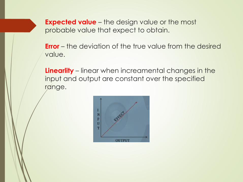
Expected value – the design value or the most
probable value that expect to obtain.
Error – the deviation of the true value from the desired
value.
Linearlity – linear when increamental changes in the
input and output are constant over the specified range.
Dynamic Variation
Characteristics
Step change - in which the primary element is subjected to an
instantaneous and finite change in measured variable.
Linear change - in which the primary element is following the
measured variable, changing linearly with time.
Sinusoidal change - in which the primary element follows a
measured variable, the magnitude of which changes in
accordance with a sinusoidal function of constant amplitude.

Dynamic Performance
Characteristics
The dynamic performance characteristics of an instrument
are:
Speed of response - The rapidity with which an instrument
responds changes in measured quantity.
Dynamic error -The difference between the true and
measured value with no static error.
Lag – delay in the response of an instrument to changes in the
measured variable.
Fidelity – the degree to which an instrument indicates the
changes in the measured variable without dynamic error
(faithful reproduction).
STANDARD
A standard is a known accurate measure of physical quantity.
Standards are used to determine the values of other physical quantities by the comparison method.
All standards are preserved at the International Bureau of Weight and Measures (BIMP), Paris.
Four categories of standard:
1) International Standard
2) Primary Standard
3) Secondary Standard
4) Working Standard

1) International Standard
Defined by International Agreement
Represent the closest possible accuracy attainable by the current science and technology
2) Primary Standard
Maintained at the National Standard Lab (different for every country)
Function: the calibration and verification of secondary Standard
Each lab has its own secondary Standard which are periodically checked and certified by the National Standard Lab.
For example, in Malaysia, this function is carried out by SIRIM.
3) Secondary Standard
Secondary standards are basic reference standards used by measurement and calibration laboratories in industries.
Each industry has its own secondary standard.
Each laboratory periodically sends its secondary standard to the National standards laboratory for calibration and comparison against the primary standard.
After comparison and calibration, the National Standards Laboratory returns the secondary standards to particular industrial laboratory with a certification of measuring accuracy in terms of a primary standard.
4) Working Standard
Used to check and calibrate lab instrument for accuracy and performance.
For example, manufacturers of electronic components such as capacitors, resistors and many more use a standard called a working standard for checking the component values being manufactured.

STANDARD OF MEASUREMENT

SI UNIT
SI meas International System Unit and mandated by ISO. These SI units are:
ERROR IN MEASUREMENT
Measurement Errors
Errors are always introduced when using instruments to
measure electrical quantities.
The errors most likely to occur in measurements are those due
to:
i) The limitations of the instrument;
ii) The operator;
iii) The instrument disturbing the circuit.
Errors in the limitations of the instrument
The calibration accuracy of an instrument depends on theprecision with which it is constructed.
Every instrument has a margin of error which is expressed as apercentage of the instruments full scale deflection (fsd).
For example industrial grade instruments have an accuracy of±2% of fsd. Thus if a voltmeter has a fsd of 100V and it indicates40V say, then the actual voltage may be anywhere between40±(2% of 100), or 40 ± 2, i.e. between 38V and 42 V.
When an instrument is calibrated, it is compared against astandard instrument.

Errors by the operator
It is easy for an operator to misread an instrument.
With linear scales the values of the sub-divisions are reasonably
easy to determine; non-linear scale graduations are more
difficult to estimate.
Also, scales differ from instrument to instrument and some meters
have more than one scale (as with multi-meters) and mistakes in
reading indications are easily made.
When reading a meter scale it should be viewed from an angle
perpendicular to the surface of the scale at the location of the
pointer; a meter scale should not be viewed ‘at an angle’.
Errors due to the instrument
disturbing the circuit
Any instrument connected into a circuit will affect that circuit to
some extent.
Meters require some power to operate, but provided this power
is small compared with the power in the measured circuit, then
little error will result.
Incorrect positioning of instruments in a circuit can be a source
of errors.
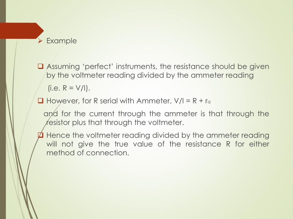
Example
Assuming ‘perfect’ instruments, the resistance should be given
by the voltmeter reading divided by the ammeter reading
(i.e. R = V/I).
However, for R serial with Ammeter, V/I = R + ra
and for the current through the ammeter is that through the
resistor plus that through the voltmeter.
Hence the voltmeter reading divided by the ammeter reading
will not give the true value of the resistance R for either
method of connection.
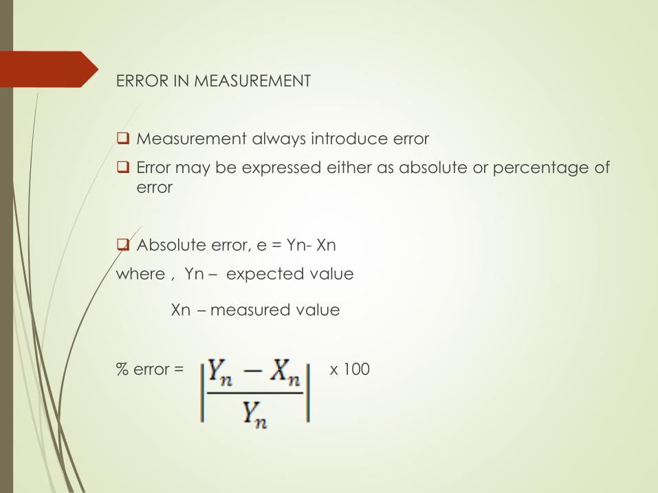
ERROR IN MEASUREMENT
Measurement always introduce error
Error may be expressed either as absolute or percentage of
error
Absolute error, e = Yn- Xn
where , Yn – expected value
Xn – measured value
% error = x 100

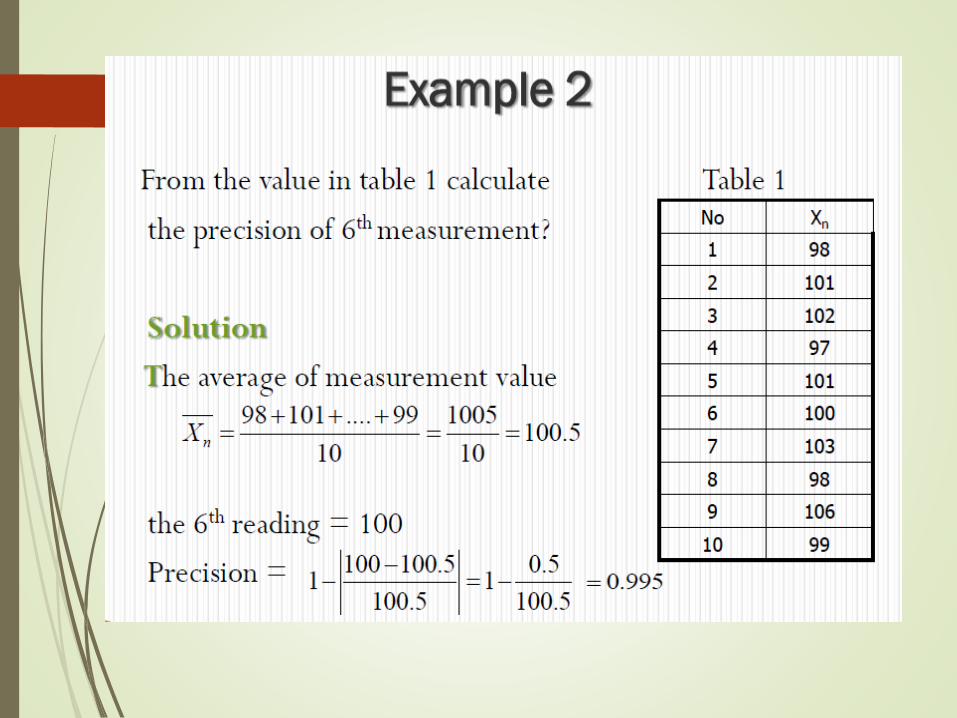
The precision of a measurement is a quantitative or numerical
indication of the closeness with which a repeated set of
measurement of the same variable agree with the average set of
measurements.

Example 1
Given expected voltage value across a resistor is 80V. The
measurement is 79V. Calculate,
i.The absolute error
ii.The % of error
iii.The relative accuracy
iv.The % of accuracy


LIMITING ERROR
The accuracy of measuring instrument is guaranteed within a certain percentage (%) of full scale reading
E.g manufacturer may specify the instrument to be accurate at ±2 % with full scale deflection
For reading less than full scale, the limiting error increases
Cont’d…
Example
Given a 600 V voltmeter with accuracy ±2% full scale.
Calculate limiting error when the instrument is used to measure a voltage of 250V?
Solution
The magnitude of limiting error, 0.02 x 600 = 12V
Therefore, the limiting error for 250V = 12/250 x 100 = 4.8%

Cont’d…
Example
Given for certain measurement, a limiting error for voltmeter at
70V is 2.143% and a limiting error for ammeter at 80mA is
2.813%. Determine the limiting error of the power.
Solution
The limiting error for the power
= 2.143% + 2.813%
= 4.956%

Exercise
A voltmeter is accurate 98% of its full scale reading.
i.If the voltmeter reads 200V on 500V range, what is the absolute
error?
ii.What is the percentage error of the reading in (i).

Rules regarding significant figures in calculation
1)For adding and subtraction, all figures in columns to the right of the last column in which all figures are significant should be dropped
Example
V1 = 6.31 V
+ V2 = 8.736 V
Therefore, VT = 15.046 V≈ 15.05 V

2)For multiplication and division, retain only as many significant figures as the least precise quantity contains
Example
From the value given below, calculate the value for R1, R2 and power for R1?
I = 0.0148 A ===> 3 s.f
V1 = 6.31 V ===> 3 s.f
V2 = 8.736 V ===> 4 s.f
3)When dropping non-significant figures
0.0148 ==> 0.015 (2 s.f)
==> 0.01 (1 s.f)


TYPES OF STATIC ERROR
Types of static error
1)Gross error/human error
2)Systematic Error
3)Random Error

1. Gross Error
Cause by human mistakes in reading/using instruments
may also occur due to incorrect adjustment of the instrument and the computational mistakes
cannot be treated mathematically
cannot eliminate but can minimize
eg: Improper use of an instrument.
This error can be minimized by taking proper care in reading and recording measurement parameter.
Therefore, several readings (at three readings) must be taken to minimize the effect of ambient condition changes.

2. Systematic Error
due to shortcomings of the instrument (such as defective or
worn parts, ageing or effects of the environment on the
instrument)
In general, systematic errors can be subdivided into static and
dynamic errors.
Static – caused by limitations of the measuring device or the
physical laws governing its behavior.
Dynamic – caused by the instrument not
responding very fast enough to follow the
changes in a measured variable.
Systematic Error classified into three categories :-
Three (3) types of systematic error :-
(i) Instrumental error
(ii) Environmental error
(iii) Observational error
(i) Instrumental Error (cont…)
a) Due to inherent shortcoming in the
instrument.
(eg: If the spring used permanent magnet
instrument has become weak the instrument
always read high. Error may caused because of
friction, hysterisisi, stretching of spring, etc)
b) Due to misuse of the instruments.
c) Due to loading effect of instruments.
error can be avoid by:
(i) selecting a suitable instrument for the
particular measurement application
(ii) calibrate the instrument against standard

(ii) Environmental Error (cont...)
due to external condition effecting the measurement
including surrounding area condition
These may be effect of temperature, dust, humidity, vibration
or electrostatic fields, etc
to avoid the error :-
(i) use air conditioner
(ii)sealing certain component in the instruments

(iii) Observational Error (cont…)
introduce by the observer
Inacurate estimate of average reading.
Wrong scale reading and wrong recording the data.
most common : parallax error and estimation error (while
reading the scale)
eg: an observer who tend to hold his head too far to the left
while reading the position of the needle on the scale.
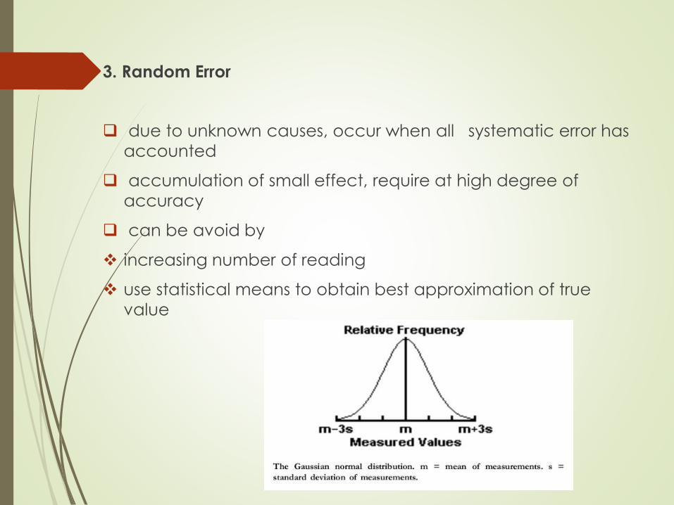
3. Random Error
due to unknown causes, occur when all systematic error has
accounted
accumulation of small effect, require at high degree of
accuracy
can be avoid by
increasing number of reading
use statistical means to obtain best approximation of true
value
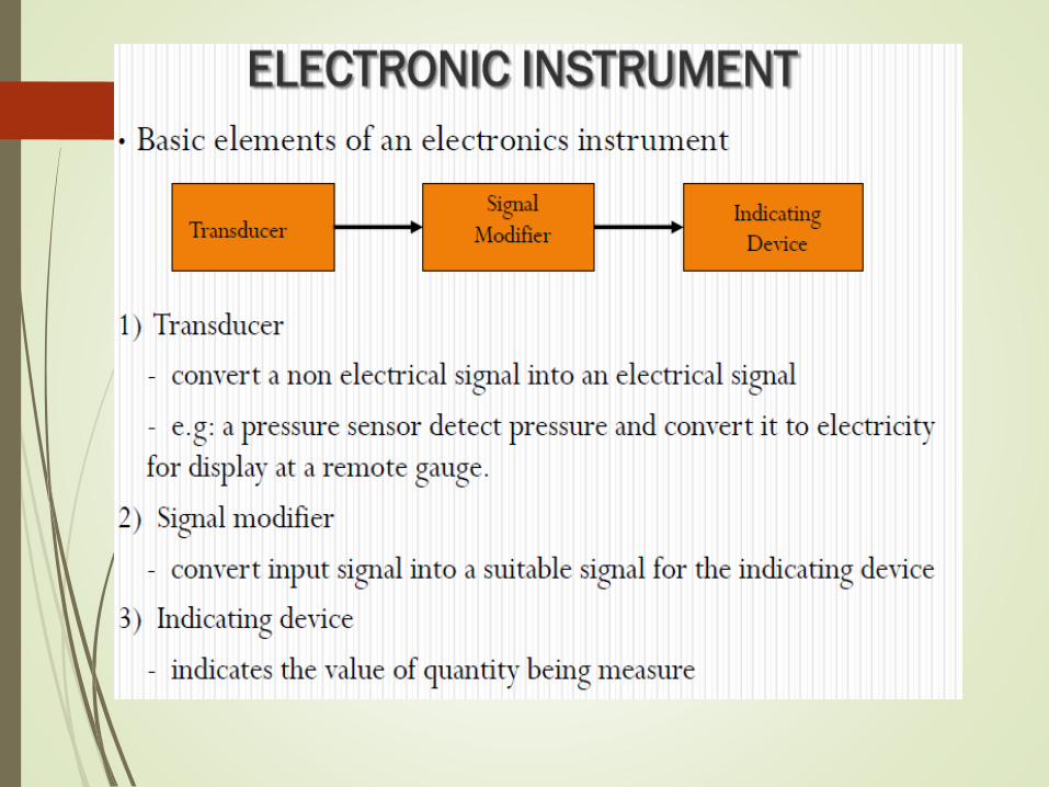

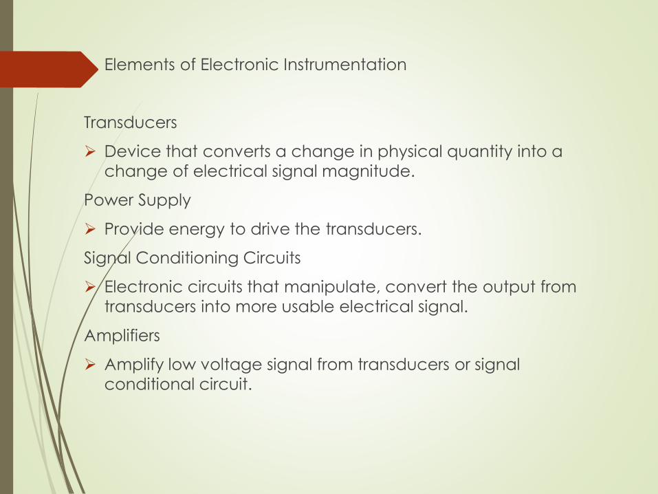
Elements of Electronic Instrumentation
Transducers
Device that converts a change in physical quantity into a
change of electrical signal magnitude.
Power Supply
Provide energy to drive the transducers.
Signal Conditioning Circuits
Electronic circuits that manipulate, convert the output from
transducers into more usable electrical signal.
Amplifiers
Amplify low voltage signal from transducers or signal
conditional circuit.

Cont’d…
Recorders
Used to display the measurement for easy reading and
interpretation.
Data Processors
Can be a microprocessor or microcontroller.
Process Controllers
Used to monitor and adjust any quantity of the specified level
or value.
Command Generator
Provide control voltage that represents the difference of the
parameter in a given process.

INSTRUMENT APPLICATION GUIDE
Selection, care and use of the instrument :-
Before using an instrument, students should be thoroughly familiar with its operation ** read the manual carefully
Select an instrument to provide the degree of accuracy
required (accuracy + resolution + cost)
Before used any selected instrument, do the inspection for any physical problem
Before connecting the instrument to the circuit, make
sure the ‘function switch’ and the ‘range selector switch’
has been set-up at the proper function or range