Embed Size (px)
Citation preview
Paper ID #23489
Measurement and Analysis of Carved Surfaces Made on a Self-Assembledand Tested Mini 3-Axis CNC Router
Dr. R. Radharamanan, Mercer University
Dr. R. Radharamanan is currently working as Professor of Industrial Engineering and Director of MercerCenter for Innovation and Entrepreneurship (MCIE) at Mercer University in Macon, Georgia. He hasforty four years of teaching, research, and consulting experiences. His previous administrative experi-ences include: President of International Society for Productivity Enhancement (ISPE), Acting Directorof Industrial Engineering as well as Director of Advanced Manufacturing Center at Marquette University,and Research Director of CAM and Robotics Center at San Diego State University. His primary researchand teaching interests are in the areas of manufacturing systems, additive manufacturing, rapid proto-typing, robotics and automation, innovation and entrepreneurship, quality engineering, and product andprocess development. He has organized and chaired five international conferences, co-chaired two, andorganized and chaired three regional conferences. He has received two teaching awards, several researchand service awards in the United States and in Brazil. His present and past professional affiliations includeASEE, IIE, ASQ, SME, ASME, and ISPE.
c©American Society for Engineering Education, 2018
Measurement and Analysis of Carved Surfaces Made on a
Self-Assembled and Tested Mini 3-Axis CNC Router
Abstract
Computer numerical control is a very broad term that encompasses a variety of types of
machines — all with different sizes, shapes, and functions. But the easiest way to think about
CNC is to simply understand that it is all about using a computer as a means to control a machine
that carves useful objects from solid blocks of material. Traditional CNC machines are
expensive, complicated, and typically only found in large manufacturing companies that can
afford them. Small hobbyist CNC machines can run anywhere from $7,000 and higher;
professional machines can cost millions of dollars! Now, for a fraction of the cost — under $800
one can own a Mini 3-axis CNC machine and cut, drill, mill, and carve objects of one's
imagination.
In this paper, a Mini 3-axis CNC router was assembled and tested. Simple shapes of circles and
squares were cut on two different materials: plastic and wood. Diameter of the circles and side of
squares were measured using a digital caliper. Data were collected for a 2k factorial design
experiments considering 2-levels for parameters: spindle speed, feed rate, cut depth, material,
and object shape. Statistical analyses using Minitab and/or Microsoft Excel were performed on
the collected data. Effects of chosen parameters on the dimensional accuracy of the parts made
were analyzed. The results indicated that cut depth, material, and object shape have significant
effects on the dimensional accuracy of the parts made. Through this hands-on project, the
students were trained in assembling and testing a CNC router, cutting simple to complex shapes
using G-Codes, measuring the parts made for dimensional accuracy, collecting data for
experimental design, and analyzing the data using Minitab and Microsoft Excel. Some of the
difficulties encountered in assembling and testing the CNC router and the learning experience
from the student team are also presented and discussed.
Introduction
Numerical control, popularly known as the NC is very commonly used in the machine tools.
Numerical control is defined as the form of programmable automation, in which the process is
controlled by the numbers, letters, and symbols. In case of the machine tools this programmable
automation is used for the operation of the machines. CNC is the short form for Computer
Numerical Control. The NC machine works as per the program of instructions fed into the
controller unit of the machine. The CNC machine comprises of the mini computer or the
microcomputer that acts as the controller unit of the machine. While in the NC machine the
program is fed into the punch cards, in CNC machines the program of instructions is fed directly
into the computer via a small board similar to the traditional keyboard. CNC machines were

originally built for machining metals. They were subsequently adapted for other industries such
as wood, fabric, foam, and plastics to name just a few. All these machines have some features in
common which are: a program (instructions), a controller, and a machine tool1, 2.
At present, machine tools can be automatically programmed with the help of artificial
intelligence. Based on a CAD-model of the product, the system, without any help from an expert,
automatically prepares a CNC program, so that the machine is safe, accurate and time efficient.
The developed system consists of a prediction and evaluation module as well as a simulation
model for searching optimal solutions3. Recently, a study was also made to optimize the process
parameters (cutting speed, feed rate, and depth of cut) for better surface roughness (SR) and
material removal rate (MRR) on different materials4.
CNC router is a computer-controlled cutting machine related to the hand held router used for
cutting various hard materials, such as wood, composites, aluminum, steel, plastics, and foams.
CNC routers can perform the tasks of many carpentry shop machines such as the panel saw,
the spindle molder, and the boring machine. A CNC router is very similar in concept to a
CNC milling machine. Instead of routing by hand, tool paths are controlled via computer
numerical control. The CNC router is one of many kinds of tools that have CNC variants.
A CNC router typically produces consistent and high-quality work and improves factory
productivity. Automation and precision are the key benefits of CNC router tables. A CNC router
can reduce waste, frequency of errors, and the time the finished product takes to get to market5.
This paper is one of the outcomes of the Mercer Summer Engineering Experience (MeSEE
2017), an Academic Training program, in which multidisciplinary student teams were trained in
engineering labs and then worked on hand-on projects over a period of 10 weeks (30-40 hours/
week) in the lab environment, during 2017 Summer semester to complete the chosen projects.
Three senior students (Abdullah Alfadel, Industrial Engineering; Kyle Trammell, Mechanical
Engineering; and Riley Atkinson, Industrial Management) forming a multidisciplinary team
worked on this project.
The overall objective of this project is to assemble/build and test a mini 3-axis CNC router in a
laboratory environment; and conduct experiments, collect, analyze, and interpret data within the
ten weeks duration of the academic training. This includes:
1. Provide training to the student team in CAD/CAM, and G-Code programming;
2. Review of literature and watching online tutorials related to DIY CNC router projects;
3. Assemble/build and test the mini 3-axis CNC router;
4. Provide training to operate the CNC router and carve simple/complex shapes on different
materials;
5. Collect data for a 2k factorial design experiment considering 2-levels of machining, material,
and shape parameters;
6. Measure the parts made of plastic and wood for dimensional accuracy and compare the
results;
7. Use Minitab and/or Excel to analyze the data collected;
8. Discuss the results based on statistical theory;
9. Write the final report with the team members and prepare the poster for final presentation in
consultation with the academic training advisor. Submit the final report and make the oral
and poster presentation.
In addition, this project is designed to fully/partially satisfy some of the ABET's student learning
outcomes (a-k) and/or proposed new outcomes (1-7) that include:
b. An ability to design and conduct experiments, as well as to analyze and interpret data (new
outcome 3);
c. An ability to design a system, component, or process to meet desired needs within realistic
constraints such as safety, manufacturability, and sustainability (new outcome 2);
d. An ability to function on multidisciplinary teams (new outcome 7);
g. An ability to communicate effectively (orally and written) - (new outcome 4);
k. An ability to use the techniques, skills, and modern engineering tools necessary for
engineering practice (new outcome 6).
In this project, the student team has built and tested a DIY CNC router for machining different
materials, plastic and wood. Simple shapes of circles (diameter, d = 1") and squares (side, a = 1")
were cut using the CNC router. G-Code programs were developed to cut the required circles and
squares. A digital caliper was used to measure the diameter of the circles and the side of the
squares. The measured data were used to perform statistical analyses using Minitab and/or
Microsoft Excel. Results obtained from statistical analyses were presented and discussed.
Background
CNC History
NC or simply Numerical Control was developed in the late 1940s and early 1950s by John T.
Parsons in collaboration with MIT (Massachusetts Institute of Technology). It was developed to
help in the post war manufacturing effort. Aircraft parts were becoming more complex and
required a level of precision that human operators could not achieve. At first machines were
hardwired, and then instructions were given via punched tape starting in 1952. Five years later,
NC machines were being installed in metal working production environments all over the United
States. By the mid 1960s, NC technology was playing a dominant role in the industry. Most
machine programs were recorded on a punched paper or aluminum tape until about 1980. The
growth of microprocessor technology in the 1970s and 1980s made it possible for computers to
be connected directly to NC machines using cables and hence the term CNC1, 2.
There are two main types of CNC machine tools and the control systems required for use
with them differ because of the basic differences in the functions of the machines to be
controlled. They are known as point-to-point and contouring controls. Some machine tools for
example drilling, boring and tapping machines etc., require the cutter and the work piece to be
placed at a certain fixed relative positions at which they must remain while the cutter does its
work. These machines are known as point-to-point machines. Other type of machine tools
involves motion of work piece with respect to the cutter while cutting operation is taking place.
These machine tools include milling, routing machines etc., and are known as contouring

machines. A milling machine is a machine that has a spindle (a device similar to a router) with a
special tool that spins and cuts in various directions and moves in three different directions along
the x, y, and z axes6, 7.
A DIY Desktop CNC Machine is a “personal” version of a CNC machine. It is controlled by a
desktop computer and is designed for the hobbyist or enthusiast to create objects within a
relatively compact space and at modest expense. To that end, the DIY Desktop CNC Machine is
designed to provide a resolution of one thousandth of an inch (0.001”) per step in each axis, and
was intended to be accessible and buildable by the average DIY'er with non-specialist domestic
tools8-11.
A small CNC router (work area: 20 cm x 20 cm) was installed and tested in a small scale
industry in Indonesia for cutting, engraving, and marking on wood, acrylic and PCB objects.
When tested, this router was able to provide 98.5% of carving accuracy and 100% of depth
accuracy9.
An automatic mini CNC machine for PCB drawing and drilling based on low cost CNC system
was designed and made by incorporating features of PC with ATMEGA 328 controller in an
arduino12. A low cost CNC router was designed and fabricated to fulfill the demand of CNC
routers from small scale to large scale industries with optimized low cost13. A mini CNC router
which is compatible to extrude as 3D printer, less expensive and affordable, compact in size and
less power consuming and user friendly interface to operate very smoothly was designed and
fabricated14.
Effect of machining parameters such as speed, feed, and depth of cut on surface finish on a CNC
router were analyzed using Taguchi's robust design approach using orthogonal arrays and
analysis of variance models. The results indicated that feed rate has the highest influence on
surface finish followed by spindle speed and depth of cut15.
Materials and Methods
DIY CNC Machine
DIY CNC Router Kit used in this project is a mini CNC for study and research. It requires self-
assembling and certain mechanical skills to assemble. According to the product details "The
machine can carve wood, plastic, acrylic, PCB CCL, soft metals like copper and aluminum and
other materials: working area: 240 * 170 * 65 mm; positioning accuracy: 0.04 mm; and software:
easy to use GRBL"8. Figure 1 shows the components of the DIY CNC Router Kit.
Measuring Device
In this project, a digital caliper was used to measure the diameter of the circles and the side of the
squares (Fig. 2). A caliper is a device used to measure the distance between two opposite sides of
an object. It has a rated accuracy of 0.001 inches16.

Figure 1: Components of DIY CNC Router Kit
Figure 2: Digital Caliper
G-Codes for Cutting Circles and Squares17
The G-Codes for cutting circles and squares are given in Table 1.
Table 1: G-Codes for Circles and Squares Circle Square
G20 M3 S1000
G90
G00 X0 Y0 Z0
G01 Z-___ F__
G02 X0 Y0 I.446 J0 F__
G00 X0 Y0
G01 Z-___ F__
G02 X0 Y0 I.446 J0 F__
M30
G28
G20 G90 G40
G0 M3 S____
Z-_____
G1 X.918 F__
G1 Y.918
G1 X0
G1 Y0
M30
G28
Two levels of spindle speed (S), feed rate (F), and depth of cut (Z) were used to cut two simple
shapes, circles and squares, on two different materials, plastic and wood.
The Electronics of the CNC
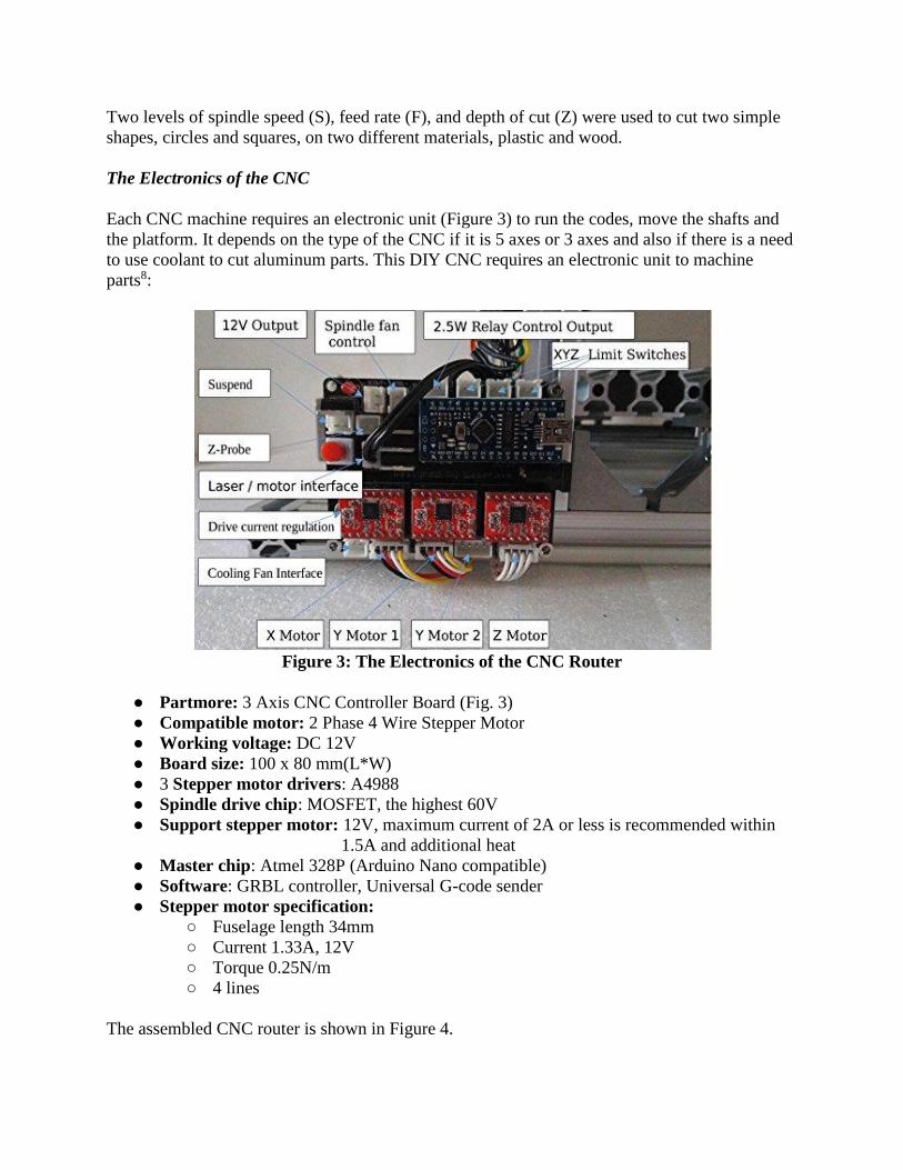
Each CNC machine requires an electronic unit (Figure 3) to run the codes, move the shafts and
the platform. It depends on the type of the CNC if it is 5 axes or 3 axes and also if there is a need
to use coolant to cut aluminum parts. This DIY CNC requires an electronic unit to machine
parts8:
Figure 3: The Electronics of the CNC Router
● Partmore: 3 Axis CNC Controller Board (Fig. 3)
● Compatible motor: 2 Phase 4 Wire Stepper Motor
● Working voltage: DC 12V
● Board size: 100 x 80 mm(L*W)
● 3 Stepper motor drivers: A4988
● Spindle drive chip: MOSFET, the highest 60V
● Support stepper motor: 12V, maximum current of 2A or less is recommended within
1.5A and additional heat
● Master chip: Atmel 328P (Arduino Nano compatible)
● Software: GRBL controller, Universal G-code sender
● Stepper motor specification:
○ Fuselage length 34mm
○ Current 1.33A, 12V
○ Torque 0.25N/m
○ 4 lines
The assembled CNC router is shown in Figure 4.
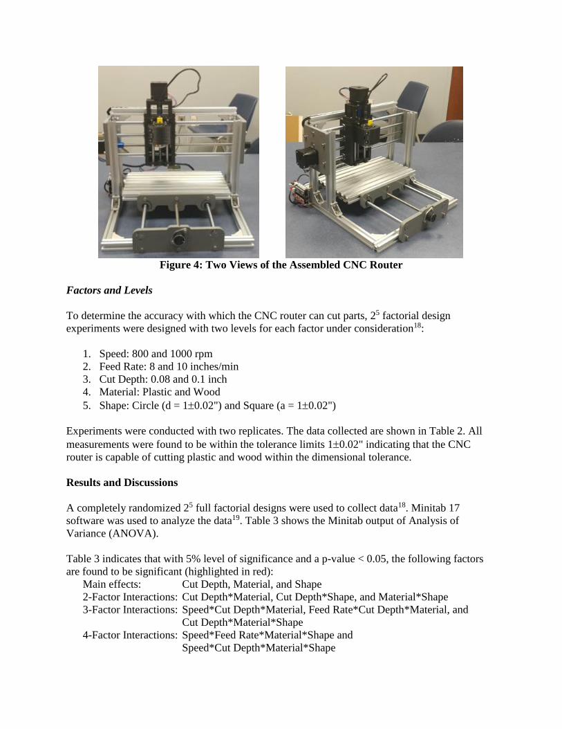
Figure 4: Two Views of the Assembled CNC Router
Factors and Levels
To determine the accuracy with which the CNC router can cut parts, 25 factorial design
experiments were designed with two levels for each factor under consideration18:
1. Speed: 800 and 1000 rpm
2. Feed Rate: 8 and 10 inches/min
3. Cut Depth: 0.08 and 0.1 inch
4. Material: Plastic and Wood
5. Shape: Circle (d = 10.02") and Square (a = 10.02")
Experiments were conducted with two replicates. The data collected are shown in Table 2. All
measurements were found to be within the tolerance limits 10.02" indicating that the CNC
router is capable of cutting plastic and wood within the dimensional tolerance.
Results and Discussions
A completely randomized 25 full factorial designs were used to collect data18. Minitab 17
software was used to analyze the data19. Table 3 shows the Minitab output of Analysis of
Variance (ANOVA).
Table 3 indicates that with 5% level of significance and a p-value < 0.05, the following factors
are found to be significant (highlighted in red):
Main effects: Cut Depth, Material, and Shape
2-Factor Interactions: Cut Depth*Material, Cut Depth*Shape, and Material*Shape
3-Factor Interactions: Speed*Cut Depth*Material, Feed Rate*Cut Depth*Material, and
Cut Depth*Material*Shape
4-Factor Interactions: Speed*Feed Rate*Material*Shape and
Speed*Cut Depth*Material*Shape
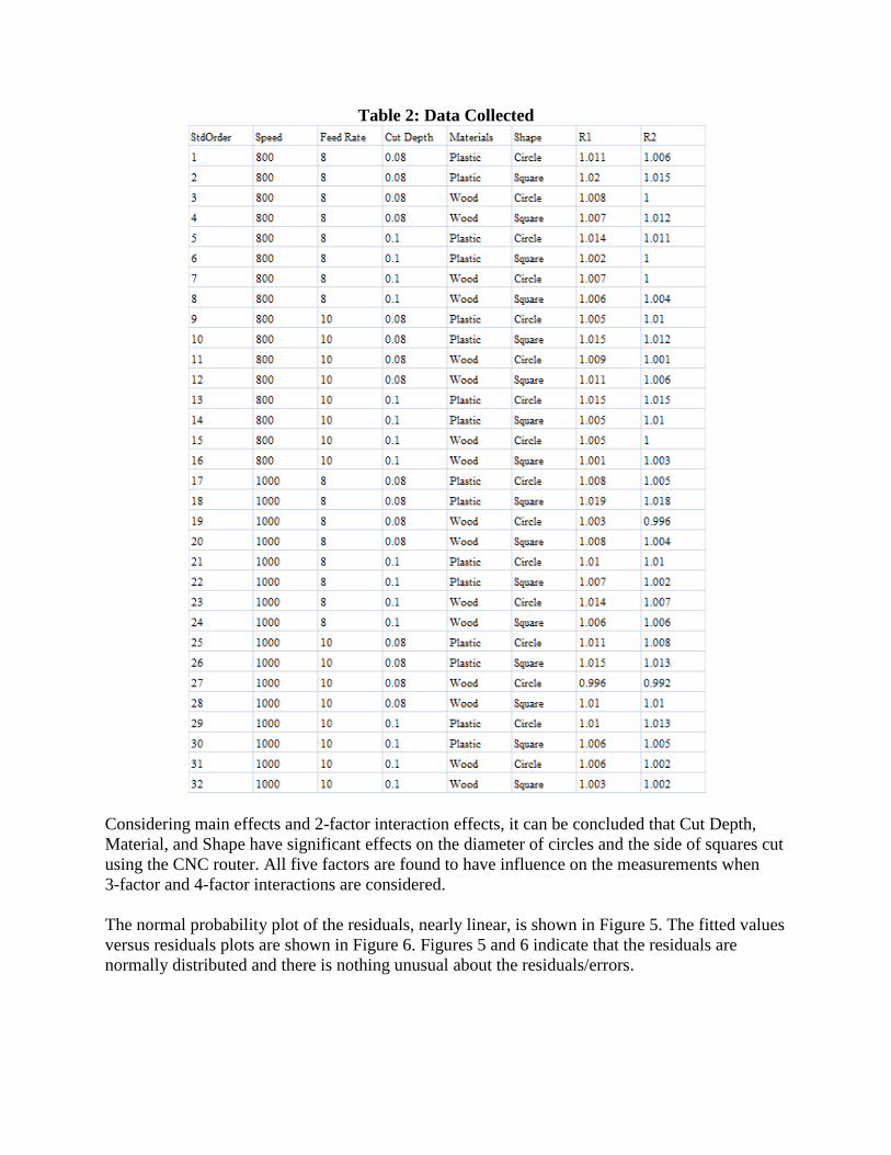
Table 2: Data Collected
Considering main effects and 2-factor interaction effects, it can be concluded that Cut Depth,
Material, and Shape have significant effects on the diameter of circles and the side of squares cut
using the CNC router. All five factors are found to have influence on the measurements when
3-factor and 4-factor interactions are considered.
The normal probability plot of the residuals, nearly linear, is shown in Figure 5. The fitted values
versus residuals plots are shown in Figure 6. Figures 5 and 6 indicate that the residuals are
normally distributed and there is nothing unusual about the residuals/errors.
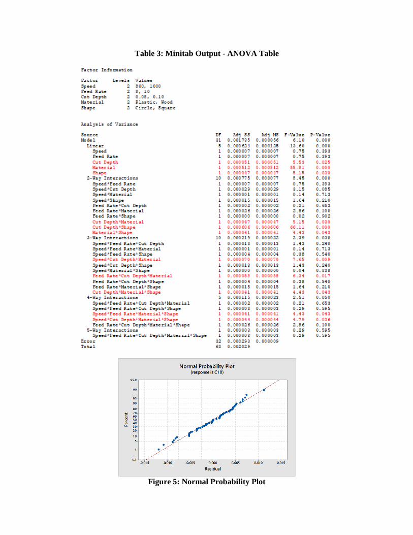
Table 3: Minitab Output - ANOVA Table
Figure 5: Normal Probability Plot
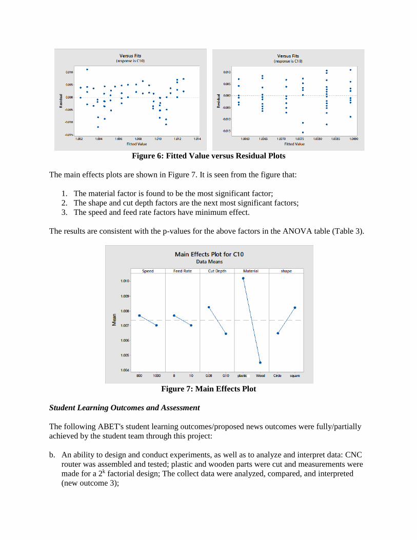
Figure 6: Fitted Value versus Residual Plots
The main effects plots are shown in Figure 7. It is seen from the figure that:
1. The material factor is found to be the most significant factor;
2. The shape and cut depth factors are the next most significant factors;
3. The speed and feed rate factors have minimum effect.
The results are consistent with the p-values for the above factors in the ANOVA table (Table 3).
Figure 7: Main Effects Plot
Student Learning Outcomes and Assessment
The following ABET's student learning outcomes/proposed news outcomes were fully/partially
achieved by the student team through this project:
b. An ability to design and conduct experiments, as well as to analyze and interpret data: CNC
router was assembled and tested; plastic and wooden parts were cut and measurements were
made for a 2k factorial design; The collect data were analyzed, compared, and interpreted
(new outcome 3);
c. An ability to design a system, component, or process to meet desired needs within realistic
constraints such as safety, manufacturability, and sustainability: CNC router was assembled
and tested for functionality and measurements were made for different machining parameters
(new outcome 2);
d. An ability to function on multidisciplinary teams: The student team was multidisciplinary
(industrial, mechanical, and industrial management students) and they were able to work
together in the lab environment and also achieve the overall objective of this project within
the 10 weeks period (new outcome 7);
g. An ability to communicate effectively (orally and written): The student team submitted the
written report and the poster; they made the oral and poster presentation at the end of the
academic training period (new outcome 4);
k. An ability to use the techniques, skills, and modern engineering tools necessary for
engineering practice: The student team used the techniques, skills, and engineering tools they
learnt and practiced to successfully complete this hands-on project within the period of 10
weeks (new outcome 6).
Assessment made on this project by student peers and the faculty members indicated that the
student team fulfilled their initial goals and objectives and this project was rated as one of the
best projects done by the student teams under Mercer Summer Engineering Experience (MeSEE
2017) Academic Training program with an average score greater than 4 in the 5-level Likert
scale in all five ABET's student learning outcomes (b, c, d, g, and k; corresponding new
outcomes 3, 2, 7, 4, and 6 respectively) considered for this project.
Conclusions and Recommendations
The DIY CNC router assembled and tested by the student team is capable of cutting materials
(plastic and wood) within the dimensional tolerances (10.02"). The Minitab output shows that
the normal probability plot is nearly linear indicating that the residuals/errors are normally
distributed and there is nothing unusual about the residuals. Main effects and the 2-factor
interaction effects indicate that cut depth, material, and shape have significant effects on the
measured values. All five factors showed significant effects at higher order interactions (3-factor
and 4-factor interactions). The main effect plots show that the material has the highest effects on
the machining, as it was expected because the materials used, plastic and wood, have different
levels of softness.
Through this hands-on project, the student team was trained in assembling and testing a CNC
router, cutting simple to complex shapes using G-Codes, measuring the parts made for
dimensional accuracy, collecting data for experimental design, and analyzing the data using
Minitab and Microsoft Excel. This is an excellent hand-on learning experience for the student
team.
Using the DIY CNC router, other materials such as wax, acrylic, soft metals like copper and
aluminum can be cut and tested for dimensional accuracy. The CNC router assembled and tested
by the student team is now available for other students for further studies.
Assessment made by student peers and the faculty members indicated that the student team on
average scored greater than 4 in the 5-level Likert scale in all five ABET's student learning
outcomes (b, c, d, g, and k; corresponding new outcomes 3, 2, 7, 4, and 6 respectively)
considered for this project.
Challenges and Lessons Learned
Several problems arose during the process, like delay in the arrival of CNC router kit, assembly
errors, inappropriate clamps for holding the work material, 3D printed plastic brittle components,
among others. Excluding unforeseen problems mentioned above, there were the challenges of
interfacing laptop with the CNC router and writing proper G-code programming. These problems
were solved referring to resources such as internet, reference manuals, and books as well as
watching online tutorials and reading related articles. Focus and dedication of the student team
was the key to successfully complete the project and make the CNC router working.
Recommendations
The student team worked on this project has the following recommendations with respect to the
DIY CNC router kit: More practical clamps for holding the material on the table are required.
The supplied clamps often slid off the work materials. There were a few ways that the team
thought to remedy this. One was to add more surface area to the contact points. Another was to
include more practical and sturdy faceplate attachments for the clamps. The team also had one
problem while assembling the kit: 3D printed plastic components of the kit were brittle. They
would fracture and break off at times.
As recommendation for anyone who wants to build their own CNC router the following
suggestions are made: Take proper training in CAD/CAM and operating CNC machines; conduct
background research on CNC machines and DIY CNC routers; read carefully the related
materials (reference manuals, books, articles, internet resources, etc.) and watch online tutorials;
and take proper safety measures while running the CNC router.
Acknowledgment
This project was funded by the Mercer Summer Engineering Experience (MeSEE) program of
Mercer University School of Engineering during the Summer Semester of 2017.
References
[1] T. C. Chang, R. A. Wysk and H. P. Wang, Computer-Aided Manufacturing, Third Edition, Prentice Hall,
2006.
[2] Mikell P. Groover, Automation, Production Systems, and Computer-Integrated Manufacturing, Pearson
Education, 2015.
[3] S. Klancnik, M. Brezicnik, and J. Balie, Intelligent CAD/CAM Systems for Programming of CNC Machine
Tools, Int. J. of Simulation Models, 15 (2016) 1, 109-120.
[4] V. D. Patil, S. Sali, and D. J. Shinde, Optimization of Process Parameters for Machining Different Materails
on CNC Machine-Review, Int. J. Innovation and Engineering Research and Technologies (IJIERT). Vol. 2,
Issue 1, Jan. 2016, pp. 1-4.
[5] A. Albert, Understanding CNC Routers, FPI Innovations - Forintek Division, First Edition, Retrieved July 15,
2017, www.fpinnovations.ca.
[6] P. Hood-Daniel and J.F. Kelly, Build Your Own CNC Machine, Apress, 2009.
[7] T. Spilling, Self-Improving CNC Milling Machine, Master's Thesis, Department of Physics, University of
Oslo, 2014.
[8] DIY CNC Router Kit, Retrieved, May 12, 2017, https://www.amazon.com/24x17cm-Milling-Machine-
Desktop-Engraving/dp/B01NBTLIM8.
[9] R. Ginting, S. Hadiyoso, and S. Aulia, Implementation of 3-Axis CNC Router for Small Scale Industry. Int. J.
Applied Engineering Research, Vol. 12, No. 17 (2017), pp. 6553-6558.
[10] DIY Desktop CNC Machine Plans and Comprehensive Builder's Manual, 2011, Retrieved July 15, 2017,
www.MyDIYCNC.com.
[11] D. B. Patel and A. R. Kyada, DIY CNC: A Review, Proc. 5th Int. & 26th All India Manufacturing
Technology, Design and Research Conference, December 12-14, 2014, IIT Guwahati, Assam, India, pp.587-1
to 587-5.
[12] K. J. Mudekar et al, Automatic Mini CNC Machine for PCB Drawing and Drilling, Int. Research Journal of
Engineering and Technology (IRJET), Vol. 3, Issue 2, pp. 1106-1110, Feb. 2016.
[13] B. Jayachandraiah et al, Fabrication of Low Cost 3-Axis CNC Router, International Journal of Engineering
Science Invention, Vol. 3, Issue 6, June 2014, pp.1-10.
[14] D. Dey, S. Mondal, and A. K. Barik, 3-Axis CNC Router Modifiable to 3D Printer, Int. J. Innovation
Research in Science, Engineering, and Technology, Vol. 5, Issue 9, pp. 16983-16990, Sep. 2016.
[15] D. H. Patel and V. N. Patni, An Investigation Effect of Machining Parameters on CNC Router, Int. J.
Engineering Development and Research, Vol. 2, Issue 2, 2014, pp. 1583-1587.
[16] Digital Calipers: Retrieved June 10, 2017, https://www.amazon.com/digital-calipers/b?node=2476630011.
[17] F. Nanfara, T. Uccello, and D. Murphy, The CNC Workshop: A Multimedia Introduction to Computer
Numerical Control, Addison Wesley Longman, Inc. 1999.
[18] D. C. Montgomery, Design and Analysis of Experiments, 9th Edition, John Wiley, 2017.
[19] Minitab 17: Minitab Statistical Software Package, June 2017, http://www.minitab.com/enus/products/
minitab/.