Embed Size (px)
Citation preview
M.Czapkiewicz
Department of Electronics, AGH University of Science and Technology, POLAND
Calculations of interplay between anizotropy and
coupling energy in magnetic multilayers systems
• Schedule • one-domain S-W model• MAGEN2 - program for simulation of magnetization process of multilayers systems• examples of calculations and experiments
– PSV– SV– Biased FP– TMR SV – SV AAF
• To-do tasks
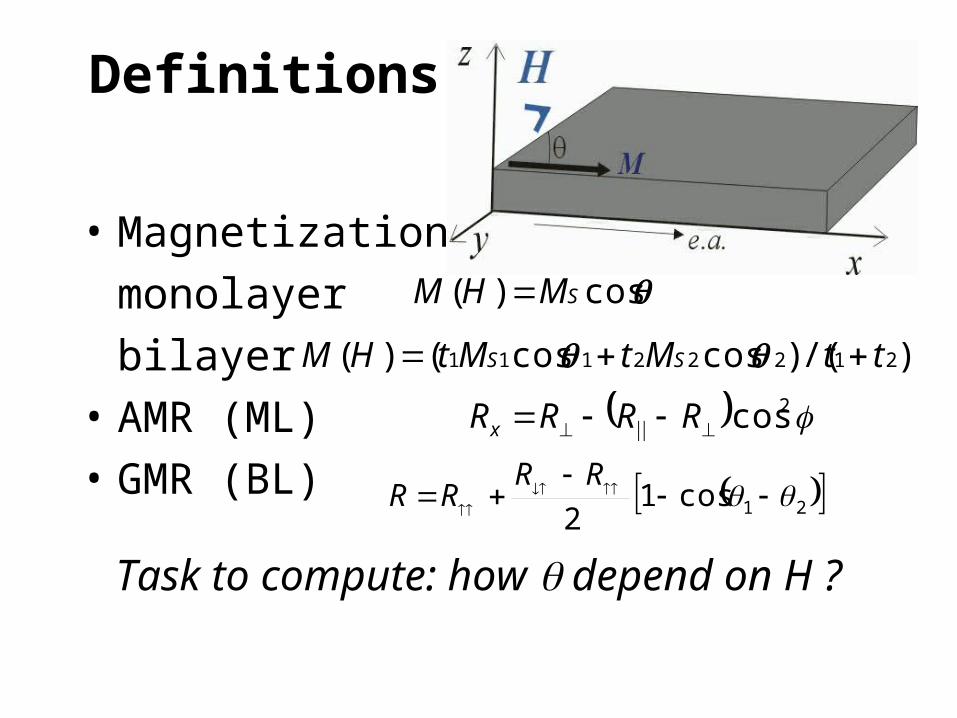
Definitions
• Magnetization:
monolayer
bilayer
• AMR (ML)
• GMR (BL)
Task to compute: how depend on H ?
cos)( SMHM
)/()coscos()( 21222111 ttMtMtHM SS
2cos RRRRx
21cos12
RRRR
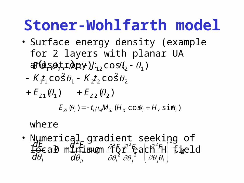
Stoner-Wohlfarth model• Surface energy density (example for 2 layers with
planar UA anisotropy):
where• Numerical gradient seeking of local minimum for
each H field
,..., 21 E )cos( 1212 J
)(
cos
11
12
11
ZE
tK
)(
cos
22
22
22
ZE
tK
0id
dE
0
2
iid
Ed
0
22
2
2
2
2
ijji
EEE
)sincos()( 0 iYiXSiiiZi HHMtE
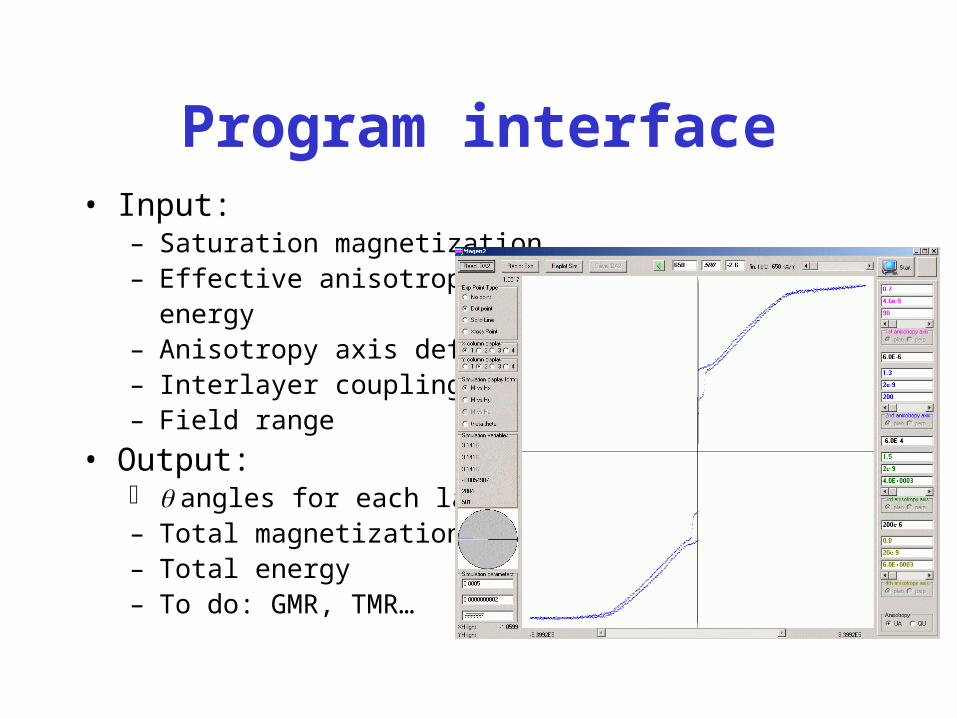
Program interface• Input:
– Saturation magnetization– Effective anisotropy
energy– Anisotropy axis definition– Interlayer coupling energy– Field range
• Output: angles for each layer– Total magnetization M(H)– Total energy– To do: GMR, TMR…
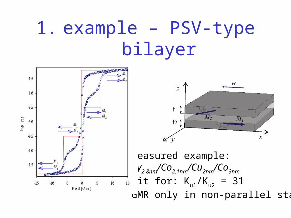
1. example – PSV-type bilayer
Measured example:Py2.8nm/Co2.1nm/Cu2nm/Co3nm
Fit for: Ku1/Ku2 = 31
GMR only in non-parallel state
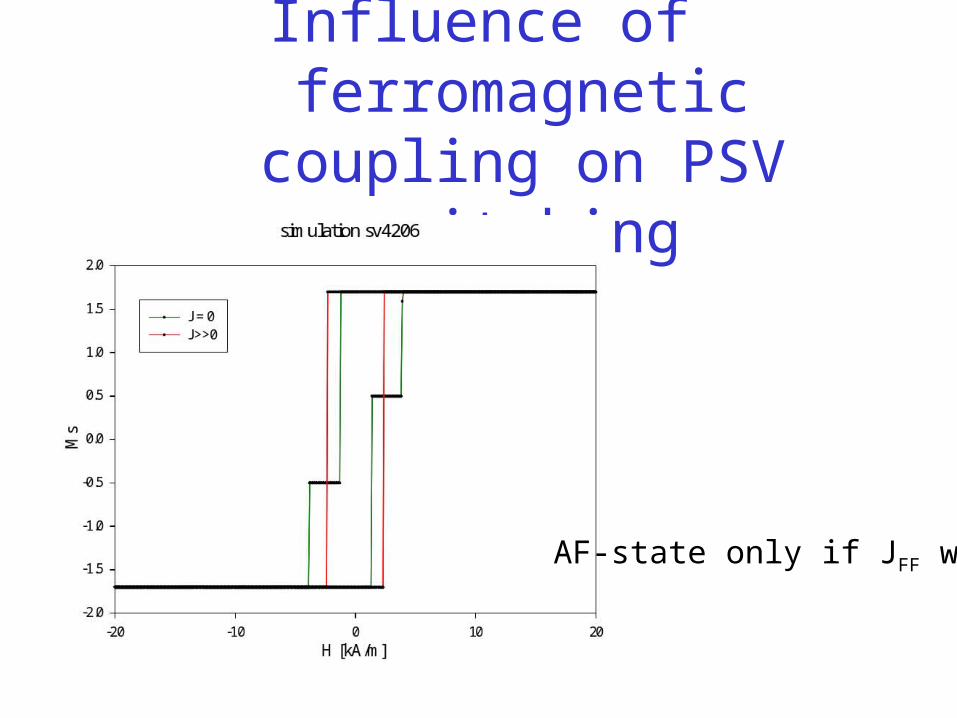
Influence of ferromagnetic coupling on PSV switching
AF-state only if JFF weak
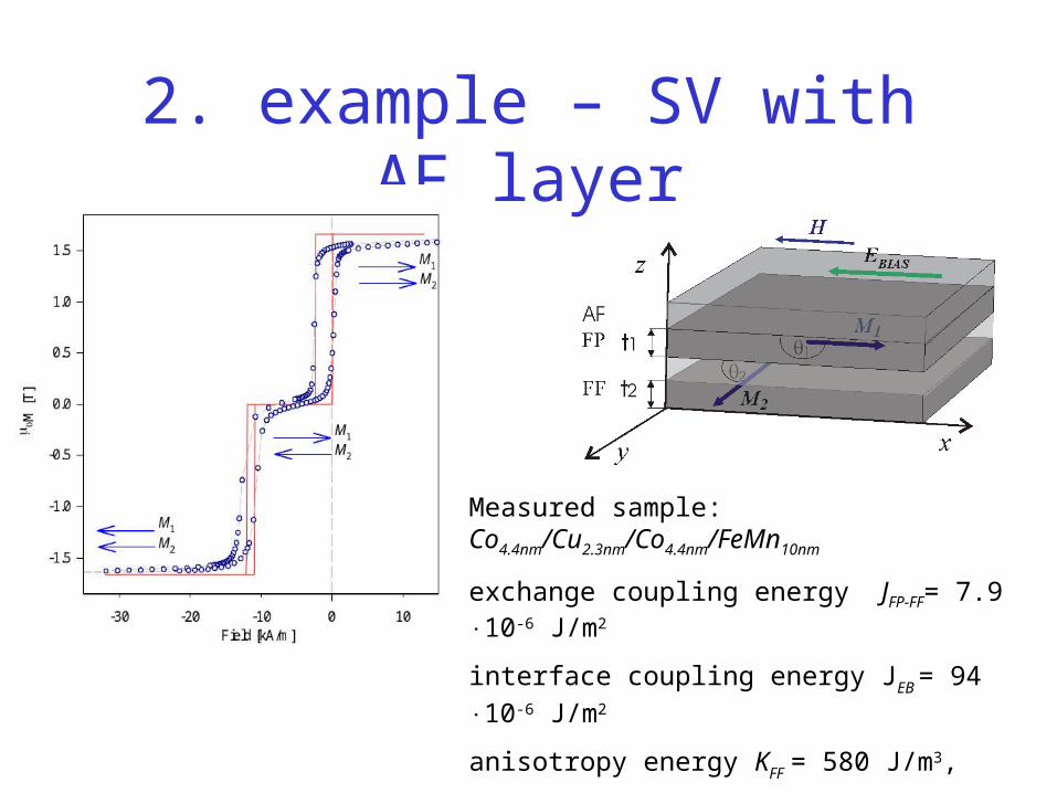
2. example – SV with AF layer
Measured sample: Co4.4nm/Cu2.3nm/Co4.4nm/FeMn10nm
exchange coupling energy JFP-FF= 7.9 10-6 J/m2
interface coupling energy JEB = 94 10-6 J/m2
anisotropy energy KFF = 580 J/m3,
effective AF anizotropy KAF = 80·103 J/m3
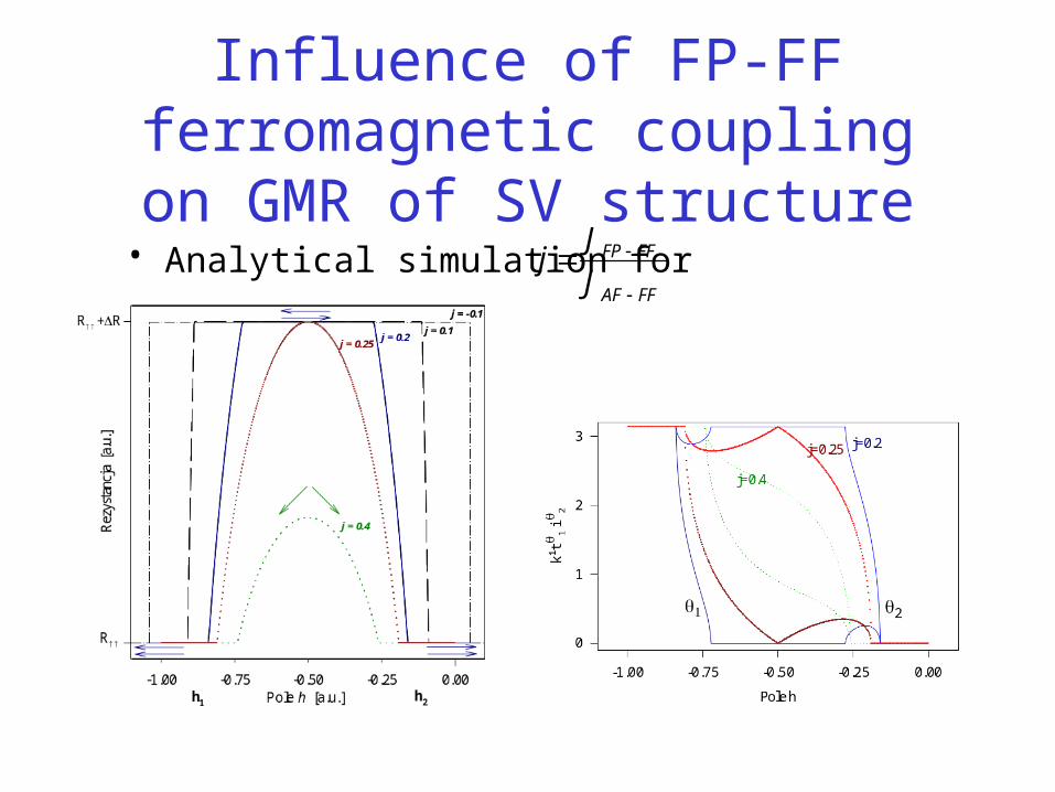
Influence of FP-FF ferromagnetic coupling on GMR of SV structure• Analytical simulation for
FFAF
FFFP
J
Jj
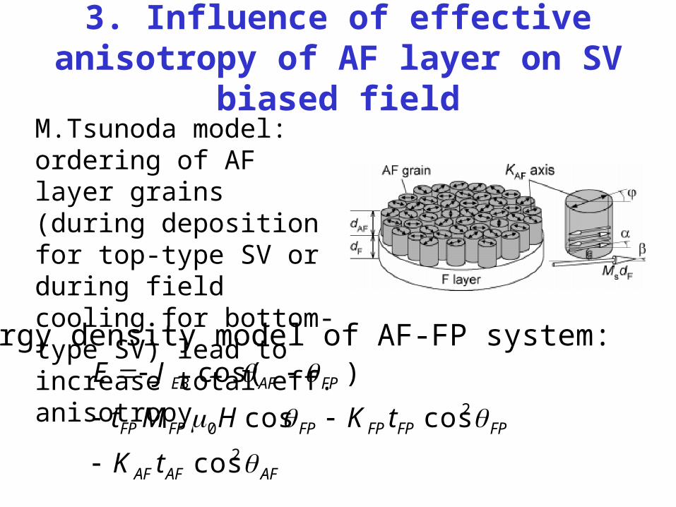
3. Influence of effective anisotropy of AF layer on SV biased field
Energy density model of AF-FP system:
2
20
cos
coscos
)cos(
AFAFAF
FPFPFPFPFPFP
FPAFEB
tK
tKHMt
JE
M.Tsunoda model: ordering of AF layer grains (during deposition for top-type SV or during field cooling for bottom-type SV) lead to increase total eff. anisotropy
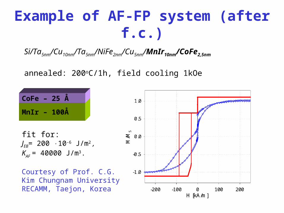
Example of AF-FP system (after f.c.)
Courtesy of Prof. C.G. Kim Chungnam University RECAMM, Taejon, Korea
MnIr – 100Å
CoFe – 25 Å
Si/Ta5nm/Cu10nm/Ta5nm/NiFe2nm/Cu5nm/MnIr10nm/CoFe2,5nm
annealed: 200oC/1h, field cooling 1kOe
fit for: JEB= 200 10-6 J/m2 , KAF = 40000 J/m3.
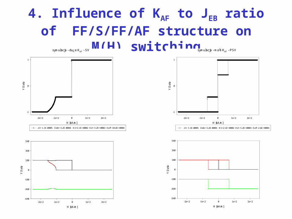
4. Influence of KAF to JEB ratio of FF/S/FF/AF structure on M(H) switching
symulacja - ma³e KAF - PSV
H [kA/m]
-2e+2 -1e+2 0 1e+2 2e+2
Y D
ata
-1
0
1
J1= 1.1E-0005 Eeb= 5.2E-0004 K1=2.1E+0002 K2= 5.2E+0003 Kaf= 2.6E+0004
H [kA/m]
-2e+2 -1e+2 0 1e+2 2e+2
Y D
ata
-540
-360
-180
0
180
360
540
symulacja - du¿e KAF - SV
H [kA/m]
-2e+2 -1e+2 0 1e+2 2e+2
Y D
ata
-1
0
1
J1= 1.1E-0005 Eeb= 5.2E-0004 K1=2.1E+0002 K2= 5.2E+0003 Kaf= 10.4E+0004
H [kA/m]
-2e+2 -1e+2 0 1e+2 2e+2
Y D
ata
-540
-360
-180
0
180
360
540
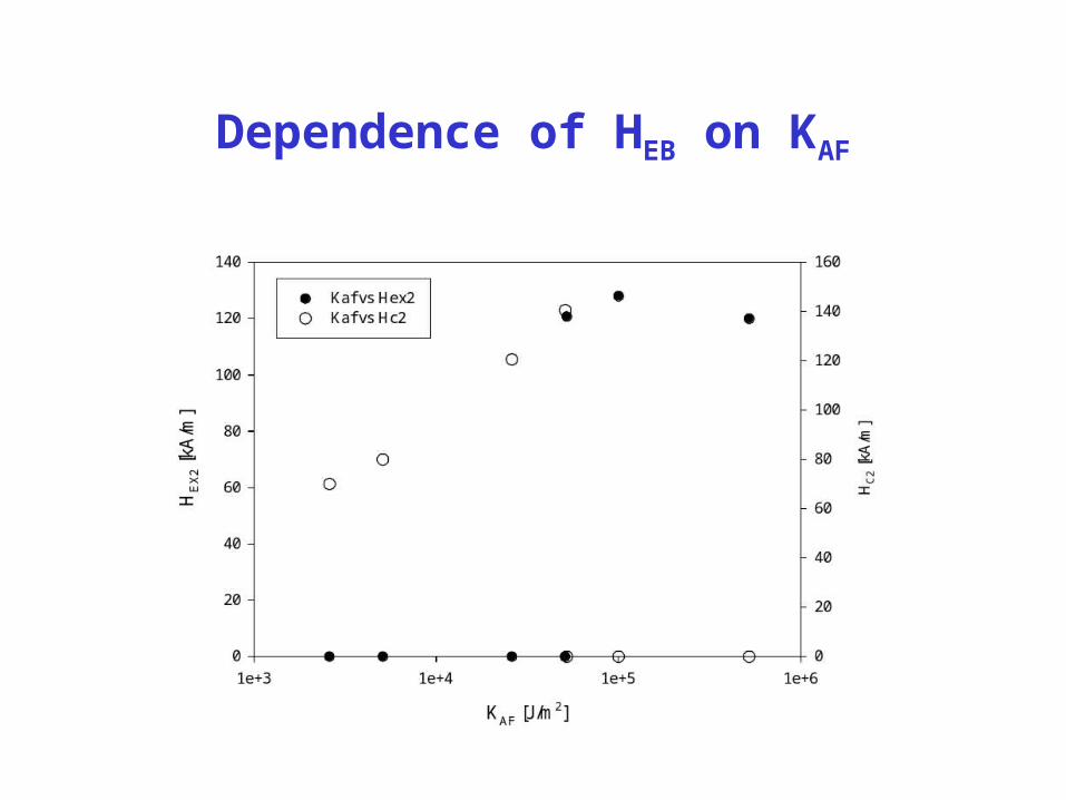
Dependence of HEB on KAF
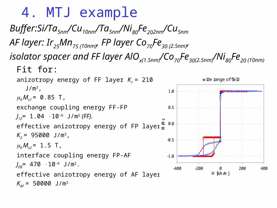
4. MTJ example
Fit for: anizotropy energy of FF layer K1 = 210 J/m3,
0 Ms1 = 0.85 T,
exchange coupling energy FF-FP
J12= 1.04 10-6 J/m2 (FF).
effective anizotropy energy of FP layer
K2 = 95000 J/m3,
0 Ms2 = 1.5 T,
interface coupling energy FP-AF
JEB= 470 10-6 J/m2.
effective anizotropy energy of AF layer
KAF = 50000 J/m3
wide range of field
H [kA/m]-400 -200 0 200 400
M/M
s-1.0
-0.5
0.0
0.5
1.0
Buffer:Si/Ta5nm/Cu10nm/Ta5nm/Ni80Fe202nm/Cu5nm
AF layer: Ir25Mn75 (10nm), FP layer Co70Fe30 (2.5nm),
isolator spacer and FF layer AlOx(1.5nm)/Co70Fe30(2.5nm)/Ni80Fe20 (10nm)
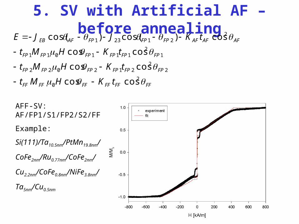
5. SV with Artificial AF – before annealing
FFFFFFFFFFFF
FPFPFPFPFPFP
FPFPFPFPFPFP
AFAFAFFPFPFPAFEB
tKHMt
tKHMt
tKHMt
tKJJE
20
22
212022
12
111011
221231
coscos
coscos
coscos
cos)cos()cos(
AFF-SV: AF/FP1/S1/FP2/S2/FF
Example:
Si(111)/Ta10.5nm/PtMn19.8nm/
CoFe2nm/Ru0.77nm/CoFe2nm/
Cu2.2nm/CoFe0.8nm/NiFe3.8nm/
Ta5nm/Cu0.5nm

• “To do” list for MAGEN2 program • bugs fixing experimental data in background more layers• 3D axis of anisotropy and field definition animation of magnetisation vector of each
ferromagnetic layer during simulation process• GMR/TMR characteristics

END
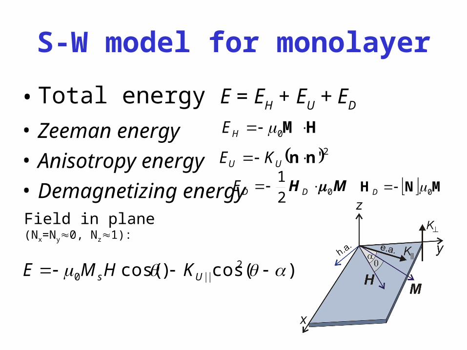
S-W model for monolayer
• Total energy E = EH + EU + ED
• Zeeman energy
• Anisotropy energy
• Demagnetizing energy
2'nn UU KE
MH 021 DDE
HM 0HE
MNH 0D
Field in plane (Nx=Ny0, Nz1):
)(cos)cos( 20 Us KHME
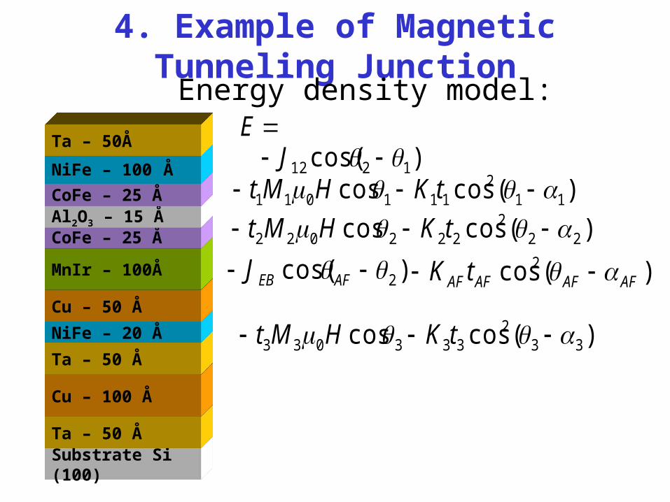
4. Example of Magnetic Tunneling Junction
Substrate Si (100)
Ta – 50 Å
Cu – 100 Å
Ta – 50 Å
NiFe – 20 Å
Cu – 50 Å
MnIr – 100Å
CoFe – 25 ÅAl2O3 – 15 ÅCoFe – 25 Å
NiFe – 100 Å
Ta – 50Å
Energy density model:
)(coscos 332
333033
tKHMt
E
)(cos2 AFAFAFAFtK )cos( 2 AFEBJ
)(coscos 222
222022 tKHMt
)(coscos 112
111011 tKHMt)cos( 1212 J