Embed Size (px)
Citation preview
1
2014
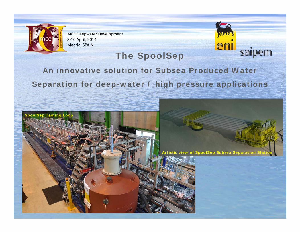
The SpoolSepAn innovative solution for Subsea Produced Water
Separation for deep-water / high pressure applications
MCE Deepwater Development8‐10 April, 2014Madrid, SPAIN
Artistic view of SpoolSep Subsea Separation Station
SpoolSep Testing Loop

2
2014
Agenda
Subsea L/L separation
SpoolSep principles and design
Qualification tests
Conclusion
3
2014
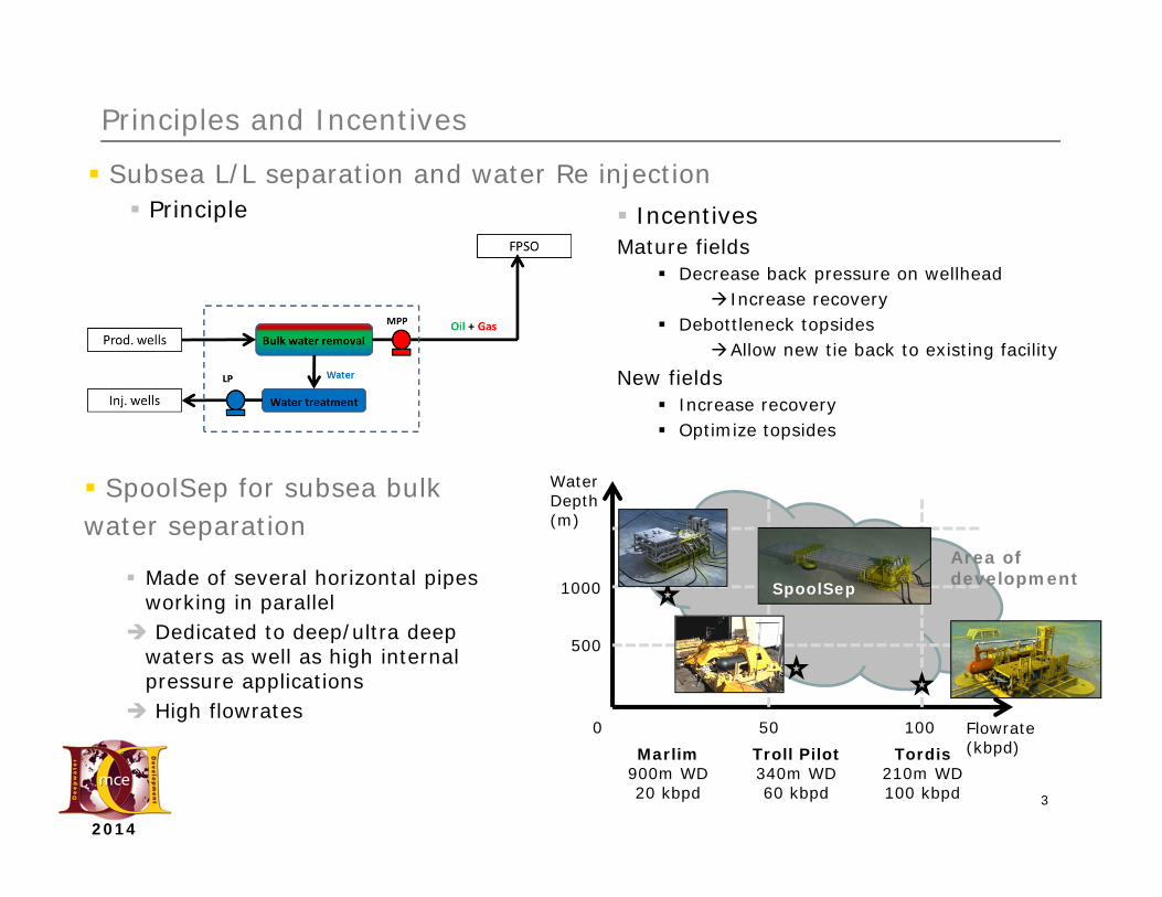
Principles and Incentives
Subsea L/L separation and water Re injection Principle
SpoolSep for subsea bulkwater separation
Made of several horizontal pipes working in parallel
Dedicated to deep/ultra deepwaters as well as high internalpressure applications
High flowrates
IncentivesMature fields
Decrease back pressure on wellhead Increase recovery
Debottleneck topsidesAllow new tie back to existing facility
New fields Increase recovery Optimize topsides
Flowrate(kbpd)
Water Depth(m)
500
1000
100500Marlim
900m WD 20 kbpd
Tordis210m WD100 kbpd
Troll Pilot340m WD60 kbpd
Area of developmentSpoolSep

4
2014
SpoolSep Liquid/Liquid Separator SpoolSep
Does not require Large Pressure Vessels Suitable for Deep and Ultra Deepwater Reliable Process Design (Gravity Separation) Good Slug Handling Capabilities Modular system : based on deepwater spools
design “Off the Shelf” Components
Subsea Station Architecture
2 foundations 1 for the station with all the process
1 smaller for pipes support
1 subsea station with main process equipment All active parts gathered on the same structure
standard integration and test principleDeoiler Module
DesanderModule
SpoolSep
PumpsModules
Splitter and collectors
5
2014
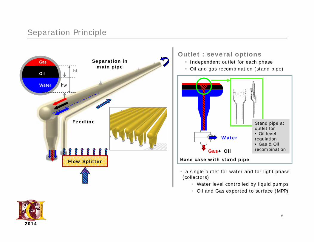
Separation Principle
Flow Splitter
Outlet : several options Independent outlet for each phase Oil and gas recombination (stand pipe)
Gas
Oil
Water hw
hL
Feedline
Separation in main pipe
Water
Base case with stand pipe
Gas+ Oil
a single outlet for water and for light phase (collectors)
• Water level controlled by liquid pumps• Oil and Gas exported to surface (MPP)
Stand pipe at outlet for • Oil level regulation• Gas & Oil recombination
6
2014
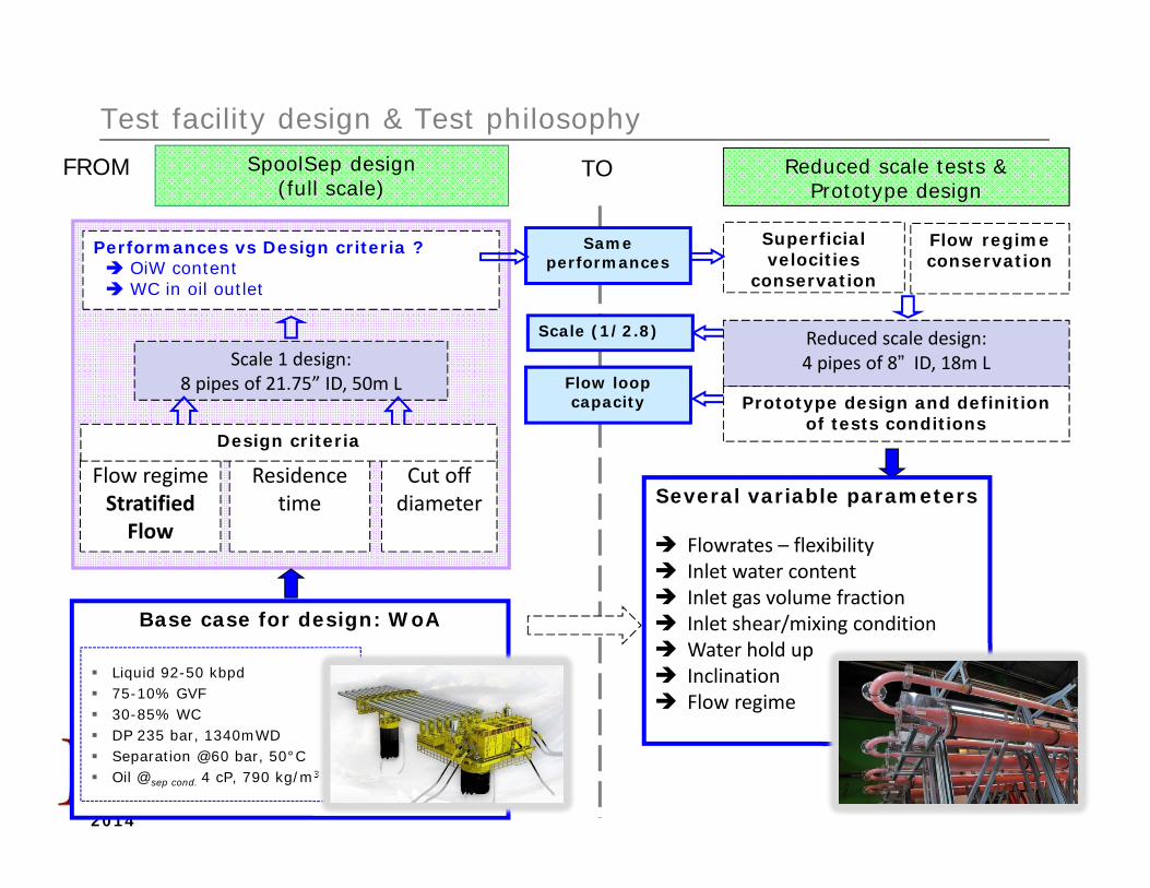
Scale 1 design:8 pipes of 21.75” ID, 50m L
Test facility design & Test philosophy
Residence time
Cut off diameter
Superficial velocities
conservation
SpoolSep design (full scale)
Reduced scale tests & Prototype design
FROM TO
Several variable parameters
Flowrates – flexibility Inlet water content Inlet gas volume fraction Inlet shear/mixing condition Water hold up Inclination Flow regime
Scale (1/2.8)
Flow loop capacity
Base case for design: WoA
Performances vs Design criteria ? OiW content WC in oil outlet
Flow regimeStratifiedFlow
Flow regimeconservation
Reduced scale design:4 pipes of 8” ID, 18m L
Same performances
Prototype design and definition of tests conditions
Liquid 92-50 kbpd 75-10% GVF 30-85% WC DP 235 bar, 1340mWD Separation @60 bar, 50°C Oil @sep cond. 4 cP, 790 kg/m3
Design criteria

7
2014
Flow Loop Principle
Test facility at Nantes
GasOil
Water
Collectors
Outlets
8
2014
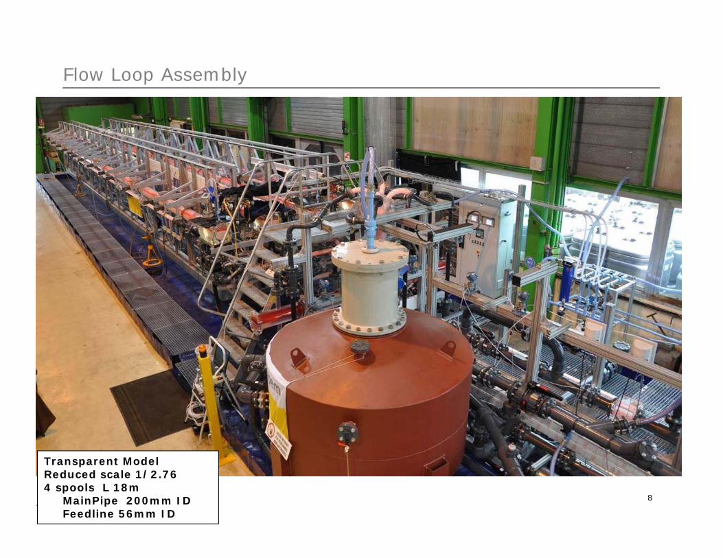
Transparent ModelReduced scale 1/2.764 spools L 18m
MainPipe 200mm IDFeedline 56mm ID
Flow Loop Assembly

9
2014
Part 1 Experimental Program: Separation performances
144 tests 4 spools working in parallel Data acquisition Photos /films Operating points Flow patterns
T6_ Ql_40m3/h_WC35%_GVF0%
Horizontal flows
10
2014
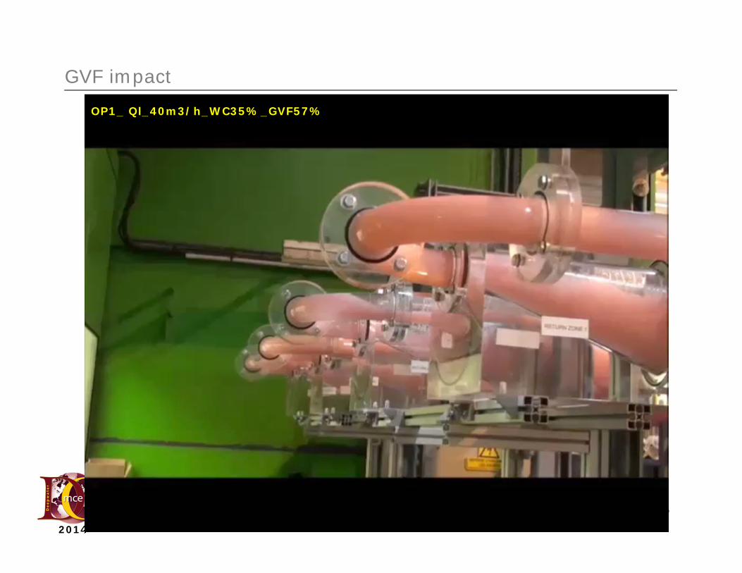
GVF impact
OP1_ Ql_40m3/h_WC35%_GVF57%
11
2014
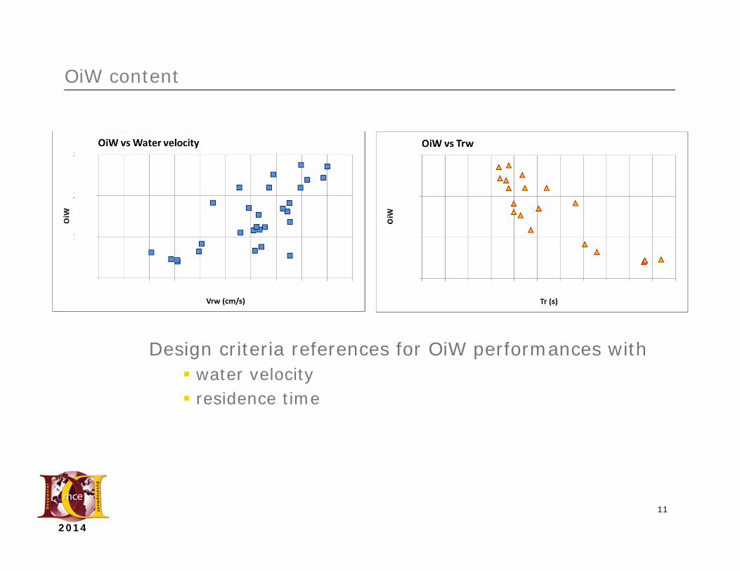
OiW content
Design criteria references for OiW performances with water velocity residence time
12
2014
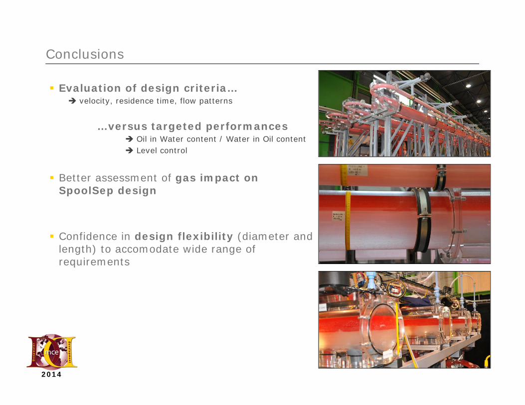
Conclusions
Evaluation of design criteria… velocity, residence time, flow patterns
…versus targeted performances Oil in Water content / Water in Oil content Level control
Better assessment of gas impact on SpoolSep design
Confidence in design flexibility (diameter and length) to accomodate wide range of requirements
13
2014
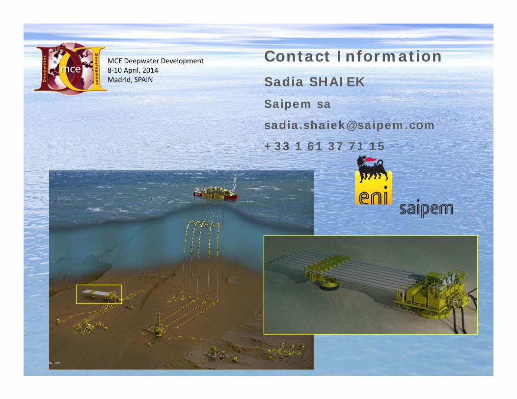
Contact InformationSadia SHAIEKSaipem sa
+33 1 61 37 71 15
MCE Deepwater Development8‐10 April, 2014Madrid, SPAIN


![TOTAL ENGINEERED SOLUTIONS - Clisby · PDF fileunit from the wellhead water pump. This fail safe operation is also used during the unit/s start-up. ... Wellhead Desander Brochure_[1][1].pdf](https://img.pdfslide.us/doc/110x75/5aaaa4f47f8b9a77188e70f8/total-engineered-solutions-clisby-from-the-wellhead-water-pump-this-fail-safe.jpg)