Embed Size (px)
Citation preview
8/10/2019 Inline Standalone Desander Manual
http://slidepdf.com/reader/full/inline-standalone-desander-manual 1/24
Inline DesanderStandalone
Issued 15 Apr 10
Maintenance & Operation Manual
Derrick Equipment Company15630 Export Plaza Drive
Houston, Texas 77032Phone: 281.590.3003
Toll Free: 1.866.DERRICKFax: 281.442.6948
www.derrickequipment.com

8/10/2019 Inline Standalone Desander Manual
http://slidepdf.com/reader/full/inline-standalone-desander-manual 2/24
8/10/2019 Inline Standalone Desander Manual
http://slidepdf.com/reader/full/inline-standalone-desander-manual 3/24
UNIT NUMBER IS KEY TO DERRICK SERVICE
All inquiries to Derrick must include the equipment unit number. Thestainless steel unit number tag attached to each piece of Derrick equipmentis your key to efficient service and support.
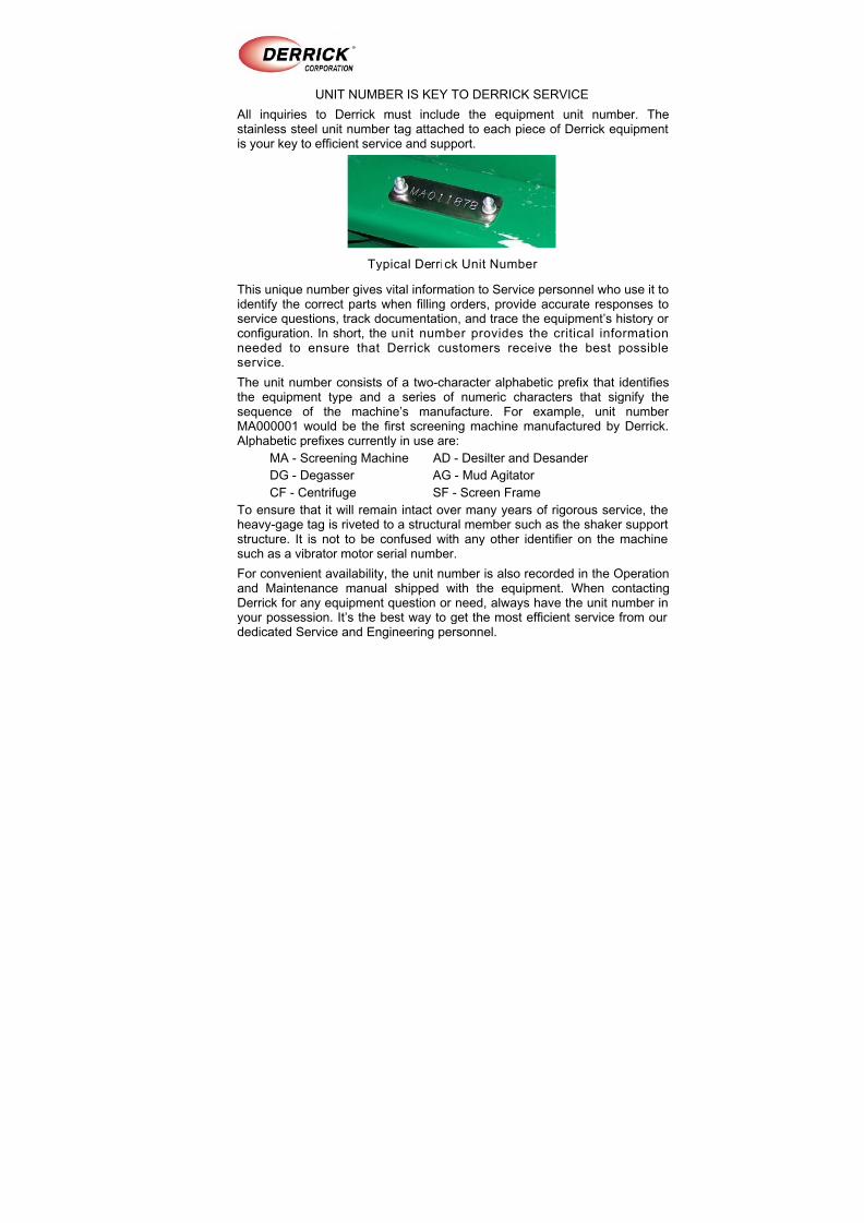
Typical Derrick Unit Number
This unique number gives vital information to Service personnel who use it toidentify the correct parts when filling orders, provide accurate responses toservice questions, track documentation, and trace the equipment’s history orconfiguration. In short, the unit number provides the critical informationneeded to ensure that Derrick customers receive the best possibleservice.
The unit number consists of a two-character alphabetic prefix that identifiesthe equipment type and a series of numeric characters that signify the
sequence of the machine’s manufacture. For example, unit numberMA000001 would be the first screening machine manufactured by Derrick.
Alphabetic prefixes currently in use are:
MA - Screening Machine AD - Desilter and Desander
DG - Degasser AG - Mud Agitator
CF - Centrifuge SF - Screen Frame
To ensure that it will remain intact over many years of rigorous service, theheavy-gage tag is riveted to a structural member such as the shaker supportstructure. It is not to be confused with any other identifier on the machine
such as a vibrator motor serial number.
For convenient availability, the unit number is also recorded in the Operationand Maintenance manual shipped with the equipment. When contactingDerrick for any equipment question or need, always have the unit number inyour possession. It’s the best way to get the most efficient service from ourdedicated Service and Engineering personnel.
8/10/2019 Inline Standalone Desander Manual
http://slidepdf.com/reader/full/inline-standalone-desander-manual 4/24
ABOUT THIS MANUAL
In this electronic manual, all sections and paragraphs listed in the CONTENTSare linked to the corresponding text.
Navigate the electronic manual as follows:
1. To view any desired information, display the CONTENTS page and move thecursor to the desired paragraph or section title.
2. To display the desired information, click on the listing when the point ingfinger appears over the text.
3. When finished viewing the text, press Alt + left arrow key to return to theCONTENTS page.
4. If desired to return to the same information, press Alt + right arrow. To locatea different item, repeat steps 1 and 2.
5. Blank pages are included to facili tate accurate two-sided printing on astandard copier. To print any individual section, simply enter the PDF pagenumber range at the top of the screen (not the page number at the bottom ofeach page).
This document contains proprietary information of Derrick Corporation. It is intended solely for the information and use of partiesoperating and maintaining the equipment described herein. Such proprietary information may not be used, reproduced, or disclosedto any other parties for any other purpose without the expressed written permission of Derrick Corporation.
Continuous improvement is a policy of Derrick Corporation. All instructions and procedures are subject to change without notice.
8/10/2019 Inline Standalone Desander Manual
http://slidepdf.com/reader/full/inline-standalone-desander-manual 5/24
CONTENTSINLINE DESANDER - STANDALONE
15 Apr 10 TOC
Page
Description ................................................................................................................ 1
Theory of Operation .................................................................................................. 3
Hydrocyclone Removal and Installation .................................................................... 5
Hydrocyclone Adjustment.......................................................................................... 7
Recommended Operating Pressures ........................................................................ 8
Nominal Flow Rates .................................................................................................. 9
Replacement Parts.................................................................................................... 9

8/10/2019 Inline Standalone Desander Manual
http://slidepdf.com/reader/full/inline-standalone-desander-manual 6/24
8/10/2019 Inline Standalone Desander Manual
http://slidepdf.com/reader/full/inline-standalone-desander-manual 7/24
10” DESANDER - STANDALONE
DESCRIPTION
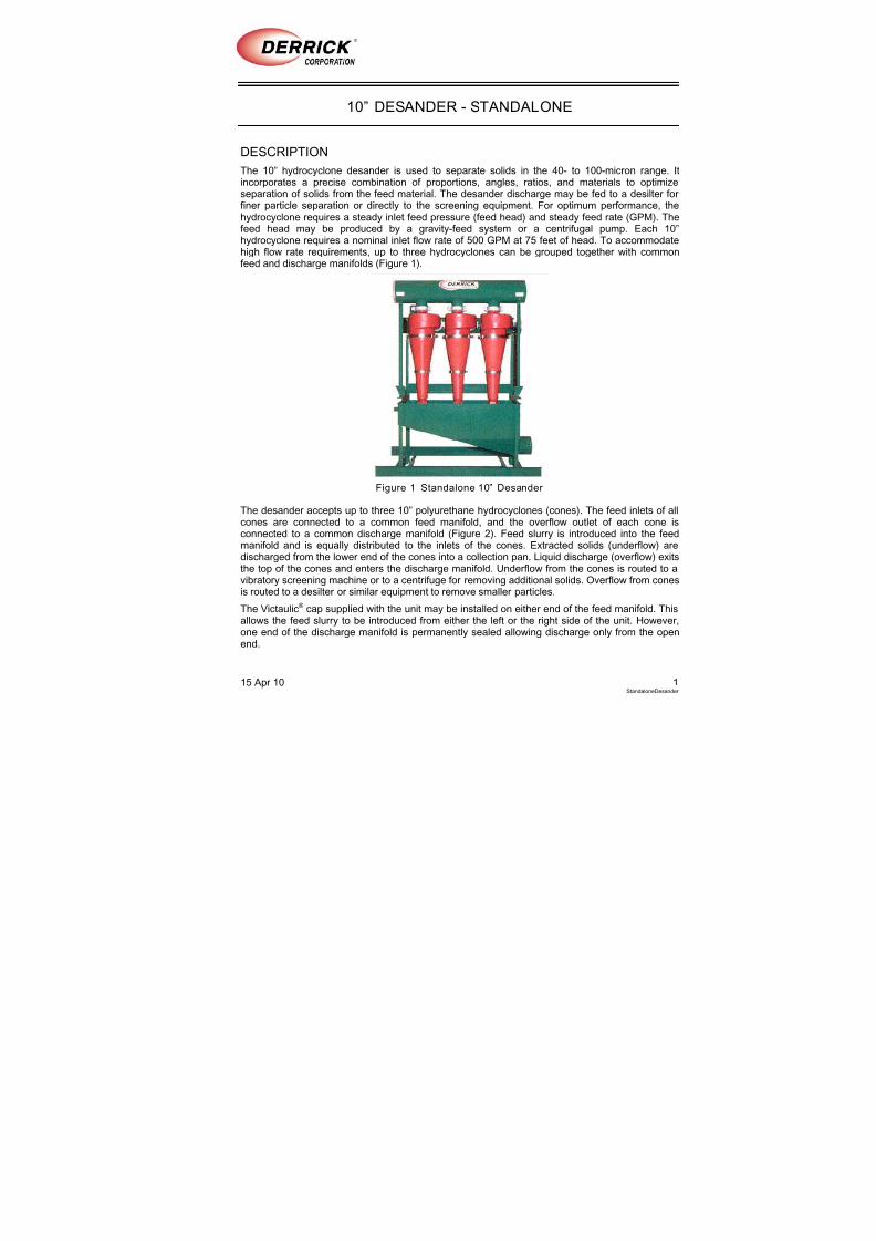
The 10” hydrocyclone desander is used to separate solids in the 40- to 100-micron range. Itincorporates a precise combination of proportions, angles, ratios, and materials to optimizeseparation of solids from the feed material. The desander discharge may be fed to a desilter forfiner particle separation or directly to the screening equipment. For optimum performance, thehydrocyclone requires a steady inlet feed pressure (feed head) and steady feed rate (GPM). Thefeed head may be produced by a gravity-feed system or a centrifugal pump. Each 10”hydrocyclone requires a nominal inlet flow rate of 500 GPM at 75 feet of head. To accommodatehigh flow rate requirements, up to three hydrocyclones can be grouped together with commonfeed and discharge manifolds (Figure 1).
Figure 1 Standalone 10” Desander
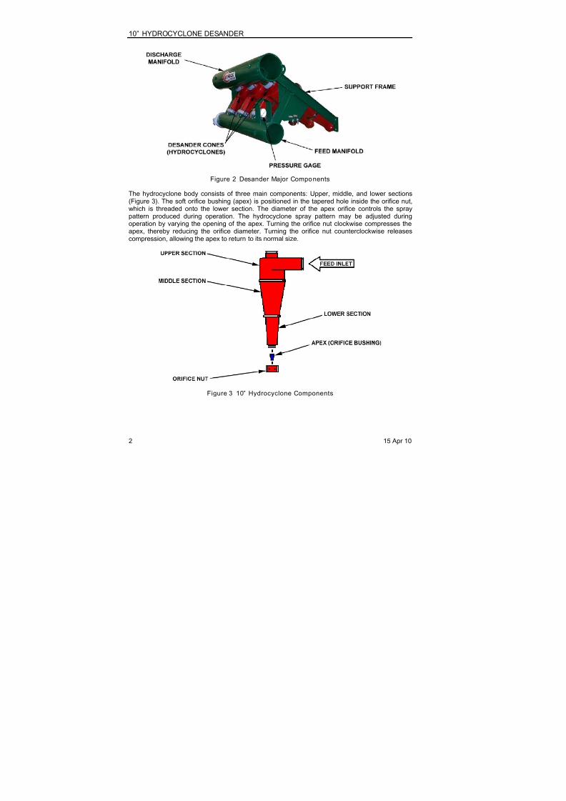
The desander accepts up to three 10” polyurethane hydrocyclones (cones). The feed inlets of allcones are connected to a common feed manifold, and the overflow outlet of each cone isconnected to a common discharge manifold (Figure 2). Feed slurry is introduced into the feedmanifold and is equally distributed to the inlets of the cones. Extracted solids (underflow) are
discharged from the lower end of the cones into a collection pan. Liquid discharge (overflow) exitsthe top of the cones and enters the discharge manifold. Underflow from the cones is routed to avibratory screening machine or to a centrifuge for removing additional solids. Overflow from conesis routed to a desilter or similar equipment to remove smaller particles.
The Victaulic® cap supplied with the unit may be installed on either end of the feed manifold. Thisallows the feed slurry to be introduced from either the left or the right side of the unit. However,one end of the discharge manifold is permanently sealed allowing discharge only from the openend.
15 Apr 10 1StandaloneDesander
8/10/2019 Inline Standalone Desander Manual
http://slidepdf.com/reader/full/inline-standalone-desander-manual 8/24
10” HYDROCYCLONE DESANDER
Figure 2 Desander Major Components
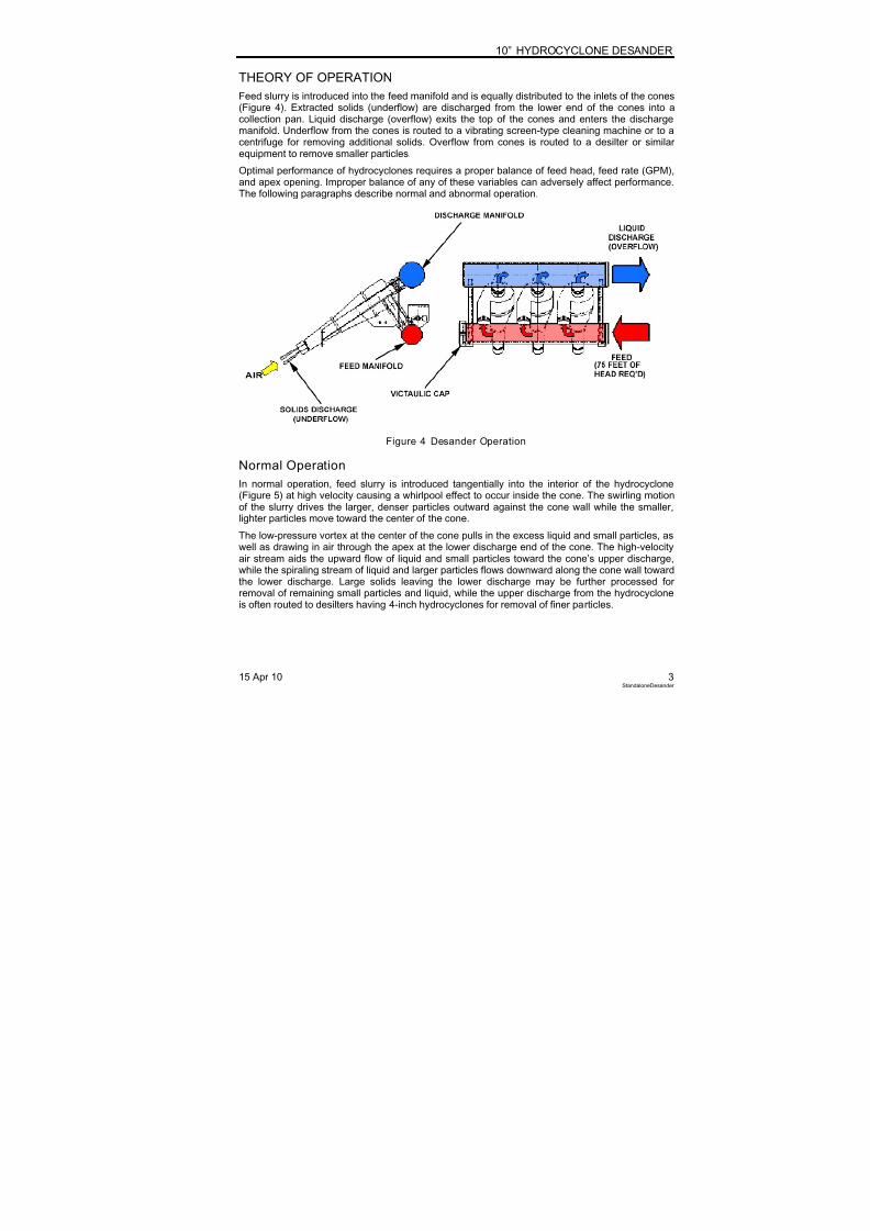
The hydrocyclone body consists of three main components: Upper, middle, and lower sections(Figure 3). The soft orifice bushing (apex) is positioned in the tapered hole inside the orifice nut,which is threaded onto the lower section. The diameter of the apex orifice controls the spraypattern produced during operation. The hydrocyclone spray pattern may be adjusted duringoperation by varying the opening of the apex. Turning the orifice nut clockwise compresses theapex, thereby reducing the orifice diameter. Turning the orifice nut counterclockwise releasescompression, allowing the apex to return to its normal size.
Figure 3 10” Hydrocyclone Components
2 15 Apr 10
8/10/2019 Inline Standalone Desander Manual
http://slidepdf.com/reader/full/inline-standalone-desander-manual 9/24
10” HYDROCYCLONE DESANDER
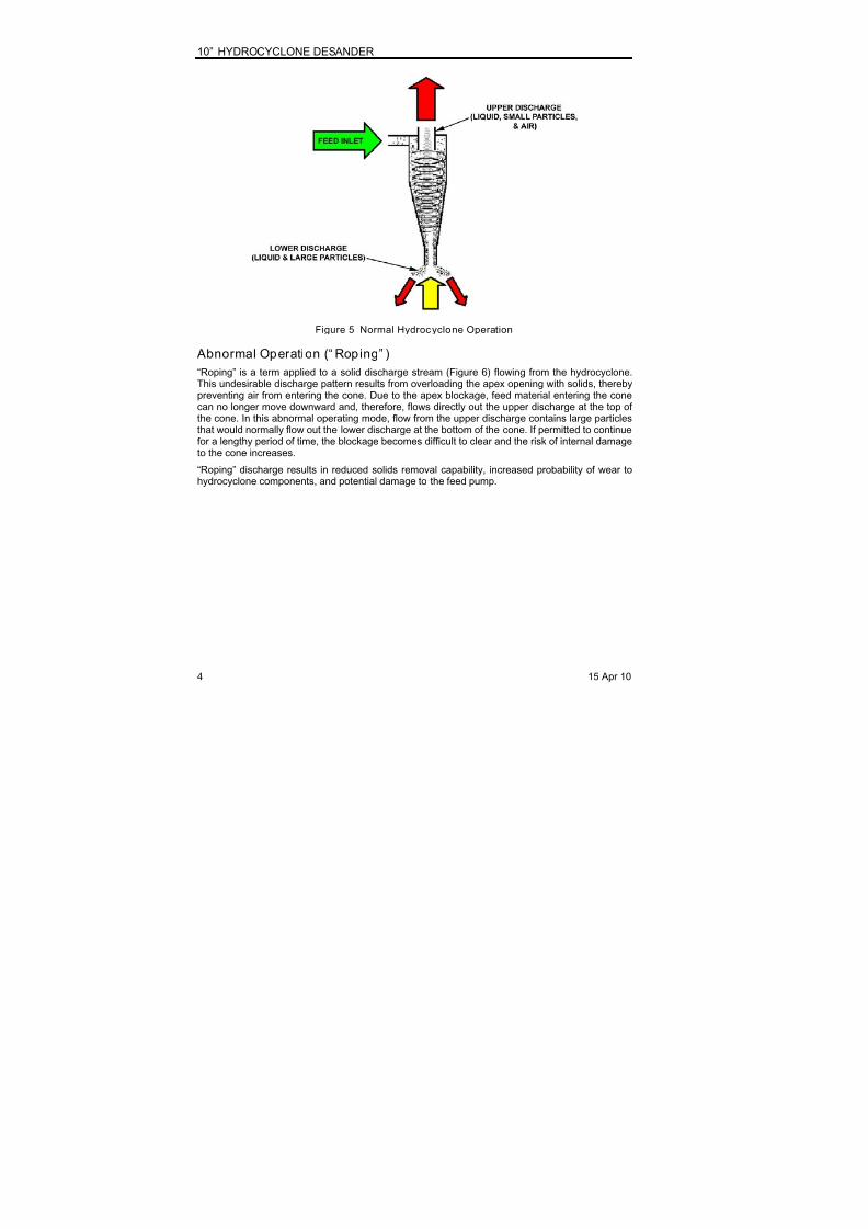
THEORY OF OPERATION
Feed slurry is introduced into the feed manifold and is equally distributed to the inlets of the cones(Figure 4). Extracted solids (underflow) are discharged from the lower end of the cones into acollection pan. Liquid discharge (overflow) exits the top of the cones and enters the dischargemanifold. Underflow from the cones is routed to a vibrating screen-type cleaning machine or to a
centrifuge for removing additional solids. Overflow from cones is routed to a desilter or similarequipment to remove smaller particles.
Optimal performance of hydrocyclones requires a proper balance of feed head, feed rate (GPM),and apex opening. Improper balance of any of these variables can adversely affect performance.The following paragraphs describe normal and abnormal operation.
Figure 4 Desander Operation
Normal Operation
In normal operation, feed slurry is introduced tangentially into the interior of the hydrocyclone(Figure 5) at high velocity causing a whirlpool effect to occur inside the cone. The swirling motionof the slurry drives the larger, denser particles outward against the cone wall while the smaller,lighter particles move toward the center of the cone.
The low-pressure vortex at the center of the cone pulls in the excess liquid and small particles, aswell as drawing in air through the apex at the lower discharge end of the cone. The high-velocity
air stream aids the upward flow of liquid and small particles toward the cone’s upper discharge,while the spiraling stream of liquid and larger particles flows downward along the cone wall towardthe lower discharge. Large solids leaving the lower discharge may be further processed forremoval of remaining small particles and liquid, while the upper discharge from the hydrocycloneis often routed to desilters having 4-inch hydrocyclones for removal of finer particles.
15 Apr 10 3StandaloneDesander
8/10/2019 Inline Standalone Desander Manual
http://slidepdf.com/reader/full/inline-standalone-desander-manual 10/24
10” HYDROCYCLONE DESANDER
Figure 5 Normal Hydrocyclone Operation
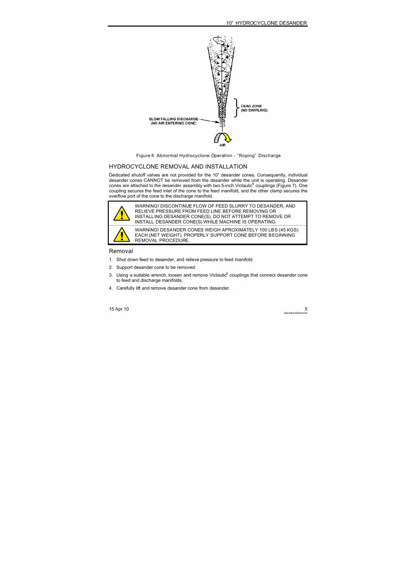
Abnormal Operation (“ Roping” )
“Roping” is a term applied to a solid discharge stream (Figure 6) flowing from the hydrocyclone.This undesirable discharge pattern results from overloading the apex opening with solids, therebypreventing air from entering the cone. Due to the apex blockage, feed material entering the conecan no longer move downward and, therefore, flows directly out the upper discharge at the top of
the cone. In this abnormal operating mode, flow from the upper discharge contains large particlesthat would normally flow out the lower discharge at the bottom of the cone. If permitted to continuefor a lengthy period of time, the blockage becomes difficult to clear and the risk of internal damageto the cone increases.
“Roping” discharge results in reduced solids removal capability, increased probability of wear tohydrocyclone components, and potential damage to the feed pump.
4 15 Apr 10
8/10/2019 Inline Standalone Desander Manual
http://slidepdf.com/reader/full/inline-standalone-desander-manual 11/24
10” HYDROCYCLONE DESANDER
Figure 6 Abnormal Hydrocyclone Operation - “Roping” Discharge
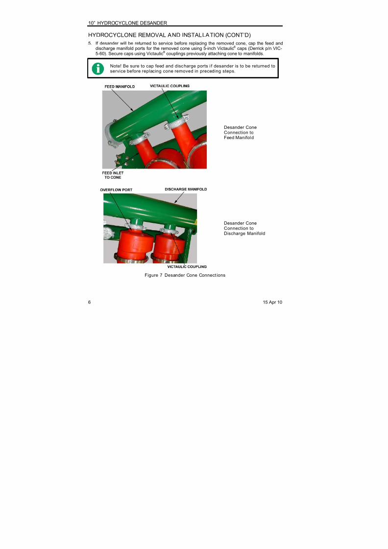
HYDROCYCLONE REMOVAL AND INSTALLATION
Dedicated shutoff valves are not provided for the 10” desander cones. Consequently, individualdesander cones CANNOT be removed from the desander while the unit is operating. Desandercones are attached to the desander assembly with two 5-inch Victaulic® couplings (Figure 7). One
coupling secures the feed inlet of the cone to the feed manifold, and the other clamp secures theoverflow port of the cone to the discharge manifold.
WARNING! DISCONTINUE FLOW OF FEED SLURRY TO DESANDER, ANDRELIEVE PRESSURE FROM FEED LINE BEFORE REMOVING ORINSTALLING DESANDER CONE(S). DO NOT ATTEMPT TO REMOVE ORINSTALL DESANDER CONE(S) WHILE MACHINE IS OPERATING.
WARNING! DESANDER CONES WEIGH APROXIMATELY 100 LBS (45 KGS)EACH (NET WEIGHT). PROPERLY SUPPORT CONE BEFORE BEGINNINGREMOVAL PROCEDURE.
Removal1. Shut down feed to desander, and relieve pressure to feed manifold.
2. Support desander cone to be removed.
3. Using a suitable wrench, loosen and remove Victaulic® couplings that connect desander coneto feed and discharge manifolds.
4. Carefully lift and remove desander cone from desander.
15 Apr 10 5StandaloneDesander
8/10/2019 Inline Standalone Desander Manual
http://slidepdf.com/reader/full/inline-standalone-desander-manual 12/24
10” HYDROCYCLONE DESANDER
HYDROCYCLONE REMOVAL AND INSTALLATION (CONT’D)
5. If desander will be returned to service before replacing the removed cone, cap the feed anddischarge manifold ports for the removed cone using 5-inch Victaulic® caps (Derrick p/n VIC-5-60). Secure caps using Victaulic® couplings previously attaching cone to manifolds.
Note! Be sure to cap feed and discharge ports i f desander is to be returned toservice before replacing cone removed in preceding steps.
Desander ConeConnection toFeed Manifold
Desander ConeConnection toDischarge Manifold
Figure 7 Desander Cone Connect ions
6 15 Apr 10

8/10/2019 Inline Standalone Desander Manual
http://slidepdf.com/reader/full/inline-standalone-desander-manual 13/24
10” HYDROCYCLONE DESANDER
Installation
1. Shut down feed to desander, and relieve pressure to feed manifold.
2. If Victaulic® caps were installed, remove caps from ports on feed and discharge manifolds.
3. Install coupling gaskets on feed and discharge manifold ports.
4. Support desander cone, and align inlet and outlet ports of cone with corresponding ports onthe feed and discharge manifolds.
5. Center coupling gasket between the coupling grooves in both the cone and manifold pipe.Place Victaulic® coupling halves on joint being sure that gasket remains centered on cone andmanifold pipe grooves.
HYDROCYCLONE ADJUSTMENT
Hydrocyclones must be properly adjusted to operate efficiently. Tightening the orifice nut (turningclockwise) compresses the apex and thereby reduces its orifice diameter. Loosening the orificenut (turning counterclockwise) releases the compression, allowing the apex to return to its normal
size. The following paragraphs describe the spray pattern adjustments to achieve optimalperformance.
Spray Patterns
The spray pattern varies in response to the feed head (inlet pressure), feed rate, andhydrocyclone apex opening. To maximize overall desander efficiency, the spray pattern of eachcone must be balanced for optimal performance. This is done by observing the lower dischargepattern and then adjusting the apex opening to achieve the correct discharge angle (Figure 8) forthe prevailing feed rate and inlet pressure.
Figure 8 Spray Patterns - 10” Hydrocyclones
15 Apr 10 7StandaloneDesander
8/10/2019 Inline Standalone Desander Manual
http://slidepdf.com/reader/full/inline-standalone-desander-manual 14/24
10” HYDROCYCLONE DESANDER
Spray Pattern Versus PerformanceThe three spray patterns shown in Figure 8 are interpreted as follows:
TOO WIDE - Spray angle greater than 30° with a hollow center. In normal operation, thispattern is undesirable. This spray pattern indicates that the exit diameter of
the apex is too large, and an excessive amount of liquid discharges along withthe solids flowing from the bottom of the cone.
Correct this cond ition by tightening orifice nut (turning clockwise) untildesired spray profil e is achieved.
CORRECT - Spray angle in the range of 20° to 30° with a hollow center. In normaloperation, this pattern is desirable.
No adjustment required.
TOO NARROW - Spray angle less than 20° with a hollow center. In normal operation, thispattern is undesirable. This spray pattern indicates exit diameter of the apex istoo small, the solids discharge is too dry, and excessive solids are beingdischarged with the liquid from the upper discharge.
Correct this cond ition by loosening orifice nut (turningcounterclockwise) until desired spray profile is achieved.
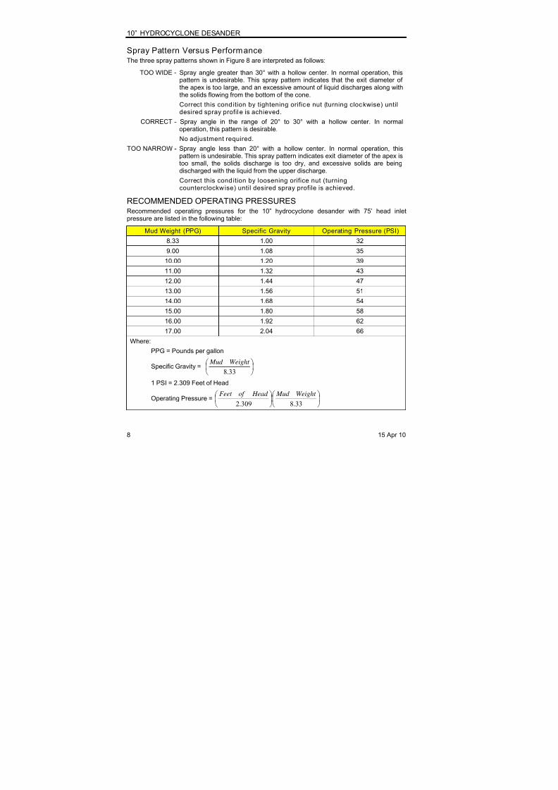
RECOMMENDED OPERATING PRESSURESRecommended operating pressures for the 10” hydrocyclone desander with 75’ head inletpressure are listed in the following table:
Mud Weight (PPG) Specific Gravity Operating Pressure (PSI)
8.33 1.00 32
9.00 1.08 35
10.00 1.20 39
11.00 1.32 43
12.00 1.44 47
13.00 1.56 51
14.00 1.68 54
15.00 1.80 58
16.00 1.92 62
17.00 2.04 66
Where:
PPG = Pounds per gallon
Specific Gravity =
33.8
Weight Mud
1 PSI = 2.309 Feet of Head
Operating Pressure =
33.8309.2
Weight Mud Head of Feet
8 15 Apr 10
8/10/2019 Inline Standalone Desander Manual
http://slidepdf.com/reader/full/inline-standalone-desander-manual 15/24
10” HYDROCYCLONE DESANDER
15 Apr 10 9StandaloneDesander
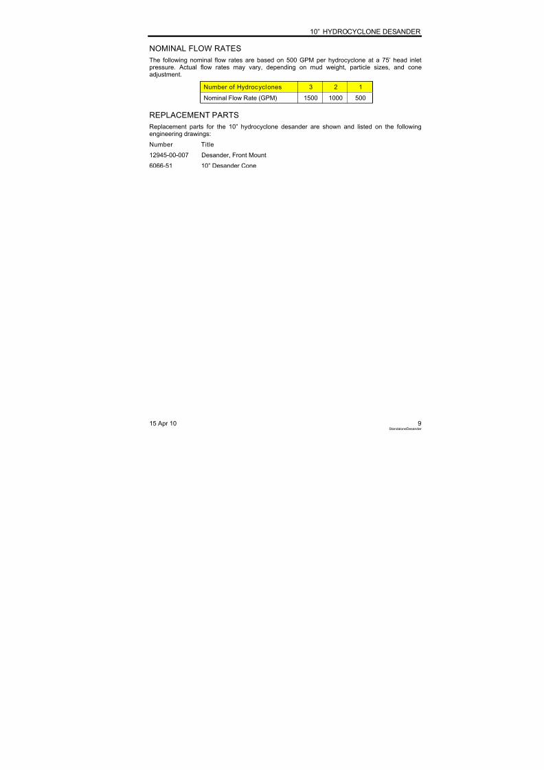
NOMINAL FLOW RATES
The following nominal flow rates are based on 500 GPM per hydrocyclone at a 75’ head inletpressure. Actual flow rates may vary, depending on mud weight, particle sizes, and coneadjustment.
Number of Hydrocyclones 3 2 1
Nominal Flow Rate (GPM) 1500 1000 500
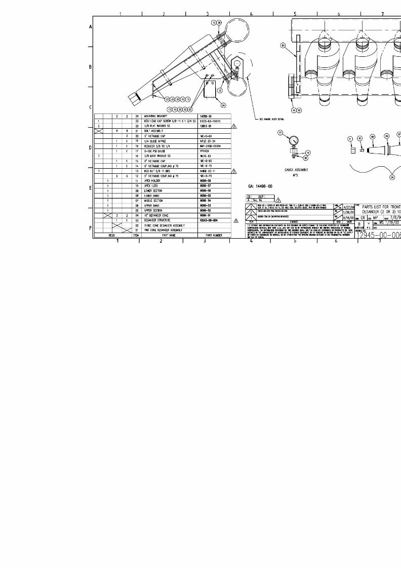
REPLACEMENT PARTS
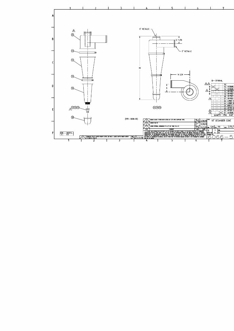
Replacement parts for the 10” hydrocyclone desander are shown and listed on the followingengineering drawings:
Number Title
12945-00-007 Desander, Front Mount
6066-51 10” Desander Cone

8/10/2019 Inline Standalone Desander Manual
http://slidepdf.com/reader/full/inline-standalone-desander-manual 16/24
8/10/2019 Inline Standalone Desander Manual
http://slidepdf.com/reader/full/inline-standalone-desander-manual 17/24

8/10/2019 Inline Standalone Desander Manual
http://slidepdf.com/reader/full/inline-standalone-desander-manual 18/24
8/10/2019 Inline Standalone Desander Manual
http://slidepdf.com/reader/full/inline-standalone-desander-manual 19/24

8/10/2019 Inline Standalone Desander Manual
http://slidepdf.com/reader/full/inline-standalone-desander-manual 20/24
8/10/2019 Inline Standalone Desander Manual
http://slidepdf.com/reader/full/inline-standalone-desander-manual 21/24
®
Document No.: PE-S-299-03-03
http://dmc-sps/qc/Certificates/Origin Standard/PE-S-299-03-03.docRevison Number 2Revision Date: 28-December-2011
CERTIFICATE OF ORIGIN
Equipment: Desilters and/or Desanders
Model: Round Desilter, Inline Stand-Alone Desilter, InlineStand-Alone Desander
Characteristics: N/A
Derrick Corporation acknowledges that the above set-forth product is manufactured in the United States of America as of the date of this certificate. This certificate is governed by the applicable purchase order termsin effect at the time of Derrick Corporation’s original shipment of the referenced product.
Date: 28-December-2011 Signature: Jennifer J. PolanowskiDerrick Corporation
8/10/2019 Inline Standalone Desander Manual
http://slidepdf.com/reader/full/inline-standalone-desander-manual 22/24
®
Document No.: PE-S-075-08-00
http://dmc-sps/qc/Certificates/Quality/PE-S-075-08-00.docRevison Number 2Revision Date: 29-December-2011
CERTIFICATE OF QUALITY
Equipment: Desilters and/or Desanders
Model: Round Desilter, Inline Stand-Alone Desilter, InlineStand Alone Desander
Characteristics: N/A
Derrick Corporation acknowledges that the above set-forth product conformed to the requirements for theapplicable purchase order at the time of its original shipment by Derrick Corporation in that all constructionmaterials and components were new and unused, were manufactured for this product, and that it was free ofany known defects as to their design, material and workmanship. This certificate is governed by theapplicable purchase order terms in effect at the time of Derrick Corporation’s original shipment of thereferenced product.
Date: 29-December-2011 Signature: Jennifer J. PolanowskiDerrick Corporation

8/10/2019 Inline Standalone Desander Manual
http://slidepdf.com/reader/full/inline-standalone-desander-manual 23/24
®
Document No.: PE-S-543-04-00
http://dmc-sps/qc/Certificates/Shipping Final Inspection and Run Test/PE-S-543-04-00.docRevison Number 2Revision Date: 29-December-2011
SHIPPING FINAL INSPECTION
AND RUN TEST CERTIFICATE
Equipment: Desilters and/or Desanders
Model: Round Desilter, Inline Stand-Alone Desilter, InlineStand-Alone Desander
Characteristics: N/A
The product listed above was inspected and found to be in conformance with Derrick Corporation’s internalcoating, run test, and assembly inspection documents that were required for the type of equipmentmanufactured in accordance with the Derrick quality system. This certificate is governed by the applicablepurchase order terms in effect at the time of Derrick Corporation’s original shipment of the referencedproduct.
Date: 29-December-2011 Signature: Jennifer J. PolanowskiDerrick Corporation
8/10/2019 Inline Standalone Desander Manual
http://slidepdf.com/reader/full/inline-standalone-desander-manual 24/24