Embed Size (px)
Citation preview
1
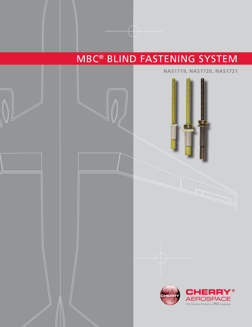
MBC® BLIND FASTENING SYSTEM
SPS Fastener Division, a PCC Company
NAS1719, NAS1720, NAS1721

MBC® Features & Benefits ........................................................................................1–2
MBC® Rivet SelectionProduct Numbering & NAS Conversion ............................................................................3Installed Weight, Grip Advantages & Part Conversion ..................................................4–5
MBC® Rivet Standards PagesMBC® Locked Stem Rivet NAS1719: 100° Reduced Flush Head Nominal Diameter ..........6MBC® Locked Stem Rivet NAS1720: Nominal Diameter Protruding Head .........................7MBC® Locked Stem Rivet NAS1721: Nominal Diameter 100° Flush Head .........................8
MBC® Installation Tooling ......................................................................................9–11
LIMITED WARRANTY
Seller warrants the goods conform to applicable specifications and drawings and will be manufactured and inspected according to generally accepted practices of companies manufacturing industrial or aerospace fasteners. In the event of any breach of the foregoing warranty, Buyer’s sole remedy shall be to return defective goods (after receiving authorization from Seller) for replacement or refund of the purchase price, at the Seller’s option. Seller agrees to any freight costs in connection with the return of any defective goods, but any costs relating to removal of the defective or nonconforming goods or installation of replacement goods shall be Buyer’s responsibility. SELLER’S WARRANTY DOES NOT APPLY WHEN ANY PHYSICAL OR CHEMICAL CHANGE IN THE FORM OF THE PRODUCT IS MADE BY BUYER. THE FOREGOING EXPRESS WARRANTY AND REMEDY ARE EXCLUSIVE AND ARE IN LIEU OF ALL OTHER WARRANTIES AND REMEDIES; ANY IMPLIED WARRANTY AS TO QUALITY, FITNESS FOR PURPOSE, OR MERCHANTABILITY IS HEREBY SPECIFICALLY DISCLAIMED AND EXCLUDED BY SELLER. This warranty is void if seller is not notified in writing of any rejection of the goods within one (1) Year after initial use by buyer of any power Riveter or ninety (90) days after initial use of any other product. Seller shall not be liable under any circumstances for incidental, special or consequential damages arising in whole or in part from any breach by Seller, AND SUCH INCIDENTAL, SPECIAL, OR CONSEQUENTIAL DAMAGES ARE HEREBY EXPRESSLY EXCLUDED.
Our policy is one of continuous development. Specifications shown in this document may be subject to changes introduced after publication.
CHERRY® and MBC® are trademarks of Cherry Aerospace.
NOTE: The properties, strengths, dimensions, installed characteristics and all other information in this catalog is for guidance only to aid in the correct selection of the products described herein and is not intended or implied as part of the warranty. All applications should be evaluated for functional suitability and available samples of the described parts can be requested for installed tests, suitability and evaluations.
ATTENTION: Blind rivets are not always a suitable substitute for solid rivets. Maintenance personnel are reminded that AC 43.13-1A chapter 2, section 3, stipulates: “Do not substitute hollow rivets for solid rivets in load carrying members without specific approval of the application by a representative of the Federal Aviation Administration. Blind rivets may be used in blind locations in accordance with the conditions listed in Chapter 5, provided the edge distances and spacings are not less that the minimum listed in paragraph 99d.”
INDEX
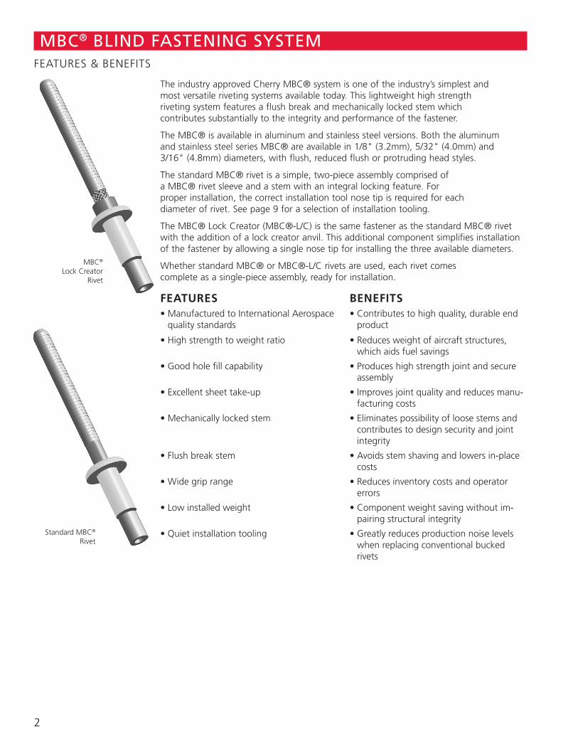
Standard MBC® Rivet
The industry approved Cherry MBC® system is one of the industry’s simplest and most versatile riveting systems available today. This lightweight high strength riveting system features a flush break and mechanically locked stem which contributes substantially to the integrity and performance of the fastener.
The MBC® is available in aluminum and stainless steel versions. Both the aluminum and stainless steel series MBC® are available in 1/8" (3.2mm), 5/32" (4.0mm) and 3/16" (4.8mm) diameters, with flush, reduced flush or protruding head styles.
The standard MBC® rivet is a simple, two-piece assembly comprised of a MBC® rivet sleeve and a stem with an integral locking feature. For proper installation, the correct installation tool nose tip is required for each diameter of rivet. See page 9 for a selection of installation tooling.
The MBC® Lock Creator (MBC®-L/C) is the same fastener as the standard MBC® rivet with the addition of a lock creator anvil. This additional component simplifies installation of the fastener by allowing a single nose tip for installing the three available diameters.
Whether standard MBC® or MBC®-L/C rivets are used, each rivet comes complete as a single-piece assembly, ready for installation.
FEATURES BENEFITS• Manufactured to International Aerospace
quality standards• Contributes to high quality, durable end
product
• High strength to weight ratio • Reduces weight of aircraft structures, which aids fuel savings
• Good hole fill capability • Produces high strength joint and secure assembly
• Excellent sheet take-up • Improves joint quality and reduces manu-facturing costs
• Mechanically locked stem • Eliminates possibility of loose stems and contributes to design security and joint integrity
• Flush break stem • Avoids stem shaving and lowers in-place costs
• Wide grip range • Reduces inventory costs and operator errors
• Low installed weight • Component weight saving without im-pairing structural integrity
• Quiet installation tooling • Greatly reduces production noise levels when replacing conventional bucked rivets
MBC®
Lock CreatorRivet
MBC® BLIND FASTENING SYSTEMFEATURES & BENEFITS
2
MBC® BLIND FASTENING SYSTEMINSTALLATION SEQUENCE & PERFORMANCE DATA
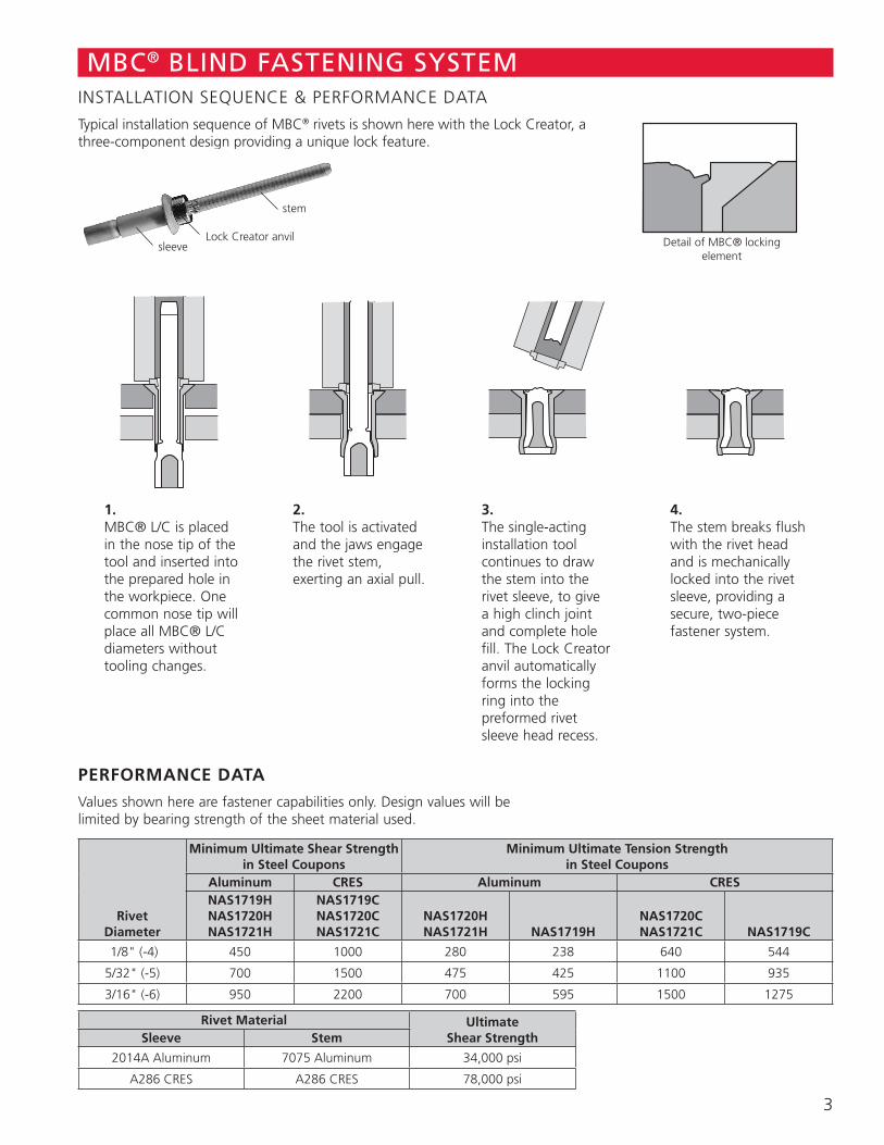
Typical installation sequence of MBC® rivets is shown here with the Lock Creator, a three-component design providing a unique lock feature.
sleeveLock Creator anvil
stem
1. MBC® L/C is placed in the nose tip of the tool and inserted into the prepared hole in the workpiece. One common nose tip will place all MBC® L/C diameters without tooling changes.
2. The tool is activated and the jaws engage the rivet stem, exerting an axial pull.
3. The single-acting installation tool continues to draw the stem into the rivet sleeve, to give a high clinch joint and complete hole fill. The Lock Creator anvil automatically forms the locking ring into the preformed rivet sleeve head recess.
4. The stem breaks flush with the rivet head and is mechanically locked into the rivet sleeve, providing a secure, two-piece fastener system.
PERFORMANCE DATA
Values shown here are fastener capabilities only. Design values will be limited by bearing strength of the sheet material used.
RivetDiameter
Minimum Ultimate Shear Strength in Steel Coupons
Minimum Ultimate Tension Strength in Steel Coupons
Aluminum CRES Aluminum CRESNAS1719H NAS1720HNAS1721H
NAS1719CNAS1720CNAS1721C
NAS1720HNAS1721H NAS1719H
NAS1720CNAS1721C NAS1719C
1/8" (-4) 450 1000 280 238 640 544
5/32" (-5) 700 1500 475 425 1100 935
3/16" (-6) 950 2200 700 595 1500 1275
Rivet Material Ultimate Shear StrengthSleeve Stem
2014A Aluminum 7075 Aluminum 34,000 psi
A286 CRES A286 CRES 78,000 psi
Detail of MBC® locking element
3
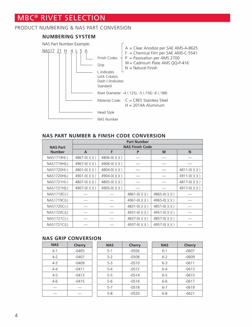
NAS PART NUMBER & FINISH CODE CONVERSION
NAS Part Number
Part NumberNAS Finish Code
A F P W N
NAS1719H(-) 4867-0( )( )( ) 4806-0( )( )( ) — — —
NAS1719H(L) 4967-0( )( )( ) 4906-0( )( )( ) — — —
NAS1720H(-) 4801-0( )( )( ) 4804-0( )( )( ) — — 4811-0( )( )( )
NAS1720H(L) 4901-0( )( )( ) 4904-0( )( )( ) — — 4911-0( )( )( )
NAS1721H(-) 4807-0( )( )( ) 4805-0( )( )( ) — — 4817-0( )( )( )
NAS1721H(L) 4907-0( )( )( ) 4905-0( )( )( ) — — 4917-0( )( )( )
NAS1719C(-) — — 4861-0( )( )( ) 4865-0( )( )( ) —
NAS1719C(L) — — 4961-0( )( )( ) 4965-0( )( )( ) —
NAS1720C(-) — — 4831-0( )( )( ) 4851-0( )( )( ) —
NAS1720C(L) — — 4931-0( )( )( ) 4951-0( )( )( ) —
NAS1721C(-) — — 4837-0( )( )( ) 4857-0( )( )( ) —
NAS1721C(L) — — 4937-0( )( )( ) 4957-0( )( )( ) —
NAS GRIP CONVERSION NAS Cherry NAS Cherry NAS Cherry
4-1 -0405 5-1 -0506 6-1 -0607
4-2 -0407 5-2 -0508 6-2 -0609
4-3 -0409 5-3 -0510 6-3 -0611
4-4 -0411 5-4 -0512 6-4 -0613
4-5 -0413 5-5 -0514 6-5 -0615
4-6 -0415 5-6 -0516 6-6 -0617
— — 5-7 -0518 6-7 -0619
— — 5-8 -0520 6-8 -0621
MBC® RIVET SELECTIONPRODUCT NUMBERING & NAS PART CONVERSION
NUMBERING SYSTEMNAS Part Number Example:
NAS17 21 H 4 L 5 A
Finish Codes
Grip
L indicates Lock Creator, Dash (-)indicates Standard
Rivet Diameter: -4 (.125), -5 (.156) -6 (.188)
Material Code: C = CRES Stainless Steel H = 2014A Aluminum
Head Style
NAS Number
A = Clear Anodize per SAE AMS-A-8625 F = Chemical Film per SAE AMS-C-5541 P = Passivation per AMS 2700 W = Cadmium Plate AMS QQ-P-416 N = Natural Finish
4
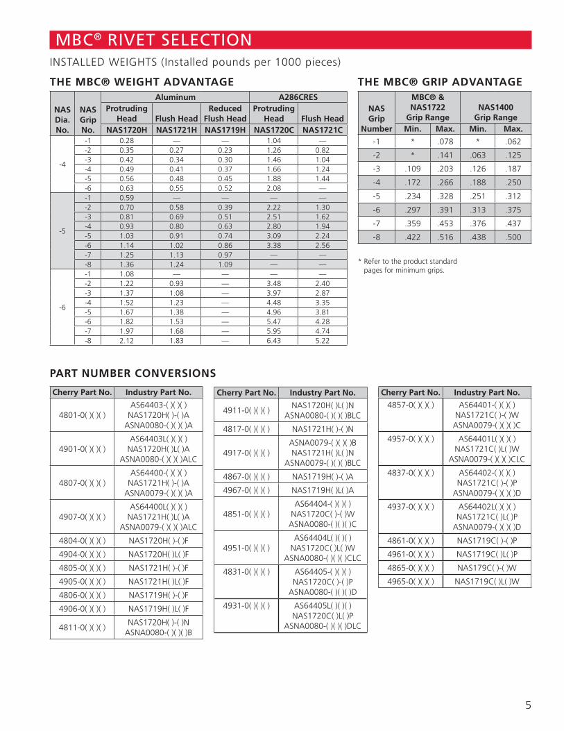
THE MBC® WEIGHT ADVANTAGE
NASDia.No.
NASGripNo.
Aluminum A286CRESProtruding
Head Flush HeadReduced
Flush HeadProtruding
Head Flush HeadNAS1720H NAS1721H NAS1719H NAS1720C NAS1721C
-4
-1 0.28 — — 1.04 —-2 0.35 0.27 0.23 1.26 0.82-3 0.42 0.34 0.30 1.46 1.04-4 0.49 0.41 0.37 1.66 1.24-5 0.56 0.48 0.45 1.88 1.44-6 0.63 0.55 0.52 2.08 —
-5
-1 0.59 — — — —-2 0.70 0.58 0.39 2.22 1.30-3 0.81 0.69 0.51 2.51 1.62-4 0.93 0.80 0.63 2.80 1.94-5 1.03 0.91 0.74 3.09 2.24-6 1.14 1.02 0.86 3.38 2.56-7 1.25 1.13 0.97 — —-8 1.36 1.24 1.09 — —
-6
-1 1.08 — — — —-2 1.22 0.93 — 3.48 2.40-3 1.37 1.08 — 3.97 2.87-4 1.52 1.23 — 4.48 3.35-5 1.67 1.38 — 4.96 3.81-6 1.82 1.53 — 5.47 4.28-7 1.97 1.68 — 5.95 4.74-8 2.12 1.83 — 6.43 5.22
THE MBC® GRIP ADVANTAGE
NASGrip
Number
MBC® & NAS1722
Grip RangeNAS1400
Grip RangeMin. Max. Min. Max.
-1 * .078 * .062
-2 * .141 .063 .125
-3 .109 .203 .126 .187
-4 .172 .266 .188 .250
-5 .234 .328 .251 .312
-6 .297 .391 .313 .375
-7 .359 .453 .376 .437
-8 .422 .516 .438 .500
* Refer to the product standard pages for minimum grips.
MBC® RIVET SELECTIONINSTALLED WEIGHTS (Installed pounds per 1000 pieces)
PART NUMBER CONVERSIONS
Cherry Part No. Industry Part No.
4801-0( )( )( )AS64403-( )( )( )
NAS1720H( )-( )AASNA0080-( )( )( )A
4901-0( )( )( )AS64403L( )( )( )
NAS1720H( )L( )AASNA0080-( )( )( )ALC
4807-0( )( )( )AS64400-( )( )( )
NAS1721H( )-( )AASNA0079-( )( )( )A
4907-0( )( )( )AS64400L( )( )( )
NAS1721H( )L( )AASNA0079-( )( )( )ALC
4804-0( )( )( ) NAS1720H( )-( )F
4904-0( )( )( ) NAS1720H( )L( )F
4805-0( )( )( ) NAS1721H( )-( )F
4905-0( )( )( ) NAS1721H( )L( )F
4806-0( )( )( ) NAS1719H( )-( )F
4906-0( )( )( ) NAS1719H( )L( )F
4811-0( )( )( )NAS1720H( )-( )N
ASNA0080-( )( )( )B
Cherry Part No. Industry Part No.
4911-0( )( )( )NAS1720H( )L( )N
ASNA0080-( )( )( )BLC
4817-0( )( )( ) NAS1721H( )-( )N
4917-0( )( )( )ASNA0079-( )( )( )BNAS1721H( )L( )N
ASNA0079-( )( )( )BLC
4867-0( )( )( ) NAS1719H( )-( )A
4967-0( )( )( ) NAS1719H( )L( )A
4851-0( )( )( )AS64404-( )( )( )
NAS1720C( )-( )WASNA0080-( )( )( )C
4951-0( )( )( )AS64404L( )( )( )
NAS1720C( )L( )WASNA0080-( )( )( )CLC
4831-0( )( )( ) AS64405-( )( )( )NAS1720C( )-( )P
ASNA0080-( )( )( )D
4931-0( )( )( ) AS64405L( )( )( )NAS1720C( )L( )P
ASNA0080-( )( )( )DLC
Cherry Part No. Industry Part No.
4857-0( )( )( ) AS64401-( )( )( )NAS1721C( )-( )W
ASNA0079-( )( )( )C
4957-0( )( )( ) AS64401L( )( )( )NAS1721C( )L( )W
ASNA0079-( )( )( )CLC
4837-0( )( )( ) AS64402-( )( )( )NAS1721C( )-( )P
ASNA0079-( )( )( )D
4937-0( )( )( ) AS64402L( )( )( )NAS1721C( )L( )P
ASNA0079-( )( )( )D
4861-0( )( )( ) NAS1719C( )-( )P
4961-0( )( )( ) NAS1719C( )L( )P
4865-0( )( )( ) NAS179C( )-( )W
4965-0( )( )( ) NAS1719C( )L( )W
5
JDia.After
Installation
Grip for dimpled sheets. The grip length is measured over the dimple.
C Dia.
T Min. Blind Clearance
M L Grip
S*
A Dia.BeforeInstallation
D
P
B Dia.
101° 99° forming anvil is
gold color to identify nominal diameter rivet
CherryManufacturing
Symbol
Material Code: – no letter for
2014A aluminum – C for A-286
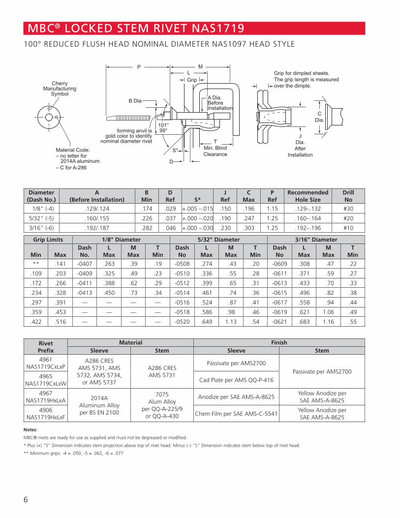
Diameter(Dash No.)
A(Before Installation)
BMin
DRef S*
JRef
CMax
PRef
RecommendedHole Size
DrillNo
1/8" (-4) .129/.124 .174 .029 +.005 –.015 .150 .196 1.15 .129–.132 #30
5/32" (-5) .160/.155 .226 .037 +.000 –.020 .190 .247 1.25 .160–.164 #20
3/16" (-6) .192/.187 .282 .046 +.000 –.030 .230 .303 1.25 .192–.196 #10
Grip Limits 1/8" Diameter 5/32" Diameter 3/16" Diameter
Min MaxDashNo.
LMax
MMax
TMin
DashNo
LMax
MMax
TMin
DashNo
LMax
MMax
TMin
** .141 -0407 .263 .39 .19 -0508 .274 .43 .20 -0609 .308 .47 .22
.109 .203 -0409 .325 .49 .23 -0510 .336 .55 .28 -0611 .371 .59 .27
.172 .266 -0411 .388 .62 .29 -0512 .399 .65 .31 -0613 .433 .70 .33
.234 .328 -0413 .450 .73 .34 -0514 .461 .74 .36 -0615 .496 .82 .38
.297 .391 — — — — -0516 .524 .87 .41 -0617 .558 .94 .44
.359 .453 — — — — -0518 .586 .98 .46 -0619 .621 1.06 .49
.422 .516 — — — — -0520 .649 1.13 .54 -0621 .683 1.16 .55
RivetPrefix
Material FinishSleeve Stem Sleeve Stem
4961NAS1719CxLxP
A286 CRESAMS 5731, AMS 5732, AMS 5734,
or AMS 5737
A286 CRESAMS 5731
Passivate per AMS2700Passivate per AMS2700
4965NAS1719CxLxW
Cad Plate per AMS QQ-P-416
4967NAS1719HxLxA 2014A
Aluminum Alloyper BS EN 2100
7075 Alum Alloy
per QQ-A-225/9 or QQ-A-430
Anodize per SAE AMS-A-8625Yellow Anodize per SAE AMS-A-8625
4906NAS1719HxLxF
Chem Film per SAE AMS-C-5541Yellow Anodize per SAE AMS-A-8625
Notes:
MBC® rivets are ready for use as supplied and must not be degreased or modified.
* Plus (+) “S” Dimension indicates stem projection above top of rivet head. Minus (–) “S” Dimension indicates stem below top of rivet head.
** Minimum grips: -4 = .050, -5 = .062, -6 = .077
MBC® LOCKED STEM RIVET NAS1719100° REDUCED FLUSH HEAD NOMINAL DIAMETER NAS1097 HEAD STYLE
6
J Dia.AfterInstallation
T Min. Blind Clearance
M
L
Grip
S*
A Dia.BeforeInstallation
D
P
B Dia.
forming anvil is gold color to identify
nominal diameter rivet
CherryManufacturing
Symbol
Grip Identification
Material Code: – no letter for 2014A aluminum – C for A-286
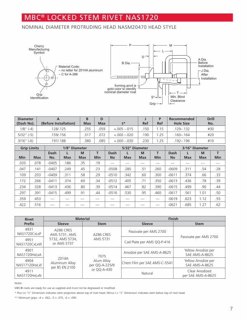
MBC® LOCKED STEM RIVET NAS1720NOMINAL DIAMETER PROTRUDING HEAD NASM20470 HEAD STYLE
Diameter(Dash No).
A(Before Installation)
BMax
DMax S*
JRef
PRef
RecommendedHole Size
DrillNo.
1/8" (-4) .128/.125 .255 .059 +.005 –.015 .150 1.15 .129–.132 #30
5/32" (-5) .159/.156 .317 .072 +.000 –.020 .190 1.25 .160–.164 #20
3/16" (-6) .191/.188 .380 .085 +.000 –.030 .230 1.25 .192–.196 #10
Grip Limits 1/8" Diameter 5/32" Diameter 3/16" Diameter
Min MaxDashNo.
LMax
MMax
TMin
DashNo
LMax
MMax
TMin
DashNo
LMax
MMax
TMin
.020 .078 -0405 .186 .35 .19 — — — — — — — —
.047 .141 -0407 .249 .45 .23 -0508 .280 .51 .260 -0609 .311 .54 .28
.109 .203 -0409 .311 .58 .29 -0510 .342 .60 .300 -0611 .374 .66 .33
.172 .266 -0411 .374 .69 .34 -0512 .405 .71 .350 -0613 .436 .78 .39
.234 .328 -0413 .436 .80 .39 -0514 .467 .82 .390 -0615 .499 .90 .44
.297 .391 -0415 .499 .91 .44 -0516 .530 .95 .460 -0617 .561 1.01 .50
.359 .453 — — — — — — — — -0619 .623 1.12 .55
.422 .516 — — — — — — — — -0621 .685 1.27 .62
RivetPrefix
Material FinishSleeve Stem Sleeve Stem
4931NAS1720CxLxP
A286 CRESAMS 5731, AMS 5732, AMS 5734,
or AMS 5737
A286 CRESAMS 5731
Passivate per AMS 2700Passivate per AMS 2700
4951NAS1720CxLxW
Cad Plate per AMS QQ-P-416
4901NAS1720HxLxA
2014A Aluminum Alloyper BS EN 2100
7075 Alum Alloy
per QQ-A-225/9 or QQ-A-430
Anodize per SAE AMS-A-8625Yellow Anodize per SAE AMS-A-8625
4904NAS17120HxLxF
Chem Film per SAE AMS-C-5541Yellow Anodize per SAE AMS-A-8625
4911NAS1720HxLxN
NaturalClear Anodized
per SAE AMS-A-8625
Notes:
MBC® rivets are ready for use as supplied and must not be degreased or modified.
* Plus (+) “S” Dimension indicates stem projection above top of rivet head. Minus (–) “S” Dimension indicates stem below top of rivet head.
** Minimum grips: -4 = .062, -5 = .075, -6 = .090
7
JDia.After
Installation
Grip for dimpled sheets. The grip length is measured over the dimple.
C Dia.
T Min. Blind Clearance
M L Grip
S*
A Dia.BeforeInstallation
D
P
B Dia.
101° 99° forming anvil is
gold color to identify nominal diameter rivet
CherryManufacturing
Symbol
Material Code: – no letter for
2014A aluminum – C for A-286
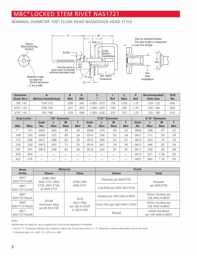
MBC® LOCKED STEM RIVET NAS1721NOMINAL DIAMETER 100° FLUSH HEAD NASM20426 HEAD STYLE
Diameter(Dash No.)
A(Before Installation)
BMin
DRef
S *
JRef
CMax
PRef
RecommendedHole Size
DrillNo
1/8" (-4) .128/.125 .208 .041 +.005 –.015 .150 .229 1.15 .129–.132 #30
5/32" (-5) .159/.156 .267 .053 +.000 –.020 .190 .290 1.25 .160–.164 #20
3/16" (-6) .191/.188 .329 .068 +.000 –.030 .230 .357 1.25 .192–.196 #10
Grip Limits 1/8" Diameter 5/32" Diameter 3/16" Diameter
Min MaxDashNo.
LMax
MMax
TMin
DashNo
LMax
MMax
TMin
DashNo
LMax
MMax
TMin
** .141 -0407 .263 .39 .20 -0508 .274 .43 .20 -0609 .308 .47 .22
.109 .203 -0409 .325 .49 .24 -0510 .336 .55 .28 -0611 .371 .59 .28
.172 .266 -0411 .388 .62 .30 -0512 .399 .65 .31 -0613 .433 .70 .33
.234 .328 -0413 .450 .73 .35 -0514 .461 .76 .36 -0615 .496 .82 .39
.297 .391 -0415 .508 .84 .39 -0516 .524 .87 .41 -0617 .558 .94 .44
.359 .453 — — — — — — — — -0619 .621 1.06 .50
.422 .516 — — — — — — — — -0621 .683 1.16 .55
RivetPrefix
Material FinishSleeve Stem Sleeve Stem
4937NAS1721CxLxP
A286 CRESAMS 5731, AMS 5732, AMS 5734,
or AMS 5737
A286 CRESAMS 5731
Passivate per AMS2700Passivate
per AMS27004957NAS1721CxLxW
Cad Plate per AMS QQ-P-416
4907NAS1721HxLxA
2014A Aluminum Alloyper BS EN 2100
7075 Alum Alloy
per QQ-A-225/9 or QQ-A-430
Anodize per SAE AMS-A-8625Yellow Anodize per SAE AMS-A-8625
4905NAS17121HxLxF
Chem Film per SAE AMS-C-5541Yellow Anodize per SAE AMS-A-8625
4917NAS1721HxLxN
NaturalYellow Anodized
per SAE AMS-A-8625
Notes:
MBC® rivets are ready for use as supplied and must not be degreased or modified.
* Plus (+) “S” Dimension indicates stem projection above top of rivet head. Minus (–) “S” Dimension indicates stem below top of rivet head.
** Minimum grips: -4 = .062, -5 = .075, -6 = .090
8
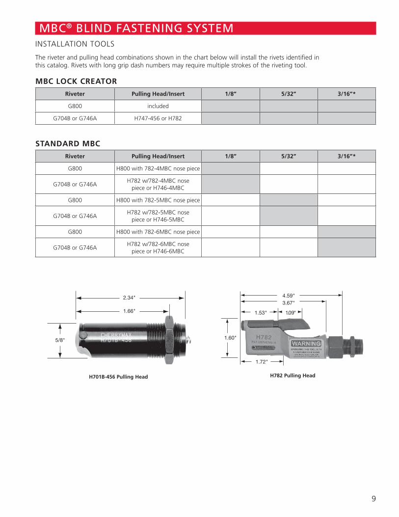
The riveter and pulling head combinations shown in the chart below will install the rivets identified in this catalog. Rivets with long grip dash numbers may require multiple strokes of the riveting tool.
MBC LOCK CREATOR
Riveter Pulling Head/Insert 1/8” 5/32” 3/16”*
G800 included
G704B or G746A H747-456 or H782
STANDARD MBC
Riveter Pulling Head/Insert 1/8” 5/32” 3/16”*
G800 H800 with 782-4MBC nose piece
G704B or G746AH782 w/782-4MBC nose
piece or H746-4MBC
G800 H800 with 782-5MBC nose piece
G704B or G746AH782 w/782-5MBC nose
piece or H746-5MBC
G800 H800 with 782-6MBC nose piece
G704B or G746AH782 w/782-6MBC nose
piece or H746-6MBC
MBC® BLIND FASTENING SYSTEMINSTALLATION TOOLS
2.34"
1.66"
5/8"
H701B-456 Pulling Head
4.59"3.67"
1.53"
1.60"
1.09"
1.72"
H782 Pulling Head
9
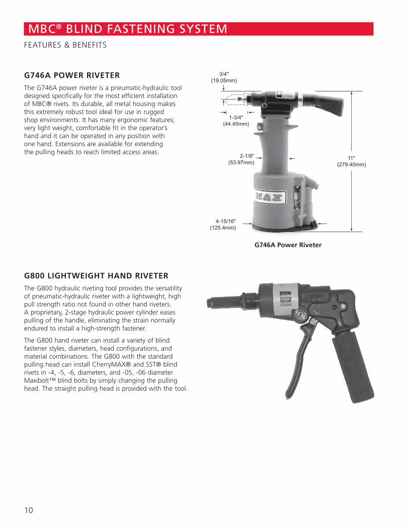
G746A POWER RIVETER
The G746A power riveter is a pneumatic-hydraulic tool designed specifically for the most efficient installation of MBC® rivets. Its durable, all metal housing makes this extremely robust tool ideal for use in rugged shop environments. It has many ergonomic features; very light weight, comfortable fit in the operator’s hand and it can be operated in any position with one hand. Extensions are available for extending the pulling heads to reach limited access areas.
G800 LIGHTWEIGHT HAND RIVETER
The G800 hydraulic riveting tool provides the versatility of pneumatic-hydraulic riveter with a lightweight, high pull strength ratio not found in other hand riveters. A proprietary, 2-stage hydraulic power cylinder eases pulling of the handle, eliminating the strain normally endured to install a high-strength fastener.
The G800 hand riveter can install a variety of blind fastener styles, diameters, head configurations, and material combinations. The G800 with the standard pulling head can install CherryMAX® and SST® blind rivets in -4, -5, -6, diameters, and -05, -06 diameter Maxibolt™ blind bolts by simply changing the pulling head. The straight pulling head is provided with the tool.
G746A Power Riveter
MBC® BLIND FASTENING SYSTEMFEATURES & BENEFITS
10

1224 East Warner Avenue, Santa Ana, CA 92705 voice: 714-545-5511 • fax: 714-850-6093 www.cherryaerospace.com ©2012 Cherry Aerospace Suppliers Federal I.D. Code – 11815 CA-1004, Rev. B, Date: June 25, 2012, DCR 12-0620
SPS Fastener Division, a PCC Company