Embed Size (px)
Citation preview
May 2007
France Telecom - IHPSlide 1
doc.: IEEE 802.15-07-0688-01-003c
Submission
Project: IEEE P802.15 Working Group for Wireless Personal Area NProject: IEEE P802.15 Working Group for Wireless Personal Area Networks (etworks (WPANsWPANs))
Submission Title: [France Telecom - IHP Joint Physical Layer Proposal for IEEE 802.15 Task Group 3c]
Date Submitted: [7 May 2007]
Source: [ Pascal Pagani1, Maxim Piz2,
Isabelle Siaud1, Eckhard Grass2,
Wei Li1, Klaus Tittelbach-Helmrich2 ,
Anne-Marie Ulmer-Moll1, Frank Herzel2]
Company [1 France Telecom, 2 IHP]
Address [see contributors list.]
Voice: [], Fax: [], E-Mail: []
Re: []
Abstract: [Proposition of a high data rate wireless system in the 60 GHz range, providing data rates
ranging from 335 Mbps to 3 Gbps.]
Purpose: []
Notice: This document has been prepared to assist the IEEE P802.15. It is offered as a basis for
discussion and is not binding on the contributing individual(s) or organization(s). The material in this
document is subject to change in form and content after further study. The contributor(s) reserve(s) the
right to add, amend or withdraw material contained herein.
Release: The contributor acknowledges and accepts that this contribution becomes the property of IEEE
and may be made publicly available by P802.15.
May 2007
France Telecom - IHPSlide 2
doc.: IEEE 802.15-07-0688-01-003c
Submission
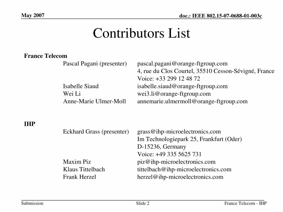
Contributors List
France Telecom
Pascal Pagani (presenter) [email protected]
4, rue du Clos Courtel, 35510 Cesson-Sévigné, France
Voice: +33 299 12 48 72
Isabelle Siaud [email protected]
Wei Li [email protected]
Anne-Marie Ulmer-Moll [email protected]
IHP
Eckhard Grass (presenter) [email protected]
Im Technologiepark 25, Frankfurt (Oder)
D-15236, Germany
Voice: +49 335 5625 731
Maxim Piz [email protected]
Klaus Tittelbach [email protected]
Frank Herzel [email protected]
May 2007
France Telecom - IHPSlide 3
doc.: IEEE 802.15-07-0688-01-003c
Submission
Overview
• Proposal for high data rate, 60 GHz PHY layer for 802.15.3 MAC
• Main features
– Data rates from 335 Mbps to 3 Gbps for applications such as video streaming, file transfer, home network distribution or in-vehicle media supply
– Efficient channelization adapted to worldwide regulation
– OFDM based system providing high spectrum efficiency
– Scalable parameters for increased robustness
– Low power and cost-effective implementation
May 2007
France Telecom - IHPSlide 4
doc.: IEEE 802.15-07-0688-01-003c
Submission
Applications and Frequency Band Plan
May 2007
France Telecom - IHPSlide 5
doc.: IEEE 802.15-07-0688-01-003c
Submission
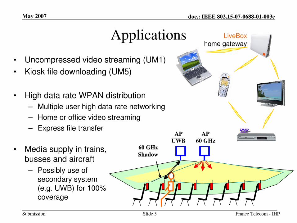
Applications
• Uncompressed video streaming (UM1)
• Kiosk file downloading (UM5)
• High data rate WPAN distribution
– Multiple user high data rate networking
– Home or office video streaming
– Express file transfer
LiveBox
home gateway
AP
UWB
AP
60 GHz 60 GHz
Shadow • Media supply in trains,
busses and aircraft
– Possibly use of secondary system (e.g. UWB) for 100% coverage
May 2007
France Telecom - IHPSlide 6
doc.: IEEE 802.15-07-0688-01-003c
Submission
Applications
• Environments
– Indoor environments (Residential / Office / Library)
– Hot spots
– Confined environments (train, aircraft, …)
– Potential nomadic mode within coverage area
• Cell mode coverage
– Envisioned usage requires radio coverage within one (or more) cell
– Antennas with wide beamwidth are preferred (30°to 60°beamwidth)
– Robust modulation scheme required to deal with channel distortion and related ISI � solution based on OFDM
May 2007
France Telecom - IHPSlide 7
doc.: IEEE 802.15-07-0688-01-003c
Submission
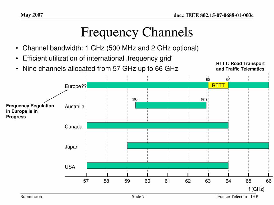
57 58 59 60 61 62 63 64 65 66
Australia
Canada
Japan
USA
59.4 62.9
f [GHz]
Europe??
63 64
RTTT
• Channel bandwidth: 1 GHz (500 MHz and 2 GHz optional)
• Efficient utilization of international ‚frequency grid‘
• Nine channels allocated from 57 GHz up to 66 GHz
Frequency Channels
RTTT: Road Transport and Traffic Telematics
Frequency Regulation in Europe is in Progress
May 2007
France Telecom - IHPSlide 8
doc.: IEEE 802.15-07-0688-01-003c
Submission
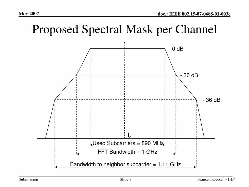
Proposed Spectral Mask per Channel
fc
FFT Bandwidth = 1 GHz
Used Subcarriers = 890 MHz
- 30 dB
- 36 dB
Bandwidth to neighbor subcarrier = 1.11 GHz
0 dB
May 2007
France Telecom - IHPSlide 9
doc.: IEEE 802.15-07-0688-01-003c
Submission
System Architecture
May 2007
France Telecom - IHPSlide 10
doc.: IEEE 802.15-07-0688-01-003c
Submission
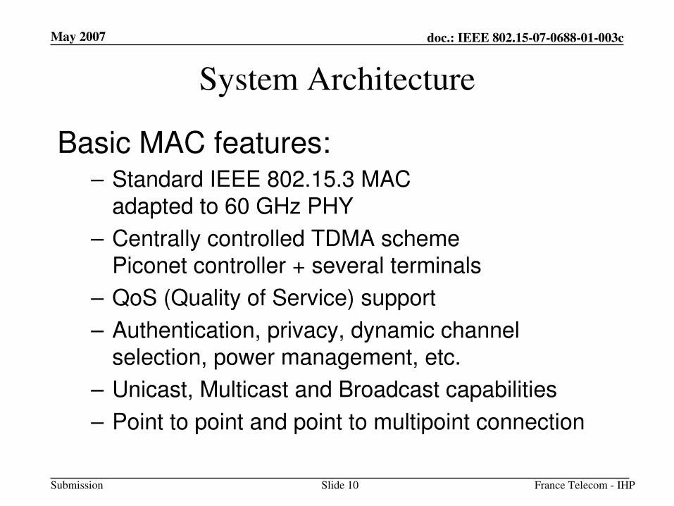
System Architecture
Basic MAC features:– Standard IEEE 802.15.3 MAC
adapted to 60 GHz PHY
– Centrally controlled TDMA schemePiconet controller + several terminals
– QoS (Quality of Service) support
– Authentication, privacy, dynamic channel selection, power management, etc.
– Unicast, Multicast and Broadcast capabilities
– Point to point and point to multipoint connection
May 2007
France Telecom - IHPSlide 11
doc.: IEEE 802.15-07-0688-01-003c
Submission
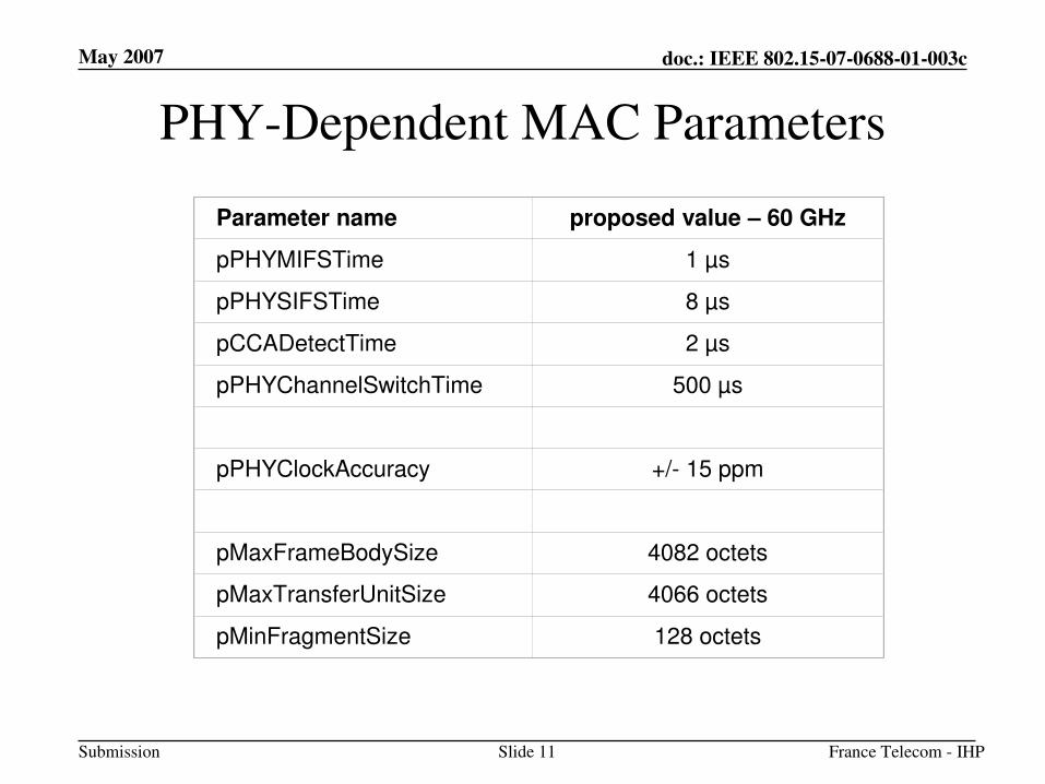
PHY-Dependent MAC Parameters
Parameter name proposed value – 60 GHz
pPHYMIFSTime 1 µs
pPHYSIFSTime 8 µs
pCCADetectTime 2 µs
pPHYChannelSwitchTime 500 µs
pPHYClockAccuracy +/- 15 ppm
pMaxFrameBodySize 4082 octets
pMaxTransferUnitSize 4066 octets
pMinFragmentSize 128 octets
May 2007
France Telecom - IHPSlide 12
doc.: IEEE 802.15-07-0688-01-003c
Submission
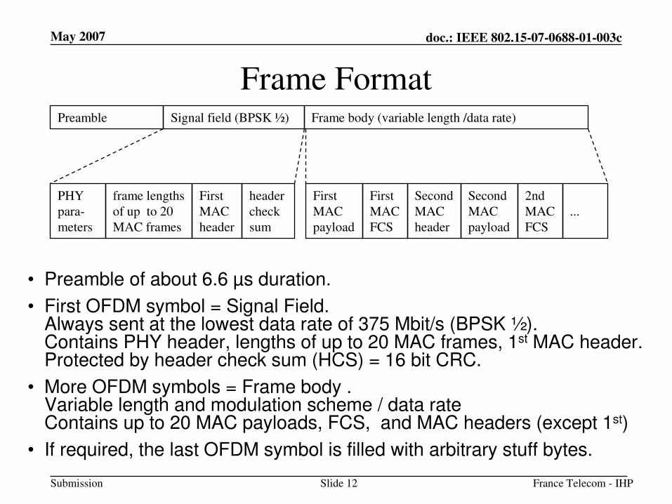
Frame Format
• Preamble of about 6.6 µs duration.
• First OFDM symbol = Signal Field. Always sent at the lowest data rate of 375 Mbit/s (BPSK ½). Contains PHY header, lengths of up to 20 MAC frames, 1st MAC header.Protected by header check sum (HCS) = 16 bit CRC.
• More OFDM symbols = Frame body . Variable length and modulation scheme / data rateContains up to 20 MAC payloads, FCS, and MAC headers (except 1st)
• If required, the last OFDM symbol is filled with arbitrary stuff bytes.
Preamble Signal field (BPSK ½) Frame body (variable length /data rate)
PHY
para-
meters
frame lengths
of up to 20
MAC frames
First
MAC
header
header
check
sum
First
MAC
payload
First
MAC
FCS
Second
MAC
header
Second
MAC
payload
2nd
MAC
FCS
...
May 2007
France Telecom - IHPSlide 13
doc.: IEEE 802.15-07-0688-01-003c
Submission
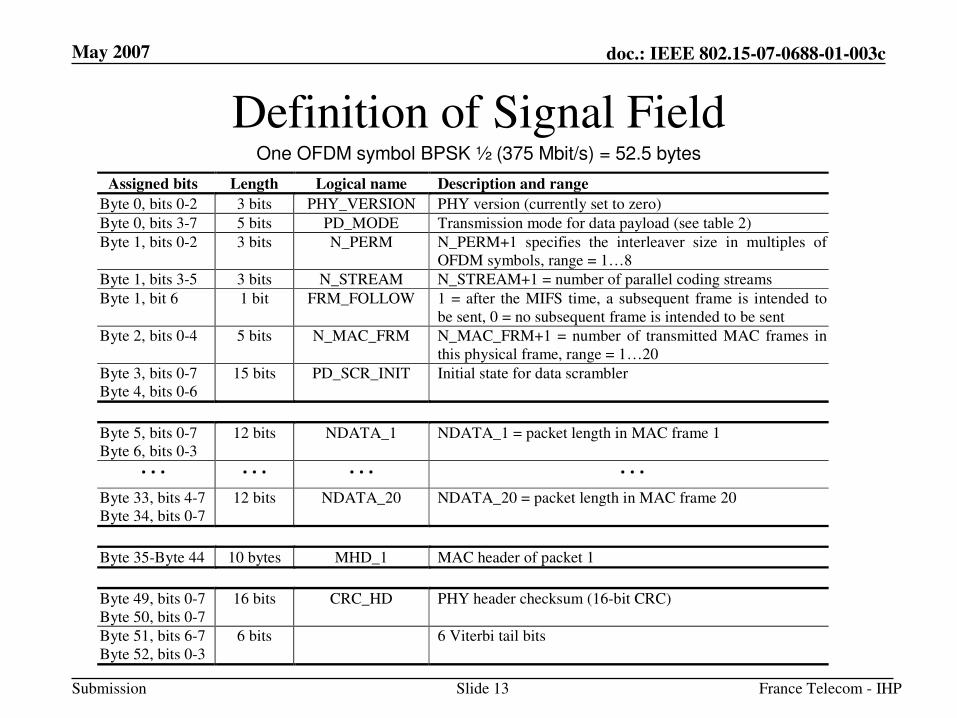
Definition of Signal FieldOne OFDM symbol BPSK ½ (375 Mbit/s) = 52.5 bytes
Assigned bits Length Logical name Description and range
Byte 0, bits 0-2 3 bits PHY_VERSION PHY version (currently set to zero)
Byte 0, bits 3-7 5 bits PD_MODE Transmission mode for data payload (see table 2)
Byte 1, bits 0-2 3 bits N_PERM N_PERM+1 specifies the interleaver size in multiples of
OFDM symbols, range = 1…8
Byte 1, bits 3-5 3 bits N_STREAM N_STREAM+1 = number of parallel coding streams
Byte 1, bit 6 1 bit FRM_FOLLOW 1 = after the MIFS time, a subsequent frame is intended to
be sent, 0 = no subsequent frame is intended to be sent
Byte 2, bits 0-4 5 bits N_MAC_FRM N_MAC_FRM+1 = number of transmitted MAC frames in
this physical frame, range = 1…20
Byte 3, bits 0-7
Byte 4, bits 0-6
15 bits PD_SCR_INIT Initial state for data scrambler
Byte 5, bits 0-7
Byte 6, bits 0-3
12 bits NDATA_1 NDATA_1 = packet length in MAC frame 1
· · · · · · · · · · · ·
Byte 33, bits 4-7
Byte 34, bits 0-7
12 bits NDATA_20 NDATA_20 = packet length in MAC frame 20
Byte 35-Byte 44 10 bytes MHD_1 MAC header of packet 1
Byte 49, bits 0-7
Byte 50, bits 0-7
16 bits CRC_HD PHY header checksum (16-bit CRC)
Byte 51, bits 6-7
Byte 52, bits 0-3
6 bits 6 Viterbi tail bits
May 2007
France Telecom - IHPSlide 14
doc.: IEEE 802.15-07-0688-01-003c
Submission
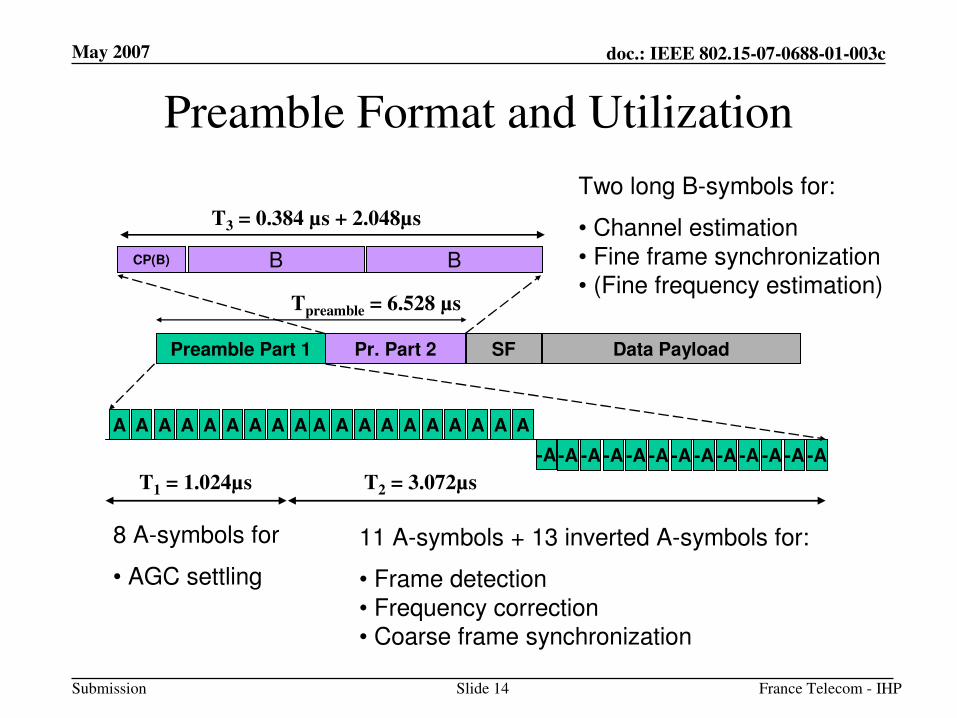
Preamble Format and Utilization
Preamble Part 1 Pr. Part 2 SF Data Payload
A A A A A A A A A A A A A A A A A A
-A -A-A -A -A -A -A -A
8 A-symbols for
• AGC settling
11 A-symbols + 13 inverted A-symbols for:
• Frame detection
• Frequency correction• Coarse frame synchronization
-A -A -A -A
A
-A
T1 = 1.024µs T2 = 3.072µs
CP(B) B B
Two long B-symbols for:
• Channel estimation
• Fine frame synchronization• (Fine frequency estimation)
T3 = 0.384 µs + 2.048µs
Tpreamble = 6.528 µs
May 2007
France Telecom - IHPSlide 15
doc.: IEEE 802.15-07-0688-01-003c
Submission
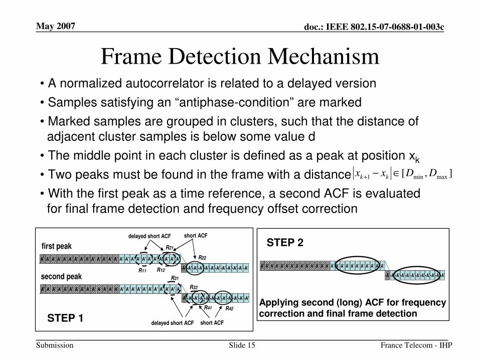
Frame Detection Mechanism
A’ A’ A’ A’ A’ A’ A’ A’ A’ A’ A’ A’ A’ A’ A’ A’ A’ A’ A’ A’ A’ A’ A’ A’
-A’-A’-A’-A’-A’-A’-A’-A’-A’-A’-A’-A’
A’
A’ A’ A’ A’ A’ A’ A’ A’ A’ A’ A’ A’ A’ A’ A’ A’ A’ A’ A’ A’ A’ A’ A’ A’
-A’ -A’-A’-A’-A’ -A’-A’-A’-A’-A’-A’-A’
A’
short ACFdelayed short ACF
short ACFdelayed short ACF
first peak
second peakR11 R12
R31
R21
R22
R32
R41 R42
],[ maxmin1 DDxx kk ∈−+
• A normalized autocorrelator is related to a delayed version
• Samples satisfying an “antiphase-condition” are marked
• Marked samples are grouped in clusters, such that the distance of
adjacent cluster samples is below some value d
• The middle point in each cluster is defined as a peak at position xk
• Two peaks must be found in the frame with a distance
• With the first peak as a time reference, a second ACF is evaluated
for final frame detection and frequency offset correction
A’ A’ A’ A’ A’ A’ A’ A’ A’ A’ A’ A’ A’ A’ A’ A’ A’ A’ A’ A’ A’ A’ A’ A’
-A’-A’-A’-A’-A’-A’-A’-A’-A’-A’-A’-A’
A’
Applying second (long) ACF for frequency correction and final frame detectionSTEP 1
STEP 2
May 2007
France Telecom - IHPSlide 16
doc.: IEEE 802.15-07-0688-01-003c
Submission
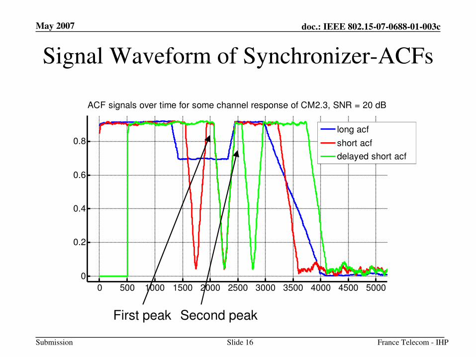
Signal Waveform of Synchronizer-ACFs
0 500 1000 1500 2000 2500 3000 3500 4000 4500 5000
0
0.2
0.4
0.6
0.8
ACF signals over time for some channel response of CM2.3, SNR = 20 dB
long acf
short acf
delayed short acf
First peak Second peak
May 2007
France Telecom - IHPSlide 17
doc.: IEEE 802.15-07-0688-01-003c
Submission
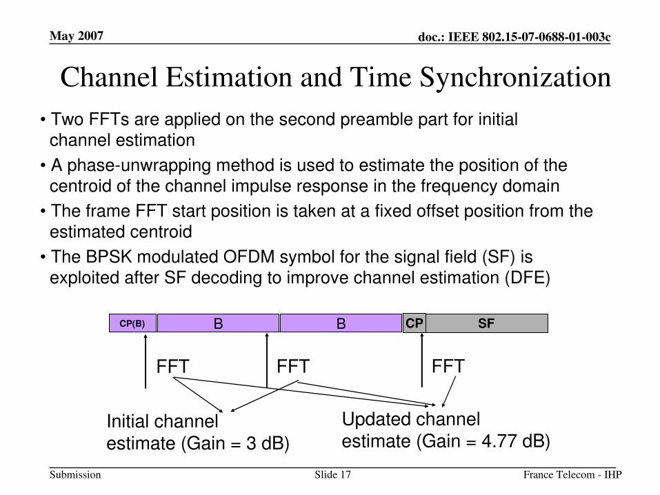
Channel Estimation and Time Synchronization
CP(B) B B
• Two FFTs are applied on the second preamble part for initial channel estimation
• A phase-unwrapping method is used to estimate the position of the centroid of the channel impulse response in the frequency domain
• The frame FFT start position is taken at a fixed offset position from theestimated centroid
• The BPSK modulated OFDM symbol for the signal field (SF) isexploited after SF decoding to improve channel estimation (DFE)
SFCP
FFT FFT FFT
Initial channel estimate (Gain = 3 dB)
Updated channel estimate (Gain = 4.77 dB)
May 2007
France Telecom - IHPSlide 18
doc.: IEEE 802.15-07-0688-01-003c
Submission
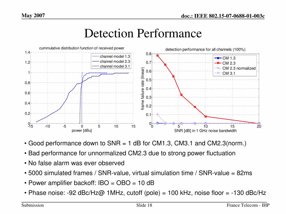
Detection Performance
0 5 10 15 200
0.1
0.2
0.3
0.4
0.5
0.6
0.7
0.8
SNR [dB] in 1 GHz noise bandwidth
fram
e failu
re r
ate
(lin
ear)
detection performance for all channels (100%)
CM 1.3
CM 2.3
CM 2.3 normalized
CM 3.1
-15 -10 -5 0 5 10 150
0.2
0.4
0.6
0.8
1
1.2
1.4
power [dBu]
cummulative distribution function of received power
channel model 1.3
channel model 2.3
channel model 3.1
• Good performance down to SNR = 1 dB for CM1.3, CM3.1 and CM2.3(norm.)
• Bad performance for unnormalized CM2.3 due to strong power fluctuation
• No false alarm was ever observed
• 5000 simulated frames / SNR-value, virtual simulation time / SNR-value = 82ms
• Power amplifier backoff: IBO = OBO = 10 dB
• Phase noise: -92 dBc/Hz@ 1MHz, cutoff (pole) = 100 kHz, noise floor = -130 dBc/Hz
May 2007
France Telecom - IHPSlide 19
doc.: IEEE 802.15-07-0688-01-003c
Submission
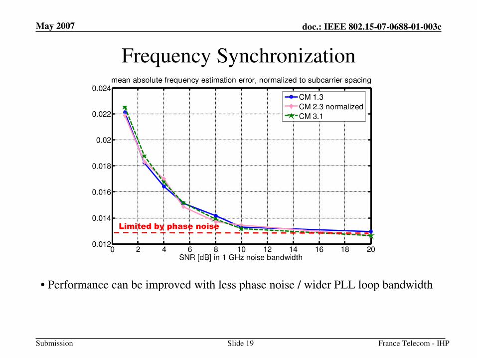
Frequency Synchronization
• Performance can be improved with less phase noise / wider PLL loop bandwidth
0 2 4 6 8 10 12 14 16 18 200.012
0.014
0.016
0.018
0.02
0.022
0.024
SNR [dB] in 1 GHz noise bandwidth
mean absolute frequency estimation error, normalized to subcarrier spacing
CM 1.3
CM 2.3 normalized
CM 3.1
Limited by phase noise
May 2007
France Telecom - IHPSlide 20
doc.: IEEE 802.15-07-0688-01-003c
Submission
PHY Baseband Description
May 2007
France Telecom - IHPSlide 21
doc.: IEEE 802.15-07-0688-01-003c
Submission
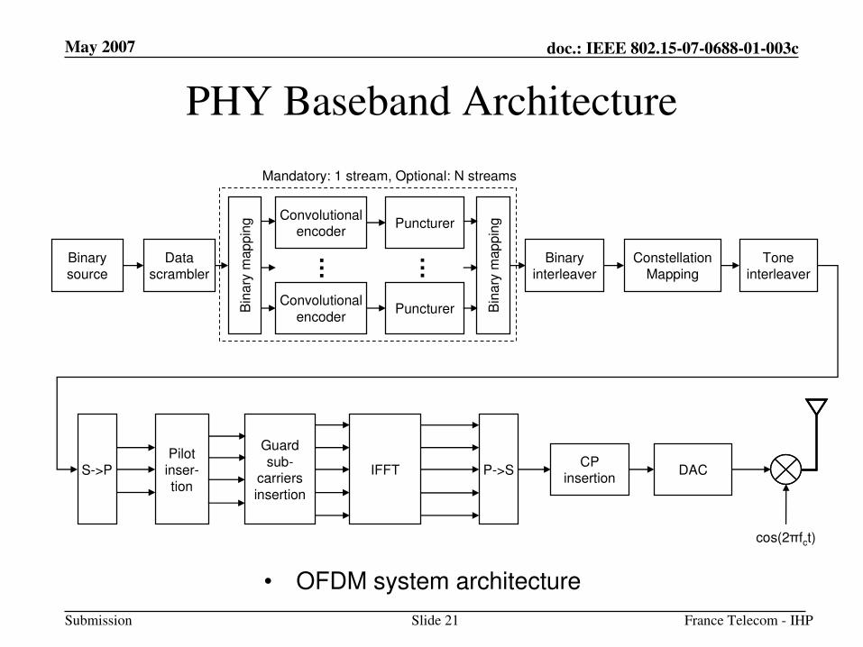
PHY Baseband Architecture
• OFDM system architecture
Binarysource
Data scrambler
Puncturer
Binaryinterleaver
Constellation Mapping
Toneinterleaver
S->PPilot inser-tion
IFFT P->SCP
insertion
cos(2πfct)
DAC
Convolutional
encoder
Guard
sub-carriers
insertion
PuncturerConvolutional
encoderB
ina
rym
ap
pin
g
Bin
ary
map
pin
g
… …
Mandatory: 1 stream, Optional: N streams
May 2007
France Telecom - IHPSlide 22
doc.: IEEE 802.15-07-0688-01-003c
Submission
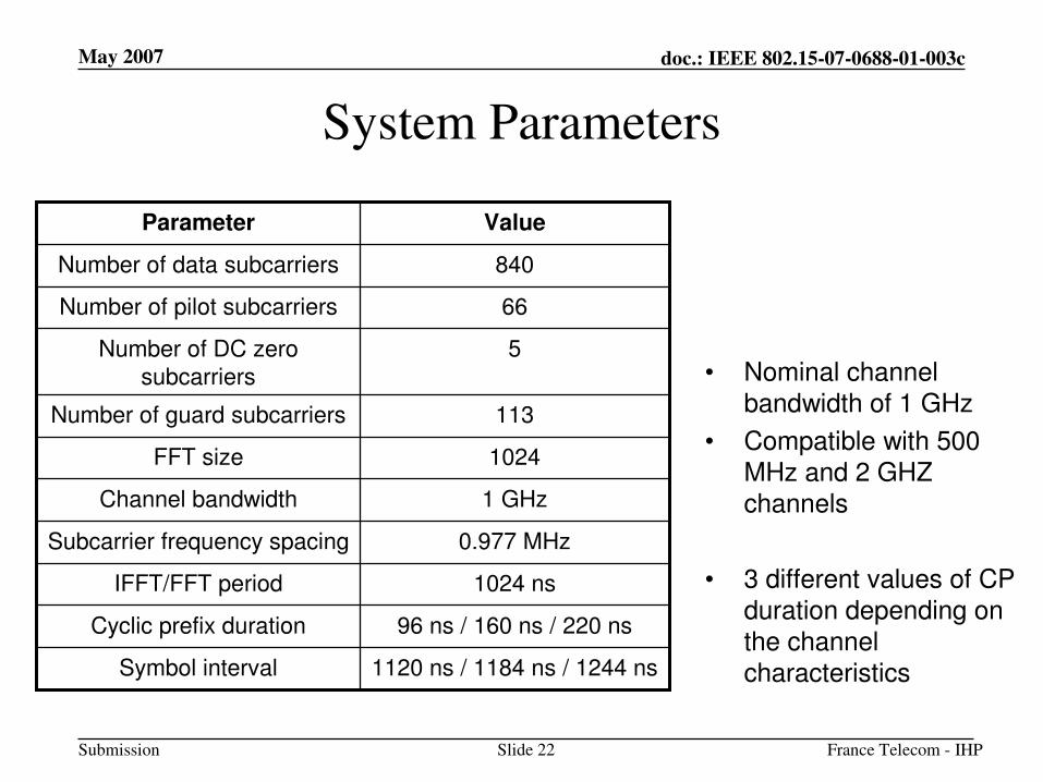
System Parameters
1120 ns / 1184 ns / 1244 nsSymbol interval
96 ns / 160 ns / 220 nsCyclic prefix duration
1024 nsIFFT/FFT period
0.977 MHzSubcarrier frequency spacing
1 GHzChannel bandwidth
1024FFT size
113Number of guard subcarriers
5Number of DC zero
subcarriers
66Number of pilot subcarriers
840Number of data subcarriers
ValueParameter
• Nominal channel bandwidth of 1 GHz
• Compatible with 500 MHz and 2 GHZ channels
• 3 different values of CP duration depending on the channel characteristics
May 2007
France Telecom - IHPSlide 23
doc.: IEEE 802.15-07-0688-01-003c
Submission
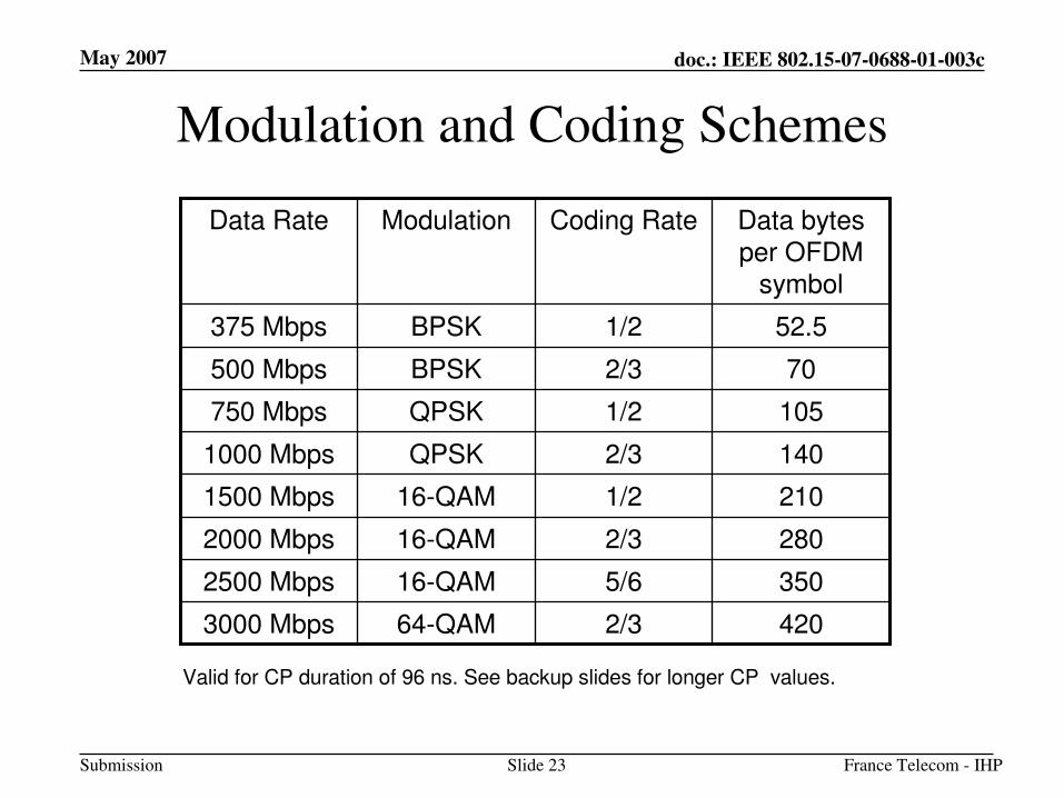
Modulation and Coding Schemes
4202/364-QAM3000 Mbps
3505/616-QAM2500 Mbps
2802/316-QAM2000 Mbps
2101/216-QAM1500 Mbps
1402/3QPSK1000 Mbps
1051/2QPSK750 Mbps
702/3BPSK500 Mbps
52.51/2BPSK375 Mbps
Data bytes per OFDM
symbol
Coding RateModulationData Rate
Valid for CP duration of 96 ns. See backup slides for longer CP values.
May 2007
France Telecom - IHPSlide 24
doc.: IEEE 802.15-07-0688-01-003c
Submission
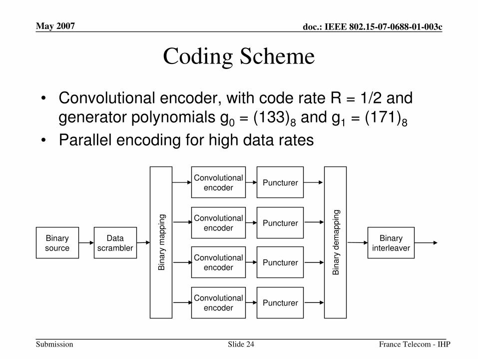
Coding Scheme
• Convolutional encoder, with code rate R = 1/2 and generator polynomials g0 = (133)8 and g1 = (171)8
• Parallel encoding for high data rates
Binary
source
Data
scrambler
Puncturer
Binary
interleaver
Convolutional
encoder
PuncturerConvolutional
encoder
PuncturerConvolutional
encoder
PuncturerConvolutional
encoderBin
ary
mapp
ing
Bin
ary
dem
ap
pin
g
May 2007
France Telecom - IHPSlide 25
doc.: IEEE 802.15-07-0688-01-003c
Submission
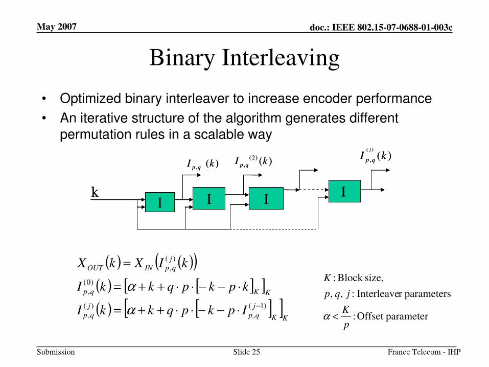
Binary Interleaving
• Optimized binary interleaver to increase encoder performance
• An iterative structure of the algorithm generates different permutation rules in a scalable way
( )
, ( )j
p qI k(2)
, ( )p qI k
I I Ik I
, ( )p qI k
( )
, ( )j
p qI k(2)
, ( )p qI k
I I Ik I
, ( )p qI k
( ) ( )( )
( ) [ ][ ]
( ) [ ][ ]KK
j
qp
j
qp
KKqp
j
qpINOUT
IpkpqkkI
kpkpqkkI
kIXkX
)1(
,
)(
,
)0(
,
)(
,
−⋅−−⋅⋅++=
⋅−−⋅⋅++=
=
α
α
parameterOffset :
parametersr Interleave : , ,
size,Block :
p
K
jqp
K
<α
May 2007
France Telecom - IHPSlide 26
doc.: IEEE 802.15-07-0688-01-003c
Submission
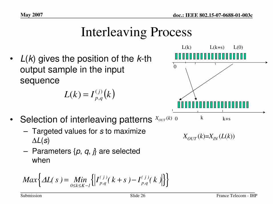
Interleaving Process
• L(k) gives the position of the k-thoutput sample in the input sequence
• Selection of interleaving patterns
– Targeted values for s to maximize
∆L(s)
– Parameters {p, q, j} are selected when
XOUT (k) 0
0
L(0)L(k)
k
L(k+s)
k+s
XOUT (k)=XIN (L(k))
{ }{ }( j ) ( j )
p ,q p ,q0 k K 1
Max L( s ) Min I ( k s ) I ( k )∆≤ ≤ −
= + −
( )kIkLj
qp
)(
,)( =
May 2007
France Telecom - IHPSlide 27
doc.: IEEE 802.15-07-0688-01-003c
Submission
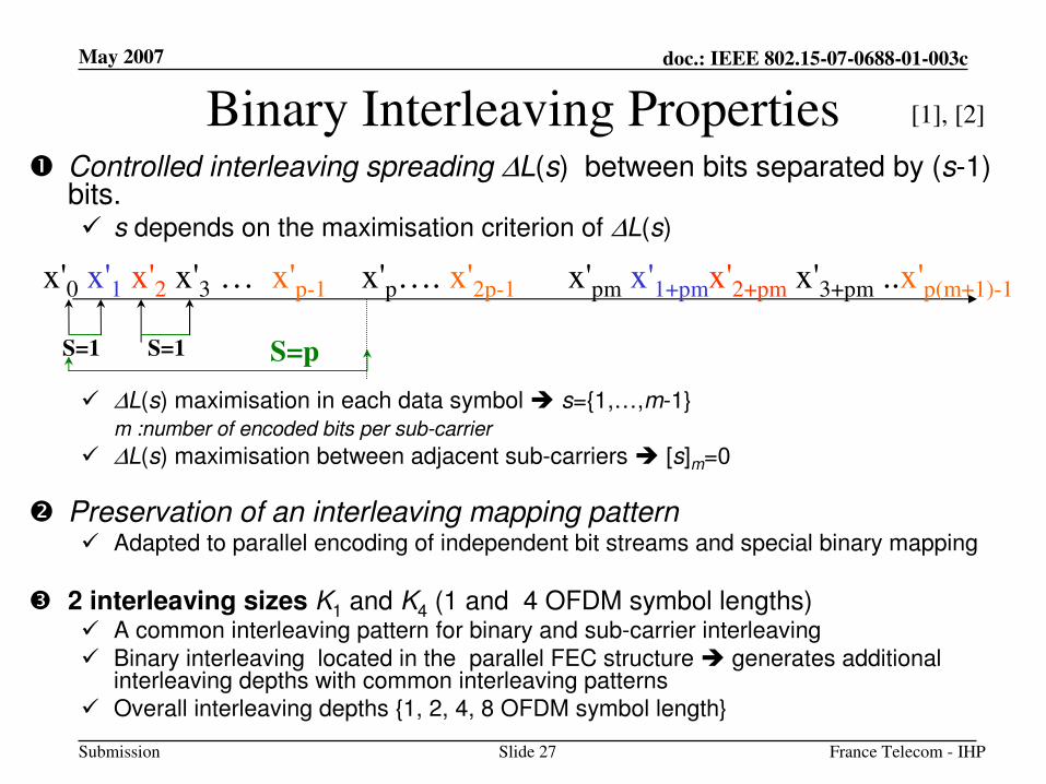
Binary Interleaving Properties� Controlled interleaving spreading ∆L(s) between bits separated by (s-1)
bits. � s depends on the maximisation criterion of ∆L(s)
� ∆L(s) maximisation in each data symbol � s={1,…,m-1}m :number of encoded bits per sub-carrier
� ∆L(s) maximisation between adjacent sub-carriers � [s]m=0
� Preservation of an interleaving mapping pattern� Adapted to parallel encoding of independent bit streams and special binary mapping
� 2 interleaving sizes K1 and K4 (1 and 4 OFDM symbol lengths)� A common interleaving pattern for binary and sub-carrier interleaving
� Binary interleaving located in the parallel FEC structure � generates additional interleaving depths with common interleaving patterns
� Overall interleaving depths {1, 2, 4, 8 OFDM symbol length}
S=1 S=1 S=p
x'0 x'1 x'2 x'3 … x'p-1 x'p…. x'2p-1 x'pm x'1+pmx'2+pm x'3+pm ..x'p(m+1)-1
[1], [2]
May 2007
France Telecom - IHPSlide 28
doc.: IEEE 802.15-07-0688-01-003c
Submission
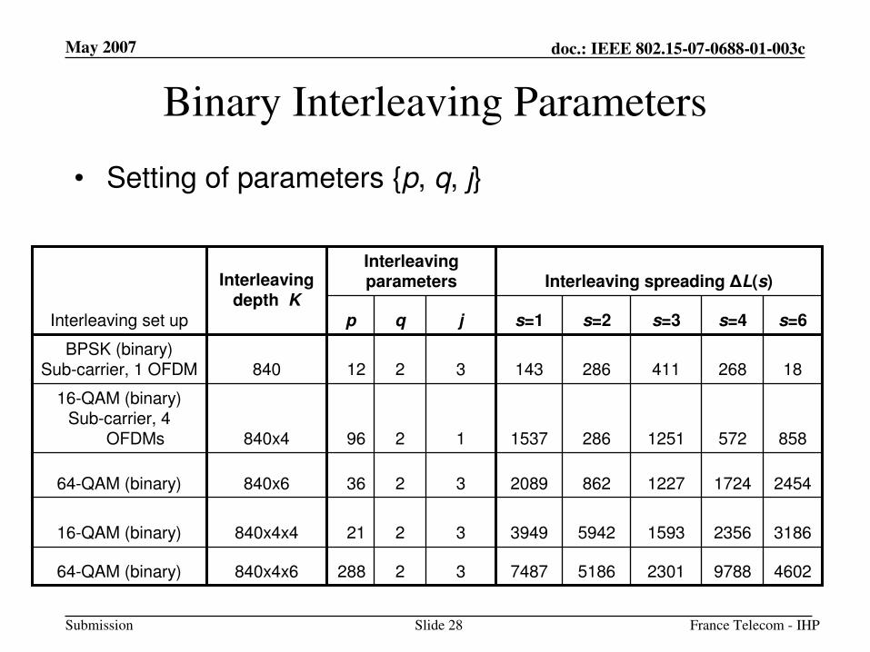
Binary Interleaving Parameters
• Setting of parameters {p, q, j}
Interleaving spreading ∆L(s)InterleavingparametersInterleaving
depth K
858572125128615371296840x4
16-QAM (binary)Sub-carrier, 4
OFDMs
64-QAM (binary)
16-QAM (binary)
64-QAM (binary)
BPSK (binary)Sub-carrier, 1 OFDM
Interleaving set up
4602978823015186748732288840x4x6
318623561593594239493221840x4x4
24541724122786220893236840x6
182684112861433212840
s=6s=4s=3s=2s=1jqp
May 2007
France Telecom - IHPSlide 29
doc.: IEEE 802.15-07-0688-01-003c
Submission
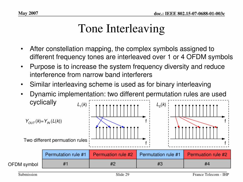
Tone Interleaving
• After constellation mapping, the complex symbols assigned to different frequency tones are interleaved over 1 or 4 OFDM symbols
• Purpose is to increase the system frequency diversity and reduceinterference from narrow band interferers
• Similar interleaving scheme is used as for binary interleaving
• Dynamic implementation: two different permutation rules are usedcyclically
Permutation rule #1 Permuation rule #2 Permutation rule #1 Permuation rule #2
#2#1 #4#3OFDM symbol
Two different permuation rules
f
f
f
f
YOUT (k)=YIN (L(k))
L1(k) L2(k)
May 2007
France Telecom - IHPSlide 30
doc.: IEEE 802.15-07-0688-01-003c
Submission
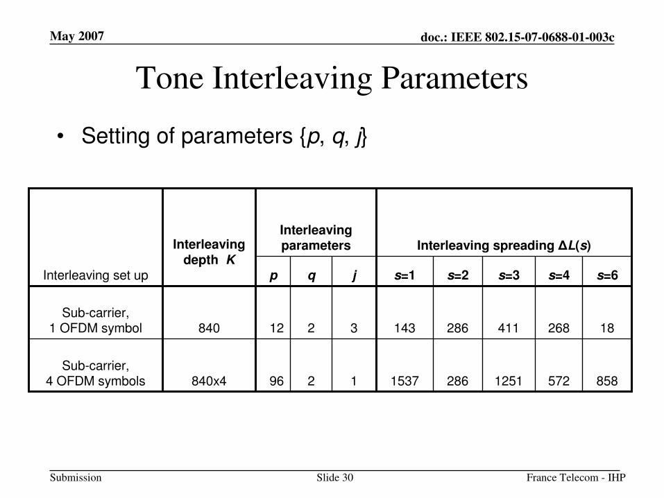
Tone Interleaving Parameters
• Setting of parameters {p, q, j}
Interleaving spreading ∆L(s)InterleavingparametersInterleaving
depth K
858572125128615371296840x4Sub-carrier,
4 OFDM symbols
Sub-carrier,1 OFDM symbol
Interleaving set up
182684112861433212840
s=6s=4s=3s=2s=1jqp
May 2007
France Telecom - IHPSlide 31
doc.: IEEE 802.15-07-0688-01-003c
Submission
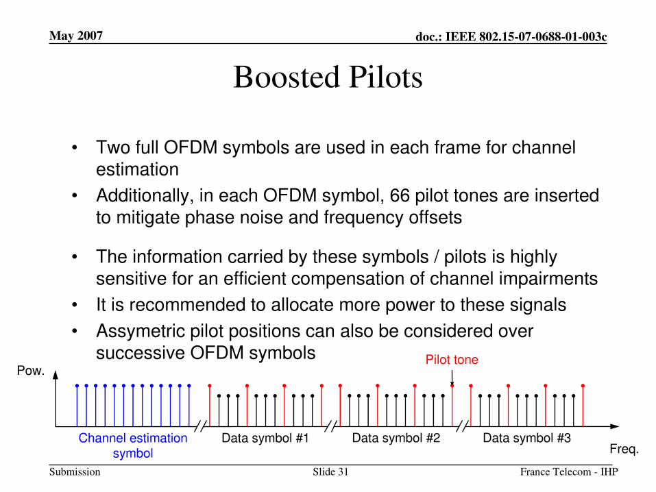
Boosted Pilots
• Two full OFDM symbols are used in each frame for channelestimation
• Additionally, in each OFDM symbol, 66 pilot tones are insertedto mitigate phase noise and frequency offsets
• The information carried by these symbols / pilots is highly sensitive for an efficient compensation of channel impairments
• It is recommended to allocate more power to these signals
• Assymetric pilot positions can also be considered over successive OFDM symbols
Channel estimationsymbol
Data symbol #1 Data symbol #2 Data symbol #3
Pilot tone
Freq.
Pow.
May 2007
France Telecom - IHPSlide 32
doc.: IEEE 802.15-07-0688-01-003c
Submission
System Performance
May 2007
France Telecom - IHPSlide 33
doc.: IEEE 802.15-07-0688-01-003c
Submission
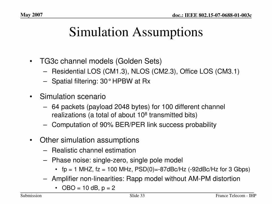
Simulation Assumptions
• TG3c channel models (Golden Sets)
– Residential LOS (CM1.3), NLOS (CM2.3), Office LOS (CM3.1)
– Spatial filtering: 30°HPBW at Rx
• Simulation scenario
– 64 packets (payload 2048 bytes) for 100 different channel realizations (a total of about 108 transmitted bits)
– Computation of 90% BER/PER link success probability
• Other simulation assumptions
– Realistic channel estimation
– Phase noise: single-zero, single pole model
• fp = 1 MHZ, fz = 100 MHz, PSD(0)=-87dBc/Hz (-92dBc/Hz for 3 Gbps)
– Amplifier non-linearities: Rapp model without AM-PM distortion
• OBO = 10 dB, p = 2
May 2007
France Telecom - IHPSlide 34
doc.: IEEE 802.15-07-0688-01-003c
Submission
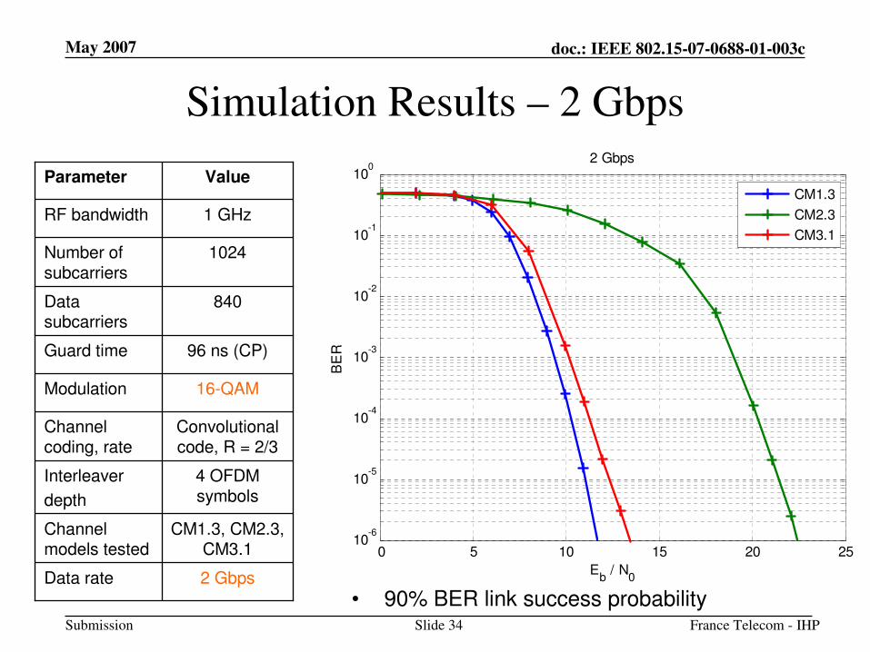
Simulation Results – 2 Gbps
CM1.3, CM2.3, CM3.1
Channel models tested
2 GbpsData rate
4 OFDM symbols
Interleaver
depth
Channel coding, rate
Modulation
Guard time
Data subcarriers
Number of subcarriers
RF bandwidth
Parameter
840
16-QAM
Convolutionalcode, R = 2/3
96 ns (CP)
1024
1 GHz
Value
• 90% BER link success probability
0 5 10 15 20 2510
-6
10-5
10-4
10-3
10-2
10-1
100
BE
R
Eb / N
0
2 Gbps
CM1.3
CM2.3
CM3.1
May 2007
France Telecom - IHPSlide 35
doc.: IEEE 802.15-07-0688-01-003c
Submission
Simulation Results – 2 Gbps
CM1.3, CM2.3, CM3.1
Channel models tested
2 GbpsData rate
4 OFDM symbols
Interleaver
depth
Channel coding, rate
Modulation
Guard time
Data subcarriers
Number of subcarriers
RF bandwidth
Parameter
840
16-QAM
Convolutionalcode, R = 2/3
96 ns (CP)
1024
1 GHz
Value
• 90% PER link success probability
0 5 10 15 20 2510
-2
10-1
100
PE
R
Eb / N
0
2 Gbps
CM1.3
CM2.3
CM3.1
May 2007
France Telecom - IHPSlide 36
doc.: IEEE 802.15-07-0688-01-003c
Submission
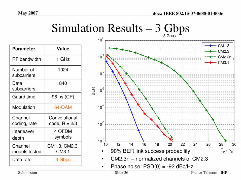
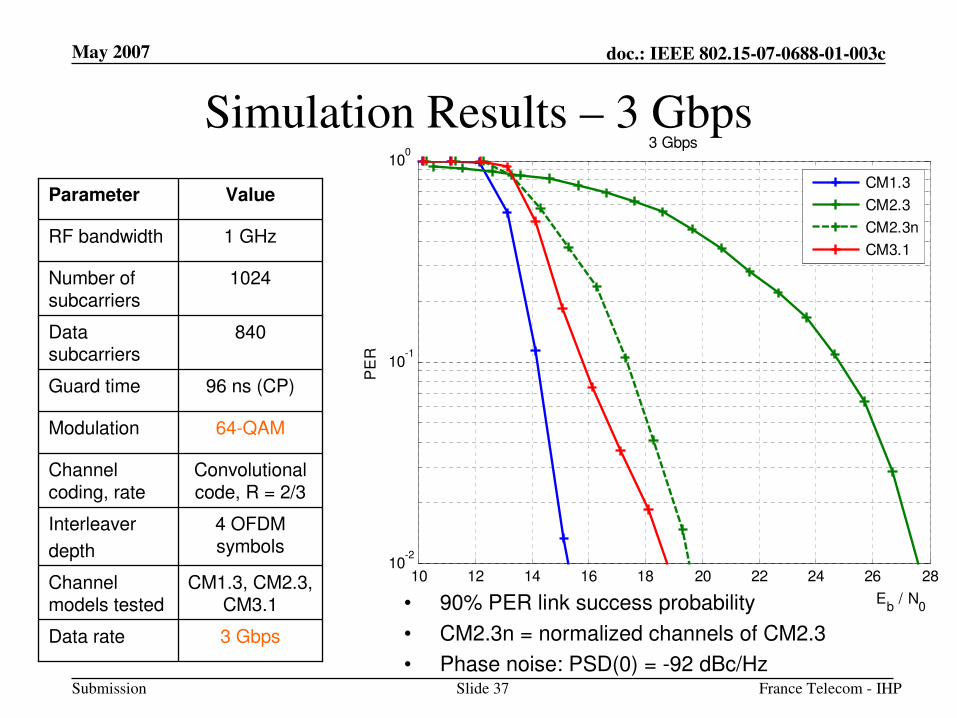
Simulation Results – 3 Gbps
CM1.3, CM2.3, CM3.1
Channel models tested
3 GbpsData rate
4 OFDM symbols
Interleaver
depth
Channel coding, rate
Modulation
Guard time
Data subcarriers
Number of subcarriers
RF bandwidth
Parameter
840
64-QAM
Convolutionalcode, R = 2/3
96 ns (CP)
1024
1 GHz
Value
• 90% BER link success probability
• CM2.3n = normalized channels of CM2.3
• Phase noise: PSD(0) = -92 dBc/Hz
10 12 14 16 18 20 22 24 26 28 3010
-6
10-5
10-4
10-3
10-2
10-1
100
BE
R
Eb / N
0
3 Gbps
CM1.3
CM2.3
CM2.3n
CM3.1
May 2007
France Telecom - IHPSlide 37
doc.: IEEE 802.15-07-0688-01-003c
Submission
Simulation Results – 3 Gbps
CM1.3, CM2.3, CM3.1
Channel models tested
3 GbpsData rate
4 OFDM symbols
Interleaver
depth
Channel coding, rate
Modulation
Guard time
Data subcarriers
Number of subcarriers
RF bandwidth
Parameter
840
64-QAM
Convolutionalcode, R = 2/3
96 ns (CP)
1024
1 GHz
Value
• 90% PER link success probability
• CM2.3n = normalized channels of CM2.3
• Phase noise: PSD(0) = -92 dBc/Hz
10 12 14 16 18 20 22 24 26 2810
-2
10-1
100
PE
R
Eb / N
0
3 Gbps
CM1.3
CM2.3
CM2.3n
CM3.1
May 2007
France Telecom - IHPSlide 38
doc.: IEEE 802.15-07-0688-01-003c
Submission
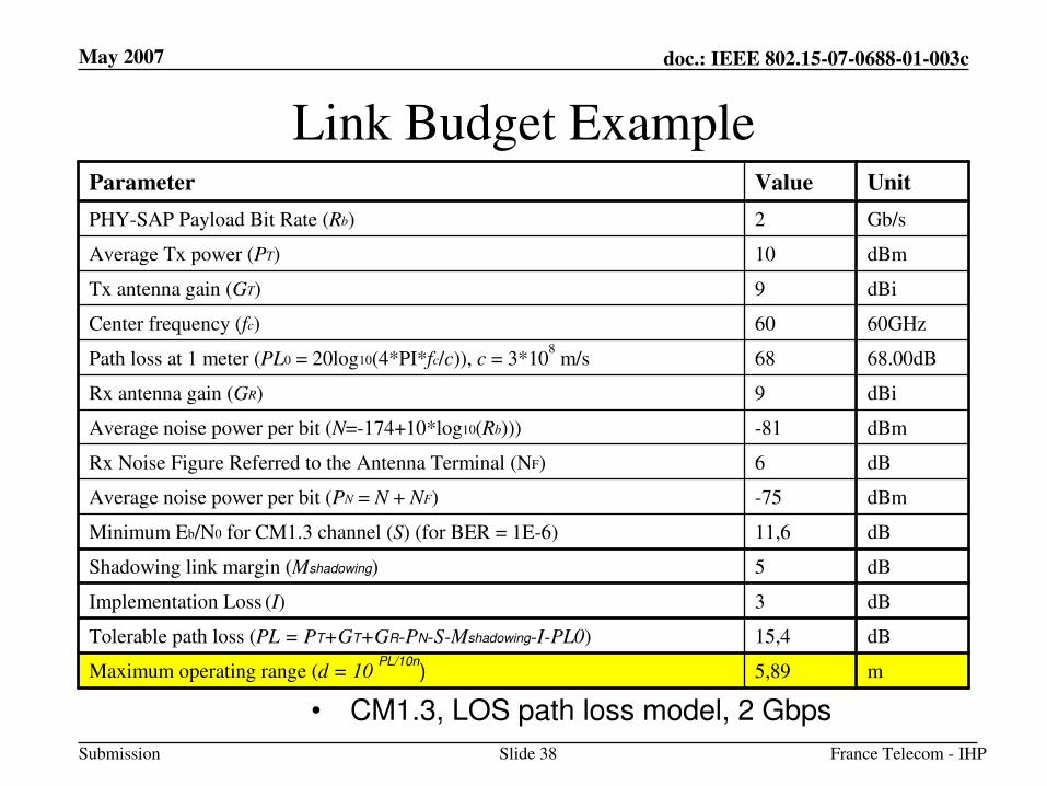
Link Budget Example
• CM1.3, LOS path loss model, 2 Gbps
m5,89Maximum operating range (d = 10 PL/10n
)
dB15,4Tolerable path loss (PL = PT+GT+GR-PN-S-Mshadowing-I-PL0)
dB3Implementation Loss (I)
dB5Shadowing link margin (Mshadowing)
dB11,6Minimum Eb/N0 for CM1.3 channel (S) (for BER = 1E-6)
dBm-75Average noise power per bit (PN = N + NF)
dB6Rx Noise Figure Referred to the Antenna Terminal (NF)
dBm-81Average noise power per bit (N=-174+10*log10(Rb)))
dBi9Rx antenna gain (GR)
68.00dB68Path loss at 1 meter (PL0 = 20log10(4*PI*fc/c)), c = 3*108
m/s
60GHz60Center frequency (fc)
dBi9Tx antenna gain (GT)
dBm10Average Tx power (PT)
Gb/s2PHY-SAP Payload Bit Rate (Rb)
UnitValueParameter
May 2007
France Telecom - IHPSlide 39
doc.: IEEE 802.15-07-0688-01-003c
Submission
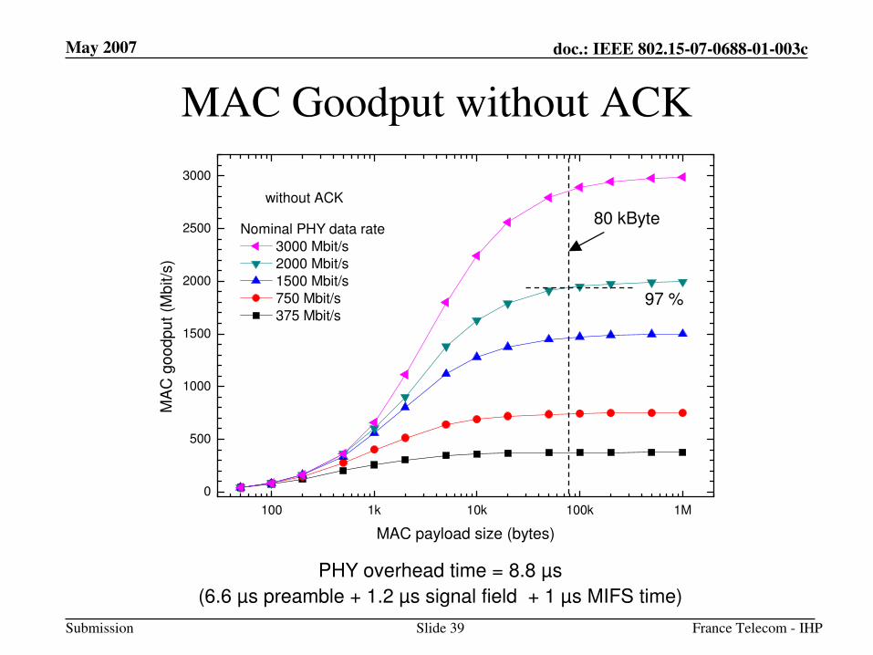
MAC Goodput without ACK
PHY overhead time = 8.8 µs
(6.6 µs preamble + 1.2 µs signal field + 1 µs MIFS time)
100 1k 10k 100k 1M
0
500
1000
1500
2000
2500
3000
without ACK
MA
C g
oo
dp
ut
(Mb
it/s
)
MAC payload size (bytes)
Nominal PHY data rate
3000 Mbit/s
2000 Mbit/s
1500 Mbit/s
750 Mbit/s
375 Mbit/s
80 kByte
97 %
May 2007
France Telecom - IHPSlide 40
doc.: IEEE 802.15-07-0688-01-003c
Submission
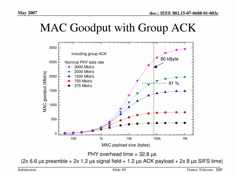
MAC Goodput with Group ACK
PHY overhead time = 32.8 µs
(2x 6.6 µs preamble + 2x 1.2 µs signal field + 1.2 µs ACK payload + 2x 8 µs SIFS time)
100 1k 10k 100k 1M
0
500
1000
1500
2000
2500
3000M
AC
goo
dpu
t (M
bit/s
)
MAC payload size (bytes)
Nominal PHY data rate
3000 Mbit/s
2000 Mbit/s
1500 Mbit/s
750 Mbit/s
375 Mbit/s
including group ACK
80 kByte
91 %
May 2007
France Telecom - IHPSlide 41
doc.: IEEE 802.15-07-0688-01-003c
Submission
System Implementation
May 2007
France Telecom - IHPSlide 42
doc.: IEEE 802.15-07-0688-01-003c
Submission
Estimated Chip Area
• Scaling a current FPGA implementation, the following figures can be estimated (4 data streams, max. 500 MHz digital CLK, 65 nm digital CMOS, 130 nm analog SiGe-BiCMOS assumed!):
– MAC Processor: 10 mm2 (ca. 10 Mio Gates)
– Baseband Processor: 15 mm2 (ca. 15 Mio Gates)
– Data Converters: 10 mm2
– Analog Frontend (incl. PA) 6 mm2
– Size Complete Transceiver PCB: 5 cm x 4 cm x 3 cm
– Size of Antenna (Patch Array): 30 mm x 40 mm x 2 mm
May 2007
France Telecom - IHPSlide 43
doc.: IEEE 802.15-07-0688-01-003c
Submission
Estimated Power Dissipation
• Total Power Dissipation at 2 Gb/s
(65 nm CMOS digital; 130 nm analog SiGe)
TX RX
– MAC Processor: 200 mW 200 mW
– Baseband Processor: 200 mW 350 mW
– Data Converters: 100 mW 150 mW
– Analog Frontend 200 mW 200 mW
– Power Amplifier 150 mW 20 mW
• Total (continuous): 850 mW 920 mW
May 2007
France Telecom - IHPSlide 44
doc.: IEEE 802.15-07-0688-01-003c
Submission
Prototype
May 2007
France Telecom - IHPSlide 45
doc.: IEEE 802.15-07-0688-01-003c
Submission
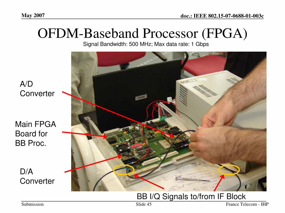
OFDM-Baseband Processor (FPGA)
A/D Converter
D/A Converter
Main FPGA Board for BB Proc.
BB I/Q Signals to/from IF Block
Signal Bandwidth: 500 MHz; Max data rate: 1 Gbps
May 2007
France Telecom - IHPSlide 46
doc.: IEEE 802.15-07-0688-01-003c
Submission
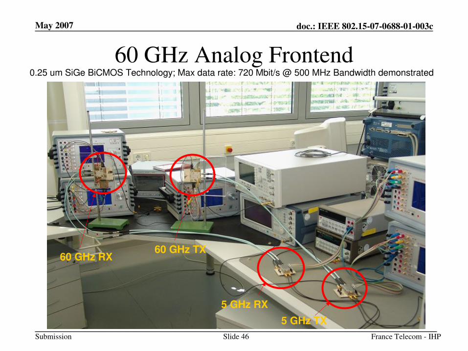
60 GHz Analog Frontend
60 GHz TX60 GHz RX
5 GHz TX
5 GHz RX
0.25 um SiGe BiCMOS Technology; Max data rate: 720 Mbit/s @ 500 MHz Bandwidth demonstrated
May 2007
France Telecom - IHPSlide 47
doc.: IEEE 802.15-07-0688-01-003c
Submission
Open issues
• Addition of a Low Data Rate (LDR) mode for signalling and LDR applications
– Specific 60 GHz channel
– Other technology (UWB, 5 GHz, …)
• Compatibility with other techniques for 60 GHz transmission isdesirable
– SC with FDE, SC, …
• Use of multiple antennas could increase efficiency
– Beamforming
– MIMO STBC
– …
May 2007
France Telecom - IHPSlide 48
doc.: IEEE 802.15-07-0688-01-003c
Submission
Conclusion
• This proposal presents an OFDM based PHY allowing 60 GHz transmission at data rates from 335 Mbps to 3 Gbps
• OFDM presents technical advantages meeting TG3c requirements :
– Inherently robust against any type of fading channel
– Providing high spectrum efficiency and allowing to reach high data rates
• OFDM is a future proof technology
– Mature, widely used technology (WiFi, WiMax, DAB, DVB, ECMA UWB)
– Large scope of possible applications: from point-to-point data transfer to cell mode coverage
– Compatible with advanced techniques: beamforming, MIMO STBC, …
• We are in discussions to converge with Wireless HD, and open to discussions with any companies interested in OFDM or compatible technologies
May 2007
France Telecom - IHPSlide 49
doc.: IEEE 802.15-07-0688-01-003c
Submission
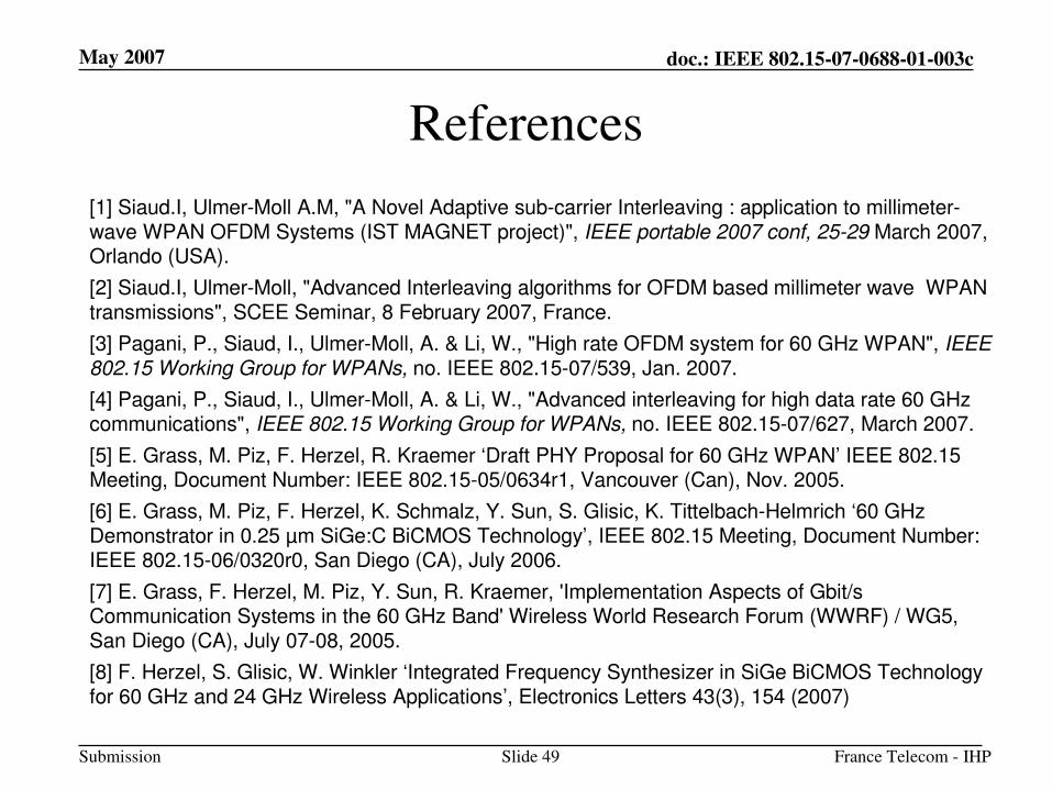
References
[1] Siaud.I, Ulmer-Moll A.M, "A Novel Adaptive sub-carrier Interleaving : application to millimeter-wave WPAN OFDM Systems (IST MAGNET project)", IEEE portable 2007 conf, 25-29 March 2007, Orlando (USA).
[2] Siaud.I, Ulmer-Moll, "Advanced Interleaving algorithms for OFDM based millimeter wave WPAN transmissions", SCEE Seminar, 8 February 2007, France.
[3] Pagani, P., Siaud, I., Ulmer-Moll, A. & Li, W., "High rate OFDM system for 60 GHz WPAN", IEEE 802.15 Working Group for WPANs, no. IEEE 802.15-07/539, Jan. 2007.
[4] Pagani, P., Siaud, I., Ulmer-Moll, A. & Li, W., "Advanced interleaving for high data rate 60 GHz communications", IEEE 802.15 Working Group for WPANs, no. IEEE 802.15-07/627, March 2007.
[5] E. Grass, M. Piz, F. Herzel, R. Kraemer ‘Draft PHY Proposal for 60 GHz WPAN’ IEEE 802.15 Meeting, Document Number: IEEE 802.15-05/0634r1, Vancouver (Can), Nov. 2005.
[6] E. Grass, M. Piz, F. Herzel, K. Schmalz, Y. Sun, S. Glisic, K. Tittelbach-Helmrich ‘60 GHz Demonstrator in 0.25 µm SiGe:C BiCMOS Technology’, IEEE 802.15 Meeting, Document Number: IEEE 802.15-06/0320r0, San Diego (CA), July 2006.
[7] E. Grass, F. Herzel, M. Piz, Y. Sun, R. Kraemer, 'Implementation Aspects of Gbit/sCommunication Systems in the 60 GHz Band' Wireless World Research Forum (WWRF) / WG5, San Diego (CA), July 07-08, 2005.
[8] F. Herzel, S. Glisic, W. Winkler ‘Integrated Frequency Synthesizer in SiGe BiCMOS Technologyfor 60 GHz and 24 GHz Wireless Applications’, Electronics Letters 43(3), 154 (2007)
May 2007
France Telecom - IHPSlide 50
doc.: IEEE 802.15-07-0688-01-003c
Submission
Thank you !
Questions ?
May 2007
France Telecom - IHPSlide 51
doc.: IEEE 802.15-07-0688-01-003c
Submission
Backup slides
May 2007
France Telecom - IHPSlide 52
doc.: IEEE 802.15-07-0688-01-003c
Submission
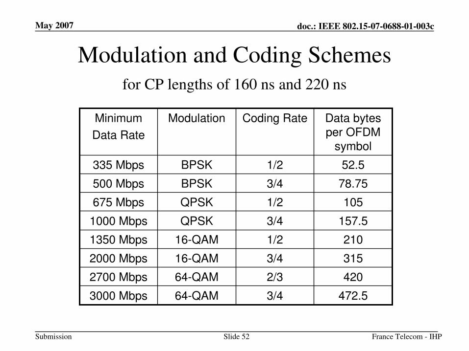
Modulation and Coding Schemes
472.53/464-QAM3000 Mbps
4202/364-QAM2700 Mbps
3153/416-QAM2000 Mbps
2101/216-QAM1350 Mbps
157.53/4QPSK1000 Mbps
1051/2QPSK675 Mbps
78.753/4BPSK500 Mbps
52.51/2BPSK335 Mbps
Data bytes per OFDM
symbol
Coding RateModulationMinimum
Data Rate
for CP lengths of 160 ns and 220 ns