Embed Size (px)
Citation preview
doc.: IEEE 802.15-07-0761-05-003c
Submission Slide 1
July, 2007
Hiroshi Harada, NICT
Project: IEEE P802.15 Working Group for Wireless Personal Area Networks (WPANs)
Submission Title: [Unified and flexible millimeter wave WPAN systems supported by common mode]
Date Submitted: [July 9, 2007]
Source: [Hiroshi Harada (representative contributor), other contributors are listed in “Contributors” slides]
Company [National Institute of Information and Communications Technology (NICT), other contributors
are listed in “Contributors” slides ]
Address1[3-4 Hikari-no-oka, Yokosuka-shi, Kanagawa 239-0847, Japan]
Voice:[+81-46-847-5074]
FAX: [+81-46-847-5440]
E-Mail:[[email protected] (other contributors are listed in “Contributors” slides)]
Re: [In response to TG3c Call for Proposals (IEEE P802.15-07-0586-02-003c)]
Abstract: [Proposal of unified and flexible millimeter wave WPAN systems supported by common mode]
Purpose: [To be considered in TG3C baseline document.]
Notice: This document has been prepared to assist the IEEE P802.15. It is offered as a basis for
discussion and is not binding on the contributing individual(s) or organization(s). The material in this
document is subject to change in form and content after further study. The contributor(s) reserve(s) the
right to add, amend or withdraw material contained herein.
Release: The contributors acknowledge and accept that this contribution becomes the property of IEEE
and may be made publicly available by P802.15.
doc.: IEEE 802.15-07-0761-05-003c
Submission Slide 2
July, 2007
Hiroshi Harada, NICT
Unified and flexible millimeter wave
WPAN systems supported by
common mode
July 9, 2007
doc.: IEEE 802.15-07-0761-05-003c
Submission Slide 3
July, 2007
Hiroshi Harada, NICT
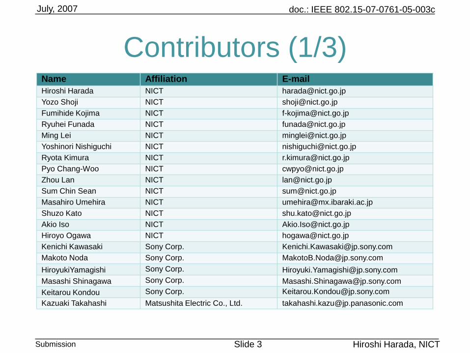
Contributors (1/3)Name Affiliation E-mail
Hiroshi Harada NICT [email protected]
Yozo Shoji NICT [email protected]
Fumihide Kojima NICT [email protected]
Ryuhei Funada NICT [email protected]
Ming Lei NICT [email protected]
Yoshinori Nishiguchi NICT [email protected]
Ryota Kimura NICT [email protected]
Pyo Chang-Woo NICT [email protected]
Zhou Lan NICT [email protected]
Sum Chin Sean NICT [email protected]
Masahiro Umehira NICT [email protected]
Shuzo Kato NICT [email protected]
Akio Iso NICT [email protected]
Hiroyo Ogawa NICT [email protected]
Kenichi Kawasaki Sony Corp. [email protected]
Makoto Noda Sony Corp. [email protected]
HiroyukiYamagishi Sony Corp. [email protected]
Masashi Shinagawa Sony Corp. [email protected]
Keitarou Kondou Sony Corp. [email protected]
Kazuaki Takahashi Matsushita Electric Co., Ltd. [email protected]
doc.: IEEE 802.15-07-0761-05-003c
Submission Slide 4
July, 2007
Hiroshi Harada, NICT
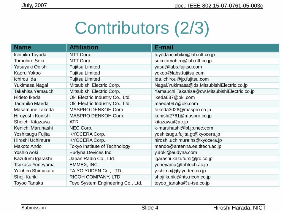
Contributors (2/3)Name Affiliation E-mailIchihiko Toyoda NTT Corp. [email protected]
Tomohiro Seki NTT Corp. [email protected]
Yasuyuki Ooishi Fujitsu Limited [email protected]
Kaoru Yokoo Fujitsu Limited [email protected]
Ichirou Ida Fujitsu Limited [email protected]
Yukimasa Nagai Mitsubishi Electric Corp. [email protected]
Takahisa Yamauchi Mitsubishi Electric Corp. [email protected]
Hideto Ikeda Oki Electric Industry Co., Ltd. [email protected]
Tadahiko Maeda Oki Electric Industry Co., Ltd. [email protected]
Masamune Takeda MASPRO DENKOH Corp. [email protected]
Hiroyoshi Konishi MASPRO DENKOH Corp. [email protected]
Shoichi Kitazawa ATR [email protected]
Kenichi Maruhashi NEC Corp. [email protected]
Yoshitsugu Fujita KYOCERA Corp. [email protected]
Hiroshi Uchimura KYOCERA Corp. [email protected]
Makoto Ando Tokyo Institute of Technology [email protected]
Yoshio Aoki Eudyna Devices Inc [email protected]
Kazufumi Igarashi Japan Radio Co., Ltd. [email protected]
Tsukasa Yoneyama EMMEX, INC. [email protected]
Yukihiro Shimakata TAIYO YUDEN Co., LTD. [email protected]
Shoji Kuriki RICOH COMPANY, LTD. [email protected]
Toyoo Tanaka Toyo System Engineering Co., Ltd. [email protected]
doc.: IEEE 802.15-07-0761-05-003c
Submission Slide 5
July, 2007
Hiroshi Harada, NICT
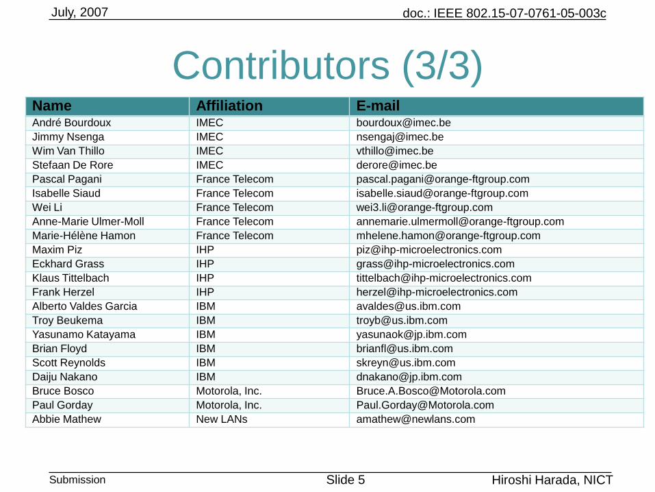
Contributors (3/3)Name Affiliation E-mailAndré Bourdoux IMEC [email protected]
Jimmy Nsenga IMEC [email protected]
Wim Van Thillo IMEC [email protected]
Stefaan De Rore IMEC [email protected]
Pascal Pagani France Telecom [email protected]
Isabelle Siaud France Telecom [email protected]
Wei Li France Telecom [email protected]
Anne-Marie Ulmer-Moll France Telecom [email protected]
Marie-Hélène Hamon France Telecom [email protected]
Maxim Piz IHP [email protected]
Eckhard Grass IHP [email protected]
Klaus Tittelbach IHP [email protected]
Frank Herzel IHP [email protected]
Alberto Valdes Garcia IBM [email protected]
Troy Beukema IBM [email protected]
Yasunamo Katayama IBM [email protected]
Brian Floyd IBM [email protected]
Scott Reynolds IBM [email protected]
Daiju Nakano IBM [email protected]
Bruce Bosco Motorola, Inc. [email protected]
Paul Gorday Motorola, Inc. [email protected]
Abbie Mathew New LANs [email protected]
doc.: IEEE 802.15-07-0761-05-003c
Submission Slide 6
July, 2007
Hiroshi Harada, NICT
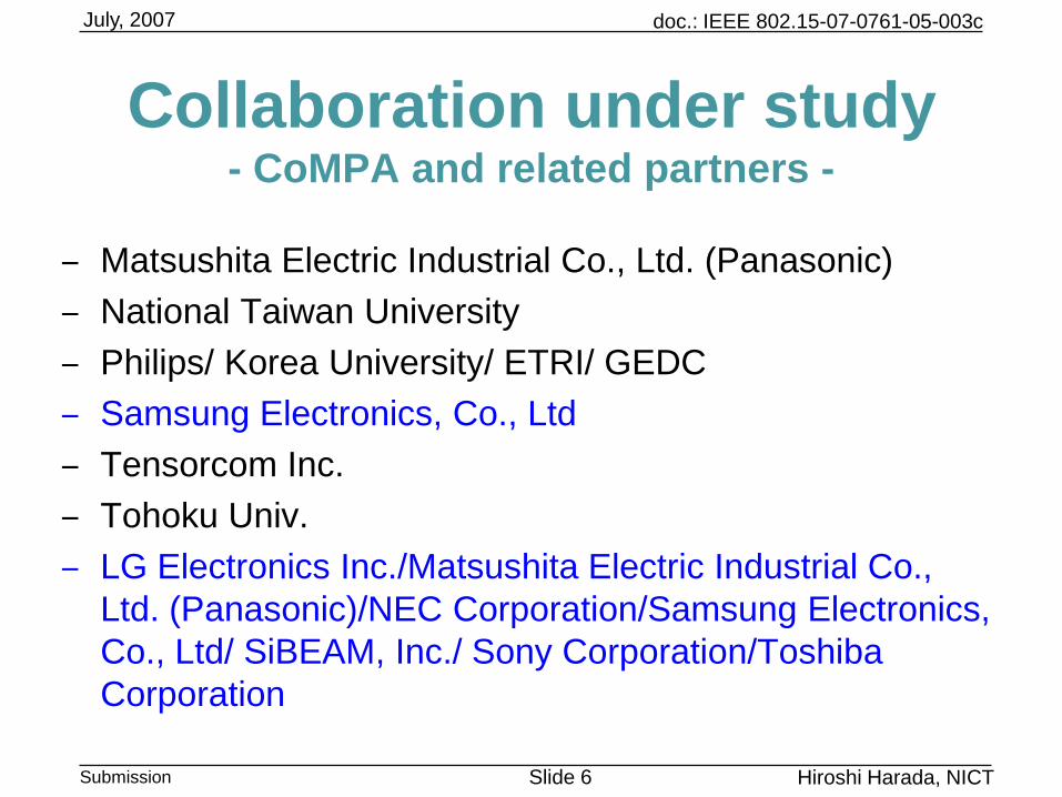
Collaboration under study- CoMPA and related partners -
‒ Matsushita Electric Industrial Co., Ltd. (Panasonic)
‒ National Taiwan University
‒ Philips/ Korea University/ ETRI/ GEDC
‒ Samsung Electronics, Co., Ltd
‒ Tensorcom Inc.
‒ Tohoku Univ.
‒ LG Electronics Inc./Matsushita Electric Industrial Co.,
Ltd. (Panasonic)/NEC Corporation/Samsung Electronics,
Co., Ltd/ SiBEAM, Inc./ Sony Corporation/Toshiba
Corporation
doc.: IEEE 802.15-07-0761-05-003c
Submission Slide 7
July, 2007
Hiroshi Harada, NICT
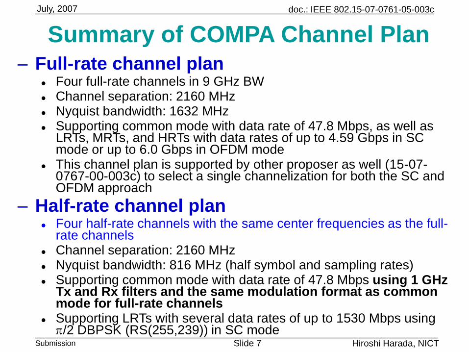
Summary of COMPA Channel Plan – Full-rate channel plan
Four full-rate channels in 9 GHz BW Channel separation: 2160 MHz Nyquist bandwidth: 1632 MHz Supporting common mode with data rate of 47.8 Mbps, as well as
LRTs, MRTs, and HRTs with data rates of up to 4.59 Gbps in SC mode or up to 6.0 Gbps in OFDM mode
This channel plan is supported by other proposer as well (15-07-0767-00-003c) to select a single channelization for both the SC and OFDM approach
– Half-rate channel plan Four half-rate channels with the same center frequencies as the full-
rate channels Channel separation: 2160 MHz Nyquist bandwidth: 816 MHz (half symbol and sampling rates) Supporting common mode with data rate of 47.8 Mbps using 1 GHz
Tx and Rx filters and the same modulation format as common mode for full-rate channels
Supporting LRTs with several data rates of up to 1530 Mbps using p/2 DBPSK (RS(255,239)) in SC mode
doc.: IEEE 802.15-07-0761-05-003c
Submission Slide 8
July, 2007
Hiroshi Harada, NICT
CoMPA Full-rate (2GHz) Channel PlanChannel
Number
Low Freq.
(GHz)
Center Freq.
(GHz)
High Freq.
(GHz)
Nyquist BW
(MHz)
Roll-Off
Factor
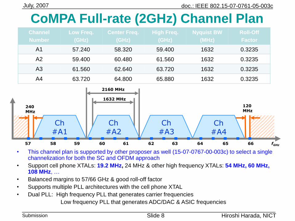
A1 57.240 58.320 59.400 1632 0.3235
A2 59.400 60.480 61.560 1632 0.3235
A3 61.560 62.640 63.720 1632 0.3235
A4 63.720 64.800 65.880 1632 0.3235
• This channel plan is supported by other proposer as well (15-07-0767-00-003c) to select a single channelization for both the SC and OFDM approach
• Support cell phone XTALs: 19.2 MHz, 24 MHz & other high frequency XTALs: 54 MHz, 60 MHz, 108 MHz, …
• Balanced margins to 57/66 GHz & good roll-off factor
• Supports multiple PLL architectures with the cell phone XTAL
• Dual PLL: High frequency PLL that generates carrier frequencies
Low frequency PLL that generates ADC/DAC & ASIC frequencies
Ch#A1
Ch#A2
Ch#A4
240 MHz
120 MHz
1632 MHz
2160 MHz
Ch#A3
57 58 59 60 61 62 63 64 65 66 fGHz
doc.: IEEE 802.15-07-0761-05-003c
Submission Slide 9
July, 2007
Hiroshi Harada, NICT
240 MHz
120 MHz
816 MHz
2160MHz
57 58 59 60 61 62 63 64 65 66 fGHz
Ch#B1
Ch#B2
Ch#B3
Ch#B4
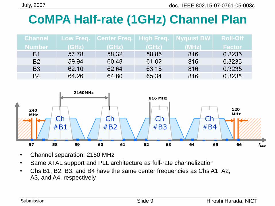
CoMPA Half-rate (1GHz) Channel Plan
• Channel separation: 2160 MHz
• Same XTAL support and PLL architecture as full-rate channelization
• Chs B1, B2, B3, and B4 have the same center frequencies as Chs A1, A2, A3, and A4, respectively
Channel
Number
Low Freq.
(GHz)
Center Freq.
(GHz)
High Freq.
(GHz)
Nyquist BW
(MHz)
Roll-Off
Factor
doc.: IEEE 802.15-07-0761-05-003c
Submission Slide 10
July, 2007
Hiroshi Harada, NICT
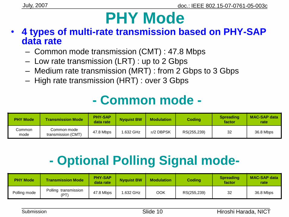
PHY Mode• 4 types of multi-rate transmission based on PHY-SAP
data rate– Common mode transmission (CMT) : 47.8 Mbps
– Low rate transmission (LRT) : up to 2 Gbps
– Medium rate transmission (MRT) : from 2 Gbps to 3 Gbps
– High rate transmission (HRT) : over 3 Gbps
PHY Mode Transmission ModePHY-SAP
data rateNyquist BW Modulation Coding
Spreading
factor
MAC-SAP data
rate
Common
mode
Common mode
transmission (CMT)47.8 Mbps 1.632 GHz p/2 DBPSK RS(255,239) 32 36.8 Mbps
- Optional Polling Signal mode-
- Common mode -
PHY Mode Transmission ModePHY-SAP
data rateNyquist BW Modulation Coding
Spreading
factor
MAC-SAP data
rate
Polling modePolling transmission
(PT)47.8 Mbps 1.632 GHz OOK RS(255,239) 32 36.8 Mbps
doc.: IEEE 802.15-07-0761-05-003c
Submission Slide 11
July, 2007
Hiroshi Harada, NICT
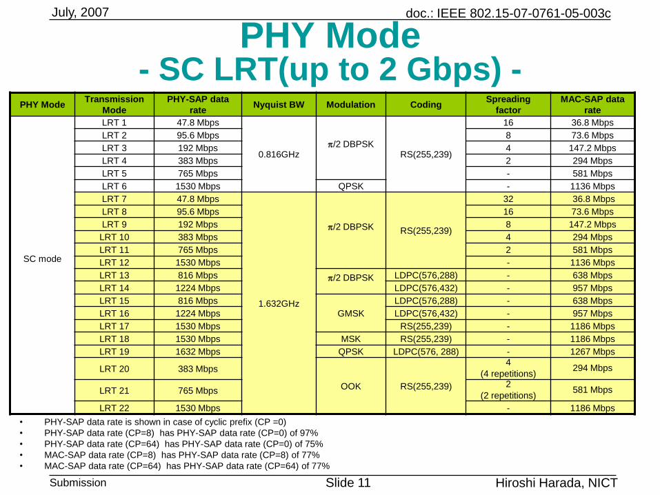
PHY Mode- SC LRT(up to 2 Gbps) -
• PHY-SAP data rate is shown in case of cyclic prefix (CP =0)
• PHY-SAP data rate (CP=8) has PHY-SAP data rate (CP=0) of 97%
• PHY-SAP data rate (CP=64) has PHY-SAP data rate (CP=0) of 75%
• MAC-SAP data rate (CP=8) has PHY-SAP data rate (CP=8) of 77%
• MAC-SAP data rate (CP=64) has PHY-SAP data rate (CP=64) of 77%
PHY ModeTransmission
Mode
PHY-SAP data
rateNyquist BW Modulation Coding
Spreading
factor
MAC-SAP data
rate
SC mode
LRT 1 47.8 Mbps
0.816GHzp/2 DBPSK
RS(255,239)
16 36.8 Mbps
LRT 2 95.6 Mbps 8 73.6 Mbps
LRT 3 192 Mbps 4 147.2 Mbps
LRT 4 383 Mbps 2 294 Mbps
LRT 5 765 Mbps - 581 Mbps
LRT 6 1530 Mbps QPSK - 1136 Mbps
LRT 7 47.8 Mbps
1.632GHz
p/2 DBPSK RS(255,239)
32 36.8 Mbps
LRT 8 95.6 Mbps 16 73.6 Mbps
LRT 9 192 Mbps 8 147.2 Mbps
LRT 10 383 Mbps 4 294 Mbps
LRT 11 765 Mbps 2 581 Mbps
LRT 12 1530 Mbps - 1136 Mbps
LRT 13 816 Mbps p/2 DBPSK LDPC(576,288) - 638 Mbps
LRT 14 1224 Mbps LDPC(576,432) - 957 Mbps
LRT 15 816 Mbps
GMSK
LDPC(576,288) - 638 Mbps
LRT 16 1224 Mbps LDPC(576,432) - 957 Mbps
LRT 17 1530 Mbps RS(255,239) - 1186 Mbps
LRT 18 1530 Mbps MSK RS(255,239) - 1186 Mbps
LRT 19 1632 Mbps QPSK LDPC(576, 288) - 1267 Mbps
LRT 20 383 Mbps
OOK RS(255,239)
4
(4 repetitions)294 Mbps
LRT 21 765 Mbps2
(2 repetitions)581 Mbps
LRT 22 1530 Mbps - 1186 Mbps
doc.: IEEE 802.15-07-0761-05-003c
Submission Slide 12
July, 2007
Hiroshi Harada, NICT
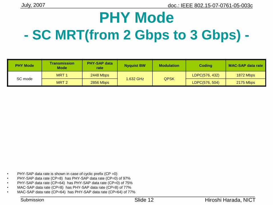
PHY ModeTransmission
Mode
PHY-SAP data
rateNyquist BW Modulation Coding MAC-SAP data rate
SC modeMRT 1 2448 Mbps
1.632 GHz QPSKLDPC(576, 432) 1872 Mbps
MRT 2 2856 Mbps LDPC(576, 504) 2175 Mbps
PHY Mode- SC MRT(from 2 Gbps to 3 Gbps) -
• PHY-SAP data rate is shown in case of cyclic prefix (CP =0)
• PHY-SAP data rate (CP=8) has PHY-SAP data rate (CP=0) of 97%
• PHY-SAP data rate (CP=64) has PHY-SAP data rate (CP=0) of 75%
• MAC-SAP data rate (CP=8) has PHY-SAP data rate (CP=8) of 77%
• MAC-SAP data rate (CP=64) has PHY-SAP data rate (CP=64) of 77%
doc.: IEEE 802.15-07-0761-05-003c
Submission Slide 13
July, 2007
Hiroshi Harada, NICT
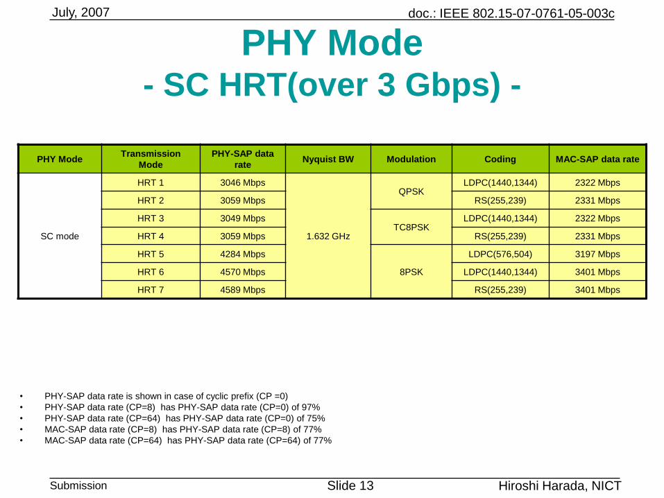
PHY Mode- SC HRT(over 3 Gbps) -
PHY ModeTransmission
Mode
PHY-SAP data
rateNyquist BW Modulation Coding MAC-SAP data rate
SC mode
HRT 1 3046 Mbps
1.632 GHz
QPSKLDPC(1440,1344) 2322 Mbps
HRT 2 3059 Mbps RS(255,239) 2331 Mbps
HRT 3 3049 MbpsTC8PSK
LDPC(1440,1344) 2322 Mbps
HRT 4 3059 Mbps RS(255,239) 2331 Mbps
HRT 5 4284 Mbps
8PSK
LDPC(576,504) 3197 Mbps
HRT 6 4570 Mbps LDPC(1440,1344) 3401 Mbps
HRT 7 4589 Mbps RS(255,239) 3401 Mbps
• PHY-SAP data rate is shown in case of cyclic prefix (CP =0)
• PHY-SAP data rate (CP=8) has PHY-SAP data rate (CP=0) of 97%
• PHY-SAP data rate (CP=64) has PHY-SAP data rate (CP=0) of 75%
• MAC-SAP data rate (CP=8) has PHY-SAP data rate (CP=8) of 77%
• MAC-SAP data rate (CP=64) has PHY-SAP data rate (CP=64) of 77%
doc.: IEEE 802.15-07-0761-05-003c
Submission Slide 14
July, 2007
Hiroshi Harada, NICT
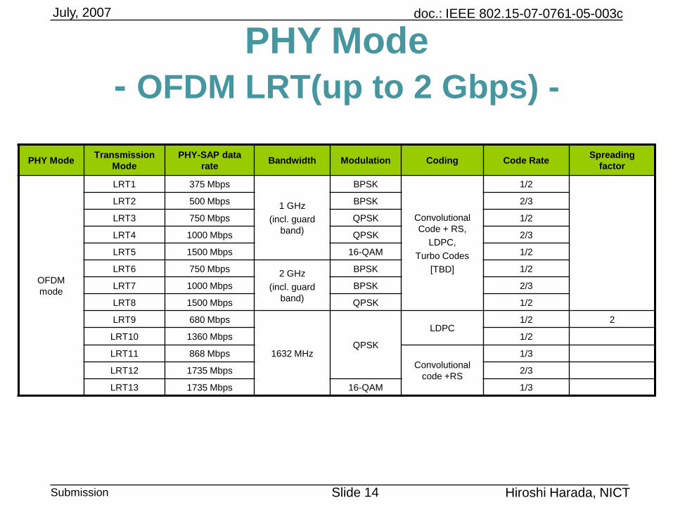
PHY Mode
- OFDM LRT(up to 2 Gbps) -
PHY ModeTransmission
Mode
PHY-SAP data
rateBandwidth Modulation Coding Code Rate
Spreading
factor
OFDM
mode
LRT1 375 Mbps
1 GHz
(incl. guard
band)
BPSK
Convolutional
Code + RS,
LDPC,
Turbo Codes
[TBD]
1/2
LRT2 500 Mbps BPSK 2/3
LRT3 750 Mbps QPSK 1/2
LRT4 1000 Mbps QPSK 2/3
LRT5 1500 Mbps 16-QAM 1/2
LRT6 750 Mbps2 GHz
(incl. guard
band)
BPSK 1/2
LRT7 1000 Mbps BPSK 2/3
LRT8 1500 Mbps QPSK 1/2
LRT9 680 Mbps
1632 MHzQPSK
LDPC1/2 2
LRT10 1360 Mbps 1/2
LRT11 868 Mbps
Convolutional
code +RS
1/3
LRT12 1735 Mbps 2/3
LRT13 1735 Mbps 16-QAM 1/3
doc.: IEEE 802.15-07-0761-05-003c
Submission Slide 15
July, 2007
Hiroshi Harada, NICT
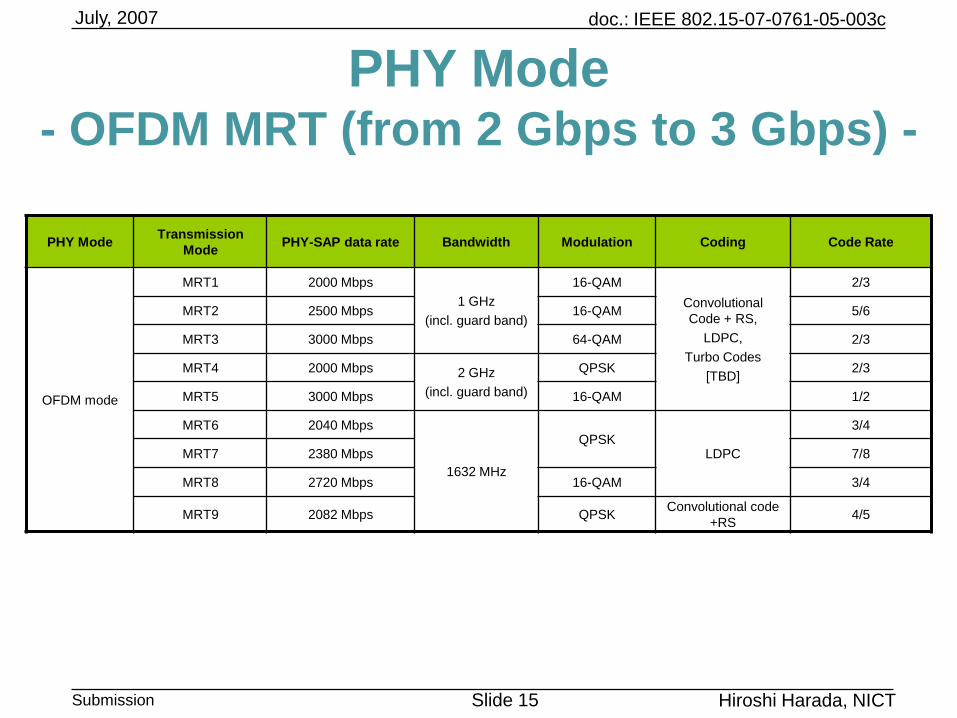
PHY Mode- OFDM MRT (from 2 Gbps to 3 Gbps) -
PHY ModeTransmission
ModePHY-SAP data rate Bandwidth Modulation Coding Code Rate
OFDM mode
MRT1 2000 Mbps
1 GHz
(incl. guard band)
16-QAM
Convolutional
Code + RS,
LDPC,
Turbo Codes
[TBD]
2/3
MRT2 2500 Mbps 16-QAM 5/6
MRT3 3000 Mbps 64-QAM 2/3
MRT4 2000 Mbps 2 GHz
(incl. guard band)
QPSK 2/3
MRT5 3000 Mbps 16-QAM 1/2
MRT6 2040 Mbps
1632 MHz
QPSKLDPC
3/4
MRT7 2380 Mbps 7/8
MRT8 2720 Mbps 16-QAM 3/4
MRT9 2082 Mbps QPSKConvolutional code
+RS4/5
doc.: IEEE 802.15-07-0761-05-003c
Submission Slide 16
July, 2007
Hiroshi Harada, NICT
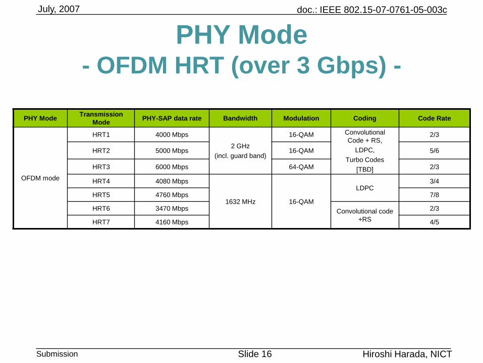
PHY Mode- OFDM HRT (over 3 Gbps) -
PHY ModeTransmission
ModePHY-SAP data rate Bandwidth Modulation Coding Code Rate
OFDM mode
HRT1 4000 Mbps
2 GHz
(incl. guard band)
16-QAM Convolutional
Code + RS,
LDPC,
Turbo Codes
[TBD]
2/3
HRT2 5000 Mbps 16-QAM 5/6
HRT3 6000 Mbps 64-QAM 2/3
HRT4 4080 Mbps
1632 MHz 16-QAM
LDPC3/4
HRT5 4760 Mbps 7/8
HRT6 3470 Mbps Convolutional code
+RS
2/3
HRT7 4160 Mbps 4/5
doc.: IEEE 802.15-07-0761-05-003c
Submission Slide 17
July, 2007
Hiroshi Harada, NICT
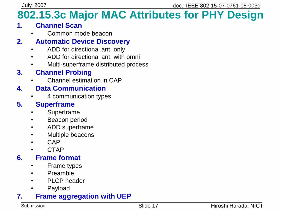
802.15.3c Major MAC Attributes for PHY Design1. Channel Scan
• Common mode beacon
2. Automatic Device Discovery• ADD for directional ant. only
• ADD for directional ant. with omni
• Multi-superframe distributed process
3. Channel Probing• Channel estimation in CAP
4. Data Communication• 4 communication types
5. Superframe• Superframe
• Beacon period
• ADD superframe
• Multiple beacons
• CAP
• CTAP
6. Frame format• Frame types
• Preamble
• PLCP header
• Payload
7. Frame aggregation with UEP
doc.: IEEE 802.15-07-0761-05-003c
Submission Slide 18
July, 2007
Hiroshi Harada, NICT
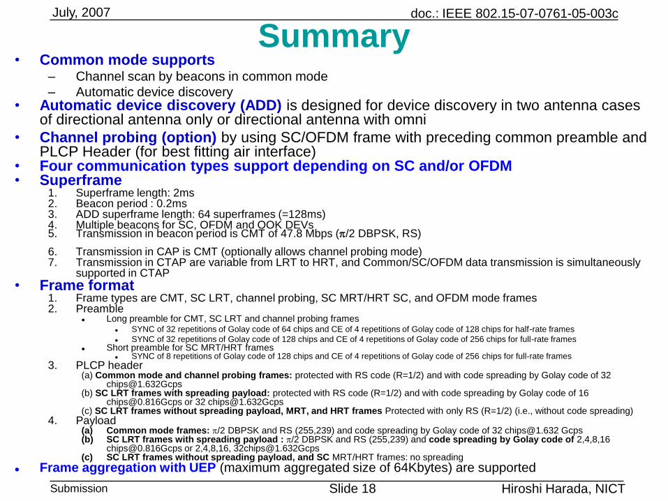
Summary• Common mode supports
– Channel scan by beacons in common mode
– Automatic device discovery• Automatic device discovery (ADD) is designed for device discovery in two antenna cases
of directional antenna only or directional antenna with omni
• Channel probing (option) by using SC/OFDM frame with preceding common preamble and PLCP Header (for best fitting air interface)
• Four communication types support depending on SC and/or OFDM• Superframe
1. Superframe length: 2ms2. Beacon period : 0.2ms3. ADD superframe length: 64 superframes (=128ms)4. Multiple beacons for SC, OFDM and OOK DEVs5. Transmission in beacon period is CMT of 47.8 Mbps (p/2 DBPSK, RS)
6. Transmission in CAP is CMT (optionally allows channel probing mode)7. Transmission in CTAP are variable from LRT to HRT, and Common/SC/OFDM data transmission is simultaneously
supported in CTAP
• Frame format1. Frame types are CMT, SC LRT, channel probing, SC MRT/HRT SC, and OFDM mode frames2. Preamble
Long preamble for CMT, SC LRT and channel probing frames SYNC of 32 repetitions of Golay code of 64 chips and CE of 4 repetitions of Golay code of 128 chips for half-rate frames
SYNC of 32 repetitions of Golay code of 128 chips and CE of 4 repetitions of Golay code of 256 chips for full-rate frames Short preamble for SC MRT/HRT frames
SYNC of 8 repetitions of Golay code of 128 chips and CE of 4 repetitions of Golay code of 256 chips for full-rate frames
3. PLCP header(a) Common mode and channel probing frames: protected with RS code (R=1/2) and with code spreading by Golay code of 32
[email protected](b) SC LRT frames with spreading payload: protected with RS code (R=1/2) and with code spreading by Golay code of 16
[email protected] or 32 [email protected](c) SC LRT frames without spreading payload, MRT, and HRT frames Protected with only RS (R=1/2) (i.e., without code spreading)
4. Payload(a) Common mode frames: p/2 DBPSK and RS (255,239) and code spreading by Golay code of 32 [email protected] Gcps(b) SC LRT frames with spreading payload : p/2 DBPSK and RS (255,239) and code spreading by Golay code of 2,4,8,16
[email protected] or 2,4,8,16, [email protected](c) SC LRT frames without spreading payload, and SC MRT/HRT frames: no spreading
Frame aggregation with UEP (maximum aggregated size of 64Kbytes) are supported
doc.: IEEE 802.15-07-0761-05-003c
Submission Slide 19
July, 2007
Hiroshi Harada, NICT
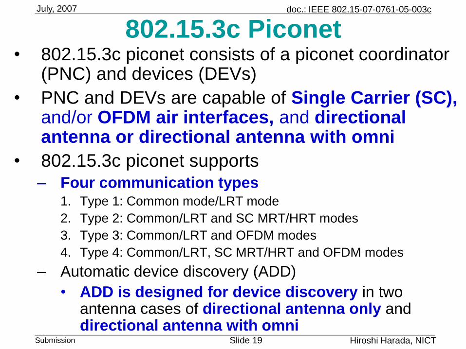
802.15.3c Piconet• 802.15.3c piconet consists of a piconet coordinator
(PNC) and devices (DEVs)
• PNC and DEVs are capable of Single Carrier (SC), and/or OFDM air interfaces, and directional antenna or directional antenna with omni
• 802.15.3c piconet supports – Four communication types
1. Type 1: Common mode/LRT mode
2. Type 2: Common/LRT and SC MRT/HRT modes
3. Type 3: Common/LRT and OFDM modes
4. Type 4: Common/LRT, SC MRT/HRT and OFDM modes
– Automatic device discovery (ADD)
• ADD is designed for device discovery in two antenna cases of directional antenna only and directional antenna with omni
doc.: IEEE 802.15-07-0761-05-003c
Submission Slide 20
July, 2007
Hiroshi Harada, NICT
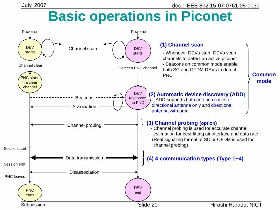
Basic operations in PiconetPower on Power on
DEV
starts
DEV
starts
PNC starts
in a clear
channel
PNC
ends
Channel clear
Channel scan
Session start
Session end
Data transmission
Channel probing
Association
Beacons
(3) Channel probing (option)
Detect a PNC channel
(4) 4 communication types (Type 1~4)
(1) Channel scan
- Whenever DEVs start, DEVs scan
channels to detect an active piconet
- Beacons on common mode enable
both SC and OFDM DEVs to detect
PNC
- Channel probing is used for accurate channel
estimation for best fitting air interface and data rate
(Real signaling format of SC or OFDM is used for
channel probing)
Disassociation
DEV
end
PNC leaves
Common
mode
DEV
responses
to PNC
(2) Automatic device discovery (ADD)- ADD supports both antenna cases of
directional antenna only and directional
antenna with omni
doc.: IEEE 802.15-07-0761-05-003c
Submission Slide 21
July, 2007
Hiroshi Harada, NICT
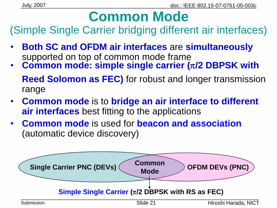
Common Mode(Simple Single Carrier bridging different air interfaces)
• Both SC and OFDM air interfaces are simultaneouslysupported on top of common mode frame
• Common mode: simple single carrier (p/2 DBPSK with
Reed Solomon as FEC) for robust and longer transmission range
• Common mode is to bridge an air interface to different air interfaces best fitting to the applications
• Common mode is used for beacon and association(automatic device discovery)
Common
ModeSingle Carrier PNC (DEVs) OFDM DEVs (PNC)
Simple Single Carrier (p/2 DBPSK with RS as FEC)
doc.: IEEE 802.15-07-0761-05-003c
Submission Slide 22
July, 2007
Hiroshi Harada, NICT
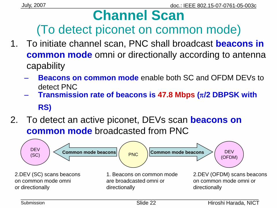
Channel Scan(To detect piconet on common mode)
1. To initiate channel scan, PNC shall broadcast beacons in
common mode omni or directionally according to antenna
capability
– Beacons on common mode enable both SC and OFDM DEVs to
detect PNC– Transmission rate of beacons is 47.8 Mbps (p/2 DBPSK with
RS)
2. To detect an active piconet, DEVs scan beacons on
common mode broadcasted from PNC
PNCDEV
(OFDM)Common mode beacons
1. Beacons on common mode
are broadcasted omni or
directionally
2.DEV (OFDM) scans beacons
on common mode omni or
directionally
Common mode beaconsDEV
(SC)
2.DEV (SC) scans beacons
on common mode omni
or directionally
doc.: IEEE 802.15-07-0761-05-003c
Submission Slide 23
July, 2007
Hiroshi Harada, NICT
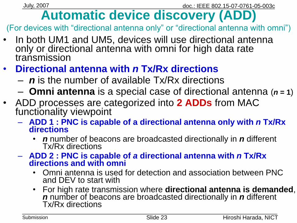
Automatic device discovery (ADD)(For devices with “directional antenna only” or “directional antenna with omni”)
• In both UM1 and UM5, devices will use directional antenna only or directional antenna with omni for high data rate transmission
• Directional antenna with n Tx/Rx directions– n is the number of available Tx/Rx directions– Omni antenna is a special case of directional antenna (n = 1)
• ADD processes are categorized into 2 ADDs from MAC functionality viewpoint– ADD 1 : PNC is capable of a directional antenna only with n Tx/Rx
directions• n number of beacons are broadcasted directionally in n different
Tx/Rx directions– ADD 2 : PNC is capable of a directional antenna with n Tx/Rx
directions and with omni • Omni antenna is used for detection and association between PNC
and DEV to start with• For high rate transmission where directional antenna is demanded,
n number of beacons are broadcasted directionally in n different Tx/Rx directions
doc.: IEEE 802.15-07-0761-05-003c
Submission Slide 24
July, 2007
Hiroshi Harada, NICT
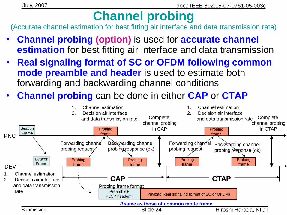
Channel probing(Accurate channel estimation for best fitting air interface and data transmission rate)
• Channel probing (option) is used for accurate channel estimation for best fitting air interface and data transmission
• Real signaling format of SC or OFDM following common mode preamble and header is used to estimate both forwarding and backwarding channel conditions
• Channel probing can be done in either CAP or CTAP
PNC
DEV
Beacon
Frame
1. Channel estimation
2. Decision air interface
and data transmission
rate
Complete
channel probing
in CTAP
CAP
Probing
frame
Probing
frame
Probing
frame
Forwarding channel
probing request
Forwarding channel
probing request
Backwarding channel
probing response (ok)Backwarding channel
probing response (ok)
CTAP
Beacon
Frame
Complete
channel probing
in CAP
1. Channel estimation
2. Decision air interface
and data transmission rate
1. Channel estimation
2. Decision air interface
and data transmission rate
Probing
frame
Probing
frame
Probing
frame
Payload(Real signaling format of SC or OFDM)Preamble+
PLCP header(*)
Probing frame format
(*) same as those of common mode frame
doc.: IEEE 802.15-07-0761-05-003c
Submission Slide 25
July, 2007
Hiroshi Harada, NICT
25252525
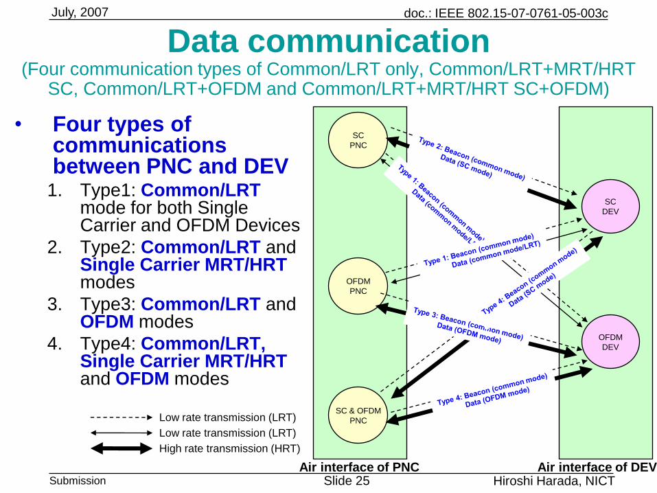
Data communication(Four communication types of Common/LRT only, Common/LRT+MRT/HRT
SC, Common/LRT+OFDM and Common/LRT+MRT/HRT SC+OFDM)
• Four types of communications between PNC and DEV
1. Type1: Common/LRT mode for both Single Carrier and OFDM Devices
2. Type2: Common/LRT and Single Carrier MRT/HRT modes
3. Type3: Common/LRT and OFDM modes
4. Type4: Common/LRT, Single Carrier MRT/HRT and OFDM modes
SC
DEV
OFDM
DEV
SC
PNC
OFDM
PNC
SC & OFDM
PNC
Air interface of PNC Air interface of DEV
Low rate transmission (LRT)
Low rate transmission (LRT)
High rate transmission (HRT)
doc.: IEEE 802.15-07-0761-05-003c
Submission Slide 26
July, 2007
Hiroshi Harada, NICT
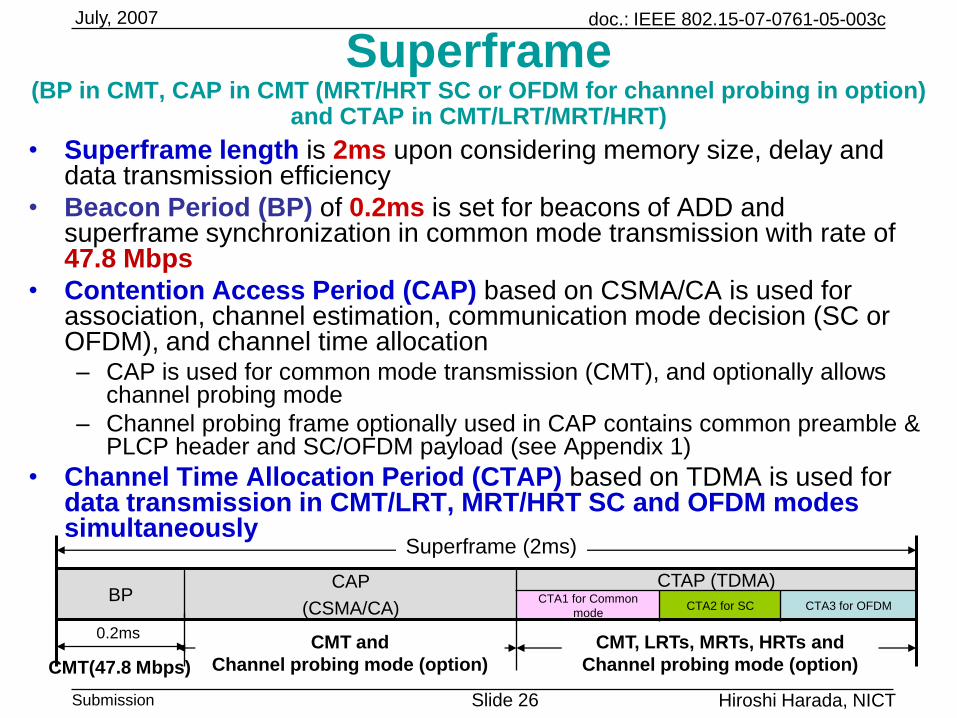
Superframe(BP in CMT, CAP in CMT (MRT/HRT SC or OFDM for channel probing in option)
and CTAP in CMT/LRT/MRT/HRT)
• Superframe length is 2ms upon considering memory size, delay and data transmission efficiency
• Beacon Period (BP) of 0.2ms is set for beacons of ADD and superframe synchronization in common mode transmission with rate of 47.8 Mbps
• Contention Access Period (CAP) based on CSMA/CA is used for association, channel estimation, communication mode decision (SC or OFDM), and channel time allocation– CAP is used for common mode transmission (CMT), and optionally allows
channel probing mode
– Channel probing frame optionally used in CAP contains common preamble & PLCP header and SC/OFDM payload (see Appendix 1)
• Channel Time Allocation Period (CTAP) based on TDMA is used for data transmission in CMT/LRT, MRT/HRT SC and OFDM modes simultaneously
0.2ms
BPCAP
(CSMA/CA)
CTAP (TDMA)CTA1 for Common
modeCTA2 for SC CTA3 for OFDM
Superframe (2ms)
CMT(47.8 Mbps)
CMT and
Channel probing mode (option)
CMT, LRTs, MRTs, HRTs and
Channel probing mode (option)
doc.: IEEE 802.15-07-0761-05-003c
Submission Slide 27
July, 2007
Hiroshi Harada, NICT
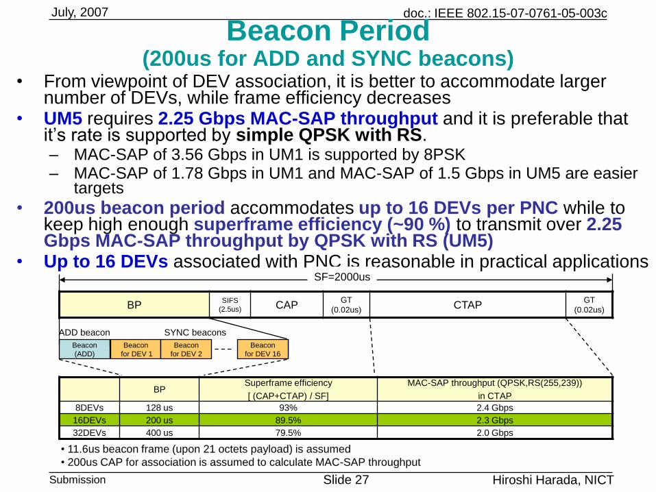
Beacon Period(200us for ADD and SYNC beacons)
• From viewpoint of DEV association, it is better to accommodate larger number of DEVs, while frame efficiency decreases
• UM5 requires 2.25 Gbps MAC-SAP throughput and it is preferable that it‟s rate is supported by simple QPSK with RS.– MAC-SAP of 3.56 Gbps in UM1 is supported by 8PSK– MAC-SAP of 1.78 Gbps in UM1 and MAC-SAP of 1.5 Gbps in UM5 are easier
targets
• 200us beacon period accommodates up to 16 DEVs per PNC while to keep high enough superframe efficiency (~90 %) to transmit over 2.25 Gbps MAC-SAP throughput by QPSK with RS (UM5)
• Up to 16 DEVs associated with PNC is reasonable in practical applications
BPSuperframe efficiency
[ (CAP+CTAP) / SF]
MAC-SAP throughput (QPSK,RS(255,239))
in CTAP
8DEVs 128 us 93% 2.4 Gbps
16DEVs 200 us 89.5% 2.3 Gbps
32DEVs 400 us 79.5% 2.0 Gbps
BPSIFS
(2.5us) CAPGT
(0.02us)CTAP
GT
(0.02us)
SF=2000us
Beacon
(ADD)
SYNC beaconsADD beacon
G
TBeacon
for DEV 1
Beacon
for DEV 2
Beacon
for DEV 16
• 11.6us beacon frame (upon 21 octets payload) is assumed
• 200us CAP for association is assumed to calculate MAC-SAP throughput
doc.: IEEE 802.15-07-0761-05-003c
Submission Slide 28
July, 2007
Hiroshi Harada, NICT
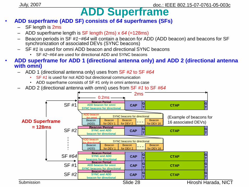
ADD Superframe• ADD superframe (ADD SF) consists of 64 superframes (SFs)
– SF length is 2ms
– ADD superframe length is SF length (2ms) x 64 (=128ms)
– Beacon periods in SF #1~#64 will contain a beacon for ADD (ADD beacon) and beacons for SF synchronization of associated DEVs (SYNC beacons)
– SF #1 is used for omni ADD beacon and directional SYNC beacons• SF #2~#64 are used for directional ADD and SYNC beacons
• ADD superframe for ADD 1 (directional antenna only) and ADD 2 (directional antenna with omni)
– ADD 1 (directional antenna only) uses from SF #2 to SF #64• SF #1 is used for not ADD but directional communication
• ADD superframe consists of SF #1 only in omni antenna case
– ADD 2 (directional antenna with omni) uses from SF #1 to SF #64
SF #1 CAPG
TADD beacon for omni
SYNC beacons for directional
Beacon Period
CAPG
TCTAP
G
T
ADD Superframe
= 128msSF #2 Beacon frame for direction 1
Beacon PeriodCAP
G
TSYNC and ADD
beacon for directionalCAP
G
TCTAP
G
T
SF #64 CAPG
TCTAP
G
T
SF #1 CAPG
TCTAP
G
T
SF #2 Beacon frame for direction 1
Beacon PeriodCAP
G
TSYNC and ADD
beacon for directional
Beacon Period
CAPG
TCTAP
G
T
2ms
(Example of beacons for
16 associated DEVs)Beacon
(ADD)
SYNC beacons for directionalADD beacon
for omniG
T
Beacon
for DEV 1
Beacon
for DEV 2
Beacon
for DEV 16
SYNC and ADD
beacons for directional
Beacon Period
ADD beacon for omni
SYNC beacons for directional
Beacon Period
0.2ms
Beacon
(ADD)
SYNC beacons for directionalADD beacon
for directionalG
T
Beacon
for DEV 1
Beacon
for DEV 2
Beacon
for DEV 16
doc.: IEEE 802.15-07-0761-05-003c
Submission Slide 29
July, 2007
Hiroshi Harada, NICT
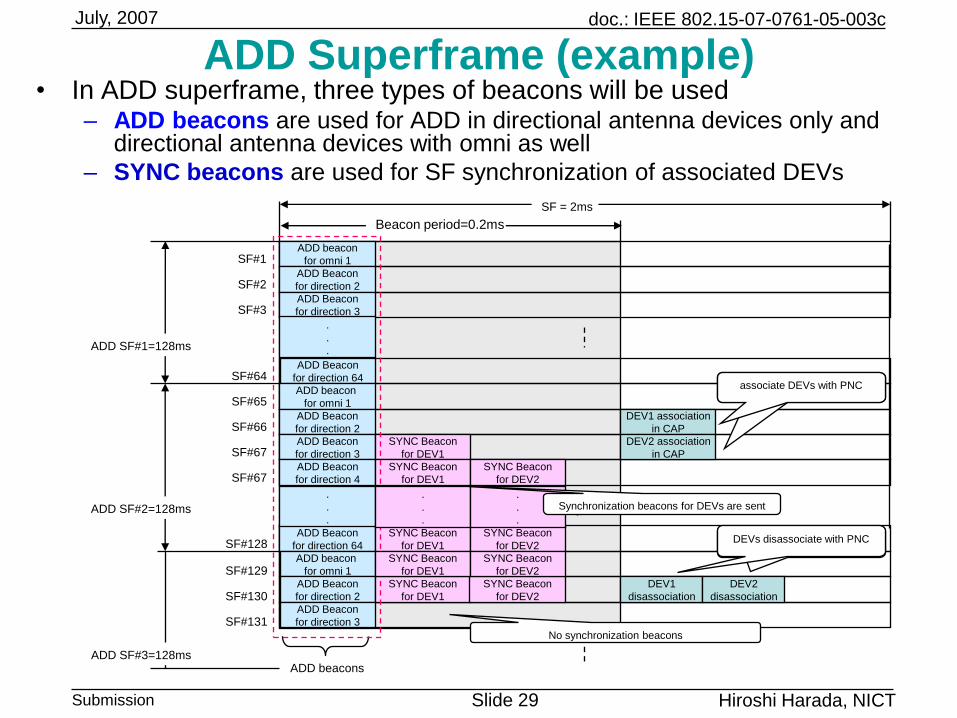
ADD Superframe (example)• In ADD superframe, three types of beacons will be used
– ADD beacons are used for ADD in directional antenna devices only and directional antenna devices with omni as well
– SYNC beacons are used for SF synchronization of associated DEVs
SF#1
SF#2
SF#64
SF#65
SF#66
SF#67
SF = 2ms
ADD SF#1=128ms
SF#3
SF#67
SF#128
ADD SF#2=128ms
SF#129
ADD beacon
for omni 1
ADD Beacon
for direction 2
ADD Beacon
for direction 64
ADD beacon
for omni 1
ADD Beacon
for direction 2
DEV1 association
in CAP
ADD Beacon
for direction 3
ADD Beacon
for direction 3
SYNC Beacon
for DEV1
DEV2 association
in CAP
ADD Beacon
for direction 4
SYNC Beacon
for DEV1
SYNC Beacon
for DEV2
ADD Beacon
for direction 64
SYNC Beacon
for DEV1
SYNC Beacon
for DEV2
ADD beacon
for omni 1
ADD Beacon
for direction 2
SYNC Beacon
for DEV1
SYNC Beacon
for DEV2
DEV1
disassociation
DEV2
disassociation
ADD Beacon
for direction 3
ADD SF#3=128ms
DEVs disassociate with PNC
No synchronization beacons
associate DEVs with PNC
ADD beacons
SF#130
SF#131
Beacon period=0.2ms
DEVs disassociate with PNC
SYNC Beacon
for DEV1
SYNC Beacon
for DEV2
.
.
.
.
.
.
.
.
.
.
.
.
Synchronization beacons for DEVs are sent
doc.: IEEE 802.15-07-0761-05-003c
Submission Slide 30
July, 2007
Hiroshi Harada, NICT
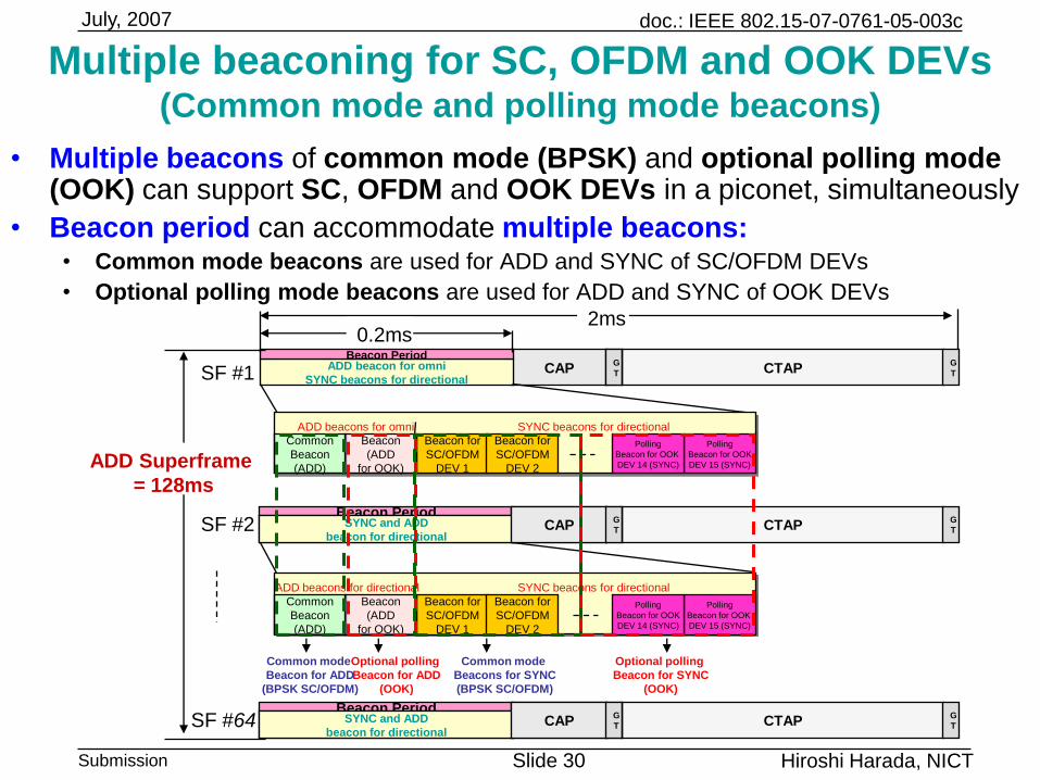
Multiple beaconing for SC, OFDM and OOK DEVs(Common mode and polling mode beacons)
• Multiple beacons of common mode (BPSK) and optional polling mode (OOK) can support SC, OFDM and OOK DEVs in a piconet, simultaneously
• Beacon period can accommodate multiple beacons:• Common mode beacons are used for ADD and SYNC of SC/OFDM DEVs
• Optional polling mode beacons are used for ADD and SYNC of OOK DEVs
CAPG
TADD beacon for omni
SYNC beacons for directional
Beacon PeriodG
T CTAPG
T
Beacon frame for direction 1
Beacon PeriodCAP
G
TSYNC and ADD
beacon for directionalCAP
G
T CTAPG
T
Beacon frame for direction 1
Beacon PeriodCAP
G
TSYNC and ADD
beacon for directionalCAP
G
T CTAPG
T
Common
Beacon
(ADD)
SYNC beacons for directionalADD beacons for omni
Beacon for
SC/OFDM
DEV 1
Polling
Beacon for OOK
DEV 15 (SYNC)
Polling
Beacon for OOK
DEV 14 (SYNC)
Common
Beacon
(ADD)
SYNC beacons for directionalADD beacons for directional
Beacon for
SC/OFDM
DEV 1
Polling
Beacon for OOK
DEV 15 (SYNC)
2ms0.2ms
SF #1
SF #2
SF #64
Polling
Beacon for OOK
DEV 14 (SYNC)
Beacon for
SC/OFDM
DEV 2
Beacon for
SC/OFDM
DEV 2
Beacon
(ADD
for OOK)
Beacon
(ADD
for OOK)
Common mode
Beacon for ADD
(BPSK SC/OFDM)
Optional polling
Beacon for ADD
(OOK)
Common mode
Beacons for SYNC
(BPSK SC/OFDM)
Optional polling
Beacon for SYNC
(OOK)
ADD Superframe
= 128ms
doc.: IEEE 802.15-07-0761-05-003c
Submission Slide 31
July, 2007
Hiroshi Harada, NICT
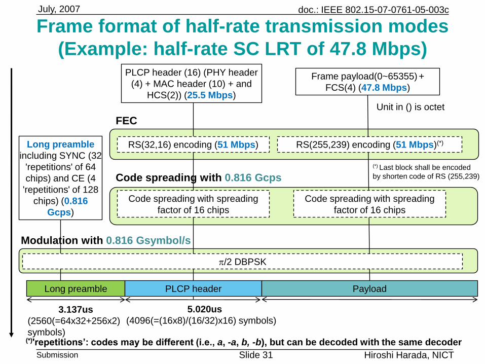
Frame format of half-rate transmission modes
(Example: half-rate SC LRT of 47.8 Mbps)
RS(32,16) encoding (51 Mbps) RS(255,239) encoding (51 Mbps)(*)
PLCP header (16) (PHY header
(4) + MAC header (10) + and
HCS(2)) (25.5 Mbps)
Frame payload(0~65355) +
FCS(4) (47.8 Mbps)
FEC
Modulation with 0.816 Gsymbol/s
Code spreading with 0.816 Gcps
Code spreading with spreading
factor of 16 chips
Code spreading with spreading
factor of 16 chips
Long preamble
including SYNC (32
'repetitions' of 64
chips) and CE (4
'repetitions' of 128
chips) (0.816
Gcps)
Long preamble PLCP header Payload
3.137us
(2560(=64x32+256x2)
symbols)
5.020us
(4096(=(16x8)/(16/32)x16) symbols)
Unit in () is octet
(*) Last block shall be encoded
by shorten code of RS (255,239)
p/2 DBPSK
(*)'repetitions’: codes may be different (i.e., a, -a, b, -b), but can be decoded with the same decoder
doc.: IEEE 802.15-07-0761-05-003c
Submission Slide 32
July, 2007
Hiroshi Harada, NICT
3232
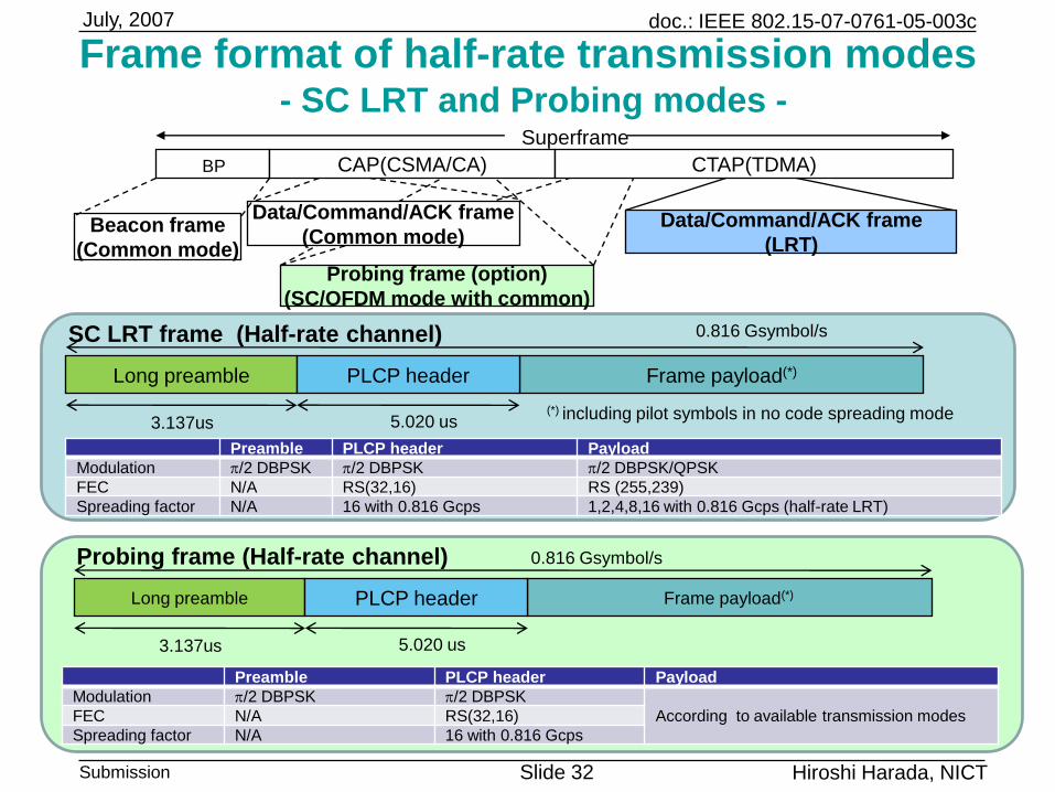
Frame format of half-rate transmission modes- SC LRT and Probing modes -
Probing frame (Half-rate channel)
Long preamble Frame payload(*)PLCP header
SC LRT frame (Half-rate channel)
3.137us
0.816 Gsymbol/s
Preamble PLCP header Payload
Modulation p/2 DBPSK p/2 DBPSK p/2 DBPSK/QPSK
FEC N/A RS(32,16) RS (255,239)
Spreading factor N/A 16 with 0.816 Gcps 1,2,4,8,16 with 0.816 Gcps (half-rate LRT)
Preamble PLCP header Payload
Modulation p/2 DBPSK p/2 DBPSK
According to available transmission modesFEC N/A RS(32,16)
Spreading factor N/A 16 with 0.816 Gcps
CAP(CSMA/CA) CTAP(TDMA)
Data/Command/ACK frame
(Common mode)Data/Command/ACK frame
(LRT)Beacon frame
(Common mode)
BP
Probing frame (option)
(SC/OFDM mode with common)
Superframe
5.020 us
Long preamble Frame payload(*)
3.137us
0.816 Gsymbol/s
5.020 us
PLCP header
(*) including pilot symbols in no code spreading mode
doc.: IEEE 802.15-07-0761-05-003c
Submission Slide 33
July, 2007
Hiroshi Harada, NICT
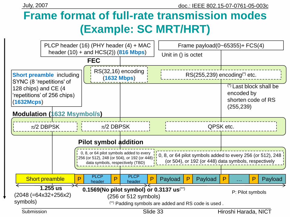
PLCP header (16) (PHY header (4) + MAC
header (10) + and HCS(2)) (816 Mbps)
Frame payload(0~65355)+ FCS(4)
FEC
Modulation (1632 Msymbol/s)
Short preamble including
SYNC (8 „repetitions' of
128 chips) and CE (4
„repetitions‟ of 256 chips)
(1632Mcps)
(*) Last block shall be
encoded by
shorten code of RS
(255,239)
Frame format of full-rate transmission modes
(Example: SC MRT/HRT)
Unit in () is octet
Short preamble Payload
0.1569(No pilot symbol) or 0.3137 us(**)
(256 or 512 symbols)
0, 8, or 64 pilot symbols added to every
256 (or 512), 248 (or 504), or 192 (or 448)
data symbols, respectively (TBD)
0, 8, or 64 pilot symbols added to every 256 (or 512), 248
(or 504), or 192 (or 448) data symbols, respectively
Pilot symbol addition
p/2 DBPSK QPSK etc.p/2 DBPSK
1.255 us
(2048 (=64x32+256x2)
symbols)
P Payload PayloadPPLCP
headerP
PLCP
headerP P P…
(**) Padding symbols are added and RS code is used .
RS(32,16) encoding
(1632 Mbps)RS(255,239) encoding(*) etc.
P: Pilot symbols
doc.: IEEE 802.15-07-0761-05-003c
Submission Slide 34
July, 2007
Hiroshi Harada, NICT
3434
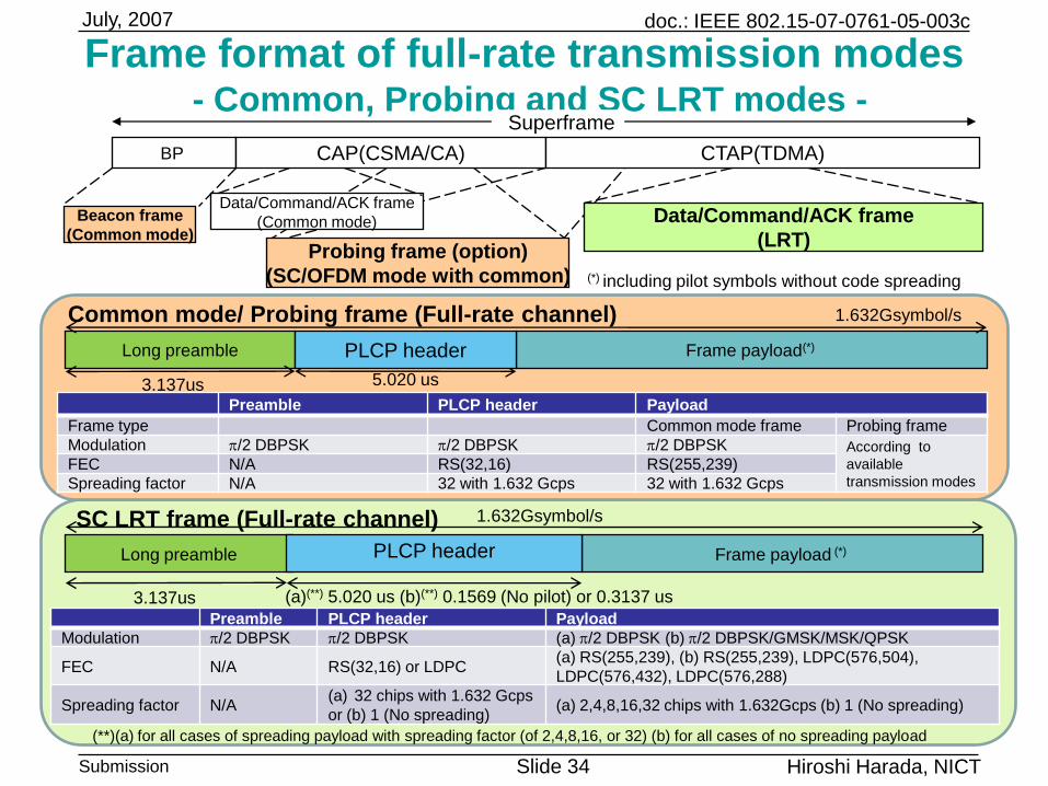
Frame format of full-rate transmission modes- Common, Probing and SC LRT modes -
SC LRT frame (Full-rate channel)
Long preamble
Common mode/ Probing frame (Full-rate channel) 1.632Gsymbol/s
1.632Gsymbol/s
Preamble PLCP header Payload
Modulation p/2 DBPSK p/2 DBPSK (a) p/2 DBPSK (b) p/2 DBPSK/GMSK/MSK/QPSK
FEC N/A RS(32,16) or LDPC(a) RS(255,239), (b) RS(255,239), LDPC(576,504),
LDPC(576,432), LDPC(576,288)
Spreading factor N/A(a) 32 chips with 1.632 Gcps
or (b) 1 (No spreading)(a) 2,4,8,16,32 chips with 1.632Gcps (b) 1 (No spreading)
Frame payload(*)
Long preamble Frame payload (*) PLCP header
5.020 us3.137us
3.137us
Preamble PLCP header Payload
Frame type Common mode frame Probing frame
Modulation p/2 DBPSK p/2 DBPSK p/2 DBPSK According to
available
transmission modesFEC N/A RS(32,16) RS(255,239)
Spreading factor N/A 32 with 1.632 Gcps 32 with 1.632 Gcps
(a)(**) 5.020 us (b)(**) 0.1569 (No pilot) or 0.3137 us
PLCP header
CAP(CSMA/CA) CTAP(TDMA)
Data/Command/ACK frame
(Common mode) Data/Command/ACK frame
(LRT)
Beacon frame
(Common mode)
BP
Probing frame (option)
(SC/OFDM mode with common)
Superframe
(*) including pilot symbols without code spreading
(**)(a) for all cases of spreading payload with spreading factor (of 2,4,8,16, or 32) (b) for all cases of no spreading payload
doc.: IEEE 802.15-07-0761-05-003c
Submission Slide 35
July, 2007
Hiroshi Harada, NICT
3535
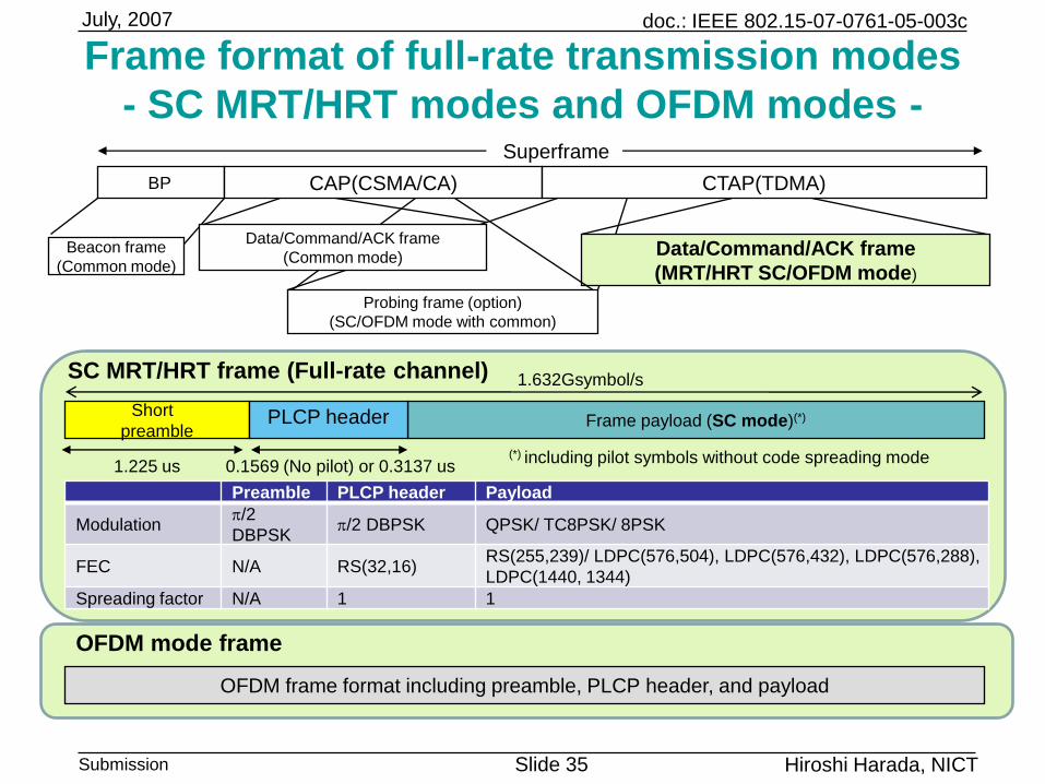
Frame format of full-rate transmission modes
- SC MRT/HRT modes and OFDM modes -
OFDM mode frame
SC MRT/HRT frame (Full-rate channel) 1.632Gsymbol/s
Preamble PLCP header Payload
Modulationp/2
DBPSKp/2 DBPSK QPSK/ TC8PSK/ 8PSK
FEC N/A RS(32,16)RS(255,239)/ LDPC(576,504), LDPC(576,432), LDPC(576,288),
LDPC(1440, 1344)
Spreading factor N/A 1 1
OFDM frame format including preamble, PLCP header, and payload
1.225 us 0.1569 (No pilot) or 0.3137 us
Short
preambleFrame payload (SC mode)(*)PLCP header
CAP(CSMA/CA) CTAP(TDMA)
Data/Command/ACK frame
(MRT/HRT SC/OFDM mode)
BP
Superframe
Probing frame (option)
(SC/OFDM mode with common)
Data/Command/ACK frame
(Common mode)Beacon frame
(Common mode)
(*) including pilot symbols without code spreading mode
doc.: IEEE 802.15-07-0761-05-003c
Submission Slide 36
July, 2007
Hiroshi Harada, NICT
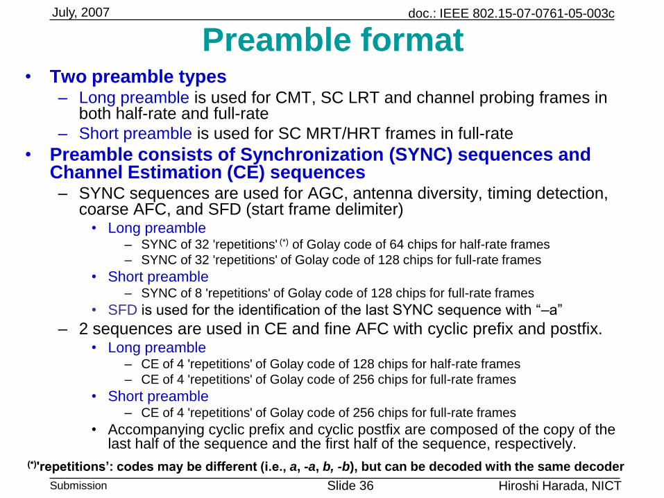
Preamble format• Two preamble types
– Long preamble is used for CMT, SC LRT and channel probing frames in both half-rate and full-rate
– Short preamble is used for SC MRT/HRT frames in full-rate
• Preamble consists of Synchronization (SYNC) sequences and Channel Estimation (CE) sequences– SYNC sequences are used for AGC, antenna diversity, timing detection,
coarse AFC, and SFD (start frame delimiter)• Long preamble
– SYNC of 32 'repetitions' (*) of Golay code of 64 chips for half-rate frames
– SYNC of 32 'repetitions' of Golay code of 128 chips for full-rate frames
• Short preamble– SYNC of 8 'repetitions' of Golay code of 128 chips for full-rate frames
• SFD is used for the identification of the last SYNC sequence with “–a”
– 2 sequences are used in CE and fine AFC with cyclic prefix and postfix. • Long preamble
– CE of 4 'repetitions' of Golay code of 128 chips for half-rate frames
– CE of 4 'repetitions' of Golay code of 256 chips for full-rate frames
• Short preamble– CE of 4 'repetitions' of Golay code of 256 chips for full-rate frames
• Accompanying cyclic prefix and cyclic postfix are composed of the copy of the last half of the sequence and the first half of the sequence, respectively.
(*)'repetitions’: codes may be different (i.e., a, -a, b, -b), but can be decoded with the same decoder
doc.: IEEE 802.15-07-0761-05-003c
Submission Slide 37
July, 2007
Hiroshi Harada, NICT
3737
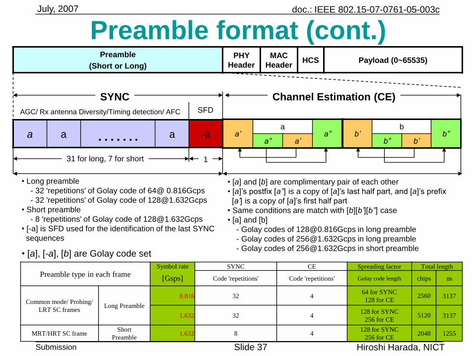
Preamble format (cont.)Preamble
(Short or Long)
PHY
Header
MAC
HeaderHCS Payload (0~65535)
a’a
a’’a” a’
b’b
b’’b” b’
a a ……. a -a
AGC/ Rx antenna Diversity/Timing detection/ AFC
SYNC Channel Estimation (CE)SFD
• Long preamble
- 32 'repetitions' of Golay code of 64@ 0.816Gcps
- 32 'repetitions' of Golay code of [email protected]
• Short preamble
- 8 'repetitions' of Golay code of [email protected]
• [-a] is SFD used for the identification of the last SYNC
sequences
31 for long, 7 for short 1
• [a] and [b] are complimentary pair of each other
• [a]‟s postfix [a’’] is a copy of [a]‟s last half part, and [a]‟s prefix
[a’] is a copy of [a]‟s first half part
• Same conditions are match with [b][b’][b’’] case
• [a] and [b]
- Golay codes of [email protected] in long preamble
- Golay codes of [email protected] in long preamble
- Golay codes of [email protected] in short preamble• [a], [-a], [b] are Golay code set
Preamble type in each frameSymbol rate SYNC CE Spreading factor Total length
[Gsps] Code 'repetitions' Code 'repetitions' Golay code length chips ns
Common mode/ Probing/
LRT SC framesLong Preamble
0.816 32 464 for SYNC
128 for CE2560 3137
1.632 32 4128 for SYNC
256 for CE5120 3137
MRT/HRT SC frameShort
Preamble1.632 8 4
128 for SYNC
256 for CE2048 1255
doc.: IEEE 802.15-07-0761-05-003c
Submission Slide 38
July, 2007
Hiroshi Harada, NICT
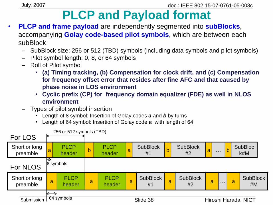
PLCP and Payload format• PLCP and frame payload are independently segmented into subBlocks,
accompanying Golay code-based pilot symbols, which are between each
subBlock– SubBlock size: 256 or 512 (TBD) symbols (including data symbols and pilot symbols)
– Pilot symbol length: 0, 8, or 64 symbols
– Roll of Pilot symbol
• (a) Timing tracking, (b) Compensation for clock drift, and (c) Compensation
for frequency offset error that resides after fine AFC and that caused by
phase noise in LOS environment
• Cyclic prefix (CP) for frequency domain equalizer (FDE) as well in NLOS
environment
– Types of pilot symbol insertion• Length of 8 symbol: Insertion of Golay codes a and b by turns
• Length of 64 symbol: Insertion of Golay code a with length of 64
64 symbols
Short or long
preamblea
PLCP
headerb
PLCP
headera
SubBlock
#1b
SubBlock
#2a … b
SubBloc
k#M
256 or 512 symbols (TBD)
Short or long
preamblea
PLCP
headera
PLCP
headera
SubBlock
#1a
SubBlock
#2a … a
SubBlock
#M
8 symbols
For LOS
For NLOS
doc.: IEEE 802.15-07-0761-05-003c
Submission Slide 39
July, 2007
Hiroshi Harada, NICT
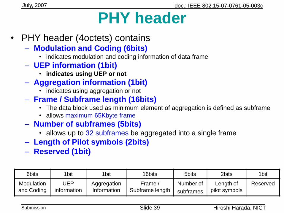
PHY header• PHY header (4octets) contains
– Modulation and Coding (6bits)• indicates modulation and coding information of data frame
– UEP information (1bit)• indicates using UEP or not
– Aggregation information (1bit) • indicates using aggregation or not
– Frame / Subframe length (16bits)• The data block used as minimum element of aggregation is defined as subframe
• allows maximum 65Kbyte frame
– Number of subframes (5bits)• allows up to 32 subframes be aggregated into a single frame
– Length of Pilot symbols (2bits)
– Reserved (1bit)
6bits 1bit 1bit 16bits 5bits 2bits 1bit
Modulation
and Coding
UEP
information
Aggregation
Information
Frame /
Subframe length
Number of
subframes
Length of
pilot symbols
Reserved
doc.: IEEE 802.15-07-0761-05-003c
Submission Slide 40
July, 2007
Hiroshi Harada, NICT
Aggregation with Unequal Error Protection (UEP)• To support robust and trustworthy frame transmission for video, audio
and encryption keys, Unequal Error Protection (UEP) is used
• From viewpoint of hardware implementation, adaptive FEC only is used for UEP
• UEP in MAC and PHY– MAC operations (Fragmentation and ARQ)
• MSDUs are fragmented into subframes with the same length• Information of MSB (such as video, audio and encryption keys) and length of subframes is
informed to PHY from MAC• ARQ for retransmission will be performed
– PHY operations (UEP, Aggregation and Frame check)• Subframes of MSB are protected by FEC only with FCS
• Subframes of MSB and others are aggregated
• Preamble, header and subheader are added in the aggregated frame• Information of subframe check and length of subframes is informed to MAC
• PHY aggregation– 5-bits Subframe number field in PHY header allows up to 32 subframes to be
aggregated into a single frame
– 16-bits Frame/subframe length field in PHY header allows maximum 65Kbytes frame be aggregated
• UEP conditions– MSDUs are fragmented into subframes with the same length in MAC
• MSDUs shall be exactly divided by the subframe
• Each subframe shall not contain multiple MSDUs • MSB subframes are only protected by adaptive FEC
– FEC shall not change in a session
doc.: IEEE 802.15-07-0761-05-003c
Submission Slide 41
July, 2007
Hiroshi Harada, NICT
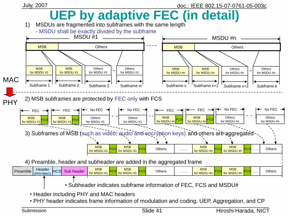
3) Subframes of MSB (such as video, audio and encryption keys) and others are aggregated
UEP by adaptive FEC (in detail)
MAC
MSB Others
PHY
MSDU #1
MSB
for MSDU #1
MSB
for MSDU #1
Others
for MSDU #1
Subframe 1 Subframe 2 Subframe m
Others
for MSDU #1
Subframe 3
MSB
for MSDU #n
MSB
for MSDU #n
Others
for MSDU #n
Subframe x Subframe x+1 Subframe k
Others
for MSDU #n
Subframe x+3
MSB Others
MSDU #n
MSB
for MSDU #1FCS
FEC
MSB
for MSDU #1FCS
FEC
Others
for MSDU #1
No FEC
Others
for MSDU #1
No FEC
MSB
for MSDU #nFCS
FEC
MSB
for MSDU #nFCS
FEC
Others
for MSDU #n
No FEC
Others
for MSDU #n
No FEC
MSB
for MSDU #1
MSB
for MSDU #1OthersFCS
MSB
for MSDU #n
MSB
for MSDU #nOthersFCS FCS…… ……FCS
Header(PHY/MAC)
Preamble HCSMSB
for MSDU #1
MSB
for MSDU #1OthersFCS
MSB
for MSDU #n
MSB
for MSDU #nOthersFCS FCS…… ……FCSSub header
2) MSB subframes are protected by FEC only with FCS
4) Preamble, header and subheader are added in the aggregated frame
• Subheader indicates subframe information of FEC, FCS and MSDU#
• Header including PHY and MAC headers
• PHY header indicates frame information of modulation and coding, UEP, Aggregation, and CP
1) MSDUs are fragmented into subframes with the same length
- MSDU shall be exactly divided by the subframe
doc.: IEEE 802.15-07-0761-05-003c
Submission Slide 42
July, 2007
Hiroshi Harada, NICT
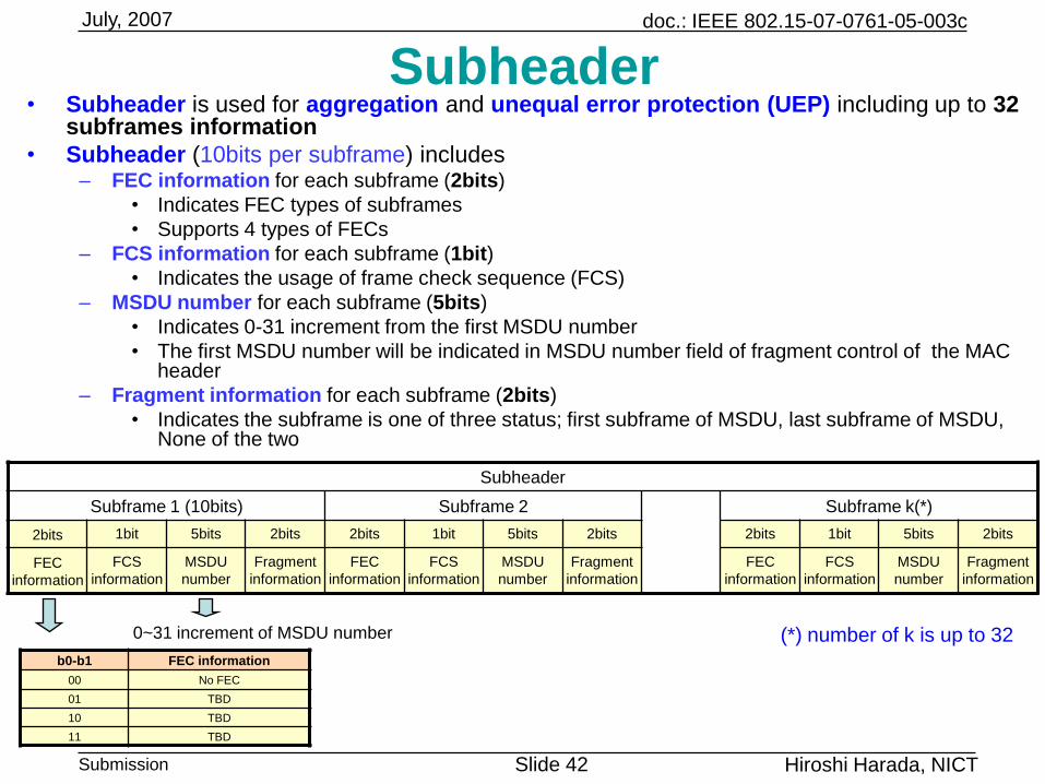
Subheader• Subheader is used for aggregation and unequal error protection (UEP) including up to 32
subframes information
• Subheader (10bits per subframe) includes– FEC information for each subframe (2bits)
• Indicates FEC types of subframes
• Supports 4 types of FECs
– FCS information for each subframe (1bit)
• Indicates the usage of frame check sequence (FCS)
– MSDU number for each subframe (5bits)
• Indicates 0-31 increment from the first MSDU number
• The first MSDU number will be indicated in MSDU number field of fragment control of the MAC header
– Fragment information for each subframe (2bits)
• Indicates the subframe is one of three status; first subframe of MSDU, last subframe of MSDU, None of the two
b0-b1 FEC information
00 No FEC
01 TBD
10 TBD
11 TBD
0~31 increment of MSDU number
Subheader
Subframe 1 (10bits) Subframe 2 Subframe k(*)
2bits 1bit 5bits 2bits 2bits 1bit 5bits 2bits 2bits 1bit 5bits 2bits
FEC
information
FCS
information
MSDU
number
Fragment
information
FEC
information
FCS
information
MSDU
number
Fragment
information
FEC
information
FCS
information
MSDU
number
Fragment
information
(*) number of k is up to 32
doc.: IEEE 802.15-07-0761-05-003c
Submission Slide 43
July, 2007
Hiroshi Harada, NICT
4343
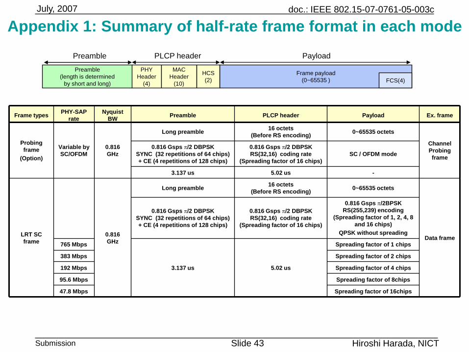
Appendix 1: Summary of half-rate frame format in each mode
Spreading factor of 8chips95.6 Mbps
Frame typesPHY-SAP
rate
Nyquist
BWPreamble PLCP header Payload Ex. frame
Probing
frame
(Option)
Variable by
SC/OFDM
0.816
GHz
Long preamble16 octets
(Before RS encoding)0~65535 octets
Channel
Probing
frame
0.816 Gsps p/2 DBPSK
SYNC (32 repetitions of 64 chips)
+ CE (4 repetitions of 128 chips)
0.816 Gsps p/2 DBPSK
RS(32,16) coding rate
(Spreading factor of 16 chips)
SC / OFDM mode
3.137 us 5.02 us -
LRT SC
frame
0.816
GHz
Long preamble16 octets
(Before RS encoding)0~65535 octets
Data frame
0.816 Gsps p/2 DBPSK
SYNC (32 repetitions of 64 chips)
+ CE (4 repetitions of 128 chips)
0.816 Gsps p/2 DBPSK
RS(32,16) coding rate
(Spreading factor of 16 chips)
0.816 Gsps p/2BPSK
RS(255,239) encoding
(Spreading factor of 1, 2, 4, 8
and 16 chips)
QPSK without spreading
765 Mbps
3.137 us 5.02 us
Spreading factor of 1 chips
383 Mbps Spreading factor of 2 chips
192 Mbps Spreading factor of 4 chips
47.8 Mbps Spreading factor of 16chips
PLCP header Payload
Preamble
(length is determined
by short and long)
PHY
Header
(4)
Frame payload
(0~65535 )
MAC
Header
(10)
HCS
(2) FCS(4)
Preamble
doc.: IEEE 802.15-07-0761-05-003c
Submission Slide 44
July, 2007
Hiroshi Harada, NICT
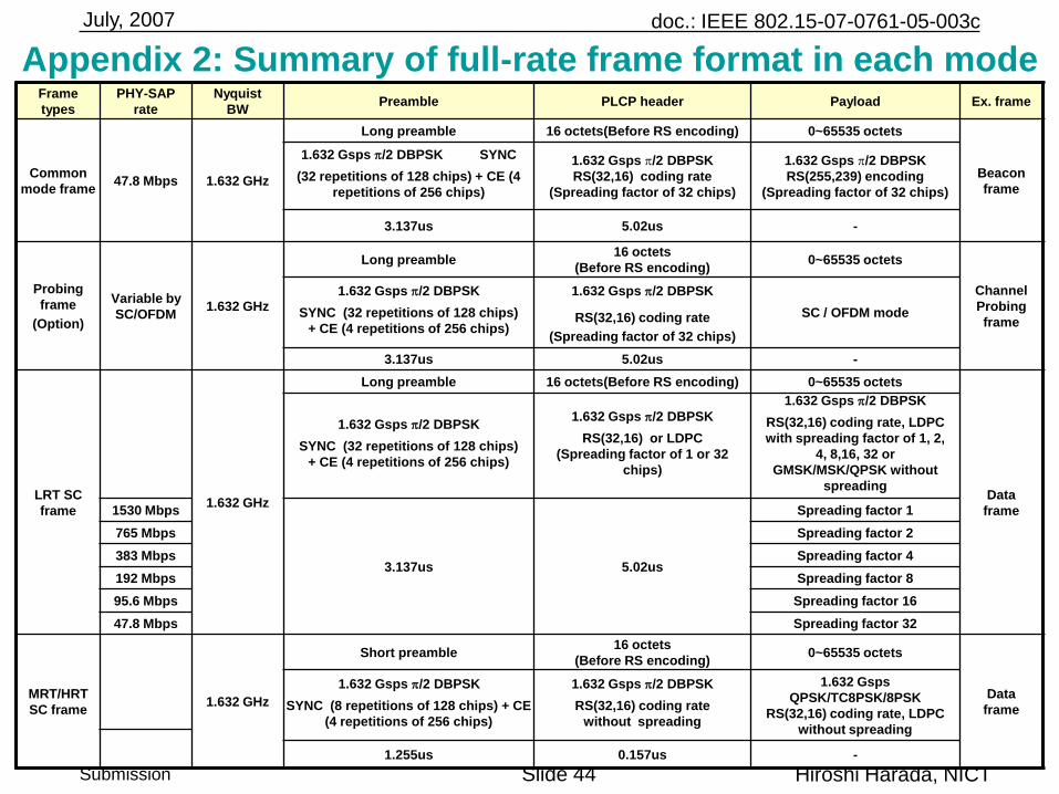
Frame
types
PHY-SAP
rate
Nyquist
BWPreamble PLCP header Payload Ex. frame
Common
mode frame47.8 Mbps 1.632 GHz
Long preamble 16 octets(Before RS encoding) 0~65535 octets
Beacon
frame
1.632 Gsps p/2 DBPSK SYNC
(32 repetitions of 128 chips) + CE (4
repetitions of 256 chips)
1.632 Gsps p/2 DBPSK
RS(32,16) coding rate
(Spreading factor of 32 chips)
1.632 Gsps p/2 DBPSK
RS(255,239) encoding
(Spreading factor of 32 chips)
3.137us 5.02us -
Probing
frame
(Option)
Variable by
SC/OFDM1.632 GHz
Long preamble16 octets
(Before RS encoding)0~65535 octets
Channel
Probing
frame
1.632 Gsps p/2 DBPSK
SYNC (32 repetitions of 128 chips)
+ CE (4 repetitions of 256 chips)
1.632 Gsps p/2 DBPSK
RS(32,16) coding rate
(Spreading factor of 32 chips)
SC / OFDM mode
3.137us 5.02us -
LRT SC
frame1.632 GHz
Long preamble 16 octets(Before RS encoding) 0~65535 octets
Data
frame
1.632 Gsps p/2 DBPSK
SYNC (32 repetitions of 128 chips)
+ CE (4 repetitions of 256 chips)
1.632 Gsps p/2 DBPSK
RS(32,16) or LDPC
(Spreading factor of 1 or 32
chips)
1.632 Gsps p/2 DBPSK
RS(32,16) coding rate, LDPC
with spreading factor of 1, 2,
4, 8,16, 32 or
GMSK/MSK/QPSK without
spreading
1530 Mbps
3.137us 5.02us
Spreading factor 1
765 Mbps Spreading factor 2
383 Mbps Spreading factor 4
192 Mbps Spreading factor 8
95.6 Mbps Spreading factor 16
47.8 Mbps Spreading factor 32
MRT/HRT
SC frame1.632 GHz
Short preamble16 octets
(Before RS encoding)0~65535 octets
Data
frame
1.632 Gsps p/2 DBPSK
SYNC (8 repetitions of 128 chips) + CE
(4 repetitions of 256 chips)
1.632 Gsps p/2 DBPSK
RS(32,16) coding rate
without spreading
1.632 Gsps
QPSK/TC8PSK/8PSK
RS(32,16) coding rate, LDPC
without spreading
1.255us 0.157us -
Appendix 2: Summary of full-rate frame format in each mode
doc.: IEEE 802.15-07-0761-05-003c
Submission Slide 45
July, 2007
Hiroshi Harada, NICT
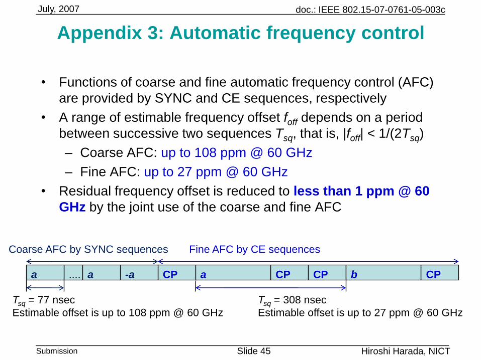
Appendix 3: Automatic frequency control
• Functions of coarse and fine automatic frequency control (AFC)
are provided by SYNC and CE sequences, respectively
• A range of estimable frequency offset foff depends on a period
between successive two sequences Tsq, that is, |foff| < 1/(2Tsq)
– Coarse AFC: up to 108 ppm @ 60 GHz
– Fine AFC: up to 27 ppm @ 60 GHz
• Residual frequency offset is reduced to less than 1 ppm @ 60
GHz by the joint use of the coarse and fine AFC
CP-a....
Coarse AFC by SYNC sequences Fine AFC by CE sequences
aa CPa CP CPb
Tsq = 77 nsec
Estimable offset is up to 108 ppm @ 60 GHz
Tsq = 308 nsec
Estimable offset is up to 27 ppm @ 60 GHz
doc.: IEEE 802.15-07-0761-05-003c
Submission Slide 46
July, 2007
Hiroshi Harada, NICT
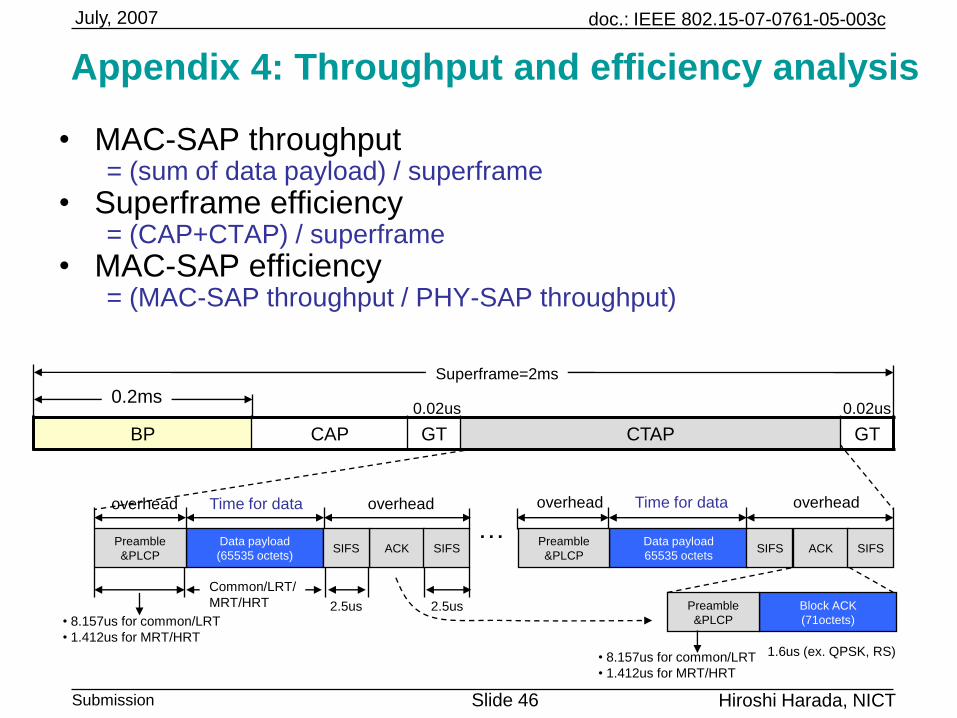
Appendix 4: Throughput and efficiency analysis
• MAC-SAP throughput = (sum of data payload) / superframe
• Superframe efficiency= (CAP+CTAP) / superframe
• MAC-SAP efficiency= (MAC-SAP throughput / PHY-SAP throughput)
BP CAP GT CTAP GT
0.02us 0.02us
Superframe=2ms
Data payload
(65535 octets)
Preamble
&PLCPACKSIFS SIFS
Data payload
65535 octets
Preamble
&PLCPACKSIFS SIFS
…Time for data overheadoverhead
0.2ms
Time for data overheadoverhead
• 8.157us for common/LRT
• 1.412us for MRT/HRT
2.5us 2.5us Block ACK
(71octets)
Preamble
&PLCP
Common/LRT/
MRT/HRT
1.6us (ex. QPSK, RS)• 8.157us for common/LRT
• 1.412us for MRT/HRT
![Project: IEEE P802.15 Working Group for Wireless Personal ......Voice:[+914-945-2598], E-Mail:[avaldes@us.ibm.com] Re: [In response to TG3c Call for Proposals (IEEE P802.15-07-0586-02-003c)]](https://img.pdfslide.us/doc/110x75/5f0b471c7e708231d42fb950/project-ieee-p80215-working-group-for-wireless-personal-voice914-945-2598.jpg)