Embed Size (px)
Citation preview
MAWPHU-II HYDRO ELECTRIC PROJECT(85 MW)
APRIL. 2016
PRE FEASIBILITY REPORT
MAPHU-II HYDRO ELECTRIC PROJECT (85MW)
MAWPHU-II HYDRO ELECTRIC PROJECT (85MW)
PRE-FEASIBILITY REPORT
i
TABLE OF CONTENTS
CHAPTER - I: EXECUTIVE SUMMARY
A. INTRODUCTION ……………………………………………………………………………..... 1
B. LOCATION OF THE PROJECT ………………………………….…………………………… 1
C. HYDROLOGY ……………….…………………………………………………………………..... 1
D. GEOLOGY ………………………………………………………………………………………. 3
E. POWER POTENTIAL STUDIES ……………………………….……………………………… 5
F. PROPOSED LAYOUT OF THE PROJECT ……………………………………………………. 5
G. CLIMATE ………………………………………………………………….……………………… 6
H. ELECTRO-MECHNICAL EQUIPMENTS ……………………………………………………. 6
I. POWER EVACUATION SYSTEM …………………………………………………………….. 7
J. CONSTRUCTION SCHEDULE ………………………………..……………………………… 7
K. ENVIRONMENTAL ASPECTS ……………………………………………………………… 7
L. ESTIMATE OF THE COST ……………………………………………………………………… 7
M. FINANCIAL ANALYSIS ……………………………………………………………………… 8
N. SALIENT FEATURES …………………………………………………………………………… 9
CHAPTER - II: BACKGROUND INFORMATION
2.1 GENERAL …………………………………………………………………………………… 16
2.2 POWER SCENARIO IN NORTH EASTERN REGION ………………………………….. 16
2.3 DEVELOPMENT OF HYDRO POWER DEMAND …………………………………………. 19
2.4 NECESSITY OF THE PROJECT ………………………..………………………………… 20
CHAPTER - III: THE PROJECT AREA
3.1 GENERAL …………………………………………………………………………………… 22
3.2 PROJECT BACKGROUND …………………………………………………………………… 23
3.3 ALTERNATIVE STUDIES …………………………………………………………………… 25
3.3.1 ALTERNATIVE LOCATIONS OF DAM …………………………………………………… 25
3.3.1.1 OLD PFR LOCATION …………….………………………………………………………….. 26
3.3.1.2 ALTERNATIVE - 1 ………………………………….…………………………………………….. 27
3.3.1.3 ALTERNATIVE - 2 …………………….………………………………………………………….. 28
3.3.1.4 ALTERNATIVE - 3 ...……………………………………………………………………………… 28
3.3.1.5 ALTERNATIVE - 3A ………………………………………………………………………… 30
3.4 UPDATED PFR WITH REVISED INSTALLED CAPACITY OF 85MW ………………… 30
3.5 BASIN CHARACTERISTICS ……………..…………………………………………………… 31
3.6 CLIMATE …………………………….………………………………………………………….. 32
3.7 SOCIO-ECONOMIC PROFILE ………………………..……………………………………….. 32
CHAPTER - IV: TOPOGRAPHIC AND GEOTECHNICAL ASPECTS
4.1 GENERAL ………………………………….…………………………………………………….. 37
MAPHU-II HYDRO ELECTRIC PROJECT (85MW)
MAWPHU-II HYDRO ELECTRIC PROJECT (85MW)
PRE-FEASIBILITY REPORT
ii
4.2 TOPOGRAPHY AND MAPPING .………………………………………………………….. 37
4.2.1 EXISTING TOPOGRAPHIC INFORMATION ……………………………………….……..... 37
4.2.2 TOPOGRAPHICAL FIELD SURVEYING ……………………………………..………………. 37
4.2.3 BATHYMETRIC SURVEY ………………………..…………………………………………… 40
4.3 SITE INVESTIGATION AND GEOLOGY ………………………………………………….. 41
4.3.1 INTRODUCTION …………………..………….……………………………………………….. 41
4.3.2 GEOLOGY OF THE PROJECT AREA ………………………………………..…………….. 41
4.3.3 FIELD INVESTIGATIONS ………………………………………………….……………….. 42
4.3.3.1 ALTERNATIVE DAM SITES …………………..…………………………………………….. 42
4.3.3.2 GEOLOGICAL MAPPING ………………………………………..……………………….. 45
4.3.3.3 DRILLING …………………………………………………………….………………………….. 46
4.3.3.4 WATER PRESSURE/ PERMEABILITY TESTS ………………………………………….. 48
4.3.3.5 SPT ……………………………………..…………..…………………………………………….. 48
4.3.3.6 GROUTABILITY TEST ………..……………………………..……………………….. 48
4.3.3.7 EXPLORATORY DRIFTING ……………………………………….………………………….. 48
4.3.3.8 ROCK MECHANIC TESTS …………………………..……………………………………….. 48
4.3.3.9 PETROGRAPHY ……………………..…………..…………………………………………….. 53
4.3.3.10 GEOPHYSICAL STUDIES …………..……………………………..……………………….. 53
4.3.3.11 SEISMOLOGICAL STUDIES ……………………………………….………………………….. 53
4.4 GEOTECHNICAL EVALUATION OF CIVIL STRUCTURES …………………………….. 53
4.4.1 DAM …………………………………..…………..…………………………………………….. 53
4.4.2 ENERGY DISSIPATOR ………….………..……………………………..……………………….. 55
4.4.3 COFFER DAM ……………………………………………………….………………………….. 55
4.4.3.1 UPSTREAM COFFER DAM ………………………………..………………………….. 55
4.4.3.2 DOWNSTREAM COFFER DAM …..…………..…………………………………………….. 56
4.4.4 DIVERSION TUNNEL ………….………..……………………………..……………………….. 56
4.4.4.1 DT INLET AREA ………………………………………………….………………………….. 56
4.4.4.2 DT INTERMEDIATE AREA ………………………………..………………………….. 57
4.4.4.3 DT OUTLET AREA ……………….…………..…………………………………………….. 57
4.4.5 POWER INTAKE ………….………..……………………………..……………………….. 57
4.4.6 HEAD RACE TUNNEL …………………………………………….………………………….. 58
4.4.6.1 REACH I (RD 0 – 700M) ………………….………………………..………………………….. 59
4.4.6.2 REACH II (RD 700– 1165M) …………………..…………………………………………….. 59
4.4.6.3 REACH III (RD 1165 -1640 M) ………………………………………..……………………….. 60
4.4.6.4 REACH IV (RD 1640 - 2240 M) …………..……………………….………………………….. 60
4.4.6.5 REACH V (RD 2240-2620 M) …………….………………………..………………………….. 61
4.4.6.6 CONCLUSION …………………..……………..…………………………………………….. 61
4.4.7 SURGE SHAFT ………………….…………………………………..……………………….. 62
4.4.8 PRESSURE SHAFT …………………….…..……………………….………………………….. 63
4.4.8.1 TOP HORIZONTAL PRESSURE SHAFT ………………………..………………………….. 64
4.4.8.2 VERTICAL PRESSURE SHAFT ……………..…………………………….. 64
MAPHU-II HYDRO ELECTRIC PROJECT (85MW)
MAWPHU-II HYDRO ELECTRIC PROJECT (85MW)
PRE-FEASIBILITY REPORT
iii
4.4.8.3 BOTTOM HORIZONTAL PRESSURE SHAFT …………………..……………………….. 64
4.4.9 POWER HOUSE ………….…………….…..……………………….………………………….. 65
4.4.10 TAIL RACE CHANNEL …………………………….……………..………………………….. 67
4.4.11 CONSTRUCTION MATERIAL ………………………….………..…………………………….. 68
4.4.11.1 INTRODUCTION ………………………….……………..……………………….. 68
4.4.11.2 VARIOUS SOURCES OF CONSTRUCTION MATERIAL ……….………………………….. 69
CHAPTER - V: HYDROLOGY
5.1 GENERAL ………………………………….……………………………………………………... 72
5.2 THE PROJECT ………………………….………………………………………………………. 72
5.3 THE RIVER SYSTEM AND BASIN CHARACTERISTICS …………………………………. 72
5.4 THE CATCHMENT …….…………….….…………………………………………………… 74
5.4.1 HYPSOMETRY OF THE CATCHMENT ……………………………………………………... 76
5.4.2 ESTIMATION OF MEAN CATCHMENT ELEVATION …………….……………………. 77
5.4.3 EQUIVALENT SLOPE ……………………..…..…………………………………………... 77
5.4.4 L – SECTION OF RIVER UMIEW ………….…………………………………………………. 80
5.5 PROJECTS IN UMIEW RIVER – A GLANCE ………………………………………………... 80
5.5.1 GREATER SHILLONG WATER SUPPLY SCHEME (GSWSS) ………………………………. 80
5.5.2 MAWPHU STAGE I HEP (90 MW) …………………………..………………………………. 81
5.6 METEOROLOGICAL CHARACTERISTICS …………………………………………………… 82
5.6.1 CLIMATE ………………………………………………………………………………………... 82
5.6.2 RAINFALL ……………………………………………………….……….……………………. 82
5.6.3 TEMPARATURE & RELATIVE HUMIDITY ……..…………………………………………... 82
5.7 DATA AVAILABILITY …………………….…………………………………………………. 83
5.7.1 RAINFALL DATA ……………………………………..………………………………………... 83
5.7.2 GAUGE AND DISCHARGE DATA ………………………………..………………………. 83
5.8 ANALYSIS OF DATA ……………..…………………………..………………………………. 95
5.8.1 FILLING DATA GAPS …………………………………………………… 95
5.9 WATER AVAILABILITY STUDIES ………………………………………………………... 107
5.9.1 EXTENSION OF RAINFALL DATA …………………………….……….……………………. 107
5.9.2 RAINFALL-RUNOFF CORELATION …………..…………………………………………... 110
5.9.3 EXTENSION OF FLOW SERIES AT MAWPLANG ………………………………………. 113
5.9.4 ESTIMATION OF YEILD CORRECTION FACTOR ……………………………………... 114
5.9.5 DEVELOPMENT OF FLOW SERIES AT DAM SITE ………………..………………………. 114
5.10 DEPENDABILITY STUDIES ………..…………………………..………………………………. 115
5.11 DESIGN FLOOD STUDIES …………..…………………………………………………… 125
5.12 CLASSIFICATION OF DAMS ………………………………………………………... 125
5.13 DESIGN FLOOD CRITERIA ……………….…………………….……….……………………. 125
5.14 ESTIMATION OF DESIGN FLOOD …………..…………………………………………... 126
5.14.1 DEVELOPMENT OF SYNTHETIC UNIT HYDROGRAPH (SUG) ………………………. 126
5.14.2 DESIGN STORM ……………………………………………..…………………………………... 128
MAPHU-II HYDRO ELECTRIC PROJECT (85MW)
MAWPHU-II HYDRO ELECTRIC PROJECT (85MW)
PRE-FEASIBILITY REPORT
iv
5.14.3 TEMPORAL DISTRIBUTION ………………………..……………..………………………. 129
5.14.4 DESIGN LOSS RATE ……………..…..…………………………..………………………………. 131
5.14.5 DETERMINATION OF RAINFALL EXCESS ………………………………………… 131
5.14.6 BASE FLOW ……………………………..……………………………………………………... 132
5.14.7 CONVOLUTION OF DESIGN STORM WITH UG ………….……….……………………. 132
5.14.8 CONCLUSIONS AND RECOMMENDATIONS ……………………………………………... 133
5.15 DIVERSION FLOOD STUDIES ………………………………………………………………. 133
5.16 DESIGN CRITERIA ………………………………………………………………. 133
5.17 DATA UTILIZED ……………………………………………..…………………………………... 134
5.18 METHODOLOGY ADOPTED ………………………..……………..………………………. 135
5.19 SEDIMENTATION STUDIES …..…………………………..………………………………. 136
5.20 ELEVATION AREA CAPACITY …………………………….……………………………… 137
5.21 DATA REQUIREMENT ……………..……………………………………………………... 138
5.22 LONG TERM ANNUAL AVERAGE SEDIMENTATION RATE …….……………………. 138
5.23 CLASSIFICATION OF SEDIMENT PROBLEM ……………………………………………... 138
5.24 SEDIMENT MANAGEMENT MEASURES ……………………………………………………. 139
CHAPTER - VI: POWER POTENTIAL & INSTALLED CAPACITY
6.1 GENERAL …………………..………………………………………………………………….. 140
6.2 PROJECT PARAMETERS ….……………………………………………………………….. 140
6.3 HEAD COMPUTATION …………………………………………………………..…………. 141
6.4 WATER AVAILABILITY …………..…………………………………………………………. 141
6.5 DEPENDABLE FLOWS ………………………………………………..………………….. 141
6.6 FIRM POWER ………………………………………………………………………………….. 143
6.7 INSTALLED CAPACITY …….……….………………………………………………………… 143
6.7.1 RANGE OF INSTALLED CAPACITIES ……..………………..………………………………. 143
6.7.2 OPTIMUM INSTALLED CAPACITY …………………..…….………………………………... 144
6.8 50% DEPENDABLE YEAR ENERGY GENERATION ………………………………………. 146
6.9 DESIGN ENERGY …………………………………………………………. 146
6.10 ANNUAL PLANT LOAD FACTOR …………………………………………………………. 147
6.11 LEAN PERIOD LOAD FACTOR …………………………………………………………. 147
6.12 PEAKING OPERATION …………………………………………………………. 147
6.13 NUMBER OF UNITS …………………………………………………………. 147
6.14 SUMMARY …………………………………………………………. 148
6.15 LIST OF ANNEXURE …………………………………………………………. 148
CHAPTER - VII: DESIGN OF CIVIL AND HYDRO-MECHANICAL STRUCTURES
7.1 GENERAL …………………………………………………………………………………….. 157
7.2 PROPOSED LAYOUT OF THE PROJECT …………………………………………………... 157
7.3 DIFFERENT STRUCTURES ………………………………………………………………….. 158
7.3.1 DIVERSION TUNNEL …………….….…………….………………………………………….. 158
MAPHU-II HYDRO ELECTRIC PROJECT (85MW)
MAWPHU-II HYDRO ELECTRIC PROJECT (85MW)
PRE-FEASIBILITY REPORT
v
7.3.2 UPSTREAM COFFER DAM ……………….………………………………………………….. 158
7.3.3 DOWNSTREAM COFFER DAM …………….……..………………………………………….. 158
7.3.4 CONCRETE DIVERSION DAM ……………………………………………………………. 159
7.3.4.1 TYPE OF DAM ……………………..………………………………………………………... 159
7.3.4.2 DAM LAYOUT DETAILS ………………………………………………………… 160
7.3.4.3 SPILLWAY …………..……………………………………………………...…………………….. 161
7.3.5 POWER INTAKES ……………………………….………………………………………………. 162
7.3.6 HEAD RACE TUNNEL ………………………………………………………………. 164
7.3.7 REQUIREMENT OF SURGE SHAFT ………………………………………………………..…. 167
7.3.8 PRESSURE SHAFT ………………………………………………………………………….…… 170
7.3.9 POWER HOUSE ……………………………………………….…………. 173
7.4 HYDRO-MECHANICAL WORKS ……………………………………………….…………. 176
7.4.1 GATES AND PENSTOCKS ………………………………………………….……………… 176
7.4.1.1 SCOPE ………………………………………………….……………… 176
7.4.1.2 DIVERSION TUNNEL GATE: (8.0M X 8.0M -1 NO.) …………….……………… 176
7.4.1.3 STOPLOGS FOR SLUICE SPILLWAY RADIAL GATES …………….……………… 177
7.4.1.4 SLUICE SPILLWAY RADIAL GATES: (8.0M X 11.5M - 5NOS.) ……………….……. 179
7.4.1.5 INTAKE TRASH RACKS (5.0M X 2.0M -2SETS/20 PANELS) ………………….……. 180
7.4.1.6 TRASH RACK CLEANING MACHINE (TRCM) …………………………..…………. 181
7.4.1.7 INTAKE EMERGENCY GATE: (4.8M X 4.8M – 1NO.) ……………………………………... 182
7.4.1.8 INTAKE SERVICE GATE: (4.8M X 4.8M – 1NO.) ……………………………….………... 183
7.4.1.9 SURGE SHAFT GATES: (3.5M X 3.5M - 1NO.) ………………………….……………….… 184
7.4.1.10 STEEL LINED PRESSURE SHAFT ……………………………………..…………………. 185
7.4.1.11 DRAFT TUBE GATES: (3.75M X 2.35M - 2NOS.) …………………….……………………... 186
CHAPTER - VIII: DESIGN OF ELECTRO-MECHANICAL WORKS
8.1 GENERAL …………………………………………………………………………………….. 189
8.2 TURBINE ……………..……………………………………………………. 189
8.3 GENERATORS ………………………………………………………………… 191
8.4 AUXILIARY ELECTRICAL SERVICES ………….……………………………. 192
8.4.1 MAIN STEP UP TRANSFORMERS ……….……………………………………. 192
8.4.2 GENERATOR – TRANSFORMER CONNECTIONS ……………………………………….. 192
8.4.3 145KV GAS INSULATED SWITCHGEAR ………….…………………………………………. 193
8.4.4 145KV XLPE CABLES ………………………………………….………..…………………… 193
8.4.5 CONTROL AND MONITORING SYSTEM …..………..…………………………………. 194
8.4.6 PROTECTION SYSTEM ……………………………………………………………………… 195
8.4.7 AC AUXILIARY POWER SYSTEM ……………..………………………………………. 196
8.4.7.1 POWER TO DAM SITE AREA ………………………………... 196
8.4.7.2 POWER TO PENSTOCK PROTECTION VALVE HOUSE ………………………………. 197
8.4.7.3 POWER TO COLONY AND OFFICE AREA ………….…………………………………….. 197
8.4.8 DC AUXILIARY SERVICES ……………………………………………………………... 197
MAPHU-II HYDRO ELECTRIC PROJECT (85MW)
MAWPHU-II HYDRO ELECTRIC PROJECT (85MW)
PRE-FEASIBILITY REPORT
vi
8.4.9 EARTHING SYSTEM …………………..……………………………………………………... 197
8.4.10 POWER, CONTROL AND INSTRUMENTATION CABLES ……………………………….. 198
8.4.11 ILLUMINATION SYSTEM …………………………………………………………………. 198
8.4.12 TEST LABORATORY ………………………………….…………………………… 199
8.4.13 COMMUNICATION SYSTEM …………………………..………………………………. 199
8.5 AUXILIARY MECHANICAL SERVICES ……………………………………………….. 199
8.5.1 COOLING WATER SYSTEM ……………………………………………………………... 200
8.5.2 DRAINAGE AND DEWATERING SYSTEMS ………………………………………………... 200
8.5.3 FIRE PROTECTION …………………………………………….………………………….. 201
8.5.4 HEATING,VENTILATION AND AIR CONDITIONING(HVAC) ………………… 202
8.5.5 COMPRESSED AIR SYSTEM ………………………………….…………………………… 203
8.5.6 ELECTRICAL LIFTS AND ELEVATORS ……………..………………………………. 203
8.5.7 WORKSHOP EQUIPMENT ……………………………………………….. 203
8.6 POWER EVACUATION ARRANGEMENT ……………………………………………….. 204
CHAPTER - IX: INFRASTRUCTURE FACILITIES
9.1 GENERAL ………………………………………………………...…………………………….. 205
9.2 TRANSPORTATION ………………………….….……………..…………………………….. 205
9.3 CONSTRUCTION FACILITIES …………..……………………….………………………….. 205
9.3.1 PROJECT ROADS INCLUDING TEMPORARY/ PERMANENT BRIDGES ……………. 206
9.3.2 SITE OFFICES AND RESIDENTIAL/ NON-RESIDENTIAL COMPLEXES ……………….. 207
9.3.2.1 SITE OFFICES …………………………………………………………………………………….. 207
9.3.2.2 RESIDENTIAL ACCOMODATION AT PROJECT SITE ………..……………………….. 207
9.3.2.3 NON-RESIDENTIAL COMPLEXES AT PROJECT SITE …………………….…………….. 208
9.3.3 WORKSHOPS ………………………………………………………………..………………. 208
9.3.4 WAREHOUSES/ STORES COMPLEX …………………………….……………….. 208
9.3.5 MUCK DISPOSAL AREA …………………………………………….. 208
9.3.6 EXPLOSIVE MAGAZINE …………………………………………………………….. 209
9.3.7 CONSTRUCTION PLANT FACILITIES ……………………………….. 209
9.3.7.1 CRUSHING PLANT …………………………….……………..…………….. 209
9.3.7.2 BATCHING AND MIXING PLANT …………………………….……..…………………….. 209
9.3.8 LAND REQUIREMENT ………...…………………..………………..……………………….. 210
9.3.9 CONSTRUCTION POWER …………..……………………………………….………………….. 211
9.3.10 TELECOMMUNICATION ………………..…..……………….. 212
9.3.11 WATER SUPPLY SYSTEM ………………………..…..…………. 212
9.3.12 SECURITY AND SAFETY ARRANGEMENT ………………………..…..…………. 212
9.3.12.1 SECURITY STAFF OFFICES AND CHECK POST ………………………..…..……….. 212
9.3.12.2 FIRE STATION ………………………..…..………….. 212
CHAPTER - X: CONSTRUCTION PLANNING
10.1 PROJECT COMPONENTS ………………….…….………………………..……………….. 213
MAPHU-II HYDRO ELECTRIC PROJECT (85MW)
MAWPHU-II HYDRO ELECTRIC PROJECT (85MW)
PRE-FEASIBILITY REPORT
vii
10.2 CLIMATIC CONDITIONS …………………………..………….……………………….. 213
10.3 ASSUMPTIONS WHILE FRAMING THE SCHEDULE ………..……………………………… 214
10.4 SCHEDULE OF WORK …………………………..……………………………… 214
10.4.1 RIVER DIVERSION WORKS ………………………………………………..……………….. 214
10.4.2 DAM AND SPILLWAYS ……………….…………………………..……………….. 216
10.4.3 HEAD RACE TUNNELS AND ADITS ……………………………………..……………….. 219
10.4.4 POWER HOUSE ……………………………..……………………………..……………….. 221
CHAPTER - XI: ENVIRONMENT AND ECOLOGY
11.1 INTRODUCTION ……………………………………………………………………………….. 222
11.2 ENVIRONMENTAL BASELINE SETTING ………………………………………………….. 222
11.2.1 PHYSIO-CHEMICAL ASPECTS …………………………………………………….. 222
11.2.2 ECOLOGICAL ASPECTS …………………………………………………………………….. 223
11.2.3 SOCIO-ECONOMIC ASPECTS ………………………………………………………………….. 226
11.3 PREDICTION OF IMPACTS ………….……………………………………… 227
11.4 IMPACTS ON LAND ENVIRONMENT ……………………………………………….. 227
11.5 IMPACTS ON WATER RESOURCES …………………………………………. 230
11.6 IMPACTS ON WATER QUALITY …………………………………………………………… 230
11.7 IMPACT ON TERRESTRIAL FLORA …………………………………………………….. 231
11.8 IMPACTS ON TERRESTRIAL FAUNA …………………………………………………….. 233
11.9 IMPACTS ON AQUATIC ECOLOGY …………………………………………………….. 233
11.10 IMPACTS ON NOISE ENVIRONMENT ………………………………………………….. 234
11.11 AIR POLLUTION ……………………………………………….. 234
11.12 IMPACTS ON SOCIO-ECONOMIC ENVIRONMENT …………………………………….. 234
11.13 SUMMARY OF IMPACTS AND EMP ……………………………………………………….. 235
CHAPTER - XII: PRELIMINARY COST ESTIMATE
12.1 GENERAL ……………..………………………………………………………………………….. 239
12.2 BASIC ESTIMATE ………………………………………………………….……….………….. 239
12.2.1 GENERAL ……..…………………………………………………………………………….. 239
12.2.2 TAXES AND DUTIES …………….………………………………………………………… 239
12.2.3 I - WORKS ………………………..……………….……………………………………………. 239
12.2.4 A - PRELIMINARY ………..……….………………………………………………………….. 239
12.2.5 B - LAND ………………..………………………………………………………………………. 239
12.2.6 C - WORKS ……..…………………………………………………………………………….. 240
12.2.7 J - POWER PLANT CIVIL WORKS ……………………………………………………………… 240
12.2.8 K - BUILDINGS …………………………..……….……………………………………………. 240
12.2.9 M - PLANTATION ………..…………………………………………………………….. 240
12.2.10 O - MISCELLANEOUS …………………………………………………………………………. 240
12.2.11 P - MAINTENANCE DURING CONSTRUCTION & Y- LOSSES ON STOCK ……..…….. 241
12.2.12 Q - SPECIAL TOOLS AND PLANT ………………….…………………………………… 241
MAPHU-II HYDRO ELECTRIC PROJECT (85MW)
MAWPHU-II HYDRO ELECTRIC PROJECT (85MW)
PRE-FEASIBILITY REPORT
viii
12.2.13 R - COMMUNICATION ………………….……………………………………………. 241
12.2.14 X - ENVIRONMENT AND ECOLOGY ………..…………………………………………….. 241
12.2.15 Y - LOSSES ON STOCK ………………………………………………………………………. 241
12.2.16 ELECTRICAL WORKS AND GENERATING PLANT …….…………………………….. 241
12.2.17 II - ESTABLISHMENT …………………………………………………………………………… 241
12.2.18 III - TOOLS AND PLANTS ………………….……………………………………………. 242
12.2.19 IV - SUSPENSE ………..………………………………………………………………………. 242
12.2.20 V - RECEIPTS AND RECOVERIES ………………………………………………………. 242
CHAPTER - XIII: ECONOMIC AND FINANCIAL EVALUATION
13.1 GENERAL ………………………………………………………………………………………….. 244
13.2 PROJECT COST …..……………………………………………………………………………… 244
13.3 PHASING OF COST ……….……………………………………………………………………… 245
13.4 ESCALATION IN COST ……….…………………………………………………………………. 245
13.5 FINANCING …………………….…………………………………………………………………. 245
13.6 ENERGY BENEFITS ……………………………………………………………………………. 245
13.7 ENERGY SALE PRICE ……………………………………………………………………. 246
13.8 THE ASSUMPTIONS TAKEN FOR WORKING OUT THE TARIFF ……..………………... 246
13.8.1 PROJECT LIFE …………………………………………………………………………………... 246
13.8.2 INTEREST RATE …………………………………………………………………………………. 246
13.8.3 RETURN ON EQUITY …………………………………………………………………………... 246
13.8.4 DEPRECIATION ……………..………………………………………………………………… 246
13.8.5 OPERATION AND MAINTENANCE CHARGES ………….………………………………… 246
13.8.6 INTEREST ON WORKING CAPITAL …………………..…………………………………….. 246
13.8.7 AUXILIARY AND TRANSFORMATION LOSSES …….……………………………………… 247
13.8.8 OTHER MISCELLANEOUS ASSUMPTIONS ……….………………………………………… 247
13.8.9 TARIFF COMPUTATION …………………….………………………………………………….. 247

CHAPTER - I
EXECUTIVE SUMMARY
MAWPHU-II HYDRO ELECTRIC PROJECT (85MW)
MAWPHU-II HYDRO ELECTRIC PROJECT (85MW)
PRE-FEASIBILITY REPORT
Page: 1
CHAPTER I
EXECUTIVE SUMMARY
A. INTRODUCTION
Mawphu Hydro Electric Project, Stage - II is proposed as a run-of-river scheme on the
river Umiew in East Khasi Hills District of Meghalaya. The proposed dam site is located
at about 3.17km downstream of Umduna HEP (90 MW) Power House location and the
Power House site is located at about 2km downstream of Thieddieng village on the right
bank of the river. The project is being implemented by North Eastern Electric Power
Corporation Ltd, a Government of India enterprise. Environmental Clearance for pre-
construction activities along with approved TOR was accorded by MoEF&CC in May
2014. This clearance was obtained with project installed capacity of 75MW and other
associated parameters. EIA/EMP studies have been carried out and completed based on
above stated TOR. In the meantime, installed capacity of the project has undergone
upward revision to 85MW as per recommendation of CEA. Project parameters have
remained unaltered with the above change in installed capacity barring changes in
Power House dimensions, Design Energy & Turbine-Generators. Instant PFR has been
prepared based on revised installed capacity of 85MW.
B. LOCATION OF THE PROJECT
Mawphu HEP, Stage - II is located on the Umiew river in East Khasi Hills district
of Meghalaya. The proposed dam site is located at latitude 25°18’32”N and longitude
91°38’19”E. The project area can be accessed from Guwahati airport, which is at about 120
km from Shillong, the capital of Meghalaya. The nearest rail head is located at Guwahati.
State Highway is available from Shillong to reach Mawsynram, which is a small town at
about 60km from Shillong. Mawsynram is connected with Thieddieng village through
about 6km foot track. Road is also existing from Mawsynram towards Thieddieng for
about 4km and the same is under construction. The dam site can be accessed from
Thieddieng (at about 2km) through footpath. The power house site is also accessed from
Thieddieng village (at about 2km) through footpath.
C. HYDROLOGY
i) Water Availability studies
MAWPHU-II HYDRO ELECTRIC PROJECT (85MW)
MAWPHU-II HYDRO ELECTRIC PROJECT (85MW)
PRE-FEASIBILITY REPORT
Page: 2
Available rainfall data at Shillong and Mawphlang along with observed discharge data at
Mawphlang dam site from January 1979 to December 1987 was utilized for water
availability studies. Gaps in the available rainfall and discharge data at Mawphlang filled.
Consistency checks on the data were applied. Available discharges at Mawphlang for the
period 1979-80 to 1987-88 extended up to 2004-05 using rainfall-runoff relations. Based on
TRMM data for the period 1998-2009, catchment rainfall worked out to 4415 mm.
Adopting runoff factor of 0.8, runoff at Mawphu II dam site comes to 3538 mm. Mean
annual runoff at Mawphlang based on observed data is 3018 mm. Hence yield correction
factor for dam site comes to 1.17. The discharges at dam site were estimated by increasing
Mawphlang discharges in catchment proportion and by applying yield correction factor.
Considering the withdrawal by GSWSS, available 10-daily discharges at dam site
determined by subtracting 0.5 cumecs from the 10-daily estimated discharges at the dam
site, to obtain the available discharges for the period 1979-80 to 2004-05. From the 10-daily
discharges at dam site, annual flows for the period 1979-80 to 2004-05 worked out and
arranged in descending order. % Age dependability estimated using Weibull’s equation.
90 % & 50 % dependable flows worked out as 887 & 1020 MCM, which correspond to the
years 1996-97 & 2002-03 respectively. 10-Daily flows during 90 % dependable year (1996-
97) have been used for power potential studies. Water availability studies have been
examined and approved by CWC vide U. O. No. 4/161/2013-Hyd (NE)/104-05 dated
11/03/14.
ii) Design Flood Studies:
As per BIS guidelines dams with gross storage capacity greater than 60 MCM or
hydraulic height greater than 30 m are to be designed to safely pass Probable Maximum
Flood (PMF).Since height of the dam is more than 30 m, the project is designed to safely
pass the PMF. Synthetic UG at the dam site was estimated from the basin characteristics
viz. A, L, Lc, S, etc., using report for “Estimation of Design Flood for South Bank
Tributaries of the Brahmaputra, Sub-zone 2 (b)”. Since time to peak worked out as 10.1
hours which appeared to be on the higher side for a catchment area of 308 sq km and
having steep slope. Hence as advised by CWC, time of concentration has been estimated
using Kirpch formula, California formula etc., which worked out to about 5 hours.
Synthetic UG was therefore developed using Sub-Zone 2 (a) report of CWC and
convoluted with 1-day PMP given by IMD. From above, design flood of 9,970 cumecs has
been adopted.
MAWPHU-II HYDRO ELECTRIC PROJECT (85MW)
MAWPHU-II HYDRO ELECTRIC PROJECT (85MW)
PRE-FEASIBILITY REPORT
Page: 3
iii) Diversion Flood:
As per IS - 14815:2000 for planning river diversion works for concrete dams, 1 in 25 year
flood of non-monsoon months or maximum observed during these months; whichever is
higher, is to be considered. From the available daily discharges of River Umiew at
Mawphlang (C.A. = 115 sq km) for the period 1980-81 to 1996-97, non-monsoon peaks
were worked out. The annual peaks thus obtained were subjected to frequency analysis to
determine the floods for various return periods. It is seen that 25 yr return period flood at
Mawphlang works out to 154 cumecs which is less than the observed non-monsoon flood
of 174 cumecs. Hence, as per IS -14815:2000, diversion flood at Mawphlang comes to 174
cumecs. Transforming this flood using Dicken’s equation, the diversion flood at Mawphu
HEP, stage II works out to 375 cumecs.
iv) Sedimentation Studies:
Based on the topographical survey of the reservoir areas and capacities at various
elevations have been worked out. Since sedimentation observation of Umiew river at the
project site or at any other site in the vicinity are not available, sediment rate of 1mm/sq
km/yr has been adopted for the studies. From the capacity inflow ratio, trap efficiency
from Brune’s curve works out to 0.5%, which indicates that most of the sediment will not
be trapped in the reservoir and would flow downstream. Hence following measures for
sediment management have been provided in the design aspects.
i) Operating the reservoir at MDDL during the monsoon months to route the
incoming sediment downstream of the project site.
ii) Provision of low level sluice spillway crest for flushing the silt downstream
during flood season.
iii) Reservoir drawdown flushing two times every year, to ensure that live storage is
always available.
iv) Adequate vertical separation between the water conductor intake sill level and the
sluice spillway crest level for effective silt flushing.
D. GEOLOGY
i) Geological set up of the Project Area
The project area falls in the central part of Meghalaya, where the Gneissic Complex has
multiple deformational & metamorphic episodes. In general, the grade of metamorphism
varies from the green schist to amphibolites facies. The Meghalaya plateau and the Mikir
MAWPHU-II HYDRO ELECTRIC PROJECT (85MW)
MAWPHU-II HYDRO ELECTRIC PROJECT (85MW)
PRE-FEASIBILITY REPORT
Page: 4
hills occur in between the E-W aligned Eastern Himalaya to the north and the broadly
NNESSW Indo-Myanmar mobile belt to the east. The Northern and North-eastern
boundary with Bengal basin lies to its south. These geological domains are separated
from the main Himalayan belt by the Brahmaputra alluvium. The Mikir Hills are
separated from the Meghalaya Plateau by the alluvium tract of Kopili River and the NE-
SW Kopili fault.Dauki fault is located 12 km south of project area.
ii) Field Investigations
In last couple of years, the Project components have been studied in detail through
� Geological mapping
� Exploratory drilling
� Drifting
� In-Situ Test and Laboratory test
� Petrography
� Groutability test
� Geophysical Survey
Geological mapping has been done in Dam and appurtenant structure, reservoir, HRT
Adit portals, Suege Shaft, Pressure Shaft and Pressure Shaft Adit, Power House and Tail
Race Channel in 1: 1000 scale. The same has been done in HRT in 1: 2500 scale.
In addition to 3 bore holes with aggregating length of 90m for Groutability test, 20 bore
holes having cumulative lengths of 950m have been drilled so far. Out of these 20 drill
holes, 12holes with cumulative length of 475m have been drilled to explore Dam and its
appurtenant structures and 2 holes of 50m & 60 m length were drilled to explore surface
Power house whereas 4 bore holes were drilled to explore pressure shaft and Surge shaft
was explored by one hole of 110m. 2 Drifts each with length of 30m has been done on
both abutments of the dam.
Laboratory rock-mechanics tests, geo-physical investigation,etc. have also been
completed for the project.
iii) Seismological studies
The project is located in North Eastern region of India which falls in Zone V of the seismic
zoning map of India and is considered to be seismically active region. Analysis of the
earthquake data obtained from different sources reveals that 137 major earthquakes
shocked the area from 1845 to 1980. For a large number of events depths of hypocenters
MAWPHU-II HYDRO ELECTRIC PROJECT (85MW)
MAWPHU-II HYDRO ELECTRIC PROJECT (85MW)
PRE-FEASIBILITY REPORT
Page: 5
are not known which has limited the scope of the present study to some extent. For better
understanding of the Seismicity of project area, Dept of Earthquake Engineering IIT
Roorkee was entrusted the job to carry out the study for evaluating seismic design
parameters for the project components. Based on the studies, the maximum value
estimated for horizontal peak ground acceleration (PGA) is 0.42gfor MCE and 0.24 for
DBE condition respectively for both Horizontal and Vertical ground motion.
E. POWER POTENTIAL STUDIES
The power potential studies have been carried out based on 26 years (1979-80 to 2004-05)
generated flow series on 10-daily basis at dam site. The net storage capacity of the
reservoir between MDDL at EL.464.00 m and FRL at EL.470.00m is 0.52 Mcum. The net
head available for the turbine is 230.50m and the design discharge is 40.8 cumecs without
overload.
The environment releases as per the Terms of Reference (ToR) of October 2014 mentioned
by the Ministry of Environment and Forests and Climate Change (MoEF&CC) as given
below have been considered for computing the available discharges for power
generation.
Sl. No. Period Percentage discharge
considered
1. Monsoon Period (June to September) 30% of river discharge
2. Lean Period (December to March) 20% of average discharge
3. Non-Monsoon/Non-Lean Period (April, May
and October, November)
25% of average discharge
The proposed installed capacity is 85 MW (2 x 42.50 MW) with 10% continuous overload.
The annual energy generation in 90% dependable year (1996-97) with 95% plant
availability is 331MU. The plant load factor is 45.12%.
F. PROPOSED LAYOUT OF THE PROJECT
The proposed civil components of the project are as follows:
� A concrete gravity dam of 51m high from the deepest foundation level with low
level spillway comprising 6 bays each with radial gate of size 9.00m (W) x 12.00m
(H) to pass the design flood of 9970 cumecs.
MAWPHU-II HYDRO ELECTRIC PROJECT (85MW)
MAWPHU-II HYDRO ELECTRIC PROJECT (85MW)
PRE-FEASIBILITY REPORT
Page: 6
� Temporary river diversion works comprise a Horse Shoe shaped diversion tunnel of
7m diameter, about 384m long on the left bank and 18m (Maximum) high upstream
and 6m high downstream cofferdams.
� A Power Intake with inclined trash rack on the right bank.
� One number of Horse Shoe shaped Head Race Tunnel of 4.8m dia and 2622m long
up to Surge Shaft.
� One number of restricted orifice type Surge Shaft of 10m dia and 54m high.
� One number of circular Pressure Shaft of 3.5m dia and 869m long which bifurcates
into 2.5m dia and 32m long pressure shafts to feed two turbine units.
� A Surface Power House of 66.0m (L) x 18.0m (W) x 30.5m (H) housing two Vertical
Axis Francis Turbines and Generator units of 42.50 MW each.
� One tail race channel of 8m wide and 51m long (including recovery bay) to
discharge the water into the river.
G. CLIMATE
The proposed dam is near to the village Mawphu (L/B) and the power house is near to
Thieddieng village (R/B) in East Khasi Hills District of Meghalaya. The climate of the
sub-basin characterized by torrential rains caused by South West monsoon and 60% to
70% rainfall occurs between June to September. The river flows in deep channel and
swells into torrents during the rainy season while during the remaining months it has not
much significant flow. The river has floods during June to October with peaks mostly
occurring in July to September.
H. ELECTRO-MECHNICAL EQUIPMENTS
The surface power plant comprises two units of Vertical axis Francis Turbines each with
42.50MW capacity with 10% continuous overload. The rated speed of the turbines is
428.6rpm with the rated head of about 230.5m. Vertical shaft synchronous generators
with maximum rated capacity of 47.3MVA will be provided which will be directly
coupled to the respective turbines. The generation voltage selected is 11kV. The
generator step up transformers are housed upstream of the powerhouse, connected
through segregated phase bus ducts. The transformers will be further connected to the
132kV Gas insulated switchgear located on the floor above the generator transformers.
MAWPHU-II HYDRO ELECTRIC PROJECT (85MW)
MAWPHU-II HYDRO ELECTRIC PROJECT (85MW)
PRE-FEASIBILITY REPORT
Page: 7
I. POWER EVACUATION SYSTEM
The power generated from the Mawphu HEP, Stage - II is proposed to be pooled at
Mawlai Substation through a 132kV double circuit transmission line taking off from
Mawphu HEP. It is proposed to provide two outgoing bays for evacuating power at
132kV level from Mawphu HEP.
J. CONSTRUCTION SCHEDULE
The project has been planned to be constructed in a period of 60 months including 15
months for pre-construction activities. Main construction activity is planned to be
completed in about 45 months after accord of TEC by CEA and Environmental & Forest
clearance from MOEF. Excavation of dam below river bed level and concreting in dam
up to river bed level is the critical activity of the project. Apart from the dam, excavation
of Power House is also a critical component of the project, though it is not driving the
project schedule.
Excavation of 2.62 km long HRT can be carried out from 3 faces and hence is not
envisaged to be critical, as excavation is likely to be carried out in favorable geological
conditions.
K. ENVIRONMENTAL ASPECTS
The submergence area in the reservoir of the project at FRL is 13 Ha. Land will also be
required for the project components and the same has been arrived as 97 Ha based on
preliminary assessment. Approximately 22 Ha of forest land will be affected by the
project. A total provision of Rs.20 crores has been kept towards Environment & Ecology
of the project. No significant adverse impact is anticipated on the environment and
ecology due to the implementation of this project.
The environment releases as per the Terms of Reference (ToR) mentioned by the
Ministry of Environment and Forests (MoEF) in October 2014 shall be adopted in the
project.
L. ESTIMATE OF THE COST
The cost of construction of the project has been estimated at April 2016 price level with a
construction period of 60 months. The estimated Present Day Cost of the project is Rs.
MAWPHU-II HYDRO ELECTRIC PROJECT (85MW)
MAWPHU-II HYDRO ELECTRIC PROJECT (85MW)
PRE-FEASIBILITY REPORT
Page: 8
892.57 crore, including Rs. 770.96 crore of Hard Cost and Rs. 121.61crore as IDC &
financial charges at April 2016 price level. Total completed cost of the project stands at Rs.
940.20 crore with Rs. 127.39 crore as cost towards IDC and financial charges. The
completion cost is based on the tentative financial assessment and it may vary based on
firm financial package.
M. FINANCIAL ANALYSIS
Financial evaluation of the project has been carried out for the project life of 35 years.
The tariff has been worked out considering the financial aspects as mentioned below.
Debt-Equity Ratio 70:30
Return on Equity 15.50%
Annual Interest Rate on Loan 9.0%
O&M Charges Including Insurance 2.0%
Abstract of tariff is shown below:
Present day cost (PL April 2016)
1st year = Rs. 5.32/unit
Levellized tariff: - Rs. 5.46/unit
Completed cost
1st year = Rs. 5.61/unit
Levellized tariff: - Rs. 5.75/unit
MAWPHU-II HYDRO ELECTRIC PROJECT (85MW)
MAWPHU-II HYDRO ELECTRIC PROJECT (85MW)
PRE-FEASIBILITY REPORT
Page: 9
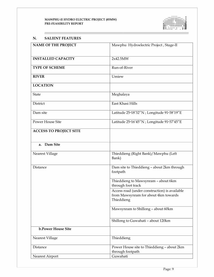
N. SALIENT FEATURES
NAME OF THE PROJECT
Mawphu Hydroelectric Project , Stage-II
INSTALLED CAPACITY
2x42.5MW
TYPE OF SCHEME
Run-of-River
RIVER
Umiew
LOCATION
State
Meghalaya
District
East Khasi Hills
Dam site
Latitude 25o18’32”N ; Longitude 91o38’19”E
Power House Site
Latitude 25o16’45”N ; Longitude 91o37’45”E
ACCESS TO PROJECT SITE
a. Dam Site
Nearest Village
Thieddieng (Right Bank)/Mawphu (Left Bank)
Distance
Dam site to Thieddieng – about 2km through footpath
Thieddieng to Mawsynram – about 6km through foot track
Access road (under construction) is available from Mawsynram for about 4km towards Thieddieng
Mawsynram to Shillong – about 60km
Shillong to Guwahati – about 120km
b.Power House Site
Nearest Village
Thieddieng
Distance
Power House site to Thieddieng – about 2km through footpath
Nearest Airport Guwahati
MAWPHU-II HYDRO ELECTRIC PROJECT (85MW)
MAWPHU-II HYDRO ELECTRIC PROJECT (85MW)
PRE-FEASIBILITY REPORT
Page: 10
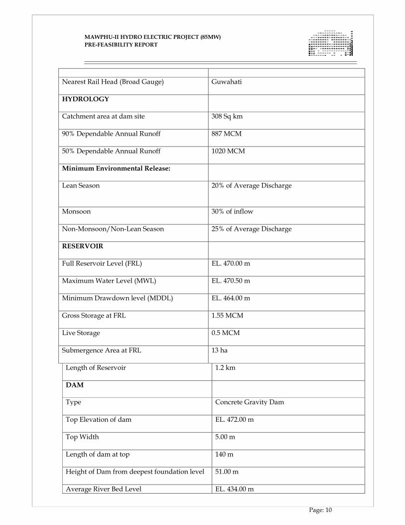
Nearest Rail Head (Broad Gauge)
Guwahati
HYDROLOGY
Catchment area at dam site
308 Sq km
90% Dependable Annual Runoff
887 MCM
50% Dependable Annual Runoff
1020 MCM
Minimum Environmental Release:
Lean Season
20% of Average Discharge
Monsoon
30% of inflow
Non-Monsoon/Non-Lean Season
25% of Average Discharge
RESERVOIR
Full Reservoir Level (FRL)
EL. 470.00 m
Maximum Water Level (MWL)
EL. 470.50 m
Minimum Drawdown level (MDDL)
EL. 464.00 m
Gross Storage at FRL
1.55 MCM
Live Storage
0.5 MCM
Submergence Area at FRL
13 ha
Length of Reservoir
1.2 km
DAM
Type
Concrete Gravity Dam
Top Elevation of dam
EL. 472.00 m
Top Width
5.00 m
Length of dam at top
140 m
Height of Dam from deepest foundation level
51.00 m
Average River Bed Level EL. 434.00 m
MAWPHU-II HYDRO ELECTRIC PROJECT (85MW)
MAWPHU-II HYDRO ELECTRIC PROJECT (85MW)
PRE-FEASIBILITY REPORT
Page: 11
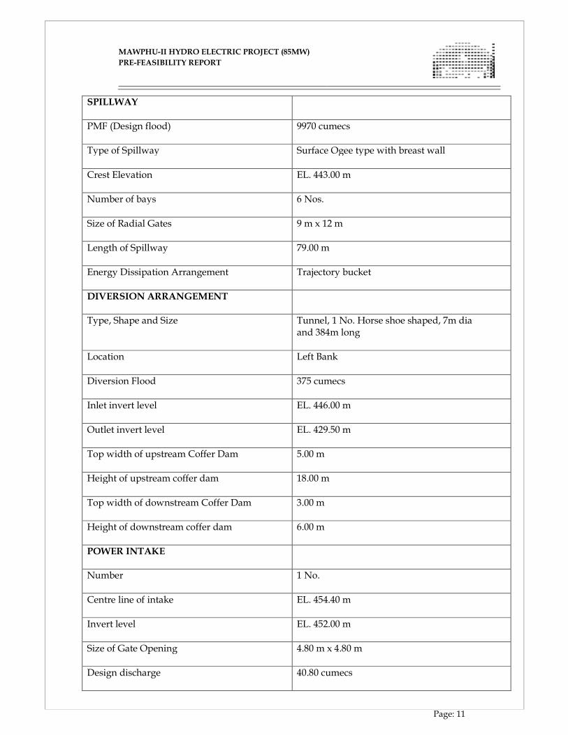
SPILLWAY
PMF (Design flood)
9970 cumecs
Type of Spillway
Surface Ogee type with breast wall
Crest Elevation
EL. 443.00 m
Number of bays
6 Nos.
Size of Radial Gates
9 m x 12 m
Length of Spillway
79.00 m
Energy Dissipation Arrangement
Trajectory bucket
DIVERSION ARRANGEMENT
Type, Shape and Size
Tunnel, 1 No. Horse shoe shaped, 7m dia and 384m long
Location
Left Bank
Diversion Flood
375 cumecs
Inlet invert level
EL. 446.00 m
Outlet invert level
EL. 429.50 m
Top width of upstream Coffer Dam
5.00 m
Height of upstream coffer dam
18.00 m
Top width of downstream Coffer Dam
3.00 m
Height of downstream coffer dam
6.00 m
POWER INTAKE
Number
1 No.
Centre line of intake
EL. 454.40 m
Invert level
EL. 452.00 m
Size of Gate Opening
4.80 m x 4.80 m
Design discharge
40.80 cumecs
MAWPHU-II HYDRO ELECTRIC PROJECT (85MW)
MAWPHU-II HYDRO ELECTRIC PROJECT (85MW)
PRE-FEASIBILITY REPORT
Page: 12
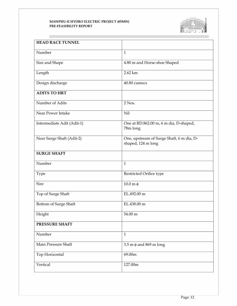
HEAD RACE TUNNEL
Number
1
Size and Shape
4.80 m and Horse-shoe Shaped
Length
2.62 km
Design discharge
40.80 cumecs
ADITS TO HRT
Number of Adits
2 Nos.
Near Power Intake
Nil
Intermediate Adit (Adit-1)
One at RD.862.00 m, 6 m dia, D-shaped, 78m long
Near Surge Shaft (Adit-2) One, upstream of Surge Shaft, 6 m dia, D-shaped, 124 m long
SURGE SHAFT
Number
1
Type
Restricted Orifice type
Size
10.0 m φ
Top of Surge Shaft
EL.492.00 m
Bottom of Surge Shaft
EL.438.00 m
Height
54.00 m
PRESSURE SHAFT
Number
1
Main Pressure Shaft
3.5 m φ and 869 m long
Top Horizontal
69.00m
Vertical
127.00m
MAWPHU-II HYDRO ELECTRIC PROJECT (85MW)
MAWPHU-II HYDRO ELECTRIC PROJECT (85MW)
PRE-FEASIBILITY REPORT
Page: 13
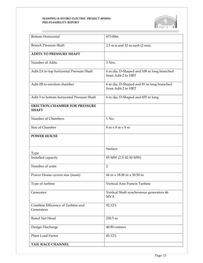
Bottom Horizontal
673.00m
Branch Pressure Shaft
2.5 m φ and 32 m each (2 nos)
ADITS TO PRESSURE SHAFT
Number of Adits
3 Nos.
Adit-2A to top horizontal Pressure Shaft
6 m dia, D-Shaped and 108 m long branched from Adit-2 to HRT
Adit-2B to erection chamber
6 m dia, D-Shaped and 81 m long branched from Adit-2 to HRT
Adit-3 to bottom horizontal Pressure Shaft
6 m dia, D-Shaped and 455 m long
ERECTION CHAMBER FOR PRESSURE
SHAFT
Number of Chambers
1 No.
Size of Chamber
8 m x 8 m x 8 m
POWER HOUSE
Type
Surface
Installed capacity
85 MW (2 X 42.50 MW)
Number of units
2
Power House cavern size (main)
66 m x 18.00 m x 30.50 m
Type of turbine
Vertical Axis Francis Turbine
Generator
Vertical Shaft synchronous generators 46 MVA
Combine Efficiency of Turbine and Generators
92.12%
Rated Net Head
230.5 m
Design Discharge
40.80 cumecs
Plant Load Factor
45.12%
TAIL RACE CHANNEL
MAWPHU-II HYDRO ELECTRIC PROJECT (85MW)
MAWPHU-II HYDRO ELECTRIC PROJECT (85MW)
PRE-FEASIBILITY REPORT
Page: 14
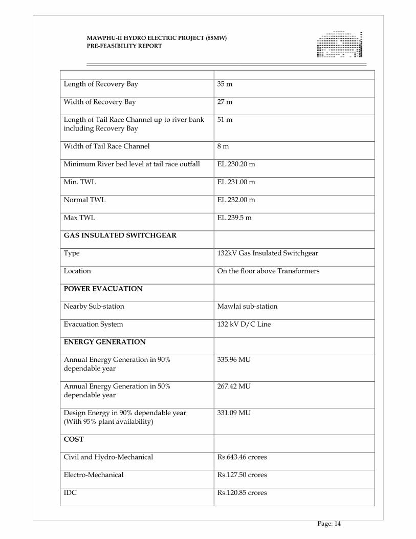
Length of Recovery Bay
35 m
Width of Recovery Bay
27 m
Length of Tail Race Channel up to river bank including Recovery Bay
51 m
Width of Tail Race Channel
8 m
Minimum River bed level at tail race outfall
EL.230.20 m
Min. TWL
EL.231.00 m
Normal TWL
EL.232.00 m
Max TWL
EL.239.5 m
GAS INSULATED SWITCHGEAR
Type
132kV Gas Insulated Switchgear
Location
On the floor above Transformers
POWER EVACUATION
Nearby Sub-station
Mawlai sub-station
Evacuation System
132 kV D/C Line
ENERGY GENERATION
Annual Energy Generation in 90% dependable year
335.96 MU
Annual Energy Generation in 50% dependable year
267.42 MU
Design Energy in 90% dependable year (With 95% plant availability)
331.09 MU
COST
Civil and Hydro-Mechanical
Rs.643.46 crores
Electro-Mechanical
Rs.127.50 crores
IDC
Rs.120.85 crores
MAWPHU-II HYDRO ELECTRIC PROJECT (85MW)
MAWPHU-II HYDRO ELECTRIC PROJECT (85MW)
PRE-FEASIBILITY REPORT
Page: 15
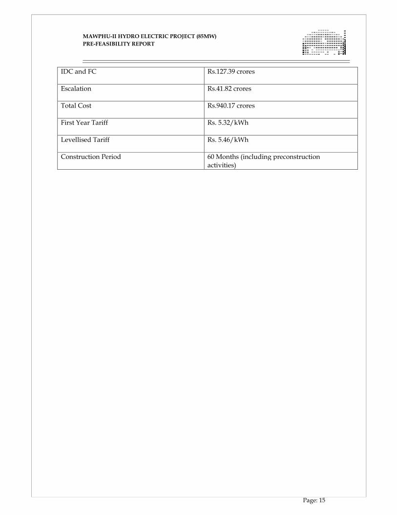
IDC and FC
Rs.127.39 crores
Escalation
Rs.41.82 crores
Total Cost
Rs.940.17 crores
First Year Tariff
Rs. 5.32/kWh
Levellised Tariff
Rs. 5.46/kWh
Construction Period
60 Months (including preconstruction activities)

CHAPTER - II
BACKGROUND INFORMATION

MAWPHU-II HYDRO ELECTRIC PROJECT (85MW)
MAWPHU-II HYDRO ELECTRIC PROJECT (85MW)
PRE-FEASIBILITY REPORT
Page: 16
CHAPTER II
BACKGROUND INFORMATION
2.1 GENERAL
The North-Eastern Region of India has vast potential for hydro power development. The
potential of two major river systems, namely the Brahmaputra and the Barak remains
largely untapped as on date. This may be the prime reason for poor electricity generation
in the region with cascading effect on industrialization and standard of living of people.
In recent times, major emphasis has been given to develop different power projects like
hydro, thermal, solar, wind etc. in the region. The gas based power projects have not been
able to fulfill the promises for uninterrupted less polluting electricity due to severe gap
between estimated gas to be developed and actual available at site. Most of the projects
based on alternative sources like wind, solar are in planning stage without much
presence on ground.
2.2 POWER SCENARIO IN NORTH EASTERN REGION
The North Eastern Region comprises of the States of Arunachal Pradesh, Assam,
Manipur, Meghalaya, Mizoram, Nagaland, Sikkim and Tripura. The whole region is
endowed with various perennial rivers and water bodies, hence, the region is blessed
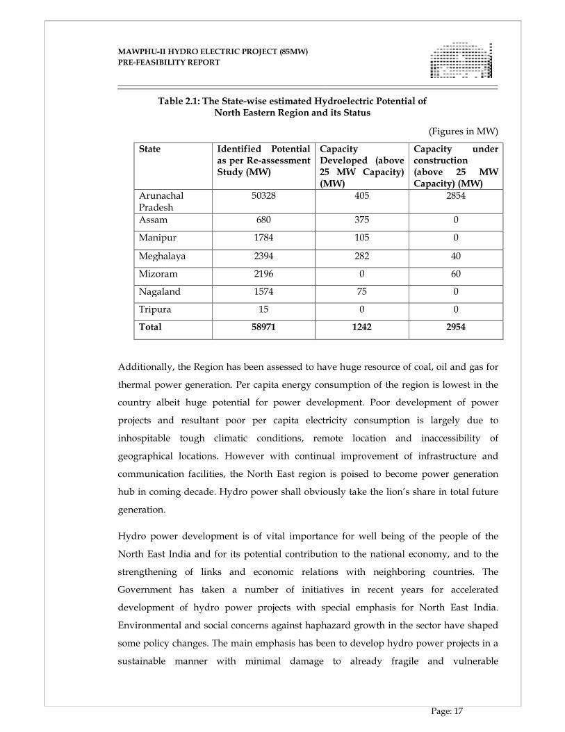
with huge hydro electricity potential. As per Re-assessment Studies carried out by CEA,
hydro potential of the North Eastern Region in terms of installed capacity has been
estimated as 58971 MW (58356 MW above25 MW capacity) i.e. almost 40% of the
country's total hydro potential. Out of the above, 1242 MW (above 25 MW capacity) have
been harnessed, while projects amounting to 2954 MW are under construction as on May
2015.
The State-wise estimated hydroelectric potential of North Eastern Region and its status of
development is given below as on May 2015 (Source: CEA website):
MAWPHU-II HYDRO ELECTRIC PROJECT (85MW)
MAWPHU-II HYDRO ELECTRIC PROJECT (85MW)
PRE-FEASIBILITY REPORT
Page: 17
Table 2.1: The State-wise estimated Hydroelectric Potential of North Eastern Region and its Status
Additionally, the Region has been assessed to have huge resource of coal, oil and gas for
thermal power generation. Per capita energy consumption of the region is lowest in the
country albeit huge potential for power development. Poor development of power
projects and resultant poor per capita electricity consumption is largely due to
inhospitable tough climatic conditions, remote location and inaccessibility of
geographical locations. However with continual improvement of infrastructure and
communication facilities, the North East region is poised to become power generation
hub in coming decade. Hydro power shall obviously take the lion’s share in total future
generation.
Hydro power development is of vital importance for well being of the people of the
North East India and for its potential contribution to the national economy, and to the
strengthening of links and economic relations with neighboring countries. The
Government has taken a number of initiatives in recent years for accelerated
development of hydro power projects with special emphasis for North East India.
Environmental and social concerns against haphazard growth in the sector have shaped
some policy changes. The main emphasis has been to develop hydro power projects in a
sustainable manner with minimal damage to already fragile and vulnerable
(Figures in MW)
State Identified Potential as per Re-assessment Study (MW)
Capacity Developed (above 25 MW Capacity) (MW)
Capacity under construction (above 25 MW Capacity) (MW)
Arunachal Pradesh
50328 405 2854
Assam 680 375 0
Manipur 1784 105 0
Meghalaya 2394 282 40
Mizoram 2196 0 60
Nagaland 1574 75 0
Tripura 15 0 0
Total 58971 1242 2954
MAWPHU-II HYDRO ELECTRIC PROJECT (85MW)
MAWPHU-II HYDRO ELECTRIC PROJECT (85MW)
PRE-FEASIBILITY REPORT
Page: 18
environmentof the region. The main emphasis has been on integrated basin development
with detailed study on cumulative impact of environment.
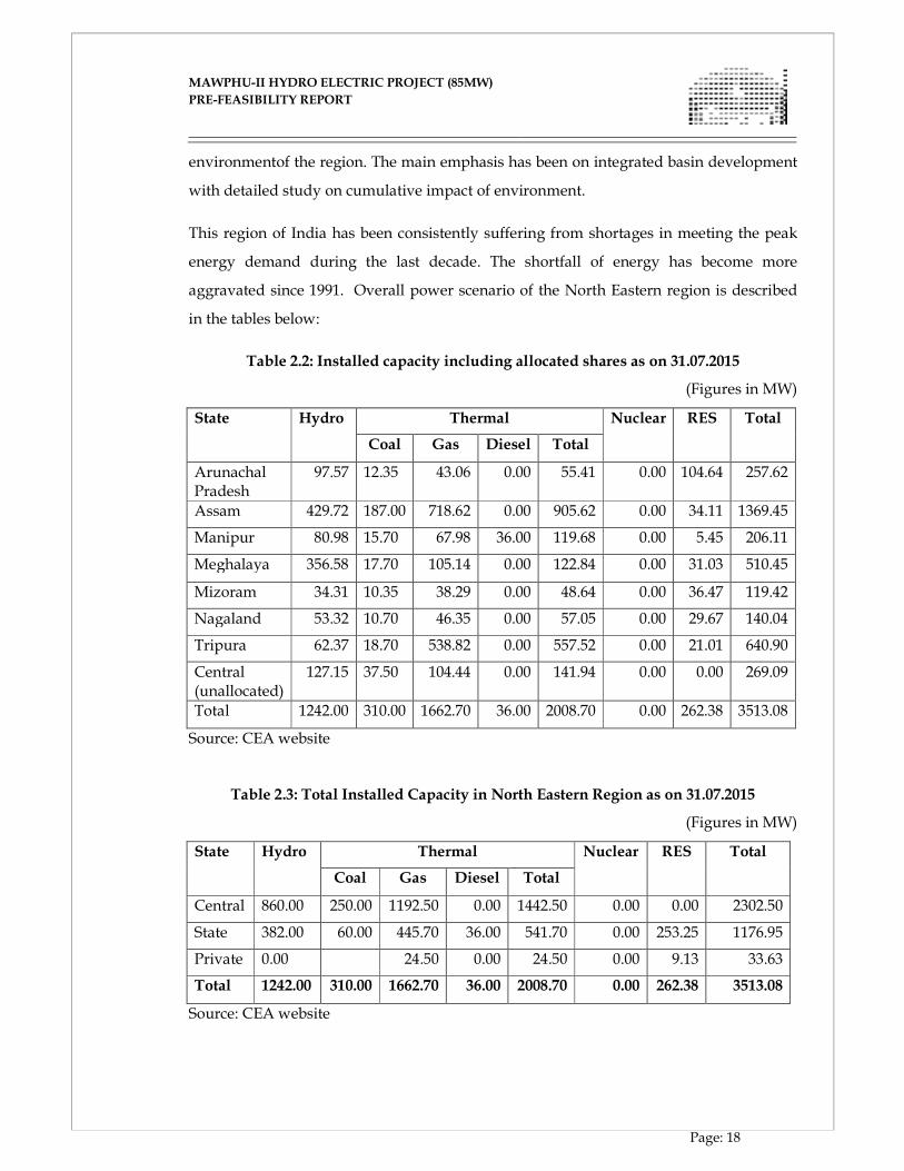
This region of India has been consistently suffering from shortages in meeting the peak
energy demand during the last decade. The shortfall of energy has become more
aggravated since 1991. Overall power scenario of the North Eastern region is described
in the tables below:
Table 2.2: Installed capacity including allocated shares as on 31.07.2015
(Figures in MW)
State Hydro Thermal Nuclear RES Total
Coal Gas Diesel Total
Arunachal Pradesh
97.57 12.35 43.06 0.00 55.41 0.00 104.64 257.62
Assam 429.72 187.00 718.62 0.00 905.62 0.00 34.11 1369.45
Manipur 80.98 15.70 67.98 36.00 119.68 0.00 5.45 206.11
Meghalaya 356.58 17.70 105.14 0.00 122.84 0.00 31.03 510.45
Mizoram 34.31 10.35 38.29 0.00 48.64 0.00 36.47 119.42
Nagaland 53.32 10.70 46.35 0.00 57.05 0.00 29.67 140.04
Tripura 62.37 18.70 538.82 0.00 557.52 0.00 21.01 640.90
Central (unallocated)
127.15 37.50 104.44 0.00 141.94 0.00 0.00 269.09
Total 1242.00 310.00 1662.70 36.00 2008.70 0.00 262.38 3513.08
Source: CEA website
Table 2.3: Total Installed Capacity in North Eastern Region as on 31.07.2015
(Figures in MW)
State Hydro Thermal Nuclear RES Total
Coal Gas Diesel Total
Central 860.00 250.00 1192.50 0.00 1442.50 0.00 0.00 2302.50
State 382.00 60.00 445.70 36.00 541.70 0.00 253.25 1176.95
Private 0.00 24.50 0.00 24.50 0.00 9.13 33.63
Total 1242.00 310.00 1662.70 36.00 2008.70 0.00 262.38 3513.08
Source: CEA website
MAWPHU-II HYDRO ELECTRIC PROJECT (85MW)
MAWPHU-II HYDRO ELECTRIC PROJECT (85MW)
PRE-FEASIBILITY REPORT
Page: 19
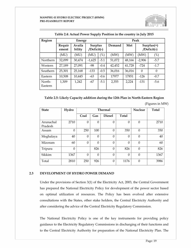
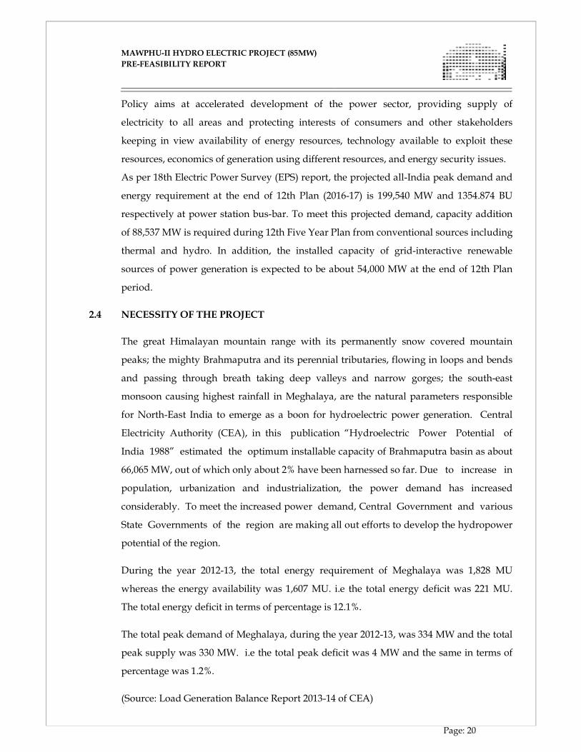
Table 2.4: Actual Power Supply Position in the country in July 2015
Region Energy Peak
Requirement
Availability
Surplus /Deficit(-)
Demand Met Surplus(+) /Deficit(-)
(MU) (MU) (MU) (%) (MW) (MW) (MW) (%)
Northern 32,099 30,474 -1,625 -5.1 51,072 48,166 -2,906 -5.7
Western 27,189 27,091 -98 -0.4 42,452 41,728 -724 -1.7
Southern 25,301 25,168 -133 -0.5 36,016 36,016 0 0
Eastern 10,508 10,445 -63 -0.6 17977 17851 -126 -0.7
North-Eastern
1,309 1,242 -67 -5.1 2,355 2,224 -131 -5.6
Table 2.5: Likely Capacity addition during the 12th Plan in North-Eastern Region
(Figures in MW)
State Hydro Thermal Nuclear Total
Coal Gas Diesel Total
Arunachal Pradesh
2710 0 0 0 0 0 2710
Assam 0 250 100 0 350 0 350
Meghalaya 40 0 0 0 0 0 40
Mizoram 60 0 0 0 0 0 60
Tripura 0 826 0 826 0 826
Sikkim 1367 0 0 0 0 0 1367
Total 2810 250 926 0 1176 0 3986
2.3 DEVELOPMENT OF HYDRO POWER DEMAND
Under the provisions of Section 3(1) of the Electricity Act, 2003, the Central Government
has prepared the National Electricity Policy for development of the power sector based
on optimal utilization of resources. The Policy has been evolved after extensive
consultations with the States, other stake holders, the Central Electricity Authority and
after considering the advice of the Central Electricity Regulatory Commission.
The National Electricity Policy is one of the key instruments for providing policy
guidance to the Electricity Regulatory Commissions in discharging of their functions and
to the Central Electricity Authority for preparation of the National Electricity Plan. The
MAWPHU-II HYDRO ELECTRIC PROJECT (85MW)
MAWPHU-II HYDRO ELECTRIC PROJECT (85MW)
PRE-FEASIBILITY REPORT
Page: 20
Policy aims at accelerated development of the power sector, providing supply of
electricity to all areas and protecting interests of consumers and other stakeholders
keeping in view availability of energy resources, technology available to exploit these
resources, economics of generation using different resources, and energy security issues.
As per 18th Electric Power Survey (EPS) report, the projected all-India peak demand and
energy requirement at the end of 12th Plan (2016-17) is 199,540 MW and 1354.874 BU
respectively at power station bus-bar. To meet this projected demand, capacity addition
of 88,537 MW is required during 12th Five Year Plan from conventional sources including
thermal and hydro. In addition, the installed capacity of grid-interactive renewable
sources of power generation is expected to be about 54,000 MW at the end of 12th Plan
period.
2.4 NECESSITY OF THE PROJECT
The great Himalayan mountain range with its permanently snow covered mountain
peaks; the mighty Brahmaputra and its perennial tributaries, flowing in loops and bends
and passing through breath taking deep valleys and narrow gorges; the south-east
monsoon causing highest rainfall in Meghalaya, are the natural parameters responsible
for North-East India to emerge as a boon for hydroelectric power generation. Central
Electricity Authority (CEA), in this publication “Hydroelectric Power Potential of
India 1988” estimated the optimum installable capacity of Brahmaputra basin as about
66,065 MW, out of which only about 2% have been harnessed so far. Due to increase in
population, urbanization and industrialization, the power demand has increased
considerably. To meet the increased power demand, Central Government and various
State Governments of the region are making all out efforts to develop the hydropower
potential of the region.
During the year 2012-13, the total energy requirement of Meghalaya was 1,828 MU
whereas the energy availability was 1,607 MU. i.e the total energy deficit was 221 MU.
The total energy deficit in terms of percentage is 12.1%.
The total peak demand of Meghalaya, during the year 2012-13, was 334 MW and the total
peak supply was 330 MW. i.e the total peak deficit was 4 MW and the same in terms of
percentage was 1.2%.
(Source: Load Generation Balance Report 2013-14 of CEA)

MAWPHU-II HYDRO ELECTRIC PROJECT (85MW)
MAWPHU-II HYDRO ELECTRIC PROJECT (85MW)
PRE-FEASIBILITY REPORT
Page: 21
Therefore, in order to meet the increasing peak energy demand of the state as well as the
region, it is an essential requirement to utilize the hydro power potential of Meghalaya to
boost the industrial as well as overall growth in the state.
Though Mawphu HEP, Stage – II, has been planned as a Run-of-the River scheme, it
would however be possible to derive peaking benefits with the help of diurnal
storage being provided.
CHAPTER - III
PROJECT AREA
MAWPHU-II HYDRO ELECTRIC PROJECT (85MW)
MAWPHU-II HYDRO ELECTRIC PROJECT (85MW)
PRE-FEASIBILITY REPORT
Page: 22
CHAPTER - III
THE PROJECT AREA
3.1 GENERAL
Mawphu Hydro Electric Project, Stage - II is proposed as a run-of-river scheme on
the river Umiew in East Khasi Hills District of Meghalaya. The proposed dam site
is located at about 3.17km downstream of Umduna HEP (90 MW) Power House
location and the Power House site is located at about 2km downstream of
Thieddieng village on the right bank of the river. The proposed dam site is located at
latitude 25°18’32”N and longitude 91°38’19”E.
The Umiew River (known as Umlam in initial reaches) originates as a small stream
between latitudes 25° 19’ N and 25° 33’ N and longitudes 91° 35‘ 30” E and 91° 56’ E at an
elevation of about 1940 m in East Khasi hills of Meghalaya. Initially the river flows in
southern direction for about 4 km with a slope of about 1 in 30. For the next 6 km, it flows
in south-eastern direction with relatively flat gradient of 1 in 225. Few small streams and
nallas join in this stretch enriching its discharge. It then turns westwards and continues
its path for further 12 km before it turns in south west direction. The 7 km journey in
south west direction upto Mawphlang is quite steep with a gradient of about 1 in
12. At Mawphlang the river is barricaded by a dam to form a reservoir for a scheme
project known as Greater Shillong Water Supply Scheme (GSWSS). Fulfilling the drinking
water need of Shillong is the primary objective of the scheme.
Main tributaries of Umiew up to GSWSS are Umjilling, Umtongsieum and Wah Umsaw.
After crossing this scheme project, river extends its journey for about 13 km in a gradient
of about 1 in 175. Nallas like Umjaut, Umduna join in its right bank and Umlong joins in
its left bank. The discharges of these nallas increase the potential of the river to develop
the proposed Mawphu HEP, Stage - I (90 MW) Hydro Power Project. Mawphu HEP,
Stage - II (85 MW) Project lies further 13 km downstream of Mawphu HEP, Stage - I
Project with additional contributions from Umjngut & Umkynrem nallas, which join in
the right bank. The total length of the river up to the project site is 54.54 km. The river
reach in between two projects comprises of many loops and bends which gives a
panoramic view to the observers. Further the river flows towards the south below the
confluence along the southern slopes of Khasi Hills and enters Bangladesh beyond Shella
MAWPHU-II HYDRO ELECTRIC PROJECT (85MW)
MAWPHU-II HYDRO ELECTRIC PROJECT (85MW)
PRE-FEASIBILITY REPORT
Page: 23
in Indo-Bangladesh border and joins the River Surma. Finally the river joins
Brahmaputra and in turn flows to Bay of Bengal via Sundarbans Delta.
The basin is bounded by Mawsynram in west, Shillong in North and Cherrapunji in east
and in fact world’s highest annual rainfall occurs at Cherrapunji and Mawsynram. The
slopes of the basin are covered with dense rainforests of coniferous and deciduous
trees with a number of small tribal villages in between. The predominant land use
pattern in the catchment area is forest of the type “Tropical Moist Deciduous”. Very
small area is under agricultural use including wet rice cultivation in the intercept valleys.
3.2 PROJECT BACKGROUND
Under the 50000 MW hydro power initiatives, Pre-Feasibility Reports for the following
three projects on Umiew River Basin of Meghalaya were prepared by WAPCOS (Figure
3.1).
i. Umjaut HEP (69MW): FRL-1346m, TWL - 952m
ii. Umduna HEP (57MW): FRL-950m, TWL - 687m
iii. Mawphu HEP (120MW): FRL-684m, TWL - 210.5m
Figure 3.1: Umiew River Projects (WAPCOS)
MAWPHU-II HYDRO ELECTRIC PROJECT (85MW)
MAWPHU-II HYDRO ELECTRIC PROJECT (85MW)
PRE-FEASIBILITY REPORT
Page: 24
After receiving authorization from the Govt. of Meghalaya in May'2005, NEEPCO took
up detailed Survey & Investigation for preparation of DPR of Mawphu HEP (120MW).
However, as observed by GSI, NER, the dam site location as mentioned in the PFR was
found to be not suitable because of non availability of abutment and it was also advised
for an alternative location. At the same time, some of the project parameters as cited in its
PFR were found to have some discrepancy with respect to the relevant topo sheet as well
as the actual field values. Hence, NEEPCO went ahead for selection of alternate site. As a
consequence, the whole lay out underwent alteration. After carrying out overall study of
the basin, it was found that for the other projects also, the parameters were deviating
with respect to topo sheet.
Considering all the above factors and comments of CEA regarding the unviability of
Umjaut HEP (69MW), NEEPCO carried out an optimization study (Figure 3.2) of the
whole basin in the following location limits.
i. Umjaut HEP (50 MW) : FRL-1346m, TWL-1025m.
ii. Mawphu HEP (90 MW) : FRL-1018.6m, TWL-542.68 m.
(In place of Umduna HEP-57 MW)
iii. Mawphu HEP (Stage-II) - 85MW: FRL-540m, TWL-210m.
NEEPCO prepared the DPR for Mawphu HEP (90MW) and submitted to MOP/CEA in
Mar' 2007. But later on, Govt. of Meghalaya allotted this along with Umjaut HEP to a
private developer (M/s ETA Star Infrastructures Ltd.) and NEEPCO was given the
downstream Mawphu HEP (Stage-II).
In June 2012, NEEPCO invited bids from engineering consultants for detailed survey,
investigations and preparation of detailed project report of Mawphu HEP Stage-II
and awarded the work to M/s Energy Infratech Pvt. Ltd. (EIPL) in December 2012.
EIPL has studied the available PFR and found that there is very less free stretch of river
between the proposed FRL at EL 540.00 m and upstream project power house TWL at
542.68m. EIPL pointed out this issue as it is much less than that of 1 km required for
environmental considerations of MoEF.
MAWPHU-II HYDRO ELECTRIC PROJECT (85MW)
MAWPHU-II HYDRO ELECTRIC PROJECT (85MW)
PRE-FEASIBILITY REPORT
Page: 25
Figure 3.2: Umiew River Project 3.3 ALTERNATIVE STUDIES
3.3.1 ALTERNATIVE LOCATIONS OF DAM
The following aspects were considered in general for the selection of the dam site:
� Topographical features of the site
� Preliminary geological and geo-technical considerations
� Accommodation of spillway arrangement to pass the design flood
� Location of Energy Dissipation arrangement
� Availability of Construction Materials
� Location of proposed u/s and d/s projects
� Environmental Requirements
Various alternative locations were identified to select the most suitable location for dam.
As the river is flowing through number of sharp bends (Figure 3.3), the dam alternatives
were identified immediately downstream of such bends so that maximum straight reach
would remain downstream for energy dissipation point of view.
Following locations have been considered for Dam:

MAWPHU-II HYDRO ELECTRIC PROJECT (85MW)
MAWPHU-II HYDRO ELECTRIC PROJECT (85MW)
PRE-FEASIBILITY REPORT
Page: 26
A. Old PFR Location (about 1km downstream of proposed Power House
location of upstream project - Umduna HEP)
B. Alt-1 about 2km downstream of Umduna HEP Power House Location
C. Alt-2 about 2.5km downstream of Umduna HEP Power House Location
D. Alt-3 about 3.1km downstream of Umduna HEP Power House Location
E. Alt-3A about 70 m downstream of Alt-3
3.3.1.1 OLD PFR (2010) LOCATION
� This location is about 1.2 km downstream of upstream project power house location.
The upstream project TWL is EL 542.68 m and FRL of this project was at El 540.00
m. Considering the average slope of 1 in 22 m there will be a free stretch of river of
about 50-60 m between two projects. View of site is presented in following
photographs.
� The river is filled up with big boulders (average ~5 m dia). Width of river is about
100 m and more than 50 % bed is exposed with in-situ rock. The river starts flowing
in sharp bend after about 300-400 m downstream of the proposed dam location.
� Sound rock shall be available at shallow depth at both the abutments.
MAWPHU-II HYDRO ELECTRIC PROJECT (85MW)
MAWPHU-II HYDRO ELECTRIC PROJECT (85MW)
PRE-FEASIBILITY REPORT
Page: 27
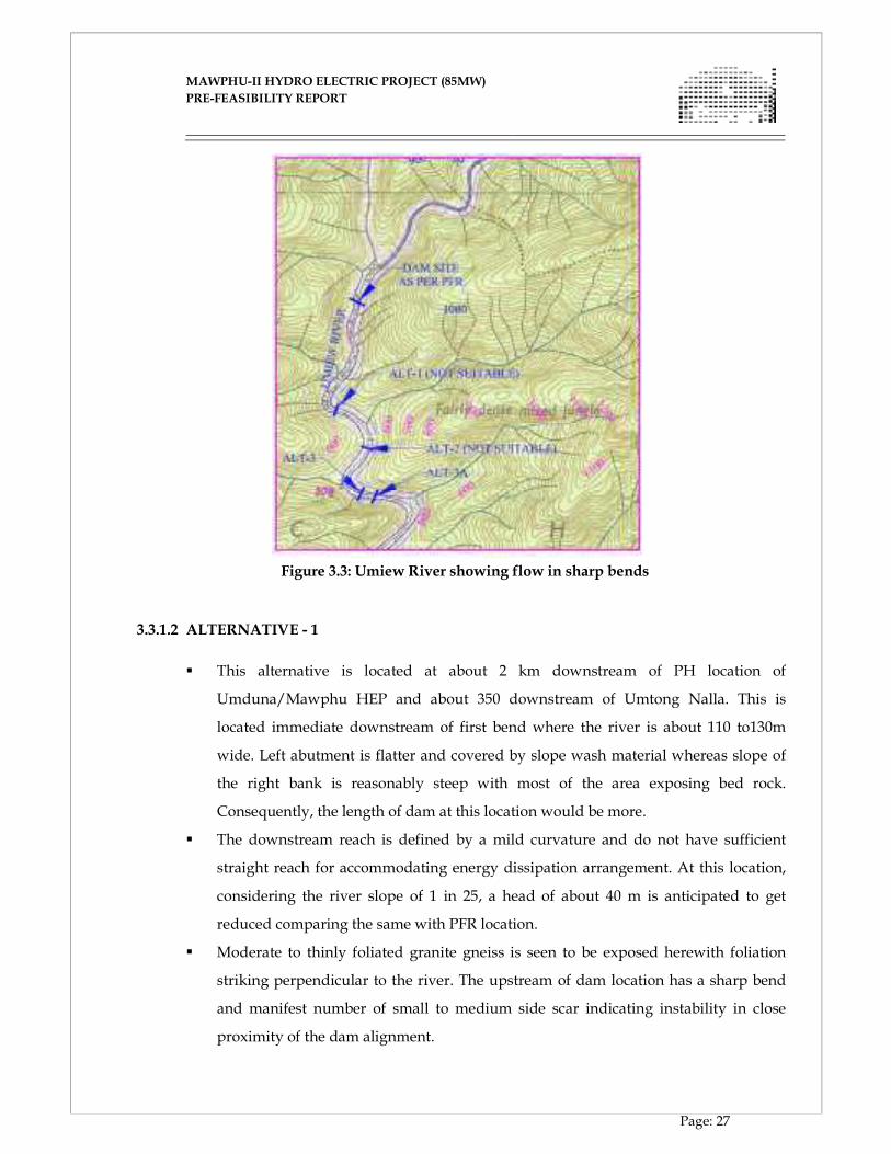
Figure 3.3: Umiew River showing flow in sharp bends
3.3.1.2 ALTERNATIVE - 1
� This alternative is located at about 2 km downstream of PH location of
Umduna/Mawphu HEP and about 350 downstream of Umtong Nalla. This is
located immediate downstream of first bend where the river is about 110 to130m
wide. Left abutment is flatter and covered by slope wash material whereas slope of
the right bank is reasonably steep with most of the area exposing bed rock.
Consequently, the length of dam at this location would be more.
� The downstream reach is defined by a mild curvature and do not have sufficient
straight reach for accommodating energy dissipation arrangement. At this location,
considering the river slope of 1 in 25, a head of about 40 m is anticipated to get
reduced comparing the same with PFR location.
� Moderate to thinly foliated granite gneiss is seen to be exposed herewith foliation
striking perpendicular to the river. The upstream of dam location has a sharp bend
and manifest number of small to medium side scar indicating instability in close
proximity of the dam alignment.
MAWPHU-II HYDRO ELECTRIC PROJECT (85MW)
MAWPHU-II HYDRO ELECTRIC PROJECT (85MW)
PRE-FEASIBILITY REPORT
Page: 28
3.3.1.3 ALTERNATIVE - 2
� This alternative is located at about 2.5 km downstream of PH location of
Umduna/ Mawphu HEP and about 200 m downstream of confluence of a small left
bank Nalla and immediate downstream of second bend.
� The river width at this location is about 100 to120m.
� Upstream location shows mild bend whereas downstream reach provides about 150
to 200 m straight course which may not be adequate for accommodating spillway
and energy dissipation arrangement.
� The left abutment falls in a ridge between two left bank nalla (Umtong Nalla and
Weisu Nalla) and HRT alignment will cross very deep Weisu Nalla in the
upstream reach. Locating an adit for HRT in this reach shall be difficult.
� At this stretch river slope seems to be 1 in 25 which would result a loss of head of
about 60 m when compared the same with PFR location.
� Both the banks at this location are subdued and are covered by deep slope wash
material of unknown thickness. However sporadic bed rock exposures constituted of
granite gneiss with mica rich bands exist.
3.3.1.4 ALTERNATIVE - 3
� This alternative is located at about 3.1 km downstream of PH location of
Umduna/ Mawphu HEP and about 250m downstream of confluence of right bank
Weisu Nalla.
� River is about 70-80 m wide. Right bank is consistently very steep and exposes
bedrock upto about 70m
� Initial slope of left Bank is steep upto about 30m above the present River bed level
after which the slope becomes gentle. About 300m long straight course exist in the
downstream reach, which can be considered acceptable for accommodating energy
dissipation arrangement.
� The HRT alignment is found to be more favorable as the same is not intersecting any
major nala.
� At this location considering the river slope of 1 in 25, head of about 80 m is
anticipated to get reduced comparing the same with PFR location.
� The discharge from the two perennial nalla Umtong & Weisu shall contribute
towards the overall discharge.
MAWPHU-II HYDRO ELECTRIC PROJECT (85MW)
MAWPHU-II HYDRO ELECTRIC PROJECT (85MW)
PRE-FEASIBILITY REPORT
Page: 29
A comparison has been presented in following table considering various aspects.
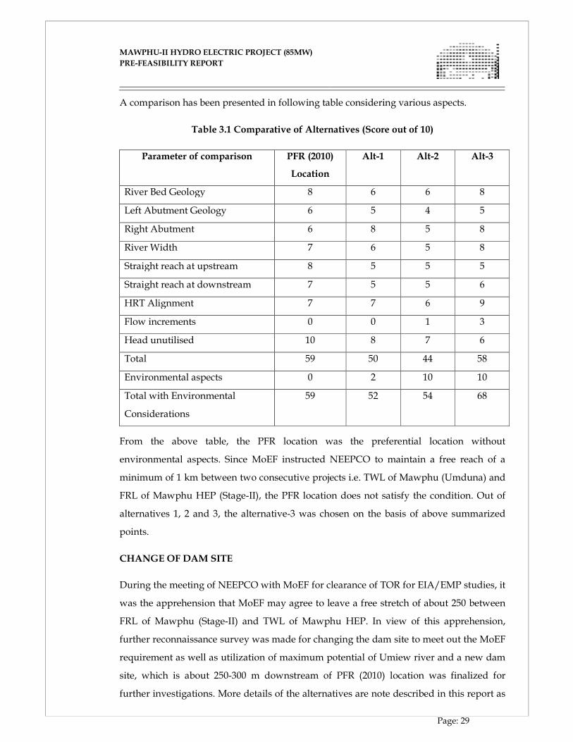
Table 3.1 Comparative of Alternatives (Score out of 10)
Parameter of comparison PFR (2010)
Location
Alt-1 Alt-2 Alt-3
River Bed Geology 8 6 6 8
Left Abutment Geology 6 5 4 5
Right Abutment 6 8 5 8
River Width 7 6 5 8
Straight reach at upstream 8 5 5 5
Straight reach at downstream 7 5 5 6
HRT Alignment 7 7 6 9
Flow increments 0 0 1 3
Head unutilised 10 8 7 6
Total 59 50 44 58
Environmental aspects 0 2 10 10
Total with Environmental
Considerations
59 52 54 68
From the above table, the PFR location was the preferential location without
environmental aspects. Since MoEF instructed NEEPCO to maintain a free reach of a
minimum of 1 km between two consecutive projects i.e. TWL of Mawphu (Umduna) and
FRL of Mawphu HEP (Stage-II), the PFR location does not satisfy the condition. Out of
alternatives 1, 2 and 3, the alternative-3 was chosen on the basis of above summarized
points.
CHANGE OF DAM SITE
During the meeting of NEEPCO with MoEF for clearance of TOR for EIA/EMP studies, it
was the apprehension that MoEF may agree to leave a free stretch of about 250 between
FRL of Mawphu (Stage-II) and TWL of Mawphu HEP. In view of this apprehension,
further reconnaissance survey was made for changing the dam site to meet out the MoEF
requirement as well as utilization of maximum potential of Umiew river and a new dam
site, which is about 250-300 m downstream of PFR (2010) location was finalized for
further investigations. More details of the alternatives are note described in this report as
MAWPHU-II HYDRO ELECTRIC PROJECT (85MW)
MAWPHU-II HYDRO ELECTRIC PROJECT (85MW)
PRE-FEASIBILITY REPORT
Page: 30
it was cancelled after receipt of written instructions of MoEF to maintain a minimum of 1
km free stretch between FRL of Mawphu (Stage-II) and TWL of Mawphu HEP. Therefore
further investigations were made on the earlier chosen location as Alternative-3.
3.3.1.5 ALTERNATIVE - 3A
� During the sub-surface investigations at dam alternative-3 DH-07, drilled at axis Alt-
3 encountered deep overburden down to 30.5m on the left bank of dam axis. Such
depressed bed rock profile indicates possible scouring/erosion of bed rock close to
concave side of the curvature along the river beyond the rock ledge.
� In view of the above and to find a suitable location, 70m downstream of Alternate-3,
a drill hole DH-09 was drilled on the left bank. The drill hole revealed the availability
of bed rock at a shallow depth and accordingly this alignment was favored.
� In view of these observations, Alternative-3a, located 70m downstream of Alternate-
3 and 340m downstream of Weisu Nalla was finalized for taking up further detailed
investigation.
MINOR ADJUSTMENT IN THE DAM AXIS ALTERNATIVE-3A
Initially during the preparation of PFR (Jan 2014), the design flood was estimated as 6000
cumecs and accordingly spillway bays were arranged in the dam layout plan. During the
clearance of hydrological studies from CWC, CWC recommended their suggestions and
design flood (PMF) was increased to 9970 cumecs.
In order to pass the design flood through spillway with 10% gate inoperative, two more
bays were required in the earlier spillway arrangement. Therefore, to accommodate
additional number of spillway bays, the dam axis proposed in the new PFR was rotated
slightly by about 30 in the clockwise direction through centre of river to avoid hitting of
water jet on the left abutment.
3.4 UPDATED PFR WITH REVISED INSTALLED CAPACITY OF 85MW
Environmental Clearance for pre-construction activities along with approved TOR was
accorded by MoEF&CC in May 2014. This clearance was obtained with project installed
capacity of 75MW and other associated parameters. EIA/EMP studies have been carried
out and completed based on above stated TOR. In the meantime, installed capacity of the

MAWPHU-II HYDRO ELECTRIC PROJECT (85MW)
MAWPHU-II HYDRO ELECTRIC PROJECT (85MW)
PRE-FEASIBILITY REPORT
Page: 31
project has undergone upward revision to 85MW as per recommendation of CEA vide
letter No. 20/14/2016-HPA-II/381 Dated 16.3.2016 (copy enclosed as Annexure 3.1).
Project parameters have remained unaltered with the above change in installed capacity
barring changes in Power House dimensions, Design Energy & Turbine-Generators.
Instant PFR has been prepared based on revised installed capacity of 85MW.
3.5 BASIN CHARACTERISTICS
Mawphu Hydro Electric Power Project (Stage-II) is planned in East Khasi Hills District in
the state of Meghalaya on the River Umiew, a tributary of the River Surma, which itself is
one of the major left bank tributaries of Brahmaputra. Mawphu Hydro Electric Project
(Stage-II) envisages the construction of a concrete gravity dam of about 51 m height (from
deepest bed level) across river Umiew to utilize a net head of about 232 m for hydro
power generation. The proposed dam is located near Mawphu village, about 8 km away
from Mawsynram and 2 km away from Thieddieng village. The catchment area up to the
dam site is 308 sq. km and the entire catchment is rain – fed. The Umiew River (known as
Umlam in initial reaches) originates as a small stream between latitudes 25º 19’ N and 25º
33’ N and longitudes 91º 35‘30” E and 91º 56’E at an elevation of about 1940 m in East
Khasi hills of Meghalaya. Initially the River flows in southern direction for about 4 km
with a slope of about 1 in 30. For the next 6 km, it flows in south-eastern direction with
relatively flat gradient of 1 in 225. Few small streams and nallas join in this stretch
enriching its discharge. It then turns westwards and continues its path for further 12 km
before it turns in south west direction. The 7 km journey in south west direction up to
Mawphlang is quite steep with a gradient of about 1 in 12. At Mawphlang the river is
barricaded by a dam to form a reservoir for a scheme project known as Greater Shillong
Water Supply Scheme (GSWSS). Fulfilling the drinking water need of Shillong is the
primary objective of the scheme.
Main tributaries of Umiew up to GSWSS are Umjilling, Umtongsieum and Wah Umsaw.
After crossing this scheme project, river extends its journey for about 13 km in a gradient
of about 1 in 175. Nallas like Umjaut, Umduna join in its right bank and Umlong joins in
its left bank.
The discharges of these nallas increase the potential of the river to develop the proposed
Mawphu Stage I (90 MW) Hydro Power Project. Mawphu Stage II (85 MW) Project lies
further 13 km downstream of Mawphu Stage I Project with additional contributions from
MAWPHU-II HYDRO ELECTRIC PROJECT (85MW)
MAWPHU-II HYDRO ELECTRIC PROJECT (85MW)
PRE-FEASIBILITY REPORT
Page: 32
Umjngut & Umkynrem nallas, which join in the right bank. The total length of the river
up to the project site is 54.54 km.
The basin is bounded by Mawsynram in west, Shillong in North and Cherrapunji in east
and in fact world’s highest annual rainfall occurs at Cherrapunji and Mawsynram. The
slopes of the basin are covered with dense rainforests of coniferous and deciduous trees
with a number of small tribal villages in between. The predominant land use pattern in
the catchment area is forest of the type “Tropical Moist Deciduous”. Very small area is
under agricultural use including wet rice cultivation in the intercept valleys.
3.6 CLIMATE
The proposed dam is near to the village Mawphu (L/B) and the power house is near to
Thieddieng village (R/B) in East Khasi Hills District of Meghalaya. The climate of the
sub-basin characterized by torrential rains caused by South West monsoon and 60% to
70% rainfall occurs between June to September. The river flows in deep channel and
swells into torrents during the rainy season while during the remaining months it has not
much significant flow. The river has floods during June to October with peaks mostly
occurring in July to September.
3.7 SOCIO-ECONOMIC PROFILE
Meghalaya gained status of Union State on 21st Jan. 1972. The State is situated between
the Brahmaputra valley on the North and Bangladesh on the south. Meghalaya has been
bestowed with abundant rainfall, plenty of sun shine, forest wealth, high plateaus and
waterfalls with river system meandering out to Bangladesh. The undulating topography
predominates the state with the highest peak rising to El 1965 m. The rainfall is highly
variable. East Khasi Hills is one of the seven districts of Meghalaya covering an area of
2748 sq. km. Shillong is the district headquarters of East Khasi Hills which is also the
capital of Meghalaya. Shillong is well connected by road with other places in the district
as well as with the rest of the Meghalaya and Assam. Shillong is connected by road with
all major north eastern states. Two major National Highways pass through East Khasi
Hills District -National Highway 40 connects Shillong to Jorabat, Assam in the north and
extends southwards to Dauki, at Bangladesh border and National Highway 44 connects
Shillong to states of Tripura and Mizoram. As per 2011 census (provisional), the total
population of the district is about 824,059 with male population of 410,360 and female
population of 413,699 (a sex ratio of about 1008 females per thousand males), with rural
MAWPHU-II HYDRO ELECTRIC PROJECT (85MW)
MAWPHU-II HYDRO ELECTRIC PROJECT (85MW)
PRE-FEASIBILITY REPORT
Page: 33
population of 458,010 and urban population of 366,049. The main occupation of the
population in the district is agriculture. In census enumeration, data regarding child
under 0-6 age were also collected for all districts including East Khasi Hills. There were
total 139,055 children under age of 0-6 against 115,169 of 2001 census. Of total 139,055
male and female were 70,805 and 68,250 respectively. Child Sex Ratio as per census 2011
was 964 compared to 972 of census 2001. In 2011, Children under 0-6 formed 16.84
percent of East Khasi Hills District compared to 17.43 percent of 2001. There was net
change of -0.59 percent in this compared to previous census of India In census
enumeration, data regarding child under 0-6 age were also collected for all districts
including East Khasi Hills. There were total 139,055 children under age of 0-6 against
115,169 of 2001 census. Of total 139,055 male and female were 70,805 and 68,250
respectively. Child Sex Ratio as per census 2011 was 964 compared to 972 of census 2001.
In 2011, Children under 0-6 formed 16.84 percent of East Khasi Hills District compared to
17.43 percent of 2001. Therewas net change of -0.59 percent in this compared to previous
census of India Description 2011.
THE PEOPLE
The Khasis occupying the northern lowlands and foothills are generally called Bhois.
Those who live in the southern tracts are termed Wars. Again among the Wars, those
living in the Khasi Hills are called War-Khasis and those in the Jaintia Hills, War-Pnars or
War-Jaintias. In the Jaintia Hills we have Khyrwangs, Labangs, Nangphylluts, Nangtungs
in the north-eastern part and in the east. In the Khasi Hills the Lyngngams live in the
north-western part. But all of them claim to have descended from the 'Ki Hynniew Trep'
and are now known by the generic name of Khasi-Pnars or simply Khasis. They have the
same traditions, customs and usage with a little variation owing to geographical
divisions.
DRESS
The traditional Khasi male dress is "Jymphong" or a longish sleeveless coat without collar,
fastened by thongs in front. Now, the Khasis have adopted the western dress. On
ceremonial occasions, they appear in “Jymphong" and dhoti with an ornamental waist-
band. The Khasi traditional female dress is rather elaborate with several pieces of cloth,
giving the body a cylindrical shape. On ceremonial occasions, they wear a crown of silver
or gold on the head. A spike or peak is fixed to the back of the crown, corresponding to
the feathers worn by the menfolk.

MAWPHU-II HYDRO ELECTRIC PROJECT (85MW)
MAWPHU-II HYDRO ELECTRIC PROJECT (85MW)
PRE-FEASIBILITY REPORT
Page: 34
FOOD & DRINKS
The staple food of Khasis is rice. They also take fish and meat. Like the other tribes in the
North-East, the Khasis also ferment rice-beer, and make spirit out of rice or millets by
distillation. Use of rice-beer is a must for every ceremonial and religious occasion.
SOCIAL STRUCTURE
The Khasis, the Jaintias and the Garos have a matrilineal society. Descent is traced
through the mother, but the father plays an important role in the material and mental life
of the family. While, writing on the Khasi and the Jaintia people, David Roy observed, 'a
man is the defender of the woman, but the woman is the keeper of his trust'. No better
description of Meghalayan matrilineal society could perhaps be possible.
RELIGION
The Khasis are now mostly Christians. But before that, they believed in a Supreme Being,
The Creator - U Blei Nongthaw and under Him, there were several deities of water and of
mountains and also of other natural objects.
MUSIC, CRAFTS AND COSTUMES
The Garos generally sing folk songs relating to birth, marriage, festivals, love and heroic
deeds sung to the accompaniments of different types of drums and flutes. The Khasis and
Jaintias are particularly fond of songs praising the nature like lakes, waterfalls, hills etc.
and also expressing love for their land. They use different types of musical instruments
like drums, duitaras and instruments similar to guitars, flutes, pipes and cymbals.
CRAFTS
Weaving is an ancient craft of the tribals of Meghalaya - be it weaving of cane or cloth.
The Khasis are famous for weaving cane mat, stools and baskets. They make a special
kind of cane mat called 'Tlieng', which guarantees a good utility of around 20-30 years.
The Garos weave the material used for their costumes called the 'Dakmanda'. Khasis and
Jaintias also weave cloth. The Khasis have also been involved in extracting iron ore and
then manufacture domestic knives, utensils and even guns and other warfare weapons
using it.
COSTUMES AND JEWELLERY
The three major tribes of Meghalaya have distinct costumes and jewellery. However, with
the change of time as in the rest of the country, the males have adopted the western code

MAWPHU-II HYDRO ELECTRIC PROJECT (85MW)
MAWPHU-II HYDRO ELECTRIC PROJECT (85MW)
PRE-FEASIBILITY REPORT
Page: 35
of dress leaving the ladies to continue the tradition of ethnic sartorial elegance. The Khasi
lady wears a dress called 'Jainsem' which flows loose to the ankles. The jewellery of the
Khasis and the Jaintias are also alike and the pendant is called 'Kynjri Ksiar', being made
of 24 carat gold. The Khasis and the Jaintias also wear a string of thick red coral beads
round their neck called 'Paila during festive occasions. The Garo ladies wear Rigitok,
which are thin fluted stems of glass strung by fine thread.
FESTIVALS
Nongkrem Dance is a religious festival in thanksgiving to God Almighty for good
harvest, peace and prosperity of the community. It is held annually during October/
November, at Smit, the capital of the Khyrim Syiemship near Shillong.
One of the most important festivals of the Khasis is Ka Shad Suk Mynsiem or Dance of
the joyful heart. It is an annual thanksgiving dance held in Shillong in April. Men and
women, dressed in traditional fineries dance to the accompaniment of drums and the
flute. The festival lasts for three days.
CULTURE OF EAST KHASI HILLS DISTRICT
Culture of East Khasi Hills District is a reflection of the traditions, cultures and religious
beliefs of the tribal communities residing here. Khasi tribe mainly inhabits this district
and thus, it can be said that the culture is chiefly tribal in character. Other tribal groups
inhabiting the district are Garo Tribe and Jaintias. Art and craft, costumes, songs and
dance forms and festivals like Nongkrem Dance and Shad Suk Mynsiem constitute the
culture of East Khasi Hills District.
TOURISM IN EAST KHASI HILLS DISTRICT
Tourism in East Khasi Hills District offers visits to several sites that are worth visiting.
The tourist attractions of this district attract people from different parts of the world.
Some of the popular attractions of East Khasi Hills District are Ward`s Lake and Botanical
Garden, Butterfly Museum, Meghalaya State Museum, Lady Hydari Park, Shillong Peak,
Elephant Falls, Spread Eagle Falls, Cathedral Church, Mawsmai Cave, Mawsmai Falls,
Nohkalikai Falls, Kynrem Falls, Mawjymbuin Caves, Symper Peak, Crinoline Falls,
Laitshyngiar Cave, Thangkharang Park and more.
MAWPHU-II HYDRO ELECTRIC PROJECT (85MW)
MAWPHU-II HYDRO ELECTRIC PROJECT (85MW)
PRE-FEASIBILITY REPORT
Page: 36
Annexure 3.1

CHAPTER - IV
TOPOGRAPHIC AND GEOTECHNICAL ASPECTS
MAWPHU-II HYDRO ELECTRIC PROJECT (85MW)
MAWPHU-II HYDRO ELECTRIC PROJECT (85MW)
PRE-FEASIBILITY REPORT
Page: 37
CHAPTER - IV
TOPOGRAPHY AND GEOTECHNICAL ASPECTS
4.1 GENERAL
Topographical survey works carried out in the project area for the preparation of detailed
project report have been illustrated in the chapter. These include transfer of Bench Mark
from Survey of India Bench Mark to project sites and topographical survey.
4.2 TOPOGRAPHY AND MAPPING
4.2.1 EXISTING TOPOGRAPHIC INFORMATION
At the beginning of the Study, EIPL acquired existing Survey of India topo-sheet (78-
O/11) in a scale 1:50,000 with 20-meter contour intervals. For the purpose of catchment
area calculations, other upstream topo-sheets were procured. A pre-feasibility report was
prepared by NEEPCO, which was based on 1 in 50,000 scale topo-sheet and no specific
terrestrial survey was carried out earlier.
4.2.2 TOPOGRAPHICAL FIELD SURVEYING
The Consultant conducted detailed topographic field surveys at the Mawphu-
Stage-II project by total station. Initially the survey was conducted with the arbitrary
bench mark and then joined the survey with the Survey of India (SOI) Bench Mark.
Two bench mark locations were found in the area of power house and surge shaft of
upstream project, but could not be used due to unavailability of their co-ordinates. There
were no nearby SOI bench marks found in the project area. Two SOI bench marks are
available, one at Mawphlang and other one at Cherrapunji. Mawphlang bench mark is
about 40km and Cherrapunji is about 23.33 km from project area. Therefore the
benchmark was transferred from Cherrapunji by high accuracy auto level and was
checked by closing the level traverse. As the SOI bench mark has elevation only,
Northing and Easting coordinates were taken arbitrarily.
Control points in the project area were established by DGPS and then detailed survey
was carried out with using the control points.
Five nos. permanent bench marks and 30 cement concrete pillar with coordinates
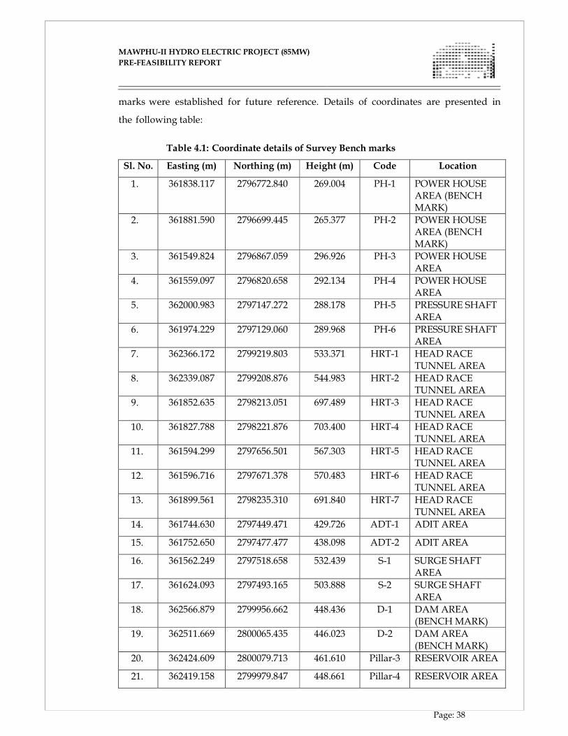
MAWPHU-II HYDRO ELECTRIC PROJECT (85MW)
MAWPHU-II HYDRO ELECTRIC PROJECT (85MW)
PRE-FEASIBILITY REPORT
Page: 38
marks were established for future reference. Details of coordinates are presented in
the following table:
Table 4.1: Coordinate details of Survey Bench marks
Sl. No. Easting (m) Northing (m) Height (m) Code Location
1. 361838.117 2796772.840 269.004 PH-1 POWER HOUSE AREA (BENCH MARK)
2. 361881.590 2796699.445 265.377 PH-2 POWER HOUSE AREA (BENCH MARK)
3. 361549.824 2796867.059 296.926 PH-3 POWER HOUSE AREA
4. 361559.097 2796820.658 292.134 PH-4 POWER HOUSE AREA
5. 362000.983 2797147.272 288.178 PH-5 PRESSURE SHAFT AREA
6. 361974.229 2797129.060 289.968 PH-6 PRESSURE SHAFT AREA
7. 362366.172 2799219.803 533.371 HRT-1 HEAD RACE TUNNEL AREA
8. 362339.087 2799208.876 544.983 HRT-2 HEAD RACE TUNNEL AREA
9. 361852.635 2798213.051 697.489 HRT-3 HEAD RACE TUNNEL AREA
10. 361827.788 2798221.876 703.400 HRT-4 HEAD RACE TUNNEL AREA
11. 361594.299 2797656.501 567.303 HRT-5 HEAD RACE TUNNEL AREA
12. 361596.716 2797671.378 570.483 HRT-6 HEAD RACE TUNNEL AREA
13. 361899.561 2798235.310 691.840 HRT-7 HEAD RACE TUNNEL AREA
14. 361744.630 2797449.471 429.726 ADT-1 ADIT AREA
15. 361752.650 2797477.477 438.098 ADT-2 ADIT AREA
16. 361562.249 2797518.658 532.439 S-1 SURGE SHAFT AREA
17. 361624.093 2797493.165 503.888 S-2 SURGE SHAFT AREA
18. 362566.879 2799956.662 448.436 D-1 DAM AREA (BENCH MARK)
19. 362511.669 2800065.435 446.023 D-2 DAM AREA (BENCH MARK)
20. 362424.609 2800079.713 461.610 Pillar-3 RESERVOIR AREA
21. 362419.158 2799979.847 448.661 Pillar-4 RESERVOIR AREA
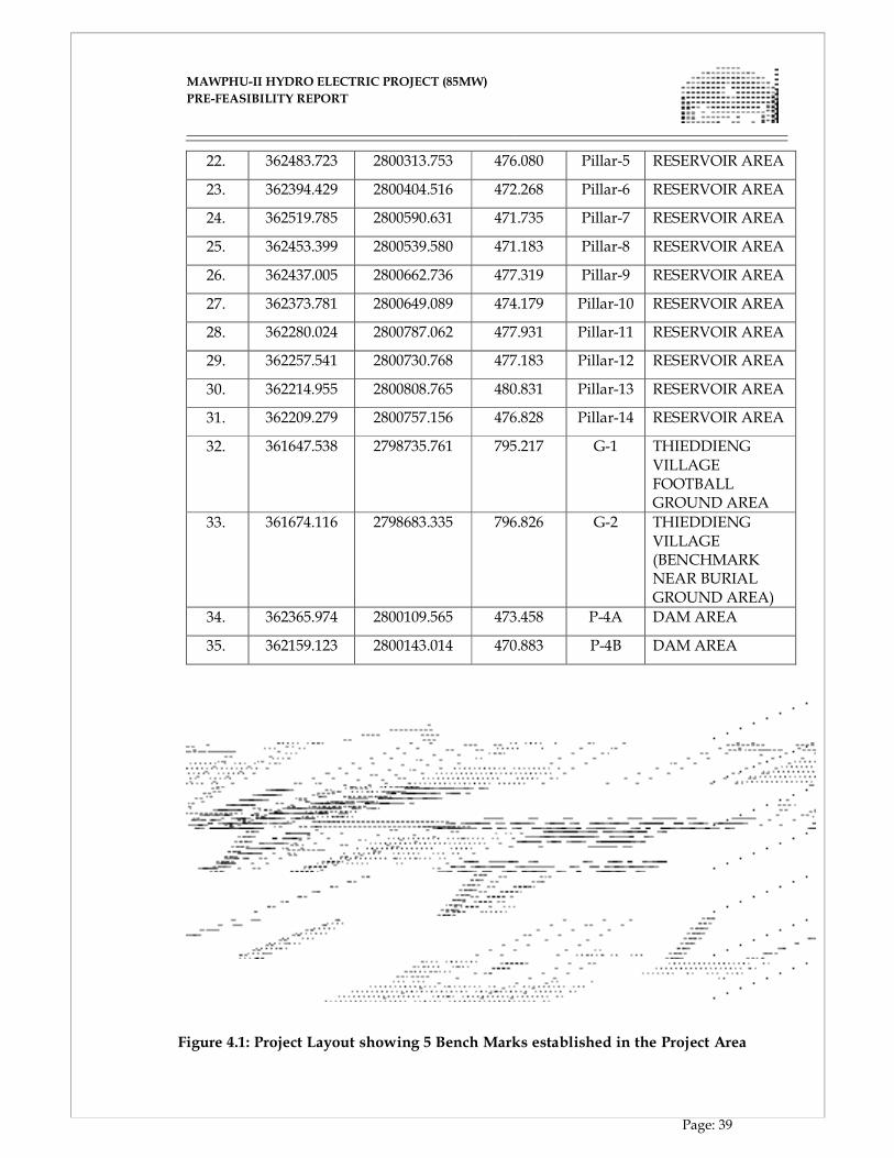
MAWPHU-II HYDRO ELECTRIC PROJECT (85MW)
MAWPHU-II HYDRO ELECTRIC PROJECT (85MW)
PRE-FEASIBILITY REPORT
Page: 39
22. 362483.723 2800313.753 476.080 Pillar-5 RESERVOIR AREA
23. 362394.429 2800404.516 472.268 Pillar-6 RESERVOIR AREA
24. 362519.785 2800590.631 471.735 Pillar-7 RESERVOIR AREA
25. 362453.399 2800539.580 471.183 Pillar-8 RESERVOIR AREA
26. 362437.005 2800662.736 477.319 Pillar-9 RESERVOIR AREA
27. 362373.781 2800649.089 474.179 Pillar-10 RESERVOIR AREA
28. 362280.024 2800787.062 477.931 Pillar-11 RESERVOIR AREA
29. 362257.541 2800730.768 477.183 Pillar-12 RESERVOIR AREA
30. 362214.955 2800808.765 480.831 Pillar-13 RESERVOIR AREA
31. 362209.279 2800757.156 476.828 Pillar-14 RESERVOIR AREA
32. 361647.538 2798735.761 795.217 G-1 THIEDDIENG VILLAGE FOOTBALL GROUND AREA
33. 361674.116 2798683.335 796.826 G-2 THIEDDIENG VILLAGE (BENCHMARK NEAR BURIAL GROUND AREA)
34. 362365.974 2800109.565 473.458 P-4A DAM AREA
35. 362159.123 2800143.014 470.883 P-4B DAM AREA
Figure 4.1: Project Layout showing 5 Bench Marks established in the Project Area
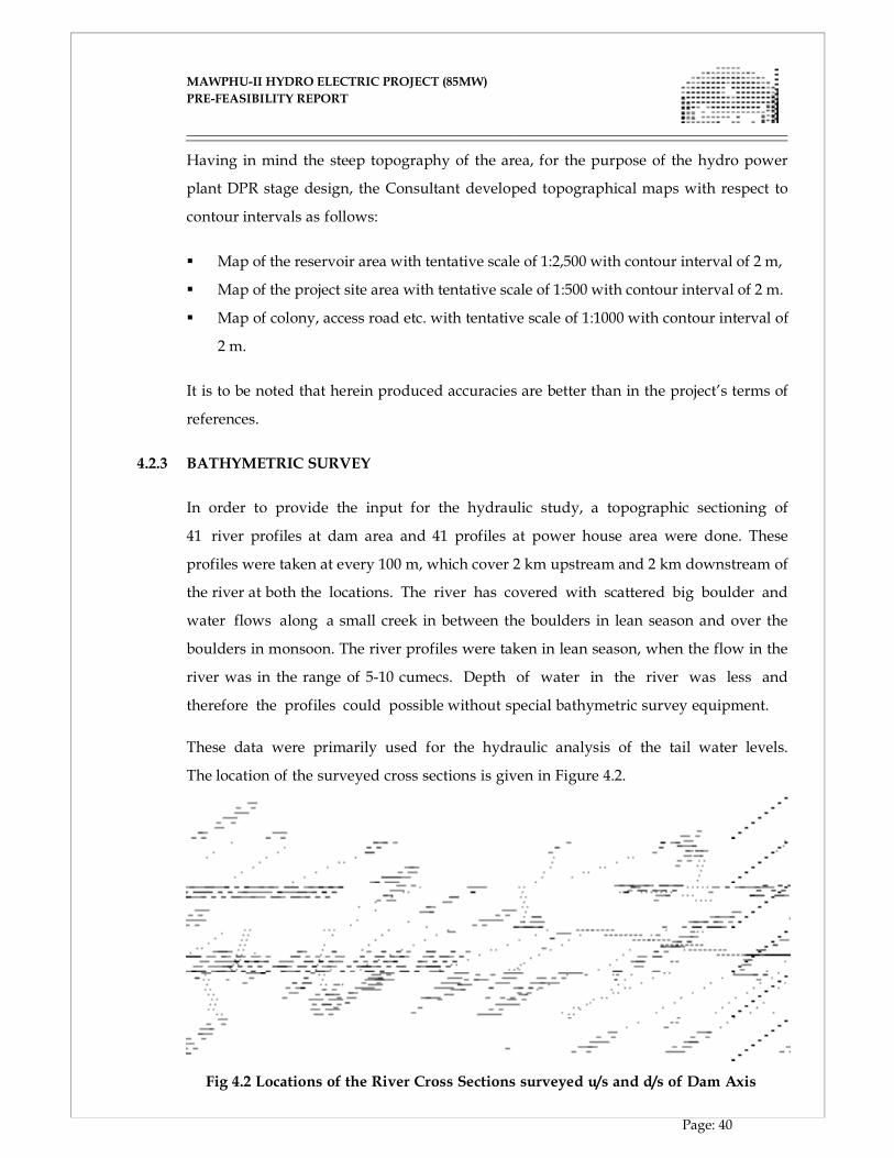
MAWPHU-II HYDRO ELECTRIC PROJECT (85MW)
MAWPHU-II HYDRO ELECTRIC PROJECT (85MW)
PRE-FEASIBILITY REPORT
Page: 40
Having in mind the steep topography of the area, for the purpose of the hydro power
plant DPR stage design, the Consultant developed topographical maps with respect to
contour intervals as follows:
� Map of the reservoir area with tentative scale of 1:2,500 with contour interval of 2 m,
� Map of the project site area with tentative scale of 1:500 with contour interval of 2 m.
� Map of colony, access road etc. with tentative scale of 1:1000 with contour interval of
2 m.
It is to be noted that herein produced accuracies are better than in the project’s terms of
references.
4.2.3 BATHYMETRIC SURVEY
In order to provide the input for the hydraulic study, a topographic sectioning of
41 river profiles at dam area and 41 profiles at power house area were done. These
profiles were taken at every 100 m, which cover 2 km upstream and 2 km downstream of
the river at both the locations. The river has covered with scattered big boulder and
water flows along a small creek in between the boulders in lean season and over the
boulders in monsoon. The river profiles were taken in lean season, when the flow in the
river was in the range of 5-10 cumecs. Depth of water in the river was less and
therefore the profiles could possible without special bathymetric survey equipment.
These data were primarily used for the hydraulic analysis of the tail water levels.
The location of the surveyed cross sections is given in Figure 4.2.
Fig 4.2 Locations of the River Cross Sections surveyed u/s and d/s of Dam Axis
MAWPHU-II HYDRO ELECTRIC PROJECT (85MW)
MAWPHU-II HYDRO ELECTRIC PROJECT (85MW)
PRE-FEASIBILITY REPORT
Page: 41
Geological and geo-technical survey and investigations including sub-surface
investigations namely exploratory drilling, drifting, in-situ and lab tests, geo-physical
survey in the project area have been presented in detail below.
4.3 SITE INVESTIGATION AND GEOLOGY
4.3.1 INTRODUCTION
The Mawphu HE Project Stage-II is located on river Umiew in the Himalayas of East
Khasi Hill district of Meghalaya. The project area falls within Archean gneiss of
Meghalaya plateau, which is characterized by wide structural and geological diversity.
The Mawphu HE Project Stage-II is a part of a cascade development scheme on
Umiew River which is the main drainage in East Khasi Hill district. It is formed at
elevation of about 1850 m. After running a considerable stretch in Meghalaya, India, it
enters into Bangladesh to reach Brahmaputra via Surma, a major tributary of River
Brahmaputra. River Umiew is joined by number of right bank tributary namely
Umkynrem, Umtong and Waisu. Approximately 232m head is available between the
dam near Mawphu village and Tail Race Tunnel outlet near Thieddieng village. The river
course is circuitous, flowing with moderately steep gradient which has been utilized for
hydropower scheme. All along its course, Umiew River flows through a narrow valley,
thus providing number of prospective sites for dam construction. River Umiew and its
tributaries are mainly rain fed. Medium to heavy rainfall in catchment area ensures
significant water availability in the river.
4.3.2 GEOLOGY OF THE PROJECT AREA
The project area falls in the central part of Meghalaya, where the Gneissic Complex has
multiple deformational & metamorphic episodes. In general, the grade of
metamorphism varies from the green schist to amphibolites facies. The Meghalaya
plateau and the Mikir hills occur in between the E-W aligned Eastern Himalaya to the
north and the broadly NNE- SSW Indo-Myanmar mobile belt to the east. The Northern
and North-eastern boundary with Bengal basin lies to its south. These geological
domains are separated from the main Himalayan belt by the Brahmaputra alluvium. The
Mikir Hills are separated from the Meghalaya Plateau by the alluvium tract of Kopili
River and the NE-SW Kopili fault.
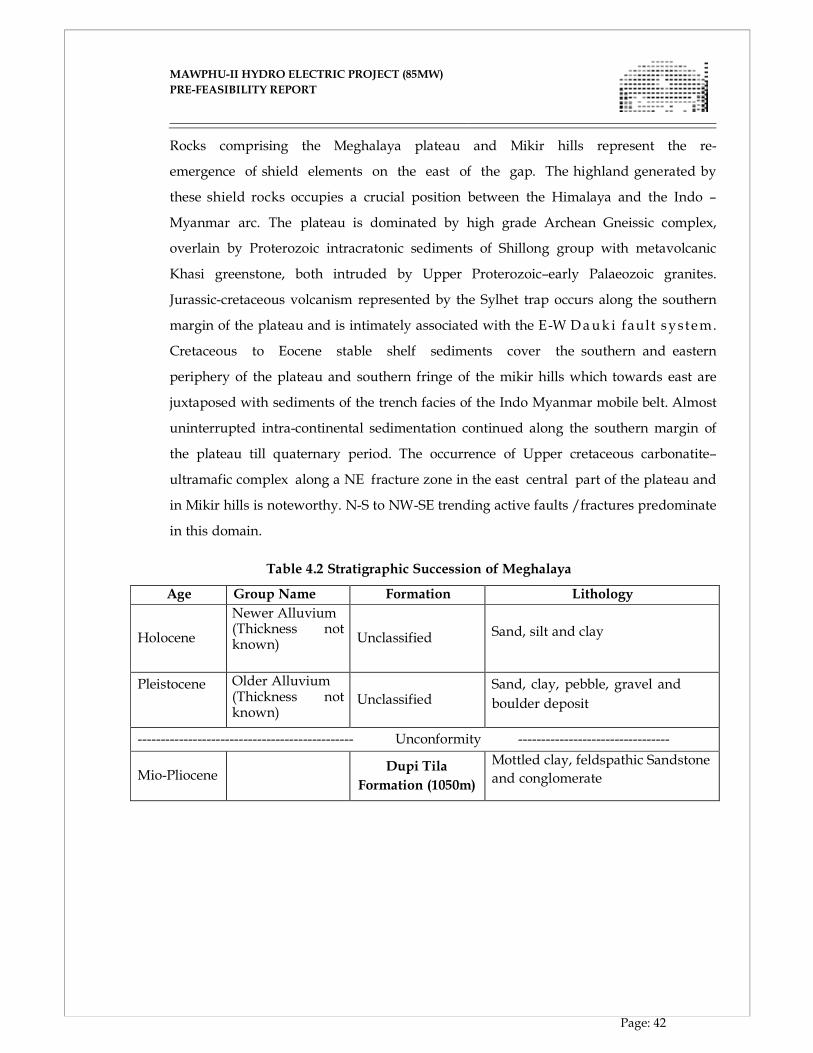
MAWPHU-II HYDRO ELECTRIC PROJECT (85MW)
MAWPHU-II HYDRO ELECTRIC PROJECT (85MW)
PRE-FEASIBILITY REPORT
Page: 42
Rocks comprising the Meghalaya plateau and Mikir hills represent the re-
emergence of shield elements on the east of the gap. The highland generated by
these shield rocks occupies a crucial position between the Himalaya and the Indo –
Myanmar arc. The plateau is dominated by high grade Archean Gneissic complex,
overlain by Proterozoic intracratonic sediments of Shillong group with metavolcanic
Khasi greenstone, both intruded by Upper Proterozoic–early Palaeozoic granites.
Jurassic-cretaceous volcanism represented by the Sylhet trap occurs along the southern
margin of the plateau and is intimately associated with the E-W Dauk i fault system.
Cretaceous to Eocene stable shelf sediments cover the southern and eastern
periphery of the plateau and southern fringe of the mikir hills which towards east are
juxtaposed with sediments of the trench facies of the Indo Myanmar mobile belt. Almost
uninterrupted intra-continental sedimentation continued along the southern margin of
the plateau till quaternary period. The occurrence of Upper cretaceous carbonatite–
ultramafic complex along a NE fracture zone in the east central part of the plateau and
in Mikir hills is noteworthy. N-S to NW-SE trending active faults /fractures predominate
in this domain.
Table 4.2 Stratigraphic Succession of Meghalaya
Age Group Name Formation Lithology Holocene
Newer Alluvium (Thickness not known)
Unclassified
Sand, silt and clay
Pleistocene Older Alluvium (Thickness not known)
Unclassified
Sand, clay, pebble, gravel and
boulder deposit
----------------------------------------------- Unconformity ---------------------------------
Mio-Pliocene
Dupi Tila
Formation (1050m)
Mottled clay, feldspathic Sandstone
and conglomerate
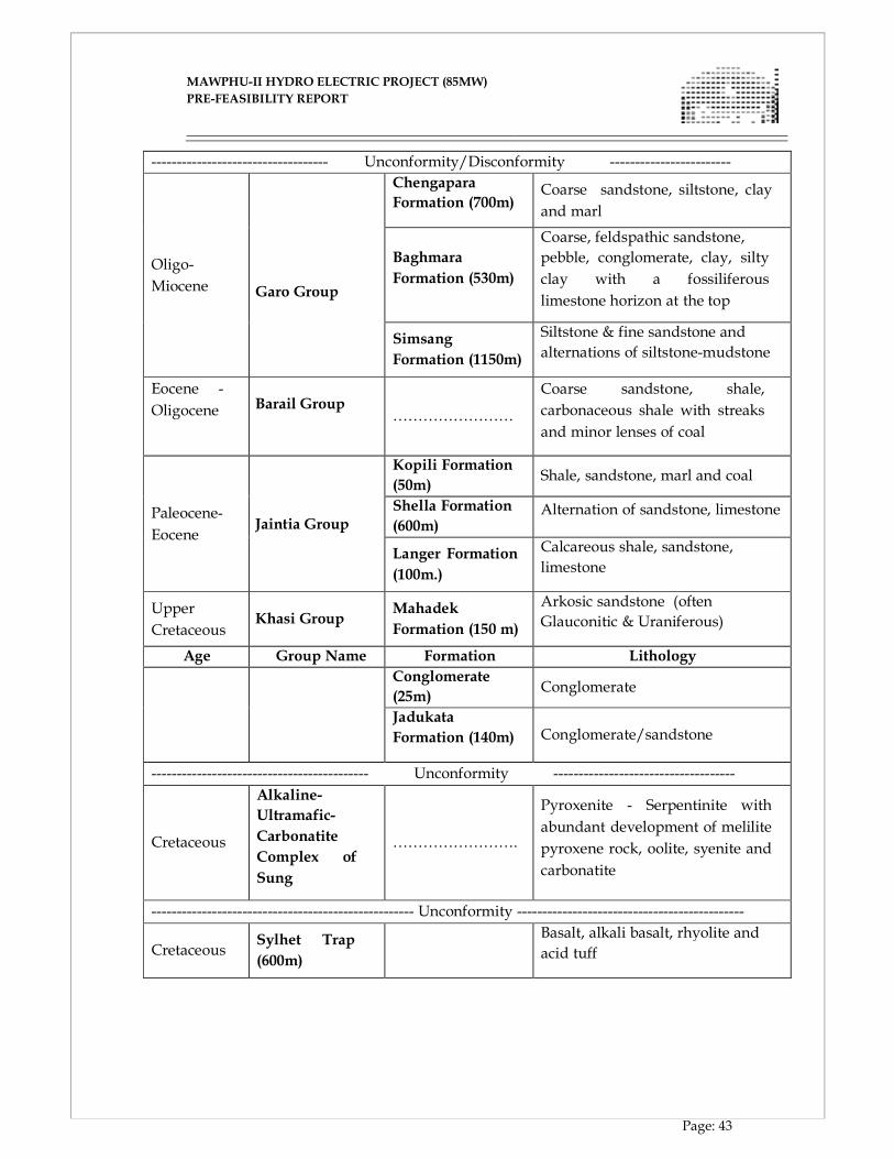
MAWPHU-II HYDRO ELECTRIC PROJECT (85MW)
MAWPHU-II HYDRO ELECTRIC PROJECT (85MW)
PRE-FEASIBILITY REPORT
Page: 43
----------------------------------- Unconformity/Disconformity ------------------------ Oligo-
Miocene
Garo Group
Chengapara
Formation (700m) Coarse sandstone, siltstone, clay
and marl
Baghmara
Formation (530m)
Coarse, feldspathic sandstone,
pebble, conglomerate, clay, silty
clay with a fossiliferous
limestone horizon at the top
Simsang
Formation (1150m)
Siltstone & fine sandstone and
alternations of siltstone-mudstone
Eocene -
Oligocene
Barail Group
……………………
Coarse sandstone, shale,
carbonaceous shale with streaks
and minor lenses of coal
Paleocene-
Eocene Jaintia Group
Kopili Formation
(50m)
Shale, sandstone, marl and coal
Shella Formation
(600m) Alternation of sandstone, limestone
Langer Formation
(100m.)
Calcareous shale, sandstone,
limestone
Upper
Cretaceous
Khasi Group
Mahadek
Formation (150 m)
Arkosic sandstone (often
Glauconitic & Uraniferous)
Age Group Name Formation Lithology
Conglomerate
(25m)
Conglomerate
Jadukata
Formation (140m)
Conglomerate/sandstone
------------------------------------------- Unconformity ------------------------------------ Cretaceous
Alkaline-
Ultramafic-
Carbonatite
Complex of
Sung
…………………….
Pyroxenite - Serpentinite with
abundant development of melilite
pyroxene rock, oolite, syenite and
carbonatite
---------------------------------------------------- Unconformity ---------------------------------------------
Cretaceous
Sylhet Trap
(600m)
Basalt, alkali basalt, rhyolite and
acid tuff
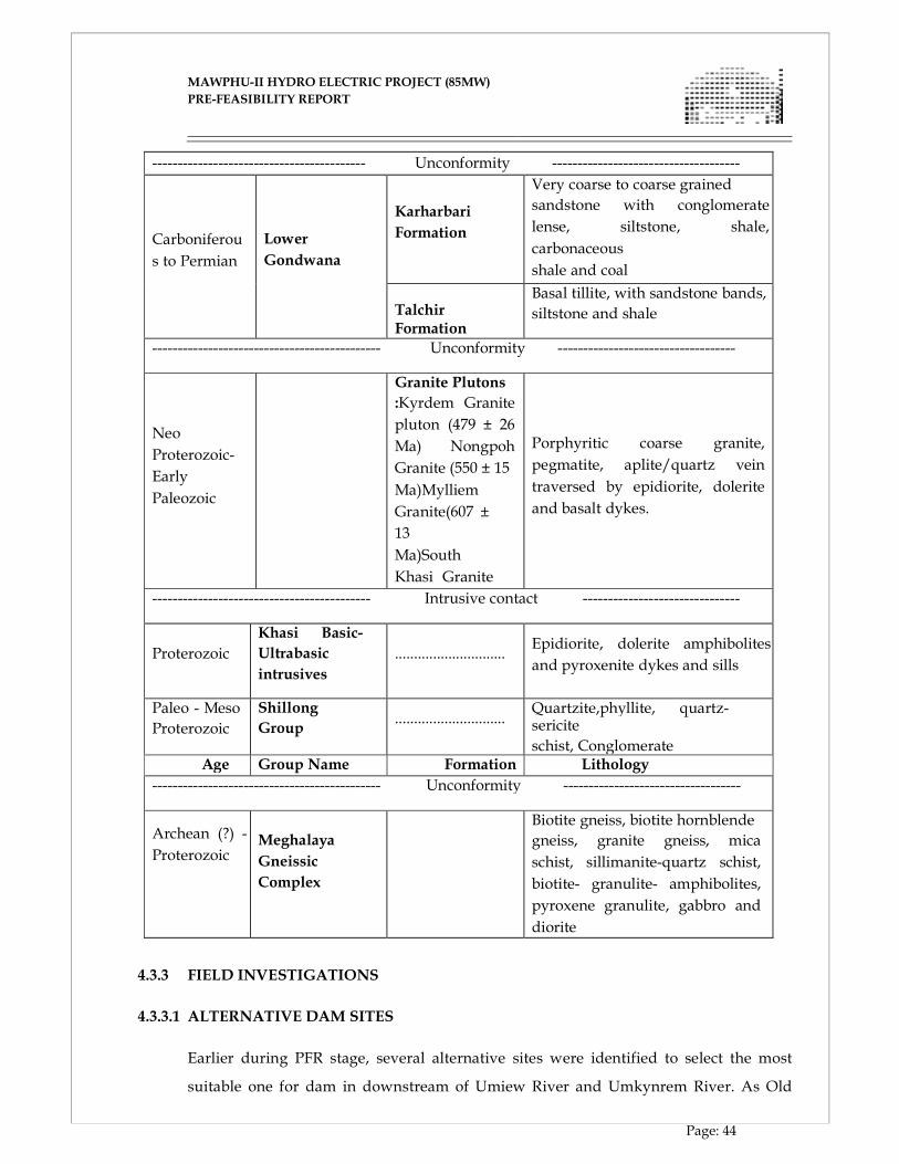
MAWPHU-II HYDRO ELECTRIC PROJECT (85MW)
MAWPHU-II HYDRO ELECTRIC PROJECT (85MW)
PRE-FEASIBILITY REPORT
Page: 44
------------------------------------------ Unconformity ------------------------------------- Carboniferou
s to Permian
Lower
Gondwana
Karharbari
Formation
Very coarse to coarse grained
sandstone with conglomerate
lense, siltstone, shale,
carbonaceous
shale and coal
Talchir Formation
Basal tillite, with sandstone bands,
siltstone and shale
--------------------------------------------- Unconformity -----------------------------------
Neo
Proterozoic-
Early
Paleozoic
Granite Plutons
:Kyrdem Granite
pluton (479 ± 26
Ma) Nongpoh
Granite (550 ± 15
Ma)Mylliem
Granite(607 ±
13
Ma)South
Khasi Granite
Porphyritic coarse granite,
pegmatite, aplite/quartz vein
traversed by epidiorite, dolerite
and basalt dykes.
------------------------------------------- Intrusive contact -------------------------------
Proterozoic
Khasi Basic-
Ultrabasic
intrusives
.............................
Epidiorite, dolerite amphibolites
and pyroxenite dykes and sills
Paleo - Meso
Proterozoic
Shillong
Group
.............................
Quartzite,phyllite, quartz-sericite
schist, Conglomerate Age Group Name Formation Lithology
--------------------------------------------- Unconformity -----------------------------------
Archean (?) -
Proterozoic
Meghalaya
Gneissic
Complex
Biotite gneiss, biotite hornblende
gneiss, granite gneiss, mica
schist, sillimanite-quartz schist,
biotite- granulite- amphibolites,
pyroxene granulite, gabbro and
diorite
4.3.3 FIELD INVESTIGATIONS
4.3.3.1 ALTERNATIVE DAM SITES
Earlier during PFR stage, several alternative sites were identified to select the most
suitable one for dam in downstream of Umiew River and Umkynrem River. As Old
MAWPHU-II HYDRO ELECTRIC PROJECT (85MW)
MAWPHU-II HYDRO ELECTRIC PROJECT (85MW)
PRE-FEASIBILITY REPORT
Page: 45
PFR Dam location proposed by NEEPCO does not fulfill the environmental
requirement formulated by Expert Appraisal Committee (EAC) of MoEF, Alt-1, Alt. 2 &
Alt.3 were chosen for review during site visit. It was found that Alt-3 was a suitable
location which is at about 3.1km downstream of proposed Umduna HEP Power House
location and accordingly an exploration plan was drawn at the axis for investigation for
DPR preparation.
The identification of the Dam alternatives was done from the existing right bank
footrack and left bank foot rack based on general topography, presence of suitable
abutments and availability of sufficient head. As the river is flowing through number
of sharp bends, the dam alternative sites were identified immediately downstream of
such bends so that a reasonable straight reach would remain available in downstream
so as to accommodate the energy dissipation arrangement.
Following locations have been considered for Dam
1. Old PFR Location (about 1km downstream of proposed
Power House location of upstream project - Umduna HEP)
2. Alt-1 about 2km downstream of Umduna HEP Power House
Location
3. Alt-2 about 2.5km downstream of Umduna HEP Power House
Location
4. Alt-3 about 3.1km downstream of Umduna HEP Power House
Location
5. Alt-3A about 70m downstream of Alt-3 location
During drilling at Alt-3 location, drill hole DH-07 encountered deep overburden on
the left bank of dam axis. So, it was proposed that the dam axis needs to be shifted
slightly downstream by about 70m to avoid deep overburden on the left abutment.
Accordingly, Alt- 3A has been chosen as a possible location for further investigation
works.
4.3.3.2 GEOLOGICAL MAPPING
The Proposed project component have been geologically mapped and studied by EIPL
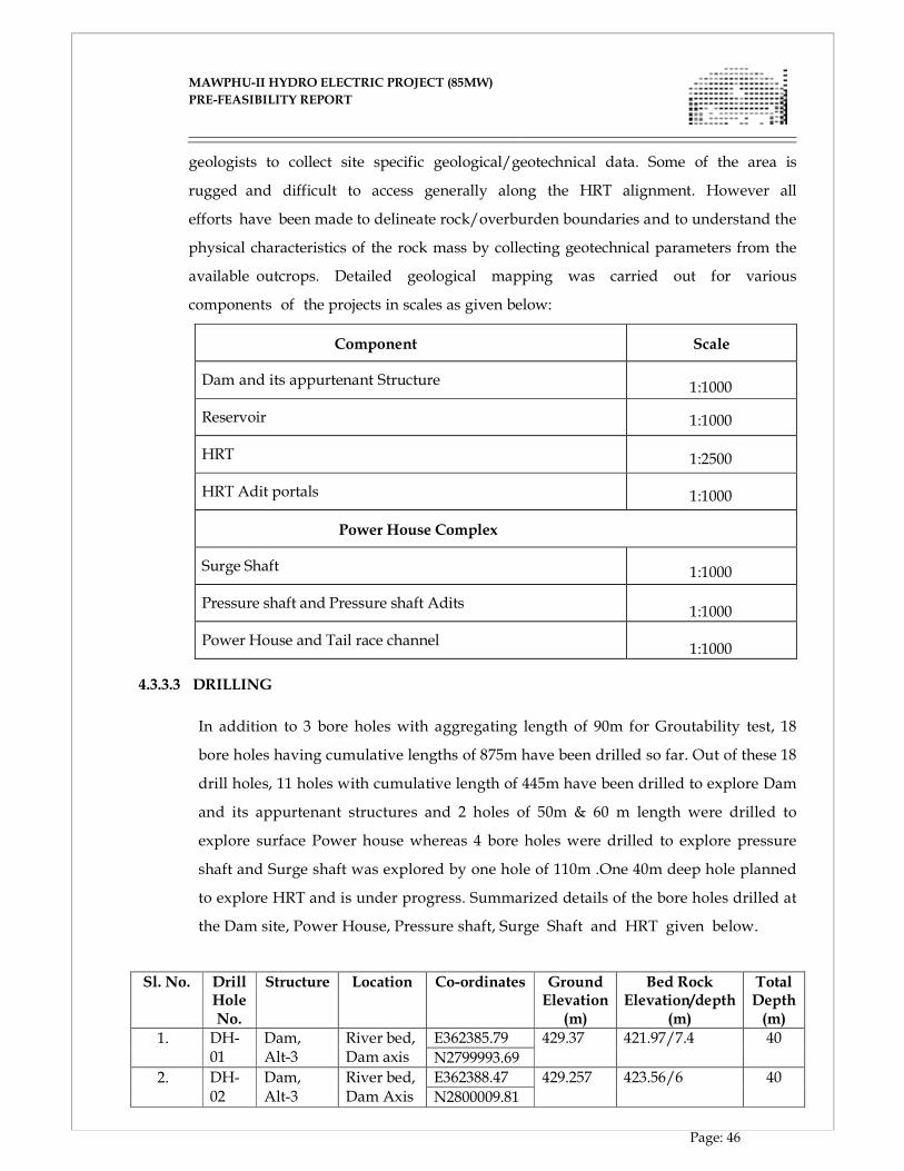
MAWPHU-II HYDRO ELECTRIC PROJECT (85MW)
MAWPHU-II HYDRO ELECTRIC PROJECT (85MW)
PRE-FEASIBILITY REPORT
Page: 46
geologists to collect site specific geological/geotechnical data. Some of the area is
rugged and difficult to access generally along the HRT alignment. However all
efforts have been made to delineate rock/overburden boundaries and to understand the
physical characteristics of the rock mass by collecting geotechnical parameters from the
available outcrops. Detailed geological mapping was carried out for various
components of the projects in scales as given below:
Component Scale
Dam and its appurtenant Structure
1:1000
Reservoir 1:1000
HRT
1:2500
HRT Adit portals
1:1000
Power House Complex
Surge Shaft
1:1000
Pressure shaft and Pressure shaft Adits
1:1000
Power House and Tail race channel
1:1000 4.3.3.3 DRILLING
In addition to 3 bore holes with aggregating length of 90m for Groutability test, 18
bore holes having cumulative lengths of 875m have been drilled so far. Out of these 18
drill holes, 11 holes with cumulative length of 445m have been drilled to explore Dam
and its appurtenant structures and 2 holes of 50m & 60 m length were drilled to
explore surface Power house whereas 4 bore holes were drilled to explore pressure
shaft and Surge shaft was explored by one hole of 110m .One 40m deep hole planned
to explore HRT and is under progress. Summarized details of the bore holes drilled at
the Dam site, Power House, Pressure shaft, Surge Shaft and HRT given below.
Sl. No. Drill Hole No.
Structure Location Co-ordinates Ground Elevation
(m)
Bed Rock Elevation/depth
(m)
Total Depth (m)
1. DH-01
Dam, Alt-3
River bed, Dam axis
E362385.79 429.37 421.97/7.4 40
N2799993.69
2. DH-02
Dam, Alt-3
River bed, Dam Axis
E362388.47 429.257 423.56/6 40
N2800009.81
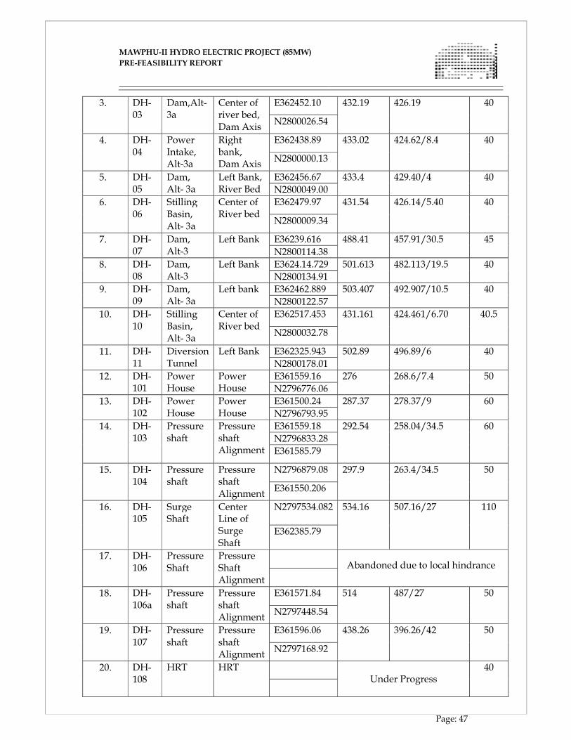
MAWPHU-II HYDRO ELECTRIC PROJECT (85MW)
MAWPHU-II HYDRO ELECTRIC PROJECT (85MW)
PRE-FEASIBILITY REPORT
Page: 47
3. DH-03
Dam,Alt- 3a
Center of river bed, Dam Axis
E362452.10 432.19 426.19 40
N2800026.54
4. DH-04
Power Intake, Alt-3a
Right bank, Dam Axis
E362438.89 433.02 424.62/8.4 40
N2800000.13
5. DH-05
Dam, Alt- 3a
Left Bank, River Bed
E362456.67 433.4 429.40/4 40
N2800049.00
6. DH-06
Stilling Basin, Alt- 3a
Center of River bed
E362479.97 431.54 426.14/5.40 40
N2800009.34
7. DH-07
Dam, Alt-3
Left Bank E36239.616 488.41 457.91/30.5 45
N2800114.38
8. DH-08
Dam, Alt-3
Left Bank E3624.14.729 501.613 482.113/19.5 40
N2800134.91
9. DH-09
Dam, Alt- 3a
Left bank E362462.889 503.407 492.907/10.5 40
N2800122.57
10. DH-10
Stilling Basin, Alt- 3a
Center of River bed
E362517.453 431.161 424.461/6.70 40.5
N2800032.78
11. DH-11
Diversion Tunnel
Left Bank E362325.943 502.89 496.89/6 40
N2800178.01
12. DH-101
Power House
Power House
E361559.16 276 268.6/7.4 50
N2796776.06
13. DH-102
Power House
Power House
E361500.24 287.37 278.37/9 60
N2796793.95
14. DH-103
Pressure shaft
Pressure shaft Alignment
E361559.18 292.54 258.04/34.5 60
N2796833.28
E361585.79
15. DH-104
Pressure shaft
Pressure shaft Alignment
N2796879.08 297.9 263.4/34.5 50
E361550.206
16. DH-105
Surge Shaft
Center Line of Surge Shaft
N2797534.082 534.16 507.16/27 110
E362385.79
17. DH-106
Pressure Shaft
Pressure Shaft Alignment
Abandoned due to local hindrance
18. DH-106a
Pressure shaft
Pressure shaft Alignment
E361571.84 514 487/27 50
N2797448.54
19. DH-107
Pressure shaft
Pressure shaft Alignment
E361596.06 438.26 396.26/42 50
N2797168.92
20. DH-108
HRT HRT Under Progress
40
MAWPHU-II HYDRO ELECTRIC PROJECT (85MW)
MAWPHU-II HYDRO ELECTRIC PROJECT (85MW)
PRE-FEASIBILITY REPORT
Page: 48
4.3.3.4 WATER PRESSURE/ PERMEABILITY TESTS
In total 402 numbers of water pressure tests were conducted for assessing
permeability in all the exploratory drill holes .Water Pressure Tests in bedrock were
conducted using double packer in 3m stages in ascending order as per IS 5529(Part -
II).Reporting Lugeon values were determined by Houlsby A.C(1974) method. Water was
pumped at steady rate and constant pressure for periods of 5 minutes. A cycle of water
pressure tests have been conducted on the same stage at varying pressures. Reporting
Lugeon values have been incorporated in the drill hole logs. Permeability tests in
overburden were conducted by constant head method as per IS: 5529(Part – I) and has
incorporated in the drill hole logs.
4.3.3.5 SPT
In total 106 numbers of Standard penetration test were conducted for assessing bearing
capacity of overburden, SPT were conducted in accordance with IS 2131 and results
were incorporated in the respective drill logs.
4.3.3.6 GROUTABILITY TEST
Groutability test has been carried out on the river bed (Dam foundation) to
ascertain the extent of amenability of foundation rock to systematic grouting. The
pattern and depth of hole is governed primarily by the design requirement and the
nature of rock. Giving due cognizance to variation of strike of foliation and other
intersecting joints Triangular pattern was adopted for conducting Groutability test.
4.3.3.7 EXPLORATORY DRIFTING
The dam abutments of Alternative-3a have been planned to be investigated by
excavating two drifts.viz LBD-1 having 30m length at left bank and RBD-1 having
30m length at left bank. A total length of 60m of drifting at the Dam location been
proposed to be carried out.
4.3.3.8 ROCK MECHANIC TESTS
In order to determine both physio mechanical and engineering properties such as specific
gravity, UCS, tensile strength, cohesion, friction angle, deformation modulus of the
various rock types occurring in the project area, laboratory tests on rock cores
collected from drill holes were carried out at the ATES laboratory.
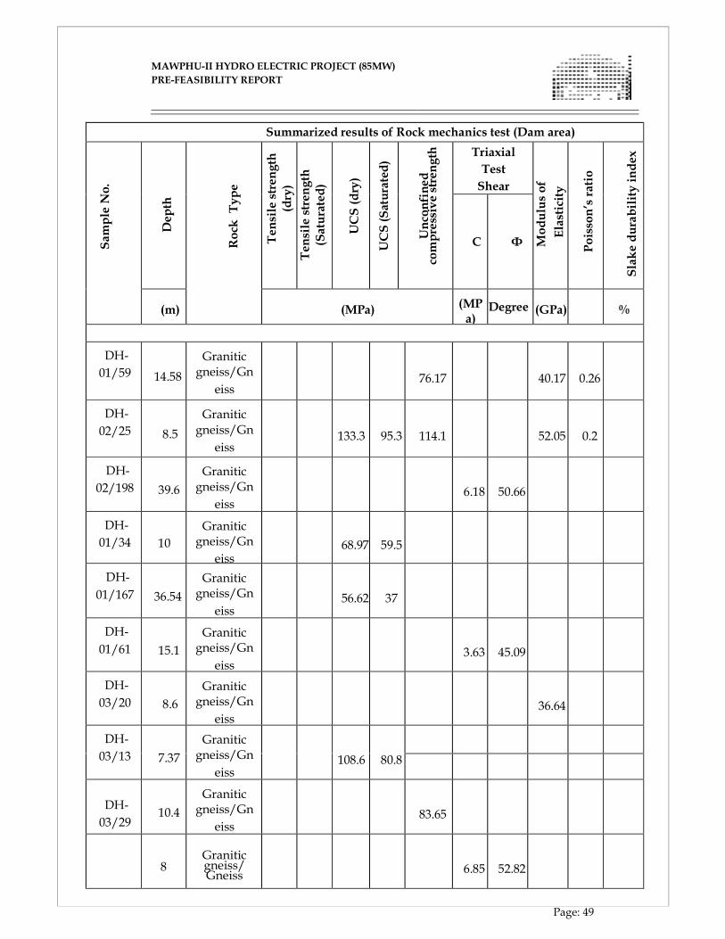
MAWPHU-II HYDRO ELECTRIC PROJECT (85MW)
MAWPHU-II HYDRO ELECTRIC PROJECT (85MW)
PRE-FEASIBILITY REPORT
Page: 49
Summarized results of Rock mechanics test (Dam area)
Sam
ple N
o.
Dep
th
Rock
Type
Ten
sile stren
gth
(dry)
Ten
sile stren
gth
(Saturated)
UCS (dry)
UCS (Saturated)
Unconfined
compressive strength
Triaxial
Test
Shear
Modulus of
Elasticity
Poisson’s ratio
Slake durability index
C Φ
(m)
(MPa)
(MP a)
Degree
(GPa) %
DH-
01/59 14.58
Granitic gneiss/Gn
eiss
76.17
40.17
0.26
DH-
02/25 8.5
Granitic gneiss/Gn
eiss
133.3 95.3
114.1
52.05 0.2
DH-
02/198 39.6
Granitic gneiss/Gn
eiss
6.18
50.66
DH-
01/34 10
Granitic gneiss/Gn
eiss
68.97 59.5
DH-
01/167 36.54
Granitic gneiss/Gn
eiss
56.62 37
DH-
01/61 15.1
Granitic gneiss/Gn
eiss
3.63
45.09
DH-
03/20 8.6
Granitic gneiss/Gn
eiss
36.64
DH-
03/13 7.37
Granitic gneiss/Gn
eiss
108.6 80.8
DH-
03/29
10.4
Granitic gneiss/Gn
eiss
83.65
DH-
8
Granitic gneiss/Gneiss
6.85
52.82
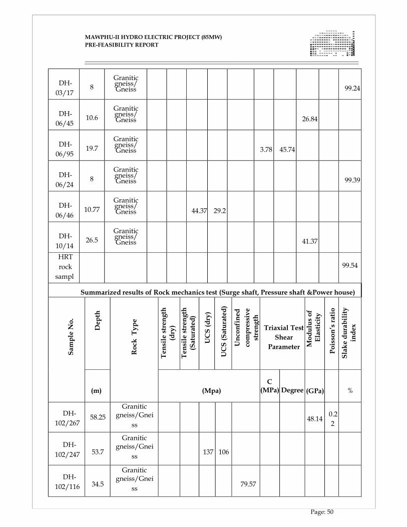
MAWPHU-II HYDRO ELECTRIC PROJECT (85MW)
MAWPHU-II HYDRO ELECTRIC PROJECT (85MW)
PRE-FEASIBILITY REPORT
Page: 50
DH-
03/17
8
Granitic gneiss/Gneiss
99.24
DH-
06/45
10.6
Granitic gneiss/Gneiss
26.84
DH-
06/95
19.7
Granitic gneiss/Gneiss
3.78
45.74
DH-
06/24
8
Granitic gneiss/Gneiss
99.39
DH-
06/46
10.77
Granitic gneiss/Gneiss
44.37 29.2
DH-
10/14
4
26.5
Granitic gneiss/Gneiss
41.37
HRT
rock
sampl
e
99.54
Summarized results of Rock mechanics test (Surge shaft, Pressure shaft &Power house)
Sam
ple N
o.
Dep
th
Rock
Type
Tensile stren
gth
(dry)
Tensile stren
gth
(Saturated)
UCS (dry)
UCS (Saturated)
Unconfined
compressive
strength
Triaxial Test
Shear
Parameter Modulus of
Elasticity
Poisson’s ratio
Slake durability
index
(m)
(Mpa)
C (MPa)
Degree
(GPa)
%
DH-
102/267 58.25
Granitic gneiss/Gnei
ss
48.14
0.2
2
DH-
102/247
53.7
Granitic gneiss/Gnei
ss
137
106
DH-
102/116
34.5
Granitic gneiss/Gnei
ss
79.57
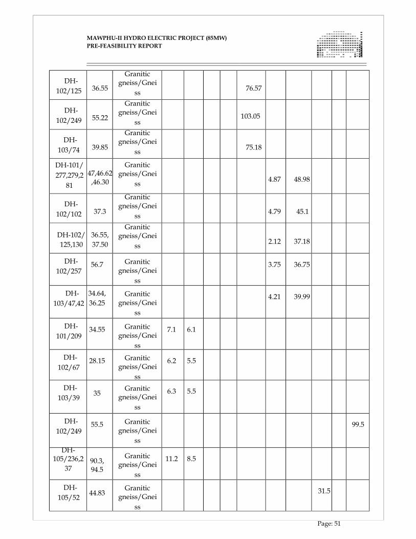
MAWPHU-II HYDRO ELECTRIC PROJECT (85MW)
MAWPHU-II HYDRO ELECTRIC PROJECT (85MW)
PRE-FEASIBILITY REPORT
Page: 51
DH-
102/125
36.55
Granitic gneiss/Gnei
ss
76.57
DH-
102/249
55.22
Granitic gneiss/Gnei
ss
103.05
DH-
103/74
39.85
Granitic gneiss/Gnei
ss
75.18
DH-101/
277,279,2
81
47,46.62,46.30
Granitic gneiss/Gnei
ss
4.87
48.98
DH-
102/102
37.3
Granitic gneiss/Gnei
ss
4.79
45.1
DH-102/
125,130
36.55,
37.50
Granitic gneiss/Gnei
ss
2.12
37.18
DH-
102/257
56.7
Granitic
gneiss/Gnei
ss
3.75
36.75
DH-
103/47,42
34.64,
36.25
Granitic
gneiss/Gnei
ss
4.21
39.99
DH-
101/209
34.55
Granitic
gneiss/Gnei
ss
7.1
6.1
DH-
102/67
28.15
Granitic
gneiss/Gnei
ss
6.2
5.5
DH-
103/39
35
Granitic
gneiss/Gnei
ss
6.3
5.5
DH-
102/249
55.5
Granitic
gneiss/Gnei
ss
99.5
DH- 105/236,2
37
90.3, 94.5
Granitic
gneiss/Gnei
ss
11.2
8.5
DH-
105/52
44.83
Granitic
gneiss/Gnei
ss
31.5
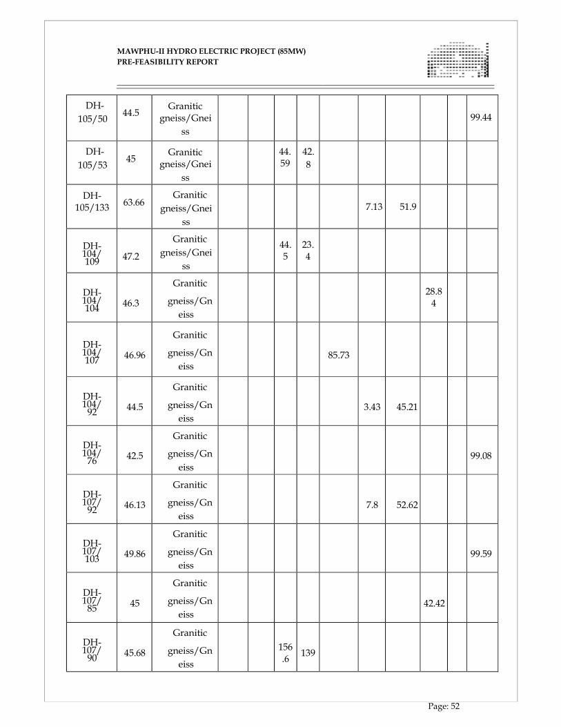
MAWPHU-II HYDRO ELECTRIC PROJECT (85MW)
MAWPHU-II HYDRO ELECTRIC PROJECT (85MW)
PRE-FEASIBILITY REPORT
Page: 52
DH-
105/50
44.5
Granitic
gneiss/Gnei
ss
99.44
DH-
105/53
45
Granitic
gneiss/Gnei
ss
44. 59
42.
8
DH- 105/133
63.66
Granitic
gneiss/Gnei
ss
7.13
51.9
DH- 104/109
47.2
Granitic
gneiss/Gnei
ss
44. 5
23. 4
DH- 104/104
46.3
Granitic
gneiss/Gn
eiss
28.8 4
DH- 104/107
46.96
Granitic
gneiss/Gn
eiss
85.73
DH- 104/92
44.5
Granitic
gneiss/Gn
eiss
3.43
45.21
DH- 104/76
42.5
Granitic
gneiss/Gn
eiss
99.08
DH- 107/92
46.13
Granitic
gneiss/Gn
eiss
7.8
52.62
DH- 107/103
49.86
Granitic
gneiss/Gn
eiss
99.59
DH- 107/85
45
Granitic
gneiss/Gn
eiss
42.42
DH- 107/90
45.68
Granitic
gneiss/Gn
eiss
156 .6
139
MAWPHU-II HYDRO ELECTRIC PROJECT (85MW)
MAWPHU-II HYDRO ELECTRIC PROJECT (85MW)
PRE-FEASIBILITY REPORT
Page: 53
DH- 107/92
46.13
Granitic
gneiss/Gn
eiss
112.6
4.3.3.9 PETROGRAPHY
Specimens of rocks obtained from various rock exposures and rock cores from various
drill holes of Dam site, Surge Shaft and surface Power House were utilized by the GSI
Petrology Laboratory located at Faridabad for Petrographical studies. Furthermore, 2 silt
samples were also tested and 2 tests are under progress in same laboratory for estimating
of mineral distribution in silt samples.
4.3.3.10 GEOPHYSICAL STUDIES
Geophysical explorations involving seismic refraction profiling were carried out in the
project area with a view to decipher the interface between the overburden and bedrock
as well as to determine the overburden/bedrock characteristics. In total 7 profiles
aggregating length of 860m covering Dam, Power house and adit has been carried out.
4.3.3.11 SEISMOLOGICAL STUDIES
The project is located in North Eastern region of India which falls in Zone V of the
seismic zoning map of India and is considered to be seismically active region. Analysis of
the earthquake data obtained from different sources reveals that 137 major
earthquakes shocked the area from 1845 to 1980. For a large number of events depths
of hypocenters are not known which has limited the scope of the present study to
some extent. For better understanding of the Seismicity of project area, Dept of
Earthquake Engineering IIT Roorkee was entrusted the job to carry out the study for
evaluating seismic design parameters for the project components. Based on the above,
the maximum value estimated for horizontal peak ground acceleration(PGA) is 0.42gfor
MCE and 0.24 for DBE condition respectively for both Horizontal and Vertical ground
motion.
4.4 GEOTECHNICAL EVALUATION OF CIVIL STRUCTURES
4.4.1 DAM
The 51m high concrete dam, from deepest foundation level, shall have a length of
MAWPHU-II HYDRO ELECTRIC PROJECT (85MW)
MAWPHU-II HYDRO ELECTRIC PROJECT (85MW)
PRE-FEASIBILITY REPORT
Page: 54
139.85m at the top. The top of the dam has been kept at El. 472m. The FRL is expected to
be at El. 470m with a submergence area at FRL of 13 hectares. The river channel flows at
the center while right bank and left flank hugging water way are occupied by River
borne deposits. The river bed is occupied by large pell mell boulders of size varying from
0.5 to 6-7m, some of these large boulders could be colluvial blocks. The river bed was
explored by six drill holes i.e. DH-01, DH-02, DH-03, DH-05, DH-06 and DH-10.
Based on the above drill hole data it is inferred that in the river bed area, overburden
which is mainly RBM, thickness of which varies from 4m to 7.4m. Permeability values
range from 1-6 Lugeon and suggests reasonably tight foundation condition in the
riverbed. In any of the drill hole no major fracture zone or crushed/shear zone was
encountered, making it suitable for laying concrete dam.
On the right bank, the abutment between river bed level (El. 434 m) and El. 530 m is
approximately 55°. Along the right bank, rock outcrops of fine to medium grained
granite gneiss are occurring near the river water line were delineated in the
upstream and downstream of the dam axis. At right bank few thick veins of
pegmatite were encountered during the surface mapping. In the course of the abutment
excavation, no major problem is foreseen as right bank exposes strong granite gneiss
upto EL.510m and beyond the top of dam(EL.472m).No adverse zone was observed
during surface mapping of right bank.
The left bank abutment slopes at 52° to 55° between river level (El. 436 m) and El. 480
m, and subsequently flattens to 40° till El. 520 m. Upto elevation of 460m from river
bed level (El. 434m), rock is exposed on the left bank then above that, it is covered
by overburden material constituted of slope wash comprising top soil and rounded to
sub-rounded pebble to boulder grade detritus of granite gneiss, pink granite, grey granite
and quartzite in a sandy to silty matrix. Granitic gneiss belonging to Archean gneissic
complex are exposed here. Bedrock exposures are visible till El 460m after which the
slope is covered by hill wash deposits comprising rounded to sub-rounded cobble,
pebble and boulder of granite gneiss, pink granite, grey granite in a sandy to silty
matrix. The thickness of the overburden has been seen to ranges between 10.5m to
30.5m as has been observed from drill hole DH-07, DH-08 and DH-09. In DH-07,
overburden thickness of 30.5m comprising unsorted assemblage of rounded to
sub-rounded pebble to boulder grade detritus of granite gneiss, pink granite, grey
MAWPHU-II HYDRO ELECTRIC PROJECT (85MW)
MAWPHU-II HYDRO ELECTRIC PROJECT (85MW)
PRE-FEASIBILITY REPORT
Page: 55
granite and quartzite in a sandy to silty matrix was encountered. In DH-07 water table
was encountered at 30.10m depth having corresponding El. 458.31m. Such depressed bed
rock profile indicates possible scouring/erosion of bed rock close to concave side of the
curvature along the river beyond the rock ledge. In view of such thick overburden and
to know the lateral extent of depressed rock profile, DH-08 was drilled 40 m towards
hillside from the DH-07 on dam axis Alt-3. Here also overburden of 19.5m was
intersected with corresponding (El 482.11m). In view of such thick overburden, it was
decided to shift to dam to downstream. To know the possible extent of the depression
in downstream side of the left bank a drill hole DH-09 was proposed at 70m downstream
from earlier Dam axis. In DH-09, overburden thickness of 10.5m EL.492m was
encountered which is above the level of the top of the dam. An assemblage of
rounded to sub rounded pebble to boulder of pink granite, gneiss and quartzite was
intersected. Here in overburden, a thick patch of sand was encountered at 3m to 6m
depth. Water table was not encountered in this drill hole. Accordingly, dam axis was
shifted to new location Alt-3a located 70m downstream of previously proposed dam
axis, Alt-3.
4.4.2 ENERGY DISSIPATOR
The energy dissipater area has been explored by a drill hole DH-06 and DH-10
located at the center of the river channel. Based on the drill hole data it is assessed
that at the flip bucket the overburden depth, comprising riverine would be between
5.4m to 6.70m.The underlying bedrock shall be of dominantly fine to coarse grained
granitic gneiss. After removing the bedrock a stripping depth of approx. 2-3m is
envisaged. The Insitu permeability values of 1.86 to 3.25 Lugeon suggest fairly tight
foundation conditions and the same gets corroborate through the results of Groutability
test.
4.4.3 COFFER DAM 4.4.3.1 UPSTREAM COFFER DAM
An Eighteen m high coffer dam has been proposed about 205 upstream of dam axis for
diversion of water through diversion tunnel. Surface geological mapping reveals the
presence of isolated patches of bedrock represented by quartz biotite gneiss and
gneiss on the surface on the left flank of the coffer dam whereas on the right flank
continuous outcrop of gneiss are well exposed. In the river bed portion, as revealed
MAWPHU-II HYDRO ELECTRIC PROJECT (85MW)
MAWPHU-II HYDRO ELECTRIC PROJECT (85MW)
PRE-FEASIBILITY REPORT
Page: 56
from the seismic survey the overburden thickness shall range from 7 m to 17m. On the
basis of various boreholes drilled in the dam area particularly DH-01 and DH-02,
overburden permeability is expected to range between 1.02 to 1.2 X 10⁻² cm/sec. Wheres
that of bedrock would vary between 3 to 6 Lugeon. In view of this as seepage
control measure jet grouting provisions has been kept below the coffer dam to minimize
seepage into the dam pit during construction.
4.4.3.2 DOWNSTREAM COFFER DAM
Downstream Coffer dam has been proposed to be located at 160m D/S of dam axis, right
abutment of the structure has been positioned utilizing the exposed rock ledge. DH-10
drilled for subsurface investigation of the stilling basin, it is opined that thickness of
overburdened, constituted of large boulder pebbles, cobbles, gravels of granite/granitic
gneiss mixed with sand shall be of the order of 5 to 7m and shall be followed by strong to
very strong bed rock quartz biotite gneiss. Overburden permeability is anticipated to
range between 3.8 to 4.8X10⁻³ cm/sec and therefore suitable pumping arrangement
shall be required during construction.
4.4.4 DIVERSION TUNNEL
During the construction, the river water is proposed to be diverted through a 384.6m
long, 7m dia. horse shoe shaped diversion tunnel on the left bank that would cater to a
maximum discharge of 375cumecs. The entire Diversion Tunnel area has been divided
into three parts giving due cognizance to Geological condition, nature and extent of
overburden/rock cover (both lateral and top), condition of conspicuous joint sets,
tunneling direction and proximity to river.
1) DT Inlet Area: RD 0 – RD 65m
2) Intermediate Area: RD 65 – RD 328m 3.) Outlet Area: RD 328m – RD 384.6m
4.4.4.1 DT INLET AREA
DT Inlet Area extends from RD 0- RD 65m.The DT inlet portal with invert at EL
446mm is located in granite gneiss. An appreciable length of the portal structure is
expected to lie in a low cover zone where rock cover could range from 7 to 10m
providing rock cover of less than 2D. The initial reach of the portal where overburden
MAWPHU-II HYDRO ELECTRIC PROJECT (85MW)
MAWPHU-II HYDRO ELECTRIC PROJECT (85MW)
PRE-FEASIBILITY REPORT
Page: 57
is estimated to be 15 – 20m shall be in class IV i.e. poor rock mass necessitating
pregrouting. Hence a sufficiently thick cover of SFRS has been proposed in the support
provisions for attaining sufficient stand up time to allow timely installation of rock
support before rock distress steps in. However overall tunneling media for this reach
estimated to be Predominantly Class IV with patches of Class III and minor class V.
4.4.4.2 DT INTERMEDIATE AREA
DT Inlet Area extends from RD 65 - RD 328m. This reach of the tunnel will generally
negotiate moderately strong to strong, moderately jointed Granite gneiss. Tunneling
media between RD 65 – RD 205m is estimated to be in predominantly of Class III with
intermittent Class II band and few Class V patches. However, RD 205 - RD 308m is
estimated to be in predominantly Class II with intermittent class III band and a few
class IV patches.
4.4.4.3 DT OUTLET AREA
DT Outlet area extends from RD 328 - RD 384.6m.The DT outlet portal is located in
partially weathered Granite gneiss. The portal structure is expected to lie in a low cover
zone of the order of 6 to 14 m which is less/equal to 2D.Such conditions could continue
for a length of almost 15m .However overall tunneling media for this reach estimated
to be predominantly of Class III with patches of Class IV and Class V.
4.4.5 POWER INTAKE
Water from Dam shall be diverted to head race tunnel through a power intake structure
proposed to be located on the right bank of Umiew River at about 15.0m u/s of the dam
axis. A geological section has been developed along the intake structure s h o w i n g
orientation of various discontinuities expected to be encountered in the excavation. The
slope defining S3 joint sets shown in the drawing has been recorded during surface
mapping and it is apprehended that this set will control the slope geometry and hence
stability of excavation. Necessary support provision for avoiding formation of wedge by
installation of suitable length of bolts with moderate spacing and SFRS so that the
stability of excavation is maintained till the construction of Intake is completed.
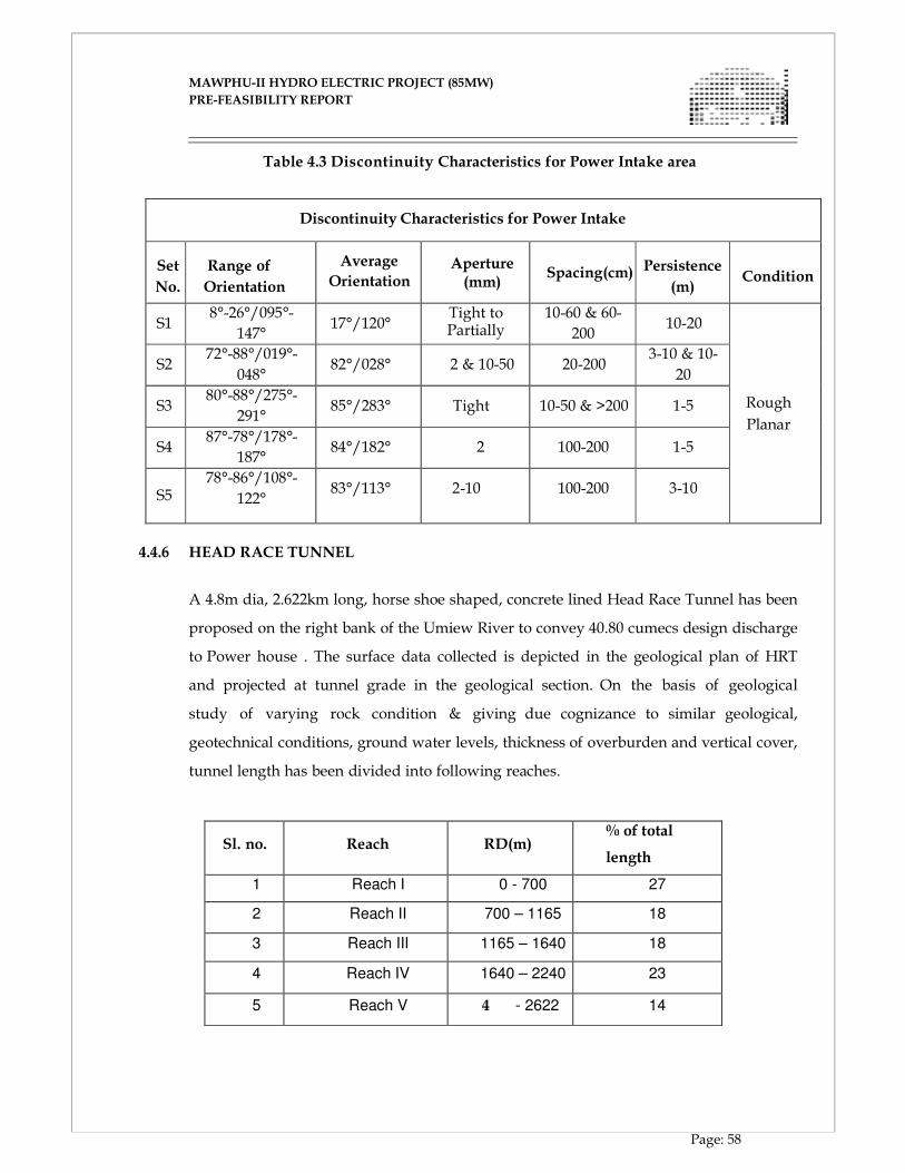
MAWPHU-II HYDRO ELECTRIC PROJECT (85MW)
MAWPHU-II HYDRO ELECTRIC PROJECT (85MW)
PRE-FEASIBILITY REPORT
Page: 58
Table 4.3 Discontinuity Characteristics for Power Intake area
Discontinuity Characteristics for Power Intake
Set
No.
Range of
Orientation
Average
Orientation Aperture (mm)
Spacing(cm)
Persistence
(m)
Condition
S1
8°-26°/095°-
147°
17°/120°
Tight to Partially
Open(<5m
10-60 & 60-
200
10-20
Rough
Planar
S2
72°-88°/019°-
048°
82°/028°
2 & 10-50
20-200
3-10 & 10-
20 S3
80°-88°/275°-
291°
85°/283°
Tight
10-50 & >200
1-5
S4
87°-78°/178°-
187°
84°/182°
2
100-200
1-5
S5
78°-86°/108°-
122°
83°/113°
2-10
100-200
3-10
4.4.6 HEAD RACE TUNNEL
A 4.8m dia, 2.622km long, horse shoe shaped, concrete lined Head Race Tunnel has been
proposed on the right bank of the Umiew River to convey 40.80 cumecs design discharge
to Power house . The surface data collected is depicted in the geological plan of HRT
and projected at tunnel grade in the geological section. On the basis of geological
study of varying rock condition & giving due cognizance to similar geological,
geotechnical conditions, ground water levels, thickness of overburden and vertical cover,
tunnel length has been divided into following reaches.
Sl. no.
Reach
RD(m) % of total
length
1 Reach I 0 - 700 27
2 Reach II 700 – 1165 18
3 Reach III 1165 – 1640 18
4 Reach IV 1640 – 2240 23
5 Reach V 4 - 2622 14
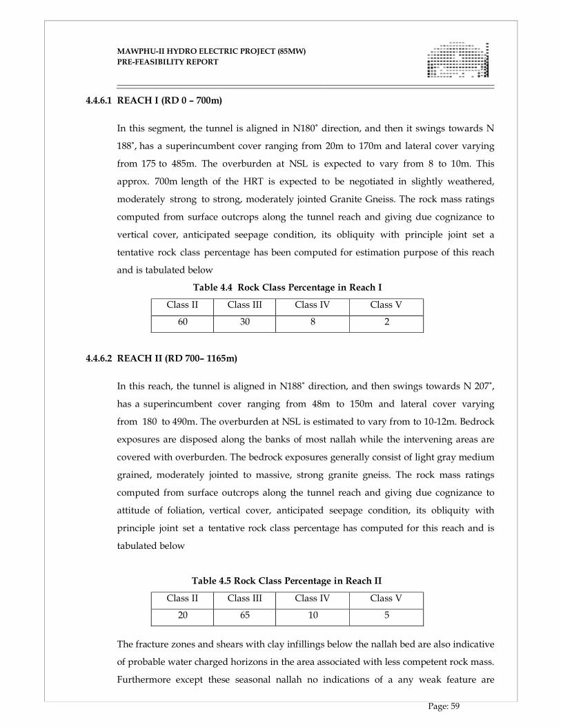
MAWPHU-II HYDRO ELECTRIC PROJECT (85MW)
MAWPHU-II HYDRO ELECTRIC PROJECT (85MW)
PRE-FEASIBILITY REPORT
Page: 59
4.4.6.1 REACH I (RD 0 – 700m)
In this segment, the tunnel is aligned in N180˚ direction, and then it swings towards N
188˚, has a superincumbent cover ranging from 20m to 170m and lateral cover varying
from 175 to 485m. The overburden at NSL is expected to vary from 8 to 10m. This
approx. 700m length of the HRT is expected to be negotiated in slightly weathered,
moderately strong to strong, moderately jointed Granite Gneiss. The rock mass ratings
computed from surface outcrops along the tunnel reach and giving due cognizance to
vertical cover, anticipated seepage condition, its obliquity with principle joint set a
tentative rock class percentage has been computed for estimation purpose of this reach
and is tabulated below
Table 4.4 Rock Class Percentage in Reach I
Class II Class III Class IV Class V
60 30 8 2
4.4.6.2 REACH II (RD 700– 1165m)
In this reach, the tunnel is aligned in N188˚ direction, and then swings towards N 207˚,
has a superincumbent cover ranging from 48m to 150m and lateral cover varying
from 180 to 490m. The overburden at NSL is estimated to vary from to 10-12m. Bedrock
exposures are disposed along the banks of most nallah while the intervening areas are
covered with overburden. The bedrock exposures generally consist of light gray medium
grained, moderately jointed to massive, strong granite gneiss. The rock mass ratings
computed from surface outcrops along the tunnel reach and giving due cognizance to
attitude of foliation, vertical cover, anticipated seepage condition, its obliquity with
principle joint set a tentative rock class percentage has computed for this reach and is
tabulated below
Table 4.5 Rock Class Percentage in Reach II
Class II Class III Class IV Class V
20 65 10 5
The fracture zones and shears with clay infillings below the nallah bed are also indicative
of probable water charged horizons in the area associated with less competent rock mass.
Furthermore except these seasonal nallah no indications of a any weak feature are
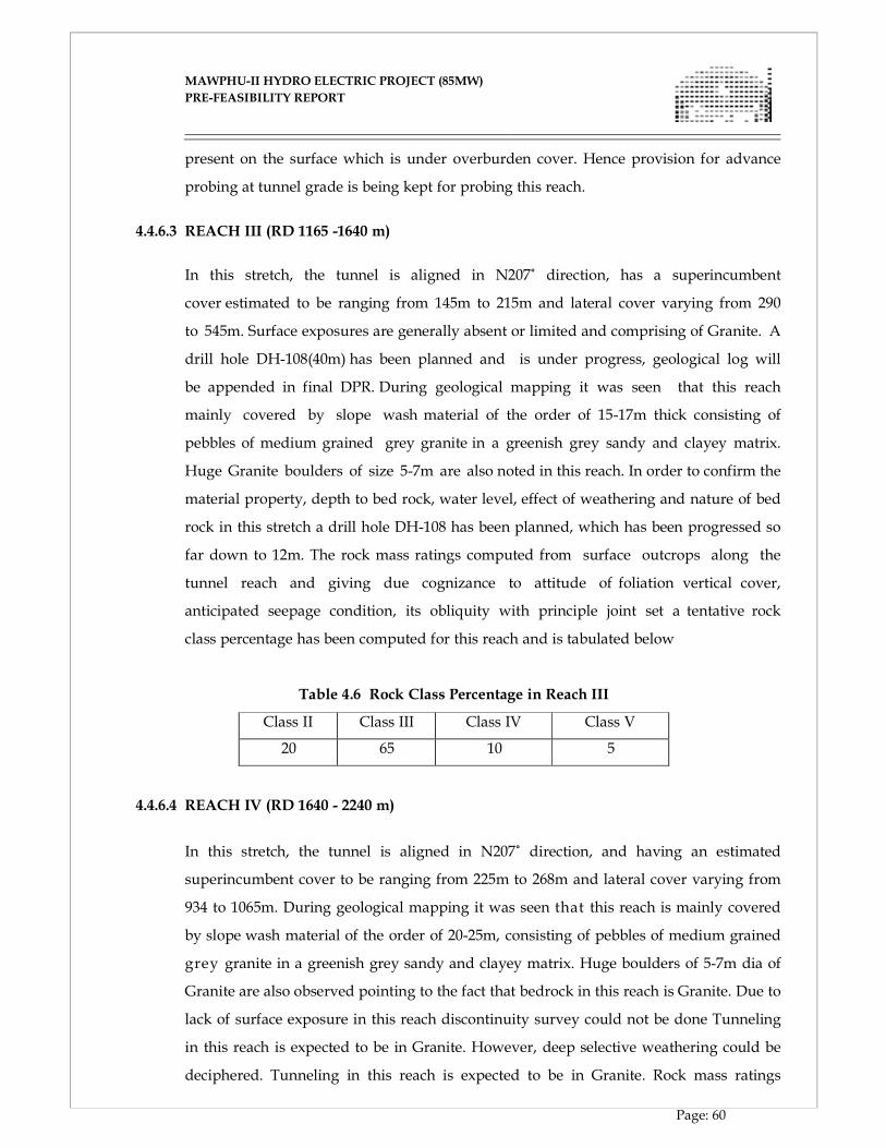
MAWPHU-II HYDRO ELECTRIC PROJECT (85MW)
MAWPHU-II HYDRO ELECTRIC PROJECT (85MW)
PRE-FEASIBILITY REPORT
Page: 60
present on the surface which is under overburden cover. Hence provision for advance
probing at tunnel grade is being kept for probing this reach.
4.4.6.3 REACH III (RD 1165 -1640 m)
In this stretch, the tunnel is aligned in N207˚ direction, has a superincumbent
cover estimated to be ranging from 145m to 215m and lateral cover varying from 290
to 545m. Surface exposures are generally absent or limited and comprising of Granite. A
drill hole DH-108(40m) has been planned and is under progress, geological log will
be appended in final DPR. During geological mapping it was seen that this reach
mainly covered by slope wash material of the order of 15-17m thick consisting of
pebbles of medium grained grey granite in a greenish grey sandy and clayey matrix.
Huge Granite boulders of size 5-7m are also noted in this reach. In order to confirm the
material property, depth to bed rock, water level, effect of weathering and nature of bed
rock in this stretch a drill hole DH-108 has been planned, which has been progressed so
far down to 12m. The rock mass ratings computed from surface outcrops along the
tunnel reach and giving due cognizance to attitude of foliation vertical cover,
anticipated seepage condition, its obliquity with principle joint set a tentative rock
class percentage has been computed for this reach and is tabulated below
Table 4.6 Rock Class Percentage in Reach III
Class II Class III Class IV Class V
20 65 10 5
4.4.6.4 REACH IV (RD 1640 - 2240 m)
In this stretch, the tunnel is aligned in N207˚ direction, and having an estimated
superincumbent cover to be ranging from 225m to 268m and lateral cover varying from
934 to 1065m. During geological mapping it was seen that this reach is mainly covered
by slope wash material of the order of 20-25m, consisting of pebbles of medium grained
grey granite in a greenish grey sandy and clayey matrix. Huge boulders of 5-7m dia of
Granite are also observed pointing to the fact that bedrock in this reach is Granite. Due to
lack of surface exposure in this reach discontinuity survey could not be done Tunneling
in this reach is expected to be in Granite. However, deep selective weathering could be
deciphered. Tunneling in this reach is expected to be in Granite. Rock mass ratings
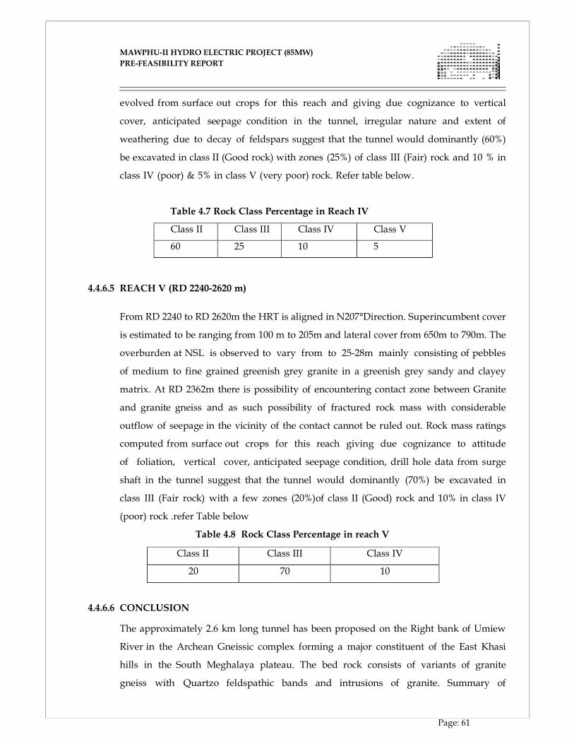
MAWPHU-II HYDRO ELECTRIC PROJECT (85MW)
MAWPHU-II HYDRO ELECTRIC PROJECT (85MW)
PRE-FEASIBILITY REPORT
Page: 61
evolved from surface out crops for this reach and giving due cognizance to vertical
cover, anticipated seepage condition in the tunnel, irregular nature and extent of
weathering due to decay of feldspars suggest that the tunnel would dominantly (60%)
be excavated in class II (Good rock) with zones (25%) of class III (Fair) rock and 10 % in
class IV (poor) & 5% in class V (very poor) rock. Refer table below.
Table 4.7 Rock Class Percentage in Reach IV
Class II Class III Class IV Class V
60 25 10 5
4.4.6.5 REACH V (RD 2240-2620 m)
From RD 2240 to RD 2620m the HRT is aligned in N207°Direction. Superincumbent cover
is estimated to be ranging from 100 m to 205m and lateral cover from 650m to 790m. The
overburden at NSL is observed to vary from to 25-28m mainly consisting of pebbles
of medium to fine grained greenish grey granite in a greenish grey sandy and clayey
matrix. At RD 2362m there is possibility of encountering contact zone between Granite
and granite gneiss and as such possibility of fractured rock mass with considerable
outflow of seepage in the vicinity of the contact cannot be ruled out. Rock mass ratings
computed from surface out crops for this reach giving due cognizance to attitude
of foliation, vertical cover, anticipated seepage condition, drill hole data from surge
shaft in the tunnel suggest that the tunnel would dominantly (70%) be excavated in
class III (Fair rock) with a few zones (20%)of class II (Good) rock and 10% in class IV
(poor) rock .refer Table below
Table 4.8 Rock Class Percentage in reach V
Class II Class III Class IV
20 70 10
4.4.6.6 CONCLUSION
The approximately 2.6 km long tunnel has been proposed on the Right bank of Umiew
River in the Archean Gneissic complex forming a major constituent of the East Khasi
hills in the South Meghalaya plateau. The bed rock consists of variants of granite
gneiss with Quartzo feldspathic bands and intrusions of granite. Summary of
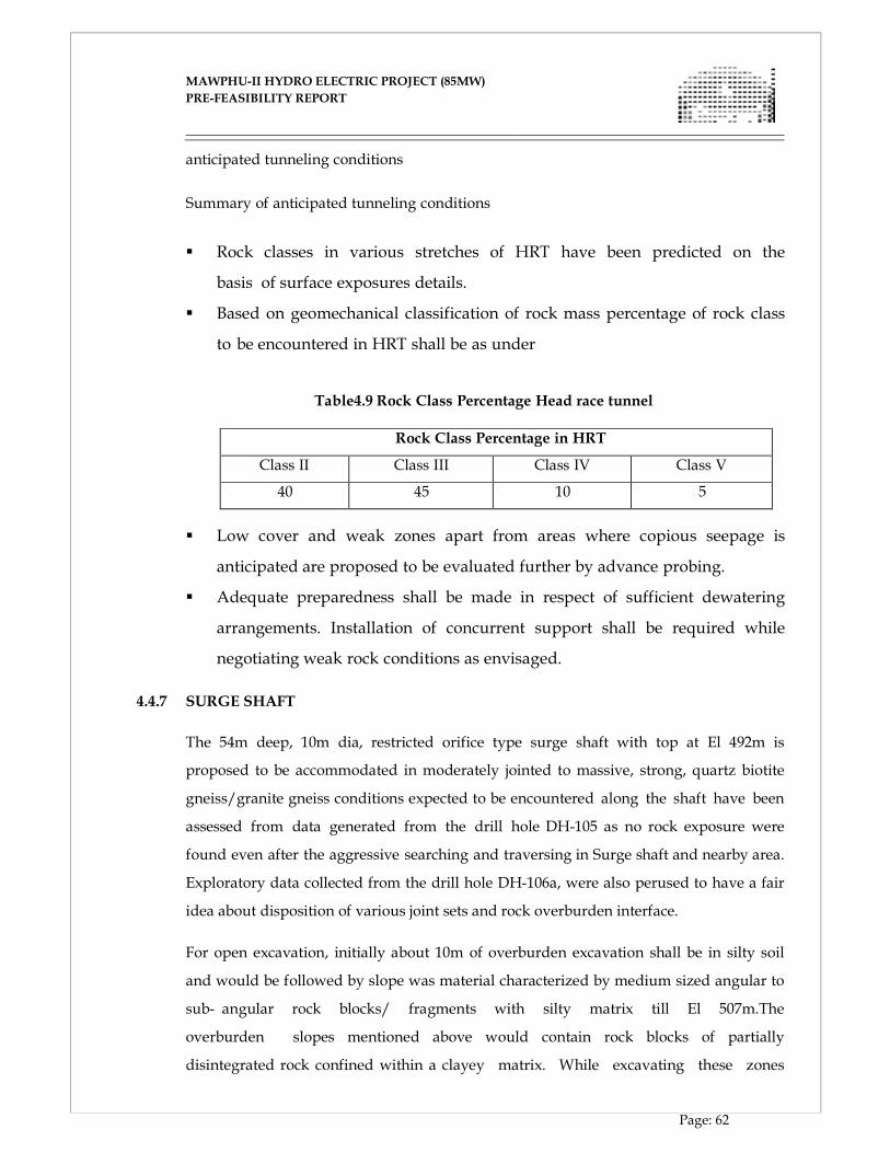
MAWPHU-II HYDRO ELECTRIC PROJECT (85MW)
MAWPHU-II HYDRO ELECTRIC PROJECT (85MW)
PRE-FEASIBILITY REPORT
Page: 62
anticipated tunneling conditions
Summary of anticipated tunneling conditions
� Rock classes in various stretches of HRT have been predicted on the
basis of surface exposures details.
� Based on geomechanical classification of rock mass percentage of rock class
to be encountered in HRT shall be as under
Table4.9 Rock Class Percentage Head race tunnel
Rock Class Percentage in HRT
Class II Class III Class IV Class V
40 45 10 5
� Low cover and weak zones apart from areas where copious seepage is
anticipated are proposed to be evaluated further by advance probing.
� Adequate preparedness shall be made in respect of sufficient dewatering
arrangements. Installation of concurrent support shall be required while
negotiating weak rock conditions as envisaged.
4.4.7 SURGE SHAFT
The 54m deep, 10m dia, restricted orifice type surge shaft with top at El 492m is
proposed to be accommodated in moderately jointed to massive, strong, quartz biotite
gneiss/granite gneiss conditions expected to be encountered along the shaft have been
assessed from data generated from the drill hole DH-105 as no rock exposure were
found even after the aggressive searching and traversing in Surge shaft and nearby area.
Exploratory data collected from the drill hole DH-106a, were also perused to have a fair
idea about disposition of various joint sets and rock overburden interface.
For open excavation, initially about 10m of overburden excavation shall be in silty soil
and would be followed by slope was material characterized by medium sized angular to
sub- angular rock blocks/ fragments with silty matrix till El 507m.The
overburden slopes mentioned above would contain rock blocks of partially
disintegrated rock confined within a clayey matrix. While excavating these zones
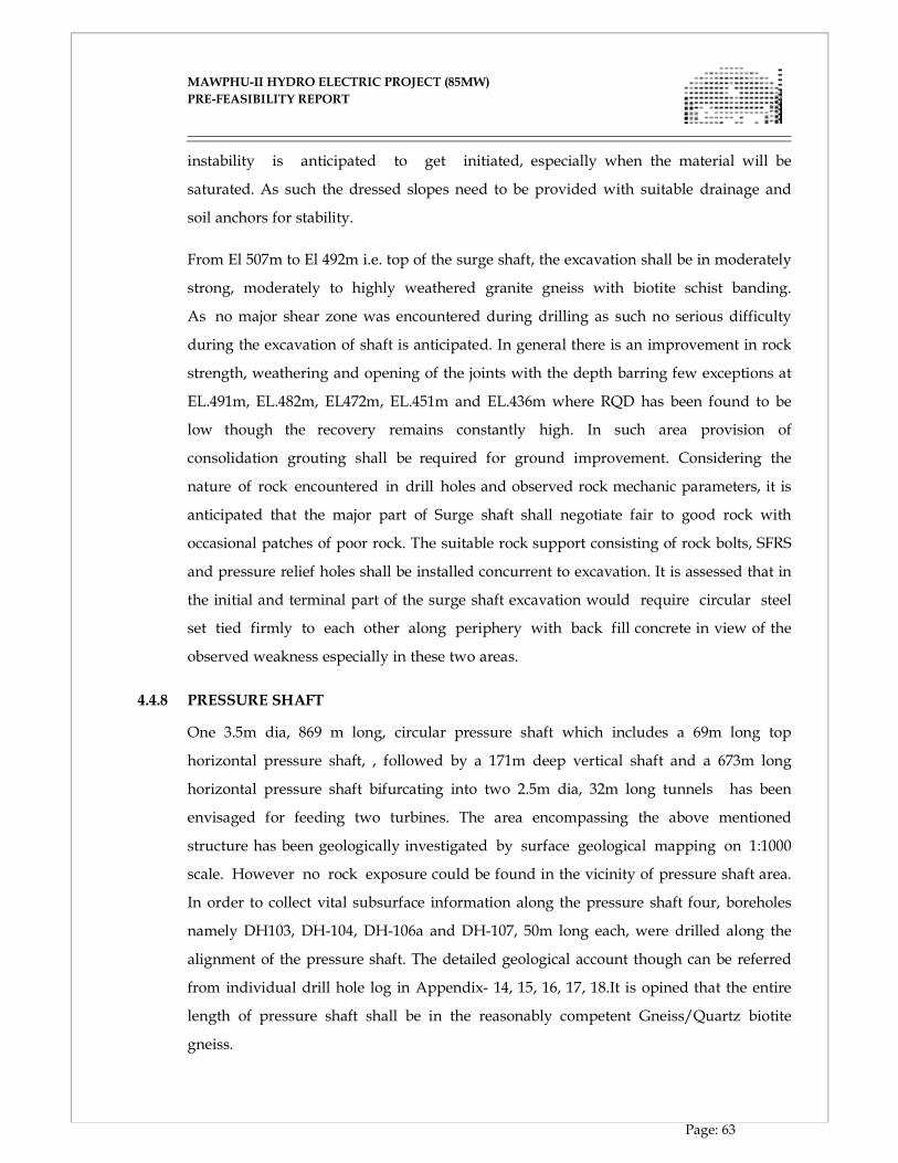
MAWPHU-II HYDRO ELECTRIC PROJECT (85MW)
MAWPHU-II HYDRO ELECTRIC PROJECT (85MW)
PRE-FEASIBILITY REPORT
Page: 63
instability is anticipated to get initiated, especially when the material will be
saturated. As such the dressed slopes need to be provided with suitable drainage and
soil anchors for stability.
From El 507m to El 492m i.e. top of the surge shaft, the excavation shall be in moderately
strong, moderately to highly weathered granite gneiss with biotite schist banding.
As no major shear zone was encountered during drilling as such no serious difficulty
during the excavation of shaft is anticipated. In general there is an improvement in rock
strength, weathering and opening of the joints with the depth barring few exceptions at
EL.491m, EL.482m, EL472m, EL.451m and EL.436m where RQD has been found to be
low though the recovery remains constantly high. In such area provision of
consolidation grouting shall be required for ground improvement. Considering the
nature of rock encountered in drill holes and observed rock mechanic parameters, it is
anticipated that the major part of Surge shaft shall negotiate fair to good rock with
occasional patches of poor rock. The suitable rock support consisting of rock bolts, SFRS
and pressure relief holes shall be installed concurrent to excavation. It is assessed that in
the initial and terminal part of the surge shaft excavation would require circular steel
set tied firmly to each other along periphery with back fill concrete in view of the
observed weakness especially in these two areas.
4.4.8 PRESSURE SHAFT
One 3.5m dia, 869 m long, circular pressure shaft which includes a 69m long top
horizontal pressure shaft, , followed by a 171m deep vertical shaft and a 673m long
horizontal pressure shaft bifurcating into two 2.5m dia, 32m long tunnels has been
envisaged for feeding two turbines. The area encompassing the above mentioned
structure has been geologically investigated by surface geological mapping on 1:1000
scale. However no rock exposure could be found in the vicinity of pressure shaft area.
In order to collect vital subsurface information along the pressure shaft four, boreholes
namely DH103, DH-104, DH-106a and DH-107, 50m long each, were drilled along the
alignment of the pressure shaft. The detailed geological account though can be referred
from individual drill hole log in Appendix- 14, 15, 16, 17, 18.It is opined that the entire
length of pressure shaft shall be in the reasonably competent Gneiss/Quartz biotite
gneiss.
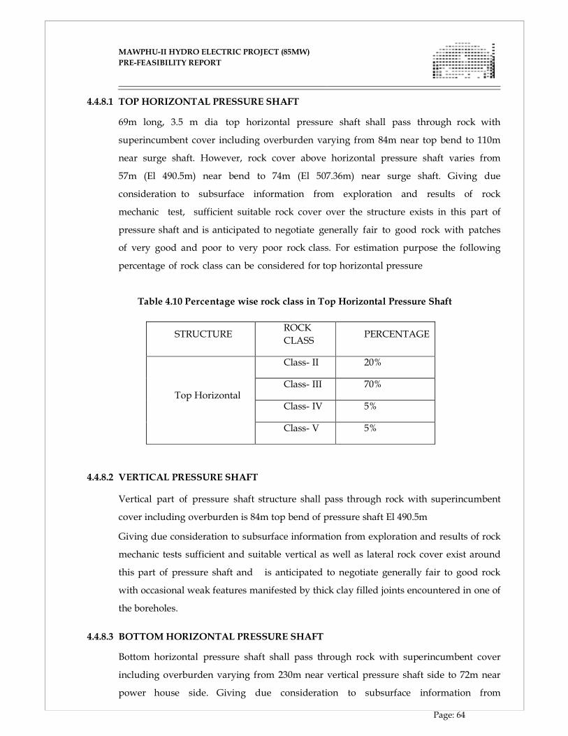
MAWPHU-II HYDRO ELECTRIC PROJECT (85MW)
MAWPHU-II HYDRO ELECTRIC PROJECT (85MW)
PRE-FEASIBILITY REPORT
Page: 64
4.4.8.1 TOP HORIZONTAL PRESSURE SHAFT
69m long, 3.5 m dia top horizontal pressure shaft shall pass through rock with
superincumbent cover including overburden varying from 84m near top bend to 110m
near surge shaft. However, rock cover above horizontal pressure shaft varies from
57m (El 490.5m) near bend to 74m (El 507.36m) near surge shaft. Giving due
consideration to subsurface information from exploration and results of rock
mechanic test, sufficient suitable rock cover over the structure exists in this part of
pressure shaft and is anticipated to negotiate generally fair to good rock with patches
of very good and poor to very poor rock class. For estimation purpose the following
percentage of rock class can be considered for top horizontal pressure
Table 4.10 Percentage wise rock class in Top Horizontal Pressure Shaft
STRUCTURE
ROCK
CLASS
PERCENTAGE
Top Horizontal
Class- II 20%
Class- III 70%
Class- IV 5%
Class- V 5%
4.4.8.2 VERTICAL PRESSURE SHAFT
Vertical part of pressure shaft structure shall pass through rock with superincumbent
cover including overburden is 84m top bend of pressure shaft El 490.5m
Giving due consideration to subsurface information from exploration and results of rock
mechanic tests sufficient and suitable vertical as well as lateral rock cover exist around
this part of pressure shaft and is anticipated to negotiate generally fair to good rock
with occasional weak features manifested by thick clay filled joints encountered in one of
the boreholes.
4.4.8.3 BOTTOM HORIZONTAL PRESSURE SHAFT
Bottom horizontal pressure shaft shall pass through rock with superincumbent cover
including overburden varying from 230m near vertical pressure shaft side to 72m near
power house side. Giving due consideration to subsurface information from
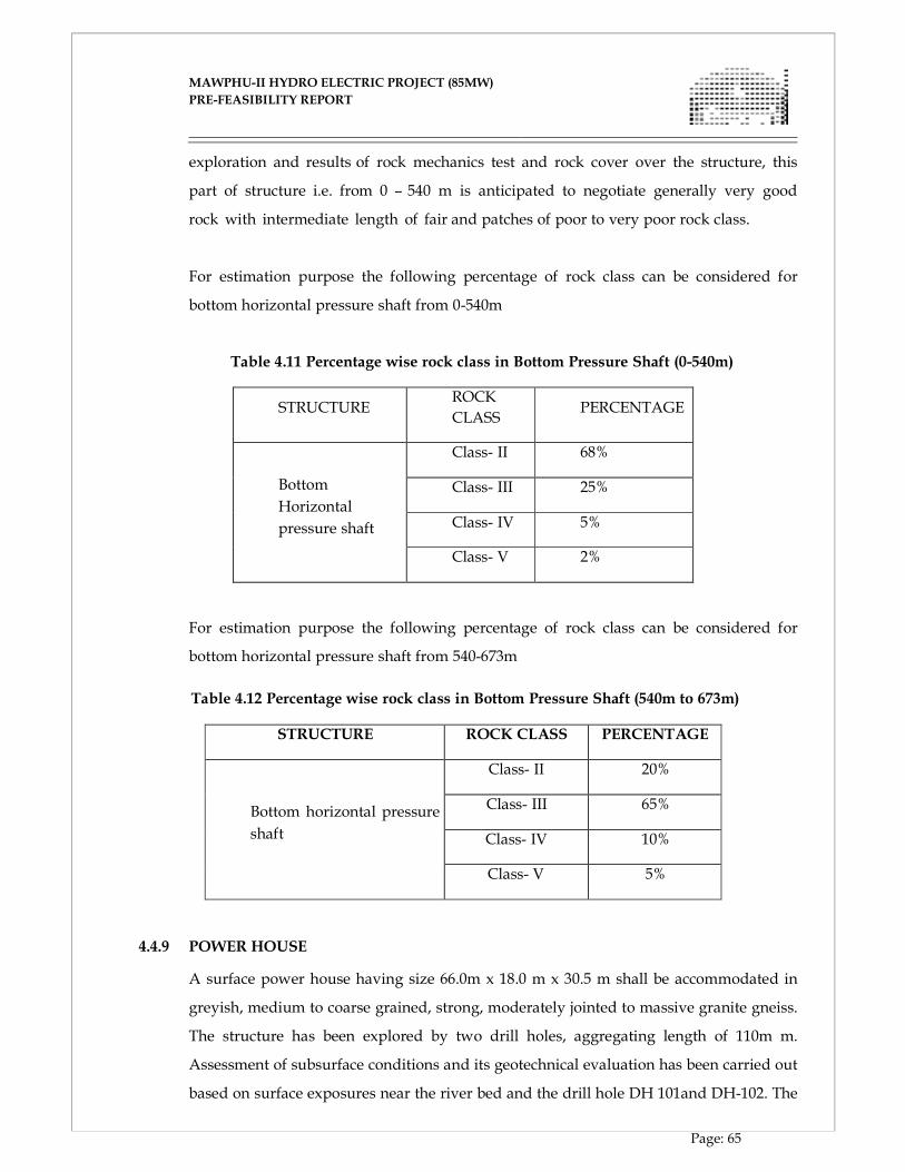
MAWPHU-II HYDRO ELECTRIC PROJECT (85MW)
MAWPHU-II HYDRO ELECTRIC PROJECT (85MW)
PRE-FEASIBILITY REPORT
Page: 65
exploration and results of rock mechanics test and rock cover over the structure, this
part of structure i.e. from 0 – 540 m is anticipated to negotiate generally very good
rock with intermediate length of fair and patches of poor to very poor rock class.
For estimation purpose the following percentage of rock class can be considered for
bottom horizontal pressure shaft from 0-540m
Table 4.11 Percentage wise rock class in Bottom Pressure Shaft (0-540m)
STRUCTURE
ROCK
CLASS
PERCENTAGE
Bottom
Horizontal
pressure shaft
Class- II 68%
Class- III 25%
Class- IV 5%
Class- V 2%
For estimation purpose the following percentage of rock class can be considered for
bottom horizontal pressure shaft from 540-673m
Table 4.12 Percentage wise rock class in Bottom Pressure Shaft (540m to 673m)
STRUCTURE ROCK CLASS PERCENTAGE
Bottom horizontal pressure
shaft
Class- II 20%
Class- III 65%
Class- IV 10%
Class- V 5%
4.4.9 POWER HOUSE
A surface power house having size 66.0m x 18.0 m x 30.5 m shall be accommodated in
greyish, medium to coarse grained, strong, moderately jointed to massive granite gneiss.
The structure has been explored by two drill holes, aggregating length of 110m m.
Assessment of subsurface conditions and its geotechnical evaluation has been carried out
based on surface exposures near the river bed and the drill hole DH 101and DH-102. The
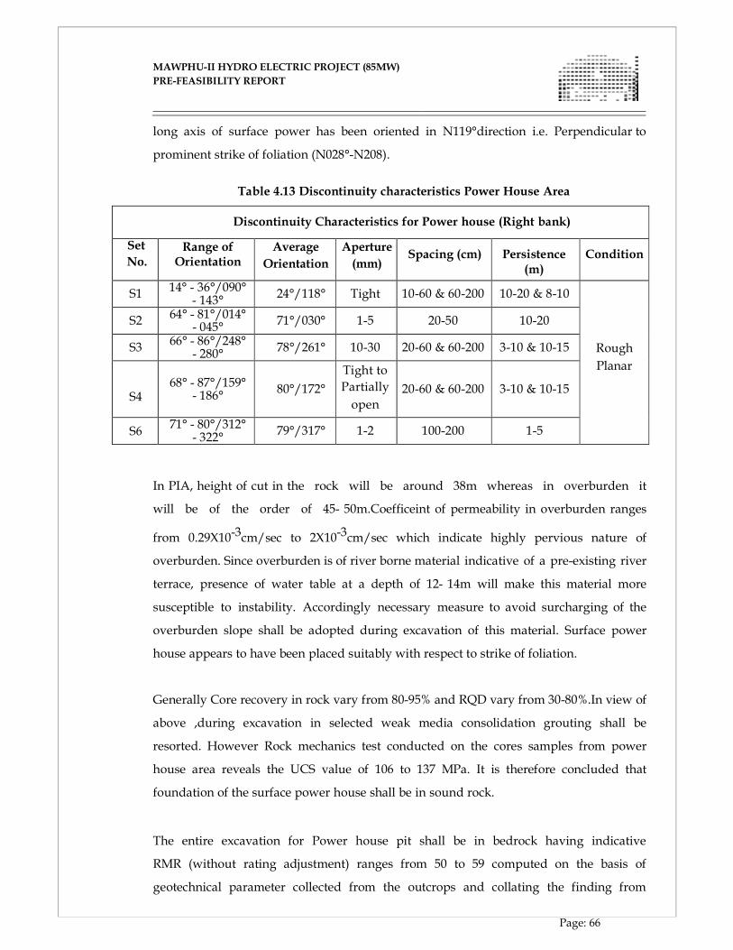
MAWPHU-II HYDRO ELECTRIC PROJECT (85MW)
MAWPHU-II HYDRO ELECTRIC PROJECT (85MW)
PRE-FEASIBILITY REPORT
Page: 66
long axis of surface power has been oriented in N119°direction i.e. Perpendicular to
prominent strike of foliation (N028°-N208).
Table 4.13 Discontinuity characteristics Power House Area
Discontinuity Characteristics for Power house (Right bank)
Set
No. Range of
Orientation Average
Orientation
Aperture
(mm)
Spacing (cm)
Persistence
(m)
Condition
S1 14° - 36°/090°
- 143° 24°/118° Tight 10-60 & 60-200 10-20 & 8-10
Rough
Planar
S2 64° - 81°/014°
- 045° 71°/030° 1-5 20-50 10-20
S3 66° - 86°/248°
- 280° 78°/261° 10-30 20-60 & 60-200 3-10 & 10-15
S4
68° - 87°/159° - 186°
80°/172°
Tight to
Partially
open 20-60 & 60-200 3-10 & 10-15
S6 71° - 80°/312°
- 322° 79°/317° 1-2 100-200 1-5
In PIA, height of cut in the rock will be around 38m whereas in overburden it
will be of the order of 45- 50m.Coefficeint of permeability in overburden ranges
from 0.29X10⁻³cm/sec to 2X10⁻³cm/sec which indicate highly pervious nature of
overburden. Since overburden is of river borne material indicative of a pre-existing river
terrace, presence of water table at a depth of 12- 14m will make this material more
susceptible to instability. Accordingly necessary measure to avoid surcharging of the
overburden slope shall be adopted during excavation of this material. Surface power
house appears to have been placed suitably with respect to strike of foliation.
Generally Core recovery in rock vary from 80-95% and RQD vary from 30-80%.In view of
above ,during excavation in selected weak media consolidation grouting shall be
resorted. However Rock mechanics test conducted on the cores samples from power
house area reveals the UCS value of 106 to 137 MPa. It is therefore concluded that
foundation of the surface power house shall be in sound rock.
The entire excavation for Power house pit shall be in bedrock having indicative
RMR (without rating adjustment) ranges from 50 to 59 computed on the basis of
geotechnical parameter collected from the outcrops and collating the finding from
MAWPHU-II HYDRO ELECTRIC PROJECT (85MW)
MAWPHU-II HYDRO ELECTRIC PROJECT (85MW)
PRE-FEASIBILITY REPORT
Page: 67
boreholes DH-101 and DH-102 in which bedrock was encountered at El 268.6m and
262.2m respectively.
4.4.10 TAIL RACE CHANNEL
In order to release of downstream discharge from Power House back to the river, a 23m
X 26m recovery bay and 35m long tail race channel aligned along N 230° having
width of about 8m with El 230m at river bed level has been provided.
The initial part at NSL exhibits consistent presence of overburden material characterized
by the presence of recent fluvial material constituted of sand gravel silt etc whereas
terminal stretch of TRC is seem to be occupied by outcrops of gneiss. Minimum
excavation level from a draft tube is El ± 219 m from where channel approaches
further through recovery bay with reverse gradient to meet the river at EL ± 230m. The
entire excavation for recovery bay and TRC shall be in bedrock having indicative RMR
(without rating adjustment) ranges from 50 To 59 computed on the basis of geotechnical
parameter collected from the outcrops and collating the finding from boreholes DH-101
and DH-102 in which bedrock was encountered at El 268.6m and 262.2m respectively.
In view of this it opined that tail race system including the recovery bay shall be on bed
rock constituted of slightly weathered strong to very strong, moderately jointed, grey
gneiss.
To minimize the effect of some of these adversely oriented joints on excavation
particularly on the western wall, systematic rock support with rock bolts of 25mm Ø
4 to 6m long with spacing of 2m center to center, adequate thickness of SFRS,
and pressure relief arrangement shall be required to installed concurrent to the
excavation. Furthermore, provision of consolidation grouting shall be made as ground
improvement measure.
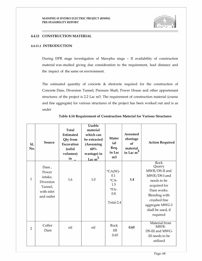
MAWPHU-II HYDRO ELECTRIC PROJECT (85MW)
MAWPHU-II HYDRO ELECTRIC PROJECT (85MW)
PRE-FEASIBILITY REPORT
Page: 68
4.4.11 CONSTRUCTION MATERIAL
4.4.11.1 INTRODUCTION
During DPR stage investigation of Mawphu stage – II availability of construction
material was studied giving due consideration to the requirement, lead distance and
the impact of the same on environment.
The estimated quantity of concrete & shotcrete required for the construction of
Concrete Dam, Diversion Tunnel, Pressure Shaft, Power House and other appurtenant
structures of the project is 2.2 Lac m3. The requirement of construction material (coarse
and fine aggregate) for various structures of the project has been worked out and is as
under
Table 4.14 Requirement of Construction Material for Various Structures
Sl. No.
Source
Total
Estimated
Qty from
Excavation
(solid
volumes)
in
Lac m3
Usable
material
which can
be extracted
(Assuming
60%
wastage) in
Lac m3
Mater
ial
Req.
in Lac
m3
Assumed
shortage
of
material
in Lac m3
Action Required
1
Dam ,
Power
intake,
Diversion
Tunnel,
with inlet
and outlet
1.6
1.0
*CA(W)-0.1
*CA-1.5
*FA-0.8
Total-2.4
1.4
Rock Quarry
MWR/DS-II and
MWR/DS-I and
needs to be
acquired for
Dam works.
Blending with
crushed fine
aggregate MWG-I
shall be used, if
required
2
Coffer
Dam
nil
nil
Rock
fill
0.65
0.65
Material from MWR-
DS-III and MWG-
III needs to be
utilized
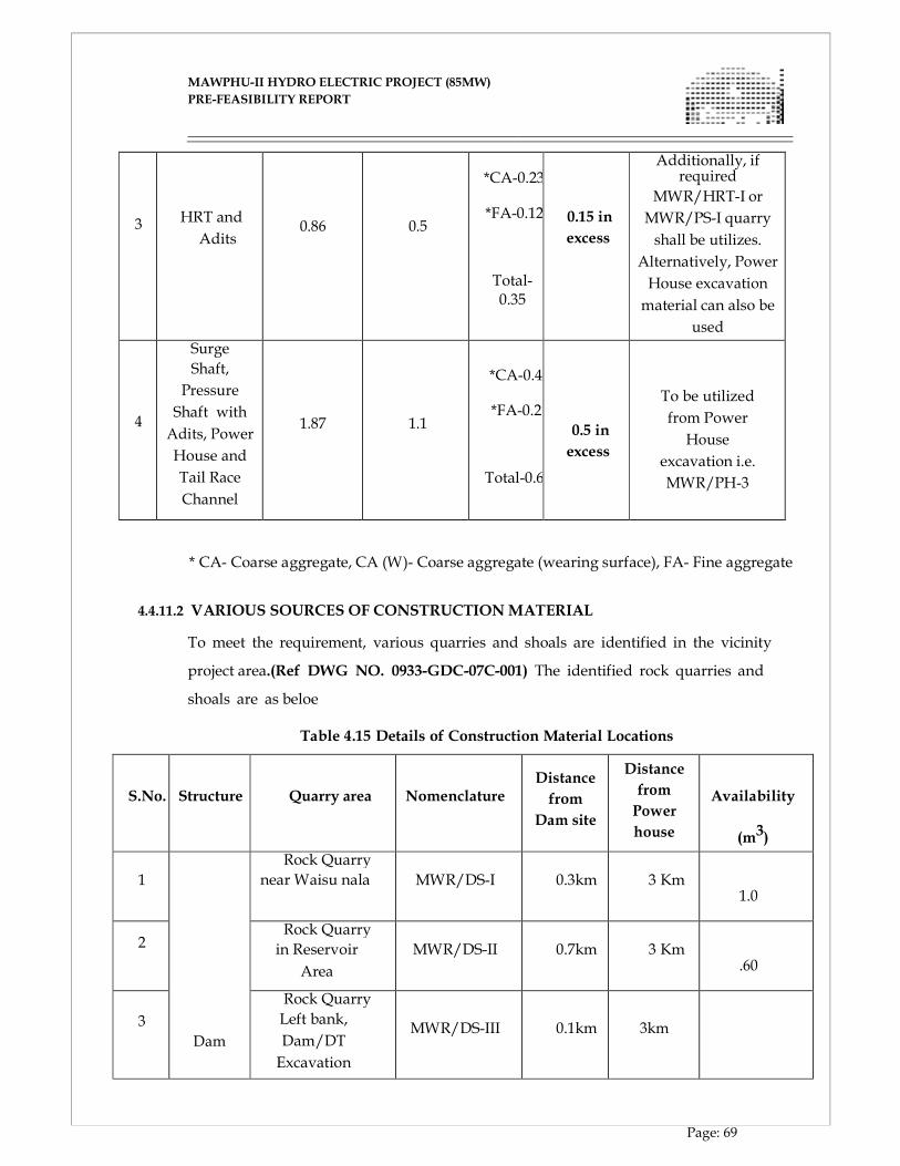
MAWPHU-II HYDRO ELECTRIC PROJECT (85MW)
MAWPHU-II HYDRO ELECTRIC PROJECT (85MW)
PRE-FEASIBILITY REPORT
Page: 69
3
HRT and
Adits
0.86
0.5
*CA-0.23
*FA-0.12
Total-0.35
0.15 in
excess
Additionally, if required
MWR/HRT-I or
MWR/PS-I quarry
shall be utilizes.
Alternatively, Power
House excavation
material can also be
used
4
Surge
Shaft,
Pressure
Shaft with
Adits, Power
House and
Tail Race
Channel
1.87
1.1
*CA-0.4
*FA-0.2
Total-0.6
0.5 in
excess
To be utilized
from Power
House
excavation i.e.
MWR/PH-3
* CA- Coarse aggregate, CA (W)- Coarse aggregate (wearing surface), FA- Fine aggregate
4.4.11.2 VARIOUS SOURCES OF CONSTRUCTION MATERIAL
To meet the requirement, various quarries and shoals are identified in the vicinity
project area.(Ref DWG NO. 0933-GDC-07C-001) The identified rock quarries and
shoals are as beloe
Table 4.15 Details of Construction Material Locations
S.No.
Structure
Quarry area
Nomenclature
Distance
from
Dam site
Distance
from
Power
house
Availability
(m3)
1
Dam
Rock Quarry
near Waisu nala
MWR/DS-I 0.3km
3 Km
1.0
2
Rock Quarry
in Reservoir
Area
MWR/DS-II
0.7km
3 Km
.60
3
Rock Quarry
Left bank,
Dam/DT
Excavation
MWR/DS-III
0.1km
3km
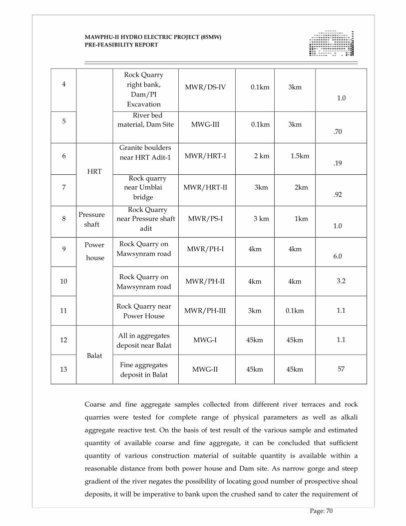
MAWPHU-II HYDRO ELECTRIC PROJECT (85MW)
MAWPHU-II HYDRO ELECTRIC PROJECT (85MW)
PRE-FEASIBILITY REPORT
Page: 70
4
Rock Quarry
right bank,
Dam/PI
Excavation
MWR/DS-IV
0.1km
3km
1.0
5
River bed
material, Dam Site
MWG-III 0.1km
3km
.70
6
HRT
Granite boulders
near HRT Adit-1
MWR/HRT-I
2 km
1.5km
.19
7
Rock quarry
near Umblai
bridge
MWR/HRT-II
3km
2km
.92
8
Pressure
shaft
Rock Quarry
near Pressure shaft
adit
MWR/PS-I
3 km
1km
1.0
9
Power
house
Rock Quarry on
Mawsynram road
MWR/PH-I
4km
4km
6.0
10 Rock Quarry on
Mawsynram road MWR/PH-II 4km 4km 3.2
11 Rock Quarry near
Power House MWR/PH-III 3km 0.1km 1.1
12
Balat
All in aggregates
deposit near Balat MWG-I 45km 45km 1.1
13 Fine aggregates
deposit in Balat MWG-II 45km 45km 57
Coarse and fine aggregate samples collected from different river terraces and rock
quarries were tested for complete range of physical parameters as well as alkali
aggregate reactive test. On the basis of test result of the various sample and estimated
quantity of available coarse and fine aggregate, it can be concluded that sufficient
quantity of various construction material of suitable quantity is available within a
reasonable distance from both power house and Dam site. As narrow gorge and steep
gradient of the river negates the possibility of locating good number of prospective shoal
deposits, it will be imperative to bank upon the crushed sand to cater the requirement of
MAWPHU-II HYDRO ELECTRIC PROJECT (85MW)
MAWPHU-II HYDRO ELECTRIC PROJECT (85MW)
PRE-FEASIBILITY REPORT
Page: 71
major part of fine aggregate. However, if need be, to maintain the proper grading of
fine aggregate blending of river sand of appropriate selected grain size range from
Balat Shoal deposit can be made. To enlarge the data base beyond BOQ for
construction material survey few more samples from the dam area have also been
collected and shall be perused once the report is received. The samples except
MWR/HRT-II, collected and tested from the entire project area in this campaign, confirm
its suitability as both wearing and non-wearing surfaces and also in regards to their alkali
aggregate reactivity status being tested innocuous. However, MWR/ HRT-II collected
from granitic area are observed to be marginally deficient with respect to impart
value, Loa Angeles abrasion value, crushing value i.e. 27.61, 38.6 and 29.4 respectively.
In view of this, to take care of in homogeneity of the granitic material, it is proposed to
collect more samples during construction or in pre-construction stage from the granitic
area to decipher its possible utility as wearing surface, through segregation once the
report becomes available
A serious effort was made to assess the suitability of the excavated material anticipated
to be generated during construction of the project. This would not only have a positive
impact in the project cost but also shall ensure minimum adverse impact on
environment.
CHAPTER - V
HYDROLOGY
MAWPHU-II HYDRO ELECTRIC PROJECT (85MW)
MAWPHU-II HYDRO ELECTRIC PROJECT (85MW)
PRE-FEASIBILITY REPORT
Page: 72
CHAPTER - V
HYDROLOGY
5.1. GENERAL
The great Himalayan mountain range with its permanently snow covered mountain
peaks; the mighty Brahmaputra and its perennial tributaries, flowing in loops and
bends and the south-east monsoon causing highest rainfall in Meghalaya, are the
natural parameters responsible for North-East India to emerge as a boon for
hydro-electric power generation. Central Electricity Authority (CEA), in their
publication “Hydro-Electric Power Potential of India-1988” estimated the optimum
installable capacity of Brahmaputra basin as about 66,065 MW, out of which only
about 2% have been harnessed so far. Due to increase in population,
urbanization and industrialization, the power demand has increased considerably.
To meet the increased power demand, Central Government and various State
Governments of the region are making all out efforts to develop the hydro-power
potential of the region.
5.2. THE PROJECT
Mawphu-II Hydroelectric Project is planned in East Khasi Hills District in the State of
Meghalaya on the River Umiew, a tributary of the River Surma, which itself is
one of the major left bank tributaries of Brahmaputra. The project envisages the
construction of a concrete gravity dam of 51 m high (from the deepest foundation
level) across river Umiew to utilize a gross head of 238 m for hydro power generation.
The proposed dam is located near Mawphu village (located on the left bank), about
8 km away from Mawsynram and 2 km away from Thieddieng village (located
on the right bank). The project is located at latitude 25° 18’ 32’’N and longitude 91°
38’19”E. The catchment area up to the dam site is 308 sq. km and the entire catchment
is rain –fed.
5.3. THE RIVER SYSTEM AND BASIN CHARACTERISTICS
The Umiew River (known as Umlam in initial reaches) originates as a small
MAWPHU-II HYDRO ELECTRIC PROJECT (85MW)
MAWPHU-II HYDRO ELECTRIC PROJECT (85MW)
PRE-FEASIBILITY REPORT
Page: 73
stream at an elevation of about 1940 m in East Khasi hills of Meghalaya. Initially the
River flows in southern direction for about 4 km with a slope of about 1 in 30. For
the next 6 km, it flows in south- eastern direction with relatively flat gradient of 1
in 225. Few small Streams and Nallas join in this stretch enriching its discharge. It
then turns westwards and continues its path for further 12 km before it turns in south
west direction. The 7 km journey in south west direction up to Mawphlang is
quite steep with a gradient of about 1 in 12. At Mawphlang the river is barricaded by
a dam to form a reservoir for a scheme project known as Greater Shillong Water
Supply Scheme (GSWSS). Fulfilling the drinking water need of Shillong is the
primary objective of the scheme.
Main tributaries of Umiew up to GSWSS are Umjilling, Umtongsieum and Wah
Umsaw. After crossing this scheme project, river extends its journey for about 13 km
in a gradient of about 1 in 175. Nallas like Umjaut, Umduna join in its right bank and
Umlong joins in its left bank. The discharges of these nallas increase the potential of
the river to develop the proposed Mawphu Stage I (90 MW) Hydro Power Project.
Mawphu-II (85 MW) Project lies further 13 km downstream of Mawphu Stage
I Project with additional contributions from Umjngut & Umkynrem nallas,
which join in the right bank. The total length of the river up to the project site is 54.54
km. Further the river flows towards the south below the confluence along the southern
slopes of Khasi Hills and enters Bangladesh beyond Shella in Indo-Bangladesh
border and joins the River Surma. Finally the River joins Brahmaputra and in turn
flows to Bay of Bengal via Sundarbans Delta.
The basin is bounded by Mawsynram in west, Shillong in North and Cherrapunji in
east and in fact world’s highest annual rainfall occurs at Cherrapunji and
Mawsynram. The slopes of the basin are covered with dense rainforests of
coniferous and deciduous trees with a number of small tribal villages in between.
The predominant land use pattern in the catchment area is forest of the type “Tropical
Moist Deciduous”. Very small area is under agricultural use including wet rice
cultivation in the intercept valleys.
MAWPHU-II HYDRO ELECTRIC PROJECT (85MW)
MAWPHU-II HYDRO ELECTRIC PROJECT (85MW)
PRE-FEASIBILITY REPORT
Page: 74
5.4. THE CATCHMENT The catchment up to the dam site could be covered by Survey of India Topo Sheet
nos. 78 O/10, 78 O/11, 78 O/14, 78 O/15. With the help of remote sensed satellite
images and also with the help of Arc GIS software, the catchment boundary has
been marked. The names of the nallas / tributaries of the Umiew River have been
extracted from the Topo sheets as well as from Google Earth to prepare the final
catchment area plan. The catchment area up to dam site has been worked out as 308
sq. km. The catchment lies between latitude 25°18’08”N to 25°32’50”N and Longitude
91° 35‘15”E and 91°55’30”E. Catchment area plan showing the location of gauge,
discharge and rain gauge station is given in Figure 5.1.
MAWPHU-II HYDRO ELECTRIC PROJECT (85MW)
MAWPHU-II HYDRO ELECTRIC PROJECT (85MW)
PRE-FEASIBILITY REPORT
Page: 75
308
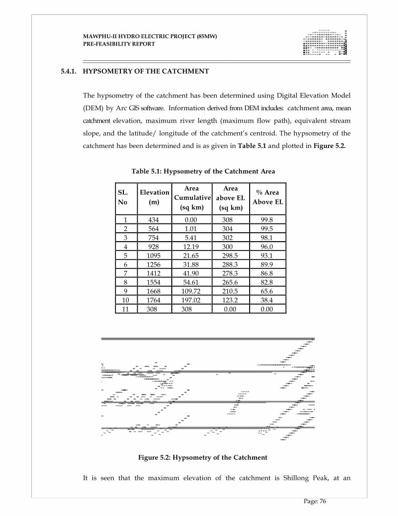
MAWPHU-II HYDRO ELECTRIC PROJECT (85MW)
MAWPHU-II HYDRO ELECTRIC PROJECT (85MW)
PRE-FEASIBILITY REPORT
Page: 76
5.4.1. HYPSOMETRY OF THE CATCHMENT
The hypsometry of the catchment has been determined using Digital Elevation Model
(DEM) by Arc GIS software. Information derived from DEM includes: catchment area, mean
catchment elevation, maximum river length (maximum flow path), equivalent stream
slope, and the latitude/ longitude of the catchment’s centroid. The hypsometry of the
catchment has been determined and is as given in Table 5.1 and plotted in Figure 5.2.
Table 5.1: Hypsometry of the Catchment Area
SL.
No
Elevation
(m)
Area
Cumulative
(sq km)
Area
above EL
(sq km)
% Area
Above EL
1 434 0.00 308 99.8
2 564 1.01 304 99.5
3 754 5.41 302 98.1
4 928 12.19 300 96.0
5 1095 21.65 298.5 93.1
6 1256 31.88 288.3 89.9
7 1412 41.90 278.3 86.8
8 1554 54.61 265.6 82.8
9 1668 109.72 210.5 65.6
10 1764 197.02 123.2 38.4
11 308 308 0.00 0.00
Figure 5.2: Hypsometry of the Catchment
It is seen that the maximum elevation of the catchment is Shillong Peak, at an
MAWPHU-II HYDRO ELECTRIC PROJECT (85MW)
MAWPHU-II HYDRO ELECTRIC PROJECT (85MW)
PRE-FEASIBILITY REPORT
Page: 77
elevation of about 1963 m, which indicates that the entire catchment is rain – fed.
Catchment area above 1500 m elevation is about 84 %.
5.4.2. ESTIMATION OF MEAN CATCHMENT ELEVATION
From the hypsometric data of the catchment, mean elevation of the catchment
has been worked out and the computations are given below in Table 5.2.
Table 5.2: Mean Catchment Elevation
Mean elevation of the catchment thus works out to 1354.4 m.
5.4.3. EQUIVALENT SLOPE
For determining the equivalent slope of River Umiew up to the dam site, the river
has been divided in to a number of segments. The computations for the equivalent
slope of the river are given in Table 5.3.
S.
No
Elevation
Range (m)
Mean
Elevation
(m)
Cumulative
Area (sq km)
Incremental
Area (sq km)
Mean Elevation
X Incremental
Area
1 434 – 564 499 1.0125 1.0125 505.2
2 564 – 754 659 5.4108 4.3983 2898.5
3 754 – 928 841 12.1905 6.7797 5701.7
4 928 – 1095 1011.5 21.6513 9.4608 9569.6
5 1095 - 1256 1175.5 31.8816 10.2303 12025.7
6 1256 - 1412 1334 41.9013 10.0197 13366.3
7 1412 - 1554 1483 54.6102 12.7089 18847.3
8 1554 - 1668 1611 109.7226 55.1124 88786.1
9 1668 - 1764 1716 197.0163 87.2937 149796.0
10 1764 - 1963 1042.1 308 110.9837 115656.1 Sum 308.0 417152.5 Mean Elevation 1354.4
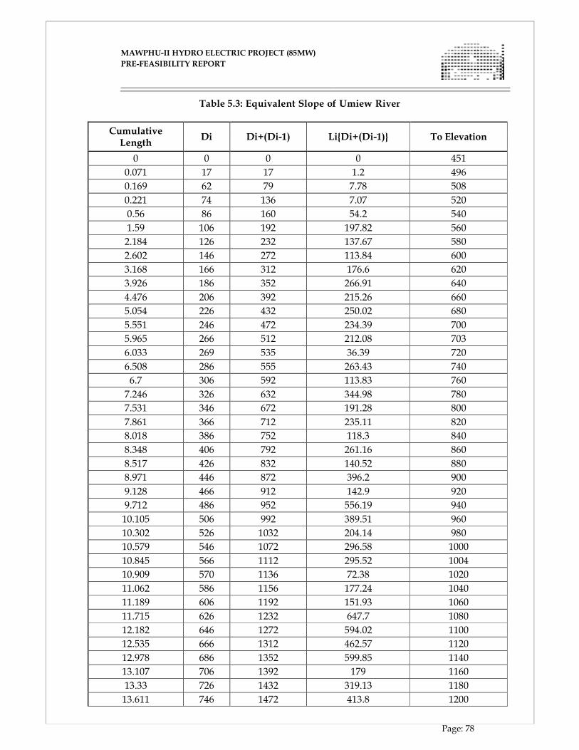
MAWPHU-II HYDRO ELECTRIC PROJECT (85MW)
MAWPHU-II HYDRO ELECTRIC PROJECT (85MW)
PRE-FEASIBILITY REPORT
Page: 78
Table 5.3: Equivalent Slope of Umiew River
Cumulative Length
Di Di+(Di-1) Li{Di+(Di-1)} To Elevation
0 0 0 0 451
0.071 17 17 1.2 496
0.169 62 79 7.78 508
0.221 74 136 7.07 520
0.56 86 160 54.2 540
1.59 106 192 197.82 560
2.184 126 232 137.67 580
2.602 146 272 113.84 600
3.168 166 312 176.6 620
3.926 186 352 266.91 640
4.476 206 392 215.26 660
5.054 226 432 250.02 680
5.551 246 472 234.39 700
5.965 266 512 212.08 703
6.033 269 535 36.39 720
6.508 286 555 263.43 740
6.7 306 592 113.83 760
7.246 326 632 344.98 780
7.531 346 672 191.28 800
7.861 366 712 235.11 820
8.018 386 752 118.3 840
8.348 406 792 261.16 860
8.517 426 832 140.52 880
8.971 446 872 396.2 900
9.128 466 912 142.9 920
9.712 486 952 556.19 940
10.105 506 992 389.51 960
10.302 526 1032 204.14 980
10.579 546 1072 296.58 1000
10.845 566 1112 295.52 1004
10.909 570 1136 72.38 1020
11.062 586 1156 177.24 1040
11.189 606 1192 151.93 1060
11.715 626 1232 647.7 1080
12.182 646 1272 594.02 1100
12.535 666 1312 462.57 1120
12.978 686 1352 599.85 1140
13.107 706 1392 179 1160
13.33 726 1432 319.13 1180
13.611 746 1472 413.8 1200
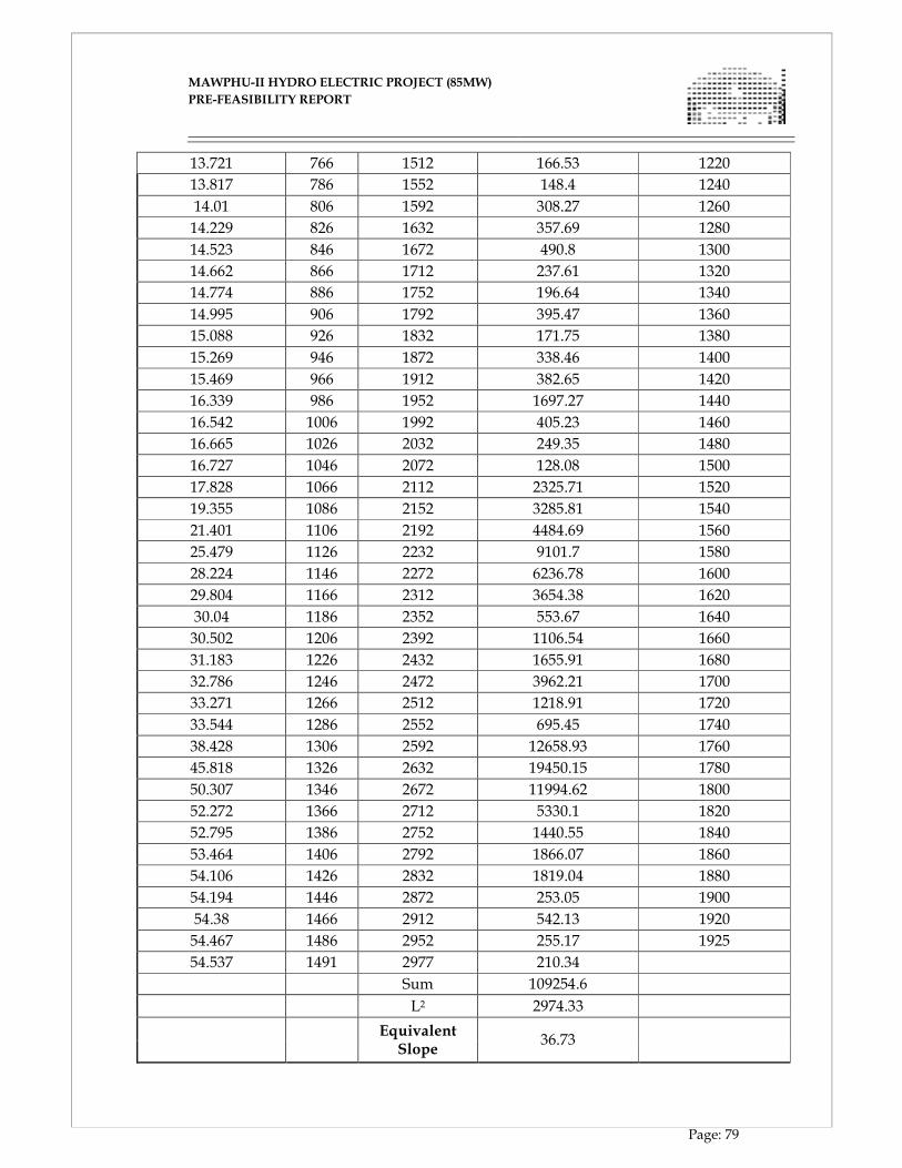
MAWPHU-II HYDRO ELECTRIC PROJECT (85MW)
MAWPHU-II HYDRO ELECTRIC PROJECT (85MW)
PRE-FEASIBILITY REPORT
Page: 79
13.721 766 1512 166.53 1220
13.817 786 1552 148.4 1240
14.01 806 1592 308.27 1260
14.229 826 1632 357.69 1280
14.523 846 1672 490.8 1300
14.662 866 1712 237.61 1320
14.774 886 1752 196.64 1340
14.995 906 1792 395.47 1360
15.088 926 1832 171.75 1380
15.269 946 1872 338.46 1400
15.469 966 1912 382.65 1420
16.339 986 1952 1697.27 1440
16.542 1006 1992 405.23 1460
16.665 1026 2032 249.35 1480
16.727 1046 2072 128.08 1500
17.828 1066 2112 2325.71 1520
19.355 1086 2152 3285.81 1540
21.401 1106 2192 4484.69 1560
25.479 1126 2232 9101.7 1580
28.224 1146 2272 6236.78 1600
29.804 1166 2312 3654.38 1620
30.04 1186 2352 553.67 1640
30.502 1206 2392 1106.54 1660
31.183 1226 2432 1655.91 1680
32.786 1246 2472 3962.21 1700
33.271 1266 2512 1218.91 1720
33.544 1286 2552 695.45 1740
38.428 1306 2592 12658.93 1760
45.818 1326 2632 19450.15 1780
50.307 1346 2672 11994.62 1800
52.272 1366 2712 5330.1 1820
52.795 1386 2752 1440.55 1840
53.464 1406 2792 1866.07 1860
54.106 1426 2832 1819.04 1880
54.194 1446 2872 253.05 1900
54.38 1466 2912 542.13 1920
54.467 1486 2952 255.17 1925
54.537 1491 2977 210.34
Sum 109254.6
L2 2974.33
Equivalent
Slope 36.73
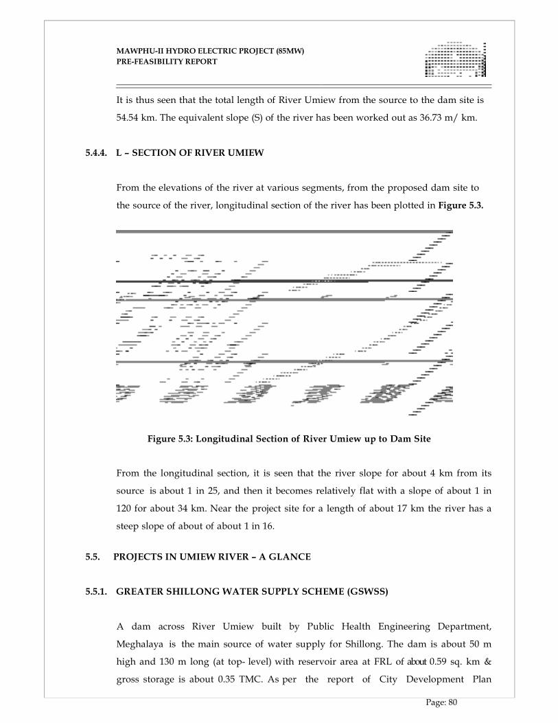
MAWPHU-II HYDRO ELECTRIC PROJECT (85MW)
MAWPHU-II HYDRO ELECTRIC PROJECT (85MW)
PRE-FEASIBILITY REPORT
Page: 80
It is thus seen that the total length of River Umiew from the source to the dam site is
54.54 km. The equivalent slope (S) of the river has been worked out as 36.73 m/ km.
5.4.4. L – SECTION OF RIVER UMIEW
From the elevations of the river at various segments, from the proposed dam site to
the source of the river, longitudinal section of the river has been plotted in Figure 5.3.
Figure 5.3: Longitudinal Section of River Umiew up to Dam Site
From the longitudinal section, it is seen that the river slope for about 4 km from its
source is about 1 in 25, and then it becomes relatively flat with a slope of about 1 in
120 for about 34 km. Near the project site for a length of about 17 km the river has a
steep slope of about of about 1 in 16.
5.5. PROJECTS IN UMIEW RIVER – A GLANCE
5.5.1. GREATER SHILLONG WATER SUPPLY SCHEME (GSWSS)
A dam across River Umiew built by Public Health Engineering Department,
Meghalaya is the main source of water supply for Shillong. The dam is about 50 m
high and 130 m long (at top- level) with reservoir area at FRL of about 0.59 sq. km &
gross storage is about 0.35 TMC. As per the report of City Development Plan
MAWPHU-II HYDRO ELECTRIC PROJECT (85MW)
MAWPHU-II HYDRO ELECTRIC PROJECT (85MW)
PRE-FEASIBILITY REPORT
Page: 81
prepared by Jawaharlal Nehru National Urban Renewal Mission (JNNURM) by
Feb 2007, the quantity of water generated from GSWSS is 11.3 mld (0.5 cumecs).
5.5.2. MAWPHU STAGE I HEP (90 MW)
As stated in the old PFR of Mawphu II, Under the 50000 MW hydro Power
Initiative, Pre- Feasibility Reports for the following projects on Umiew River basin of
Meghalaya were prepared by WAPCOS:
Umjaut HEP (69 MW) : FRL- 1346 m & TWL – 952 m
Umduna HEP (57 MW) : FRL – 950 m & TWL – 687 m
Mawphu HEP(120 MW) : FRL – 684 m & TWL – 210.5 m
In May 2005, Govt. Of Meghalaya authorized NEEPCO to prepare DPR of Mawphu HEP
(120 MW). During survey and investigation process of the project, NEEPCO observed
some of the project parameters as cited in its PFR were found to have some
discrepancy with actual site parameters. Hence, NEEPCO went ahead for the selection of
alternate site and consequently the whole layout underwent alteration since the actual
parameters were deviating with respect to Topo sheets. Considering all the above
factors and comments of CEA regarding the non- viability of Umjaut HEP (69 MW),
NEEPCO carried out an optimization study of the whole basin in the following location
limits.
Umjaut HEP (50MW): FRL – 1346 m & TWL – 1025 m
Mawphu HEP Stage I (90 MW) : FRL – 1018.6 m & TWL – 543 m
Mawphu HEP Stage II (85 MW): FRL – 540 m & TWL – 210 m
The Mawhu H. E. Project Stage I envisages the construction of 48 m high concrete
gravity dam across river Umiew near Laitlyndop village to utilize a gross head
of 480 m for power generation. The proposed dam site is located at about 10
km downstream of the existing Greater Shillong Water Supply Scheme. The FRL is
kept at EI 1018.60 m and MDDL at EI 1006.00 m with diurnal storage of 0.61 MCM.
MAWPHU-II HYDRO ELECTRIC PROJECT (85MW)
MAWPHU-II HYDRO ELECTRIC PROJECT (85MW)
PRE-FEASIBILITY REPORT
Page: 82
5.6. METEOROLOGICAL CHARACTERISTICS
5.6.1. CLIMATE
The Umiew basin falls in climatic zone I, which comprises of North & North Eastern
part of India including Myanmar, Nepal, Bhutan, Bangladesh & part of Pakistan. The
climate of the basin is tropical monsoon. The rainfall in the basin is mainly
influenced by the mountain system and occurs due to South West Monsoon in the
months of May to October. Winter prevails from late November to early March and
from middle of March to early May is the pre monsoon season. The annual rainfall in
the basin varies from 2000 mm to 6500 mm and about 70 % of this occurs between June
to September.
5.6.2. RAINFALL
Catchment area of the Umiew River is situated in windward slope of Khasi hills
in between Mawsynram and Cherrapunji, where the annual rainfall is the highest in
the world. Cherrapunji receives rains from the Bay of Bengal arm of the Indian summer
monsoon. Based on the data of a recent few decades, Mawsynram, located about 15
km north-west of Cherrapunji in the State of Meghalaya (India) appears to be the
wettest place in the world, or the place with the highest average annual rainfall.
Mawsynram receives nearly 12 m of rain in an average year, and a vast majority of it
falls during the monsoon months.
5.6.3. TEMPARATURE & RELATIVE HUMIDITY
Primarily due to the high altitude, it seldom gets truly hot in Mawsynram, which is
located near the catchment boundary. Average monthly temperatures range from
around 10° C in January to just above 20° C in August. In general the temperature in
the foothill region of the basin is hot during summer. However during the winter
months it is relatively cold in the upper portion of the catchment with temperatures
dipping as low as 5°C. The mean relative humidity of the project area is about 60%.
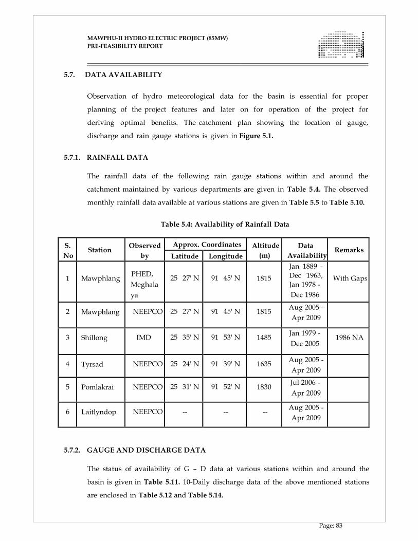
MAWPHU-II HYDRO ELECTRIC PROJECT (85MW)
MAWPHU-II HYDRO ELECTRIC PROJECT (85MW)
PRE-FEASIBILITY REPORT
Page: 83
5.7. DATA AVAILABILITY
Observation of hydro meteorological data for the basin is essential for proper
planning of the project features and later on for operation of the project for
deriving optimal benefits. The catchment plan showing the location of gauge,
discharge and rain gauge stations is given in Figure 5.1.
5.7.1. RAINFALL DATA
The rainfall data of the following rain gauge stations within and around the
catchment maintained by various departments are given in Table 5 .4. The observed
monthly rainfall data available at various stations are given in Table 5.5 to Table 5.10.
Table 5.4: Availability of Rainfall Data
S.
No
Station
Observed
by
Approx. Coordinates Altitude
(m)
Data
Availability
Remarks
Latitude Longitude 1
Mawphlang
PHED,
Meghala
ya
25 27' N
91 45' N
1815
Jan 1889 -
Dec 1963,
Jan 1978 -
Dec 1986
With Gaps
2 Mawphlang
NEEPCO
25 27' N
91 45' N
1815
Aug 2005 -
Apr 2009
3 Shillong
IMD
25 35' N
91 53' N
1485
Jan 1979 -
Dec 2005
1986 NA
4 Tyrsad
NEEPCO
25 24' N
91 39' N
1635
Aug 2005 -
Apr 2009
5 Pomlakrai
NEEPCO
25 31' N
91 52' N
1830
Jul 2006 -
Apr 2009
6 Laitlyndop
NEEPCO
--
--
--
Aug 2005 -
Apr 2009
5.7.2. GAUGE AND DISCHARGE DATA
The status of availability of G – D data at various stations within and around the
basin is given in Table 5.11. 10-Daily discharge data of the above mentioned stations
are enclosed in Table 5.12 and Table 5.14.
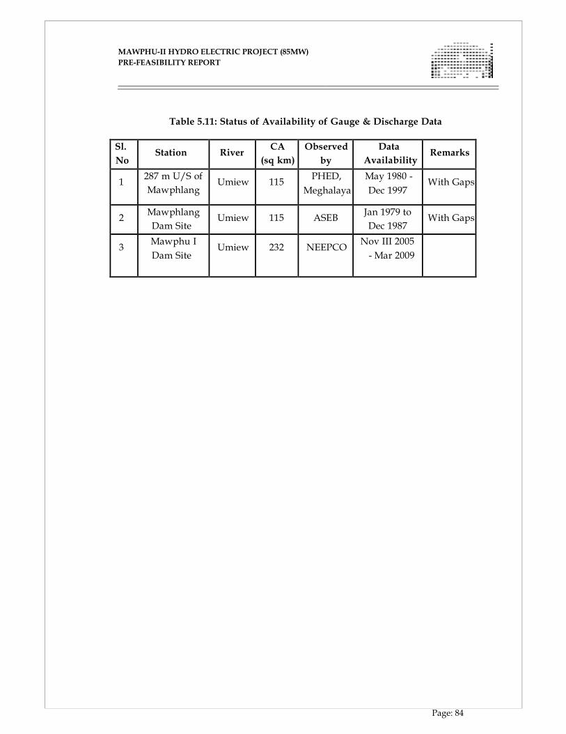
MAWPHU-II HYDRO ELECTRIC PROJECT (85MW)
MAWPHU-II HYDRO ELECTRIC PROJECT (85MW)
PRE-FEASIBILITY REPORT
Page: 84
Table 5.11: Status of Availability of Gauge & Discharge Data
Sl.
No
Station
River
CA
(sq km)
Observed
by
Data
Availability
Remarks
1
287 m U/S of
Mawphlang
Umiew
115
PHED,
Meghalaya
May 1980 -
Dec 1997
With Gaps
2
Mawphlang
Dam Site
Umiew
115
ASEB
Jan 1979 to
Dec 1987
With Gaps
3
Mawphu I
Dam Site
Umiew
232
NEEPCO
Nov III 2005
- Mar 2009
Mawphu-II H.E. Project (85 MW)
Pre-Feasibility Report
Table 5.12: 10 Daily Discharges at Mawphlang observed by PHED (Cumecs)
Page: 85
Mawphu-II H.E. Project (85 MW)
Pre-Feasibility Report
Table 5.13: 10 Daily Discharges at Mawphlang observed by ASEB (Cumecs)
Page: 86
Mawphu-II H.E. Project (85 MW)
Pre-Feasibility Report
Table 5.19: Monthly Discharges at Mawphlang after filling Data Gaps (cumecs)
Page: 87
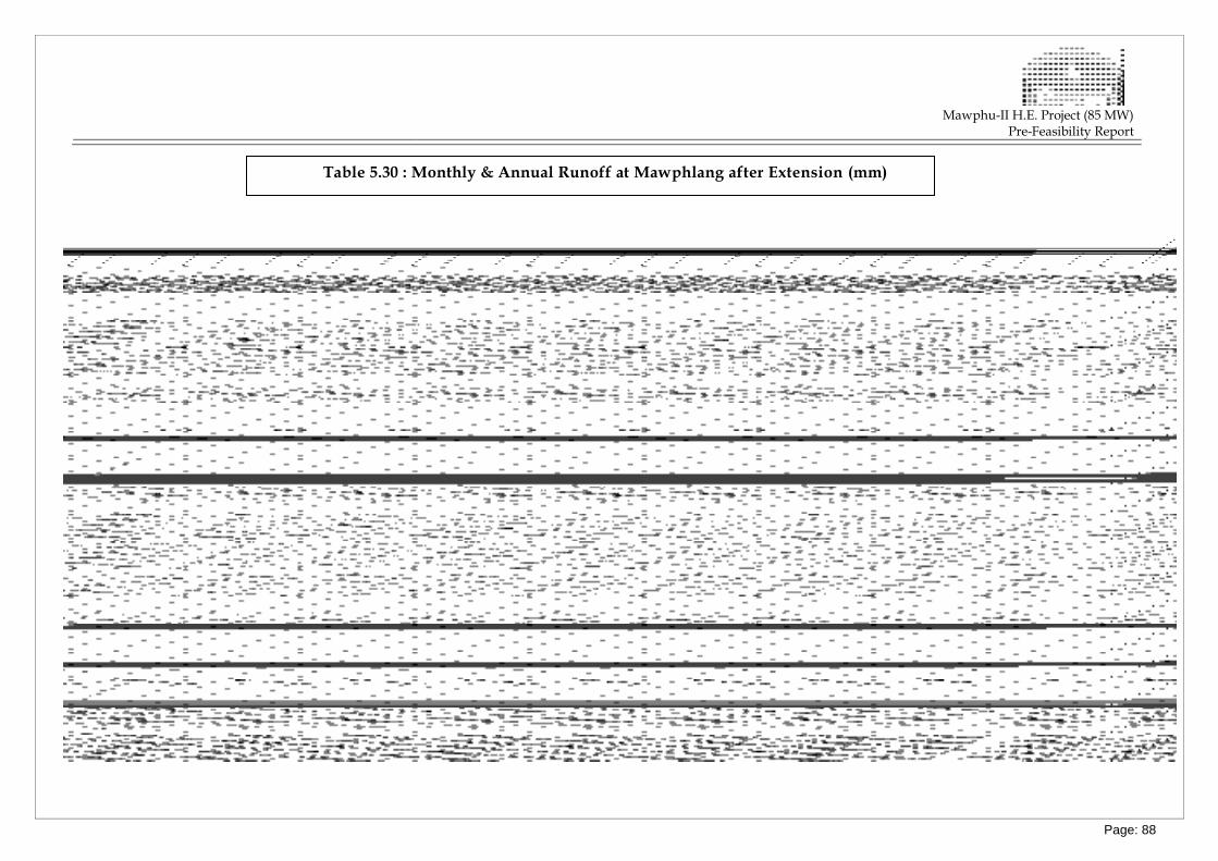
Mawphu-II H.E. Project (85 MW)
Pre-Feasibility Report
Table 5.30 : Monthly & Annual Runoff at Mawphlang after Extension (mm)
Page: 88
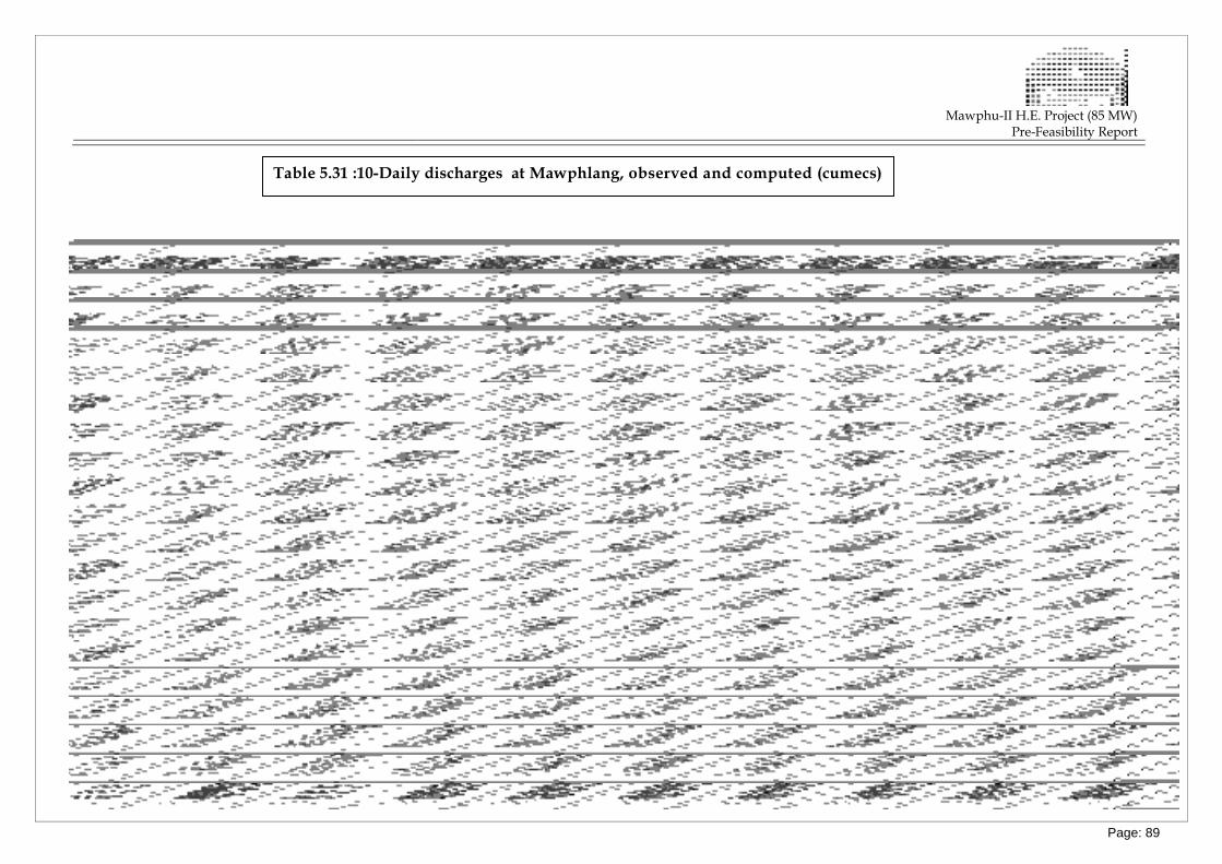
Mawphu-II H.E. Project (85 MW)
Pre-Feasibility Report
Table 5.31 :10-Daily discharges at Mawphlang, observed and computed (cumecs)
Page: 89
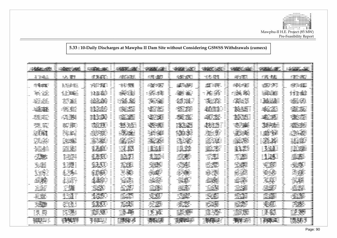
Mawphu-II H.E. Project (85 MW)
Pre-Feasibility Report
5.33 : 10-Daily Discharges at Mawphu II Dam Site without Considering GSWSS Withdrawals (cumecs)
Page: 90
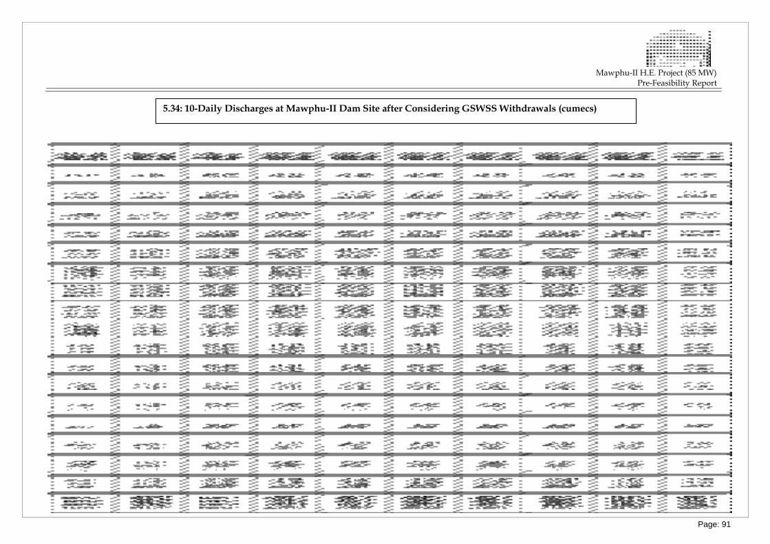
Mawphu-II H.E. Project (85 MW)
Pre-Feasibility Report
5.34: 10-Daily Discharges at Mawphu-II Dam Site after Considering GSWSS Withdrawals (cumecs)
Page: 91
Mawphu-II H.E. Project (85 MW)
Pre-Feasibility Report
Table 5.48: Convolution of UG with Rainfall
Page: 92
Mawphu-II H.E. Project (85 MW)
Pre-Feasibility Report
Fig 5.26: Synthetic Unit Hydrograph
Page: 93
Mawphu-II H.E. Project (85 MW)
Pre-Feasibility Report
Fig 5.28: Design Flood Hydrograph
Page: 94
MAWPHU-II HYDRO ELECTRIC PROJECT (85MW)
MAWPHU-II HYDRO ELECTRIC PROJECT (85MW)
PRE-FEASIBILITY REPORT
Page: 95
5.8. ANALYSIS OF DATA
Detailed calculations on water availability and flood magnitude will lead to selecting
the design features of the project (installed capacity, turbine flow, spillway capacity, etc.).
Those features will directly reflect on the project cost and on the quantity and value of
energy produced. Before utilizing the hydro – meteorological data for the studies, consistency
checks on the data were made to check its accuracy and consistency. Since there were
gaps in the available rainfall and discharge data, the same were filled before subjecting
the data to consistency checks.
5.8.1. FILLING DATA GAPS
a) Shillong Rainfall
On examination of the daily rainfall data at Shillong observed by IMD, it was found
that the daily data for the periods 22nd to 31st October 1979, 27th to 30th June
1980 & 22nd to 23rd November 1982 were not available. These data were filled by
adopting the average value of all other available rainfall data for the concerned days.
The rainfall data for the year 1986 was not available and this year’s data has not
been considered for the studies. From the daily rainfall data, monthly rainfall values
have been computed. It is seen that during the monsoon months (May to October),
there was only one data gap for the month of October 2005. This gap has been
filled by developing relationship between the average monthly rainfalls for the
observed period and the available monthly rainfall during the year 2005. The plot is
given in Figure 5.4. The monthly rainfall data of Shillong after filling the data gap is
given in Table 5.15.
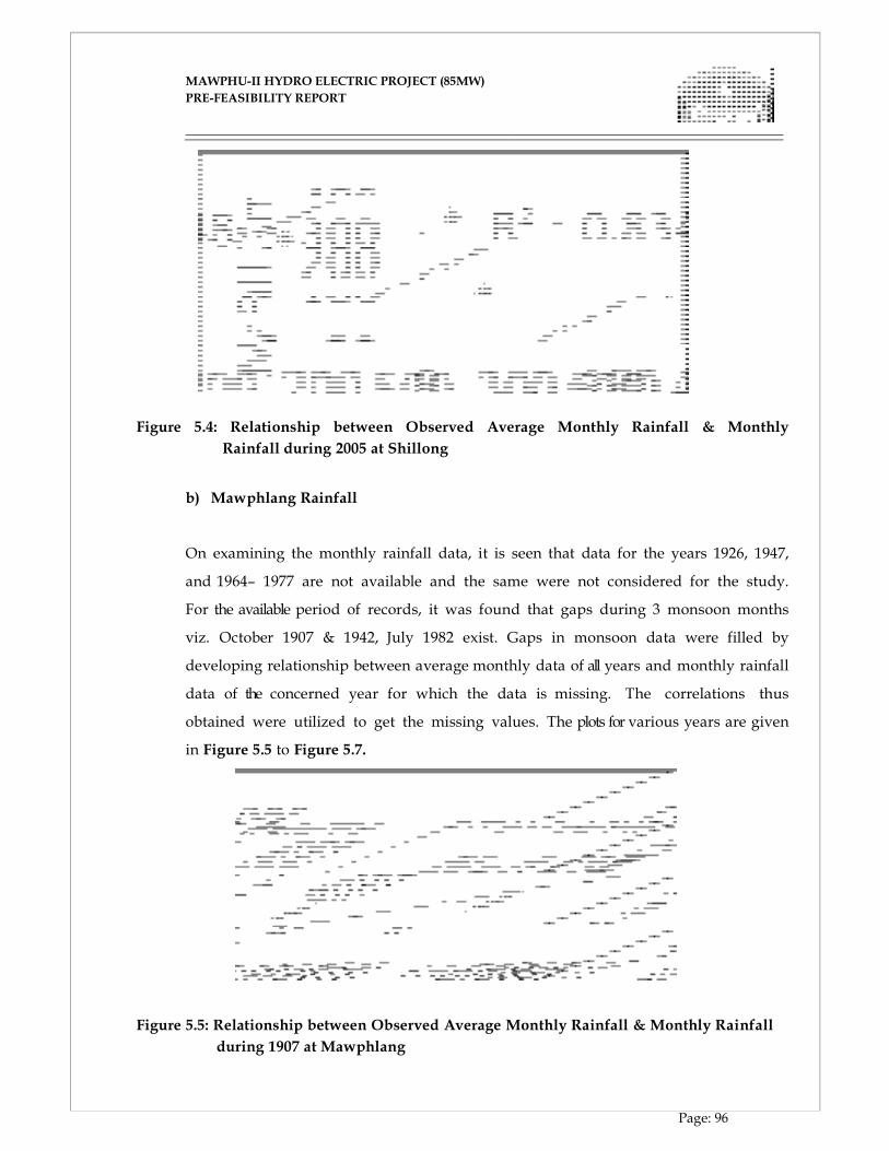
MAWPHU-II HYDRO ELECTRIC PROJECT (85MW)
MAWPHU-II HYDRO ELECTRIC PROJECT (85MW)
PRE-FEASIBILITY REPORT
Page: 96
Figure 5.4: Relationship between Observed Average Monthly Rainfall & Monthly
Rainfall during 2005 at Shillong
b) Mawphlang Rainfall
On examining the monthly rainfall data, it is seen that data for the years 1926, 1947,
and 1964– 1977 are not available and the same were not considered for the study.
For the available period of records, it was found that gaps during 3 monsoon months
viz. October 1907 & 1942, July 1982 exist. Gaps in monsoon data were filled by
developing relationship between average monthly data of all years and monthly rainfall
data of the concerned year for which the data is missing. The correlations thus
obtained were utilized to get the missing values. The plots for various years are given
in Figure 5.5 to Figure 5.7.
Figure 5.5: Relationship between Observed Average Monthly Rainfall & Monthly Rainfall
during 1907 at Mawphlang
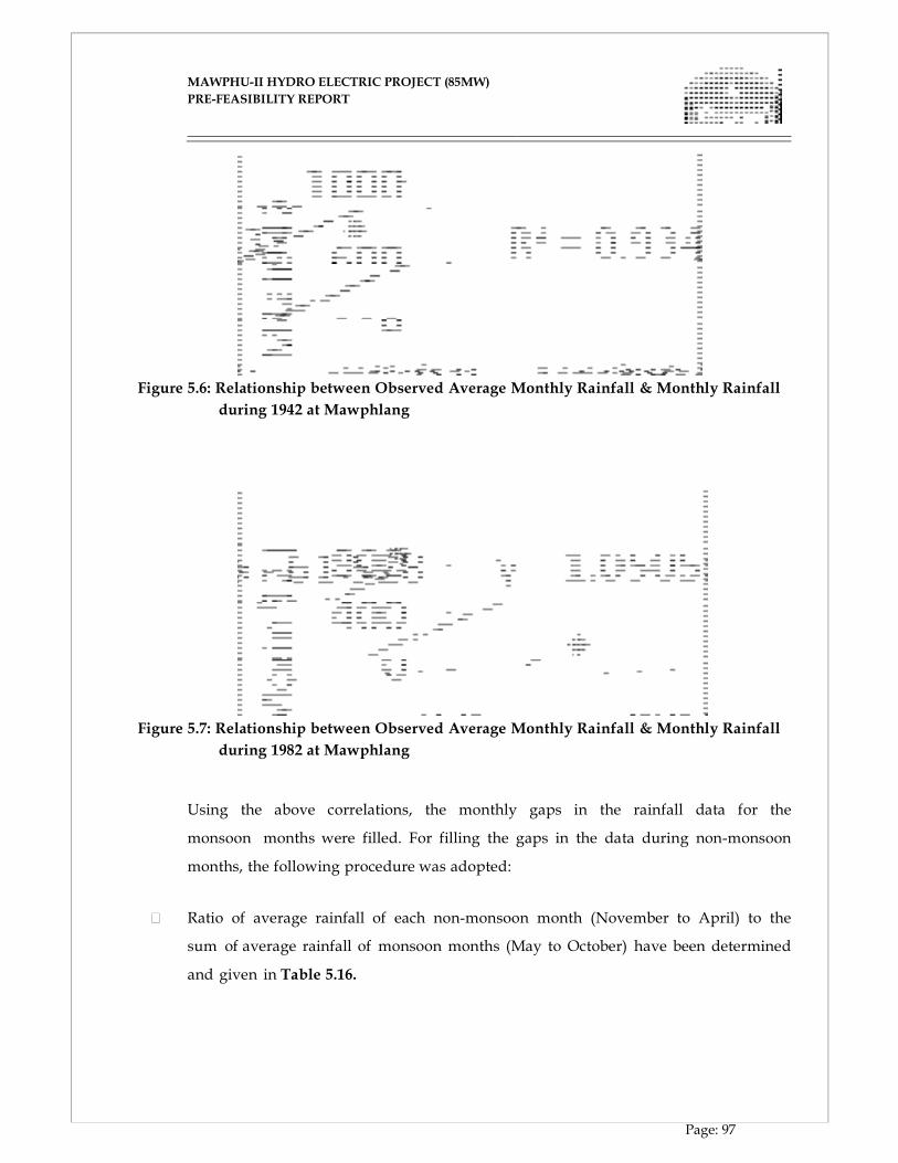
MAWPHU-II HYDRO ELECTRIC PROJECT (85MW)
MAWPHU-II HYDRO ELECTRIC PROJECT (85MW)
PRE-FEASIBILITY REPORT
Page: 97
Figure 5.6: Relationship between Observed Average Monthly Rainfall & Monthly Rainfall
during 1942 at Mawphlang
Figure 5.7: Relationship between Observed Average Monthly Rainfall & Monthly Rainfall
during 1982 at Mawphlang
Using the above correlations, the monthly gaps in the rainfall data for the
monsoon months were filled. For filling the gaps in the data during non-monsoon
months, the following procedure was adopted:
Ratio of average rainfall of each non-monsoon month (November to April) to the
sum of average rainfall of monsoon months (May to October) have been determined
and given in Table 5.16.
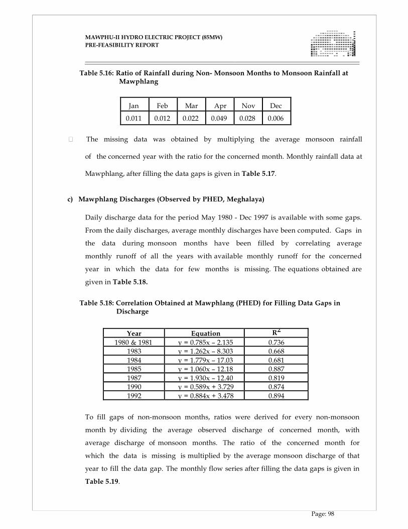
MAWPHU-II HYDRO ELECTRIC PROJECT (85MW)
MAWPHU-II HYDRO ELECTRIC PROJECT (85MW)
PRE-FEASIBILITY REPORT
Page: 98
Table 5.16: Ratio of Rainfall during Non- Monsoon Months to Monsoon Rainfall at Mawphlang
Jan
Feb
Mar
Apr
Nov
Dec
0.011 0.012 0.022 0.049 0.028 0.006 The missing data was obtained by multiplying the average monsoon rainfall
of the concerned year with the ratio for the concerned month. Monthly rainfall data at
Mawphlang, after filling the data gaps is given in Table 5.17.
c) Mawphlang Discharges (Observed by PHED, Meghalaya)
Daily discharge data for the period May 1980 - Dec 1997 is available with some gaps.
From the daily discharges, average monthly discharges have been computed. Gaps in
the data during monsoon months have been filled by correlating average
monthly runoff of all the years with available monthly runoff for the concerned
year in which the data for few months is missing. The equations obtained are
given in Table 5.18.
Table 5.18: Correlation Obtained at Mawphlang (PHED) for Filling Data Gaps in
Discharge
Year Equation R2
1980 & 1981 y = 0.785x – 2.135 0.736
1983 y = 1.262x – 8.303 0.668
1984 y = 1.779x – 17.03 0.681
1985 y = 1.060x – 12.18 0.887
1987 y = 1.930x – 12.40 0.819
1990 y = 0.589x + 3.729 0.874
1992 y = 0.884x + 3.478 0.894
To fill gaps of non-monsoon months, ratios were derived for every non-monsoon
month by dividing the average observed discharge of concerned month, with
average discharge of monsoon months. The ratio of the concerned month for
which the data is missing is multiplied by the average monsoon discharge of that
year to fill the data gap. The monthly flow series after filling the data gaps is given in
Table 5.19.
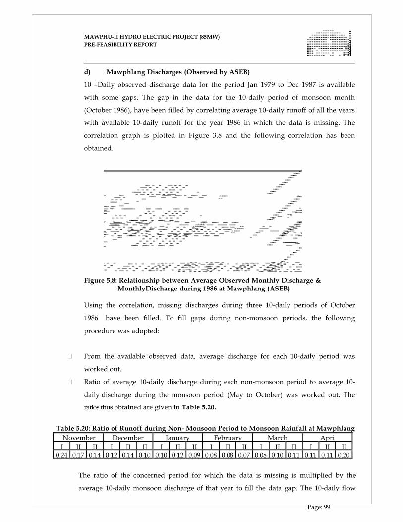
MAWPHU-II HYDRO ELECTRIC PROJECT (85MW)
MAWPHU-II HYDRO ELECTRIC PROJECT (85MW)
PRE-FEASIBILITY REPORT
Page: 99
d) Mawphlang Discharges (Observed by ASEB)
10 –Daily observed discharge data for the period Jan 1979 to Dec 1987 is available
with some gaps. The gap in the data for the 10-daily period of monsoon month
(October 1986), have been filled by correlating average 10-daily runoff of all the years
with available 10-daily runoff for the year 1986 in which the data is missing. The
correlation graph is plotted in Figure 3.8 and the following correlation has been
obtained.
Figure 5.8: Relationship between Average Observed Monthly Discharge & MonthlyDischarge during 1986 at Mawphlang (ASEB)
Using the correlation, missing discharges during three 10-daily periods of October
1986 have been filled. To fill gaps during non-monsoon periods, the following
procedure was adopted:
From the available observed data, average discharge for each 10-daily period was
worked out.
Ratio of average 10-daily discharge during each non-monsoon period to average 10-
daily discharge during the monsoon period (May to October) was worked out. The
ratios thus obtained are given in Table 5.20.
Table 5.20: Ratio of Runoff during Non- Monsoon Period to Monsoon Rainfall at Mawphlang
November December January February March Apri
I II II I II II I II II I II II I II II I II II0.24 0.17 0.14 0.12 0.14 0.10 0.10 0.12 0.09 0.08 0.08 0.07 0.08 0.10 0.11 0.11 0.11 0.20
The ratio of the concerned period for which the data is missing is multiplied by the
average 10-daily monsoon discharge of that year to fill the data gap. The 10-daily flow
MAWPHU-II HYDRO ELECTRIC PROJECT (85MW)
MAWPHU-II HYDRO ELECTRIC PROJECT (85MW)
PRE-FEASIBILITY REPORT
Page: 100
series after filling the data gaps is given in Table 5.21.
5.8.2. CONSISTENCY CHECKS
All the available rainfall and discharge data was catalogued and organized into
consistent data format and then analyzed for consistency and reliability in order to:
Ensure that the records actually reflect the catchment’s behavior;
Eliminate or reduce the effect of extraneous influences;
Eliminate doubtful data.
The following consistency checks were applied:
a) Consistency Checks on Rainfall Data
Consistency of the available rainfall data at 2 stations was checked by following
methods:
I) Single Mass Curve
Single Mass curve and double mass curve techniques have been used to verify the
presence of any systematic error in rainfall values for any rain gauge station.
Since continuous annual rainfall data is not available at Mawphlang and Shillong
stations, cumulative annual rainfalls values have been worked out for the continuous
periods of records at these stations. From the annual rainfall values cumulative
annual rainfall values at Mawphlang and Shillong have been worked out and given
in Table 5.22 & Table 5.23. The mass curves for cumulative rainfall at Mawphlang and
Shillong have been plotted in Figure 5.9 & Figure 5.10 respectively.

MAWPHU-II HYDRO ELECTRIC PROJECT (85MW)
MAWPHU-II HYDRO ELECTRIC PROJECT (85MW)
PRE-FEASIBILITY REPORT
Page: 101
Figure 5.9: Single Mass Curves for Various Rainfall Data Lengths at Mawphlang
Since the mass curves of cumulative rainfall at Mawphlang are nearly straight line, the
rainfall data at Mawphlang, can be concluded to be consistent.
Table 5.22: Annual & Cumulative Rainfall at Mawphlang (mm)
Year
Rainfall (mm)
Year Rainfall (mm)
Annual Annual Cumulative 1937 3693 1899 3,916 3916 1938 4219 1900 2,694 6610 1939 4104 1901 3,314 9924 1940 3995 1902 3,622 13545 1941 4445 1903 3,561 17106 1942 3194 1904 2,748 19854 1943 3586 1905 4,249 24103 1944 6173 1906 4,129 28232 1945 6624 1907 2,603 30835 1946 5553 1908 2,168 33003 1947 NA 1909 2,919 35923 1948 3644 1910 4,875 40798 1949 3875 1911 3,716 44514 1950 2728 1912 3,334 47848 1951 4610 1913 3,596 51445 1952 4498 1914 3,048 54492 1953 3558 1915 3,650 58142 1954 3279 1916 3,828 61970 1955 4167 1917 2,516 64486 1956 5043 1918 4,566 69051 1957 2540 1919 3,011 72062 1958 2284 1920 2,753 74815
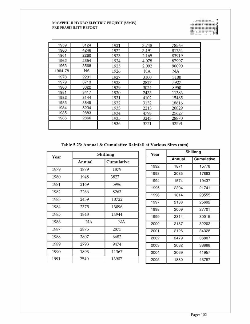
MAWPHU-II HYDRO ELECTRIC PROJECT (85MW)
MAWPHU-II HYDRO ELECTRIC PROJECT (85MW)
PRE-FEASIBILITY REPORT
Page: 102
1959 3124 1921 3,748 78563 1960 4246 1922 3,191 81754 1961 2260 1923 2,165 83919 1962 2354 1924 4,078 87997 1963 3568 1925 2,092 90090
1964-78 NA 1926 NA NA
1978 2231 1927 3100 3100 1979 3713 1928 2827 5927 1980 3022 1929 3024 8950 1981 3417 1930 2433 11383 1982 3144 1931 4102 15485 1983 3845 1932 3132 18616 1984 5234 1933 2213 20829 1985 2883 1934 4798 25627 1986 2866 1935 3243 28870
1936 3721 32591
Table 5.23: Annual & Cumulative Rainfall at Various Sites (mm)
Year
Shillong
Annual Cumulative
1979 1879 1879
1980 1948 3827
1981 2169 5996
1982 2266 8263
1983 2459 10722
1984 2375 13096
1985 1848 14944
1986 NA NA
1987 2875 2875
1988 3807 6682
1989 2793 9474
1990 1893 11367
1991 2540 13907
Year Shillong
Annual Cumulative
1992 1871 15778
1993 2085 17863
1994 1574 19437
1995 2304 21741
1996 1814 23555
1997 2138 25692
1998 2009 27701
1999 2314 30015
2000 2187 32202
2001 2126 34328
2002 2479 36807
2003 2082 38888
2004 3069 41957
2005 1830 43787
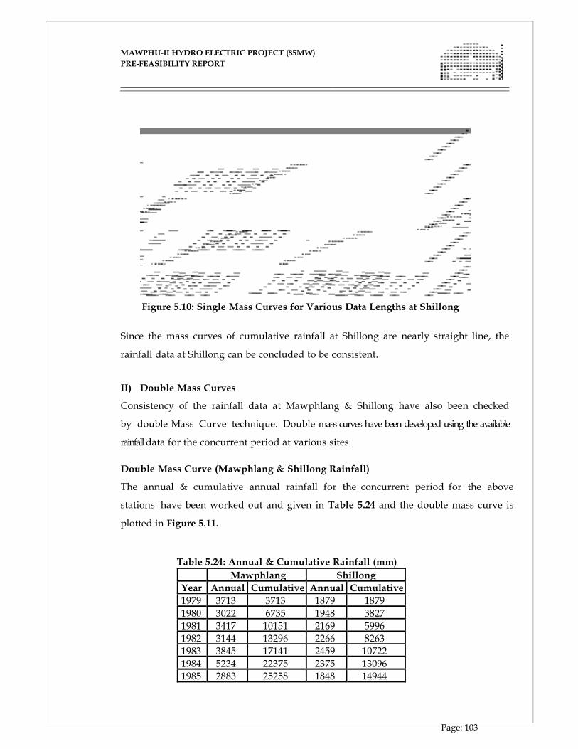
MAWPHU-II HYDRO ELECTRIC PROJECT (85MW)
MAWPHU-II HYDRO ELECTRIC PROJECT (85MW)
PRE-FEASIBILITY REPORT
Page: 103
Figure 5.10: Single Mass Curves for Various Data Lengths at Shillong
Since the mass curves of cumulative rainfall at Shillong are nearly straight line, the
rainfall data at Shillong can be concluded to be consistent.
II) Double Mass Curves
Consistency of the rainfall data at Mawphlang & Shillong have also been checked
by double Mass Curve technique. Double mass curves have been developed using the available
rainfall data for the concurrent period at various sites.
Double Mass Curve (Mawphlang & Shillong Rainfall)
The annual & cumulative annual rainfall for the concurrent period for the above
stations have been worked out and given in Table 5.24 and the double mass curve is
plotted in Figure 5.11.
Table 5.24: Annual & Cumulative Rainfall (mm)
Mawphlang Shillong
Year Annual Cumulative Annual Cumulative
1979 3713 3713 1879 1879
1980 3022 6735 1948 3827
1981 3417 10151 2169 5996
1982 3144 13296 2266 8263
1983 3845 17141 2459 10722
1984 5234 22375 2375 13096
1985 2883 25258 1848 14944
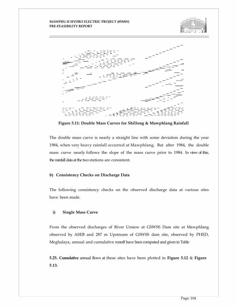
MAWPHU-II HYDRO ELECTRIC PROJECT (85MW)
MAWPHU-II HYDRO ELECTRIC PROJECT (85MW)
PRE-FEASIBILITY REPORT
Page: 104
Figure 5.11: Double Mass Curves for Shillong & Mawphlang Rainfall
The double mass curve is nearly a straight line with some deviation during the year
1984, when very heavy rainfall occurred at Mawphlang. But after 1984, the double
mass curve nearly follows the slope of the mass curve prior to 1984. In view of this,
the rainfall data at the two stations are consistent.
b) Consistency Checks on Discharge Data
The following consistency checks on the observed discharge data at various sites
have been made.
i) Single Mass Curve
From the observed discharges of River Umiew at GSWSS Dam site at Mawphlang
observed by ASEB and 287 m Upstream of GSWSS dam site, observed by PHED,
Meghalaya, annual and cumulative runoff have been computed and given in Table
5.25. Cumulative annual flows at these sites have been plotted in Figure 5.12 & Figure
5.13.
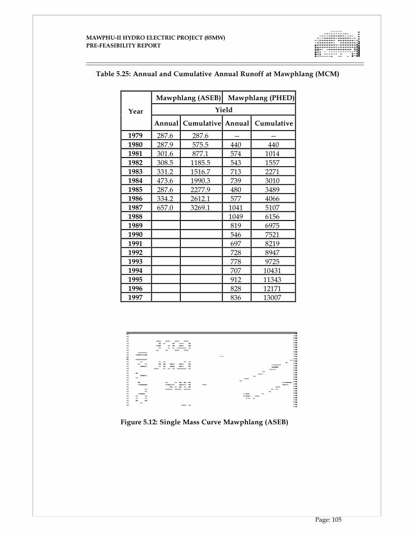
MAWPHU-II HYDRO ELECTRIC PROJECT (85MW)
MAWPHU-II HYDRO ELECTRIC PROJECT (85MW)
PRE-FEASIBILITY REPORT
Page: 105
Table 5.25: Annual and Cumulative Annual Runoff at Mawphlang (MCM)
Year
Mawphlang (ASEB) Mawphlang (PHED)
Yield (MCM)
Annual Cumulative
Annual
Cumulative
1979 287.6 287.6 -- --
1980 287.9 575.5 440 440 1981 301.6 877.1 574 1014
1982 308.5 1185.5 543 1557 1983 331.2 1516.7 713 2271 1984 473.6 1990.3 739 3010 1985 287.6 2277.9 480 3489 1986 334.2 2612.1 577 4066 1987 657.0 3269.1 1041 5107 1988 1049 6156 1989 819 6975 1990 546 7521
1991 697 8219 1992 728 8947 1993 778 9725 1994 707 10431 1995 912 11343 1996 828 12171 1997 836 13007
Figure 5.12: Single Mass Curve Mawphlang (ASEB)
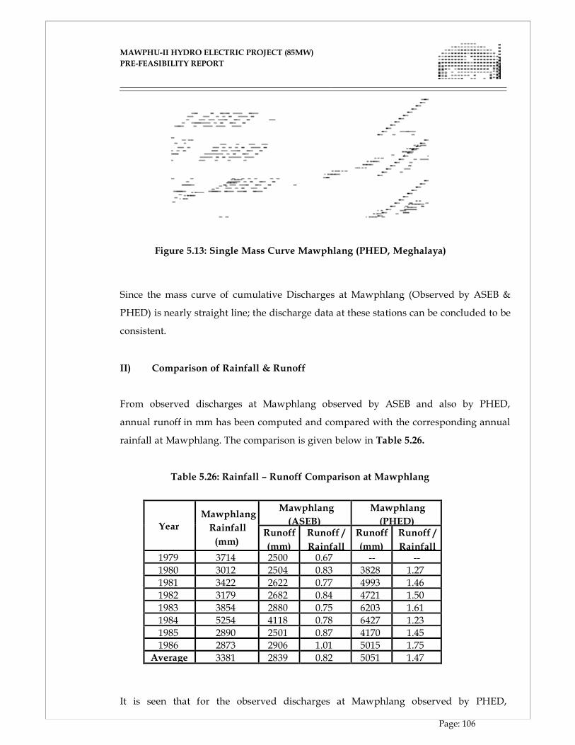
MAWPHU-II HYDRO ELECTRIC PROJECT (85MW)
MAWPHU-II HYDRO ELECTRIC PROJECT (85MW)
PRE-FEASIBILITY REPORT
Page: 106
Figure 5.13: Single Mass Curve Mawphlang (PHED, Meghalaya)
Since the mass curve of cumulative Discharges at Mawphlang (Observed by ASEB &
PHED) is nearly straight line; the discharge data at these stations can be concluded to be
consistent.
II) Comparison of Rainfall & Runoff
From observed discharges at Mawphlang observed by ASEB and also by PHED,
annual runoff in mm has been computed and compared with the corresponding annual
rainfall at Mawphlang. The comparison is given below in Table 5.26.
Table 5.26: Rainfall – Runoff Comparison at Mawphlang
Year
Mawphlang
Rainfall
(mm)
Mawphlang
(ASEB)
Mawphlang
(PHED) Runoff
(mm)
Runoff /
Rainfall
Runoff
(mm)
Runoff /
Rainfall 1979 3714 2500 0.67 -- --
1980 3012 2504 0.83 3828 1.27
1981 3422 2622 0.77 4993 1.46
1982 3179 2682 0.84 4721 1.50
1983 3854 2880 0.75 6203 1.61
1984 5254 4118 0.78 6427 1.23
1985 2890 2501 0.87 4170 1.45
1986 2873 2906 1.01 5015 1.75 Average 3381 2839 0.82 5051 1.47
It is seen that for the observed discharges at Mawphlang observed by PHED,
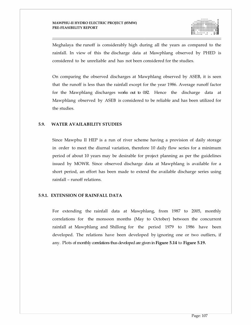
MAWPHU-II HYDRO ELECTRIC PROJECT (85MW)
MAWPHU-II HYDRO ELECTRIC PROJECT (85MW)
PRE-FEASIBILITY REPORT
Page: 107
Meghalaya the runoff is considerably high during all the years as compared to the
rainfall. In view of this the discharge data at Mawphlang observed by PHED is
considered to be unreliable and has not been considered for the studies.
On comparing the observed discharges at Mawphlang observed by ASEB, it is seen
that the runoff is less than the rainfall except for the year 1986. Average runoff factor
for the Mawphlang discharges works out to 0.82. Hence the discharge data at
Mawphlang observed by ASEB is considered to be reliable and has been utilized for
the studies.
5.9. WATER AVAILABILITY STUDIES
Since Mawphu II HEP is a run of river scheme having a provision of daily storage
in order to meet the diurnal variation, therefore 10 daily flow series for a minimum
period of about 10 years may be desirable for project planning as per the guidelines
issued by MOWR. Since observed discharge data at Mawphlang is available for a
short period, an effort has been made to extend the available discharge series using
rainfall – runoff relations.
5.9.1. EXTENSION OF RAINFALL DATA
For extending the rainfall data at Mawphlang, from 1987 to 2005, monthly
correlations for the monsoon months (May to October) between the concurrent
rainfall at Mawphlang and Shillong for the period 1979 to 1986 have been
developed. The relations have been developed by ignoring one or two outliers, if
any. Plots of monthly correlations thus developed are given in Figure 5.14 to Figure 5.19.
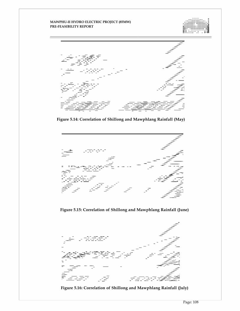
MAWPHU-II HYDRO ELECTRIC PROJECT (85MW)
MAWPHU-II HYDRO ELECTRIC PROJECT (85MW)
PRE-FEASIBILITY REPORT
Page: 108
Figure 5.14: Correlation of Shillong and Mawphlang Rainfall (May)
Figure 5.15: Correlation of Shillong and Mawphlang Rainfall (June)
Figure 5.16: Correlation of Shillong and Mawphlang Rainfall (July)
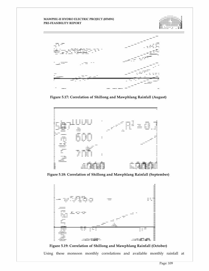
MAWPHU-II HYDRO ELECTRIC PROJECT (85MW)
MAWPHU-II HYDRO ELECTRIC PROJECT (85MW)
PRE-FEASIBILITY REPORT
Page: 109
Figure 5.17: Correlation of Shillong and Mawphlang Rainfall (August)
Figure 5.18: Correlation of Shillong and Mawphlang Rainfall (September)
Figure 5.19: Correlation of Shillong and Mawphlang Rainfall (October)
Using these monsoon monthly correlations and available monthly rainfall at
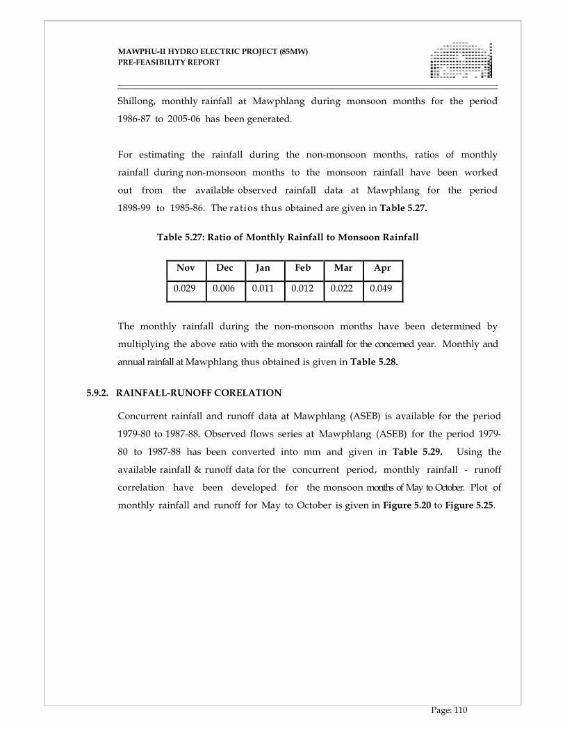
MAWPHU-II HYDRO ELECTRIC PROJECT (85MW)
MAWPHU-II HYDRO ELECTRIC PROJECT (85MW)
PRE-FEASIBILITY REPORT
Page: 110
Shillong, monthly rainfall at Mawphlang during monsoon months for the period
1986-87 to 2005-06 has been generated.
For estimating the rainfall during the non-monsoon months, ratios of monthly
rainfall during non-monsoon months to the monsoon rainfall have been worked
out from the available observed rainfall data at Mawphlang for the period
1898-99 to 1985-86. The ratios thus obtained are given in Table 5.27.
Table 5.27: Ratio of Monthly Rainfall to Monsoon Rainfall
Nov Dec Jan Feb Mar Apr
0.029 0.006 0.011 0.012 0.022 0.049
The monthly rainfall during the non-monsoon months have been determined by
multiplying the above ratio with the monsoon rainfall for the concerned year. Monthly and
annual rainfall at Mawphlang thus obtained is given in Table 5.28.
5.9.2. RAINFALL-RUNOFF CORELATION
Concurrent rainfall and runoff data at Mawphlang (ASEB) is available for the period
1979-80 to 1987-88. Observed flows series at Mawphlang (ASEB) for the period 1979-
80 to 1987-88 has been converted into mm and given in Table 5.29. Using the
available rainfall & runoff data for the concurrent period, monthly rainfall - runoff
correlation have been developed for the monsoon months of May to October. Plot of
monthly rainfall and runoff for May to October is given in Figure 5.20 to Figure 5.25.
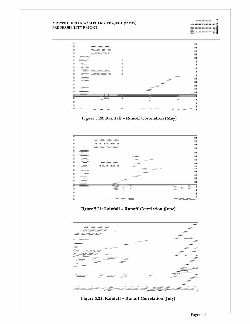
MAWPHU-II HYDRO ELECTRIC PROJECT (85MW)
MAWPHU-II HYDRO ELECTRIC PROJECT (85MW)
PRE-FEASIBILITY REPORT
Page: 111
Figure 5.20: Rainfall – Runoff Correlation (May)
Figure 5.21: Rainfall – Runoff Correlation (June)
Figure 5.22: Rainfall – Runoff Correlation (July)
MAWPHU-II HYDRO ELECTRIC PROJECT (85MW)
MAWPHU-II HYDRO ELECTRIC PROJECT (85MW)
PRE-FEASIBILITY REPORT
Page: 112
Figure 5.23: Rainfall – Runoff Correlation (August)
Figure 5.24: Rainfall – Runoff Correlation (September) f
Figure 5.25: Rainfall – Runoff Correlation (October)
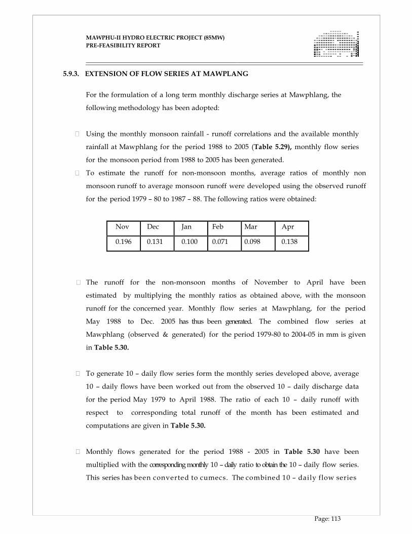
MAWPHU-II HYDRO ELECTRIC PROJECT (85MW)
MAWPHU-II HYDRO ELECTRIC PROJECT (85MW)
PRE-FEASIBILITY REPORT
Page: 113
5.9.3. EXTENSION OF FLOW SERIES AT MAWPLANG For the formulation of a long term monthly discharge series at Mawphlang, the
following methodology has been adopted:
Using the monthly monsoon rainfall - runoff correlations and the available monthly
rainfall at Mawphlang for the period 1988 to 2005 (Table 5.29), monthly flow series
for the monsoon period from 1988 to 2005 has been generated.
To estimate the runoff for non-monsoon months, average ratios of monthly non
monsoon runoff to average monsoon runoff were developed using the observed runoff
for the period 1979 – 80 to 1987 – 88. The following ratios were obtained:
Nov Dec Jan Feb Mar Apr
0.196 0.131 0.100 0.071 0.098 0.138
The runoff for the non-monsoon months of November to April have been
estimated by multiplying the monthly ratios as obtained above, with the monsoon
runoff for the concerned year. Monthly flow series at Mawphlang, for the period
May 1988 to Dec. 2005 has thus been generated. The combined flow series at
Mawphlang (observed & generated) for the period 1979-80 to 2004-05 in mm is given
in Table 5.30.
To generate 10 – daily flow series form the monthly series developed above, average
10 – daily flows have been worked out from the observed 10 – daily discharge data
for the period May 1979 to April 1988. The ratio of each 10 – daily runoff with
respect to corresponding total runoff of the month has been estimated and
computations are given in Table 5.30.
Monthly flows generated for the period 1988 - 2005 in Table 5.30 have been
multiplied with the corresponding monthly 10 – daily ratio to obtain the 10 – daily flow series.
This series has been converted to cumecs. The combined 10 – daily flow series
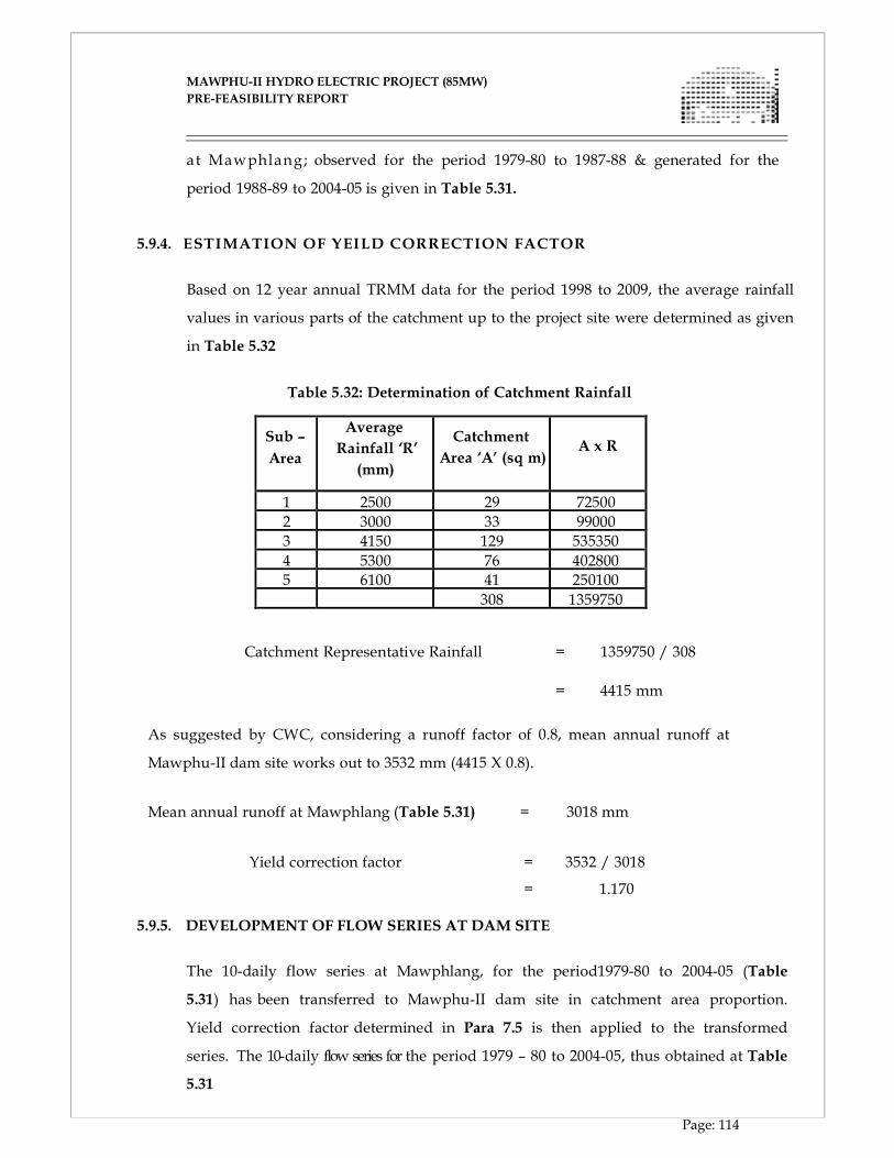
MAWPHU-II HYDRO ELECTRIC PROJECT (85MW)
MAWPHU-II HYDRO ELECTRIC PROJECT (85MW)
PRE-FEASIBILITY REPORT
Page: 114
at Mawphlang; observed for the period 1979-80 to 1987-88 & generated for the
period 1988-89 to 2004-05 is given in Table 5.31.
5.9.4. ESTIMATION OF YEILD CORRECTION FACTOR Based on 12 year annual TRMM data for the period 1998 to 2009, the average rainfall
values in various parts of the catchment up to the project site were determined as given
in Table 5.32
Table 5.32: Determination of Catchment Rainfall
Sub –
Area
Average
Rainfall ‘R’
(mm)
Catchment
Area ‘A’ (sq m)
A x R
1 2500 29 72500
2 3000 33 99000
3 4150 129 535350
4 5300 76 402800
5 6100 41 250100 308 1359750
Catchment Representative Rainfall = 1359750 / 308
=
4415 mm
As suggested by CWC, considering a runoff factor of 0.8, mean annual runoff at
Mawphu-II dam site works out to 3532 mm (4415 X 0.8).
Mean annual runoff at Mawphlang (Table 5.31) = 3018 mm
Yield correction factor = 3532 / 3018
= 1.170
5.9.5. DEVELOPMENT OF FLOW SERIES AT DAM SITE
The 10-daily flow series at Mawphlang, for the period1979-80 to 2004-05 (Table
5.31) has been transferred to Mawphu-II dam site in catchment area proportion.
Yield correction factor determined in Para 7.5 is then applied to the transformed
series. The 10-daily flow series for the period 1979 – 80 to 2004-05, thus obtained at Table
5.31
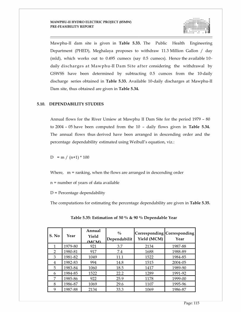
MAWPHU-II HYDRO ELECTRIC PROJECT (85MW)
MAWPHU-II HYDRO ELECTRIC PROJECT (85MW)
PRE-FEASIBILITY REPORT
Page: 115
Mawphu-II dam site is given in Table 5.33. The Public Health Engineering
Department (PHED), Meghalaya proposes to withdraw 11.3 Million Gallon / day
(mld), which works out to 0.495 cumecs (say 0.5 cumecs). Hence the available 10-
daily discharges at Mawphu-II Dam Si te af ter considering the withdrawal by
GSWSS have been determined by subtracting 0.5 cumces from the 10-daily
discharge series obtained in Table 5.33. Available 10-daily discharges at Mawphu-II
Dam site, thus obtained are given in Table 5.34.
5.10. DEPENDABILITY STUDIES
Annual flows for the River Umiew at Mawphu II Dam Site for the period 1979 – 80
to 2004 – 05 have been computed from the 10 – daily flows given in Table 5.34.
The annual flows thus derived have been arranged in descending order and the
percentage dependability estimated using Weibull’s equation, viz.:
D = m / (n+1) * 100
Where, m = ranking, when the flows are arranged in descending order n = number of years of data available D = Percentage dependability The computations for estimating the percentage dependability are given in Table 5.35.
Table 5.35: Estimation of 50 % & 90 % Dependable Year
S. No
Year
Annual
Yield
(MCM)
%
Dependabilit
y
Corresponding
Yield (MCM)
Corresponding
Year
1 1979-80 921 3.7 2134 1987-88
2 1980-81 917 7.4 1688 1988-89
3 1981-82 1049 11.1 1522 1984-85
4 1982-83 994 14.8 1515 2004-05
5 1983-84 1060 18.5 1417 1989-90
6 1984-85 1522 22.2 1289 1991-92
7 1985-86 922 25.9 1178 1999-00
8 1986-87 1069 29.6 1107 1995-96
9 1987-88 2134 33.3 1069 1986-87
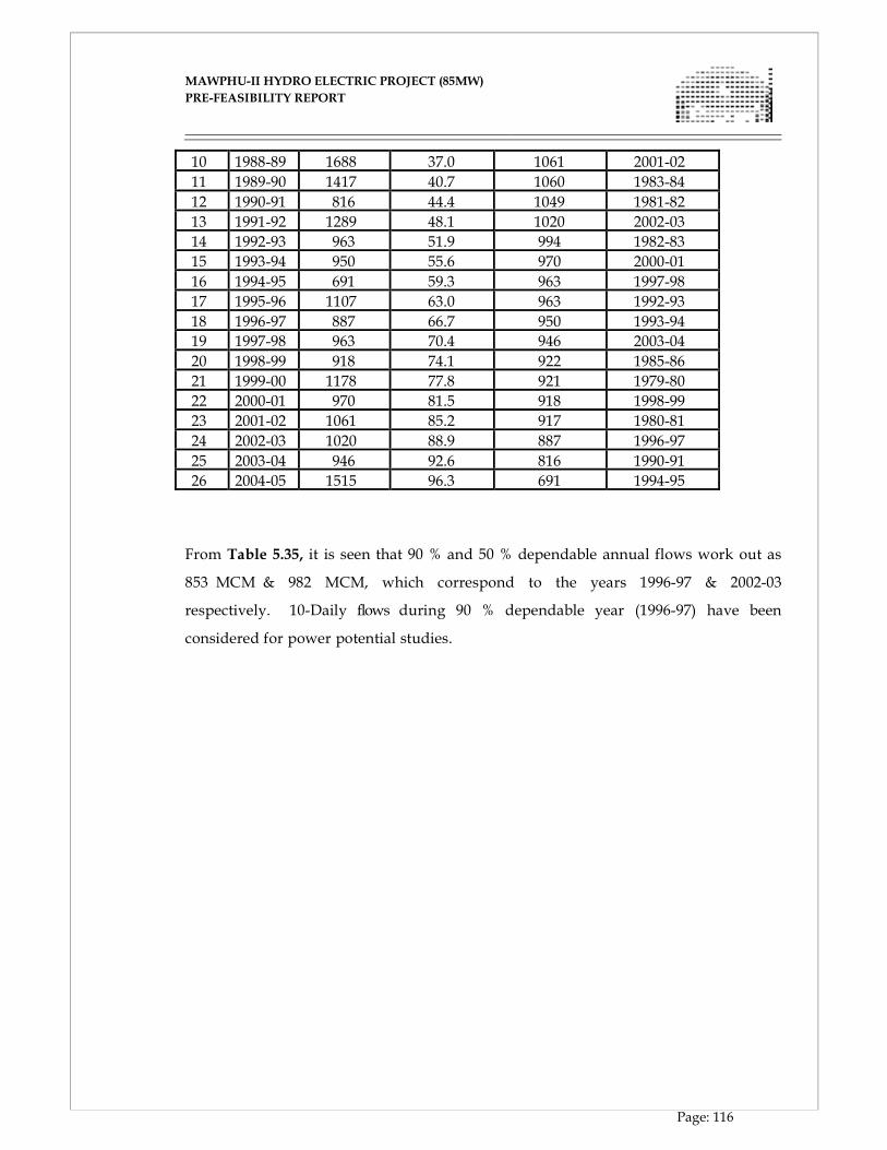
MAWPHU-II HYDRO ELECTRIC PROJECT (85MW)
MAWPHU-II HYDRO ELECTRIC PROJECT (85MW)
PRE-FEASIBILITY REPORT
Page: 116
10 1988-89 1688 37.0 1061 2001-02
11 1989-90 1417 40.7 1060 1983-84
12 1990-91 816 44.4 1049 1981-82
13 1991-92 1289 48.1 1020 2002-03
14 1992-93 963 51.9 994 1982-83
15 1993-94 950 55.6 970 2000-01
16 1994-95 691 59.3 963 1997-98
17 1995-96 1107 63.0 963 1992-93
18 1996-97 887 66.7 950 1993-94
19 1997-98 963 70.4 946 2003-04
20 1998-99 918 74.1 922 1985-86
21 1999-00 1178 77.8 921 1979-80
22 2000-01 970 81.5 918 1998-99
23 2001-02 1061 85.2 917 1980-81
24 2002-03 1020 88.9 887 1996-97
25 2003-04 946 92.6 816 1990-91
26 2004-05 1515 96.3 691 1994-95
From Table 5.35, it is seen that 90 % and 50 % dependable annual flows work out as
853 MCM & 982 MCM, which correspond to the years 1996-97 & 2002-03
respectively. 10-Daily flows during 90 % dependable year (1996-97) have been
considered for power potential studies.
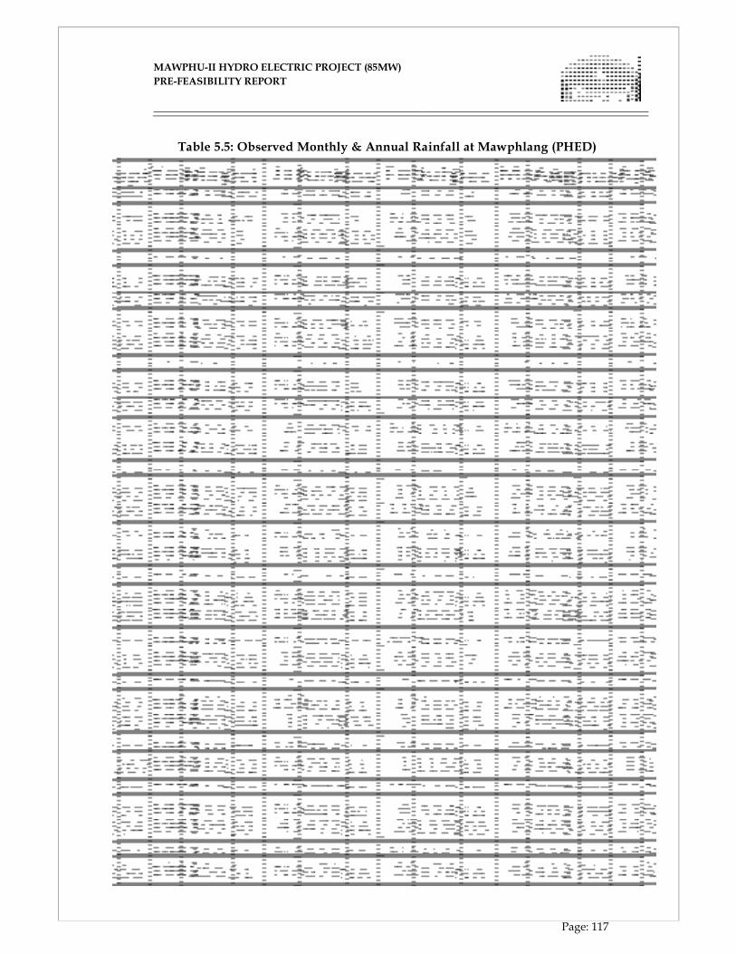
MAWPHU-II HYDRO ELECTRIC PROJECT (85MW)
MAWPHU-II HYDRO ELECTRIC PROJECT (85MW)
PRE-FEASIBILITY REPORT
Page: 117
Table 5.5: Observed Monthly & Annual Rainfall at Mawphlang (PHED)
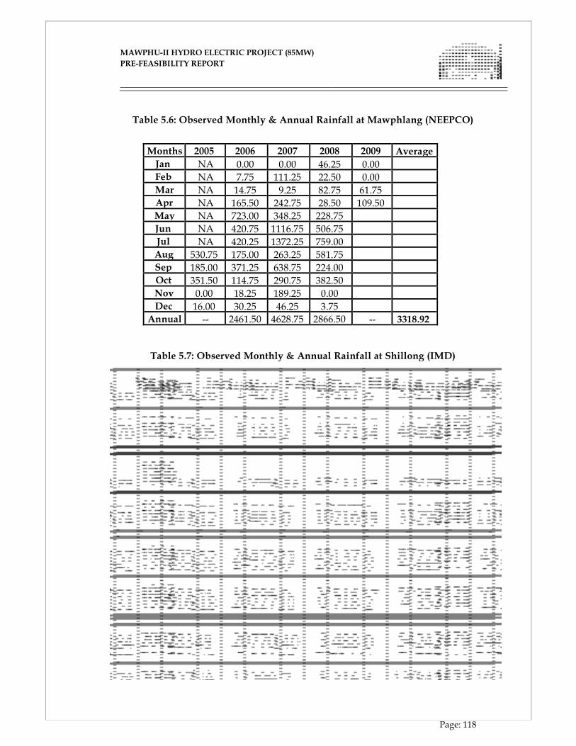
MAWPHU-II HYDRO ELECTRIC PROJECT (85MW)
MAWPHU-II HYDRO ELECTRIC PROJECT (85MW)
PRE-FEASIBILITY REPORT
Page: 118
Table 5.6: Observed Monthly & Annual Rainfall at Mawphlang (NEEPCO)
Months 2005 2006 2007 2008 2009 Average
Jan NA 0.00 0.00 46.25 0.00
Feb NA 7.75 111.25 22.50 0.00
Mar NA 14.75 9.25 82.75 61.75
Apr NA 165.50 242.75 28.50 109.50
May NA 723.00 348.25 228.75
Jun NA 420.75 1116.75 506.75
Jul NA 420.25 1372.25 759.00
Aug 530.75 175.00 263.25 581.75
Sep 185.00 371.25 638.75 224.00
Oct 351.50 114.75 290.75 382.50
Nov 0.00 18.25 189.25 0.00
Dec 16.00 30.25 46.25 3.75
Annual -- 2461.50 4628.75 2866.50 -- 3318.92
Table 5.7: Observed Monthly & Annual Rainfall at Shillong (IMD)
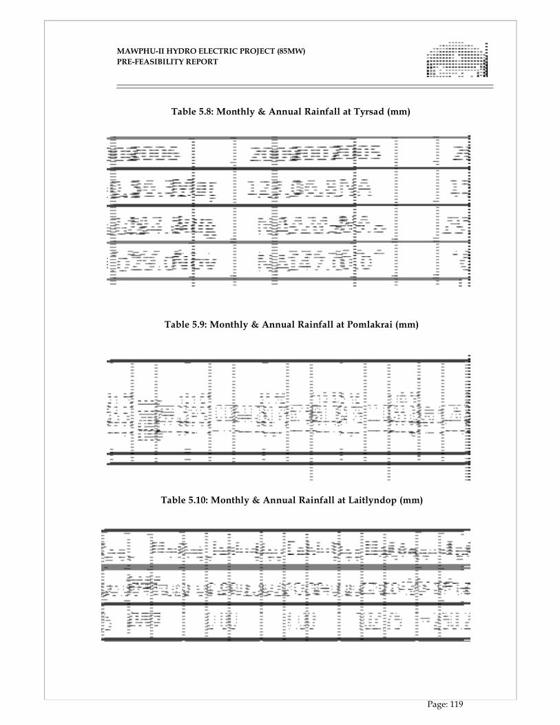
MAWPHU-II HYDRO ELECTRIC PROJECT (85MW)
MAWPHU-II HYDRO ELECTRIC PROJECT (85MW)
PRE-FEASIBILITY REPORT
Page: 119
Table 5.8: Monthly & Annual Rainfall at Tyrsad (mm)
Table 5.9: Monthly & Annual Rainfall at Pomlakrai (mm)
Table 5.10: Monthly & Annual Rainfall at Laitlyndop (mm)
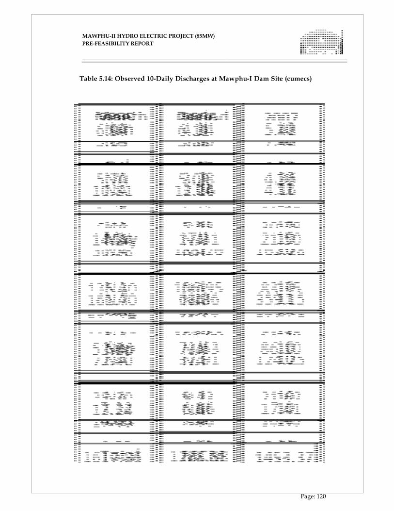
MAWPHU-II HYDRO ELECTRIC PROJECT (85MW)
MAWPHU-II HYDRO ELECTRIC PROJECT (85MW)
PRE-FEASIBILITY REPORT
Page: 120
Table 5.14: Observed 10-Daily Discharges at Mawphu-I Dam Site (cumecs)
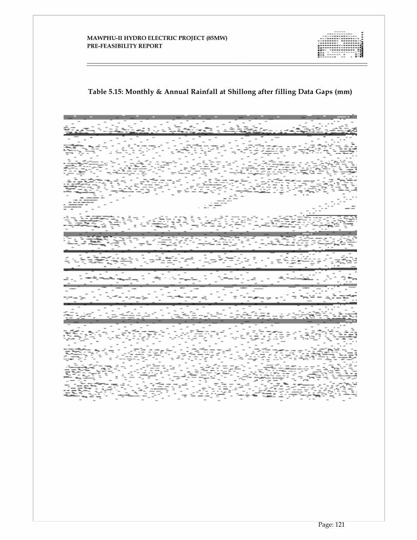
MAWPHU-II HYDRO ELECTRIC PROJECT (85MW)
MAWPHU-II HYDRO ELECTRIC PROJECT (85MW)
PRE-FEASIBILITY REPORT
Page: 121
Table 5.15: Monthly & Annual Rainfall at Shillong after filling Data Gaps (mm)
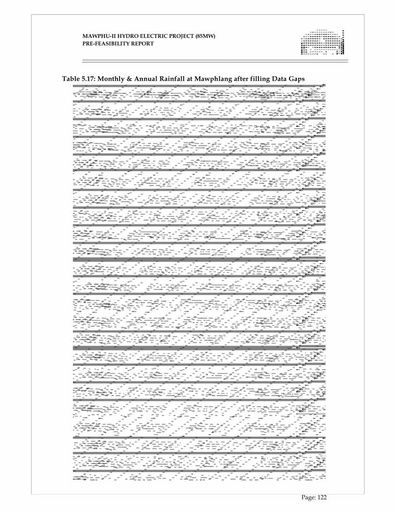
MAWPHU-II HYDRO ELECTRIC PROJECT (85MW)
MAWPHU-II HYDRO ELECTRIC PROJECT (85MW)
PRE-FEASIBILITY REPORT
Page: 122
Table 5.17: Monthly & Annual Rainfall at Mawphlang after filling Data Gaps
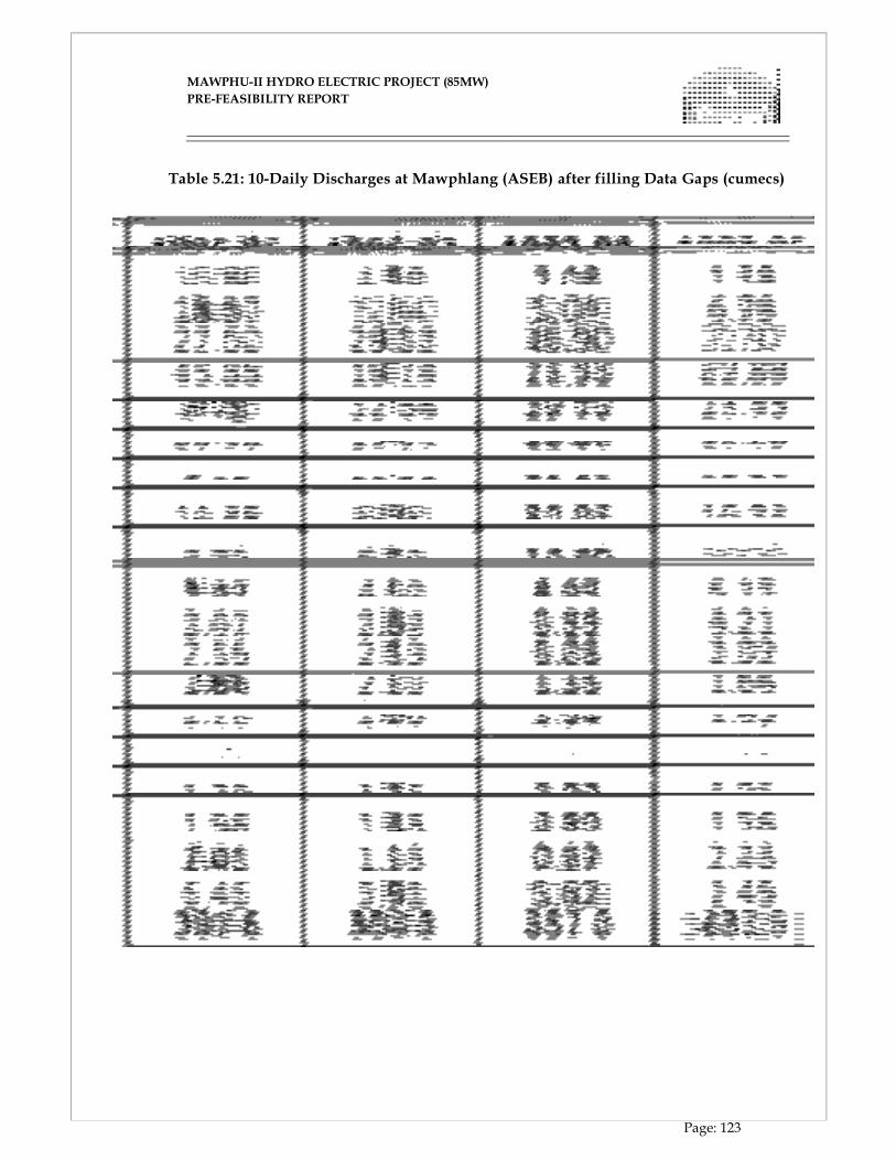
MAWPHU-II HYDRO ELECTRIC PROJECT (85MW)
MAWPHU-II HYDRO ELECTRIC PROJECT (85MW)
PRE-FEASIBILITY REPORT
Page: 123
Table 5.21: 10-Daily Discharges at Mawphlang (ASEB) after filling Data Gaps (cumecs)
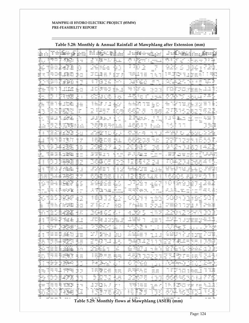
MAWPHU-II HYDRO ELECTRIC PROJECT (85MW)
MAWPHU-II HYDRO ELECTRIC PROJECT (85MW)
PRE-FEASIBILITY REPORT
Page: 124
Table 5.28: Monthly & Annual Rainfall at Mawphlang after Extension (mm)
Table 5.29: Monthly flows at Mawphlang (ASEB) (mm)
MAWPHU-II HYDRO ELECTRIC PROJECT (85MW)
MAWPHU-II HYDRO ELECTRIC PROJECT (85MW)
PRE-FEASIBILITY REPORT
Page: 125
5.11. DESIGN FLOOD STUDIES
Design flood studies are essential for proper planning & functioning of water resource
projects. If the selected design flood is too high, it results in unnecessary costly
structure; while adoption of a low design flood may result in the loss of the structure
itself, causing untold misery to the people downstream, in addition to the damage to
the structure and valuable properties. Hence the selection of design flood involves
the prescription of appropriate value of characteristics feature / features of flood
events for dimensioning of the hydraulic structure to ensure the desired level of
safety commensurate with the economic and social objectives and limitations of the data
and technology available.
5.12. CLASSIFICATION OF DAMS
For design of spillways, the dams have been classified as small, intermediate,
large & very large, depending on the catchment area, gross storage & hydraulic
head. The classification of dams is given in Table 5.36.
Table 5.36: Classification of Dams
Class
Catchment
Area (Sq. km)
Gross
Storage
(MCM)
Hydraulic
Head (m)
Probability of
Design Flood
(Years) Small < 100 0.5 to 10 7.5 to 12 1 in 100
Intermediate 100 to 1,000 10 to 60 12 to 30 1 in 1,000
Large 1,000 to 10,000 60 to 100 30 to 100 1 in 10,000
Very Large > 10,000 > 100 > 100 1 in 1,00,000 5.13. DESIGN FLOOD CRITERIA
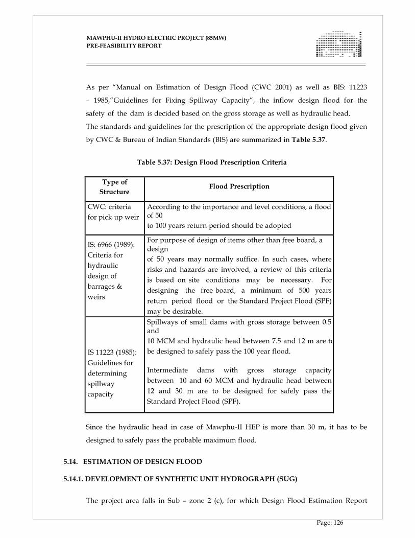
MAWPHU-II HYDRO ELECTRIC PROJECT (85MW)
MAWPHU-II HYDRO ELECTRIC PROJECT (85MW)
PRE-FEASIBILITY REPORT
Page: 126
As per “Manual on Estimation of Design Flood (CWC 2001) as well as BIS: 11223
– 1985,“Guidelines for Fixing Spillway Capacity”, the inflow design flood for the
safety of the dam is decided based on the gross storage as well as hydraulic head.
The standards and guidelines for the prescription of the appropriate design flood given
by CWC & Bureau of Indian Standards (BIS) are summarized in Table 5.37.
Table 5.37: Design Flood Prescription Criteria
Type of
Structure
Flood Prescription
CWC: criteria
for pick up weir
According to the importance and level conditions, a flood of 50
to 100 years return period should be adopted
IS: 6966 (1989):
Criteria for
hydraulic
design of
barrages &
weirs
For purpose of design of items other than free board, a design
of 50 years may normally suffice. In such cases, where
risks and hazards are involved, a review of this criteria
is based on site conditions may be necessary. For
designing the free board, a minimum of 500 years
return period flood or the Standard Project Flood (SPF)
may be desirable. IS 11223 (1985):
Guidelines for
determining
spillway
capacity
Spillways of small dams with gross storage between 0.5 and
10 MCM and hydraulic head between 7.5 and 12 m are to
be designed to safely pass the 100 year flood.
Intermediate dams with gross storage capacity
between 10 and 60 MCM and hydraulic head between
12 and 30 m are to be designed for safely pass the
Standard Project Flood (SPF).
Since the hydraulic head in case of Mawphu-II HEP is more than 30 m, it has to be
designed to safely pass the probable maximum flood.
5.14. ESTIMATION OF DESIGN FLOOD
5.14.1. DEVELOPMENT OF SYNTHETIC UNIT HYDROGRAPH (SUG)
The project area falls in Sub – zone 2 (c), for which Design Flood Estimation Report
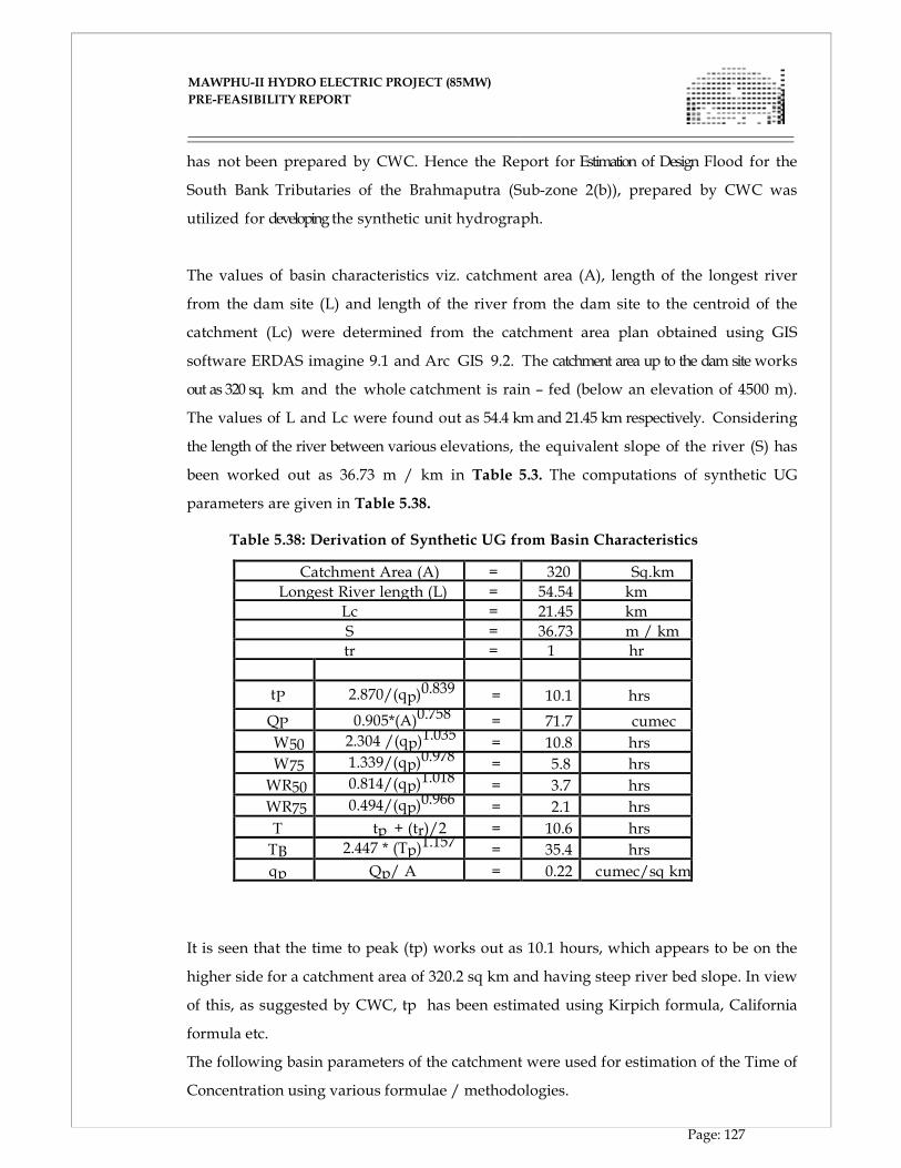
MAWPHU-II HYDRO ELECTRIC PROJECT (85MW)
MAWPHU-II HYDRO ELECTRIC PROJECT (85MW)
PRE-FEASIBILITY REPORT
Page: 127
has not been prepared by CWC. Hence the Report for Estimation of Design Flood for the
South Bank Tributaries of the Brahmaputra (Sub-zone 2(b)), prepared by CWC was
utilized for developing the synthetic unit hydrograph.
The values of basin characteristics viz. catchment area (A), length of the longest river
from the dam site (L) and length of the river from the dam site to the centroid of the
catchment (Lc) were determined from the catchment area plan obtained using GIS
software ERDAS imagine 9.1 and Arc GIS 9.2. The catchment area up to the dam site works
out as 320 sq. km and the whole catchment is rain – fed (below an elevation of 4500 m).
The values of L and Lc were found out as 54.4 km and 21.45 km respectively. Considering
the length of the river between various elevations, the equivalent slope of the river (S) has
been worked out as 36.73 m / km in Table 5.3. The computations of synthetic UG
parameters are given in Table 5.38.
Table 5.38: Derivation of Synthetic UG from Basin Characteristics
Catchment Area (A) = 320 Sq.km
Longest River length (L) = 54.54 km
Lc = 21.45 km
S = 36.73 m / km
tr = 1 hr
tP 2.870/(qp)0.839 = 10.1 hrs
QP 0.905*(A)0.758 = 71.7 cumec
W50 2.304 /(qp)1.035 = 10.8 hrs
W75 1.339/(qp)0.978 = 5.8 hrs
WR50 0.814/(qp)1.018 = 3.7 hrs
WR75 0.494/(qp)0.966 = 2.1 hrs
T
tp + (tr)/2 = 10.6 hrs
TB 2.447 * (Tp)1.157 = 35.4 hrs
qp Qp/ A = 0.22 cumec/sq km
It is seen that the time to peak (tp) works out as 10.1 hours, which appears to be on the
higher side for a catchment area of 320.2 sq km and having steep river bed slope. In view
of this, as suggested by CWC, tp has been estimated using Kirpich formula, California
formula etc.
The following basin parameters of the catchment were used for estimation of the Time of
Concentration using various formulae / methodologies.
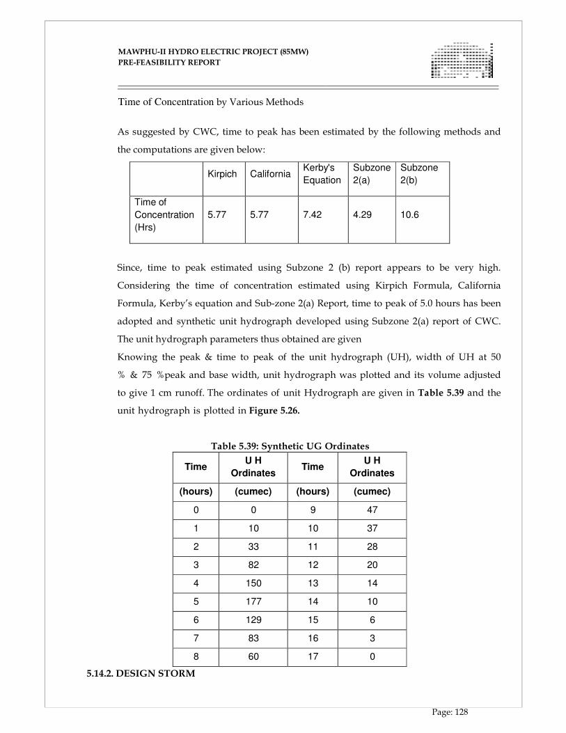
MAWPHU-II HYDRO ELECTRIC PROJECT (85MW)
MAWPHU-II HYDRO ELECTRIC PROJECT (85MW)
PRE-FEASIBILITY REPORT
Page: 128
Time of Concentration by Various Methods
As suggested by CWC, time to peak has been estimated by the following methods and
the computations are given below:
Kirpich
California Kerby's
Equation
Subzone
2(a)
Subzone
2(b)
Time of
Concentration
(Hrs)
5.77
5.77
7.42
4.29
10.6
Since, time to peak estimated using Subzone 2 (b) report appears to be very high.
Considering the time of concentration estimated using Kirpich Formula, California
Formula, Kerby’s equation and Sub-zone 2(a) Report, time to peak of 5.0 hours has been
adopted and synthetic unit hydrograph developed using Subzone 2(a) report of CWC.
The unit hydrograph parameters thus obtained are given
Knowing the peak & time to peak of the unit hydrograph (UH), width of UH at 50
% & 75 %peak and base width, unit hydrograph was plotted and its volume adjusted
to give 1 cm runoff. The ordinates of unit Hydrograph are given in Table 5.39 and the
unit hydrograph is plotted in Figure 5.26.
Table 5.39: Synthetic UG Ordinates
Time U H
Ordinates
Time U H
Ordinates
(hours) (cumec) (hours) (cumec)
0 0 9 47
1 10 10 37
2 33 11 28
3 82 12 20
4 150 13 14
5 177 14 10
6 129 15 6
7 83 16 3
8 60 17 0
5.14.2. DESIGN STORM
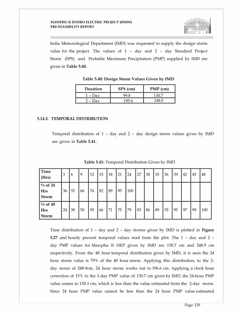
MAWPHU-II HYDRO ELECTRIC PROJECT (85MW)
MAWPHU-II HYDRO ELECTRIC PROJECT (85MW)
PRE-FEASIBILITY REPORT
Page: 129
India Meteorological Department (IMD) was requested to supply the design storm
value for the project. The values of 1 – day and 2 – day Standard Project
Storm (SPS) and Probable Maximum Precipitation (PMP) supplied by IMD are
given in Table 5.40.
Table 5.40: Design Storm Values Given by IMD
Duration SPS (cm) PMP (cm)
1 – Day 99.8 130.7
2 – Day 195.6
5.14.3. TEMPORAL DISTRIBUTION
Temporal distribution of 1 – day and 2 – day design storm values given by IMD
are given in Table 5.41.
Table 5.41: Temporal Distribution Given by IMD
Time
(Hrs)
3 6
9
12
15
18
21
24
27
30
33
36
39
42
45
48
% of 24
Hrs
Storm
36
55
66
74
82
89
95
100
% of 48
Hrs
Storm
24
38
50
59
66
71
75
79
83
86
89
92
95
97
99
100
Time distribution of 1 – day and 2 – day storms given by IMD is plotted in Figure
3.27 and hourly percent temporal values read from the plot. The 1 – day and 2 –
day PMP values for Mawphu II HEP given by IMD are 130.7 cm and 248.9 cm
respectively. From the 48 hour temporal distribution given by IMD, it is seen the 24
hour storm value is 79% of the 48 hour storm. Applying this distribution, to the 2-
day storm of 248.9cm, 24 hour storm works out to 196.6 cm. Applying a clock hour
correction of 15% to the 1-day PMP value of 130.7 cm given by IMD, the 24-hour PMP
value comes to 150.3 cm, which is less than the value estimated from the 2-day storm.
Since 24 hour PMP value cannot be less than the 24 hour PMP value estimated
248.9
MAWPHU-II HYDRO ELECTRIC PROJECT (85MW)
MAWPHU-II HYDRO ELECTRIC PROJECT (85MW)
PRE-FEASIBILITY REPORT
Page: 130
from the 2 – day storm, it is concluded that the temporal distribution of 2-day storm is
not appropriate. Hence the temporal distribution of 1-day storm given by IMD
has been considered. From the plot of 24 hour temporal distribution (Figure
5.27), hourly percent temporal distribution values for 24 - hour storm have been read.
The temporal distribution of 12– hour storm has been obtained by dividing the
temporal distribution of 24 hour by 0.74. The hourly values of temporal distribution
of 24 and 12 hour storm thus obtained are given in Table 5.35.
Figure 5.27: Temporal Distribution Given by IMD
Table 5.42: Temporal Distribution of 24 hr and 12 hr Storm
Since the PMP is assumed to occur in two bells of 12 – hour each, the PMP occurring
during the first 12 hours and later 12 hours of each day storm are 74 % and 26 %
respectively. Hence the PMP values during the 1st & 2nd bells work out as 88.37 cm &
31.05 cm respectively
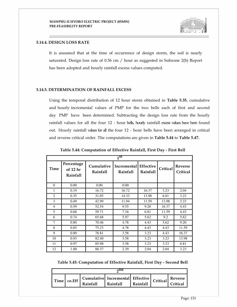
MAWPHU-II HYDRO ELECTRIC PROJECT (85MW)
MAWPHU-II HYDRO ELECTRIC PROJECT (85MW)
PRE-FEASIBILITY REPORT
Page: 131
5.14.4. DESIGN LOSS RATE It is assumed that at the time of occurrence of design storm, the soil is nearly
saturated. Design loss rate of 0.36 cm / hour as suggested in Subzone 2(b) Report
has been adopted and hourly rainfall excess values computed.
5.14.5. DETERMINATION OF RAINFALL EXCESS
Using the temporal distribution of 12 hour storm obtained in Table 5.35, cumulative
and hourly incremental values of PMP for the two bells each of first and second
day PMP have been determined. Subtracting the design loss rate from the hourly
rainfall values for all the four 12 - hour bells, hourly rainfall excess values have been found
out. Hourly rainfall values for all the four 12 - hour bells have been arranged in critical
and reverse critical order. The computations are given in Table 5.44 to Table 5.47.
Table 5.44: Computation of Effective Rainfall, First Day - First Bell
1st
bell Time
Percentage
of 12 hr
Rainfall
Cumulative
Rainfall
Incremental
Rainfall
Effective
Rainfall
Critical
Reverse
Critical
0 0.00 0.00 0.00
1 0.19 16.72 16.72 16.37 3.23 2.04
2 0.35 31.05 14.33 13.98 6.81 3.23
3 0.49 42.99 11.94 11.59 13.98 3.23
4 0.59 52.54 9.55 9.20 16.37 4.43
5 0.68 59.71 7.16 6.81 11.59 4.43
6 0.74 65.68 5.97 5.62 9.2 5.62
7 0.80 70.46 4.78 4.43 5.62 9.20
8 0.85 75.23 4.78 4.43 4.43 11.59
9 0.89 78.81 3.58 3.23 4.43 16.37
10 0.93 82.40 3.58 3.23 3.23 13.98
11 0.97 85.98 3.58 3.23 3.23 6.81
12 1.00 88.37 2.39 2.04 2.04 3.23
Table 5.45: Computation of Effective Rainfall, First Day - Second Bell
2nd
bell Time
co.Eff
Cumulative
Rainfall
Incremental
Rainfall
Effective
Rainfall
Critical
Reverse
Critical
MAWPHU-II HYDRO ELECTRIC PROJECT (85MW)
MAWPHU-II HYDRO ELECTRIC PROJECT (85MW)
PRE-FEASIBILITY REPORT
Page: 132
0 0 0.00 0.00
1 0.19 5.87 5.87 5.52 0.91 0.49
2 0.35 10.91 5.03 4.68 2.17 0.91
3 0.49 15.10 4.20 3.85 4.68 0.91
4 0.59 18.46 3.36 3.01 5.52 1.33
5 0.68 20.98 2.52 2.17 3.85 1.33
6 0.74 23.08 2.10 1.75 3.01 1.75
7 0.80 24.75 1.68 1.33 1.75 3.01
8 0.85 26.43 1.68 1.33 1.33 3.85
9 0.89 27.69 1.26 0.91 1.33 5.52
10 0.93 28.95 1.26 0.91 0.91 4.68
11 0.97 30.21 1.26 0.91 0.91 2.17
12 1.00 31.05 0.84 0.49 0.49 0.91
5.14.6. BASE FLOW
The design base flow of 0.05 cumecs per sq km of the catchment area has been
recommended in the report of sub- zone 2 (b) for the catchments of South Bank
Tributaries of Brahmaputra. Adopting a flow rate of 0.05 cumecs / sq. km, base flow
works out as 16 cumecs.
5.14.7. CONVOLUTION OF DESIGN STORM WITH UG
The effective rainfall values obtained above are applied to 1 hour unit hydrograph
ordinates. The effective rainfall ordinates are arranged against the ordinates of the UH in
such a way that the maximum value of rainfall is placed against the peak value of the UH,
the next lower rainfall values are arranged against the next lower values of the UH in
appropriate order. The order of the effective rainfall values thus obtained is
reversed to get the critical sequence.
To obtain the critical value of the design flood, the arrangement of the rainfall values has
been arranged such that second bell rainfall values precede the first bell rainfall values.
The first rainfall excess value is multiplied with each of the UH ordinate to obtain the
corresponding direct runoff ordinates. The computation is repeated with the
remaining rainfall excess values & the direct surface runoff derived from each
successive rainfall excess is lagged by 1 hour. The total direct surface runoff for various
MAWPHU-II HYDRO ELECTRIC PROJECT (85MW)
MAWPHU-II HYDRO ELECTRIC PROJECT (85MW)
PRE-FEASIBILITY REPORT
Page: 133
time periods is added to get the direct surface runoff hydrograph. The base flow is then
added to each of the direct surface runoff hydrograph ordinate, to get the values of
design flood hydrograph (Probable Maximum Flood) ordinates. The detailed
computations are given in Table 5-48 it is seen that the peak value of the Design Flood is
estimated at 8889 cumecs.
However a PMF of 9970 cumecs has been adopted as per CWC recommendation in
Figure 5.28.
5.14.8. CONCLUSIONS AND RECOMMENDATIONS
A PMF of 9970 cumecs has been adopted as per CWC’s recommendation.
5.15. DIVERSION FLOOD STUDIES
For the design of any diversion work, it is not economically feasible to plan the
diversion for the largest flood that has ever occurred or may be expected to occur.
The diversion flood depends upon the risks involved in case failure of the diversion
structure. For an earth fill dam where, considerable areas of the foundation and the
structure are exposed while under construction, may result in serious damage or loss
of the partially completed work, the importance eliminating the risk of flooding is
relatively great. In case of concrete dam, overtopping / damage to the diversion
structure during the construction of the dam will not have significance adverse
effect.
In view of this, the following design criteria have been considered while planning the
diversion structure for the project.
5.16. DESIGN CRITERIA
The value of diversion flood should be such that the river flow can be
diverted safely by construction of the diversion tunnel or channel and cofferdam, so
that construction of the main dam should go without any hindrance. The following
should be considered while deciding the diversion flood capacity of different structures as
per IS - 14815:2000.
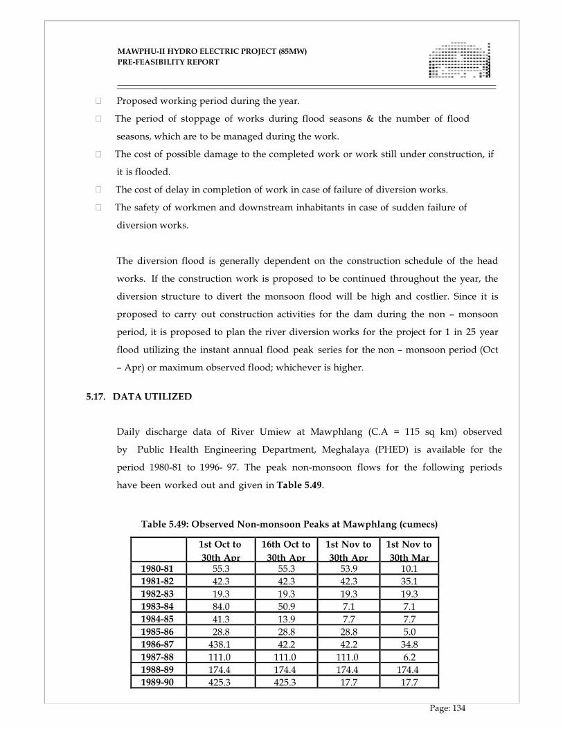
MAWPHU-II HYDRO ELECTRIC PROJECT (85MW)
MAWPHU-II HYDRO ELECTRIC PROJECT (85MW)
PRE-FEASIBILITY REPORT
Page: 134
Proposed working period during the year.
The period of stoppage of works during flood seasons & the number of flood
seasons, which are to be managed during the work.
The cost of possible damage to the completed work or work still under construction, if
it is flooded.
The cost of delay in completion of work in case of failure of diversion works.
The safety of workmen and downstream inhabitants in case of sudden failure of
diversion works.
The diversion flood is generally dependent on the construction schedule of the head
works. If the construction work is proposed to be continued throughout the year, the
diversion structure to divert the monsoon flood will be high and costlier. Since it is
proposed to carry out construction activities for the dam during the non – monsoon
period, it is proposed to plan the river diversion works for the project for 1 in 25 year
flood utilizing the instant annual flood peak series for the non – monsoon period (Oct
– Apr) or maximum observed flood; whichever is higher.
5.17. DATA UTILIZED
Daily discharge data of River Umiew at Mawphlang (C.A = 115 sq km) observed
by Public Health Engineering Department, Meghalaya (PHED) is available for the
period 1980-81 to 1996- 97. The peak non-monsoon flows for the following periods
have been worked out and given in Table 5.49.
Table 5.49: Observed Non-monsoon Peaks at Mawphlang (cumecs)
1st Oct to
30th Apr
16th Oct to
30th Apr
1st Nov to
30th Apr
1st Nov to
30th Mar 1980-81 55.3 55.3 53.9 10.1
1981-82 42.3 42.3 42.3 35.1
1982-83 19.3 19.3 19.3 19.3
1983-84 84.0 50.9 7.1 7.1
1984-85 41.3 13.9 7.7 7.7
1985-86 28.8 28.8 28.8 5.0
1986-87 438.1 42.2 42.2 34.8
1987-88 111.0 111.0 111.0 6.2
1988-89 174.4 174.4 174.4 174.4
1989-90 425.3 425.3 17.7 17.7
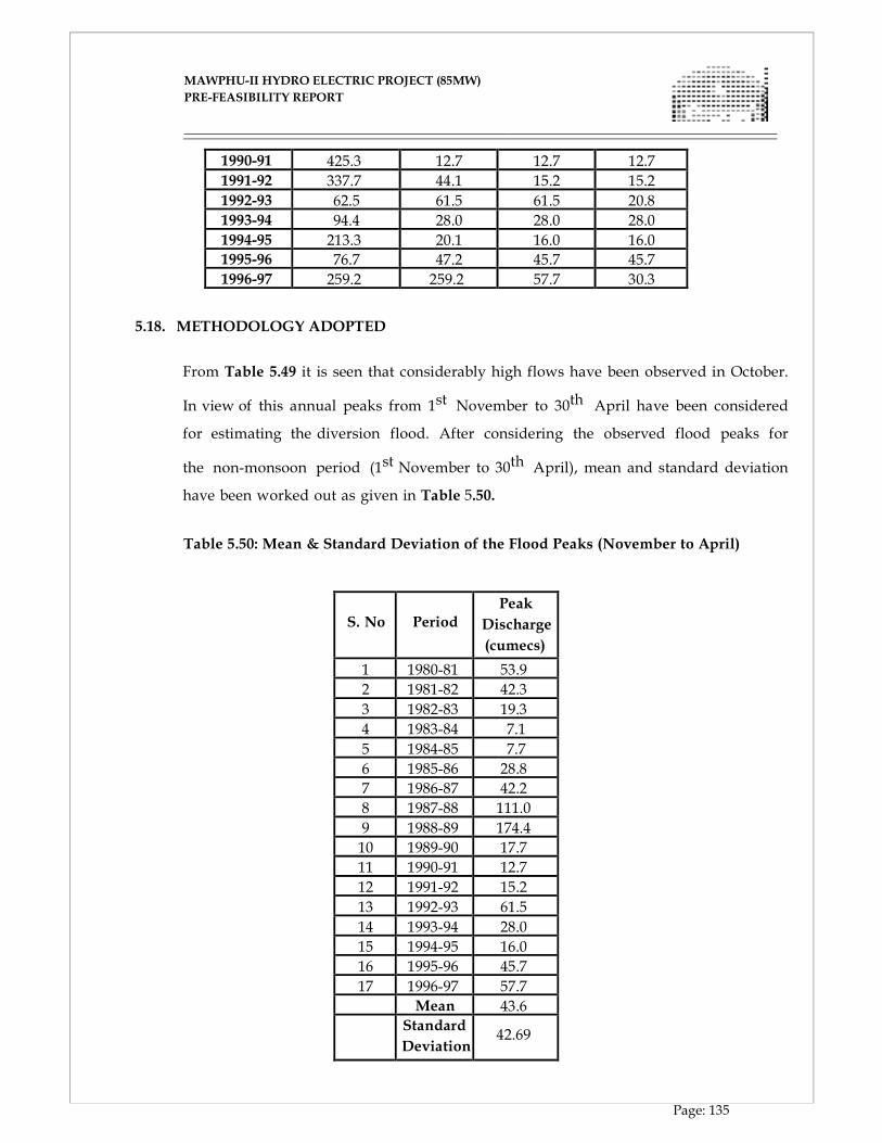
MAWPHU-II HYDRO ELECTRIC PROJECT (85MW)
MAWPHU-II HYDRO ELECTRIC PROJECT (85MW)
PRE-FEASIBILITY REPORT
Page: 135
1990-91 425.3 12.7 12.7 12.7
1991-92 337.7 44.1 15.2 15.2
1992-93 62.5 61.5 61.5 20.8
1993-94 94.4 28.0 28.0 28.0
1994-95 213.3 20.1 16.0 16.0
1995-96 76.7 47.2 45.7 45.7
1996-97 259.2 259.2 57.7 30.3 5.18. METHODOLOGY ADOPTED
From Table 5.49 it is seen that considerably high flows have been observed in October.
In view of this annual peaks from 1st November to 30th April have been considered
for estimating the diversion flood. After considering the observed flood peaks for
the non-monsoon period (1st November to 30th April), mean and standard deviation
have been worked out as given in Table 5.50.
Table 5.50: Mean & Standard Deviation of the Flood Peaks (November to April)
S. No
Period
Peak
Discharge
(cumecs)
1 1980-81 53.9
2 1981-82 42.3
3 1982-83 19.3
4 1983-84 7.1
5 1984-85 7.7
6 1985-86 28.8
7 1986-87 42.2
8 1987-88 111.0
9 1988-89 174.4
10 1989-90 17.7
11 1990-91 12.7
12 1991-92 15.2
13 1992-93 61.5
14 1993-94 28.0
15 1994-95 16.0
16 1995-96 45.7
17 1996-97 57.7 Mean 43.6 Standard
Deviation
42.69
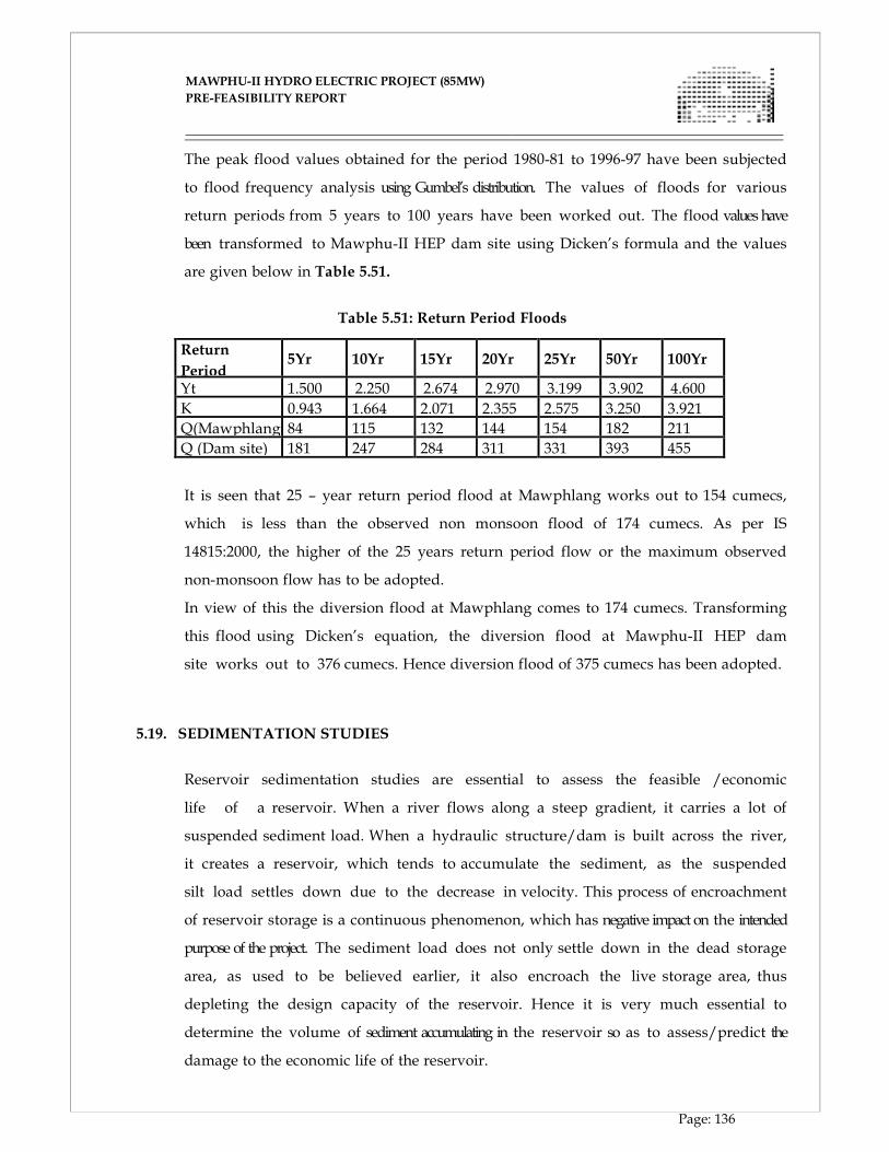
MAWPHU-II HYDRO ELECTRIC PROJECT (85MW)
MAWPHU-II HYDRO ELECTRIC PROJECT (85MW)
PRE-FEASIBILITY REPORT
Page: 136
The peak flood values obtained for the period 1980-81 to 1996-97 have been subjected
to flood frequency analysis using Gumbel’s distribution. The values of floods for various
return periods from 5 years to 100 years have been worked out. The flood values have
been transformed to Mawphu-II HEP dam site using Dicken’s formula and the values
are given below in Table 5.51.
Table 5.51: Return Period Floods
Return
Period
5Yr
10Yr
15Yr
20Yr
25Yr
50Yr
100Yr
Yt 1.500 2.250 2.674 2.970 3.199 3.902 4.600
K 0.943 1.664 2.071 2.355 2.575 3.250 3.921
Q(Mawphlang 84 115 132 144 154 182 211
Q (Dam site) 181 247 284 311 331 393 455
It is seen that 25 – year return period flood at Mawphlang works out to 154 cumecs,
which is less than the observed non monsoon flood of 174 cumecs. As per IS
14815:2000, the higher of the 25 years return period flow or the maximum observed
non-monsoon flow has to be adopted.
In view of this the diversion flood at Mawphlang comes to 174 cumecs. Transforming
this flood using Dicken’s equation, the diversion flood at Mawphu-II HEP dam
site works out to 376 cumecs. Hence diversion flood of 375 cumecs has been adopted.
5.19. SEDIMENTATION STUDIES
Reservoir sedimentation studies are essential to assess the feasible /economic
life of a reservoir. When a river flows along a steep gradient, it carries a lot of
suspended sediment load. When a hydraulic structure/dam is built across the river,
it creates a reservoir, which tends to accumulate the sediment, as the suspended
silt load settles down due to the decrease in velocity. This process of encroachment
of reservoir storage is a continuous phenomenon, which has negative impact on the intended
purpose of the project. The sediment load does not only settle down in the dead storage
area, as used to be believed earlier, it also encroach the live storage area, thus
depleting the design capacity of the reservoir. Hence it is very much essential to
determine the volume of sediment accumulating in the reservoir so as to assess/predict the
damage to the economic life of the reservoir.
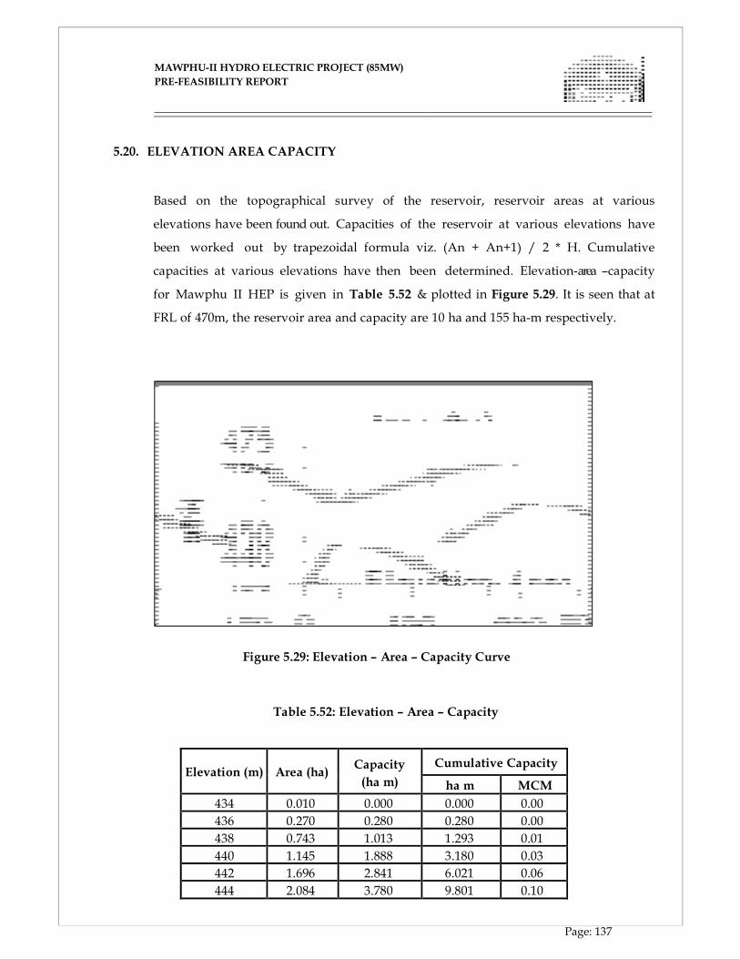
MAWPHU-II HYDRO ELECTRIC PROJECT (85MW)
MAWPHU-II HYDRO ELECTRIC PROJECT (85MW)
PRE-FEASIBILITY REPORT
Page: 137
5.20. ELEVATION AREA CAPACITY
Based on the topographical survey of the reservoir, reservoir areas at various
elevations have been found out. Capacities of the reservoir at various elevations have
been worked out by trapezoidal formula viz. (An + An+1) / 2 * H. Cumulative
capacities at various elevations have then been determined. Elevation-area –capacity
for Mawphu II HEP is given in Table 5.52 & plotted in Figure 5.29. It is seen that at
FRL of 470m, the reservoir area and capacity are 10 ha and 155 ha-m respectively.
Figure 5.29: Elevation – Area – Capacity Curve
Table 5.52: Elevation – Area – Capacity
Elevation (m)
Area (ha)
Capacity
(ha m)
Cumulative Capacity
ha m MCM
434 0.010 0.000 0.000 0.00
436 0.270 0.280 0.280 0.00
438 0.743 1.013 1.293 0.01
440 1.145 1.888 3.180 0.03
442 1.696 2.841 6.021 0.06
444 2.084 3.780 9.801 0.10
MAWPHU-II HYDRO ELECTRIC PROJECT (85MW)
MAWPHU-II HYDRO ELECTRIC PROJECT (85MW)
PRE-FEASIBILITY REPORT
Page: 138
446 2.794 4.878 14.679 0.15
448 3.048 5.842 20.521 0.21
450 3.330 6.378 26.899 0.27
452 3.886 7.215 34.114 0.34
454 4.469 8.355 42.470 0.42
456 5.180 9.650 52.119 0.52
458 5.846 11.026 63.146 0.63
460 6.438 12.285 75.430 0.75
462 6.938 13.376 88.807 0.89
464 7.514 14.452 103.258 1.03
466 8.006 15.519 118.777 1.19
468 9.137 17.142 135.920 1.36
470 9.990 19.127 155.047 1.55 5.21. DATA REQUIREMENT
The required data for sedimentation studies is deepest river bed level at the dam
site, Full Reservoir Level (FRL), average annual flow, annual rate of sedimentation,
catchment area and the elevation – area – capacity curve / Table for the reservoir.
5.22. LONG TERM ANNUAL AVERAGE SEDIMENTATION RATE
Presently sediment observations of Umiew River at the project site or any other site
are not available. Sediment observations for Kynshi HEP in the adjacent basin have
been made for the period 2001 – 2008. Based on this observed data, sediment rate for
Kynshi HEP has been estimated as 0.3 mm / year. This sediment rate appears to be
low, as the sediment rate of Himalayan Rivers, as recommended by Central Water
Commission (CWC) is 1 mm /sq km/year. Hence sediment rate of 1 mm / sq km /
year has been adopted for the studies.
5.23. CLASSIFICATION OF SEDIMENT PROBLEM
For determination of severity of the sedimentation problem, the capacity inflow
ratio (C/I) is worked out.
Gross capacity (C) at FRL = 1.55 MCM
MAWPHU-II HYDRO ELECTRIC PROJECT (85MW)
MAWPHU-II HYDRO ELECTRIC PROJECT (85MW)
PRE-FEASIBILITY REPORT
Page: 139
Long term average = 1114.13
As per Brune’s curve, trap efficiency = 0.5 %, which indicates that most of the sediment
will not be trapped in the reservoir and would flow downstream.
The above capacity-inflow ratio clearly indicates that the storage capacity of the
project is very small as compared to the average annual inflow. Therefore Mawphu-II
HEP is virtually a diversion scheme and not a storage scheme. Hence detailed sediment
studies to determine the New Zero Elevation and revised areas and capacities after
70-year sedimentation are not necessary. For effective management of the reservoir,
proper sediment management measures have to be taken.
5.24. SEDIMENT MANAGEMENT MEASURES
Since Mawphu-II HEP is virtually a diversion scheme and not a storage scheme, the
following design aspects have been provided for the purpose of silt management:
operating the reservoir at MDDL during the monsoon months to route the
incoming sediment downstream of the project site.
Provision of low level sluice spillway crest for flushing the silt downstream
during flood season.
Reservoir drawdown flushing two times every year, to ensure that live storage is
always available.
Adequate vertical separation between the water conductor intake sill level and the
sluice spillway crest level for effective silt flushing.

CHAPTER - VI
POWER POTENTIAL & INSTALLED CAPACITY
MAWPHU-II HYDRO ELECTRIC PROJECT (85MW)
MAWPHU-II HYDRO ELECTRIC PROJECT (85MW)
PRE-FEASIBILITY REPORT
Page: 140
CHAPTER - VI
POWER POTENTIAL STUDIES
6.1. GENERAL
Mawphu-II Hydroelectric Pro ject is located in East Khasi Hi l ls distr ic t of
Meghalaya. The diversion dam is located at lat itude 25o18’32”N and Longitude
91o38’19”E. The project is envisaged as Run-of- River scheme with diurnal pondage
for peaking benefits.
The Project is proposed to be constructed utilizing the discharges of the river
Umiew by constructing a diversion structure, intake arrangement, water conductor
system comprising of head race tunnel, surge shaft and pressure shaft. The power is
proposed to be generated in a surface powerhouse with tail race channel to evacuate
the water from the turbines which will flow back to the river.
The power potential studies have been carried out for working out the Installed
Capacity and other project features.
6.2. PROJECT PARAMETERS Following parameters have been considered for carrying out the power potential
studies.
1.
Full reservoir level, FRL
EL 470.00m
2.
Minimum draw down level, MDDL
EL 464.00m
3.
Normal tail water level, TWL
EL 232.00m
4.
Head loss in water conductor system
5.5m
5.
Combined efficiency of Turbine and Generators,
92.12%
6.
Rated Head
230.5 m
7.
Live storage
0.5 Million Cubic meter (MCM)
MAWPHU-II HYDRO ELECTRIC PROJECT (85MW)
MAWPHU-II HYDRO ELECTRIC PROJECT (85MW)
PRE-FEASIBILITY REPORT
Page: 141
The minimum draw down level of the Project has been raised from EL 460m to EL 464m,
for better silt management in consultation with the Central Water Commission.
6.3. HEAD COMPUTATION
For energy generation the head computations have been done as below:
Gross head = FRL – TWL = 470 – 232 = 238m,
Rated net head = (MDDL + (2/3) (FRL – MDDL) – TWL) – Losses in water conductor
system,
= (464 + (2/3) (470 – 464) – 232) - 5.5 = 230.5m
6.4. WATER AVAILABILITY
The data on water availability is available for 26 years i.e. from year 1979-80 to 2004-
05 and is indicated in (Annexure-1). The environment releases as per guidelines of Ministry of
Environment and Forests (MoEF) are as below:
During monsoon months i.e. from June to September, the water to be released from the
Dam has to be 30% of the river discharge. During transition months i.e. post-monsoon
of October and November, and pre-monsoon of April and May, the water to be
released has to be 25% of the river discharge and during lean season i.e. from
December to March, the water to be released will be 20% of the river discharge.
For computing the available discharges for power generation, environment
releases as mentioned above have been deducted from the available discharges.
6.5. DEPENDABLE FLOWS
The dependable flows for analysis of installed capacity etc. are based on 90%
dependable year as per guidelines of CEA. For obtaining the dependable flows, unrestricted energy
generation has been computed for all the 26 years and arranged in descending order of
the energy values. (Annexure-2).
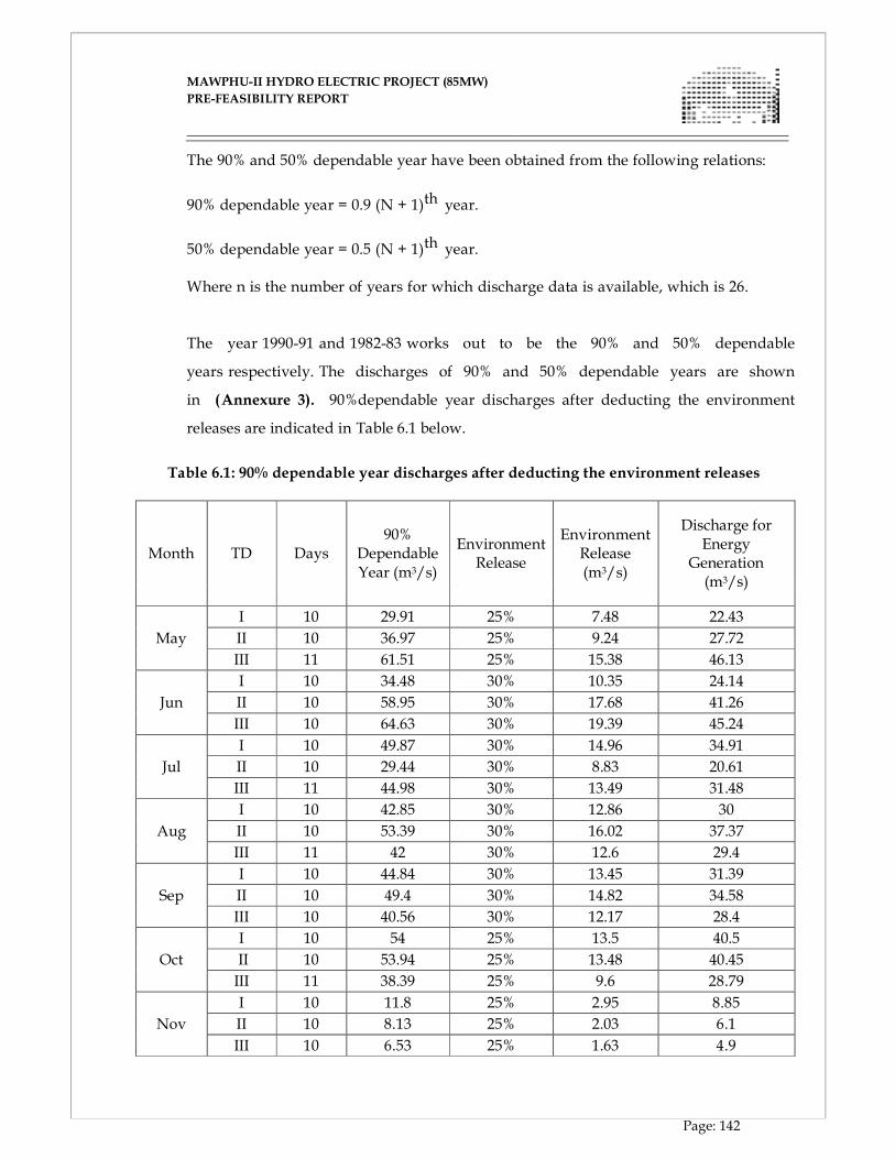
MAWPHU-II HYDRO ELECTRIC PROJECT (85MW)
MAWPHU-II HYDRO ELECTRIC PROJECT (85MW)
PRE-FEASIBILITY REPORT
Page: 142
The 90% and 50% dependable year have been obtained from the following relations:
90% dependable year = 0.9 (N + 1)th year.
50% dependable year = 0.5 (N + 1)th year. Where n is the number of years for which discharge data is available, which is 26.
The year 1990-91 and 1982-83 works out to be the 90% and 50% dependable
years respectively. The discharges of 90% and 50% dependable years are shown
in (Annexure 3). 90%dependable year discharges after deducting the environment
releases are indicated in Table 6.1 below.
Table 6.1: 90% dependable year discharges after deducting the environment releases
Month TD Days 90%
Dependable Year (m3/s)
Environment Release
Environment Release (m3/s)
Discharge for Energy Generation (m3/s)
May
I 10 29.91 25% 7.48 22.43
II 10 36.97 25% 9.24 27.72
III 11 61.51 25% 15.38 46.13
Jun
I 10 34.48 30% 10.35 24.14
II 10 58.95 30% 17.68 41.26
III 10 64.63 30% 19.39 45.24
Jul
I 10 49.87 30% 14.96 34.91
II 10 29.44 30% 8.83 20.61
III 11 44.98 30% 13.49 31.48
Aug
I 10 42.85 30% 12.86 30
II 10 53.39 30% 16.02 37.37
III 11 42 30% 12.6 29.4
Sep
I 10 44.84 30% 13.45 31.39
II 10 49.4 30% 14.82 34.58
III 10 40.56 30% 12.17 28.4
Oct
I 10 54 25% 13.5 40.5
II 10 53.94 25% 13.48 40.45
III 11 38.39 25% 9.6 28.79
Nov
I 10 11.8 25% 2.95 8.85
II 10 8.13 25% 2.03 6.1
III 10 6.53 25% 1.63 4.9
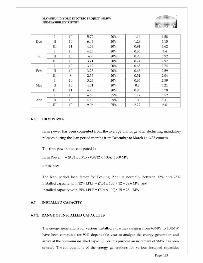
MAWPHU-II HYDRO ELECTRIC PROJECT (85MW)
MAWPHU-II HYDRO ELECTRIC PROJECT (85MW)
PRE-FEASIBILITY REPORT
Page: 143
Dec
I 10 5.72 20% 1.14 4.58
II 10 6.44 20% 1.29 5.15
III 11 4.53 20% 0.91 3.62
Jan
I 10 4.25 20% 0.85 3.4
II 10 4.9 20% 0.98 3.92
III 10 3.71 20% 0.74 2.97
Feb
I 10 3.42 20% 0.68 2.74
II 10 3.23 20% 0.65 2.59
III 8 2.55 20% 0.51 2.04
Mar
I 10 3.23 20% 0.65 2.59
II 10 4.01 20% 0.8 3.21
III 11 4.73 20% 0.95 3.78
Apr
I 10 4.69 25% 1.17 3.52
II 10 4.42 25% 1.1 3.31
III 10 9.06 25% 2.27 6.8
6.6. FIRM POWER
Firm power has been computed from the average discharge after deducting mandatory
releases during the lean period months from December to March i.e. 3.38 cumecs.
The firm power, thus computed is:
Firm Power = (9.81 x 230.5 x 0.9212 x 3.38)/ 1000 MW
= 7.04 MW
The lean period load factor for Peaking Plant is normally between 12% and 25%.
Installed capacity with 12% LPLF = (7.04 x 100)/ 12 = 58.6 MW, and
Installed capacity with 25% LPLF = (7.04 x 100)/ 25 = 28.1 MW
6.7 INSTALLED CAPACITY
6.7.1. RANGE OF INSTALLED CAPACITIES
The energy generations for various installed capacities ranging from 60MW to 100MW
have been computed for 90% dependable year to analyze the energy generation and
arrive at the optimum installed capacity. For this purpose an increment of 5MW has been
selected. The computations of the energy generations for various installed capacities
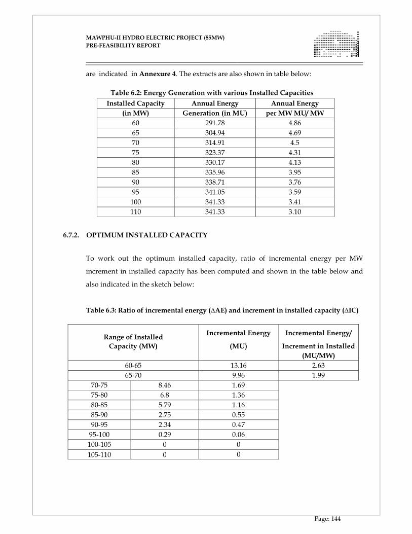
MAWPHU-II HYDRO ELECTRIC PROJECT (85MW)
MAWPHU-II HYDRO ELECTRIC PROJECT (85MW)
PRE-FEASIBILITY REPORT
Page: 144
are indicated in Annexure 4. The extracts are also shown in table below:
Table 6.2: Energy Generation with various Installed Capacities
Installed Capacity Annual Energy Annual Energy
(in MW) Generation (in MU) per MW MU/ MW
60 291.78 4.86
65 304.94 4.69
70 314.91 4.5
75 323.37 4.31
80 330.17 4.13
85 335.96 3.95
90 338.71 3.76
95 341.05 3.59
100 341.33 3.41
110 341.33 3.10
6.7.2. OPTIMUM INSTALLED CAPACITY
To work out the optimum installed capacity, ratio of incremental energy per MW
increment in installed capacity has been computed and shown in the table below and
also indicated in the sketch below:
Table 6.3: Ratio of incremental energy (∆AE) and increment in installed capacity (∆IC)
Range of Installed
Incremental Energy Incremental Energy/
Capacity (MW) (MU) Increment in Installed
(MU/MW)
60-65 13.16 2.63
65-70 9.96 1.99
70-75 8.46 1.69
75-80 6.8 1.36
80-85 5.79 1.16
85-90 2.75 0.55
90-95 2.34 0.47
95-100 0.29 0.06
100-105 0 0
105-110 0 0
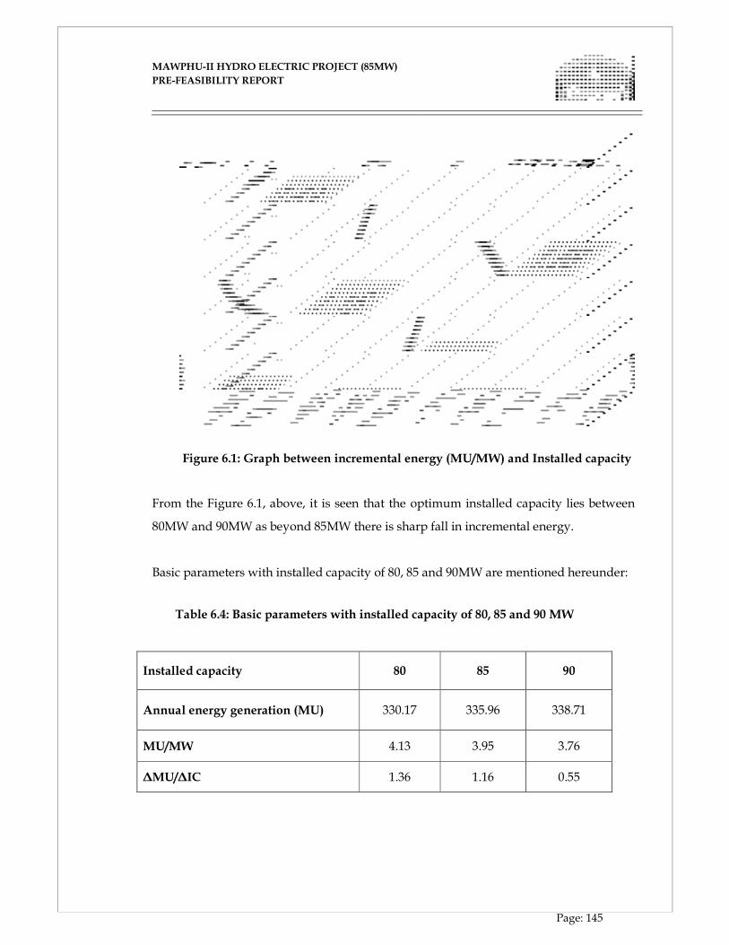
MAWPHU-II HYDRO ELECTRIC PROJECT (85MW)
MAWPHU-II HYDRO ELECTRIC PROJECT (85MW)
PRE-FEASIBILITY REPORT
Page: 145
Figure 6.1: Graph between incremental energy (MU/MW) and Installed capacity
From the Figure 6.1, above, it is seen that the optimum installed capacity lies between
80MW and 90MW as beyond 85MW there is sharp fall in incremental energy.
Basic parameters with installed capacity of 80, 85 and 90MW are mentioned hereunder:
Table 6.4: Basic parameters with installed capacity of 80, 85 and 90 MW
Installed capacity 80 85 90
Annual energy generation (MU) 330.17 335.96 338.71
MU/MW 4.13 3.95 3.76
∆MU/∆IC 1.36 1.16 0.55
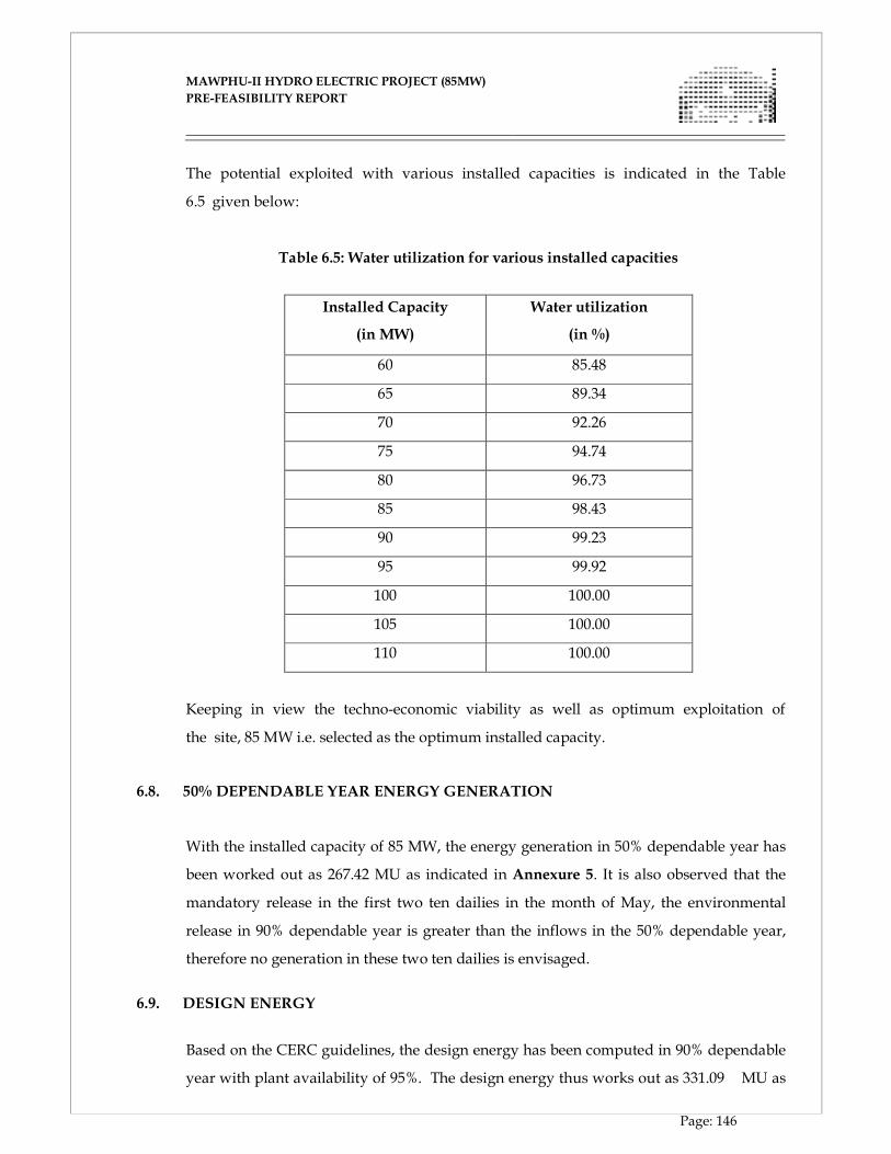
MAWPHU-II HYDRO ELECTRIC PROJECT (85MW)
MAWPHU-II HYDRO ELECTRIC PROJECT (85MW)
PRE-FEASIBILITY REPORT
Page: 146
The potential exploited with various installed capacities is indicated in the Table
6.5 given below:
Table 6.5: Water utilization for various installed capacities
Installed Capacity
(in MW)
Water utilization
(in %)
60 85.48
65 89.34
70 92.26
75 94.74
80 96.73
85 98.43
90 99.23
95 99.92
100 100.00
105 100.00
110 100.00
Keeping in view the techno-economic viability as well as optimum exploitation of
the site, 85 MW i.e. selected as the optimum installed capacity.
6.8. 50% DEPENDABLE YEAR ENERGY GENERATION
With the installed capacity of 85 MW, the energy generation in 50% dependable year has
been worked out as 267.42 MU as indicated in Annexure 5. It is also observed that the
mandatory release in the first two ten dailies in the month of May, the environmental
release in 90% dependable year is greater than the inflows in the 50% dependable year,
therefore no generation in these two ten dailies is envisaged.
6.9. DESIGN ENERGY
Based on the CERC guidelines, the design energy has been computed in 90% dependable
year with plant availability of 95%. The design energy thus works out as 331.09 MU as
MAWPHU-II HYDRO ELECTRIC PROJECT (85MW)
MAWPHU-II HYDRO ELECTRIC PROJECT (85MW)
PRE-FEASIBILITY REPORT
Page: 147
X
indicated in Annexure 6.
6.10. ANNUAL PLANT LOAD FACTOR
The annual plant load factor for the Project is worked out as below:
PLF = (335.96 x 10, 00,000(kWh)/ {85000(kW) X 365(days) X 24(hrs)} X 100
i.e. 45.12%.
6.11. LEAN PERIOD LOAD FACTOR
Lean period load factor = x 100 = 7.04/ 85 x 100 = 8.28%
Firm power is the power considering the average inflows in the lean period from
December to March after deducting the mandatory releases.
6.12 PEAKING OPERATION
For peaking operation for three hours during lean months, the storage required
will be: Design discharge x Peaking time x 3600
Design Discharge = (85x1000)/ (0.9212x230.5) x 9.81=40.80 Cumec
Thus, the storage required = 40.80 x 3 x 3600 ~ 0.4407 Million cubic meters (MCM)
The available live storage between the full reservoir level and the minimum draw
down level is about 0.5 Million cubic meters. The additional storage available would
be utilized to meet contingencies.
6.13 NUMBER OF UNITS
The number of units for any plant are chosen based on reliability
consideration and transportation constraints, it is proposed to install 2 (two) units
of 42.5MW each keeping in view the reliability of operation of the plant. No difficulty
100
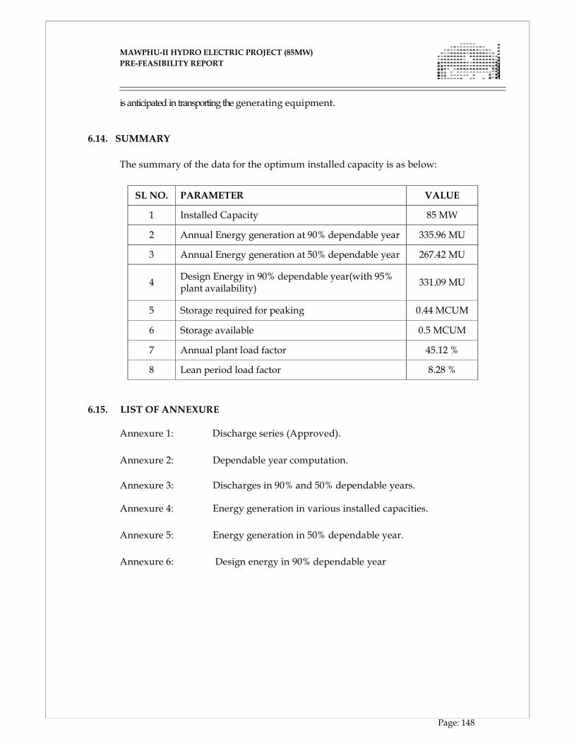
MAWPHU-II HYDRO ELECTRIC PROJECT (85MW)
MAWPHU-II HYDRO ELECTRIC PROJECT (85MW)
PRE-FEASIBILITY REPORT
Page: 148
is anticipated in transporting the generating equipment.
6.14. SUMMARY The summary of the data for the optimum installed capacity is as below:
SL NO. PARAMETER VALUE
1 Installed Capacity 85 MW
2 Annual Energy generation at 90% dependable year 335.96 MU
3 Annual Energy generation at 50% dependable year 267.42 MU
4 Design Energy in 90% dependable year(with 95% plant availability)
331.09 MU
5 Storage required for peaking 0.44 MCUM
6 Storage available 0.5 MCUM
7 Annual plant load factor 45.12 %
8 Lean period load factor 8.28 %
6.15. LIST OF ANNEXURE
Annexure 1: Discharge series (Approved).
Annexure 2: Dependable year computation.
Annexure 3: Discharges in 90% and 50% dependable years. Annexure 4: Energy generation in various installed capacities.
Annexure 5: Energy generation in 50% dependable year.
Annexure 6: Design energy in 90% dependable year
MAWPHU-II HYDRO ELECTRIC PROJECT (85MW)
MAWPHU-II HYDRO ELECTRIC PROJECT (85MW)
PRE-FEASIBILITY REPORT
Page: 149
MAWPHU-II HYDRO ELECTRIC PROJECT (85MW)
MAWPHU-II HYDRO ELECTRIC PROJECT (85MW)
PRE-FEASIBILITY REPORT
Page: 150
MAWPHU-II HYDRO ELECTRIC PROJECT (85MW)
MAWPHU-II HYDRO ELECTRIC PROJECT (85MW)
PRE-FEASIBILITY REPORT
Page: 151
MAWPHU-II HYDRO ELECTRIC PROJECT (85MW)
MAWPHU-II HYDRO ELECTRIC PROJECT (85MW)
PRE-FEASIBILITY REPORT
Page: 152
MAWPHU-II HYDRO ELECTRIC PROJECT (85MW)
MAWPHU-II HYDRO ELECTRIC PROJECT (85MW)
PRE-FEASIBILITY REPORT
Page: 153
MAWPHU-II HYDRO ELECTRIC PROJECT (85MW)
MAWPHU-II HYDRO ELECTRIC PROJECT (85MW)
PRE-FEASIBILITY REPORT
Page: 154
MAWPHU-II HYDRO ELECTRIC PROJECT (85MW)
MAWPHU-II HYDRO ELECTRIC PROJECT (85MW)
PRE-FEASIBILITY REPORT
Page: 155
MAWPHU-II HYDRO ELECTRIC PROJECT (85MW)
MAWPHU-II HYDRO ELECTRIC PROJECT (85MW)
PRE-FEASIBILITY REPORT
Page: 156

CHAPTER - VII
DESIGN OF CIVIL AND HYDRO-MECHANICAL
STRUCTURES
MAWPHU-II HYDRO ELECTRIC PROJECT (85MW)
MAWPHU-II HYDRO ELECTRIC PROJECT (85MW)
PRE-FEASIBILITY REPORT
Page: 157
CHAPTER - VII
DESIGN OF CIVIL AND HYDRO-MECHANICAL STRUCTURES
7.1 GENERAL
Mawphu Hydro Electric Project (Stage-II) is a run of the river scheme proposed on
Umiew River in East Khasi Hills district of Meghalaya. The project is proposed to utilize
a net head of about 230.5m and design discharge of 40.8 cumecs for generation of 85 MW
(2x42.5MW). The project is being implemented by North Eastern Electric Power
Corporation Ltd, a Government of India enterprise.
This chapter deals with design of various civil engineering structures of the project.
7.2 PROPOSED LAYOUT OF THE PROJECT
The selected project layout comprises a concrete gravity dam on Umiew River and an
intake structure on the right bank for diversion of 40.8 cumecs of water for power
generation. The reservoir is proposed to have 0.5 MCM of live storage and 1.2km long at
FRL. Water is diverted from the river and is conveyed through right bank head race
tunnel to the surge shaft. Surge shaft is proposed at the junction of HRT and pressure
shaft to take care of the transient conditions in the water conductor system. A pressure
shaft, which will be bifurcated near the power house, will feed water to two vertical axis
Francis turbines each of 42.5 MW installed capacity housed in surface power house.
The proposed civil components of the project are as follows:
(i) A concrete gravity dam of 51m high from the deepest foundation level with low
level spillway comprising 6 bays each with radial gate of size 9.00m (W) x 12.00m
(H) to pass the design flood of 9970 cumecs.
(ii) Temporary river diversion works comprise a Horse Shoe shaped diversion tunnel
of 7m diameter, about 384m long on the left bank and 18m (Maximum) high
upstream and 6m high downstream cofferdams.
(iii) A Power Intake with inclined trash rack on the right bank.
(iv) One number of Horse Shoe shaped Head Race Tunnel of 4.8m dia and 2622m long
up to Surge Shaft.
(v) One number of restricted orifice type Surge Shaft of 10m dia and 54m high.
MAWPHU-II HYDRO ELECTRIC PROJECT (85MW)
MAWPHU-II HYDRO ELECTRIC PROJECT (85MW)
PRE-FEASIBILITY REPORT
Page: 158
(vi) One number of circular Pressure Shaft of 3.5m dia and 869m long which bifurcates
into 2.5m dia and 32m long pressure shafts to feed two turbine units.
(vii) A Surface Power House of 66.0m (L) x 18.0m (W) x 30.5m (H) housing two Vertical
Axis Francis Turbines and Generator units of 42.50 MW each.
(viii) One tail race channel of 8m wide and 51m long (including recovery bay) to
discharge the water into the river.
7.3 DIFFERENT STRUCTURES
7.3.1 DIVERSION TUNNEL
One diversion tunnel of 7.0 m dia, horse shoe shaped is proposed on the left bank. The
length of the tunnel is about 384m. The inlet is kept at EL. 446.00 and outlet is at EL.
429.50. The invert levels are about 1.0 m above the average river bed level at the
proposed location.
One gate of size 8.00 m x 8.00 m for the opening at inlet shall be provided to facilitate the
closure of the tunnel and plugging of the tunnel before reservoir filling. The gate shall be
operated with hoist at EL. 457.50 m.
7.3.2 UPSTREAM COFFERDAM
Surface geological mapping reveals the presence of isolated patches of bedrock
represented by quartz biotite gneiss and gneiss on the surface on the left flank of the
coffer dam whereas on the right flank continuous outcrop of gneiss are well exposed. In
the river bed portion, as revealed from the seismic survey the overburden thickness shall
range from 7 m to 17m.
On the basis of various boreholes drilled in the dam area particularly DH-01 and DH-02,
overburden permeability is expected to range between 1.02 to 1.2 X 10⁻² cm/sec whereas
that of bedrock would vary between 3 to 6 Lugeon. In view of this as seepage
control measure jet grouting provisions has been kept below the coffer dam to minimize
seepage into the dam pit during construction.
7.3.3 DOWNSTREAM COFFERDAM
On the basis of bore hole data, DH-10 drilled for subsurface investigation in the energy
dissipator area, it is opined that thickness of overburdened, constituted of large boulder
pebbles, cobbles, gravels of granite/granitic gneiss mixed with sand shall be of the order
MAWPHU-II HYDRO ELECTRIC PROJECT (85MW)
MAWPHU-II HYDRO ELECTRIC PROJECT (85MW)
PRE-FEASIBILITY REPORT
Page: 159
of 5 to 7m and shall be followed by strong to very strong bed rock quartz biotite gneiss.
Overburden permeability is anticipated to range between 3.8 to 4.8 X10⁻³ and therefore
suitable pumping arrangement shall be required during construction.
7.3.4 CONCRETE DIVERSION DAM
7.3.4.1 TYPE OF DAM
Following aspects have been considered for the selection of type of dam:
� Topographical and Geological Aspects:
The type of dam to be adopted is governed by the topographical, geotechnical,
availability of construction materials and spillway arrangement. Rock exposures are
available on both the banks of the river and rock is anticipated at shallow depth in the
river bed.
� Spillway Arrangement:
The width of the river is about 73m. Dam height and basic parameters have been decided
based on techno-economical considerations as described in Section-2.3 in Chapter-2. The
height of the dam is 38m from the average river bed level and spillway crest is proposed
at about 9m above the average river bed level. The design flood (PMF) is 9970 cumecs.
Spillway of 79m long including piers and abutments are required to pass the design flood
with one gate inoperative condition. Therefore, the whole river width shall
be accommodated with spillway blocks or overflow (OF) block and the length of NOF
(non over- flow) is less.
� Foundation Condition:
The foundation rock of dam area comprises Quartz Biotite Gneiss/Gneiss. The bed rock
is hard, moderate to closely jointed rock mass. The foundation rock is strong and is
suitable for adoption of a concrete gravity dam. Investigation data also indicates the
suitability of foundation condition for concrete gravity dam.
� Availability of Construction Material
Quarries and shoals are available/identified at various places near the dam axis. Rock
quarry near the Weisu nallah which is about 400m u/s of dam axis and rock quarry in the
MAWPHU-II HYDRO ELECTRIC PROJECT (85MW)
MAWPHU-II HYDRO ELECTRIC PROJECT (85MW)
PRE-FEASIBILITY REPORT
Page: 160
reservoir area which is at about 1000m u/s of dam axis are some of the quarries identified
in addition to other quarries. From the preliminary assessment, it is expected that apart
from excavated quantity in the dam area, these available quarries and shoals near the
dam axis will satisfy the maximum requirement of coarse and fine aggregates for the
concrete dam. Therefore, availability of construction material will not be a constraint for
concrete gravity dam.
A concrete gravity dam has been finalized considering the following aspects:
� Foundation conditions are favourable for seating a concrete gravity dam.
� The most of the part of diversion is spillway structure.
� The dam height of 38m (from average river bed level) is required to meet out live
storage for peaking requirements and rock is available at shallow depth therefore
barrage is not considered as a suitable diversion structure.
7.3.4.2 DAM LAYOUT DETAILS
As per layout arrangement, the power intake is placed at right bank. The spillway has
been proposed close to the intake to avoid the silt deposition in front of intake. However,
due to high PMF of 9970 cumecs, the spillway arrangement is provided utilizing the
whole width of the river.
The dam layout comprises the following arrangement:
� Concrete gravity dam of 140m long (at top) and 51m high (from the deepest
foundation level) with its top at EL.472.00m.
� Non-Overflow (NOF) blocks have been proposed on the left bank side. The length
of first NOF block has been kept as 17.75m and of second block as 15.0m. The
height of the blocks varies from 6.25 to 36.5m.
� NOF blocks have been proposed on the right bank side. The lengths of blocks are
15.0m and 13.25m. The height of the blocks varies from 7m to 43m.
� A downstream slope of 0.8 (H):1 (V) is proposed for the NOF section based
on the preliminary design.
MAWPHU-II HYDRO ELECTRIC PROJECT (85MW)
MAWPHU-II HYDRO ELECTRIC PROJECT (85MW)
PRE-FEASIBILITY REPORT
Page: 161
� Overflow (OF) blocks have been proposed with 6 bays (controlled by radial gates)
utilizing the available width of the river. The pier width has been kept as 3.0m.
7.3.4.3 SPILLWAY
Following aspects have been considered for the selection of type of dam:
Sluice type Ogee spillway has been proposed to pass the design flood. The crest level of
the spillway has been provided at lower elevation in view of effective silt management in
the reservoir. The design flood for the spillway, its flood discharge capacity and the ogee
profile are described below.
DESIGN FLOOD FOR SPILLWAY
On the basis of hydraulic head and gross storage capacity, cl: 3.1.2 of IS 11223-1985
classifies the dams in three categories viz. large, intermediate and small as shown below.
Considering the minimum dam height requirement arrived, the hydraulic head of
Mawphu HEP (Stage-II) dam is greater than 30m and hence as per the above
classification, the dam falls under the category of large dam. Also, Cl: 3.1.3 of IS 11223
specifies the inflow flood to be adopted to design the spillway based on the classification
of dam as given below.
Accordingly, Mawphu HEP (Stage-II) dam being large, PMF has been considered as the
inflow flood to design the spillway and the same has been arrived as 9970 cumecs.
SPILLWAY CAPACITY
A parametric study has been carried out for fixing the optimal size of the spillway
arrangement. As a result, 6 bays, each of size 9.00m (W) x 12.00m (H) with crest level at
EL.443.00m have been arrived. The provision of 10% of the total number of gates with a
minimum of one gate being inoperative has also been considered for handling emergency
situation during mechanical and human failure as per IS: 11223-1985. Maximum Water
Level (MWL) has been fixed at 470.50m to pass the design flood during
emergency situation.
OGEE PROFILE
The ogee profile consists of two quadrants, the upstream quadrant and the downstream
quadrant. Upstream quadrant of the ogee spillway conforms to the elliptical equation
MAWPHU-II HYDRO ELECTRIC PROJECT (85MW)
MAWPHU-II HYDRO ELECTRIC PROJECT (85MW)
PRE-FEASIBILITY REPORT
Page: 162
and downstream profile conforms to the parabolic equation as per Cl: 4.1.3.1 IS 6934:1998
and joins with the bucket profile tangentially.
UPSTREAM QUADRANT OF THE OGEE SPILLWAY
Elliptical equation used for the upstream quadrant of the ogee spillway.
7.3.5 POWER INTAKES
The power intake is located close to the dam (15.0m u/s of the dam axis) and invert of
intake sill is proposed at about 9 m above the spillway sluice to avoid bed load entry into
the power intake. The power intake will be proposed on the right bank of Umiew River.
Two bays each of 5 m wide and 8m high protected by trash screens will receive water
from the reservoir and will deliver into a concrete section of 4.8 m square shaped. Two
gates, one is service gate and another one is maintenance gate (stoplogs) are provided in
the concrete square section, which will be operated from top of intake at El. 472.00 m. The
concrete section will transit into horse shoe shaped tunnel at the portal of intake. Power
Intake has been designed for the design discharge of 44.88 cumecs with 10% overload.
Average river bed level in front of the intake structure is at El.434.00m. The centre line
level of the Power Intake has been arrived at El.454.40m considering the minimum
submergence requirement as per BIS (Bureau of Indian Standard) provisions with respect
to reservoir at MDDL. The waterway entrances are bell mouth shaped to minimize
hydraulic losses. An inclined trash rack is proposed for efficient cleaning by trash rack
cleaning machine from the top of intake structure. The maximum velocity through the
trash racks for 50% clogging condition is well within permissible value.
Operational platform of 18m wide has been provided at the top of intake structure and
shall be used for the operation of trash cleaning machine and gates.
The entrance of the intake structure should be sufficiently submerged so as to avoid
vortex formations in front of the inlet section. Vortices intruding into the pressure shaft
adversely affect the turbines and the operation of the plant. Therefore, in order to have
intake structure free of vortex, the centre line of the intake inlet should be located
in such a way that minimum submergence requirements are met as per IS 9761:1995.
MAWPHU-II HYDRO ELECTRIC PROJECT (85MW)
MAWPHU-II HYDRO ELECTRIC PROJECT (85MW)
PRE-FEASIBILITY REPORT
Page: 163
SILT MANAGEMENT
The river umiew carries silt during high flows in monsoon. The discharge in the river
varies from 5-10 cumecs in lean season and 100-150 cumecs in monsoon season. As the
spillway gates are proposed at 9 m below the power intake sill level, and reservoir has
enough area to reduce the flow through velocity for settling of sediments, a preliminary
study of desilting through reservoir has been carried out. In many projects in India,
desilting arrangement is being carried out through The reservoir length is about 1.2 km,
however only 300 m length has been considered in the analysis of reservoir as a desilting
basin.
Average cross sectional area of river from crest elevation to MDDL for initial 300 m reach
of reservoir is about 1600 sqm. This area will be increased to about 3000 sqm for reservoir
upto FRL.
Limiting discharges have been worked out by trial and error for flow through velocity of
25 cm/s and 35 cm/s corresponding to settling of particles of coarser than 0.2 mm and 0.3
mm respectively.
Velocities are worked out for various discharges are shown in Table 7.1.
Table 7.1:Velocities for various discharges
Sl.
No.
For settling of
particles
coarser
Limiting
flow
through
velocity
Cross
sectional
area upto
MDDL
Limiting
Discharge
cumec
Cross
sectional
area upto
FRL
Limiting
Discharge
cumec
1. 0.2 mm 0.25 m/s 1600 sqm 400 3000 sqm 750
2. 0.3 mm 0.35 m/s 1600 sqm 550 3000 sqm 1050
Required length of reservoir for settlement of particles coarser than 0.2 mm has
been worked out as about 220 m for MDDL operating conditions and 340 m for FRL
conditions. The length of reservoir is about 1.2 km and a reservoir of 300-400 m length
may be considered as desilting chamber.
From the above table, it may be seen that the reservoir will work as a desilting chamber
for removal of >= 0.2 mm and >=0.3 mm particle for maximum discharge of 400 cumecs
and 550 cumecs respectively for MDDL operations.
MAWPHU-II HYDRO ELECTRIC PROJECT (85MW)
MAWPHU-II HYDRO ELECTRIC PROJECT (85MW)
PRE-FEASIBILITY REPORT
Page: 164
It is expected that during high flows, the silt concentration will be high and will require
shut off the plant. Therefore even provision of desilting chamber along the diverted water
conductor system, the plant needs to be shut-off.
Continuous silt flushing shall be made through closest spillway gate by releasing
minimum environmental flow of 30% of inflow. Also, reservoir flushing will be carried
out prior and after the monsoon with drawdown of reservoir. However, detailed studies
will be carried out at detailed design stage and to be verified by physical model test.
In view of the above, desilting arrangement has been proposed through reservoir itself in
lieu of separate desilting chamber.
7.3.6 HEAD RACE TUNNEL
A 4.8m dia, 2.62km long, horse shoe shaped, concrete lined Head Race Tunnel has been
proposed on the right bank of the Umiew River to convey 40.80 cumecs design discharge
to Surge Shaft.
SIZE OF THE TUNNEL
The size of the tunnel has been arrived based on the detailed analysis carried out for the
economic diameter giving due focus on constructability. The velocity in the tunnel will be
2.14m/s. Economical diameter has been arrived as 4.8m.
SHAPE OF THE TUNNEL
Shape of the tunnel is decided based on geological conditions, hydraulic requirements,
structural considerations and functional requirements. Common shapes of tunnel used in
practice are circular, horse-shoe, modified horse-shoe and D-shaped. Each shape has got
advantages and disadvantages compared to other shapes.
In Mawphu HEP (Stage-II), the size of the tunnel is 4.8m. The size of the tunnel also
influences the shape of the tunnel. Circular shaped tunnel is hydraulically and
structurally suitable but it does not satisfy the functional requirements. D-shaped tunnel
is appropriate from hydraulic and functional point of the view whereas it is not suitable
from structural point of view. Therefore, horse-shoe shape which provides sufficient base
for construction facility and is hydraulically as well as structurally suitable, has been
adopted for HRT.
MAWPHU-II HYDRO ELECTRIC PROJECT (85MW)
MAWPHU-II HYDRO ELECTRIC PROJECT (85MW)
PRE-FEASIBILITY REPORT
Page: 165
ALIGNMENT OF THE TUNNEL
The alignment of tunnel is tried to keep as much as straight from power intake to surge
shaft to minimize the tunnel length as well as head losses. However a small bend is given
to push the HRT towards the river to reduce the length of an intermediate adit.
In view of the surface works of power intake, the intake portal may not be available for
construction of HRT throughout the time and therefore the HRT may fall on critical path.
Being underground excavation, any unforeseen adverse geological conditions may push
put this activity on further criticality. In view of this, an intermediate adit of D-Shaped,
6m dia and 78m long has been provided at RD. 862m. The junction of adit divides the
HRT as 873 m upstream up to intake and 1749 m downstream upto surge shaft. The HRT
follows along the right hill slope and maximum rock cover available along the alignment
is around 250m.
GEOLOGICAL AND GEO-TECHNICAL ASPECTS
As indicated in the geological report, rock classes in various stretches of HRT as
predicted on the basis of surface exposures details are 40% for class-II, 45% for class-III,
10% for class-IV and 5% for class-V. Low cover and weak zones apart from zones where
seepage is anticipated are proposed to be evaluated further by advance probing.
Wedge analysis results indicate the formation of gravity wedges at certain reaches of the
tunnel crown, for which appropriate support measures shall be provided.
ROCK SUPPORT SYSTEM FOR THE TUNNEL
The HRT will negotiate different rock types of variable strength with different tunneling
conditions along its length ranging from good rock to very poor rock. The tunnel
excavation will be done by drill and blast method with full face excavation.
In order to design the initial support system for the tunnel, the rock mass along the
tunnel was categorized into five groups based on RMR values/Q values, and the
following support system for each group was designed.
The supporting system comprises of rock bolts, SFRS and steel ribs as mentioned in Table
7.2. In the class-IV and V zones, pre-grouting with microfine cement may be required.
Forepoling, will be resorted as per requirement while boring in class V type of rock.
Probe drilling shall be resorted for identifying the problem areas and suitable prior
remedial measure shall be kept ready before hand.
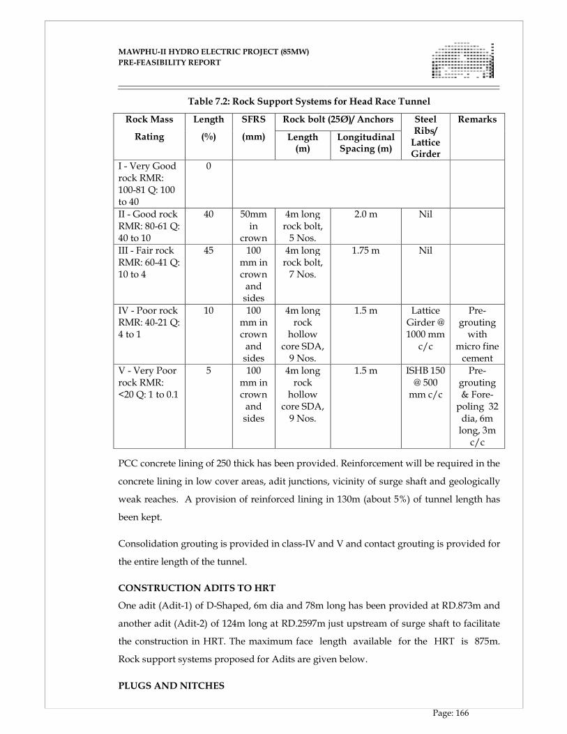
MAWPHU-II HYDRO ELECTRIC PROJECT (85MW)
MAWPHU-II HYDRO ELECTRIC PROJECT (85MW)
PRE-FEASIBILITY REPORT
Page: 166
Table 7.2: Rock Support Systems for Head Race Tunnel
Rock Mass
Rating
Length
(%)
SFRS
(mm)
Rock bolt (25Ø)/ Anchors Steel Ribs/ Lattice Girder
Remarks
Length (m)
Longitudinal Spacing (m)
I - Very Good rock RMR: 100-81 Q: 100 to 40
0
II - Good rock RMR: 80-61 Q: 40 to 10
40 50mm in
crown
4m long rock bolt, 5 Nos.
2.0 m Nil
III - Fair rock RMR: 60-41 Q: 10 to 4
45 100 mm in crown and sides
4m long rock bolt, 7 Nos.
1.75 m Nil
IV - Poor rock RMR: 40-21 Q: 4 to 1
10 100 mm in crown and sides
4m long rock hollow core SDA, 9 Nos.
1.5 m Lattice Girder @ 1000 mm c/c
Pre-grouting with
micro fine cement
V - Very Poor rock RMR: <20 Q: 1 to 0.1
5 100 mm in crown and sides
4m long rock hollow core SDA, 9 Nos.
1.5 m ISHB 150 @ 500 mm c/c
Pre-grouting & Fore- poling 32 dia, 6m long, 3m c/c
PCC concrete lining of 250 thick has been provided. Reinforcement will be required in the
concrete lining in low cover areas, adit junctions, vicinity of surge shaft and geologically
weak reaches. A provision of reinforced lining in 130m (about 5%) of tunnel length has
been kept.
Consolidation grouting is provided in class-IV and V and contact grouting is provided for
the entire length of the tunnel.
CONSTRUCTION ADITS TO HRT
One adit (Adit-1) of D-Shaped, 6m dia and 78m long has been provided at RD.873m and
another adit (Adit-2) of 124m long at RD.2597m just upstream of surge shaft to facilitate
the construction in HRT. The maximum face length available for the HRT is 875m.
Rock support systems proposed for Adits are given below.
PLUGS AND NITCHES
MAWPHU-II HYDRO ELECTRIC PROJECT (85MW)
MAWPHU-II HYDRO ELECTRIC PROJECT (85MW)
PRE-FEASIBILITY REPORT
Page: 167
After completion of all works in HRT, it is proposed to plug all adits with concrete M20.
Plug in Adit-2 which is just upstream of surge shaft is proposed with gate for vehicle
access. Dewatering arrangement has also been provided in the plugs with 300mm pipes.
Contact and consolidation grouting shall be carried out in all the plugs after concreting.
Niches are proposed in the HRT for the convenience of the vehicle crossing and
temporary storage of the materials and these niches will be backfilled with lean concrete.
7.3.7 REQUIREMENT OF SURGE SHAFT
The requirement of the surge shaft is verified based on codal provisions and the
acceleration time of the hydraulic system. The following criteria are usually adopted to
determine whether a surge tank is required for a given hydraulic system.
a) According to codal provision, surge tank is usually necessary if L/H is equal to or
more than 5 to 7, ‘L’ being length of HRT and ‘H’ the net head.
In the case of Mawphu HEP (Stage-II), L=2622m and H = 232m, giving L/H of 11.30.
Consequently, a surge tank is clearly required.
b) Another criterion is based on the acceleration time of the hydraulic system. The
acceleration time (Ta) of a hydraulic system is given by the equation
�� ����
��
Where L = Length of water conductor
V = velocity of flow in water conductor
H = Net head
g = Acceleration due to gravity
If the acceleration time of a hydraulic system is less than 2 seconds, no surge shaft is
required in the hydraulic system. For acceleration time between 2 and 5 seconds, surge
tank may be provided for a stable operation of the system. For acceleration time greater
than 5 sec, a surge tank is almost always required.
In the present case, L = 2622 m, H = 232 m and V = 2.14 m/s which gives an acceleration
time, Ta of 2.47 seconds and hence there is a requirement for a surge tank.
The surge shaft would also help in supplying water to turbines in case of sudden start up
of a machine.
MAWPHU-II HYDRO ELECTRIC PROJECT (85MW)
MAWPHU-II HYDRO ELECTRIC PROJECT (85MW)
PRE-FEASIBILITY REPORT
Page: 168
In view of above, it is proposed to provide a surge shaft.
SELECTION OF THE TYPE OF SURGE SHAFT
Many different types of surge shaft have been developed and the most common among
them are
� Simple Surge Tank
� Orifice type Surge Tank
SIMPLE SURGE TANKS
These tanks are simpler to construct but have large oscillations compared to other type of
tanks. Therefore, the required height will be large. Besides, the oscillations take a long
time in dying out due to slow damping and therefore may remain relatively unstable.
ORIFICE TYPE SURGE TANKS
In this type, tank is connected to HRT through an orifice. When there is sudden injection
of load, the water flows into the tank through the orifice creating an instant high pressure
under the orifice slab. The rise in pressure helps in damping of the oscillations. The
oscillations have shorter amplitude as compared with simple surge tank. The orifice
type tanks are lesser in height for the same size of simple tank. The oscillations die out
rather quickly. This is the main advantage of having orifice type tanks.
Therefore, in Mawphu HEP (Stage-II), out of above two types of surge tanks, orifice type
tank, being advantageous compared to simple tank, is provided.
HYDRAULIC DESIGN OF SURGE SHAFT
Hydraulic design of the surge shaft has been carried out as per IS 7396 (Part-1)-1985. To
ensure the hydraulic stability of surge tank, its minimum area has been calculated
according to Thoma criteria as mentioned below.
Asth���
� ���
A factor of safety of 1.60 has been considered as per IS: 7396 (Part-1) 1985, which yields
an area of 16.12 m2 equivalent to 4.53m dia. Accordingly, a 10.0m dia surge shaft has been
provided.
Transient conditions have been analyzed using the computer program 'WHAMO' (Water
Hammer and Mass Oscillation) developed by US Army Corps of Engineers.
MAWPHU-II HYDRO ELECTRIC PROJECT (85MW)
MAWPHU-II HYDRO ELECTRIC PROJECT (85MW)
PRE-FEASIBILITY REPORT
Page: 169
WHAMO provides dynamic simulation application of fluid distribution systems in hydro
power plants.
The transient analysis has been carried out to determine the maximum upsurge and
down surge levels in the surge tank with respect to different loading/unloading of
generating units corresponding to load acceptance and load rejection conditions when
reservoir is at FRL (EL. 470 m) and at MDDL (EL. 460 m).
The surge levels have been computed with respect to the 100% load rejection and
acceptance and various other combinations of specified load acceptance and rejection to
arrive at the maximum and minimum water levels anticipated in the surge shaft, under
worst conditions as per IS: 7396.
Considering a free board of 3.0 m, top of the surge shaft is kept at EL. 492.00 m MSL and
adequate water cushion below the minimum down surge level, bottom of the surge shaft
at EL. 438.00 m MSL. The diameter of orifice is adopted as 2.80 m.
GEOLOGICAL AND GEO-TECHNICAL ASPECTS FOR SURGE SHAFT
10 m dia surge shaft has been proposed to be excavated after removing the overburden of
27m and 15.16m of rock, the top of the surge shaft from where sinking will start is at El
492m where as rock is encountered at El 507.16. For open excavation, initially about 10m
of overburden excavation shall be in silty soil and would be followed by slope was
material characterized by medium sized angular to sub-angular rock blocks/ fragments
with silty matrix till El 507m.
The overburden slopes mentioned above would contain rock blocks of partially
disintegrated rock confined within a clayey matrix. While excavating these zones
instability is anticipated to get initiated, especially when the material will be saturated.
As such the dressed slopes need to be provided with suitable drainage and soil anchors
for stability.
From El 507m to El 492m i.e. top of the surge shaft, the excavation shall be in moderately
strong, moderately to highly weathered granite gneiss with biotite schist banding. As no
major shear zone was encountered during drilling as such no serious difficulty during the
excavation of shaft is anticipated. In general there is an improvement in rock strength,
weathering and opening of the joints with the depth barring few exceptions at El.491m,
MAWPHU-II HYDRO ELECTRIC PROJECT (85MW)
MAWPHU-II HYDRO ELECTRIC PROJECT (85MW)
PRE-FEASIBILITY REPORT
Page: 170
El.482m, El.472m, El.451m and El.436m where RQD has been found to be low though the
recovery remains constantly high. In such area provision of consolidation grouting shall
be required for ground improvement.
Considering the nature of rock encountered in drill holes and observed rock mechanic
parameters, it is anticipated that the major part of Surge shaft shall negotiate fair to good
rock with occasional patches of poor rock. The suitable rock support consists of rock
bolts, SFRS and pressure relief holes shall be installed concurrent to excavation.
It is assessed that in the initial and terminal part of the surge shaft excavation would
require circular steel set tied firmly to each other along periphery with back fill concrete
in view of the observed weakness especially in these two areas.
SUPPORT SYSTEM
The support system consists of rock bolts and SFRS. In the class-IV and V regions, steel
ribs and pre-grouting with micro-fine cement may be required.
7.3.8 PRESSURE SHAFT
A pressure shaft of size 3.5 m dia and 869m long (main shaft) is proposed downstream of
surge shaft. Pressure shaft drops vertically from El. 433.40m to El. 291.50m. The bottom
horizontal pressure shaft is provided with a slope of 1 in 12 from El.291.50m up to
El.227m in line with the center line of unit.
Main pressure shaft bifurcates into 2.50m dia and 32m long branch pressure shafts to feed
two turbine units in the power house. The size of the pressure shaft has been arrived
based on the detailed economic studies.
The diameter of the branch pressure shafts have been fixed in such a way that the
velocity is in line with the main pressure shaft. Velocity through pressure shaft works
out to around 4.42m/sec.
Considering thick overburden and vertical bends throughout the surface alignment,
underground pressure shaft is proposed. Two alternatives, one, connecting the top and
bottom horizontal pressure shaft with an inclined shaft and another, connecting the two
with a vertical shaft were examined. It was found that the length of the bottom horizontal
pressure shaft is relatively less with an inclined shaft and is suitable from economic
MAWPHU-II HYDRO ELECTRIC PROJECT (85MW)
MAWPHU-II HYDRO ELECTRIC PROJECT (85MW)
PRE-FEASIBILITY REPORT
Page: 171
considerations. However, from construction point of view, as vertical pressure shaft
is preferable, the same is proposed.
GEOLOGICAL AND GEO-TECHNICAL ASPECTS
For top horizontal pressure shaft, the alignment pass through rock with superincumbent
cover including overburden varying from 84m near top bend to 110m near surge shaft.
However, rock cover above horizontal pressure shaft varies from 57m (El. 490.5m) near
bend to 74m (El. 507.36m) near surge shaft. The subsurface information from exploration
and results of rock mechanic test indicate sufficient suitable rock cover over the
structure exists in this part of pressure shaft and is anticipated to negotiate
generally fair to good rock with patches of very good and poor to very poor rock class as
20% in class-II, 70% in class-III, 5% in class-IV and 5% in class-V.
The vertical pressure shaft shall pass through rock with superincumbent cover including
overburden of 84m near top bend of pressure shaft EL. 490.5m. The subsurface
information from exploration and results of rock mechanic tests indicate that
sufficient and suitable vertical as well as lateral rock cover exist around vertical pressure
shaft and is anticipated to negotiate generally fair to good rock with occasional weak
features.
The bottom horizontal pressure shaft shall pass through rock with superincumbent cover
including overburden varying from 230m near vertical pressure shaft side to 72m near
power house side. For the first 540m of bottom pressure shaft, rock cover above structure
can be varying between 37m (El. 272.5 m) near power house and 205.9 m (El. 480.7m)
near vertical pressure shaft. The subsurface information from exploration and results of
rock mechanics test indicate that sufficient rock cover exists over the structure and
bottom horizontal pressure shaft is anticipated to negotiate generally very good
rock with intermediate length of fair and patches of poor to very poor rock class as 68%
in class-II, 25% in class-III, 5% in class-IV and 2% in class-V for the first 540m length and
20% in class- II, 65% in class-III, 10% in class-IV and 5% in class-V.
ROCK SUPPORT SYSTEM FOR PRESSURE SHAFT
The Pressure Shaft will negotiate different rock types of variable strength with different
tunneling conditions along its length ranging from good rock to very poor rock. The
tunnel excavation will be done by drill and blast method with full face excavation.
MAWPHU-II HYDRO ELECTRIC PROJECT (85MW)
MAWPHU-II HYDRO ELECTRIC PROJECT (85MW)
PRE-FEASIBILITY REPORT
Page: 172
In order to design the initial support system for the tunnel, the rock mass along the
tunnel was categorized into five groups based on RMR values/Q values, and the support
system for each group as mentioned in the below table was designed for both main
pressure shaft and branch pressure shaft.
The supporting system comprises of rock bolts, SFRS and steel ribs as mentioned in the
below Table 7.3. In the class-IV and V zones, pre-grouting with microfine cement may be
required. Forepoling, will be resorted as per requirement while boring in class V type of
rock. Probe drilling shall be resorted for identifying the problem areas and suitable prior
remedial measure shall be kept ready before hand.
Table 7.3 Rock Support Systems
Main Pressure Shaft
Rock Mass
Rating
Length
(%)
SFRS
(mm)
Rock bolt (25Ø)/ Anchors Steel Ribs/ Lattice Girder
Remarks
Length (m)
Longitudinal Spacing (m)
I - Very Good rock RMR: 100-81 Q: 100 to 40
0 Generally no support required except spot
bolting and SFRS at local region.
II - Good rock RMR: 80-61 Q: 40 to 10
60 50mm in
crown
2.5m long rock bolt, 5 Nos.
2.0 m Nil
III - Fair rock RMR: 60-41 Q: 10 to 4
30 100 mm in crown and sides
2.5m long rock bolt, 7 Nos.
1.75 m Nil
IV - Poor rock RMR: 40-21 Q: 4 to 1
6 100 mm in crown and sides
2.5m long rock hollow core SDA, 9 Nos.
1.5 m Lattice Girder @ 1000 mm c/c
Pre-grouting with
micro fine cement
V - Very Poor rock RMR: <20 Q: 1 to 0.1
4 100 mm in crown and sides
2.5m long rock hollow core SDA, 9 Nos.
1.5 m ISMB 200 @ 500 mm c/c
Pre-grouting & Fore- poling 32 dia, 6m long, 3m c/c
Branch Pressure Shaft
I - Very Good rock RMR: 100-81
0 Generally no support required except spot
bolting and SFRS at local region.
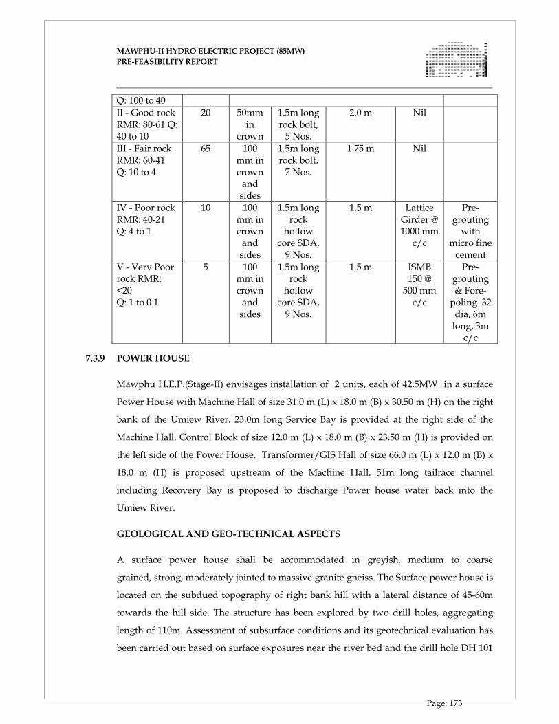
MAWPHU-II HYDRO ELECTRIC PROJECT (85MW)
MAWPHU-II HYDRO ELECTRIC PROJECT (85MW)
PRE-FEASIBILITY REPORT
Page: 173
Q: 100 to 40
II - Good rock RMR: 80-61 Q: 40 to 10
20 50mm in
crown
1.5m long rock bolt, 5 Nos.
2.0 m Nil
III - Fair rock RMR: 60-41 Q: 10 to 4
65 100 mm in crown and sides
1.5m long rock bolt, 7 Nos.
1.75 m Nil
IV - Poor rock RMR: 40-21 Q: 4 to 1
10 100 mm in crown and sides
1.5m long rock hollow core SDA, 9 Nos.
1.5 m Lattice Girder @ 1000 mm c/c
Pre-grouting with
micro fine cement
V - Very Poor rock RMR: <20 Q: 1 to 0.1
5 100 mm in crown and sides
1.5m long rock hollow core SDA, 9 Nos.
1.5 m ISMB 150 @ 500 mm c/c
Pre-grouting & Fore- poling 32 dia, 6m long, 3m c/c
7.3.9 POWER HOUSE
Mawphu H.E.P.(Stage-II) envisages installation of 2 units, each of 42.5MW in a surface
Power House with Machine Hall of size 31.0 m (L) x 18.0 m (B) x 30.50 m (H) on the right
bank of the Umiew River. 23.0m long Service Bay is provided at the right side of the
Machine Hall. Control Block of size 12.0 m (L) x 18.0 m (B) x 23.50 m (H) is provided on
the left side of the Power House. Transformer/GIS Hall of size 66.0 m (L) x 12.0 m (B) x
18.0 m (H) is proposed upstream of the Machine Hall. 51m long tailrace channel
including Recovery Bay is proposed to discharge Power house water back into the
Umiew River.
GEOLOGICAL AND GEO-TECHNICAL ASPECTS
A surface power house shall be accommodated in greyish, medium to coarse
grained, strong, moderately jointed to massive granite gneiss. The Surface power house is
located on the subdued topography of right bank hill with a lateral distance of 45-60m
towards the hill side. The structure has been explored by two drill holes, aggregating
length of 110m. Assessment of subsurface conditions and its geotechnical evaluation has
been carried out based on surface exposures near the river bed and the drill hole DH 101
MAWPHU-II HYDRO ELECTRIC PROJECT (85MW)
MAWPHU-II HYDRO ELECTRIC PROJECT (85MW)
PRE-FEASIBILITY REPORT
Page: 174
and DH-102. The long axis of surface power has been oriented in N119°direction i.e.
perpendicular to prominent strike of foliation (N028°-N208).
Two geological sections have been developed w.r.t the power house for better appraisal
of geological and geotechnical conditions. It is evident from these section that height of
cutting in the rock will around 38m whereas in overburden it will be of the order
of 45- 50m.Coefficeint of permeability in overburden ranges from 0.29X10⁻³cm/sec to
2X10⁻³cm/sec which indicate highly pervious nature of overburden. Since overburden is
of river borne material indicative of a pre-existing river terrace, presence of water table at
a depth of 12 - 14m will make this material more susceptible to instability. Accordingly in
view of very high rainfall, the project area receives, elaborate and effective slope
stabilization measure to avoid surcharging of the overburden and erosion of slope
due to storm water shall be adopted to maintain long term stability of the cut slope.
Surface power house has been placed suitably with respect to strike of foliation. However
in view of sub parallelism of width wise excavation line of service bay viz-a –viz. the
strike of foliation and dip of foliation being towards excavation, plane failure is
anticipated. In view of the same notwithstanding the limited cutting at service bay
section appropriate support measures needs to be kept in provision which would include
6m long rock bolts with spacing of 2 to 3m.
Apart from this foliation, S2(030/71) joint set striking almost parallel to the power house
alignment ,dipping steeply from upstream wall of power house towards the power house
pit and has the potential to create unstable wedge due to toppling effect in the upstream
wall. The set combining with other limiting planes would generate plane failure on the
downstream wall of Power house. Accordingly necessary support measure should be
kept in provision of suitable length of rock bolt, SFRS and pressure relieve
arrangement. In view of predominance of adversely oriented joints enhancement of
support in the form of longer rock bolts exceeding 6m may have to be installed in the top
one third portion of rock slope. However the same shall be decided during the
progressive excavation of the pit.
As can be seen from slope stability analysis for back slope, set S2 (030/71) is seem to
contribute in formation of unstable wedges by topple failure which have a tendency to
fail toward the valley side or into the excavation. Apart from this toppling failure sliding
MAWPHU-II HYDRO ELECTRIC PROJECT (85MW)
MAWPHU-II HYDRO ELECTRIC PROJECT (85MW)
PRE-FEASIBILITY REPORT
Page: 175
wedge failure also expected to be occur for the given cut slope by intersection of the joint
set S4(172/80) and joint set S3 (261/78) in which sliding direction of wedge is 222/75.
Permeability in rock ranges from 2-5 Lugeon indicating its fairly tight nature
of discontinuities. However, higher Lugeon reported only from the overburden bedrock
interface or from the fractured zones. Accordingly pressure relieve arrangement in each
wall of the power house shall be made.
Generally Core recovery in rock vary from 80-95% and RQD vary from 30-80%.In view of
above during excavation in selected weak media consolidation grouting shall be resorted.
However Rock mechanics test conducted on the cores samples from Power House area
reveals the UCS value of 106 to 137 MPa. It is therefore concluded that foundation of the
surface power house shall be in sound rock.
The entire excavation for Power house pit shall be in bedrock having indicative
RMR (without rating adjustment) ranges from 50 To 59 computed on the basis of
geotechnical parameter collected from the outcrops and collating the finding from
boreholes DH-101 and DH-102 in which bedrock was encountered at El 268.6m and
262.2m respectively.
POWER HOUSE CUT SLOPE SUPPORT SYSTEM
Keeping in view of the geology and topography existing there, a flatter slope of 1.5 (H):
1(V) has been proposed for the overburden with slope support measures in the form of
Geo- Textile, Grouted Anchors, low pressure consolidation grouting and Drainage holes
with filters for relieving the hydrostatic pressure. Berms with a height of 10m have also
been proposed which will not only serve the purpose of stabilizing the Power House cut
slope but also facilitate the excavation activities during construction. Berms width is kept
as 5m including drain. Toe drains of 500mmx500m with 1 in 500 slopes have also been
planned to collect and discharge the rain water to a suitable location. Cut slope of 1 (H):
6(V) has been planned for the rocky starta with adequate slope support in the form of
SFRS, Anchor bolts and Drainage holes with filters.
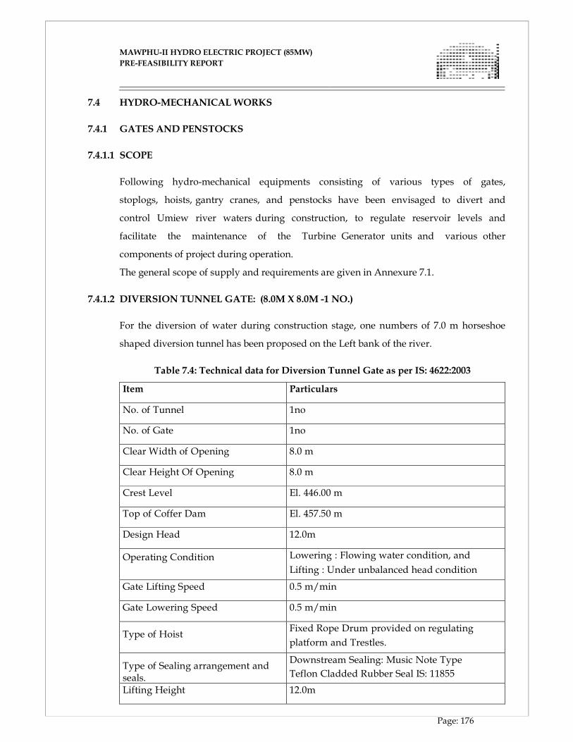
MAWPHU-II HYDRO ELECTRIC PROJECT (85MW)
MAWPHU-II HYDRO ELECTRIC PROJECT (85MW)
PRE-FEASIBILITY REPORT
Page: 176
7.4 HYDRO-MECHANICAL WORKS
7.4.1 GATES AND PENSTOCKS
7.4.1.1 SCOPE
Following hydro-mechanical equipments consisting of various types of gates,
stoplogs, hoists, gantry cranes, and penstocks have been envisaged to divert and
control Umiew river waters during construction, to regulate reservoir levels and
facilitate the maintenance of the Turbine Generator units and various other
components of project during operation.
The general scope of supply and requirements are given in Annexure 7.1.
7.4.1.2 DIVERSION TUNNEL GATE: (8.0M X 8.0M -1 NO.)
For the diversion of water during construction stage, one numbers of 7.0 m horseshoe
shaped diversion tunnel has been proposed on the Left bank of the river.
Table 7.4: Technical data for Diversion Tunnel Gate as per IS: 4622:2003
Item Particulars
No. of Tunnel 1no
No. of Gate 1no
Clear Width of Opening 8.0 m
Clear Height Of Opening 8.0 m
Crest Level El. 446.00 m
Top of Coffer Dam El. 457.50 m
Design Head 12.0m
Operating Condition Lowering : Flowing water condition, and
Lifting : Under unbalanced head condition
Gate Lifting Speed 0.5 m/min
Gate Lowering Speed 0.5 m/min
Type of Hoist
Fixed Rope Drum provided on regulating
platform and Trestles.
Type of Sealing arrangement and seals.
Downstream Sealing: Music Note Type
Teflon Cladded Rubber Seal IS: 11855
Lifting Height 12.0m
MAWPHU-II HYDRO ELECTRIC PROJECT (85MW)
MAWPHU-II HYDRO ELECTRIC PROJECT (85MW)
PRE-FEASIBILITY REPORT
Page: 177
For 7.0 m horseshoe shaped diversion tunnel one gate of size 8.0m x 8.0m is proposed at
the inlet portals to facilitate regulation during diversion and plugging before
commissioning of the project. This gate is provided with individual rope drum hoist and
designed as fixed wheel type gate having downstream skin plate and downstream
sealing. The sill level of gate is kept at EL.446.00m and the gate is to be designed for a
head of 12.0m corresponding to Top of coffer dam level El. 457.50m plus projected
overflow depth.
On the other hand hoist capacity of the gates is determined for their operation during
diversion and shall be calculated for water head corresponding to Cofferdam top level of
El. 457.50m.
The gate shall be operated by means of electrically operated rope drum hoist of adequate
capacity, located on the hoist platform installed over trestles above deck level, EL.
457.50m.
7.4.1.3 STOPLOGS FOR SLUICE SPILLWAY RADIAL GATES: (8.0M X 16.2M – 1SET)
For the passing of the water downstream for maintaining reservoir level 5 Nos.
Sluice Spillway Radial gates of 8.0m x 11.5m have been envisaged.
Stoplog units shall be required to be lowered in the stoplog groove of a particular bay, the
radial gate of which is under inspection/maintenance. The stoplogs shall be lowered
under flowing water conditions and lifted under balanced head condition. Inspection,
maintenance and repairs of radial gate shall be planned to be started and completed
preferably in lean period. Each stop log unit shall be self closing i.e. by gravity under its
own weight. The stoplog units shall be handled by a gantry crane of adequate capacity.
For the maintenance of 5 numbers of Sluice Spillway Radial gates, one sets of stoplogs,
each set consisting of 7 units of size 8.0m x 2.32m shall be provided.
Table 7.5: Technical data for Sluice Spillway Radial Gates as per IS: 4622:2003
Item Particulars
No of Opening 4.0
No of Sets 1(Each set consists of 5 interchangeable units,
1 top unit and 1 bottom unit each of size 7.0
m x 2.32m)
MAWPHU-II HYDRO ELECTRIC PROJECT (85MW)
MAWPHU-II HYDRO ELECTRIC PROJECT (85MW)
PRE-FEASIBILITY REPORT
Page: 178
Clear Width of Opening 8.0 m
Clear Height Of Opening 16.2m
Sill Level of stoplogs El. 442.81m
F.R.L El. 470.00m
Design Head 27.19m
Top of Dam El. 472.00m
Operating Condition Lowering : Flowing water condition, and
Lifting : Top unit shall be crack opened to
achieve balanced head condition
Type of Hoist Gantry Crane
Lifting Speed 0.75 m/min
Lowering Speed 0.75 m/min
Type of Sealing arrangement and seals.
Downstream Sealing: Music Note Type
Teflon Cladded Rubber Seal IS: 11855
Lifting Height 31.5m
Automatic engaging and disengaging
Lifting Beam
1 No.
When not in use the stop logs shall be stored on latches in the grooves above
FRL and one stoplog storage bay provided on Dam Block No.3. One number
automatically engaging and disengaging lifting beam shall be provided to facilitate
operation of the stoplogs with the help of gantry crane.
The stop log units for Sluice Spillway Radial gates shall be of fabricated steel construction
with upstream skin plate and downstream sealing. The units shall be capable of use in
any of the 5 openings. The stop log units shall normally be lowered in flowing water
condition and lifted in balanced head conditions when water level is at Full Reservoir
Level El. 470.00m or below it. All the stop log units except the top unit having top seal
shall be inter-changeable.
On the other hand hoist capacity of the stoplogs is determined for their operation during
maintenance of radial gates and shall be calculated for water head corresponding to FRL
El.470.00m.
MAWPHU-II HYDRO ELECTRIC PROJECT (85MW)
MAWPHU-II HYDRO ELECTRIC PROJECT (85MW)
PRE-FEASIBILITY REPORT
Page: 179
7.4.1.4 SLUICE SPILLWAY RADIAL GATES: (8.0M X 11.5M - 5NOS.)
All the gates shall be operated with hydraulic hoists of adequate capacity and shall be
designed to regulate discharge under design heads and flow conditions mentioned herein
after:
The Sluice spillway radial gates shall normally remain in closed position during power
generation. When the water level in the reservoir starts rising above the Full Reservoir
Level i.e. EL 470.00m the FRL will be maintained by operating these gates.
The Sluice spillway radial gates shall also be operated to flush out the deposited silt
during the periods of heavy discharges. Since there would be lot of abrasion due to high
velocity water flow carrying silt load, it is proposed to provide skin plate of
stainless steel conforming to AISI 420 grade steel. Also, the spillway profile
downstream of radial gates shall be steel lined upto height of 1m higher than max.
discharge nape.
Table 7.6: Technical data for Sluice Spillway Radial Gates as per IS: 4623:2000
Item Particulars
No of Opening 5 Nos.
No of Gates 5 Nos.
Clear Width of Opening 8.0m
Clear Height Of Opening 11.5m
Radius of Gate 14.0m
C/C of Trunion Level EL. 455.80m
Sill level EL. 443.90m
Top of Dam EL. 472.00m
F.R.L El. 470.00m
Design Head 26.1m
Operating Condition Lowering : Flowing water condition, and
Lifting : Under unbalanced head condition
Gate Lifting Speed 0.50 m/min
MAWPHU-II HYDRO ELECTRIC PROJECT (85MW)
MAWPHU-II HYDRO ELECTRIC PROJECT (85MW)
PRE-FEASIBILITY REPORT
Page: 180
Gate Lowering Speed 0.50 m/min; 0.15m/min for last 30 cm
travels.
Lifting Height 12.0m
Type of Hoist Hydraulic Hoists
The crest of gate has been kept at El. 443.90m. The radial gates will be operated by an
individual hydraulic hoists of adequate capacity; consisting of power pack and shall have
twin hydraulic cylinders one on each side of the gate. The gates shall be operated locally
with a power pack from the control room, which would be located on top of the dam in a
room. The hydraulic cylinder hanging bracket elevation is kept at EL. 461.01m. The
cylinder shall be connects on downstream of the skin plate. The power pack shall have
provision to operate gate of adjacent bays. The trunnion shall be located at EL. 455.80m
such that it is at least 1.5 m higher than the nape.
The minimum speeds of travel of ate shall be: for opening 0.50 m/min., for lowering
0.50m/min., for last 30 cm travels in lowering 0.15 m/min.
To limit the sway of the gate during operation, guide rollers shall be provided on each
side of the gate. Each radial gate trunnion support beam shall be suitably anchored to the
pier. The gate shall be provided with dogging devices to hold the gate in fully raised
position when the hoist is disconnected from the gate during maintenance. These radial
gates shall be designed in accordance with IS: 4623: 2000 recommendations.
The gates shall have Teflon cladded side and top seals and wedge type rubber bottom
seal. The seals shall be designed and constructed as per IS: 11855: 2004 and IS 15466: 2004.
7.4.1.5 INTAKE TRASH RACKS (5.0M X 2.0M -2SETS/20 PANELS)
The trash racks shall be required to be installed in the trash rack grooves of Intake
structure U/S of Emergency gate groove to prevent entry of extraneous material into the
water conductor system. These shall be of fabricated steel construction consisting of trash
bars supported on horizontal girders, which in turn shall be supported on end
channels/members to bear against the downstream face of slots. Trash racks for one
opening shall be split into two vents each and each vent consists of 10 panels of 5.0m
width and 2.0m height. The trash rack sill is kept at El.452.00m and shall be provided up
to the top of intake for cleaning with trash cleaning machine.
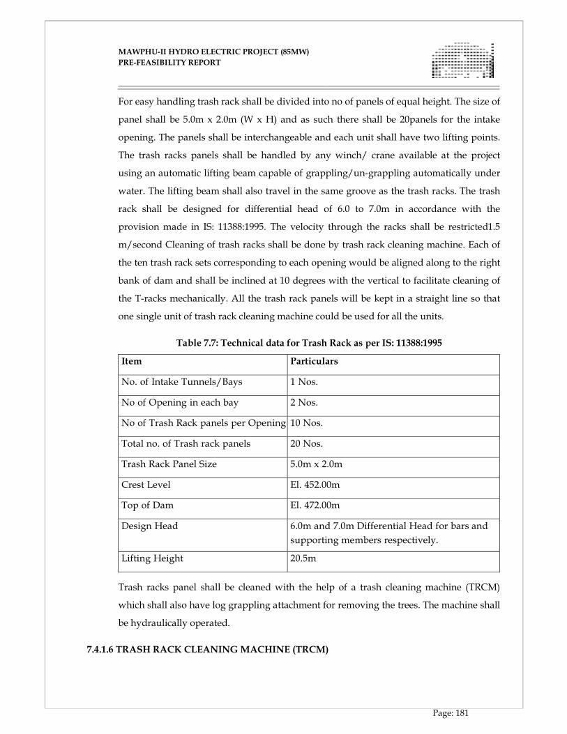
MAWPHU-II HYDRO ELECTRIC PROJECT (85MW)
MAWPHU-II HYDRO ELECTRIC PROJECT (85MW)
PRE-FEASIBILITY REPORT
Page: 181
For easy handling trash rack shall be divided into no of panels of equal height. The size of
panel shall be 5.0m x 2.0m (W x H) and as such there shall be 20panels for the intake
opening. The panels shall be interchangeable and each unit shall have two lifting points.
The trash racks panels shall be handled by any winch/ crane available at the project
using an automatic lifting beam capable of grappling/un-grappling automatically under
water. The lifting beam shall also travel in the same groove as the trash racks. The trash
rack shall be designed for differential head of 6.0 to 7.0m in accordance with the
provision made in IS: 11388:1995. The velocity through the racks shall be restricted1.5
m/second Cleaning of trash racks shall be done by trash rack cleaning machine. Each of
the ten trash rack sets corresponding to each opening would be aligned along to the right
bank of dam and shall be inclined at 10 degrees with the vertical to facilitate cleaning of
the T-racks mechanically. All the trash rack panels will be kept in a straight line so that
one single unit of trash rack cleaning machine could be used for all the units.
Table 7.7: Technical data for Trash Rack as per IS: 11388:1995
Item Particulars
No. of Intake Tunnels/Bays 1 Nos.
No of Opening in each bay 2 Nos.
No of Trash Rack panels per Opening 10 Nos.
Total no. of Trash rack panels 20 Nos.
Trash Rack Panel Size 5.0m x 2.0m
Crest Level El. 452.00m
Top of Dam El. 472.00m
Design Head 6.0m and 7.0m Differential Head for bars and
supporting members respectively.
Lifting Height 20.5m
Trash racks panel shall be cleaned with the help of a trash cleaning machine (TRCM)
which shall also have log grappling attachment for removing the trees. The machine shall
be hydraulically operated.
7.4.1.6 TRASH RACK CLEANING MACHINE (TRCM)
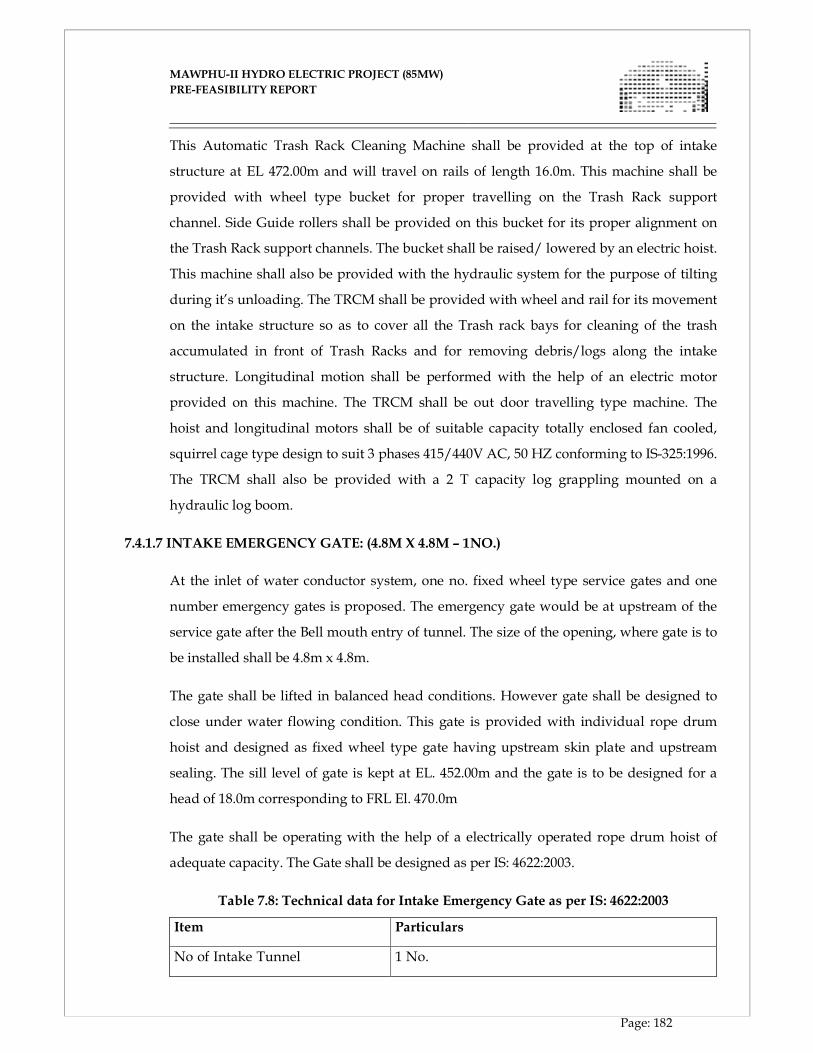
MAWPHU-II HYDRO ELECTRIC PROJECT (85MW)
MAWPHU-II HYDRO ELECTRIC PROJECT (85MW)
PRE-FEASIBILITY REPORT
Page: 182
This Automatic Trash Rack Cleaning Machine shall be provided at the top of intake
structure at EL 472.00m and will travel on rails of length 16.0m. This machine shall be
provided with wheel type bucket for proper travelling on the Trash Rack support
channel. Side Guide rollers shall be provided on this bucket for its proper alignment on
the Trash Rack support channels. The bucket shall be raised/ lowered by an electric hoist.
This machine shall also be provided with the hydraulic system for the purpose of tilting
during it’s unloading. The TRCM shall be provided with wheel and rail for its movement
on the intake structure so as to cover all the Trash rack bays for cleaning of the trash
accumulated in front of Trash Racks and for removing debris/logs along the intake
structure. Longitudinal motion shall be performed with the help of an electric motor
provided on this machine. The TRCM shall be out door travelling type machine. The
hoist and longitudinal motors shall be of suitable capacity totally enclosed fan cooled,
squirrel cage type design to suit 3 phases 415/440V AC, 50 HZ conforming to IS-325:1996.
The TRCM shall also be provided with a 2 T capacity log grappling mounted on a
hydraulic log boom.
7.4.1.7 INTAKE EMERGENCY GATE: (4.8M X 4.8M – 1NO.)
At the inlet of water conductor system, one no. fixed wheel type service gates and one
number emergency gates is proposed. The emergency gate would be at upstream of the
service gate after the Bell mouth entry of tunnel. The size of the opening, where gate is to
be installed shall be 4.8m x 4.8m.
The gate shall be lifted in balanced head conditions. However gate shall be designed to
close under water flowing condition. This gate is provided with individual rope drum
hoist and designed as fixed wheel type gate having upstream skin plate and upstream
sealing. The sill level of gate is kept at EL. 452.00m and the gate is to be designed for a
head of 18.0m corresponding to FRL El. 470.0m
The gate shall be operating with the help of a electrically operated rope drum hoist of
adequate capacity. The Gate shall be designed as per IS: 4622:2003.
Table 7.8: Technical data for Intake Emergency Gate as per IS: 4622:2003
Item Particulars
No of Intake Tunnel 1 No.
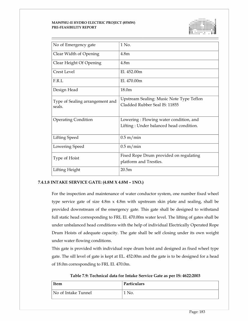
MAWPHU-II HYDRO ELECTRIC PROJECT (85MW)
MAWPHU-II HYDRO ELECTRIC PROJECT (85MW)
PRE-FEASIBILITY REPORT
Page: 183
No of Emergency gate 1 No.
Clear Width of Opening 4.8m
Clear Height Of Opening 4.8m
Crest Level El. 452.00m
F.R.L El. 470.00m
Design Head 18.0m
Type of Sealing arrangement and seals.
Upstream Sealing: Music Note Type Teflon
Cladded Rubber Seal IS: 11855
Operating Condition Lowering : Flowing water condition, and
Lifting : Under balanced head condition.
Lifting Speed 0.5 m/min
Lowering Speed 0.5 m/min
Type of Hoist
Fixed Rope Drum provided on regulating
platform and Trestles.
Lifting Height 20.5m
7.4.1.8 INTAKE SERVICE GATE: (4.8M X 4.8M – 1NO.)
For the inspection and maintenance of water conductor system, one number fixed wheel
type service gate of size 4.8m x 4.8m with upstream skin plate and sealing, shall be
provided downstream of the emergency gate. This gate shall be designed to withstand
full static head corresponding to FRL El. 470.00m water level. The lifting of gates shall be
under unbalanced head conditions with the help of individual Electrically Operated Rope
Drum Hoists of adequate capacity. The gate shall be self closing under its own weight
under water flowing conditions.
This gate is provided with individual rope drum hoist and designed as fixed wheel type
gate. The sill level of gate is kept at EL. 452.00m and the gate is to be designed for a head
of 18.0m corresponding to FRL El. 470.0m.
Table 7.9: Technical data for Intake Service Gate as per IS: 4622:2003
Item Particulars
No of Intake Tunnel 1 No.
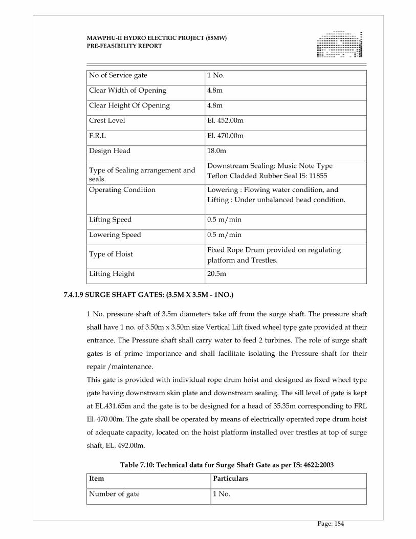
MAWPHU-II HYDRO ELECTRIC PROJECT (85MW)
MAWPHU-II HYDRO ELECTRIC PROJECT (85MW)
PRE-FEASIBILITY REPORT
Page: 184
No of Service gate 1 No.
Clear Width of Opening 4.8m
Clear Height Of Opening 4.8m
Crest Level El. 452.00m
F.R.L El. 470.00m
Design Head 18.0m
Type of Sealing arrangement and seals.
Downstream Sealing: Music Note Type
Teflon Cladded Rubber Seal IS: 11855
Operating Condition Lowering : Flowing water condition, and
Lifting : Under unbalanced head condition.
Lifting Speed 0.5 m/min
Lowering Speed 0.5 m/min
Type of Hoist
Fixed Rope Drum provided on regulating
platform and Trestles.
Lifting Height 20.5m
7.4.1.9 SURGE SHAFT GATES: (3.5M X 3.5M - 1NO.)
1 No. pressure shaft of 3.5m diameters take off from the surge shaft. The pressure shaft
shall have 1 no. of 3.50m x 3.50m size Vertical Lift fixed wheel type gate provided at their
entrance. The Pressure shaft shall carry water to feed 2 turbines. The role of surge shaft
gates is of prime importance and shall facilitate isolating the Pressure shaft for their
repair /maintenance.
This gate is provided with individual rope drum hoist and designed as fixed wheel type
gate having downstream skin plate and downstream sealing. The sill level of gate is kept
at EL.431.65m and the gate is to be designed for a head of 35.35m corresponding to FRL
El. 470.00m. The gate shall be operated by means of electrically operated rope drum hoist
of adequate capacity, located on the hoist platform installed over trestles at top of surge
shaft, EL. 492.00m.
Table 7.10: Technical data for Surge Shaft Gate as per IS: 4622:2003
Item Particulars
Number of gate 1 No.
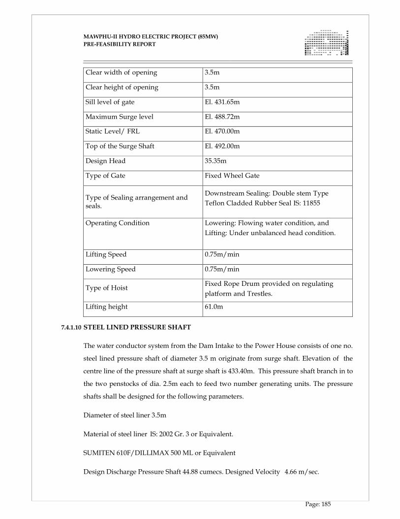
MAWPHU-II HYDRO ELECTRIC PROJECT (85MW)
MAWPHU-II HYDRO ELECTRIC PROJECT (85MW)
PRE-FEASIBILITY REPORT
Page: 185
Clear width of opening 3.5m
Clear height of opening 3.5m
Sill level of gate El. 431.65m
Maximum Surge level El. 488.72m
Static Level/ FRL El. 470.00m
Top of the Surge Shaft El. 492.00m
Design Head 35.35m
Type of Gate Fixed Wheel Gate
Type of Sealing arrangement and seals.
Downstream Sealing: Double stem Type
Teflon Cladded Rubber Seal IS: 11855
Operating Condition Lowering: Flowing water condition, and
Lifting: Under unbalanced head condition.
Lifting Speed 0.75m/min
Lowering Speed 0.75m/min
Type of Hoist
Fixed Rope Drum provided on regulating
platform and Trestles.
Lifting height 61.0m
7.4.1.10 STEEL LINED PRESSURE SHAFT
The water conductor system from the Dam Intake to the Power House consists of one no.
steel lined pressure shaft of diameter 3.5 m originate from surge shaft. Elevation of the
centre line of the pressure shaft at surge shaft is 433.40m. This pressure shaft branch in to
the two penstocks of dia. 2.5m each to feed two number generating units. The pressure
shafts shall be designed for the following parameters.
Diameter of steel liner 3.5m
Material of steel liner IS: 2002 Gr. 3 or Equivalent.
SUMITEN 610F/DILLIMAX 500 ML or Equivalent
Design Discharge Pressure Shaft 44.88 cumecs. Designed Velocity 4.66 m/sec.
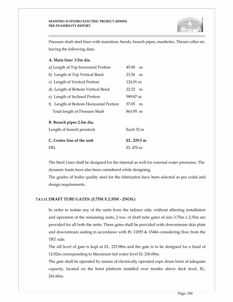
MAWPHU-II HYDRO ELECTRIC PROJECT (85MW)
MAWPHU-II HYDRO ELECTRIC PROJECT (85MW)
PRE-FEASIBILITY REPORT
Page: 186
Pressure shaft steel liner with transition, bends, branch pipes, manholes, Thrust collar etc.
having the following data:
A. Main liner 3.5m dia.
a) Length of Top horizontal Portion 45.00 m
b) Length of Top Vertical Bend 23.56 m
c) Length of Vertical Portion 124.91 m
d). Length of Bottom Vertical Bend 22.32 m
e) Length of Inclined Portion 589.87 m
f) Length of Bottom Horizontal Portion 57.05 m
Total length of Pressure Shaft 863.95 m
B. Branch pipes 2.5m dia.
Length of branch penstock Each 32 m
C. Centre line of the unit EL. 229.5 m
FRL EL 470 m
The Steel Liner shall be designed for the internal as well for external water pressures. The
dynamic loads have also been considered while designing.
The grades of boiler quality steel for the fabrication have been selected as per codal and
design requirements.
7.4.1.11 DRAFT TUBE GATES: (3.75M X 2.35M - 2NOS.)
In order to isolate any of the units from the tailrace side, without affecting installation
and operation of the remaining units, 2 nos. of draft tube gates of size 3.75m x 2.35m are
provided for all both the units. These gates shall be provided with downstream skin plate
and downstream sealing in accordance with IS: 11855 & 15466 considering flow from the
TRT side.
The sill level of gate is kept at EL. 223.98m and the gate is to be designed for a head of
12.02m corresponding to Maximum tail water level El. 236.00m.
The gate shall be operated by means of electrically operated rope drum hoist of adequate
capacity, located on the hoist platform installed over trestles above deck level, EL.
241.60m.
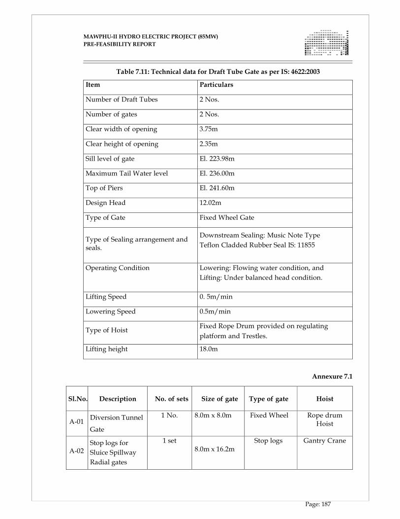
MAWPHU-II HYDRO ELECTRIC PROJECT (85MW)
MAWPHU-II HYDRO ELECTRIC PROJECT (85MW)
PRE-FEASIBILITY REPORT
Page: 187
Table 7.11: Technical data for Draft Tube Gate as per IS: 4622:2003
Item Particulars
Number of Draft Tubes 2 Nos.
Number of gates 2 Nos.
Clear width of opening 3.75m
Clear height of opening 2.35m
Sill level of gate El. 223.98m
Maximum Tail Water level El. 236.00m
Top of Piers El. 241.60m
Design Head 12.02m
Type of Gate Fixed Wheel Gate
Type of Sealing arrangement and seals.
Downstream Sealing: Music Note Type
Teflon Cladded Rubber Seal IS: 11855
Operating Condition Lowering: Flowing water condition, and
Lifting: Under balanced head condition.
Lifting Speed 0. 5m/min
Lowering Speed 0.5m/min
Type of Hoist
Fixed Rope Drum provided on regulating
platform and Trestles.
Lifting height 18.0m
Annexure 7.1
Sl.No.
Description
No. of sets
Size of gate
Type of gate
Hoist
A-01
Diversion Tunnel
Gate
1 No. 8.0m x 8.0m Fixed Wheel Rope drum Hoist
A-02
Stop logs for
Sluice Spillway
Radial gates
1 set 8.0m x 16.2m
Stop logs Gantry Crane

MAWPHU-II HYDRO ELECTRIC PROJECT (85MW)
MAWPHU-II HYDRO ELECTRIC PROJECT (85MW)
PRE-FEASIBILITY REPORT
Page: 188
A-03
Sluice Spillway
Radial gates
5 Nos. 8.0m x 11.5m Radial Hydraulic Hoist
A-04
Intake Trash
racks
2 sets / 20 pannels
5.0m x 2.0m inclined(10º) TRCM
A-05
Intake
Emergency gate
1 No. 4.8m x 4.8m Fixed Wheel Rope drum Hoist
A-06
Intake service
gate
1 No. 4.8m x 4.8m Fixed Wheel Rope drum Hoist
A-07 Surge shaft gate 1 No. 3.5m x 3.5m
Fixed Wheel Rope drum
Hoist A-08
Main Pressure
Shaft
1 No. Dia=3.5m, Length – 864 m
Branch Penstock 2 Nos. Dia=2.5m, Length – 32 m each
A-09 Draft Tube Gates 2 Nos. 3.75m x 2.35m Fixed Wheel Rope Drum Hoist
CHAPTER - VIII
DESIGN OF ELECTRO-MECHANICAL WORKS
MAWPHU-II HYDRO ELECTRIC PROJECT (85MW)
MAWPHU-II HYDRO ELECTRIC PROJECT (85MW)
PRE-FEASIBILITY REPORT
Page: 189
CHAPTER - VIII
DESIGN OF ELECTRO-MECHANICAL WORKS
8.1 GENERAL
The surface powerhouse shall have two generating units of 42.5MW each with all the
auxiliary facilities such as cooling water system, heating, ventilation and air conditioning
system, fire protection system, oil pressure system, overhead crane system, compressed
air supply system etc. The total generating capacity of power house shall be 85MW.The
entire two units would be identical and comprise of vertical axis Francis turbine directly
coupled with synchronous generator. Power will be generated at 11kv voltage level and
stepped up to 132kv level by generator step up transformer. Both the generating units
will be provided with 10% continuous overload capacity as per CEA grid connectivity
regulations. The Generator step up transformer with 10% overload capacity shall be
provided.
The powerhouse will comprise of the Service Bay, Machine Hall, Generator Floor,
Turbine Floor, Transformer Deck (located at the upstream of the powerhouse).145kV Gas
Insulated Switchgear will be installed in the GIS hall, at the floor above the transformer
deck and the Control Block will be located on one side of the powerhouse.
The terminal equipment for 132kV double circuit transmission line would be placed in
the pothead yard located near the powerhouse. The connection between pothead yard
and 145kV Gas Insulated Switchgear would be made through 145kV XLPE cables to be
laid in a cable duct. 132kV equipment located at the pothead yard will consist of
capacitive voltage transformers, wave traps, lightening arrestors, gantry structure etc.
8.2 TURBINE
The turbine selected is vertical Francis with rated speed of 428.6 rpm working under a
rated head of about 230.5m. The turbine shall be hydraulically and mechanically
designed for trouble free operation at all heads, between the maximum and minimum
normal head. The rated output of the turbine would be matching with a rated output of
the 42.5MW generators. The turbines will have a weighted average efficiency of about
93% and the peak efficiency of about 94%.
The runner and other critical under water components of the turbine will be of 13:4 Cr/
Ni Stainless steel with high resistance to silt abrasion. Suitable protection like HVOF

MAWPHU-II HYDRO ELECTRIC PROJECT (85MW)
MAWPHU-II HYDRO ELECTRIC PROJECT (85MW)
PRE-FEASIBILITY REPORT
Page: 190
coating for the underwater turbine parts like guide vanes and runners will be provided to
mitigate silt erosion which will be finalized in consultation with the turbine designer.
The turbines will have provision of runner removal to facilitate repairs as and when
required. The runner removal will be done from the bottom, by dismantling the draft
tube cone assembly and after installation of temporary rails and supports to lower the
runner.
GOVERNORS
Each turbine shall be provided with an Electro hydraulic; Digital Microprocessor based
Governor for speed and output control, load sharing between units under any condition
of load and speed etc.The governor system shall be connected to and should be fully
compatible with the power station control and monitoring equipment.
The following functions will be included in the governor:
� Speed control at no load operation
� Automatic start and stop sequences, including automatic synchronisation
� Power output control; operation at output limitation with power feed back
� Frequency regulation
� Water level regulation (if required)
� Load sharing between the units in "joint control" mode
� Emergency shutdown in two different sequences
� Emergency shutdown on electrical failures.
� Quick shutdown in case of mechanical failures.
MAIN INLET VALVE
Each turbine will be provided with spherical inlet valve operated by hydraulic pressure
and proposed to install on upstream side of each turbine inlet to isolate the machines in
case of emergency and to afford flexibility of operation of the power plant. The valve will
be automatically closed/ opened after electrical signal from various electrical and
mechanical devices provided. The MIV shall be of 1700mm nominal. The valve body and
valve rotor would be made of cast steel. The material for valve seals will be stainless steel
(13% Cr & 4% Ni).
The valve shall be of dual seal type i.e. one main or service seal and one repair or
maintenance seal for repairing the service seal without the need for dewatering the
penstock header/pressure shaft. The valve will be designed to withstand the maximum
pressure inclusive of water hammer.
MAWPHU-II HYDRO ELECTRIC PROJECT (85MW)
MAWPHU-II HYDRO ELECTRIC PROJECT (85MW)
PRE-FEASIBILITY REPORT
Page: 191
It will be operated by the same grade of oil as of the governor oil to open and the closing
shall be by counter weight mechanism. The valve shall be provided with emergency
closure function also i.e. capable of closing against full flows.
The opening and closing of butterfly valves shall normally be done under balanced water
condition. Suitable number of air release valves shall be provided at the appropriate
location on the downstream side to allow the air trapped in the penstock to escape when
it is filled with water through the bypass valve and for supplying / admitting the air
when the valve is suddenly closed.
PENSTOCK PROTECTION VALVE
1 (One) number of 3500mm diameter butterfly type valve will be provided between the
surge shaft and the vertical pressure for maintenance of the MIV seals and pressure shaft
without dewatering of the head race tunnel. The valve shall be provided with control
panel, oil pressure unit and associated auxiliary equipment.
8.3 GENERATORS
Synchronous generators shall be vertical axis, salient pole. Rating of generator shall be
47.3MVA, 0.9 power factor lagging, 428.6 rpm and 50Hz conforming to IEC 60034.
Generation voltage selected is 11KV. The choice of generation voltage shall be further
reviewed during detailed engineering stage in consultation with the manufacturers.
Generators shall be suspended type with air cooled stator, rotor, turbine shaft, thrust and
guide bearing, upper bracket, lower bracket and other component. The efficiency of
generator shall be 98%.
Excitation system for generator shall be digital static excitation system. Necessary power
for excitation system shall be obtained directly from 11KV bus duct through excitation
transformer. This excitation system shall consist of AVR and Thyristor Bridge with 100%
redundancy.
The generator shall be air cooled where air after cooling shall be cooled by stator cooler
and circulated inside generator by rotor. Water for stator cooler shall be circulated by
closed loop cooling water system.
Each generator shall be provided with pneumatically operated brakes of sufficient
capacity to stop the rotating parts of the generator and turbine from a predetermined
speed. The generator will be grounded through Neutral grounding transformer.
MAWPHU-II HYDRO ELECTRIC PROJECT (85MW)
MAWPHU-II HYDRO ELECTRIC PROJECT (85MW)
PRE-FEASIBILITY REPORT
Page: 192
The generator stator and rotor windings will be provided with Class F insulation but
temperature rise with maximum output will be limited to that corresponding to Class B
insulation.
The generator phase terminals will be brought out of the barrel for connection to Isolated
Phase Bus Ducts.
Online monitoring equipment will also be provided for the following:
� Vibration monitoring,
� Shaft current monitoring,
� Stator winding partial discharge monitoring, and
� Rotor air gap monitoring.
8.4 AUXILIARY ELECTRICAL SERVICES
8.4.1 MAIN STEP UP TRANSFORMERS
Two (2) numbers of 52MVA three phase generator step up transformer will be provided
which will step up 11KV generation voltage to 132KV transmission voltage. The
transformer will meet 10% continuous overload capability of generator. The transformer
will be located at the upstream of power house at service bay elevation. Transformer will
be provided with rails for movement in case of maintenance, replacement and installation
purpose. The type of cooling for transformer will be ODWF with oil directed water forced
coolers. A mulsifire protection system including fire detection, fire alarm and sprinkling
will be installed around transformer for adequate fire protection. The transformer will be
compliant to IS 2026.
The transformers will be provided with necessary protective and monitoring devices
including Buchholz relay, oil temperature and winding temperature indicators, pressure
relief device etc.
Transformers will be provided with off circuit tap changer at the HV side, with range of
+2.5% to -7.5% in four steps, each of 2.5%.
8.4.2 GENERATOR – TRANSFORMER CONNECTIONS
11kV isolated phase bus ducts conforming to IS 8084 will be provided for connection
between the generator and generator step up transformers.
Tentative current rating of the main run bus ducts would be 3000A.
MAWPHU-II HYDRO ELECTRIC PROJECT (85MW)
MAWPHU-II HYDRO ELECTRIC PROJECT (85MW)
PRE-FEASIBILITY REPORT
Page: 193
The bus ducts will be naturally air cooled and the temperature rise limits shall be as per
IS 8084 and as below:
� Bus duct conductor – Aluminium – 40 deg C above ambient temperature
� Bus duct enclosure – Aluminium – 30 deg C above ambient temperature
The bus ducts will be complete with continuous type Aluminium enclosure, conductor
supported on support insulators with self aligning arrangement, wall frame assembly,
seal off bushing, flexible connections at the termination points, the tap off bus ducts for
connection with LAVT cubicle, Excitation Transformer, Unit Auxiliary Transformer etc.
On the neutral side, the bus ducts, after forming star will be connected with the neutral
grounding cubicle which will house the grounding transformer and the grounding
resistor.
8.4.3 145KV GAS INSULATED SWITCHGEAR
As sufficient space for accommodating 132kV outdoor switchyard is not available near
the powerhouse, it is proposed to provide a 145kV gas insulated switchgear with 7
(Seven) bays comprising of 2 (Two) generator incomers, 2 (Two) feeder bays, 2 (Two)
Station Auxiliary Transformer bays and 1 (One) bus coupler bay. The bus bar scheme
adopted is double bus scheme with a bus coupler.
The GIS equipment will be located on the floor above the step up transformers in the
transformer deck. The connection between the transformers and the GIS bays would be
done through 145kV SF6 gas insulated bus ducts (GIBD).
The feeder bay will be connected with 145kV XLPE cables through SF6 – Cable bushing.
8.4.4 145KV XLPE CABLES
The connection between the GIS feeder bay and the pothead yard will be made through
145kV XLPE cables. The cables will be 400sqmm with Copper conductors with
Corrugated Aluminium sheath.
The cables will be laid along a cable duct originating from the powerhouse. The duct will
be provided with drain to evacuate any drainage water entering the duct. The cables will
be clamped and routed along the duct with support structures designed to bear the cable
load and also withstand the short circuit forces.
The cables will be provided with the necessary, sheath voltage limiters and earth boxes,
which will be detailed during the detailed engineering stage.
MAWPHU-II HYDRO ELECTRIC PROJECT (85MW)
MAWPHU-II HYDRO ELECTRIC PROJECT (85MW)
PRE-FEASIBILITY REPORT
Page: 194
8.4.5 CONTROL AND MONITORING SYSTEM
Supervisory control and data acquisition system (SCADA) for control and monitoring of
power plant will be provided using man machine interface and data acquisition system
(DAS) computer. The system is intended to meet all the operating functions of power
plant which are normally performed by power plant operators. The control system will
be configured in mainly three control levels.
The first level will be station control level which would comprise of a number of
functional systems for supervisory control and human machine communication. This
level will cover overall control and supervision of the station.
The second level will be local level at unit control board which would comprise of a
number of functional groups such as generating units, bay controllers, generator
transformers, gas insulated switchgear etc.
The third level will be equipment control level which can directly and manually control
equipment and will be mainly used for testing and adjustment.
Overall control will be executed from the control room. The highest control level will be
the operator console. This will consist of a reliable process computer, video display units,
printer units and operating keyboards with trackballs. Operation from the central control
room where operator will get information and will have the necessary controls to
perform a simple and reliable operation of the generating units, step-up transformers,
132KV switchyard, and common station auxiliaries/services will be provided. The
system will have provision for generation of customized trend reports. There will be a
provision for event logging with time stamping at a least count of 1ms.
The data transmission between the station control level and the local control level will be
accomplished by means of LAN with high speed large capacity data bus of optical fibre
cables.
A mimic bus diagram board will be provided to depict the status and operational
information of the transmission lines, the EHV bus, the generating units and the station
service circuits in real time and to operate the equipment with functional switches. Dam
water level indicators will also be provided on this board.
The whole system will have a total redundancy in the main CPUs, programmable
controllers of the local control units, LAN system and power supply units. Even if one
group has a failure, the backup group will instantly succeed the operation seamlessly.
MAWPHU-II HYDRO ELECTRIC PROJECT (85MW)
MAWPHU-II HYDRO ELECTRIC PROJECT (85MW)
PRE-FEASIBILITY REPORT
Page: 195
8.4.6 PROTECTION SYSTEM
Hydro turbo- generator should be protected against mechanical, electrical, hydraulic and
thermal damage that may occur as a result of abnormal condition in the plant or in the
utility system to which plant is electrically connected. Fully graded protection system
with requisite speed, sensitivity, selectivity and reliability will be provided for the entire
station. The electrical protection system for generators, step up transformers, switchgear,
station auxiliary transformer, 132KV, 11KV lines etc will be provided with numeric type
integrated protection relays with 100% redundancy. Back up electromagnetic relay with
instrument transformer may be provided. Mechanical protection for temperature
detection of stator winding, stator core, bearing, governor oil pressure low/high, fire
protection may be provided as part of integrated numerical relay.
8.4.7 AC AUXILIARY POWER SYSTEM
The station auxiliary power will be supplied through 2 (Two) Nos., 5MVA, 132/ 11kV,
Oil filled, ONAN Station Auxiliary Transformers (SAT) located in the transformer deck.
The HV side of the transformers will be connected with the 145kV GIS bay and the 11kV
side of the transformer will be connected with 11kV switchgear through 11kV XLPE
cables.
The feeders emanating from the 11kV switchgear are as below;
� 2 Nos. Station Service Feeders,
� 1 No. Dam site feeder,
� 1 No. Colony feeder,
� 1 No. Valve house feeder and,
� 2 Nos. Spare feeders.
The station service feeders from the 11kV switchgear will be connected to 2 (two) nos. of
Station Service Transformers (SST), 1MVA, 11/ 0.433kV, Dry type. The LV side of the
SSTs will be connected with the Station Service Board (SSB) through 1.1kV, PVC cables.
The SSB will cater to all the station auxiliary loads and will also be interconnected with
the Unit Auxiliary Board (UAB) which will dedicatedly feed the unit auxiliaries. Some of
the major loads to be connected with the SSB are;
� Unit Auxiliary Boards 1 and 2,
� Drainage and dewatering pumps,
� EOT crane,
MAWPHU-II HYDRO ELECTRIC PROJECT (85MW)
MAWPHU-II HYDRO ELECTRIC PROJECT (85MW)
PRE-FEASIBILITY REPORT
Page: 196
� Elevator,
� Illumination system,
� Ventilation and air conditioning,
� DC battery chargers,
� Air Compressor system,
� Workshop and Lab, etc.
The incomings to the SSB will be interlocked and the SSB bus will be provided with bus
coupler to avoid charging of the bus with two different sources. The SSB will be located
in the Control block at the Service bay floor level.
The UABs will be supplied auxiliary power from the UAT (500kVA, 11/ 0.433kV, dry
type transformer) and also be connected with SSB.
Unit auxiliary board will be provided for each unit and will be installed on the generator
floor, below the machine hall. The major loads of the UAB will be;
� Cooling water pumps,
� Oil Pressure Unit/s (Governor and MIV),
� Governor,
� Excitation System,
� Hydrostatic pressure lube oil system,
� Generator transformer oil pump,
� Brake dust fan and carbon dust collector system feeders, etc.
Emergency power will be catered by 1 (One) no. of 750kVA, 415V diesel generating sets
(1 main and 1 standby) which will be located near the powerhouse at service bay
elevation.
8.4.7.1 POWER TO DAM SITE AREA
The distance between the powerhouse and dam site is about 5kms, a 11kV line is
proposed to be constructed for power transmission to the dam site. Electric power will be
required at the dam site for operations of the gates, illumination, dewatering pumps and
for powering other communication devices. For this purpose a distribution transformer
of 750kVA, 11/ 0.433kV, oil filled type will be provided along with an LT panel with
feeders for connectivity with the loads through 1.1kV, PVC cables.
1 No. of 750kVA DG set will be provided for emergency power supply to the dam site.
MAWPHU-II HYDRO ELECTRIC PROJECT (85MW)
MAWPHU-II HYDRO ELECTRIC PROJECT (85MW)
PRE-FEASIBILITY REPORT
Page: 197
8.4.7.2 POWER TO PENSTOCK PROTECTION VALVE HOUSE
The distance between the powerhouse and penstock protection valve house is about
3kms, a 11kV transmission line is proposed to be constructed to cater to the power
requirements at the valve house. The auxiliary power requirement at the penstock
protection valve is mainly governed by the oil pressure unit for valve operation. For
catering to the loads of this area, a 100kVA, 11/ 0.433kV, oil filled type distribution
transformer along with LT panel with feeders for oil pressure unit, illumination
equipment, dewatering pump etc. will be provided.
8.4.7.3 POWER TO COLONY AND OFFICE AREA
The distance from powerhouse to the colony and office area is about 200m. A 11kV line
will be constructed for feeding power to the Colony and Office area. A distribution
transformer with capacity of 500kVA, 11/ 0.433kV, oil filled type is proposed to be
installed for this purpose along with associated LT panel and cables to connect the loads.
8.4.8 DC AUXILIARY SERVICES
DC system in power house will be required for the stabilised power supply requirement
of electronic panel of control boards, supply to trip coils and closing coils of switchgear,
SCADA system, semaphores, field flashing requirement of generator and for emergency
lighting. Batteries for protection, control and emergency lighting will be 220V DC and
those for communication system will be 48V DC. Two set of 220V, 400AH battery bank
and battery charger with facility of boost charging and trickle charging with float mode
will be provided for the power house. 48V/24V DC system required for the
communication system, including PLC (power line carrier) system, programmable logic
control type control system will be provided using DC-DC converter fed by the 220V DC
system. The DC distribution board will be provided with adequate number of feeders to
supply DC power at desired locations. Uninterrupted power supply (UPS) will be
supplied to SCADA system for their power requirement. The batteries will be lead acid
type for long life and high capacity.
8.4.9 EARTHING SYSTEM
The purpose of grounding system is as follows-
� To keep dangerous potential arising out due to fault condition within safe limit.

MAWPHU-II HYDRO ELECTRIC PROJECT (85MW)
MAWPHU-II HYDRO ELECTRIC PROJECT (85MW)
PRE-FEASIBILITY REPORT
Page: 198
� To provide least resistance path for grounded neutral circuit.
� To facilitate to clear ground fault, to provide a means for discharging current from a
electrical equipment to be handled safely by operator.
Grounding system will be provided for power house, pothead yard, transformer/GIS hall
and other civil/ hydraulic structure. The power house will be provided with earthing
grid. All the current carrying equipment of power house will be connected with the
earthing grid for the safety of working personnel and equipment. Grounding platforms
will be installed at all switch operators inside the switchyard.
The earthing system will be designed in compliance with IEEE80. Necessary risers and
lighting spikes at the powerhouse roofs and structures will be provided to avoid
damages due to lightening strikes.
8.4.10 POWER, CONTROL AND INSTRUMENTATION CABLES
11kV XLPE cables will be used for connection between stations auxiliary transformers
and the 11kV switchgear, and 11kV switchgear to the station service transformers.
1.1kV grade PVC insulated Al power cables will be used inside the powerhouse for
supplying power to various auxiliaries, while for control cables 1.1kV grade PVC
insulated Cu cables conforming to IS 1554 will be used. The cables will be Fire Resistant
Low smoke type.
The instrumentation cables including fibre optic cables used will be immune to
electromagnetic interference. The number of pairs/ cores required will be as per the
requirement of the system.
All the accessories like cable glands, ferrules, cable trays, conduits of adequate sizes as
required for the installation of cables will be provided.
8.4.11 ILLUMINATION SYSTEM
A complete illumination system for power house will be provided. Illumination system
will consist of indoor lighting system, outdoor lighting system and emergency lighting
system. Illumination level will be decided as per requirement. Lighting system for power
house will be supplied from illumination board which will be connected to SSB board.
The indoor illumination scheme will have mainly twin tube light fitting and high
pressure metal halide/mercury vapour lamps. Outdoor illumination for switchyard,
dam, intake, tunnel area, valve house, parking area etc will be provided through sodium
MAWPHU-II HYDRO ELECTRIC PROJECT (85MW)
MAWPHU-II HYDRO ELECTRIC PROJECT (85MW)
PRE-FEASIBILITY REPORT
Page: 199
vapour lamps and fluorescent tubes. Emergency lighting for power house will be
provided from 220V DC board. DC lamp for emergency lighting will be provided in the
machine hall, control room, stairways, valve gallery etc. Incandescent lamp will be used
for emergency lighting. The lux level of the illumination system will be designed in
compliance with IS 6665.
8.4.12 TEST LABORATORY
There should be testing and measuring equipment in power house for measurement,
monitoring and detection of abnormalities in electrical equipment. High voltage testing
kit, Meggers, relay testing kit, vibration meter, BDV measuring equipment, oil testing kit,
calibrating devices and other general electrical, mechanical tools and equipment etc. will
be provided in power house.
8.4.13 COMMUNICATION SYSTEM
The powerhouse, Dams and all other vital installations e.g. valve house, intake etc. will
be provided and interconnected with a reliable communication system. Telephone system
will consist of connection through telephone exchange, power line carrier communication
(PLCC) system and VSAT system. The power house will consist of internal telephone
communication system and public address system. One private automatic branch
exchange (PABX) telephone system for power house internal communication with dam,
intake, valve house and other offices will be provided. Public address system will consist
of loudspeaker, microphone, and power amplifier. Public address system will be used for
fire/emergency warning and it will be linked with PABX system of power house for
remote calling of operating personnel in case of emergency situation. Control room,
turbine pit, security gate, pump house, valve house, offices, and conference room,
canteen etc. may be provided with internal telephone system. Power line carrier
communication (PLCC) will be provided for communication with load dispatch centre
and other substation. Internet connection will be provided through VSAT or will be
provided through internet service provider.
8.5 AUXILIARY MECHANICAL SERVICES
EOT CRANE
One (1) number of EOT crane of 150/30T is proposed to be installed in power house for
handling turbine, MIV, Generator component, during erection, commissioning and

MAWPHU-II HYDRO ELECTRIC PROJECT (85MW)
MAWPHU-II HYDRO ELECTRIC PROJECT (85MW)
PRE-FEASIBILITY REPORT
Page: 200
maintenance work. The crane will be provided with auxiliary hook to handle equipment
like runner, rotor shaft, turbine shaft, panel, pumps etc. The crane will be
cabin/pendant/radio controlled.
A 5T EOT crane will also be provided for GIS to facilitate erection and subsequent
maintenance of GIS.
EOT crane will consist of operator cabin, trolley, bridge, main hoist, auxiliary hoist,
electrical controls, safety devices, fittings and connections. EOT crane will have all the
necessary accessories to handle equipment, including wire ropes for handling main hoist
and auxiliary hoist.
8.5.1 COOLING WATER SYSTEM
Cooling water system is required for the following purposes in power house:
� Generator air cooler.
� Generator thrust and upper guide bearing cooler.
� Turbine guide bearing cooler.
� Shaft seal cooler.
� Generator step up transformer cooler.
A closed loop cooling water system with sump will be provided in power house with
required pumping arrangement to circulate the water. This water will be again cooled by
circulating the water through the heat exchanger to be located in tail pool. The cooling
system will consist of three identical cooling water pump, automatic backwash strainers,
strainer, flow sensors, water pressure measuring devices, monitoring and control devices,
piping and valves etc. Cooling water system of the entire unit will be interconnected
through isolating valve for redundancy. three nos. of cooling water pump will be
provided, two of these pumps will be main pump and other pump will be standby pump.
Each cooling water pump will be capable of supplying the total required cooling water
discharge for full load operation of the generating unit. In case of failure of main pump,
standby pump will be started automatically. Cooling water from discharge line will be
released back into the tailrace of respective unit.
8.5.2 DRAINAGE AND DEWATERING SYSTEMS
The dewatering system provides means for dewatering of main unit turbine and their
associated water passage for inspection and maintenance purpose. Water trapped
between main inlet valve and draft tube will be drained out to dewatering sump. Two
MAWPHU-II HYDRO ELECTRIC PROJECT (85MW)
MAWPHU-II HYDRO ELECTRIC PROJECT (85MW)
PRE-FEASIBILITY REPORT
Page: 201
nos. of dewatering pumps will be provided to pump out the water from dewatering
sump to above maximum level of tail pool. Dewatering sump will have two number of
continuous rated submersible pump of adequate capacity to dewater the entire water
passage of penstock, turbine and draft tube in a single shift operation without raising the
level. Level switches will be provided to monitor the level of dewatering sump and to
automatically start/stop the pump. Dewatering system will consist of necessary pipes,
non return valve, level switches, sensors, pressure transmitter, pressure gauge etc.
All the drainage water within the power house will be collected inside the drainage
sump. Two nos. of drainage sump on the either side of power house will be provided.
The seepage of the entire power house and leakage water from all the units of power
house will be routed to nearby drainage sump. Generator fire fighting water after
operation of fire fighting system will be also routed to drainage sump. The drainage
water will be discharged to the tailrace above the maximum tail water level through two
nos. of submersible pump. Float /level switches will be provided in the drainage sump to
monitor the level of sump and to start/stop the drainage pump automatically. The
drainage system will consist of isolating valve, non return valve, float/level switches,
pressure transmitter, pressure gauge and other necessary instrument. During detail
project report provision for interconnection of drainage sump and dewatering sump will
be considered. Provisions in the layout will be made for protection in main station
building against flooding. This provision will be in line with clause 39 of the CEA
regulations 2010, Technical Standards for construction of electric plants and electric lines.
The provision will be deliberated in the detailed project report.
8.5.3 FIRE PROTECTION
The fire fighting system will consist of fire detection, alarm and protection system. Fire
protection system as well as hydrant will be provided, complying with the guidelines of
Tariff Advisory Committee/National Fire Protection Association.
Generators are normally provided with automatic CO2 extinguishing system. Fire
hydrants will be provided for powerhouse. Water based fire protection system will be
supplemented by chemical fire extinguishers.
Outdoor generator transformer will be provided with automatic high velocity water
spray (Emulsifier) system. This system automatically detects, control and extinguish the
outbreak of fire. This system consists of a pipe ring around the transformer with nozzle
MAWPHU-II HYDRO ELECTRIC PROJECT (85MW)
MAWPHU-II HYDRO ELECTRIC PROJECT (85MW)
PRE-FEASIBILITY REPORT
Page: 202
spray at selected points. Water supply to pipe ring will be through deluge valve
assemblies.
Portable fire extinguishers will be provided inside the electrical and mechanical utilities
area of power house.
Medium velocity water spray system will be provided for the 132KV XLPE cable trench
which will be further deliberated during the preparation of detailed project report.
Water for common fire fighting system will be provided through overhead tank of
sufficient capacity located at suitable area. Water in tank will be supplied by fire fighting
pump from common cooling water header. Automatic operation of these pumps will be
controlled by level switches/sensors mounted on overhead tank.
8.5.4 HEATING,VENTILATION AND AIR CONDITIONING(HVAC)
The main purpose of the HVAC system is:
� To provide clean and tempered air.
� To furnish outside fresh and clean air for human comfort.
� To provide for cooling and heating of power house area as per requirement.
� To remove waste and heated air from generator.
� To prevent variation of temperature at different locations of power house area.
HVAC system will consist of fresh air supply blower, air conditioning plant, air handling
unit and exhaust fans located at various power house floor, and control room. Air
circulation will be through duct routed in power house. The HVAC system will function
as an integral part of overall fire protection and evacuation plan for the complex. The
ventilation system will minimize the circulation of combustion product should a fire
occur. In power house area where moisture condensation is anticipated, dehumidified air
will be supplied as condensation causes corrosion of metal and breakdown of insulation
of electrical equipment. The air before entering the power house will be cleaned as the air
laden with dust particle may have abrasive effect on electrical machinery and may
interfere with the operation of electrical and electronic devices and also give a dirty
appearance to power house. Air cleaner upstream of air fan will be provided for cleaning
of air before entering the power house. The size of the air filter will be decided by velocity
of air entering the power house.
When desired temperature and humidity inside the power house is not achieved by
natural or forced ventilation, air conditioning will be provided by cooling and heating of
MAWPHU-II HYDRO ELECTRIC PROJECT (85MW)
MAWPHU-II HYDRO ELECTRIC PROJECT (85MW)
PRE-FEASIBILITY REPORT
Page: 203
entering air at desired location for comfort of working personnel. The control block with
control room, protection relays area, conference room, office room area, machine shop
will be provided with air conditioning.
Ventilation and air conditioning system should be designed in accordance with IS: 4720-
1982.
8.5.5 COMPRESSED AIR SYSTEM
Compressed air system is required in power house for operation and to facilitate
maintenance and repair of electrical utilities. Service air, brake air and governor air are
needed in power house. High pressure compressed (HP) air will be provided for turbine
governing system and oil pressure system for operation of main inlet valve (MIV).
However, Nitrogen bottle arrangement will also be looked into during detailed project
report stage for in place of HP compressed air system.
Low compressed (LP) air system will be provided to cater to requirement of braking air
and servicing air. Each air pressure system will consist of one main and one standby
electrical pump, starter, two air pressure accumulator, two air dryer, control, safety and
isolating valves, moisture trap, air filter, pressure switch and piping arrangement etc.
Compressor should be heavy duty. Each air receiver should confirm to design
construction and testing requirement of the ASME,”Boiler and pressure vessel code”.
8.5.6 ELECTRICAL LIFTS AND ELEVATORS
1 (one) elevator will be provided in the control block of the powerhouse to enable vertical
movements of personnel in the powerhouse. The elevator will connect all the floors of
power house. The elevator will be suitable for carrying tools and small equipment. The
elevator will be provided with all the safety devices, alarm, fire fighting equipment etc.
There should be provision in the elevator for landing to nearest floor in the case of power
supply failure.
8.5.7 WORKSHOP EQUIPMENT
There will be provision for one mechanical workshop for all essential maintenance work
and onsite repairs. The standard workshop equipment like centre lathe, pedestal grinding
machine, hacksaw machine, fitters, benches/ racks, mobile welding set, miscellaneous
and cutting tools, welding sets etc will be provided.
MAWPHU-II HYDRO ELECTRIC PROJECT (85MW)
MAWPHU-II HYDRO ELECTRIC PROJECT (85MW)
PRE-FEASIBILITY REPORT
Page: 204
8.6 POWER EVACUATION ARRANGEMENT
It is proposed to provide two outgoing bays for evacuating power at 132kV level from
Mawphu HEP. This power would be pooled at Mawlai Substation of Meghalaya State
Electricity Board (MeSEB)/ Meghalaya Energy Corporation Limited (MeCL) and carried
through one number 132kV double circuit transmission line taking off from Mawphu
HEP.
CHAPTER - IX
INFRASTRUCTURE FACILITIES
MAWPHU-II HYDRO ELECTRIC PROJECT (85MW)
MAWPHU-II HYDRO ELECTRIC PROJECT (85MW)
PRE-FEASIBILITY REPORT
Page: 205
CHAPTER - IX
INFRASTRUCTURE FACILITIES
9.1 GENERAL
Mawphu Hydroelectric Project, Stage - II is proposed as a run-of-river scheme on the
river Umiew in East Khasi Hills District of Meghalaya. The proposed dam site is located
at about 3.17km downstream of Umduna HEP (90 MW) Power House location and the
Power House site is located at about 2km downstream of Thieddieng village on the right
bank of the river. Development of adequate infrastructure is a pre-requisite for timely
implementation of the project. Establishment of proper infrastructure considering the
existing facilities in the nearby area and the requirement of different work sites for
various activities goes a long way in speedy execution of the works minimizing delays in
project completion.
9.2 TRANSPORTATION
RAIL HEAD FACILITIES
The nearest broad gauge railway station is at Guwahati which is about 180 km from
project site.
ROAD TRANSPORT FACILITIES
State Highway is available from Shillong to reach Mawsynram, which is a small town at
about 60km from Shillong. Mawsynram is connected with Thieddieng village through
about 6km long foot track. Road construction is in progress from Mawsynram towards
Thieddieng village and about 4km long formation cutting from Mawsynram has been
completed. The dam site can be accessed from Thieddieng (at about 2km) through
footpath. The power house site is also accessed from Thieddieng village (at about 2km)
through footpath. There is no direct connectivity between dam site and power house site.
BY AIR The project area can be accessed from Guwahati airport, which is at about 120 km from
Shillong, the capital of Meghalaya.
9.3 CONSTRUCTION FACILITIES
Construction Facilities for Mawphu HEP (Stage-II) have been divided into the following

MAWPHU-II HYDRO ELECTRIC PROJECT (85MW)
MAWPHU-II HYDRO ELECTRIC PROJECT (85MW)
PRE-FEASIBILITY REPORT
Page: 206
Components:-
a) Project Roads including Temporary/Permanent Bridges
b) Site Offices and Residential/Non-residential Complexes
c) Workshops
d) Warehouses/Stores Complex
e) Muck Disposal Area
f) Explosive Magazines
g) Construction Plant Facilities
h) Land Requirement
i) Construction Power
j) Telecommunication
k) Water Supply System
l) Security & Safety Arrangements
9.3.1 PROJECT ROADS INCLUDING TEMPORARY/ PERMANENT BRIDGES
Motorable road is available up to Mawsynram. Access road from Mawsynram to
Thieddieng village is under construction by PWD, Meghalaya. So far, formation cutting
for a distance of about 4km has been completed in this stretch. At present, Thieddieng
Village is accessed by foot track. Proposed dam site and Power House site can be
accessed from Thieddieng Village only by foot paths. Therefore, new approach roads to
dam site and Power House are required to be built. Similarly, new approach roads are to
be built to other components as well as to various construction facilities of the project.
The proposed roads to various components/construction facilities of the project include
approach roads to
� Dam Site & Power Intake
� Diversion Tunnel Inlet and Outlet
� Various Adit Portals
� Surge Shaft top
� Power House
� Muck Dumping/Disposal Area
� Various construction facilities
� Magazine
� Workshops
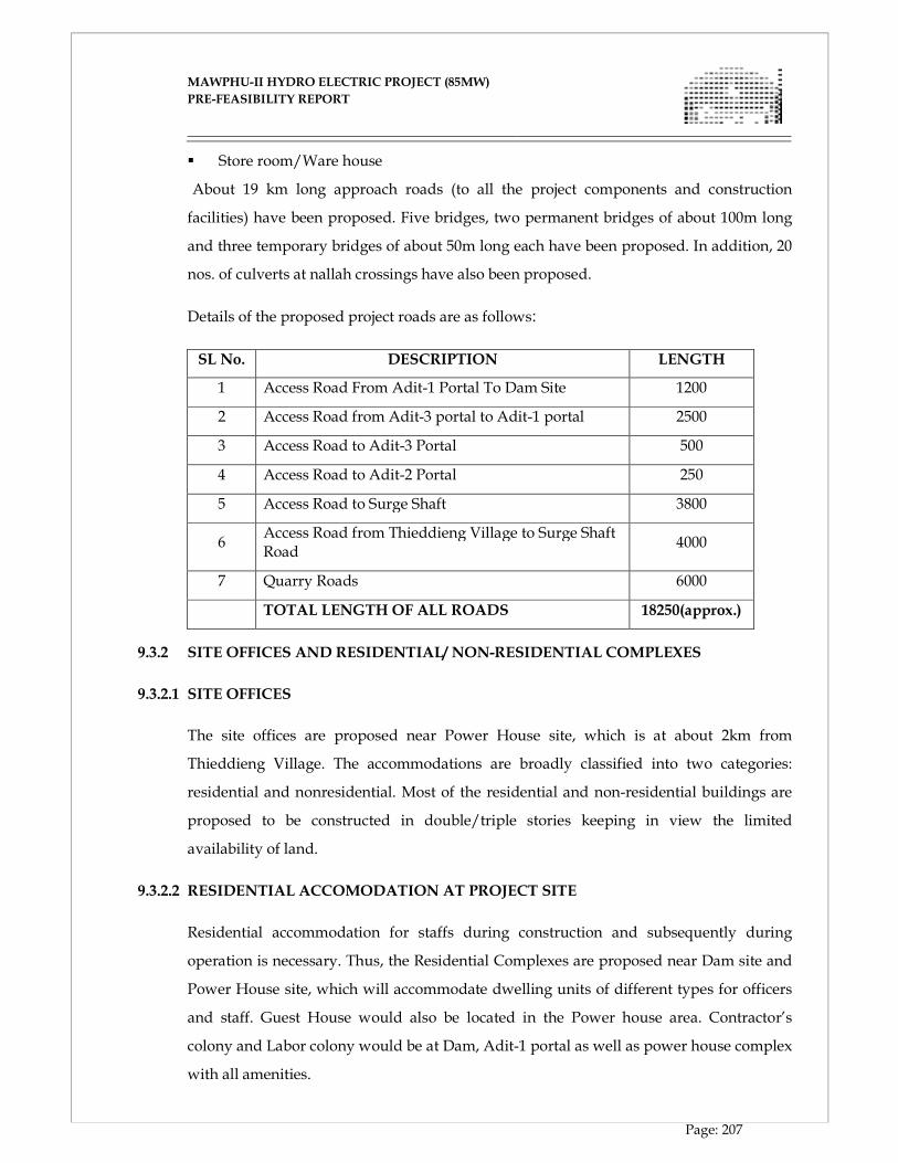
MAWPHU-II HYDRO ELECTRIC PROJECT (85MW)
MAWPHU-II HYDRO ELECTRIC PROJECT (85MW)
PRE-FEASIBILITY REPORT
Page: 207
� Store room/Ware house
About 19 km long approach roads (to all the project components and construction
facilities) have been proposed. Five bridges, two permanent bridges of about 100m long
and three temporary bridges of about 50m long each have been proposed. In addition, 20
nos. of culverts at nallah crossings have also been proposed.
Details of the proposed project roads are as follows:
SL No. DESCRIPTION LENGTH
1 Access Road From Adit-1 Portal To Dam Site 1200
2 Access Road from Adit-3 portal to Adit-1 portal 2500
3 Access Road to Adit-3 Portal 500
4 Access Road to Adit-2 Portal 250
5 Access Road to Surge Shaft 3800
6 Access Road from Thieddieng Village to Surge Shaft Road
4000
7 Quarry Roads 6000
TOTAL LENGTH OF ALL ROADS 18250(approx.)
9.3.2 SITE OFFICES AND RESIDENTIAL/ NON-RESIDENTIAL COMPLEXES
9.3.2.1 SITE OFFICES
The site offices are proposed near Power House site, which is at about 2km from
Thieddieng Village. The accommodations are broadly classified into two categories:
residential and nonresidential. Most of the residential and non-residential buildings are
proposed to be constructed in double/triple stories keeping in view the limited
availability of land.
9.3.2.2 RESIDENTIAL ACCOMODATION AT PROJECT SITE
Residential accommodation for staffs during construction and subsequently during
operation is necessary. Thus, the Residential Complexes are proposed near Dam site and
Power House site, which will accommodate dwelling units of different types for officers
and staff. Guest House would also be located in the Power house area. Contractor’s
colony and Labor colony would be at Dam, Adit-1 portal as well as power house complex
with all amenities.
MAWPHU-II HYDRO ELECTRIC PROJECT (85MW)
MAWPHU-II HYDRO ELECTRIC PROJECT (85MW)
PRE-FEASIBILITY REPORT
Page: 208
9.3.2.3 NON-RESIDENTIAL COMPLEXES AT PROJECT SITE
Non-residential complexes at Project Site will include Hospital/Dispensary, School,
Officers Club & Auditorium, Staff Club/ Union Office, Shopping Centre, Bank,
Telephone Exchange, Canteen, Stores, Sub-station, Fire Station, Filtration Plant, DG
Building, Quality Control Laboratory, CISF store/office, LPG Godown etc. and all these
structures will be needed during O & M stage as well. Most of the residential and non-
residential buildings are proposed to be constructed in double/triple stories at the project
site keeping in view the availability of land. The entire infrastructure will be utilized
during Operation & Maintenance (O&M) stage of the project also.
9.3.3 WORKSHOPS
Central workshop for heavy earth moving equipment and transport vehicles shall be set
up at the project site. The area shall be developed considering open space and parking
area. The workshop shall comprise of covered/semi-covered repair sheds. The workshop
shall comprise facilities for the engine repairs and overhauling, transmission, torque
converter repair shops, auto-electrical shops, machine shop, tyre repair shop, welding
and fabrication shops, chassis repairs, body and seat repairs, denting/painting,
maintenance yard etc.
9.3.4 WAREHOUSES/ STORES COMPLEX
Space for construction of stores for Cement, Steel and other materials including chemicals
will be identified in a relatively flatter area on the right bank of River. The steel and other
store items like bitumen etc. which do not require covered area would be kept outside in
open. For the purpose of cement storage, covered sheds shall be developed enabling
storage of adequate quantity of cement.
9.3.5 MUCK DISPOSAL AREA
The construction of various hydraulic structures like concrete dam, intake, power house
etc. will involve large excavation that would be disposed of in designated muck disposal
areas shown in the drawing no. 0933-CDC-01A-005-00, appended in Volume-IA of this
report. Muck arising from the cutting for roads would be utilized for filling wherever
required and the remaining would be disposed of in the nearby identified areas. The total
area identified for muck disposal for the whole project components is about 15.25 Ha.
MAWPHU-II HYDRO ELECTRIC PROJECT (85MW)
MAWPHU-II HYDRO ELECTRIC PROJECT (85MW)
PRE-FEASIBILITY REPORT
Page: 209
9.3.6 EXPLOSIVE MAGAZINE
In order to cater for blasting requirements of various work sites, it is planned to provide
one permanent explosive magazine along with proportionate quantity of detonators. Two
portable site magazines of 500 kg capacity will also be provided to cater for the day to
day requirement of explosives. All safety codes and regulations prescribed by the Govt.
in this respect will be followed and magazines will be suitably guarded round the clock.
Necessary approvals will be taken from the concerned authorities for these magazines.
Magazine areas have been proposed one on right bank at Dam site, one between Adit 1
and 2.
9.3.7 CONSTRUCTION PLANT FACILITIES
Various installations like crushing plant, batching and mixing plant etc. are to be put up
by the contractor near the working sites.
9.3.7.1 CRUSHING PLANT
Aggregate Crushing plant will be provided for aggregate preparation from excavated
material from surface and underground works. The details are given below:
� Crushing plant of 1 no.170 TPH and 1 no.110 TPH Capacity will be located at dam
site.
� Crushing Plant of 1 no. 170TPH and 1 no. 40 TPH will be placed near Power house
site.
9.3.7.2 BATCHING AND MIXING PLANT
As per requirement of concreting at various work sites, batching and mixing plants are
planned as under
� B & M plant of 2 nos. 60 cum/hr capacity at Dam site to meet the peak production of
concrete.
� B & M plant of 30 cum/hr capacity each near Power house site
PRESSURE SHAFT FERRULE FABRICATION YARD
Site for fabrication of pressure shaft ferrules will be provided by the erection contractor of
pressure shaft on the right bank, u/s of Power House complex.
MAWPHU-II HYDRO ELECTRIC PROJECT (85MW)
MAWPHU-II HYDRO ELECTRIC PROJECT (85MW)
PRE-FEASIBILITY REPORT
Page: 210
9.3.8 LAND REQUIREMENT
Land required for residential and non-residential buildings for the construction of the
approach roads, project components, workshops, stores, muck disposal, magazines,
construction plant facilities etc. will be acquired.
DETAILS OF LAND REQUIREMENT ARE AS FOLLOWS
Component Area(Ha)
Residential/Non Residential Area at Dam Site 1.5
Residential/Non Residential Area at PH Site 1.5
Total Area Required For Proposed Roads 17.70
Area proposed for Quarry area 6.5
Area Required for Power House 3.5
Area Required For Adit/Access Tunnels 2.25
Area Required at Surge Shaft Top 2.0
Area Required at Dam complex 9.0
Area required for HRT 6.2
Submergence area 13.0
Contractor facility/Labour Colony – Adit-1 1.0
Contractor facilities Area at Dam site 1.0
Fabrication Yard 1.5
Aggregate Crushing Plant near Dam site 1.0
Aggregate Crushing Plant near adit-1 1.0
Aggregate Crushing Plant near PH site 1.0
Area covering pressure shaft, road to power house, dumping, Area for SS, temporary colony for PH and adit-3 alignment (partly)
25.0
MAWPHU-II HYDRO ELECTRIC PROJECT (85MW)
MAWPHU-II HYDRO ELECTRIC PROJECT (85MW)
PRE-FEASIBILITY REPORT
Page: 211
Muck Dumping
Near Dam Complex 5.25
Near Adit-1 2.5
Adit-2 2.0
Adit-3 2.0
Power House (Right Bank) 2.0
Power House (Left Bank) 1.5
Magazine
Dam complex 0.1
Between Adit 1 & 2 0.1
Total 110.0
9.3.9 CONSTRUCTION POWER
Power will be required at various project locations during construction to power the
construction equipment. The area to be catered for construction power will consist of the
Dam site, HRT adits, Surge shaft and Pressure Shaft, Power House and the tail pool and
colony and office area. Diesel generating sets will be used to power these areas and
associated LT boards and cables will be provided to distribute power at various
equipment.
In addition to the loads of construction equipment, construction power will also cater to
the power demands of the dewatering system, ventilation system, illumination system
etc. It will be ensured that the diesel generating sets are located close to the load centers
at the dam site, Power House, colony and office and the diesel generating sets for HRT
adits, surge shaft and pressure shaft will located at their adit portals. The possibility of
tapping the local grid power will also be studied during the tendering stage, wherein the
capability of the local grid to supply construction power can be assessed based on the
loads and distribution system of nearby areas.

MAWPHU-II HYDRO ELECTRIC PROJECT (85MW)
MAWPHU-II HYDRO ELECTRIC PROJECT (85MW)
PRE-FEASIBILITY REPORT
Page: 212
9.3.10 TELECOMMUNICATION
The different work sites of the project offices, stores, laboratories, workshops and
residences etc. will be connected by a telecommunication network including telephones
for all offices and residences of senior officers etc. The telecommunication facilities will
also be provided between the project & various major cities of India.
9.3.11 WATER SUPPLY SYSTEM
Permanent residential area is planned at Power House area. A small one is also proposed
at Dam Site. In addition to this, labour camps are planned to be established at various
locations of activities. Arrangement of clean /portable water in the residential areas and
various construction sites are to be made for all these places.
9.3.12 SECURITY AND SAFETY ARRANGEMENT
9.3.12.1 SECURITY STAFF OFFICES AND CHECK POST
Two Nos. of Security staff Offices of suitable size each, one located at Dam site & the
other at Power House site are proposed to be provided. Along with these security staff
offices, check Posts are also to be provided. Sufficient Nos. of Security Personnel is
proposed to be provided including Day & Night shift duties. Those Security Personnel
will be looking after the entire project area.
9.3.12.2 FIRE STATION
Two Fire stations of suitable size each are proposed; one at dam site and other at power
house site. These Fire stations will be fully equipped with modern firefighting
equipment. Skilled Security Personnel will be used for firefighting Process.

CHAPTER - X
CONSTRUCTION PLANNING
MAWPHU-II HYDRO ELECTRIC PROJECT (85MW)
MAWPHU-II HYDRO ELECTRIC PROJECT (85MW)
PRE-FEASIBILITY REPORT
Page: 213
CHAPTER - X
CONSTRUCTION PROGRAM AND PROJECT SCHEDULE
10.1. PROJECT COMPONENTS
The project comprises construction of following components:
a) 384m long, 7m φ Horse Shoe Shape Diversion Tunnel
b) b. 51m high Concrete Gravity Dam along with other appurtenant structures
c) c. Km long, 4.80m φ Horse Shoe Shaped Head Race Tunnel, with 2 intermediate
Adits
i) Adit – 1: 6m D - Shaped at RD 862 78m long
ii) Adit – 2: 6m D - Shaped near surge shaft 124m Long
d) 10m dia, 54 m high Surge Shaft
e) Pressure Shaft
i) 3.5m φ 864m long, bifurcating into 2 limb of 2.5 m φ each 32m long
ii) Adit-2A to top horizontal Pressure Shaft, 6m dia D shaped 95m long
iii) Adit-2B to erection chamber, 6m dia, 121 m long
iv) Adit 3 to bottom horizontal pressure shaft, 6m dia D-shaped, 455 m long
f) Erection Chamber of Pressure shaft 8m x 8mx 8m
g) Surface Power House (66.0 m x 18.00 m x 30.50 m), housing 2 no Vertical Axis
Francis Turbine ( 2 x 42.50MW)
h) 51m long Tail Race Channel including recovery bay
10.2 CLIMATIC CONDITIONS
The proposed dam is near to the village Mawphu (L/B) and the power house is near to
Thieddieng village (R/B) in East Khasi Hills District of Meghalaya. The climate of the sub
basin is characterized by torrential rains caused by South West monsoon and 60% to 70%
rainfall occurs between June to September. The river flows in deep channel and swells
into torrents during the rainy season while during the remaining months it has not much
significant flow. The river has floods during June to October with peaks mostly occurring
in July to September.
MAWPHU-II HYDRO ELECTRIC PROJECT (85MW)
MAWPHU-II HYDRO ELECTRIC PROJECT (85MW)
PRE-FEASIBILITY REPORT
Page: 214
10.3 ASSUMPTIONS WHILE FRAMING THE SCHEDULE
� Non monsoon Season from November to May.
� Monsoon Season – June to October. Due to heavy rainfall in the region, construction
activities for surface works like Dam & Power house would be significantly
impacted during the monsoon season. The underground works would also be
impacted, though relatively less as compared to surface construction works.
However, as the construction agency would remain mobilized at site during the
monsoon season, the construction activity shall be continued with less progress. For
preparing the schedule, it is assumed that:
� Surface works - Production in wet season (Monsoon period) shall be 30% of
production achieved in dry season for surface works.
� Underground Works - Production in wet season (Monsoon period) shall be
50% of production achieved in dry season for underground works.
� Work shall be carried out in 3 shifts of 8 hrs each, with 80% job efficiency factor
i.e. 50 min / hr.
10.4 SCHEDULE OF WORK 10.4.1 RIVER DIVERSION WORKS
A) DT INLET WORKS
Quantity in open excavation = 8162 m3
Quantity in Concreting = 1600 m3
The works shall commence in the Non monsoon season. The open excavation in rock and
overburden will be carried out according to the principle of “excavating from top to
down and by layers and benches”. The drilling pattern shall be such that per blast 250 m3
of rock is blasted and there shall be two such cycles/day ( i.e. one blast in 12 Hrs) .
Concreting in the DT inlet shall be taken up along with the lining works in the Diversion
tunnel after excavation of DT is completed. The procedure for concreting would be:
Foundation clearance -- surveying and setting out -- formwork erection --
reinforcement and water stop installation -- inspection- transportation of concrete --
concrete pouring -- formwork removal -- curing. The lift height would be around 1.5m.
The average cycle time for pouring concrete in one lift of height 1.5 meter shall be 2 days
and average quantity of concrete per poured shall be 110 cum.
MAWPHU-II HYDRO ELECTRIC PROJECT (85MW)
MAWPHU-II HYDRO ELECTRIC PROJECT (85MW)
PRE-FEASIBILITY REPORT
Page: 215
B) DIVERSION TUNNEL
Excavation will be carried out from Inlet and outlet end simultaneously. Full face
excavation will be implemented using drilling and blasting method. Average cycle time
for excavation in class 1,2 and 3 is worked out as 16.2 hrs and average cycle for
excavation in class 4 & 5 rock has been worked out as 19 hrs.
Total length of Tunnel : 384m
Length of Tunnel in Class 1, 2 and 3 : 308m
Length of Tunnel in Class 4 & 5 : 76m
Pull Planned / Blast : 03 m
Class of Rock Average rate of Progress
Total no of days
required to complete
Average rate of progress/day / face in Class 1,2,3 4.4m/day 70 days
Average rate of progress/day / face in Class 4 & 5 3.8m/day 20days
Total no of days for excavating DT from one face 90
Average rate of progress/day / for 4,2m / day
It is planned to carry out the lining in diversion tunnel using a 12 m long gantry. The
shutter shall move from Inlet toward the outlet, and concrete shall be feed from outlet
end of the tunnel. This arrangement will facilitate in carrying out concreting & HM work
at Inlet, simultaneously with the tunnel concreting. The average cycle time for concrete
lining shall be 26.7 hrs. And average rate of progress per day shall be 10.78 m/ day.
C) RIVER DIVERSION & CONSTRUCTION OF COFFER DAM
It is planned to divert the river in 6th month after the start of construction during lean
season flow. The river diversion shall be achieved by constructing a closure dyke. There
after the construction of Cofferdam shall be undertaken. U/s Cofferdam is proposed to
be founded on overburden. The maximum height of the coffer dam is 18m from the river
bed level. . The central core of the coffer dam is filled with clay. Materials from
excavation of Diversion Tunnel, DT inlet and outlet will be used for coffer dams. . Filling
of the cofferdam will be carried out in layers of no more than 100cm each. Compaction
roller will be used to compact in layers. Total quantity of rock fill in the coffer dam is
equal to 71,690 cum and targeted average rate of placing rock fill shall be 4320 cum.
MAWPHU-II HYDRO ELECTRIC PROJECT (85MW)
MAWPHU-II HYDRO ELECTRIC PROJECT (85MW)
PRE-FEASIBILITY REPORT
Page: 216
10.4.2 DAM AND SPILLWAYS
Total excavation involved in dam
� Excavation in Overburden/Soil = 58,300 cum
� Excavation in Rock = 93.300 cum
Total = 1,51,600 cum
Further Break up of Excavation Qty :
i) In Abutment - From top to HFL = 34,000 cum
ii) Abutments – from HFL to River bed level = 15,000 cum
iii) From river bed level to deepest foundation level = 1,03,000 cum
Abutment above HFL involving quantity of 34,000 cum shall be taken up prior to river
diversion works. The excavation of abutments below the HFL shall be taken up after the
river diversion is achieved. Excavation in river bed shall also be taken up after the river
diversion has been achieved. The excavation in riverbed shall be undertaken only in non-
monsoon season. The works have been planned accordingly. The open excavation will be
carried out according to the principle of “excavating from top to down and by layers and
benches. The drilling pattern shall be such that per blast 500 m3 of rock is blasted and
there shall be two such cycles/day (i.e. one blast in 12 Hrs).
CONCRETING IN DAM
The procedure for concreting in dam is as following: Foundation clearance -- surveying
and setting out -- formwork erection -- reinforcement and water-stop installation –
inspection -- concrete pouring -- formwork removal -- curing.
Total quantity of concrete to be placed in dam =
From Deepest foundation level to river bed = 52,125 cum
From river bed level to Dam top = 86,875 cum
Total =1,39,000 cum
Peak placement of concrete in the dam would be when the concrete in poured in the
overflow blocks 3,4 and 5 below the river bed level. Following is planned for pouring the
concrete :
� Concrete shall be placed in lift heights of 1.5m. In each lift concrete shall be poured
in layers of 0.5m height.
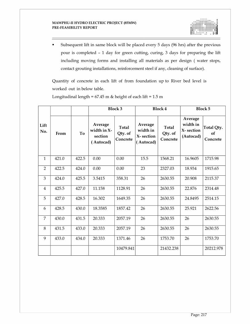
MAWPHU-II HYDRO ELECTRIC PROJECT (85MW)
MAWPHU-II HYDRO ELECTRIC PROJECT (85MW)
PRE-FEASIBILITY REPORT
Page: 217
� Subsequent lift in same block will be placed every 5 days (96 hrs) after the previous
pour is completed – 1 day for green cutting, curing, 3 days for preparing the lift
including moving forms and installing all materials as per design ( water stops,
contact grouting installations, reinforcement steel if any, cleaning of surface).
Quantity of concrete in each lift of from foundation up to River bed level is
worked out in below table.
Longitudinal length = 67.45 m & height of each lift = 1.5 m
Lift
No.
Block 3 Block 4 Block 5
From
To
Average
width in X-
section
( Autocad)
Total
Qty. of
Concrete
Average
width in
X- section
( Autocad)
Total
Qty. of
Concrete
Average
width in
X- section
(Autocad)
Total Qty.
of
Concrete
1 421.0 422.5 0.00 0.00 15.5 1568.21 16.9605 1715.98
2 422.5 424.0 0.00 0.00 23 2327.03 18.934 1915.65
3 424.0 425.5 3.5415 358.31 26 2630.55 20.908 2115.37
4 425.5 427.0 11.158 1128.91 26 2630.55 22.876 2314.48
5 427.0 428.5 16.302 1649.35 26 2630.55 24.8495 2514.15
6 428.5 430.0 18.3585 1857.42 26 2630.55 25.921 2622.56
7 430.0 431.5 20.333 2057.19 26 2630.55 26 2630.55
8 431.5 433.0 20.333 2057.19 26 2630.55 26 2630.55
9 433.0 434.0 20.333 1371.46 26 1753.70 26 1753.70
10479.841 21432.238 20212.978
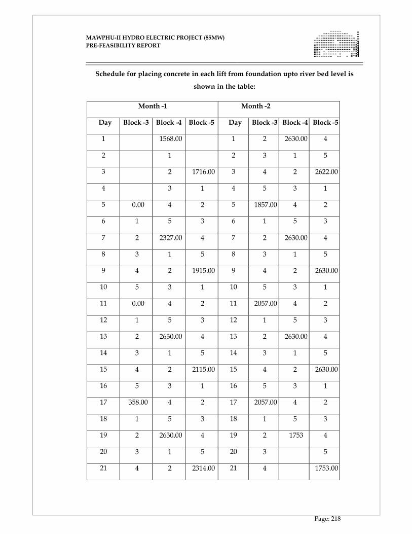
MAWPHU-II HYDRO ELECTRIC PROJECT (85MW)
MAWPHU-II HYDRO ELECTRIC PROJECT (85MW)
PRE-FEASIBILITY REPORT
Page: 218
Schedule for placing concrete in each lift from foundation upto river bed level is
shown in the table:
Month -1 Month -2
Day Block -3 Block -4 Block -5 Day Block -3 Block -4 Block -5
1 1568.00 1 2 2630.00 4
2 1 2 3 1 5
3 2 1716.00 3 4 2 2622.00
4 3 1 4 5 3 1
5 0.00 4 2 5 1857.00 4 2
6 1 5 3 6 1 5 3
7 2 2327.00 4 7 2 2630.00 4
8 3 1 5 8 3 1 5
9 4 2 1915.00 9 4 2 2630.00
10 5 3 1 10 5 3 1
11 0.00 4 2 11 2057.00 4 2
12 1 5 3 12 1 5 3
13 2 2630.00 4 13 2 2630.00 4
14 3 1 5 14 3 1 5
15 4 2 2115.00 15 4 2 2630.00
16 5 3 1 16 5 3 1
17 358.00 4 2 17 2057.00 4 2
18 1 5 3 18 1 5 3
19 2 2630.00 4 19 2 1753 4
20 3 1 5 20 3 5
21 4 2 2314.00 21 4 1753.00
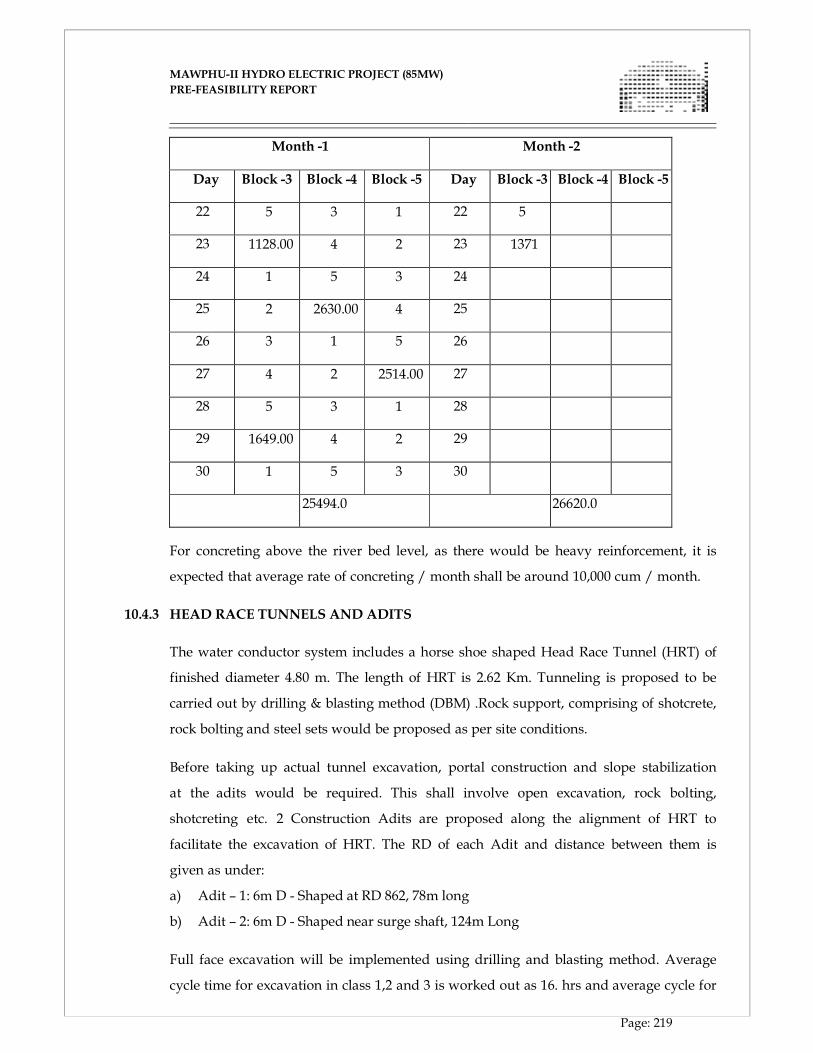
MAWPHU-II HYDRO ELECTRIC PROJECT (85MW)
MAWPHU-II HYDRO ELECTRIC PROJECT (85MW)
PRE-FEASIBILITY REPORT
Page: 219
Month -1 Month -2
Day Block -3 Block -4 Block -5 Day Block -3 Block -4 Block -5
22 5 3 1 22 5
23 1128.00 4 2 23 1371
24 1 5 3 24
25 2 2630.00 4 25
26 3 1 5 26
27 4 2 2514.00 27
28 5 3 1 28
29 1649.00 4 2 29
30 1 5 3 30
25494.0 26620.0
For concreting above the river bed level, as there would be heavy reinforcement, it is
expected that average rate of concreting / month shall be around 10,000 cum / month.
10.4.3 HEAD RACE TUNNELS AND ADITS
The water conductor system includes a horse shoe shaped Head Race Tunnel (HRT) of
finished diameter 4.80 m. The length of HRT is 2.62 Km. Tunneling is proposed to be
carried out by drilling & blasting method (DBM) .Rock support, comprising of shotcrete,
rock bolting and steel sets would be proposed as per site conditions.
Before taking up actual tunnel excavation, portal construction and slope stabilization
at the adits would be required. This shall involve open excavation, rock bolting,
shotcreting etc. 2 Construction Adits are proposed along the alignment of HRT to
facilitate the excavation of HRT. The RD of each Adit and distance between them is
given as under:
a) Adit – 1: 6m D - Shaped at RD 862, 78m long
b) Adit – 2: 6m D - Shaped near surge shaft, 124m Long
Full face excavation will be implemented using drilling and blasting method. Average
cycle time for excavation in class 1,2 and 3 is worked out as 16. hrs and average cycle for
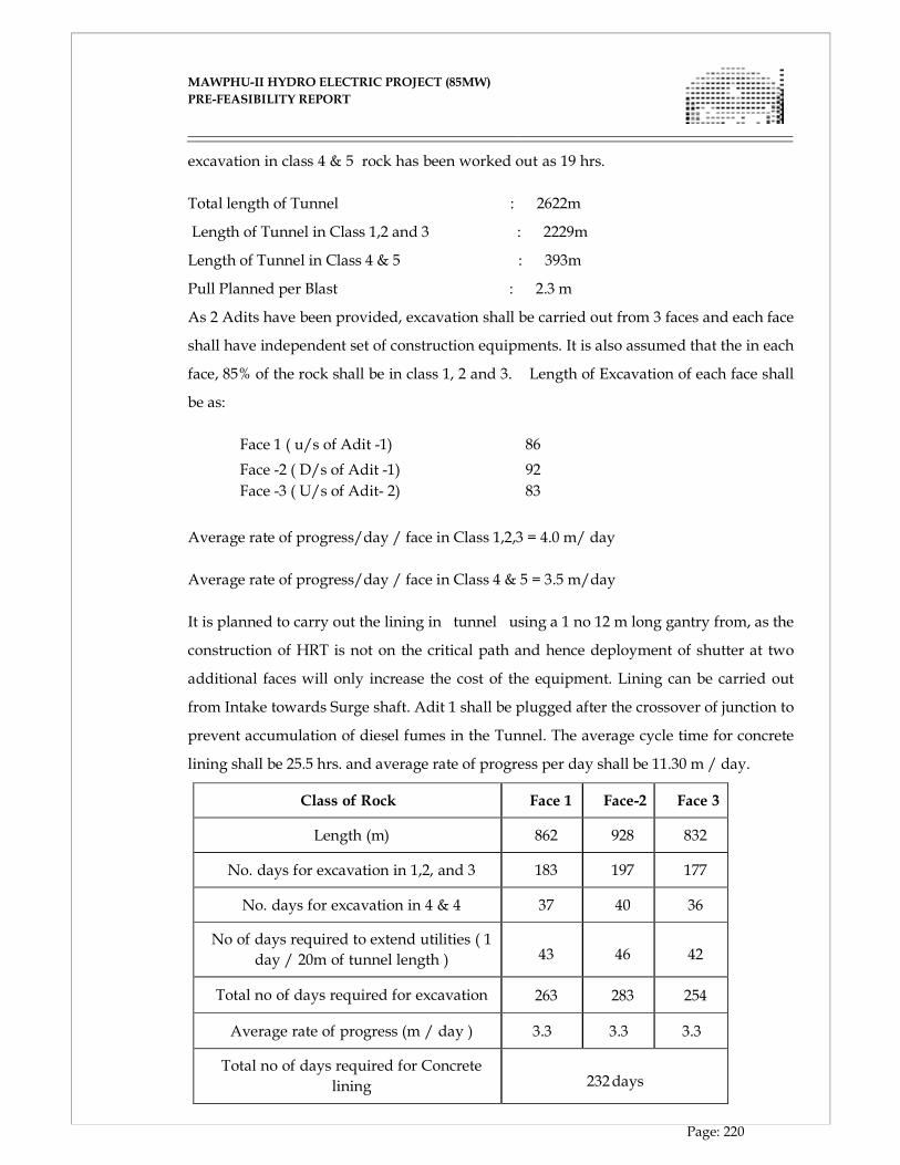
MAWPHU-II HYDRO ELECTRIC PROJECT (85MW)
MAWPHU-II HYDRO ELECTRIC PROJECT (85MW)
PRE-FEASIBILITY REPORT
Page: 220
excavation in class 4 & 5 rock has been worked out as 19 hrs.
Total length of Tunnel : 2622m
Length of Tunnel in Class 1,2 and 3 : 2229m
Length of Tunnel in Class 4 & 5 : 393m
Pull Planned per Blast : 2.3 m
As 2 Adits have been provided, excavation shall be carried out from 3 faces and each face
shall have independent set of construction equipments. It is also assumed that the in each
face, 85% of the rock shall be in class 1, 2 and 3. Length of Excavation of each face shall
be as:
Face 1 ( u/s of Adit -1) 86
Face -2 ( D/s of Adit -1) 92
Face -3 ( U/s of Adit- 2) 83
Average rate of progress/day / face in Class 1,2,3 = 4.0 m/ day
Average rate of progress/day / face in Class 4 & 5 = 3.5 m/day
It is planned to carry out the lining in tunnel using a 1 no 12 m long gantry from, as the
construction of HRT is not on the critical path and hence deployment of shutter at two
additional faces will only increase the cost of the equipment. Lining can be carried out
from Intake towards Surge shaft. Adit 1 shall be plugged after the crossover of junction to
prevent accumulation of diesel fumes in the Tunnel. The average cycle time for concrete
lining shall be 25.5 hrs. and average rate of progress per day shall be 11.30 m / day.
Class of Rock Face 1 Face-2 Face 3
Length (m) 862 928 832
No. days for excavation in 1,2, and 3 183 197 177
No. days for excavation in 4 & 4 37 40 36
No of days required to extend utilities ( 1
day / 20m of tunnel length )
43
46
42
Total no of days required for excavation 263 283 254
Average rate of progress (m / day ) 3.3 3.3 3.3
Total no of days required for Concrete
lining
232 days
MAWPHU-II HYDRO ELECTRIC PROJECT (85MW)
MAWPHU-II HYDRO ELECTRIC PROJECT (85MW)
PRE-FEASIBILITY REPORT
Page: 221
10.4.4 POWER HOUSE
Quantity in open excavation = 5, 05,000 m3
Quantity in Concreting
� Sub structure = 3000 m3
� Superstructure = 6000 m3
The excavation works shall commence immediately after completing the mobilization.
The open excavation in rock and overburden will be carried out according to the
principle of “excavating from top to down and by layers and benches”. The drilling
pattern shall be such that per blast 500 m3 of rock is blasted and there shall be two such
cycles/day (i.e. one blast in 12 Hrs).
After completing the excavation & sub structure concreting, the erection of turbines &
generators shall be taken up, which will take about 12 months for each machine?
Superstructure Concreting shall continue with the erection of E&M equipment as and
when required.

CHAPTER - XI
ENVIRONMENT AND ECOLOGY
MAWPHU-II HYDRO ELECTRIC PROJECT (85MW)
MAWPHU-II HYDRO ELECTRIC PROJECT (85MW)
PRE-FEASIBILITY REPORT
Page: 222
CHAPTER - XI
ENVIRONMENT AND ECOLOGY
11.1 INTRODUCTION
The environmental Examination of the proposed Mawhu H. E. Project has following
objectives which are proposed to be covered during various phases of development.
� Provide information on baseline environmental setting.
� Assessment of impacts likely to accrue during construction and operation phases;
� Identify key issues which need to be studied in detail during environmental studies
It is essential to ascertain the baseline status of relevant environmental parameters that
could undergo significant changes as a result of construction and operation of the project.
Baseline status has been ascertained through review of secondary data, reconnaissance
survey and interaction with the locals.
The environmental study has been conducted as a part of EIA study to forecast the future
environmental scenario of the project area that might be expected to occur as a result of
construction and operation of the proposed project. The key environmental impacts
which are likely to accrue as a result of the proposed developmental activity are
identified. Various impacts, which can endanger the environmental sustainability of a
project, are highlighted for comprehensive assessment as a part of next level of
environmental study.
11.2 ENVIRONMENTAL BASELINE SETTING
The study area includes the area within 7 km radius of various project appurtenances.
The data was collected through review of existing documents and various engineering
reports and reconnaissance surveys. The various parameters for which baseline setting
has been described have been classified into physio-chemical, ecological and socio-
ecological aspects.
11.2.1 PHYSIO-CHEMICAL ASPECTS
a) WATER QUALITY
The proposed hydroelectric project is located on Umiew river. The catchment area
intercepted at the project site has a low population density. The low cropping intensity
MAWPHU-II HYDRO ELECTRIC PROJECT (85MW)
MAWPHU-II HYDRO ELECTRIC PROJECT (85MW)
PRE-FEASIBILITY REPORT
Page: 223
coupled with low agro-chemicals dosing ensures that the pollution loading due to agro-
chemicals is quite low. The absence of industries implies that there is no pollution
loading from this source as well. Thus, it can be concluded that there are no major
sources of pollution in the project area.
It has been observed that, water quality in such settings is quite good, characterized by
high DO and low BOD levels. The TDS levels too are low, i.e. well within the permissible
limits, which could be used for drinking purposes. The major sources of water are
various streams and nallahs flowing adjacent to various settlements. The water is
transported to the point of consumption under gravity. The sewage so generated too is
disposed without any treatment in natural streams and channels. Due to low population
density and presence of sufficient water for dilution, no adverse impact on water quality
is observed. Thus, water of Umiew river can be classified as class-A as per IS 2296, which
means that water can be used for meeting domestic requirements after disinfection, and
without conventional treatment. It is pertinent to mention that the Greater Shillong Water
Supply Scheme is located about 10 Km upstream of the proposed Dam site on the same
river.
b) LANDUSE
The submergence area is 13.0 ha at FRL, which comprises mainly of mixed forest and
water bodies. Additional land will be required for siting of various project appurtenances
as well.
11.2.2 ECOLOGICAL ASPECTS
a) VEGETATION
The proposed project site lies in the eastern Himalayas. The nature and type of vegetation
occurring in an area depends upon a combination of various factors including prevailing
climatic conditions altitude, topography, slope, biotic factors, etc.
As per the altitude the major vegetation type observed in the project area and the study
area is mixed forests. The characteristic feature of these forests is that top canopy is
predominated by deciduous species whose leafless period is short. In quality the forests
contain much poorer type of timber than the evergreen forests and are composed of a
number of species that are of little commercial value.
The major floral species observed in the study area are given in Table 11.1.
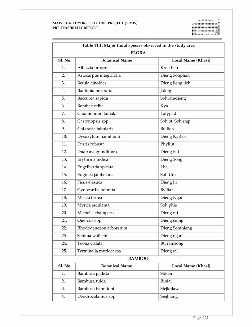
MAWPHU-II HYDRO ELECTRIC PROJECT (85MW)
MAWPHU-II HYDRO ELECTRIC PROJECT (85MW)
PRE-FEASIBILITY REPORT
Page: 224
Table 11.1: Major floral species observed in the study area
FLORA
Sl. No. Botanical Name Local Name (Khasi)
1. Albizzia procera Kreit lieh
2. Artocarpus integrifolia Dieng Sohphan
3. Betula alnoides Dieng lieng lieh
4. Bauhinia purpuria Jalong
5. Baccurea sapida Sohramdieng
6. Bombax ceiba Kya
7. Cinamomum tamala Latypad
8. Castonopsis spp Soh ot, Soh stap
9. Chikrasia tabularis Bti lieh
10. Dysoxylum hamiltonii Dieng Kyrbei
11. Derris robusta Phyllut
12. Duabana grandiflora Dieng Bai
13. Erythrina indica Dieng Song
14. Engelhertia spicata Lba.
15. Euginea jambolana Soh Um
16. Ficus elastica Dieng Jri
17. Gynocardia odorata Bylliat
18. Mesua ferrea Dieng Ngai
19. Myrica esculanta Soh phie
20. Michelia champaca Dieng rai
21. Quercus spp Dieng sning
22. Rhododendron arboretum Dieng Sohthiang
23. Schima wallichii Dieng ngan
24. Toona cialata Bti ramsong
25. Terminalia myriocarpa Dieng tal
BAMBOO
Sl. No. Botanical Name Local Name (Khasi)
1. Bambusa pallida Shken
2. Bambusa tulda Riniai
3. Bambusa hamiltoni Siejkhlaw
4. Dendrocalamus spp Siejktang
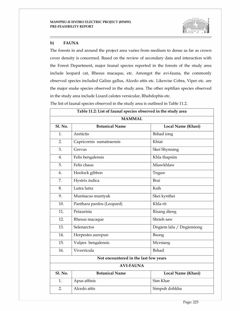
MAWPHU-II HYDRO ELECTRIC PROJECT (85MW)
MAWPHU-II HYDRO ELECTRIC PROJECT (85MW)
PRE-FEASIBILITY REPORT
Page: 225
b) FAUNA
The forests in and around the project area varies from medium to dense as far as crown
cover density is concerned. Based on the review of secondary data and interaction with
the Forest Department, major faunal species reported in the forests of the study area
include leopard cat, Rhesus macaque, etc. Amongst the avi-fauna, the commonly
observed species included Galius gallus, Alcedo attis etc. Likewise Cobra, Viper etc. are
the major snake species observed in the study area. The other reptilian species observed
in the study area include Lizard calotes versicular, Rhabdophis etc.
The list of faunal species observed in the study area is outlined in Table 11.2.
Table 11.2: List of faunal species observed in the study area
MAMMAL
Sl. No. Botanical Name Local Name (Khasi)
1. Aretictis Bshad iong
2. Capricornis sumatraensis Khiat
3. Cervus Skei Shynrang
4. Felis bengalensis Khla thapsim
5. Felis chaus Miawkhlaw
6. Hoolock gibbon Tngaw
7. Hystrix indica Brai
8. Lutra lutra Ksih
9. Muntiacus muntyak Skei kynthei
10. Panthara pardos (Leopard) Khla rit
11. Petaurista Risang dieng
12. Rhesus macaque Shrieh saw
13. Selenarctos Dngiem lalu / Dngiemiong
14. Herpestes auropun Bsong
15. Vulpes bengalensis Myrsiang
16. Viverricula Bshad
Not encountered in the last few years
AVI-FAUNA
Sl. No. Botanical Name Local Name (Khasi)
1. Apus affinis Sim Khar
2. Alcedo attis Simpuh dohkha
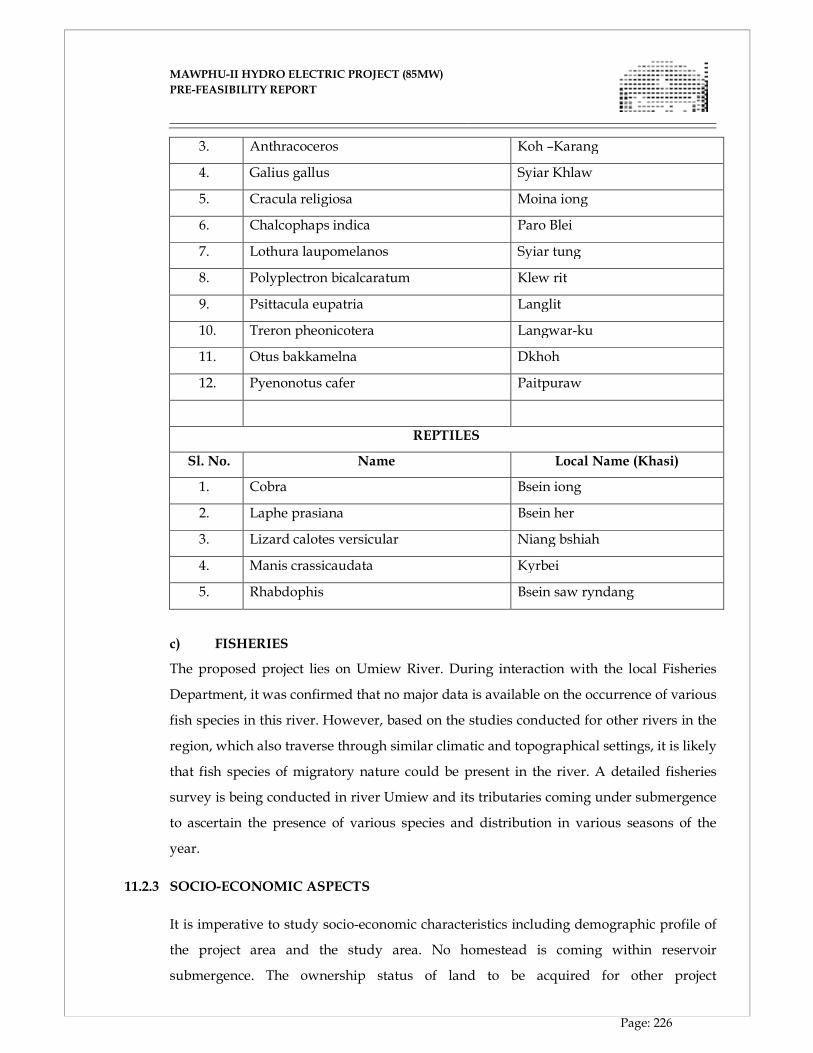
MAWPHU-II HYDRO ELECTRIC PROJECT (85MW)
MAWPHU-II HYDRO ELECTRIC PROJECT (85MW)
PRE-FEASIBILITY REPORT
Page: 226
3. Anthracoceros Koh –Karang
4. Galius gallus Syiar Khlaw
5. Cracula religiosa Moina iong
6. Chalcophaps indica Paro Blei
7. Lothura laupomelanos Syiar tung
8. Polyplectron bicalcaratum Klew rit
9. Psittacula eupatria Langlit
10. Treron pheonicotera Langwar-ku
11. Otus bakkamelna Dkhoh
12. Pyenonotus cafer Paitpuraw
REPTILES
Sl. No. Name Local Name (Khasi)
1. Cobra Bsein iong
2. Laphe prasiana Bsein her
3. Lizard calotes versicular Niang bshiah
4. Manis crassicaudata Kyrbei
5. Rhabdophis Bsein saw ryndang
c) FISHERIES
The proposed project lies on Umiew River. During interaction with the local Fisheries
Department, it was confirmed that no major data is available on the occurrence of various
fish species in this river. However, based on the studies conducted for other rivers in the
region, which also traverse through similar climatic and topographical settings, it is likely
that fish species of migratory nature could be present in the river. A detailed fisheries
survey is being conducted in river Umiew and its tributaries coming under submergence
to ascertain the presence of various species and distribution in various seasons of the
year.
11.2.3 SOCIO-ECONOMIC ASPECTS
It is imperative to study socio-economic characteristics including demographic profile of
the project area and the study area. No homestead is coming within reservoir
submergence. The ownership status of land to be acquired for other project
MAWPHU-II HYDRO ELECTRIC PROJECT (85MW)
MAWPHU-II HYDRO ELECTRIC PROJECT (85MW)
PRE-FEASIBILITY REPORT
Page: 227
appurtenances is being ascertained. The ST population is the dominant caste group. The
SC population is virtually negligible in the project area. The literacy rate in the study area
is quite high, i.e. of the order of 60%. The male and female literacy rates are more or less
equal, which is a typical feature of many areas in the north-eastern part of the country.
The ST population in and around the project area is a matrilineal society and both male as
well as female population actively take part in various socio-economic activities.
11.3 PREDICTION OF IMPACTS
Based on the project details and the baseline environmental status, potential impacts as a
result of the construction and operation of the proposed project have been identified.
Impacts on various aspects listed as below have been assessed:
� Land environment
� Water resources
� Water quality
� Terrestrial flora
� Terrestrial fauna
� Aquatic ecology
� Noise environment
� Ambient air quality
� Socio-economic environment
11.4 IMPACTS ON LAND ENVIRONMENT
a) CONSTRUCTION PHASE
Sufficient quantity of coarse and fine aggregate is required for construction of a
hydroelectric project. The fine aggregates are generally available as river shoal deposits.
During excavation in the river shoals, clay particles are likely to get entrained, which can
increase the turbidity of the water body. This may marginally affect the primary
productivity of the river. However, this scenario is likely to last only during the time for
which material is being excavated. The water quality is likely to return to its original
turbidity levels, few days after the cessation of excavation operations. The depressions so
created after excavation of the construction material is likely to be filled up by the
sediments/silts brought down by the river from which the material is being excavated.
MAWPHU-II HYDRO ELECTRIC PROJECT (85MW)
MAWPHU-II HYDRO ELECTRIC PROJECT (85MW)
PRE-FEASIBILITY REPORT
Page: 228
Thus, no specific management measures are required for extraction of construction
materials from shoal deposits.
The coarse aggregates will be extracted from various quarry sites in and around the
project area. The quarries have been located over non-forest land so as to minimize
adverse impacts on flora and fauna to the extent possible. The quarry sites are located
away from human settlements so as to avoid adverse impacts on them. Quarrying will be
done along the hill face, using semi-mechanized methods. Rock quality of the identified
quarries have been found to be very good. Proper care will be taken to provide required
slope during quarrying operation so that the quarrying faces remain stable. Since the
quality of rock encountered in the quarries is very good, weathering effect on the
quarried faces will not be significant and as such no additional treatment will be
required.
OPERATION OF CONSTRUCTION EQUIPMENT
During construction phase, various types of equipment will be brought to the site. These
include crushers, batching plant drillers, earthmover, rock bolters, etc. The sitting of
construction equipment would require significant amount of space. Similarly, space will
be required for storing various construction materials as well. The storage site will be
selected which is away from human habitations and faunal population.
There are no major habitation sites near the dam site and other project appurtenances.
Thus, sitting of construction equipment and storage of construction material are not
likely to have any adverse impacts.
SOIL EROSION
The runoff from the construction sites will have a natural tendency to flow towards
Umiew River or its tributaries. For some distance downstream of major construction
sites, such as dam, power house, etc. there is a possibility of increased sediment levels
which will lead to reduction in light penetration, which in turn could reduce the
photosynthetic activity to some extent of the aquatic plants as it depends directly on
sunlight. This change is likely to have an adverse impact on the primary biological
productivity of the affected stretch of the water body. Based on experience in other
projects, impacts on this account are not expected to be significant.
MAWPHU-II HYDRO ELECTRIC PROJECT (85MW)
MAWPHU-II HYDRO ELECTRIC PROJECT (85MW)
PRE-FEASIBILITY REPORT
Page: 229
PROBLEMS OF MUCK DISPOSAL
A large quantity of muck is expected to be generated as a result of tunneling operations,
excavation for Dam, construction of roads, etc. Normally, muck disposal sites are cleared
of vegetation before disposing the material. Trees are cut before muck disposal, however,
shrubs, grass or other types of undergrowth on which muck is disposed perishes.
In many projects, it has been observed that the muck generated by various sources is
disposed along the river valleys. The boulders are stacked along the river bank, and
during the next monsoons, the boulders can flow along with runoff, and ultimately find
their way into the river and finally into the plains. Hence, in this project adequate
measures wherever required, such as retaining walls, etc. will be constructed to
ameliorate the likely adverse impacts.
Construction of roads
The project construction would entail significant vehicular movement for transportation
of large construction material and heavy construction equipment. Most of the roads in
the project area would require widening. New roads would have to be constructed. The
construction of roads can lead to the following impacts:
� Removal of trees on slopes and re-working of the slopes in the immediate vicinity of
roads can encourage landslides, erosion gullies, etc. with the removal of vegetal
cover, erosive action of water gets pronounced and accelerates the process of soil
erosion and formation of deep gullies. Consequently, the hill faces are bared of soil
and vegetal cover and enormous quantities of soil and rock can move down the
rivers, and in some cases, the road itself may get washed out.
� Construction of new roads increases the accessibility of a hitherto undisturbed area
resulting in greater human interference and subsequent adverse impacts on the
ecosystem.
About 7 Km of the existing roads would require widening which are mostly passing over
plateau, as such, quantity involved in excavation & filling will be comparatively less. The
project would also require construction of new roads of about 19 Km length. Adequate
measures like stabilization of slopes, drainage, retaining wall, plantation of trees, grass
cover etc. will be taken for mitigating adverse impact of widening as well as construction
of new roads.

MAWPHU-II HYDRO ELECTRIC PROJECT (85MW)
MAWPHU-II HYDRO ELECTRIC PROJECT (85MW)
PRE-FEASIBILITY REPORT
Page: 230
b) OPERATION PHASE
The area coming under reservoir submergence is only 13.0 ha, comprising mainly of
mixed forest and water bodies. Additional area will be required for sitting of project
appurtenances, infrastructure, etc. The ownership category of such land needs to be
ascertained, once project layout is finalized as a part of DPR preparation. Based on the
type of land being acquired appropriate management measures shall be formulated.
Project appurtenances such as colonies, labour camps and other appurtenances, which
are not site-specific, will be located suitably so as to involve minimum cutting of trees etc.
11.5 IMPACTS ON WATER RESOURCES
The construction of dam as a part of the proposed project, diversion of discharge for
hydropower generation would lead to reduction in flow for a river stretch, downstream
of the dam site up to the confluence point of tail race discharge. Since there are no users
in the intervening stretch, hence, reduction in flow during lean season is unlikely to lead
to any significant impact. However, reduction in flow from the dam site up to the
confluence of these rivers is likely to have a minor impact on riverine ecology as the
discharge during lean flow is significantly less. Requirement for release of minimum
flow for sustenance of riverine fisheries is being assessed.
11.6 IMPACTS ON WATER QUALITY
a) CONSTRUCTION PHASE
EFFLUENT FROM LABOUR CAMPS
The project construction is likely to last for a period of 4-5 years apart from investigation
stage. About 1000 workers and 250 technical staff are likely to work during project
construction phase. The construction phase also leads to mushrooming of various allied
activities to meet the demands of the immigrant labour population in the project area.
Thus, the total increase in labour population during construction phase is expected to be
around 2500-3000. The total quantum of swage generated is expected to be of the order of
0.2 mld. The BOD load contributed by domestic sources will be about 135 kg/day. Since
disposal of untreated sewage could have adverse impacts on river water quality,
especially during lean season flow, care shall be taken not to dispose any untreated
sewage into Umiew river. It is a common practice during construction phase to
commission low cost sanitation treatment units and such units are required only during
the project construction phase. The sewage generated from the Labour Camps shall be
MAWPHU-II HYDRO ELECTRIC PROJECT (85MW)
MAWPHU-II HYDRO ELECTRIC PROJECT (85MW)
PRE-FEASIBILITY REPORT
Page: 231
treated through septic tanks.
EFFLUENT FROM CRUSHERS
The effluent from the crusher would contain high suspended solids. The effluent, if
disposed without treatment can lead led to marginal increase in the turbidity levels in the
receiving water bodies. However, no major adverse impacts are anticipated due to small
quantity of effluent and availability of sufficient water for dilution. The severity of
impacts would vary from season to season with variations in water availability for
dilution. A settling tank is proposed for arresting heavier solids from the effluent before
the effluent is disposed off.
b) OPERATION PHASE
EFFLUENT FROM PROJECT COLONY
In the operation phase, about 100 families will be residing in the area which would
generate about 0.08 mld of sewage. The quantum of sewage generated is not expected to
cause any significant adverse impact on riverine water quality. Adequate number of
septic tanks would be constructed for treatment of sewage to ameliorate the marginal
impacts.
IMPACTS ON RESERVOIR WATER QUALITY
The flooding of land with vegetation cover in the submergence area increases the
availability of nutrients resulting from decomposition of vegetative matter. Enrichment of
impounded water with organic and inorganic nutrients at times become a major water
quality problem immediately on commencement of the operation and is likely to
continue in the initial years of operation. In due course, the reservoir would support and
enhance the aquatic life including development of fisheries.
EUTROPHICATION RISKS
The fertilizer use in the project area is nil, hence, runoff at present does not contain
significant amount of nutrients. During post-project phase too, use of fertilizers in the
project catchment area is not expected to rise significantly. Eutrophication problems,
which are primarily caused by enrichment of nutrients in water are not anticipated in the
proposed project.
11.7 IMPACT ON TERRESTRIAL FLORA
a) CONSTRUCTION PHASE
MAWPHU-II HYDRO ELECTRIC PROJECT (85MW)
MAWPHU-II HYDRO ELECTRIC PROJECT (85MW)
PRE-FEASIBILITY REPORT
Page: 232
INCREASED HUMAN INTERFERENCES
As mentioned earlier, about 1250 technical staff, workers and other group of people are
likely to congregate in the area during the project construction phase. The total increase
in population is expected to be about 2500-3000. Workers and other population groups
residing in the area may use fuel wood, if no alternate fuel is provided. On an average,
the fuel wood requirements will be of the order of 1250-1350 m3 annually. Thus, every
year, fuel wood equivalent to about 400-450 trees will be cut, which implies that every
year on an average about 0.5 ha of dense forest area will be cleared for meeting fuel
wood requirements, if no alternate sources of fuel are provided. Dense forests are not
observed in the project and its surroundings. However, within the study area, some
pockets of dense forest are observed, which would be under threat if alternate fuel
sources are not provided to workers involved in project construction. The contractor
involved in construction activities will be asked to provide alternate source of fuel to the
labour population and their families involved in construction activities. Alternatively,
community kitchens using Kerosene or LPG as fuel can be run for the benefit of labour
population and their families.
b) OPERATION PHASE
The area coming under reservoir submergence comprises of mixed forest.
Compensatory afforestation will be required in this project as there is diversion of Forest
land involved. Adequate number of trees will be planted along the Reservoir fringe as
well as along the roads and other project areas. Species for plantation of trees will be
chosen in consultation with the State Forest Department officials for best results.
The construction of dam as a part of the proposed project, diversion of discharge for
hydropower generation would lead to reduction in flow for a river stretch, downstream
of the dam site up to the confluence point of tail race discharge. Since there are no users
in the intervening stretch, hence, reduction in flow during lean season is unlikely to lead
to any significant impact. However, reduction in flow from the dam site up to the
confluence of these rivers is likely to have a minor impact on riverine ecology as the
discharge during lean flow is significantly less. Requirement for release of minimum
flow for sustenance of riverine fisheries is being assessed.
MAWPHU-II HYDRO ELECTRIC PROJECT (85MW)
MAWPHU-II HYDRO ELECTRIC PROJECT (85MW)
PRE-FEASIBILITY REPORT
Page: 233
11.8 IMPACTS ON TERRESTRIAL FAUNA
a) CONSTRUCTION PHASE
As mentioned earlier, faunal population is not significant in the project area. Thus, no
major impact is anticipated on terrestrial fauna as a result of acquisition of land under
reservoir submergence. However, few faunal species are reported in the study area,
which could be indirectly affected due to increased interferences in project construction
phase.
b) OPERATION PHASE
IMPACTS DUE TO INCREASED ACCESSIBILITY
During project operation phase, accessibility to the area will improve due to
construction of roads, which in turn may increase human interference leading to
marginal adverse impacts on the terrestrial ecosystem. Since significant increase in
human population is not anticipated during project operation phase, adverse impacts
due to such interferences is likely to be very marginal.
11.9 IMPACTS ON AQUATIC ECOLOGY
a) CONSTRUCTION PHASE
During construction of a river valley project, huge quantity of muck is generated at
various construction sites, which if not properly disposed, invariably would flow down
the river during heavy precipitation. Such condition can lead to adverse impacts on the
development of aquatic life, which needs to be avoided.
The increased labour population during construction phase, could lead to increased
pressure on fish fauna, as a result of indiscriminate fishing by them. Adequate
protection measures at sensitive locations, identified on the basis of fisheries survey will
be implemented.
b) OPERATION PHASE
Data on fish species observed in Umiew river is not available. However, based on
studies conducted on other rivers in the region traversing in similar settings, some of the
migratory species may be present in the river. Detailed fisheries survey is being
conducted to ascertain the presence and distribution of various migratory fish species,
and also to assess the impacts due to disruption of hydrologic regime in the river stretch
downstream of diversion structure site to power house tail race site.
MAWPHU-II HYDRO ELECTRIC PROJECT (85MW)
MAWPHU-II HYDRO ELECTRIC PROJECT (85MW)
PRE-FEASIBILITY REPORT
Page: 234
11.10 IMPACTS ON NOISE ENVIRONMENT
Increased noise levels are anticipated only during construction phase due to operation of
various equipment, increased vehicular traffic and blasting etc. Increased noise level,
especially blasting could scare away wildlife from the area. Since, no major wildlife is
reported in the area, hence, significant impacts are not anticipated on this account.
Likewise, absence of large scale human population close to the project site, discounts the
probability of occurrence of adverse impacts on human population.
11.11 AIR POLLUTION
POLLUTION DUE TO FUEL COMBUSTION IN VARIOUS EQUIPMENT
The operation of various construction equipment requires combustion of fuel. Normally,
diesel is used in construction equipment. The major pollutant which gets emitted as a
result of diesel combustion is SO2. The SPM emissions are minimal due to low ash
content in diesel. Model studies conducted for various projects with similar level of fuel
consumption indicate that the short-term increase in SO2, even assuming that all the
equipment are operating at a common point, is quite low, i.e. of the order of less than 1
µg/m3. Hence no major impact is anticipated on this account.
EMISSIONS FROM VARIOUS CRUSHERS
The operation of the crusher during the construction phase is likely to generate fugitive
emissions, which can move even up to 1 km along the predominant wind direction.
During crushing operations, fugitive emissions comprising of the suspended particulate
will be generated. Since, there are no major settlements close to the project site; no major
adverse impacts on this account are anticipated. However, labour camp will be located
away from the construction sites and on the leeward side of the pre-dominant wind
direction in the area.
11.12 IMPACTS ON SOCIO-ECONOMIC ENVIRONMENT
a) PROJECT CONSTRUCTION PHASE
The construction phase will last for about 4-5 years. Those who would migrate to this
area are likely to come from various parts of the country mainly having different cultural,
ethnic and social backgrounds. During the construction period, the local inhabitants will
be exposed to various cultures, religious practices etc. which are followed by the

MAWPHU-II HYDRO ELECTRIC PROJECT (85MW)
MAWPHU-II HYDRO ELECTRIC PROJECT (85MW)
PRE-FEASIBILITY REPORT
Page: 235
immigrants. However, since the socio-cultural entity of the local ST population is very
rich and vibrant, no major adverse impact is anticipated due to temporary migration of
labour force with different socio-cultural background.
Job opportunities will improve significantly in this area. At present most of the
population sustains by cultivation and allied activities. The project will open a large
number of jobs to the local population and open up avenues for economic activities.
Works which are not highly technical in nature will be got done through local contractors
which will help them in improving their socio-economic condition to a great extent.
Basic infrastructure facilities like post office, bank, school, dispensary if constructed for
the project, these facilities will also be extended to the local population.
b) PROJECT OPERATION PHASE
ACQUISITION OF PRIVATE LAND
The entire area required for the project falls under private land/community land.
Ownership of land and other details will be obtained during acquisition process.
However, no homesteads are likely to be submerged or acquired for the project.
INDUSTRIALIZATION AND URBANIZATION
The commissioning of a hydro-electric project provides significant impetus to economic
development in the area being supplied with power. Likewise, in the project area,
commissioning of a hydro-electric project would lead to mushrooming of various allied
activities, providing employment to locals in the area.
11.13 SUMMARY OF IMPACTS AND EMP
A summary of impacts and recommended management measures are summarized in
Table 11.3. A total provision of Rs.2000.00 Lakhs has been kept towards Environment &
Ecology of the project.
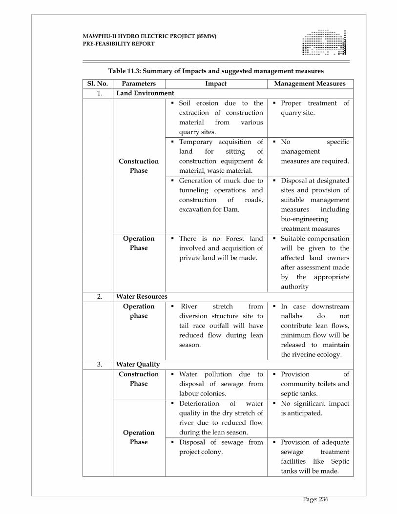
MAWPHU-II HYDRO ELECTRIC PROJECT (85MW)
MAWPHU-II HYDRO ELECTRIC PROJECT (85MW)
PRE-FEASIBILITY REPORT
Page: 236
Table 11.3: Summary of Impacts and suggested management measures
Sl. No. Parameters Impact Management Measures
1. Land Environment
Construction
Phase
� Soil erosion due to the
extraction of construction
material from various
quarry sites.
� Proper treatment of
quarry site.
� Temporary acquisition of
land for sitting of
construction equipment &
material, waste material.
� No specific
management
measures are required.
� Generation of muck due to
tunneling operations and
construction of roads,
excavation for Dam.
� Disposal at designated
sites and provision of
suitable management
measures including
bio-engineering
treatment measures
Operation
Phase
� There is no Forest land
involved and acquisition of
private land will be made.
� Suitable compensation
will be given to the
affected land owners
after assessment made
by the appropriate
authority
2. Water Resources
Operation
phase
� River stretch from
diversion structure site to
tail race outfall will have
reduced flow during lean
season.
� In case downstream
nallahs do not
contribute lean flows,
minimum flow will be
released to maintain
the riverine ecology.
3. Water Quality
Construction
Phase
� Water pollution due to
disposal of sewage from
labour colonies.
� Provision of
community toilets and
septic tanks.
Operation
Phase
� Deterioration of water
quality in the dry stretch of
river due to reduced flow
during the lean season.
� No significant impact
is anticipated.
� Disposal of sewage from
project colony.
� Provision of adequate
sewage treatment
facilities like Septic
tanks will be made.
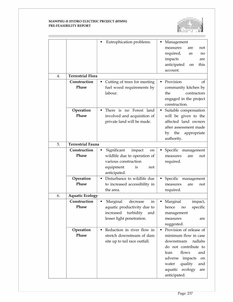
MAWPHU-II HYDRO ELECTRIC PROJECT (85MW)
MAWPHU-II HYDRO ELECTRIC PROJECT (85MW)
PRE-FEASIBILITY REPORT
Page: 237
� Eutrophication problems. � Management
measures are not
required, as no
impacts are
anticipated on this
account.
4. Terrestrial Flora
Construction
Phase
� Cutting of trees for meeting
fuel wood requirements by
labour.
� Provision of
community kitchen by
the contractors
engaged in the project
construction.
Operation
Phase
� There is no Forest land
involved and acquisition of
private land will be made.
� Suitable compensation
will be given to the
affected land owners
after assessment made
by the appropriate
authority.
5. Terrestrial Fauna
Construction
Phase
� Significant impact on
wildlife due to operation of
various-construction-
equipment is not
anticipated.
� Specific management
measures are not
required.
Operation
Phase
� Disturbance to wildlife due
to increased accessibility in
the area.
� Specific management
measures are not
required.
6. Aquatic Ecology
Construction
Phase
� Marginal decrease in
aquatic productivity due to
increased turbidity and
lesser light penetration.
� Marginal impact,
hence no specific
management
measures are
suggested.
Operation
Phase
� Reduction in river flow in
stretch downstream of dam
site up to tail race outfall.
� Provision of release of
minimum flow in case
downstream nallahs
do not contribute to
lean flows and
adverse impacts on
water quality and
aquatic ecology are
anticipated.

MAWPHU-II HYDRO ELECTRIC PROJECT (85MW)
MAWPHU-II HYDRO ELECTRIC PROJECT (85MW)
PRE-FEASIBILITY REPORT
Page: 238
7. Noise Environment
Construction
phase
� Increase in noise levels
due to operation of various
construction equipment.
� Marginal impact,
hence no management
measures are
suggested.
8. Air Environment
Construction
phase
� Increase in air pollution
due to use of machinery
and other civil activities.
� Arrangement will be
provided to minimize
air pollution from
crushers.
9. Socio-Economic Environment
Construction
Phase
� Increase in employment
potential.
---
Operation
Phase
� Increased power
generation.
---
� Greater employment
opportunities.
---
CHAPTER - XII
COST ESTIMATE
MAWPHU-II HYDRO ELECTRIC PROJECT (85MW)
MAWPHU-II HYDRO ELECTRIC PROJECT (85MW)
PRE-FEASIBILITY REPORT
Page: 239
CHAPTER - XII
PRELIMINARY COST ESTIMATE
12.1 GENERAL
The cost of the project has been worked out on the basis of preliminary designs and
drawings as referred and annexed in the present report. The unit rates for various are
taken based on available rates from similar Hydro Power Projects in the region of
Meghalaya.
12.2 BASIC ESTIMATE
12.2.1 GENERAL
The estimate has been prepared to arrive at the capital cost of Mawphu H.E. Project,
Stage - II. The base date of the estimate is April 2016. The Cost Estimate is divided into
Civil and Electrical Works. The cost estimate for Transmission works has not been
considered in this study.
12.2.2 TAXES AND DUTIES
In estimation of the cost of Civil works, E&M works, the Taxes and Duties (e.g. Excise
duty, Sales Tax, Custom Duty etc.) has been considered in the rate analysis. The cost
estimate is divided into Civil, Electrical works. For Civil Works, the sub heads are as
under:
12.2.3 I - WORKS
Under this heading, provision has been made for various components of the Project.
12.2.4 A - PRELIMINARY
The Under this heading, "provision has been made for surveys and investigations to be
conducted to arrive at the optimum of the project components.
12.2.5 B - LAND
This covers the provision for acquisition of land for construction of the project, structures,
colonies, offices etc. The provision has been kept in the estimate as per actual.
MAWPHU-II HYDRO ELECTRIC PROJECT (85MW)
MAWPHU-II HYDRO ELECTRIC PROJECT (85MW)
PRE-FEASIBILITY REPORT
Page: 240
12.2.6 C - WORKS
This covers the cost of Concrete Gravity Dam, Spillway, Coffer Dams, Diversion
Tunnel, Inlet & Outlet Portal and Plug along with associated Hydro-Mechanical
equipments.
12.2.7 J - POWER PLANT CIVIL WORKS
This covers the cost of Civil Works of Project components viz: Power Intake, Head Race
tunnel with its construction adits, Surge Shaft, Pressure Shaft, Power House, Tail race
channel & associated Hydro Mechanical equipments.
The quantities indicated in the estimates for C - Works & J-Power Plant Civil Works (Civil
& HM) are calculated from the Engineering drawings.
12.2.8 K - BUILDINGS
Buildings, both residential and non-residential have been provided under this head.
Under the permanent category only those structures have been included, which will be
subsequently utilized for the running and maintenance of the project utilities. The costs
are worked out on plinth area basis for the type of construction involved as per
prevailing rates in project area.
12.2.9 M - PLANTATION
The provision under this head covers the plantation programme including Gardens etc.
required for beautification as considered necessary downstream of Dam and
appurtenances around Power House and other important structure. The provision is
made on the lump sum basis.
12.2.10 O - MISCELLANEOUS
The provision under this head covers the capital cost & maintenance of Electrification,
Water supply, Sewage disposal and drainage works, Recreation, Medical, Fire fighting
equipments, Inspection vehicles, School bus, Pay van, Visit of dignitaries, welfare
works etc.

MAWPHU-II HYDRO ELECTRIC PROJECT (85MW)
MAWPHU-II HYDRO ELECTRIC PROJECT (85MW)
PRE-FEASIBILITY REPORT
Page: 241
12.2.11 P - MAINTENANCE DURING CONSTRUCTION & Y- LOSSES ON STOCK
The provision under this head covers the cost of maintenance of all works during the
construction period. A provision of 1% of the total cost under the heads of C-Works, J-
Power House Civil Works and K-Buildings is considered.
12.2.12 Q - SPECIAL TOOLS AND PLANT
It is assumed that the work will be carried through Contracts and accordingly provision
for general purpose equipment and inspection vehicle only has been made as per CWC
guidelines.
12.2.13 R - COMMUNICATION
Provision under this head covers the cost of construction of roads and bridges for project
works. The road widths have been planned to cater to the anticipated traffic including
carriage of equipment for the Project. The cost of roads is based on the present rate
structure prevalent in the area of the Project, for the type of construction involved.
12.2.14 X - ENVIRONMENT AND ECOLOGY
A provision has been made under this head towards Bio-diversity Conservation, Creation
of Green belt, Restoration of Construction Area, Catchment Area Treatment,
Compensatory, Afforestation etc. The provision is made on the lump sum basis.
12.2.15 Y - LOSSES ON STOCK
The provision is made at 0.25% of the total cost of C-Works, J-Power Plant Civil Works
and K-Buildings only as per the CEA Guidelines.
12.2.16 ELECTRICAL WORKS AND GENERATING PLANT
The cost of generating plant and equipment is based on sources from India. The prices of
auxiliary equipment and services are based on prevailing market prices/costs at other
ongoing or commissioned projects in India.
12.2.17 II - ESTABLISHMENT
Provision for establishment has been made @ 8% of civil works.
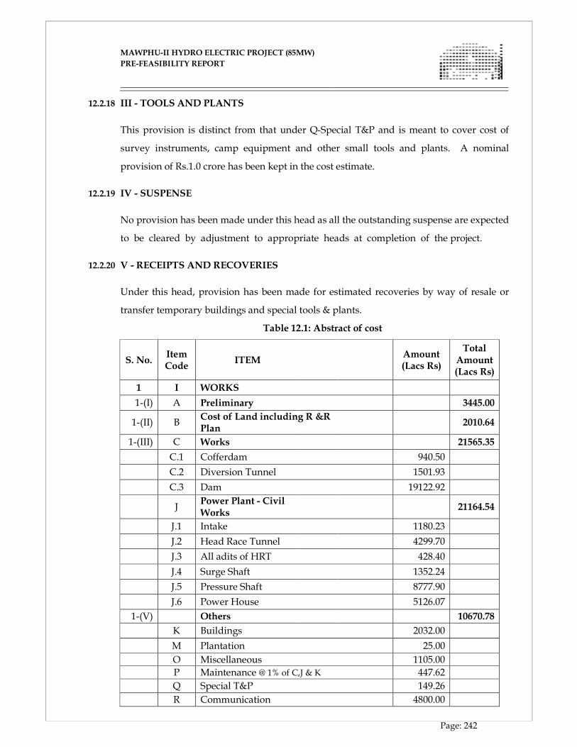
MAWPHU-II HYDRO ELECTRIC PROJECT (85MW)
MAWPHU-II HYDRO ELECTRIC PROJECT (85MW)
PRE-FEASIBILITY REPORT
Page: 242
12.2.18 III - TOOLS AND PLANTS
This provision is distinct from that under Q-Special T&P and is meant to cover cost of
survey instruments, camp equipment and other small tools and plants. A nominal
provision of Rs.1.0 crore has been kept in the cost estimate.
12.2.19 IV - SUSPENSE
No provision has been made under this head as all the outstanding suspense are expected
to be cleared by adjustment to appropriate heads at completion of the project.
12.2.20 V - RECEIPTS AND RECOVERIES
Under this head, provision has been made for estimated recoveries by way of resale or
transfer temporary buildings and special tools & plants.
Table 12.1: Abstract of cost
S. No. Item Code
ITEM Amount (Lacs Rs)
Total Amount (Lacs Rs)
1 I WORKS
1-(I) A Preliminary 3445.00
1-(II) B Cost of Land including R &R Plan
2010.64
1-(III) C Works 21565.35
C.1 Cofferdam 940.50
C.2 Diversion Tunnel 1501.93
C.3 Dam 19122.92
J Power Plant - Civil Works
21164.54
J.1 Intake 1180.23
J.2 Head Race Tunnel 4299.70
J.3 All adits of HRT 428.40
J.4 Surge Shaft 1352.24
J.5 Pressure Shaft 8777.90
J.6 Power House 5126.07
1-(V) Others 10670.78
K Buildings 2032.00
M Plantation 25.00
O Miscellaneous 1105.00
P Maintenance @ 1% of C,J & K 447.62
Q Special T&P 149.26
R Communication 4800.00

MAWPHU-II HYDRO ELECTRIC PROJECT (85MW)
MAWPHU-II HYDRO ELECTRIC PROJECT (85MW)
PRE-FEASIBILITY REPORT
Page: 243
X Environment and Ecology (*excluding establishment)
2000.00
Y Losses to Stock @ 0.25% of (C+J+K) 111.90
1 I Works (Total) 58856.31
2 II Establishment Charges @
5147.68
3 III Tools & Plants @ 100.00
4 III Receipts and Recoveries
-152.75
5 IV Indirect Charges- 394.81
(a) Audit & Accounts etc.
0.50% of I Works 294.28
(b) capitalisation of abatement of cost of land revenue (either 5% of the culturable land cost or 20 times of the annual revenue loss)
100.53
TOTAL I TO IV 64346.06
S Power Plant Electro Mechanical Works
12750.00
Power Plant, Sub-station and Transmission 12750.00
Total Cost (Civil + E&M Works) 77096.06
Interest during construction (IDC)
12085.61
Financing Charges 653.55
Escalation 4182.42
TOTAL CAPITALIZED COST OF THE PROJECT (LACS RS)
94017.64
Say 94020.00
CHAPTER - XIII
ECONOMIC AND FINANCIAL EVALUATION
MAWPHU-II HYDRO ELECTRIC PROJECT (85MW)
MAWPHU-II HYDRO ELECTRIC PROJECT (85MW)
PRE-FEASIBILITY REPORT
Page: 244
CHAPTER - XIII
ECONOMIC AND FINANCIAL EVALUATION
13.1 GENERAL
Mawphu Hydroelectric Project, Stage - II is proposed as a run-of-river scheme on the
river Umiew in East Khasi Hills District of Meghalaya. The proposed dam site is located
at about 3.1km downstream of Umduna HEP (90 MW) Power House location and the
Power House site is located at about 2km downstream of Thieddieng village on the right
bank of the river.
The Project is estimated to cost Rs. 898.38 Crore at April 2016 Price Level including Rs.
215.65 Crore on C-Civil works, Rs. 211.65 Crore on J-Works, Rs. 127.50 Crore on Electrical
Works. Completed cost of the project is Rs. 940.20 Crore with Rs. 41.82 crore as escalation
cost. Interest During Construction (IDC) on completion is Rs. 120.86 crore. Levellized
tariff of energy generated at powerhouse at bus bar has been worked out as Rs. 5.46/unit
at April 2016 P.L. (Excluding transmission cost). Corresponding tariff for first year is Rs.
5.32/unit. With completed cost, 1st year and levellised tariff stand at Rs. 5.61/unit and Rs.
5.75/unit respectively.
The benefits and financial evaluation of the project have been considered as per the
standard guidelines issued by the Government of India. The norms laid down by the
Central Electricity Regulatory Commission (CERC) for Hydro projects have also been
kept in view in this regard.
13.2 PROJECT COST
The cost of construction of the project has been estimated at April 2016 price level with a
construction period of 60 months. The estimated Present Day Cost of the project is Rs.
892.57 crore, including Rs. 770.96 crore of Hard Cost and Rs. 121.61crore as IDC &
financial charges at April 2016 price level. Total completed cost of the project stands at Rs.
940.20 crore with Rs. 127.39 crore as cost towards IDC and financial charges. The
completion cost is based on the tentative financial assessment and it may vary based on
firm financial package.
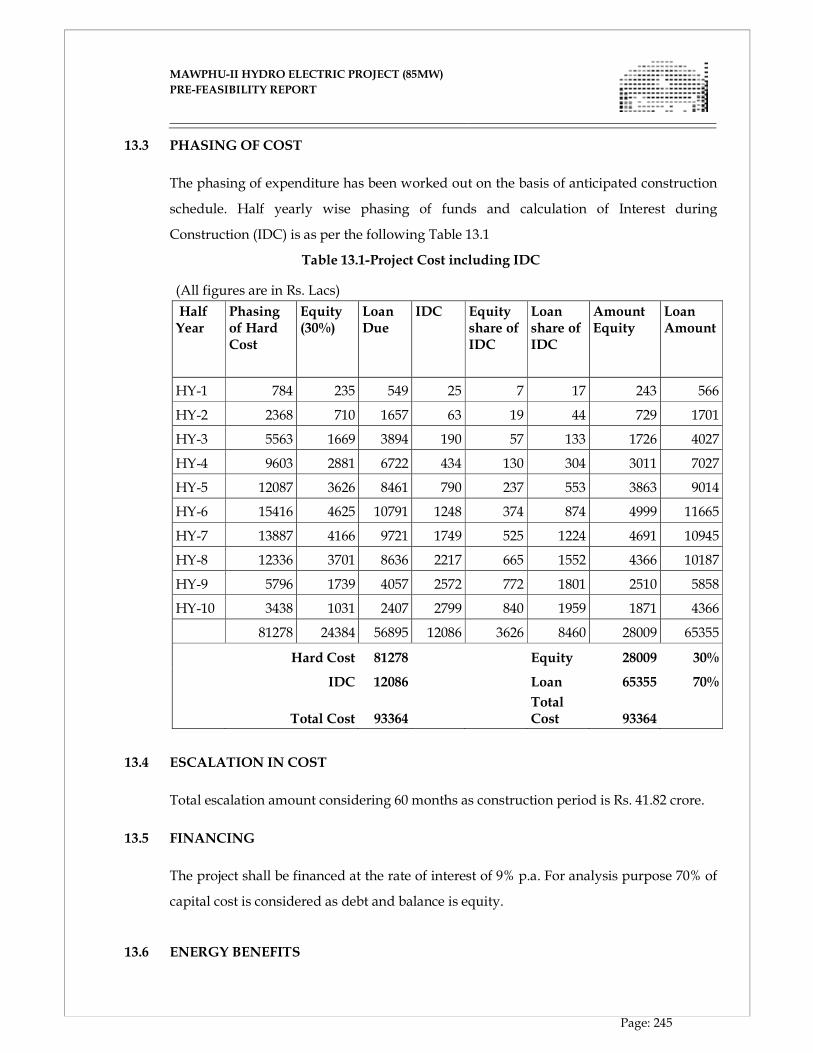
MAWPHU-II HYDRO ELECTRIC PROJECT (85MW)
MAWPHU-II HYDRO ELECTRIC PROJECT (85MW)
PRE-FEASIBILITY REPORT
Page: 245
13.3 PHASING OF COST
The phasing of expenditure has been worked out on the basis of anticipated construction
schedule. Half yearly wise phasing of funds and calculation of Interest during
Construction (IDC) is as per the following Table 13.1
Table 13.1-Project Cost including IDC
(All figures are in Rs. Lacs) Half
Year Phasing of Hard Cost
Equity (30%)
Loan Due
IDC Equity share of IDC
Loan share of IDC
Amount Equity
Loan Amount
HY-1 784 235 549 25 7 17 243 566
HY-2 2368 710 1657 63 19 44 729 1701
HY-3 5563 1669 3894 190 57 133 1726 4027
HY-4 9603 2881 6722 434 130 304 3011 7027
HY-5 12087 3626 8461 790 237 553 3863 9014
HY-6 15416 4625 10791 1248 374 874 4999 11665
HY-7 13887 4166 9721 1749 525 1224 4691 10945
HY-8 12336 3701 8636 2217 665 1552 4366 10187
HY-9 5796 1739 4057 2572 772 1801 2510 5858
HY-10 3438 1031 2407 2799 840 1959 1871 4366
81278 24384 56895 12086 3626 8460 28009 65355
Hard Cost 81278 Equity 28009 30%
IDC 12086 Loan 65355 70%
Total Cost 93364 Total Cost 93364
13.4 ESCALATION IN COST
Total escalation amount considering 60 months as construction period is Rs. 41.82 crore.
13.5 FINANCING
The project shall be financed at the rate of interest of 9% p.a. For analysis purpose 70% of
capital cost is considered as debt and balance is equity.
13.6 ENERGY BENEFITS
MAWPHU-II HYDRO ELECTRIC PROJECT (85MW)
MAWPHU-II HYDRO ELECTRIC PROJECT (85MW)
PRE-FEASIBILITY REPORT
Page: 246
The financial analysis is based on the energy output on 90% dependable year at 95% plant
availability. 1.0% auxiliary consumption has been considered in preliminary financial
evaluation of the project. For the purpose of calculation of tariff the free power has been
considered as per provisions of CERC norms.
13.7 ENERGY SALE PRICE
The energy tariff has been worked out as per practice with 15.50% return on equity. The
same has been used for sale of the energy.
13.8 THE ASSUMPTIONS TAKEN FOR WORKING OUT THE TARIFF ARE AS
FOLLOWS:
13.8.1 PROJECT LIFE
The project life has been taken as 35 years for all the above cases as per prevailing Indian
Hydropower policy.
13.8.2 INTEREST RATE
The interest rate of 9.00% has been reckoned for working out the financial return. The
interest during construction has also been capitalized as 70% loan and 30% equity.
13.8.3 RETURN ON EQUITY
For working out the unit cost of energy, the return on equity has been taken at 15.5% as
per prevailing practice of Govt. of India.
13.8.4 DEPRECIATION
Uniform depreciation @ 2.56% per annum has been considered for initial 28 years. For
remaining 7 years, the balance depreciation i.e.90% of total project cost minus land cost
has been equally spread out.
13.8.5 OPERATION AND MAINTENANCE CHARGES
2.0% of capital cost has been taken for operation and maintenance charges with an annual
escalation of 6.64%.
13.8.6 INTEREST ON WORKING CAPITAL
MAWPHU-II HYDRO ELECTRIC PROJECT (85MW)
MAWPHU-II HYDRO ELECTRIC PROJECT (85MW)
PRE-FEASIBILITY REPORT
Page: 247
Interest on Working Capital has been calculated as given below:
(i) Receivables equivalent to two months of fixed cost;
(ii) Maintenance spares @ 15% of operation and maintenance expenses and
(iii) Operation and maintenance expenses for one month.
13.8.7 AUXILIARY AND TRANSFORMATION LOSSES
The auxiliary and transformation losses have been taken as 1.0% of the design energy in
90% dependable year. (Design Energy= 331MU, Unit Sold = 283.34*(1-1.0%) =327.69MU)
13.8.8 OTHER MISCELLANEOUS ASSUMPTIONS
• Interest rate on Working Capital = 12.80%
• Discounting Rate = 12.07%
• Tenure for Loan Repayment = 28 Years
• Corporate tax is taken as 34.61% and Minimum alternate Tax is taken as
21.34% as per Govt. of India Hydropower Policy.
13.8.9 TARIFF COMPUTATION
With above assumptions the tariff for the project for 90% dependable year comes out to
be:
Present day cost (PL April 2016)
1st year = Rs. 5.32/unit
Levellized tariff: - Rs. 5.46/unit
Completed cost
1st year = Rs. 5.61/unit
Levellized tariff: - Rs. 5.75/unit
Refer Annexure 13.1 & 13.2 for tariff computations.

MAWPHU-II HYDRO ELECTRIC PROJECT (85MW)
MAWPHU-II HYDRO ELECTRIC PROJECT (85MW)
PRE-FEASIBILITY REPORT
Page: i
Calculation of Tariff (Price Level April’2016) Annexure-13.1 Annual Design Energy
(MU)
= 331.00 Cost incl IDC (Rs Cr)
= 892.57 FI Loan and bond (Rs. Cr.)
= 624.80
Auxilary Loss (%) = 1.00% Equity (Rs Cr)
= 267.77 Loan and Bond Interest
= 9.00%
Free Power (%)
= 13.00% Interest on W.C.
= 12.80% Subordinate Loan (Rs. Cr.)
= 0.00
Net Saleable Energy (MU) = 285.09 Grant (Rs. Cr.) = 0.00 Subordinate Loan Interest
= 1.00%
Land Cost (Rs.
Crores)
= 20.41 O&M Charges
= 2.00%
Cost of R&R (Rs.crore)
= 10.15 Avg. Depriciation
Rate
= 2.56% Return on Equity (RoE)
= 15.50%
Discounting Factor = 12.07% Min Alternate Tax(MAT) = 21.34%
FI Loan Repayment
Period (Year)
= 28.00 Corporate Tax = 34.61%
SB Repayment Period
(Year)
= 15.00 Return on Equity (RoE) with MAT = 19.705%
Return on Equity (RoE) with Corporate
Tax
= 23.703%
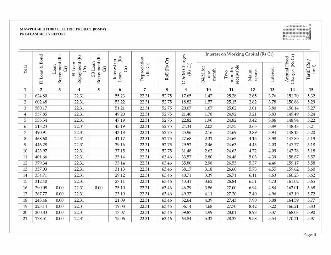
MAWPHU-II HYDRO ELECTRIC PROJECT (85MW)
MAWPHU-II HYDRO ELECTRIC PROJECT (85MW)
PRE-FEASIBILITY REPORT
Page: ii
Year
FI Loan
& Bond
Loan
Rep
aymen
t (R
s
Cr)
FI Loan
Rep
aymen
t (R
s
Cr)
SB Loan
Rep
aymen
t (R
s
Cr)
Interest on
Loan
(Rs
Cr)
Dep
reciation
(Rs Cr)
RoE (Rs Cr)
O &
M Charges
(Rs Cr)
Interest on Working Capital (Rs Cr)
Annual Fixed
Charges (Rs Cr)
Tariff (R
s /
unit)
O&M for
one
month
Two
month's
receivab
le
Maint.
spares
Interest
1 2 3 4 5 6 7 8 9 10 11 12 13 14 15
1 624.80 22.31 55.23 22.31 52.75 17.65 1.47 25.28 2.65 3.76 151.70 5.32
2 602.48 22.31 53.22 22.31 52.75 18.82 1.57 25.15 2.82 3.78 150.88 5.29
3 580.17 22.31 51.21 22.31 52.75 20.07 1.67 25.02 3.01 3.80 150.14 5.27
4 557.85 22.31 49.20 22.31 52.75 21.40 1.78 24.92 3.21 3.83 149.49 5.24
5 535.54 22.31 47.19 22.31 52.75 22.82 1.90 24.82 3.42 3.86 148.94 5.22
6 513.23 22.31 45.19 22.31 52.75 24.34 2.03 24.75 3.65 3.89 148.48 5.21
7 490.91 22.31 43.18 22.31 52.75 25.96 2.16 24.69 3.89 3.94 148.13 5.20
8 468.60 22.31 41.17 22.31 52.75 27.68 2.31 24.65 4.15 3.98 147.89 5.19
9 446.28 22.31 39.16 22.31 52.75 29.52 2.46 24.63 4.43 4.03 147.77 5.18
10 423.97 22.31 37.15 22.31 52.75 31.48 2.62 24.63 4.72 4.09 147.78 5.18
11 401.66 22.31 35.14 22.31 63.46 33.57 2.80 26.48 5.03 4.39 158.87 5.57
12 379.34 22.31 33.14 22.31 63.46 35.80 2.98 26.53 5.37 4.46 159.17 5.58
13 357.03 22.31 31.13 22.31 63.46 38.17 3.18 26.60 5.73 4.55 159.62 5.60
14 334.71 22.31 29.12 22.31 63.46 40.71 3.39 26.71 6.11 4.63 160.23 5.62
15 312.40 22.31 27.11 22.31 63.46 43.41 3.62 26.84 6.51 4.73 161.02 5.65
16 290.08 0.00 22.31 0.00 25.10 22.31 63.46 46.29 3.86 27.00 6.94 4.84 162.01 5.68
17 267.77 0.00 22.31 23.10 22.31 63.46 49.37 4.11 27.20 7.40 4.96 163.19 5.72
18 245.46 0.00 22.31 21.09 22.31 63.46 52.64 4.39 27.43 7.90 5.08 164.59 5.77
19 223.14 0.00 22.31 19.08 22.31 63.46 56.14 4.68 27.70 8.42 5.22 166.21 5.83
20 200.83 0.00 22.31 17.07 22.31 63.46 59.87 4.99 28.01 8.98 5.37 168.08 5.90
21 178.51 0.00 22.31 15.06 22.31 63.46 63.84 5.32 28.37 9.58 5.54 170.21 5.97
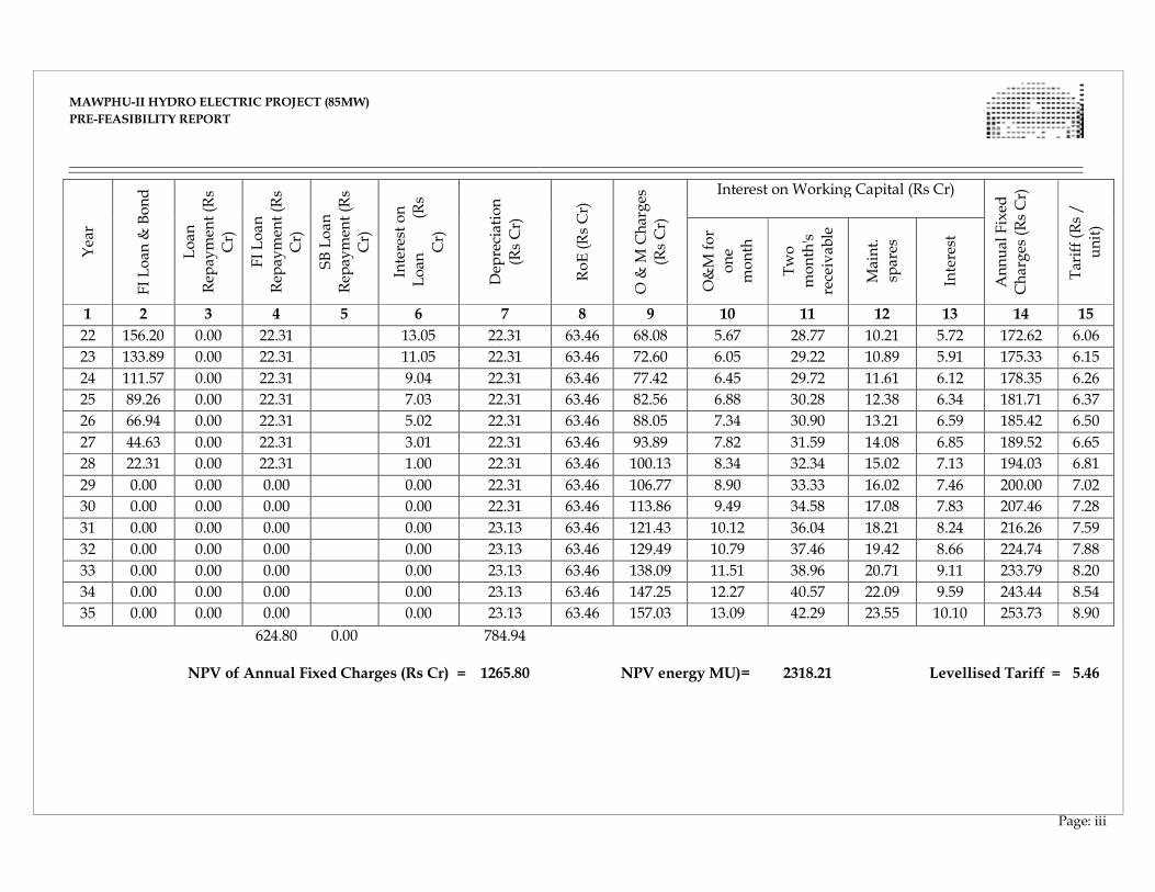
MAWPHU-II HYDRO ELECTRIC PROJECT (85MW)
MAWPHU-II HYDRO ELECTRIC PROJECT (85MW)
PRE-FEASIBILITY REPORT
Page: iii
Year
FI Loan
& Bond
Loan
Rep
aymen
t (R
s
Cr)
FI Loan
Rep
aymen
t (R
s
Cr)
SB Loan
Rep
aymen
t (R
s
Cr)
Interest on
Loan
(Rs
Cr)
Dep
reciation
(Rs Cr)
RoE (Rs Cr)
O &
M Charges
(Rs Cr)
Interest on Working Capital (Rs Cr)
Annual Fixed
Charges (Rs Cr)
Tariff (R
s /
unit)
O&M for
one
month
Two
month's
receivab
le
Maint.
spares
Interest
1 2 3 4 5 6 7 8 9 10 11 12 13 14 15
22 156.20 0.00 22.31 13.05 22.31 63.46 68.08 5.67 28.77 10.21 5.72 172.62 6.06
23 133.89 0.00 22.31 11.05 22.31 63.46 72.60 6.05 29.22 10.89 5.91 175.33 6.15
24 111.57 0.00 22.31 9.04 22.31 63.46 77.42 6.45 29.72 11.61 6.12 178.35 6.26
25 89.26 0.00 22.31 7.03 22.31 63.46 82.56 6.88 30.28 12.38 6.34 181.71 6.37
26 66.94 0.00 22.31 5.02 22.31 63.46 88.05 7.34 30.90 13.21 6.59 185.42 6.50
27 44.63 0.00 22.31 3.01 22.31 63.46 93.89 7.82 31.59 14.08 6.85 189.52 6.65
28 22.31 0.00 22.31 1.00 22.31 63.46 100.13 8.34 32.34 15.02 7.13 194.03 6.81
29 0.00 0.00 0.00 0.00 22.31 63.46 106.77 8.90 33.33 16.02 7.46 200.00 7.02
30 0.00 0.00 0.00 0.00 22.31 63.46 113.86 9.49 34.58 17.08 7.83 207.46 7.28
31 0.00 0.00 0.00 0.00 23.13 63.46 121.43 10.12 36.04 18.21 8.24 216.26 7.59
32 0.00 0.00 0.00 0.00 23.13 63.46 129.49 10.79 37.46 19.42 8.66 224.74 7.88
33 0.00 0.00 0.00 0.00 23.13 63.46 138.09 11.51 38.96 20.71 9.11 233.79 8.20
34 0.00 0.00 0.00 0.00 23.13 63.46 147.25 12.27 40.57 22.09 9.59 243.44 8.54
35 0.00 0.00 0.00 0.00 23.13 63.46 157.03 13.09 42.29 23.55 10.10 253.73 8.90
624.80
0.00 784.94
NPV of Annual Fixed Charges (Rs Cr) = 1265.80 NPV energy MU)= 2318.21 Levellised Tariff = 5.46
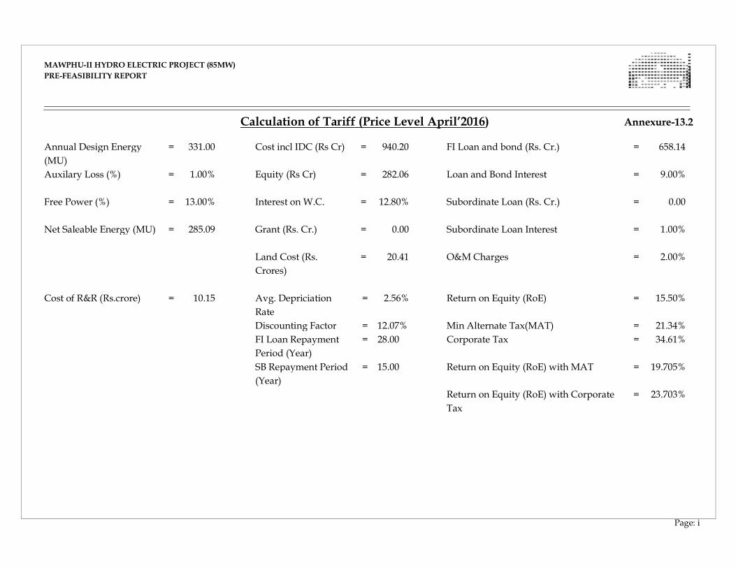
MAWPHU-II HYDRO ELECTRIC PROJECT (85MW)
MAWPHU-II HYDRO ELECTRIC PROJECT (85MW)
PRE-FEASIBILITY REPORT
Page: i
Calculation of Tariff (Price Level April’2016) Annexure-13.2 Annual Design Energy
(MU)
= 331.00 Cost incl IDC (Rs Cr)
= 940.20 FI Loan and bond (Rs. Cr.)
= 658.14
Auxilary Loss (%) = 1.00% Equity (Rs Cr)
= 282.06 Loan and Bond Interest
= 9.00%
Free Power (%)
= 13.00% Interest on W.C.
= 12.80% Subordinate Loan (Rs. Cr.)
= 0.00
Net Saleable Energy (MU) = 285.09 Grant (Rs. Cr.) = 0.00 Subordinate Loan Interest
= 1.00%
Land Cost (Rs.
Crores)
= 20.41 O&M Charges
= 2.00%
Cost of R&R (Rs.crore)
= 10.15 Avg. Depriciation
Rate
= 2.56% Return on Equity (RoE)
= 15.50%
Discounting Factor = 12.07% Min Alternate Tax(MAT) = 21.34%
FI Loan Repayment
Period (Year)
= 28.00 Corporate Tax = 34.61%
SB Repayment Period
(Year)
= 15.00 Return on Equity (RoE) with MAT = 19.705%
Return on Equity (RoE) with Corporate
Tax
= 23.703%
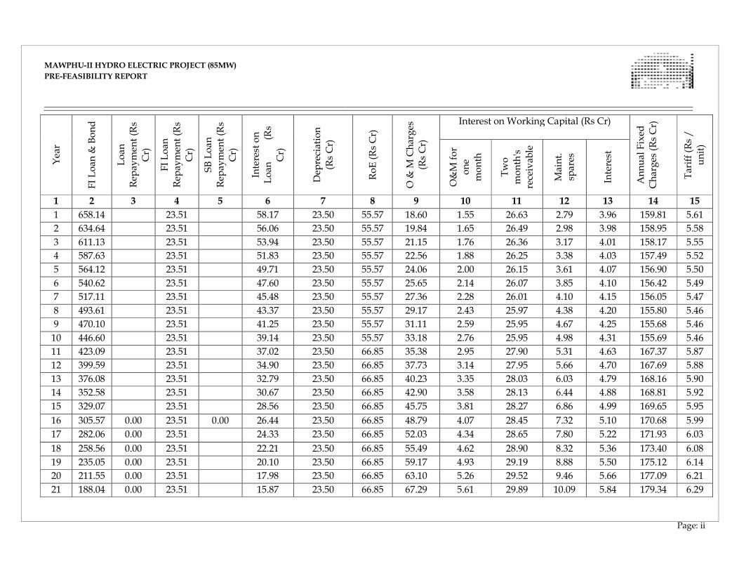
MAWPHU-II HYDRO ELECTRIC PROJECT (85MW)
MAWPHU-II HYDRO ELECTRIC PROJECT (85MW)
PRE-FEASIBILITY REPORT
Page: ii
Year
FI Loan
& Bond
Loan
Rep
aymen
t (R
s
Cr)
FI Loan
Rep
aymen
t (R
s
Cr)
SB Loan
Rep
aymen
t (R
s
Cr)
Interest on
Loan
(Rs
Cr)
Dep
reciation
(Rs Cr)
RoE (Rs Cr)
O &
M Charges
(Rs Cr)
Interest on Working Capital (Rs Cr)
Annual Fixed
Charges (Rs Cr)
Tariff (R
s /
unit)
O&M for
one
month
Two
month's
receivab
le
Maint.
spares
Interest
1 2 3 4 5 6 7 8 9 10 11 12 13 14 15
1 658.14 23.51 58.17 23.50 55.57 18.60 1.55 26.63 2.79 3.96 159.81 5.61
2 634.64 23.51 56.06 23.50 55.57 19.84 1.65 26.49 2.98 3.98 158.95 5.58
3 611.13 23.51 53.94 23.50 55.57 21.15 1.76 26.36 3.17 4.01 158.17 5.55
4 587.63 23.51 51.83 23.50 55.57 22.56 1.88 26.25 3.38 4.03 157.49 5.52
5 564.12 23.51 49.71 23.50 55.57 24.06 2.00 26.15 3.61 4.07 156.90 5.50
6 540.62 23.51 47.60 23.50 55.57 25.65 2.14 26.07 3.85 4.10 156.42 5.49
7 517.11 23.51 45.48 23.50 55.57 27.36 2.28 26.01 4.10 4.15 156.05 5.47
8 493.61 23.51 43.37 23.50 55.57 29.17 2.43 25.97 4.38 4.20 155.80 5.46
9 470.10 23.51 41.25 23.50 55.57 31.11 2.59 25.95 4.67 4.25 155.68 5.46
10 446.60 23.51 39.14 23.50 55.57 33.18 2.76 25.95 4.98 4.31 155.69 5.46
11 423.09 23.51 37.02 23.50 66.85 35.38 2.95 27.90 5.31 4.63 167.37 5.87
12 399.59 23.51 34.90 23.50 66.85 37.73 3.14 27.95 5.66 4.70 167.69 5.88
13 376.08 23.51 32.79 23.50 66.85 40.23 3.35 28.03 6.03 4.79 168.16 5.90
14 352.58 23.51 30.67 23.50 66.85 42.90 3.58 28.13 6.44 4.88 168.81 5.92
15 329.07 23.51 28.56 23.50 66.85 45.75 3.81 28.27 6.86 4.99 169.65 5.95
16 305.57 0.00 23.51 0.00 26.44 23.50 66.85 48.79 4.07 28.45 7.32 5.10 170.68 5.99
17 282.06 0.00 23.51 24.33 23.50 66.85 52.03 4.34 28.65 7.80 5.22 171.93 6.03
18 258.56 0.00 23.51 22.21 23.50 66.85 55.49 4.62 28.90 8.32 5.36 173.40 6.08
19 235.05 0.00 23.51 20.10 23.50 66.85 59.17 4.93 29.19 8.88 5.50 175.12 6.14
20 211.55 0.00 23.51 17.98 23.50 66.85 63.10 5.26 29.52 9.46 5.66 177.09 6.21
21 188.04 0.00 23.51 15.87 23.50 66.85 67.29 5.61 29.89 10.09 5.84 179.34 6.29
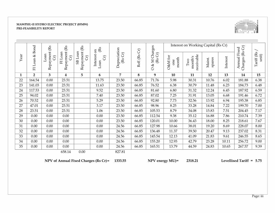
MAWPHU-II HYDRO ELECTRIC PROJECT (85MW)
MAWPHU-II HYDRO ELECTRIC PROJECT (85MW)
PRE-FEASIBILITY REPORT
Page: iii
Year
FI Loan
& Bond
Loan
Rep
aymen
t (R
s
Cr)
FI Loan
Rep
aymen
t (R
s
Cr)
SB Loan
Rep
aymen
t (R
s
Cr)
Interest on
Loan
(Rs
Cr)
Dep
reciation
(Rs Cr)
RoE (Rs Cr)
O &
M Charges
(Rs Cr)
Interest on Working Capital (Rs Cr)
Annual Fixed
Charges (Rs Cr)
Tariff (R
s /
unit)
O&M for
one
month
Two
month's
receivab
le
Maint.
spares
Interest
1 2 3 4 5 6 7 8 9 10 11 12 13 14 15
22 164.54 0.00 23.51 13.75 23.50 66.85 71.76 5.98 30.31 10.76 6.02 181.88 6.38
23 141.03 0.00 23.51 11.63 23.50 66.85 76.52 6.38 30.79 11.48 6.23 184.73 6.48
24 117.53 0.00 23.51 9.52 23.50 66.85 81.60 6.80 31.32 12.24 6.45 187.92 6.59
25 94.02 0.00 23.51 7.40 23.50 66.85 87.02 7.25 31.91 13.05 6.68 191.46 6.72
26 70.52 0.00 23.51 5.29 23.50 66.85 92.80 7.73 32.56 13.92 6.94 195.38 6.85
27 47.01 0.00 23.51 3.17 23.50 66.85 98.96 8.25 33.28 14.84 7.22 199.70 7.00
28 23.51 0.00 23.51 1.06 23.50 66.85 105.53 8.79 34.08 15.83 7.51 204.45 7.17
29 0.00 0.00 0.00 0.00 23.50 66.85 112.54 9.38 35.12 16.88 7.86 210.74 7.39
30 0.00 0.00 0.00 0.00 23.50 66.85 120.01 10.00 36.43 18.00 8.25 218.61 7.67
31 0.00 0.00 0.00 0.00 24.56 66.85 127.98 10.66 38.01 19.20 8.69 228.07 8.00
32 0.00 0.00 0.00 0.00 24.56 66.85 136.48 11.37 39.50 20.47 9.13 237.02 8.31
33 0.00 0.00 0.00 0.00 24.56 66.85 145.54 12.13 41.09 21.83 9.61 246.55 8.65
34 0.00 0.00 0.00 0.00 24.56 66.85 155.20 12.93 42.79 23.28 10.11 256.72 9.00
35 0.00 0.00 0.00 0.00 24.56 66.85 165.51 13.79 44.59 24.83 10.65 267.57 9.39
658.14
0.00 827.81
NPV of Annual Fixed Charges (Rs Cr) = 1333.55 NPV energy MU)= 2318.21 Levellised Tariff = 5.75