Embed Size (px)
Citation preview

1
Materials Handling Accident Reduction in Underground Mines
Bill M. Stewart, Curtis Clark, and Phil PattonSpokane Research Laboratory, National Institution for Occupational Safety and
Health, E. 315 Montgomery, Spokane, WA 99207(509)354-8021 office(509)354-8099 fax
2
Synopsis
Handling materials in underground mines continues to be a major safety problem. Tohelp reduce materials-handling injuries, the National Institute for Occupational Safetyand Health (NIOSH) at the Spokane Research Laboratory is developing, modifying, andtesting equipment to replace the necessity of doing lifting tasks manually. To reducesingle-event lift injuries, equipment having mechanical automatic weight sensing andbalancing control was investigated. The Coleman manipulator was selected for testing.Modifications to the Coleman manipulator to make it more suitable for undergroundmine use included mobilization, self-containment, all-purpose gripper attachment, andsupport jacks.
To reduce or eliminate the need to clean off manually the materials that commonly pluggrizzly openings (timbers, wire mesh, roof bolts, and other debris), a track-guidedpincher arm device was developed. The TGPA attaches to an impact hammer head, andthe pincher arms are controlled by the operator of the hammer. Oversized rock can bebroken with the pincher arms in the up position; the arms can then be lowered to graband remove debris. Sweeping action to remove cohesive fines bridging grizzlyopenings is also greatly improved. This device is especially useful in recessed grizzlies.
An industrial gun was tested to evaluate its effectiveness in breaking oversized rock.Boulders up to 76 cm in diameter were successfully broken to minus-33 cm. Althoughmethods to control flyrock need to be developed, an industrial gun may be a safe andinexpensive alternative to breaking oversized rock in certain underground miningsituations.
Keywords: Mining, materials handling, overexertion, injuries
3
Introduction
Materials-handling problems in underground mines and injuries associated withunderground materials handling have been well documented . Although lost-workday1, 2
injury rates related to materials handling in mines decreased between 1988 and 1997 ,3.4
the number of lost workdays was still significant, and the cost to the mining industryeach year was tremendous. During that time, there were 58,661 lost-workday casesresulting in an average of 34 days lost (including restricted days) per case. Over 21,000of the lost-workday cases were in underground mines.
Reviewing data from 1998-1999 from the 20 underground mines investigated in thisstudy indicated that materials handling was still the leading cause of reportable injuries.Accident report narratives showed numerous and varied materials-handling activitiesthat resulted in injuries. This finding is not much different from what was reported in1989 in an extensive investigation of back injuries in underground coal mines . The5
authors of that report found “considerable diversity in the situations which produce backinjuries. Of the 156 scenarios which produced back injuries, 130 occurred only once,17 occurred twice, 4 occurred three times, 1 occurred six times, 2 occurred eight times,and 2 occurred 10 or more times.”
Given the nature of the underground environment (poor lighting, poor footing, confinedspaces, etc.), the amount of supplies and equipment needed daily, and the diversity oftasks, injuries resulting from materials handling will probably never be eliminated. Thenumber of such injuries is directly related to the number of manual tasks. Hundreds ofthese tasks are performed in underground mines each day. They involve pulling,hanging, pushing, and lifting objects of different weights, shapes, and sizes. Manytimes, handling tasks are done in confined areas, on uneven ground, in slipperyconditions, and without assistance.
Large underground mines have fewer materials-handling accidents than smaller mines,because in large mines, there is room for mechanized equipment. However, mostunderground mines have limited space. Numerous materials-handling tasks can onlybe done manually, and lifting and relifting supplies several times before they are usedis not uncommon.
In the 1980's, several inexpensive, easy-to-construct, materials-handling devices weredeveloped and tested for underground mines . These devices included a scoop-mounted6
lift boom for transporting and maneuvering heavy machine components, a swing armboom to lift components on and off transport vehicles, a floor-type maintenance jackfor lifting heavy machine parts, a mine mud car to aid in moving supplies from storageareas to the point of use, a container workstation vehicle to transport tools and supplieson a daily basis, and a timber car for installing crossbeams for roof support. All of thesedevices were designed to reduce materials-handling injuries. Research to reduceinjuries from specific materials-handling tasks, such as hanging cables, building
4
stoppings, and handling bags of rock dust, was also conducted .7
The goal of this research project is to reduce materials-handling injuries by reducingmanual materials-handling tasks. This paper describes the development and testing ofspecialized equipment to help achieve that goal.
Description of Problems
The research approach is to investigate common underground materials-handling tasksor activities that frequently result in injuries and that occur in several different mines.Only coal and metal underground mines were included in this research. Emphasis wasplaced on manual tasks. The focus areas were determined by reviewing MSHAaccident report narratives, personal discussions with mine safety officers, and minetours to witness materials-handling activities. The 10 most common materials-handlingactivities that resulted in reportable injuries numerous times in 1999 and theapproximate number of occurrences are shown in Table 1. Some are unique to metalmines, some to coal mines, and some are common in both types of mines. Because ofbudget and time constraints, it was not possible to develop and/or test solutions to allcommon materials-handling problems. Detailed investigations described in this paperinclude methods to reduce injuries from three activities: single lifting event, cleaningdebris from grizzlies, and breaking oversized rocks. Investigations included the use ofexisting equipment, modifications of existing equipment, and development of newequipment.
Table 1– Underground materials-handling activities and number of injuries in 1999 (MSHA,
2000)
Activity No. of occurrences
Moving cable (primarily trailing cable) . . . . . . . . . . . . . . . . . . . . 117
Moving roof bolt supplies . . . . . . . . . . . . . . . . . . . . . . . . . . . . . . 85
Moving conveyor belt parts . . . . . . . . . . . . . . . . . . . . . . . . . . . . . 69
Loading/unloading supplies in and out of carriers . . . . . . . . . . . 50
Moving roof support supplies (timbers, beams, cribs, etc.) . . . . 25
Construction activities (stopping, bulkheads, overcasts, etc) . . . 25
Moving rock dust supplies . . . . . . . . . . . . . . . . . . . . . . . . . . . . . 23
Lifting, hanging, pulling objects overhead . . . . . . . . . . . . . . . . . 23
Moving, shoveling rock, coal, debris . . . . . . . . . . . . . . . . . . . . . 16
Moving pumps . . . . . . . . . . . . . . . . . . . . . . . . . . . . . . . . . . . . . . 11
Single Lifting Event
Lifting and pulling activities associated with materials handling in underground minescontinue to account for a significant percentage of back injuries. This is depicted
5
graphically in Figure 1. Most of these back injuries are thought to have occurred in asituation where, for reasons of expediency and in the absence of help, the worker triedto lift materials or handle equipment that was too heavy.
Assisted lift devices (manipulators) are currently used in many manufacturing sectorsto reduce injuries associated with manual equipment and materials handling.Manipulators allow workers to lift and maneuver heavy objects throughout a workenvelope, yet require that the operator exert only a few pounds of force. Undergroundshop areas where a variety of lifting activities occur in the course of performingmaintenance activities are particularly good candidates for assisted lifting devices.Handling large pneumatic wheel-lug wrenches and changing out hydraulic motors areexamples of maintenance-related lifting activities and involve lifting, positioning, andsometimes holding heavy objects.
Handling materials being dispersed from laydown areas to the work areas is a goodcandidate for assisted lift devices. In most underground mines, getting needed materialsfrom the surface to underground laydown areas is done with forklifts or othermechanized devices. The materials are generally placed on a pallet and tied together.Once in the laydown area, however, materials are separated and must be handledmanually by workers for each shift.
Other applications of assisted lifting involve maintenance of heavy equipment whereno overhead lifting system is in place, such as conveyor belt systems in undergroundmines, which are often manually disassembled, moved and reassembled. Use ofmanipulators for bulkheads, overcasts, and stopping construction and for hangingsupplies (waterlines, ventilation tubes, etc.) from the mine back is another possibility.
Cleaning Debris from Grizzlies
Grizzlies are used in underground mines to prevent large boulders from entering orepasses and causing obstructions. Some grizzlies are installed at ground level and othersare recessed below ground level to accommodate sidecar or truck dumping. Typically,grizzly surfaces become clogged by the oversized boulders they are designed to retain;by fine cohesive materials that bridge openings; and by roof bolts, timbers, wire mesh,and other debris that have broken away and mixed with the mined ore. Impact hammersare effective in breaking oversized rock, but are very limited in cleaning off fines andare incapable of removing debris. In some hard-rock mines, especially those withrecessed grizzlies, oversized rock is broken using permanently mounted hydraulicimpact hammers. The hammer head is mounted on a backhoe-type arm and iscontrolled remotely from a control panel. In mines with accessible ground-levelgrizzlies, oversized rock is scooped from the grizzly and broken by secondary blastingand/or crushing. In some mines without impact hammers, the rock is broken manuallywith a double-jack sledgehammer. Roof bolts, timbers, wire mesh, and other debris aregenerally removed by a worker who climbs onto the grizzly and throws the debris off
6
to the side, which is especially difficult in recessed grizzlies. The materials then has tobe picked up, placed in the trash, and hauled to the surface or other undergrounddisposal area.
Rock Breaking
Manually breaking oversize rock and removing debris from grizzlies is a hazardous taskand has resulted in many injuries. A recent MSHA database search (1987 to 1996) foraccidents and fatalities associated with ore passes in underground metal minesidentified 78 accidents (of 392, or 20 per cent) as being caused by manually breakingand cleaning rock from grizzlies. These accidents included cuts and abrasions requiringstitches because of fragmentation of rock and metal pieces (12 incidents); injuries to theback, neck, and arm muscles (13 incidents); slip and falls (11 incidents, one of whichresulted in a permanent disability); rock movements that caused pinched and brokenfeet, fingers, hands ankles, and head injuries (26 incidents); and bar and hammerricochet injuries (16 incidents).
Unless drilling and applying a breaking agent can be done remotely, oversized rock hasto be removed from the ore prior to dumping, removed from the grizzly after dumping(not feasible in recessed grizzlies), or drilled by a miner going onto the grizzly. Thesealternatives, although effective, can be time consuming, hazardous (if person has to goonto grizzly to drill), or expensive.
On the basis of this information, it is apparent that breaking rock and cleaning grizzliesshould be done by machinery and that a worker be allowed to work on a grizzly in anactive pass only as a last resort.
Investigations at the Spokane Research Laboratory
Manipulators
After purchasing a standard manipulator (Figure 2), Spokane Research Laboratory(SRL) personnel conducted a series of typical lifting activities to determine baselineperformance. The device operated as intended with regard to lifting; however, severalfunctional limitations and operational capabilities were identified as needingimprovement before the device would be practical. The most significant limitation waslack of mobility. With a weighted pallet jack base of 680 kg, the manipulator was tooheavy for one person to move and position. A second limitation was lack of stabilityand leveling capability; that is, the device would rock on two of its four contact pads ifthe floor had any uneven or low spots. The manipulator arm would also list to the lowside of a flat, but inclined floor. A third limitation was the height and length of the unit,which made it difficult to move from one work area to another. Doorways weredifficult to pass through because of the height, and corners were hard to navigate aroundbecause of the length.
7
Mention of specific products or manufacturers does not imply endorsement by the National Institute1
for Occupational Safety and Health.
Thus, researchers decided to modify the manipulator to improve its basic function. Forthe device to be practical, it would have to be self-propelled, compact enough to fitthrough openings and around corners, and stable and level once positioned. Also, thedevice would need to be self-contained with regard to the air and electrical supply forthe lifting/driving/leveling system. An integrated design incorporating the manipulatorwas designed and named the mobile manipulator system (MMS).
Engineering design for the MMS involved modifications to the manipulator arm and thedevelopment of several subsystems that form the basis of the MMS. The MMS will becomposed of a manipulator mounted on a mobile base. The base will be equipped withtelescoping outrigger stabilizers and independently controlled leveling legs. In addition,an air compressor, inverter, and battery system will also be mounted on the mobile unit.
These individual components will form the basis of an integral lifting system. Theresulting MMS will be trammed to the location needed, deploy outriggers, level the baseunit, then operate via the self-contained air-hydraulic system, all in a timely manner andrequiring only a single user/operator. An artist’s concept of the MMS is shown inFigure 3. If the baseline performance is satisfactory, then the device will undergo aseries of tests designed to approximate the manual materials handling and maintenanceactivities in mining environments.
Industrial Gun
There are numerous secondary blasting methods that break oversized rock effectively.Most require a hole to be drilled part way through the rock in which the breaking agentis applied. At least two commercial machines have been developed that can drill andblast rock remotely or from the end of a boom at some distance from the rock. One isthe “Weasel,” a remote-controlled hole drilling and blasting vehicle manufactured byMarcotte Mining, Sudbury, ON. The other is the Ro-Bust System, manufactured by1
McCarthy Industries, Ltd., Denver, CO, which uses a percussive drill and a Ro-Bustpulse generator mounted on a heavy-duty boom assembly to drill and blast rock.
A method to break oversize rock remotely using an industrial gun was tested at SRL.Industrial guns have been used to reestablish production flow in rotary kilns, to tapelectric furnaces, to break up bridges in silos, and to descale industrial boiler tubes.They have also been used to dislodge or break up dangerous rock projections and hard-to-reach overhangs in open-pit mines and quarries.
Prior to the tests, a 3- by 3-m grizzly with 33- by 33-cm openings was constructed andplaced in an open bunker at the test site. A truck load of rock from a quarry near anunderground mine in northern Idaho was dumped at the test site and pushed onto the
8
grizzly with a front-end loader. A metal shield with a shooting window was constructedon top of the bunker (Figure 4). Maximum shooting distance was 7 m.
The industrial gun used was an 8-gauge Ringblaster Mark II manufactured byWinchester Olin Corp., East Alton, IL. The gun was loaned to SRL by Winchester freeof charge for a 60-day trial period. It weighed about 22 kg and was hung from a slinginside the shield while firing. Winchester also supplied three different types ofammunition for the tests: 85-g, SX magnum, lead slug; 85-g, reduced-velocity, leadslug; and 50-g frangible slugs (metal unknown). There was also an 85-g zinc slugavailable, but this was not tested. All slugs were cylindrical so energy would be appliedto the rock as a smashing blow rather than penetrating the rock and were designed toresist fragmentation. The frangible slugs were designed to disintegrate on impact. Verylittle recoil was noticed.
Rock sizes ranged from plus-33 cm to minus-152 cm. Twelve tests (shooting sessions)were performed. In all tests, rocks up to 76 cm were broken into pieces small enoughto fall through the grizzly openings in eight shots or less. In one test, basalt rockmeasuring 61 by 51 by 43 cm required 13 shots to break into pieces small enough to fallthrough the grizzly openings. The type of slug used did not seem to matter, althoughin one case, the 50-g frangible slug required eight shots before breaking a 76-cm rock,and the 85-g lead SX magnum slug required only six shots for rock of the same size.The larger the rock, the more shots required. Generally, two, three, or four shots wererequired to break a 61-cm rock, and six, seven, or eight shots were required to break a76-cm rock. In one test, a 160-cm boulder was shot 50 times with different slugs. Theboulder chipped but did not break.
The effectiveness of using an industrial gun depended on rock hardness, size, andbrittleness. The gun was very effective in breaking rock up to 76 cm in diameter froma distance of 7 m at an angle of about 25° from horizontal. It was not effective atbreaking a very large boulder (160 cm) at the same distance and angle. Longerdistances and different trajectories were not tested. The industrial gun is an alternativethat can be used in mines currently breaking rock manually and for reasons ofeconomics or space cannot use hydraulic impact hammers or other remote rock breakingoptions. One example may be block caving operations where ore feeds directly to orepass grizzlies at several drawpoints in a crosscut. Protection of the shooter and minepersonnel during shooting, noise, flyrock control, and gun management are all requiredsafety considerations.
Track-Guided Pincher Arm
In cooperation with Gonzaga University, a device was designed, constructed, and testedto pick debris from grizzlies mechanically (Figure 5). The device, called a track-guidedpincher arm (TGPA), can be attached to any existing impact hammer. It employs twoarms that come together at the end of their travel to create a clamp. The TGPA is
9
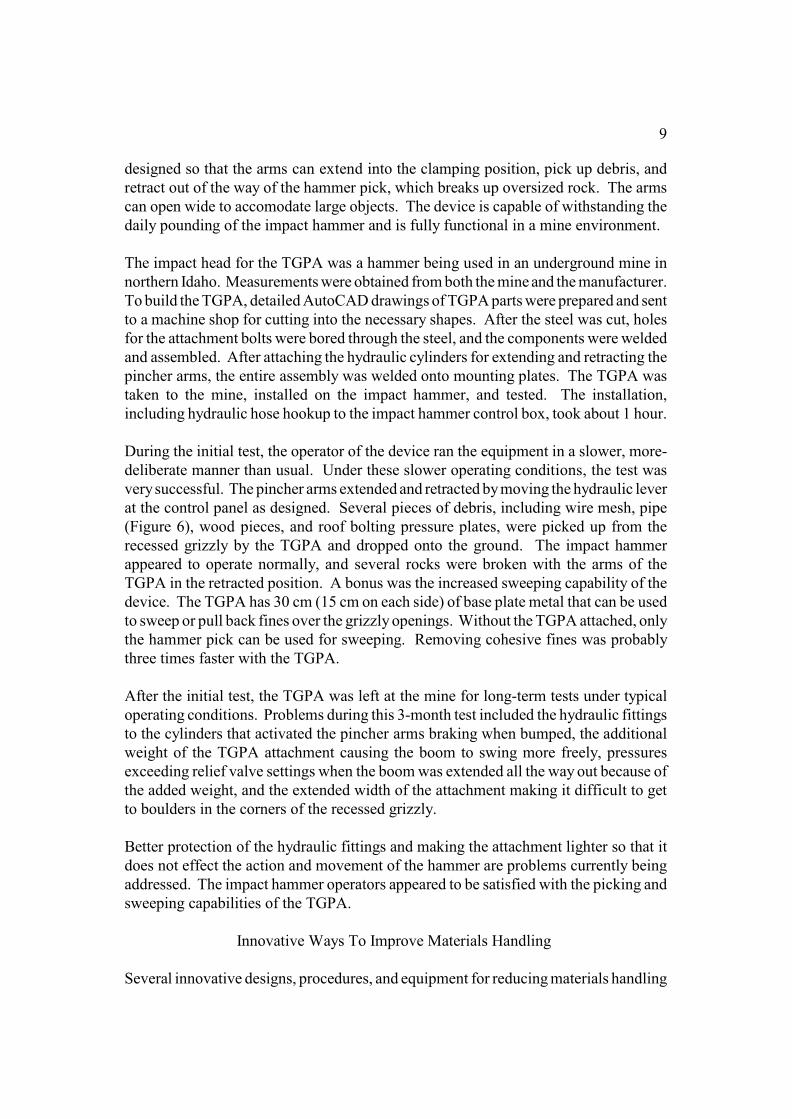
designed so that the arms can extend into the clamping position, pick up debris, andretract out of the way of the hammer pick, which breaks up oversized rock. The armscan open wide to accomodate large objects. The device is capable of withstanding thedaily pounding of the impact hammer and is fully functional in a mine environment.
The impact head for the TGPA was a hammer being used in an underground mine innorthern Idaho. Measurements were obtained from both the mine and the manufacturer.To build the TGPA, detailed AutoCAD drawings of TGPA parts were prepared and sentto a machine shop for cutting into the necessary shapes. After the steel was cut, holesfor the attachment bolts were bored through the steel, and the components were weldedand assembled. After attaching the hydraulic cylinders for extending and retracting thepincher arms, the entire assembly was welded onto mounting plates. The TGPA wastaken to the mine, installed on the impact hammer, and tested. The installation,including hydraulic hose hookup to the impact hammer control box, took about 1 hour.
During the initial test, the operator of the device ran the equipment in a slower, more-deliberate manner than usual. Under these slower operating conditions, the test wasvery successful. The pincher arms extended and retracted by moving the hydraulic leverat the control panel as designed. Several pieces of debris, including wire mesh, pipe(Figure 6), wood pieces, and roof bolting pressure plates, were picked up from therecessed grizzly by the TGPA and dropped onto the ground. The impact hammerappeared to operate normally, and several rocks were broken with the arms of theTGPA in the retracted position. A bonus was the increased sweeping capability of thedevice. The TGPA has 30 cm (15 cm on each side) of base plate metal that can be usedto sweep or pull back fines over the grizzly openings. Without the TGPA attached, onlythe hammer pick can be used for sweeping. Removing cohesive fines was probablythree times faster with the TGPA.
After the initial test, the TGPA was left at the mine for long-term tests under typicaloperating conditions. Problems during this 3-month test included the hydraulic fittingsto the cylinders that activated the pincher arms braking when bumped, the additionalweight of the TGPA attachment causing the boom to swing more freely, pressuresexceeding relief valve settings when the boom was extended all the way out because ofthe added weight, and the extended width of the attachment making it difficult to getto boulders in the corners of the recessed grizzly.
Better protection of the hydraulic fittings and making the attachment lighter so that itdoes not effect the action and movement of the hammer are problems currently beingaddressed. The impact hammer operators appeared to be satisfied with the picking andsweeping capabilities of the TGPA.
Innovative Ways To Improve Materials Handling
Several innovative designs, procedures, and equipment for reducing materials handling
10
injuries were observed during mine visits. Many of these involved the use ofmechanized equipment to aid in lifting.
Can Cribs
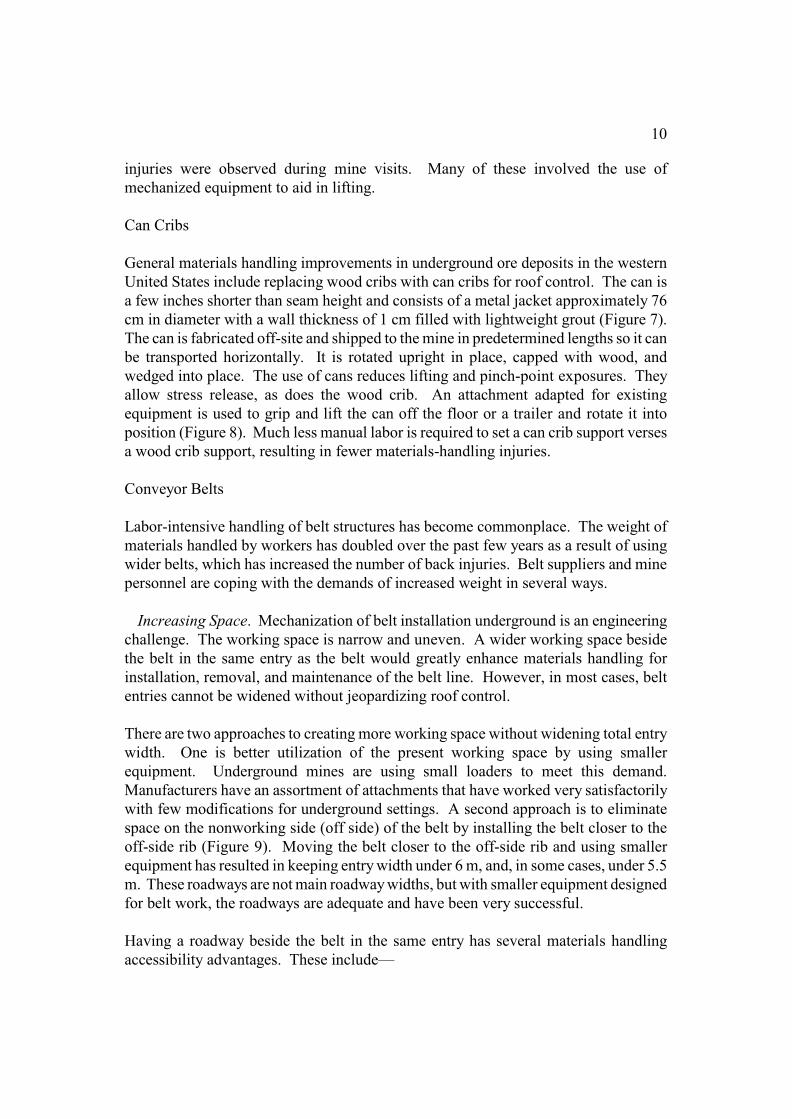
General materials handling improvements in underground ore deposits in the westernUnited States include replacing wood cribs with can cribs for roof control. The can isa few inches shorter than seam height and consists of a metal jacket approximately 76cm in diameter with a wall thickness of 1 cm filled with lightweight grout (Figure 7).The can is fabricated off-site and shipped to the mine in predetermined lengths so it canbe transported horizontally. It is rotated upright in place, capped with wood, andwedged into place. The use of cans reduces lifting and pinch-point exposures. Theyallow stress release, as does the wood crib. An attachment adapted for existingequipment is used to grip and lift the can off the floor or a trailer and rotate it intoposition (Figure 8). Much less manual labor is required to set a can crib support versesa wood crib support, resulting in fewer materials-handling injuries.
Conveyor Belts
Labor-intensive handling of belt structures has become commonplace. The weight ofmaterials handled by workers has doubled over the past few years as a result of usingwider belts, which has increased the number of back injuries. Belt suppliers and minepersonnel are coping with the demands of increased weight in several ways.
Increasing Space. Mechanization of belt installation underground is an engineeringchallenge. The working space is narrow and uneven. A wider working space besidethe belt in the same entry as the belt would greatly enhance materials handling forinstallation, removal, and maintenance of the belt line. However, in most cases, beltentries cannot be widened without jeopardizing roof control.
There are two approaches to creating more working space without widening total entrywidth. One is better utilization of the present working space by using smallerequipment. Underground mines are using small loaders to meet this demand.Manufacturers have an assortment of attachments that have worked very satisfactorilywith few modifications for underground settings. A second approach is to eliminatespace on the nonworking side (off side) of the belt by installing the belt closer to theoff-side rib (Figure 9). Moving the belt closer to the off-side rib and using smallerequipment has resulted in keeping entry width under 6 m, and, in some cases, under 5.5m. These roadways are not main roadway widths, but with smaller equipment designedfor belt work, the roadways are adequate and have been very successful.
Having a roadway beside the belt in the same entry has several materials handlingaccessibility advantages. These include—
11
• Allowing a piece of equipment to be available for lifting materials during installation.• Eliminating the need to carry materials between crosscuts during maintenance.• Allowing better inspection of the belt for maintenance and during a belt shutdown.• Allowing better access for cleaning underneath the belt with mechanized equipment.• Allowing more thorough rock dusting.
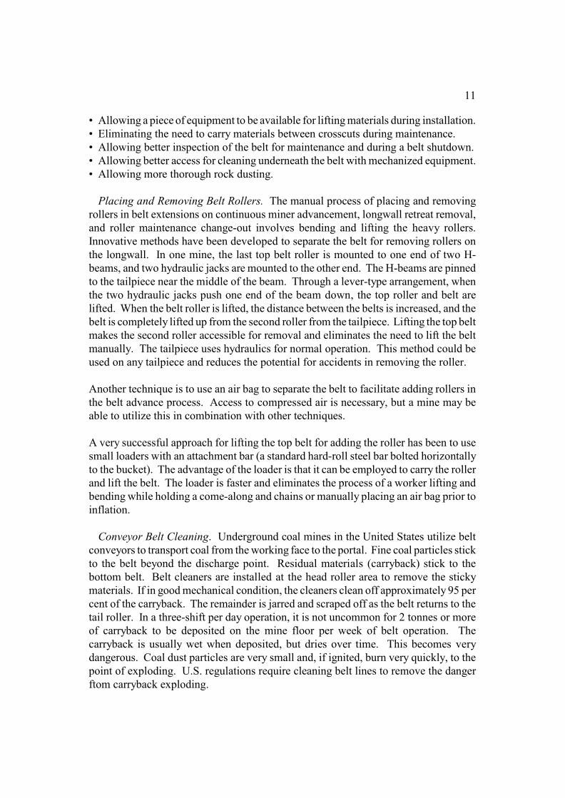
Placing and Removing Belt Rollers. The manual process of placing and removingrollers in belt extensions on continuous miner advancement, longwall retreat removal,and roller maintenance change-out involves bending and lifting the heavy rollers.Innovative methods have been developed to separate the belt for removing rollers onthe longwall. In one mine, the last top belt roller is mounted to one end of two H-beams, and two hydraulic jacks are mounted to the other end. The H-beams are pinnedto the tailpiece near the middle of the beam. Through a lever-type arrangement, whenthe two hydraulic jacks push one end of the beam down, the top roller and belt arelifted. When the belt roller is lifted, the distance between the belts is increased, and thebelt is completely lifted up from the second roller from the tailpiece. Lifting the top beltmakes the second roller accessible for removal and eliminates the need to lift the beltmanually. The tailpiece uses hydraulics for normal operation. This method could beused on any tailpiece and reduces the potential for accidents in removing the roller.
Another technique is to use an air bag to separate the belt to facilitate adding rollers inthe belt advance process. Access to compressed air is necessary, but a mine may beable to utilize this in combination with other techniques.
A very successful approach for lifting the top belt for adding the roller has been to usesmall loaders with an attachment bar (a standard hard-roll steel bar bolted horizontallyto the bucket). The advantage of the loader is that it can be employed to carry the rollerand lift the belt. The loader is faster and eliminates the process of a worker lifting andbending while holding a come-along and chains or manually placing an air bag prior toinflation.
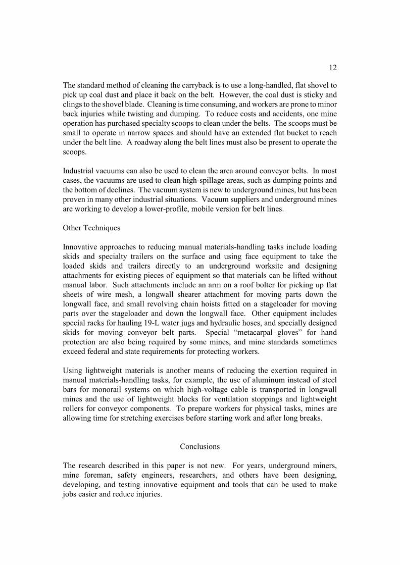
Conveyor Belt Cleaning. Underground coal mines in the United States utilize beltconveyors to transport coal from the working face to the portal. Fine coal particles stickto the belt beyond the discharge point. Residual materials (carryback) stick to thebottom belt. Belt cleaners are installed at the head roller area to remove the stickymaterials. If in good mechanical condition, the cleaners clean off approximately 95 percent of the carryback. The remainder is jarred and scraped off as the belt returns to thetail roller. In a three-shift per day operation, it is not uncommon for 2 tonnes or moreof carryback to be deposited on the mine floor per week of belt operation. Thecarryback is usually wet when deposited, but dries over time. This becomes verydangerous. Coal dust particles are very small and, if ignited, burn very quickly, to thepoint of exploding. U.S. regulations require cleaning belt lines to remove the dangerftom carryback exploding.
12
The standard method of cleaning the carryback is to use a long-handled, flat shovel topick up coal dust and place it back on the belt. However, the coal dust is sticky andclings to the shovel blade. Cleaning is time consuming, and workers are prone to minorback injuries while twisting and dumping. To reduce costs and accidents, one mineoperation has purchased specialty scoops to clean under the belts. The scoops must besmall to operate in narrow spaces and should have an extended flat bucket to reachunder the belt line. A roadway along the belt lines must also be present to operate thescoops.
Industrial vacuums can also be used to clean the area around conveyor belts. In mostcases, the vacuums are used to clean high-spillage areas, such as dumping points andthe bottom of declines. The vacuum system is new to underground mines, but has beenproven in many other industrial situations. Vacuum suppliers and underground minesare working to develop a lower-profile, mobile version for belt lines.
Other Techniques
Innovative approaches to reducing manual materials-handling tasks include loadingskids and specialty trailers on the surface and using face equipment to take theloaded skids and trailers directly to an underground worksite and designingattachments for existing pieces of equipment so that materials can be lifted withoutmanual labor. Such attachments include an arm on a roof bolter for picking up flatsheets of wire mesh, a longwall shearer attachment for moving parts down thelongwall face, and small revolving chain hoists fitted on a stageloader for movingparts over the stageloader and down the longwall face. Other equipment includesspecial racks for hauling 19-L water jugs and hydraulic hoses, and specially designedskids for moving conveyor belt parts. Special “metacarpal gloves” for handprotection are also being required by some mines, and mine standards sometimesexceed federal and state requirements for protecting workers.
Using lightweight materials is another means of reducing the exertion required inmanual materials-handling tasks, for example, the use of aluminum instead of steelbars for monorail systems on which high-voltage cable is transported in longwallmines and the use of lightweight blocks for ventilation stoppings and lightweightrollers for conveyor components. To prepare workers for physical tasks, mines areallowing time for stretching exercises before starting work and after long breaks.
Conclusions
The research described in this paper is not new. For years, underground miners,mine foreman, safety engineers, researchers, and others have been designing,developing, and testing innovative equipment and tools that can be used to makejobs easier and reduce injuries.
13
Yet, in spite of the ingenuity of many people and the development of manymechanized aids, materials handling continues to be the MSHA category with thehighest percentage of accidents and injuries in underground mines. Hundreds ofmaterials-handling tasks are performed in underground mines each day. It would behard to find one of these tasks that has not resulted in an injury at least once.
Some solutions are simple, such as reducing “package” weight. Other solutions arenot so simple, such as hanging objects overhead and moving trailing cables.Because of the diversity of materials-handling tasks, no single solution exists toeliminate materials-handling injuries. It is neither technically or economicallyfeasible to mechanize all underground materials-handling tasks. Some tasks need tobe done manually. The individual performing any materials-handling task, no matterhow large or small, must take special precautions and get into the habit of thinkingabout the lift prior to doing it. No one likes to get hurt, and there is always a better,less strenuous way to lift a heavy object.
Research and development of materials-handling tools and equipment need tocontinue with an emphasis on those tasks that result in numerous materials-handlinginjuries, such as moving roof bolt supplies, hanging waterlines and ventilation tubes,and moving cables. One approach is to have mine safety officers identify those tasksthat cause frequent injuries at a given mine and conduct specialized materials-handling safety training to individuals performing these tasks. This would bevaluable for new miners because they frequently get jobs involving supplies andmaterials. Constant (daily) safe materials-handling reminders from safety managersand shift foremen will aid in getting miners into the habit of not only “thinkingbefore they lift,” but also thinking before they carry, pull, hang, or push supplies andmaterials.
Acknowledgments
The authors would like to thank Mr. Harvey Keim, Mr. Jim Taylor, and Mr. ClydePeppin, Hecla Mining Company-Lucky Friday Unit, for their cooperation during thetests of the track-guided pincher arm. Not only did they allow us to use one of theiractive impact hammers for the tests, but they helped install the device, hooked up thehydraulics hoses, operated the hammer controls during the initial 60-min short-termtest, and gave us feedback on the long-term tests.
The authors would also like to thank Mr. W.R. Gaston, Olin Corp.-WinchesterDivision, for giving us free use of the industrial gun and ammunition used during therock-breaking tests.
The authors would like to thank all the mining companies and mine personnel forthe tours of materials-handling activities and the time they spent discussing theirmaterials-handling activities:
14
Finally, the authors would like to thank Ken Strunk for his graphics expertise andPriscilla Wopat for her editorial expertise in completing this paper.
References
1. Bureau of Mines. Back Injuries. Proceedings: Bureau of Mines TechnologyTransfer Symposium (Pittsburgh, PA, Aug. 9,1983; Reno, NV, Aug.15, 1983),J.M. Peay (comp.). Bureau of Mines Information Circular 8948, 1983, 110 pp.
2. Gallagher, S., Bobick, T.G., and Unger, R.L. Reducing back injuries in low-coal mines: Redesign of materials-handling tasks. U.S. Bureau of MinesInformation Circular 9235, 1990, 33 pp.
3. Mine Safety and Health Administration, Denver, CO. Quarterly employmentand coal production accidents/injuries/illnesses reported to MSHA under 30CFR Part 50, 1986-1997. 1999.
4. National Institute for Occupational Safety and Health. Ch. 6. Worker HealthChart Book, 2000. Publi. No. 2000-127, Sept. 2000, 29 pp.
5. Stobbe, T.J., Plummer, R.W., and Jaraiedi, M. Back injuries in undergroundcoal mines: Final report. U.S. Bureau of Mines research contract J0 348044-05.West Virginia University. 1989.
6. Conway, E.J., and Unger, R.L. Materials handling devices for undergroundmines. U.S. Bureau of Mines Information Circular 9212, 1989, 48 pp.
7. Unger, R.L., and Bobick, T.G. Bureau of Mines research into reducingmaterials-handling injuries. Bureau of Mines Information Circular 9097, 1986,22 pp.
List of Figures
Figure 1.–Materials-handling back injuries from 20 underground mines, 1999.
Figure 2.– Laboratory tests on Coleman manipulator as received from factory.
Figure 3.– Artist’s concept of mobile manipulator after modifications.
Figure 4.– Shield and industrial gun. (A) Setup for rock-breaking tests; (B) gun suspended
from roof of shield.
Figure 5.– Track-guided pincher arm attached to hydraulic impact hammer head.
Figure 6.– Track-guided pincher arm picking up pipe debris from recessed grizzly.
Figure 7.– Can crib used to replace wood crib in underground coal mines.
Figure 8.– Attachment used to pick up and maneuver can cribs.
Figure 9.–Layout for belt entry to accommodate materials-handling equipment.
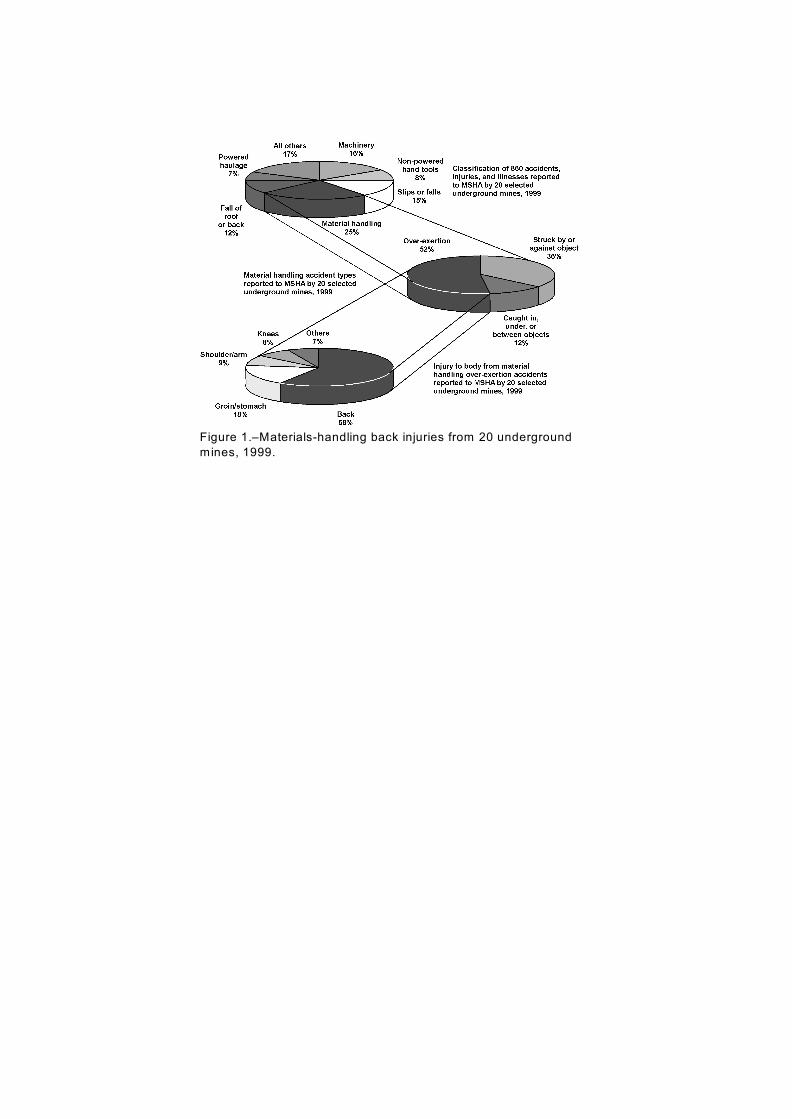
Figure 1.–Materials-handling back injuries from 20 underground
mines, 1999.
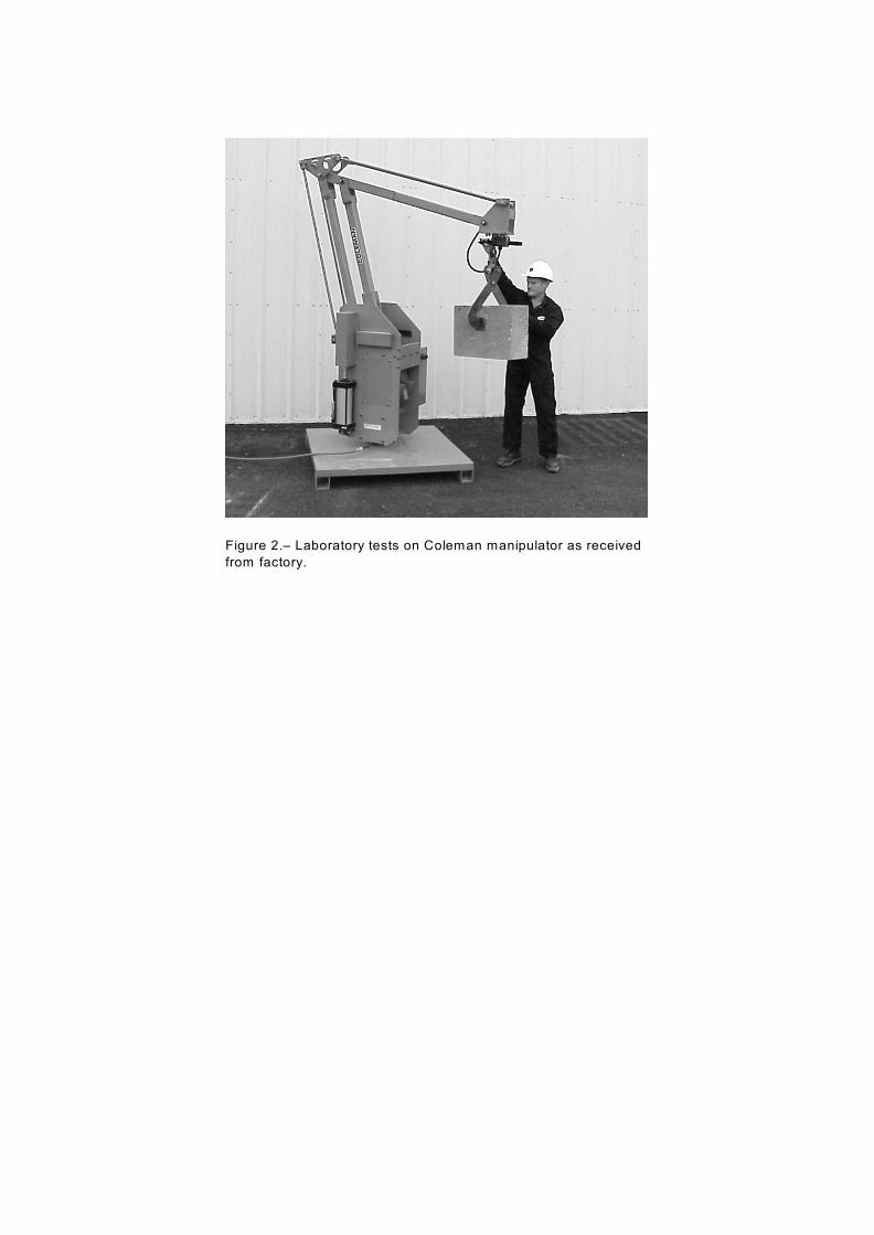
Figure 2.– Laboratory tests on Coleman manipulator as received
from factory.
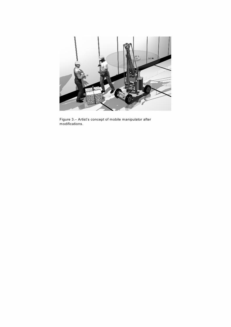
Figure 3.– Artist’s concept of mobile manipulator after
modifications.
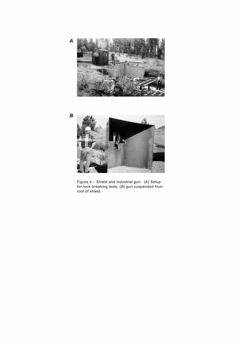
Figure 4.– Shield and industrial gun. (A) Setup
for rock-breaking tests; (B) gun suspended from
roof of shield.
A
B
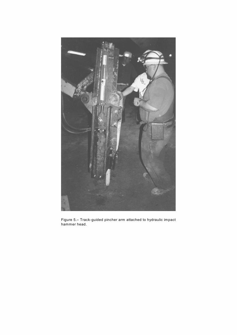
Figure 5.– Track-guided pincher arm attached to hydraulic impact
hammer head.
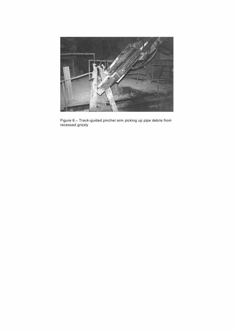
Figure 6.– Track-guided pincher arm picking up pipe debris from
recessed grizzly
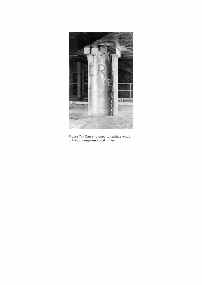
Figure 7.– Can crib used to replace wood
crib in underground coal mines.
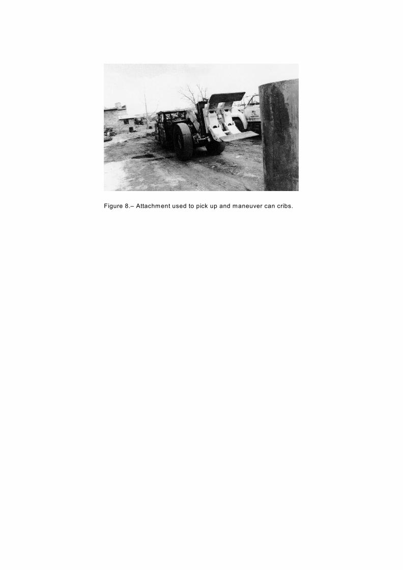
Figure 8.– Attachment used to pick up and maneuver can cribs.
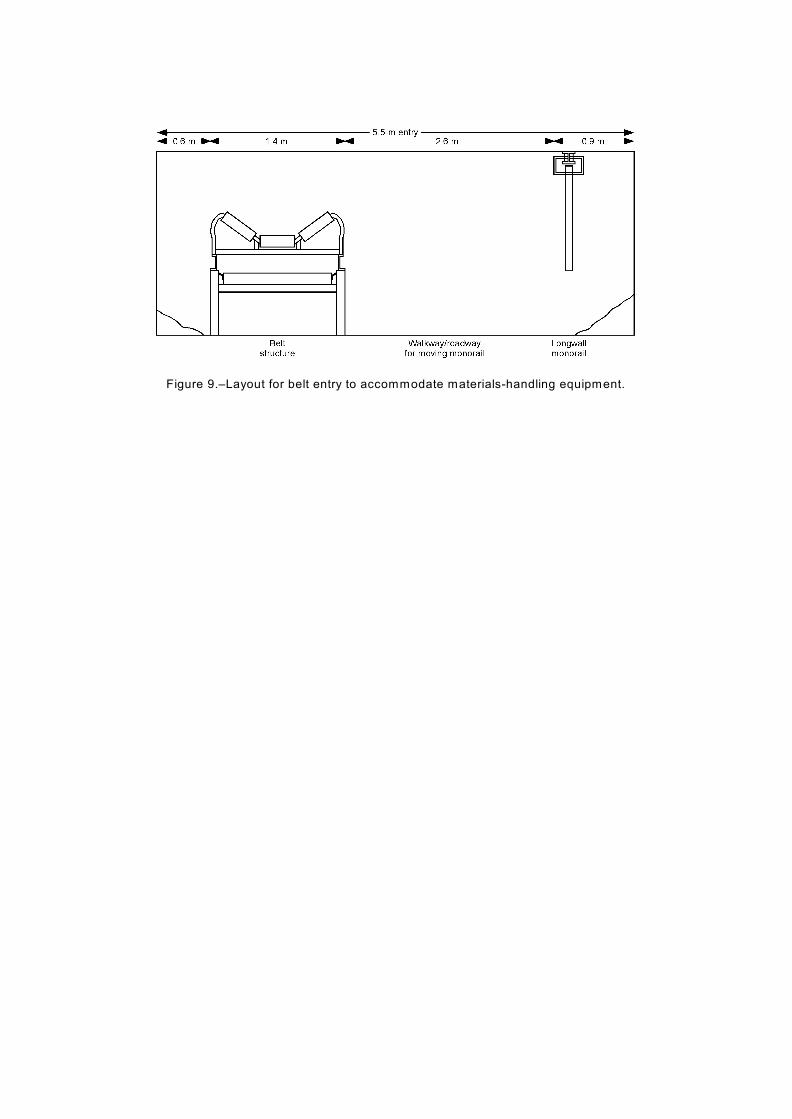
Figure 9.–Layout for belt entry to accommodate materials-handling equipment.