Embed Size (px)
Citation preview
Materials for
PEM Fuel Cells
Alberto García TECNALIA
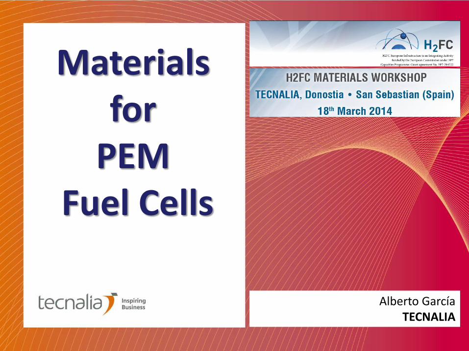
Proton Exchange Membrane Fuel cells
Polymeric Fuel Cells PEMFC
Hydrogen Oxidation Reaction (HOR):
Oxygen reduction reaction (ORR):
Overall reaction:
1,23 V
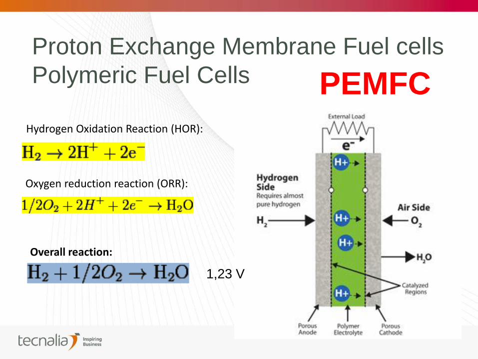
MEA
(Membrane electrode Assembly)
COMPONENTS OF A PEM SINGLE CELL
GDL GDL
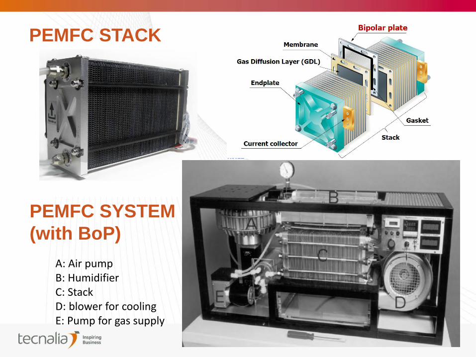
PEMFC STACK
PEMFC SYSTEM
(with BoP)
A: Air pump B: Humidifier C: Stack D: blower for cooling E: Pump for gas supply
1. REDUCTION OF COSTS
2. INCREASED PERFORMANCE
3. LONGER DURABILITY
THE GOAL OF MATERIALS OPTIMIZATION IN PEMFC
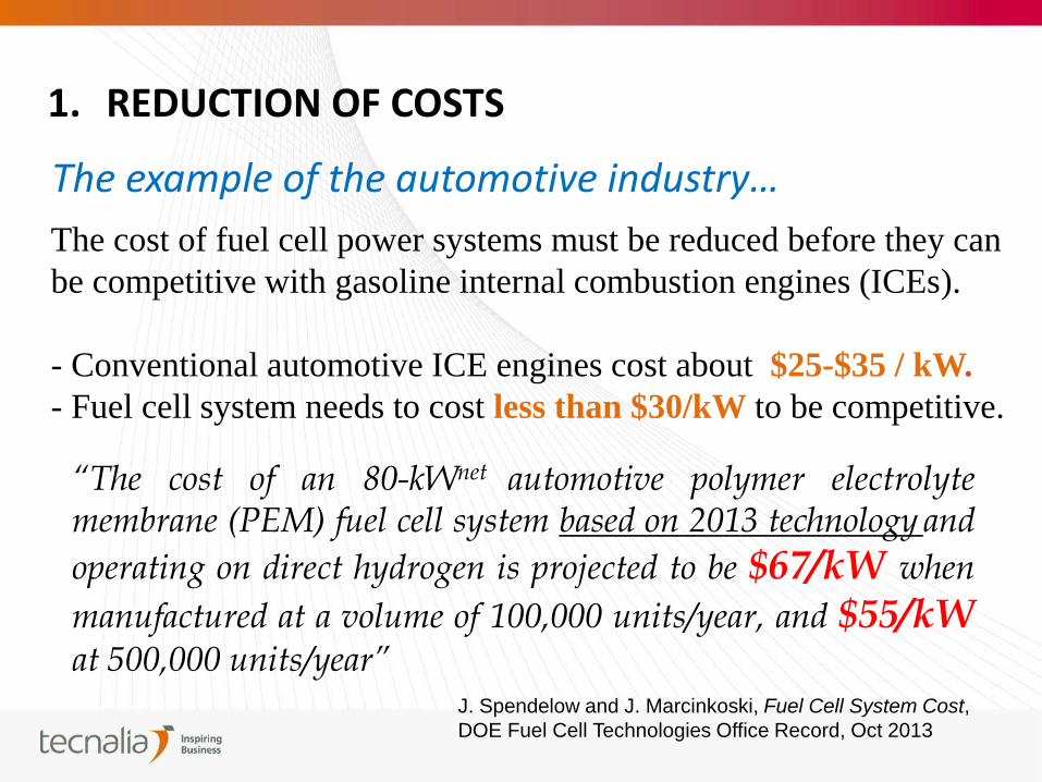
1. REDUCTION OF COSTS
The example of the automotive industry…
The cost of fuel cell power systems must be reduced before they can
be competitive with gasoline internal combustion engines (ICEs).
- Conventional automotive ICE engines cost about $25-$35 / kW.
- Fuel cell system needs to cost less than $30/kW to be competitive.
“The cost of an 80-kWnet automotive polymer electrolyte membrane (PEM) fuel cell system based on 2013 technology and
operating on direct hydrogen is projected to be $67/kW when
manufactured at a volume of 100,000 units/year, and $55/kW at 500,000 units/year”
J. Spendelow and J. Marcinkoski, Fuel Cell System Cost,
DOE Fuel Cell Technologies Office Record, Oct 2013
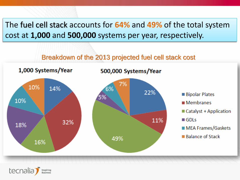
Breakdown of the 2013 projected fuel cell stack cost
The fuel cell stack accounts for 64% and 49% of the total system cost at 1,000 and 500,000 systems per year, respectively.
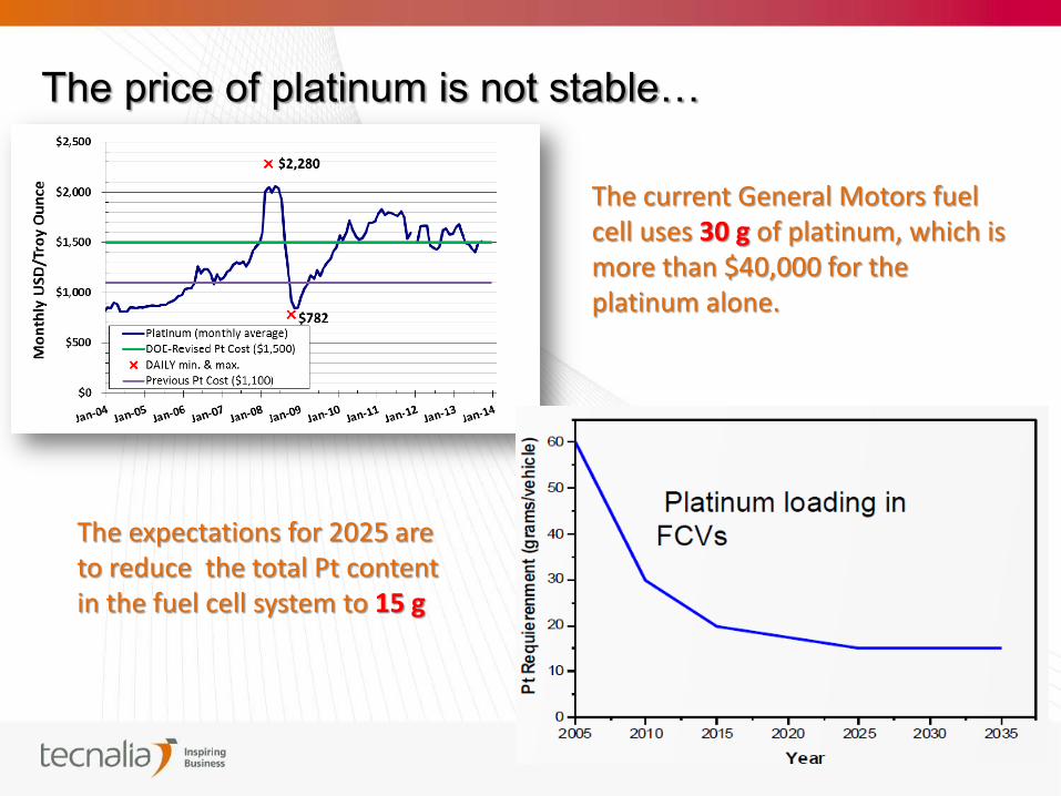
The current General Motors fuel cell uses 30 g of platinum, which is more than $40,000 for the platinum alone.
The price of platinum is not stable…
The expectations for 2025 are to reduce the total Pt content in the fuel cell system to 15 g
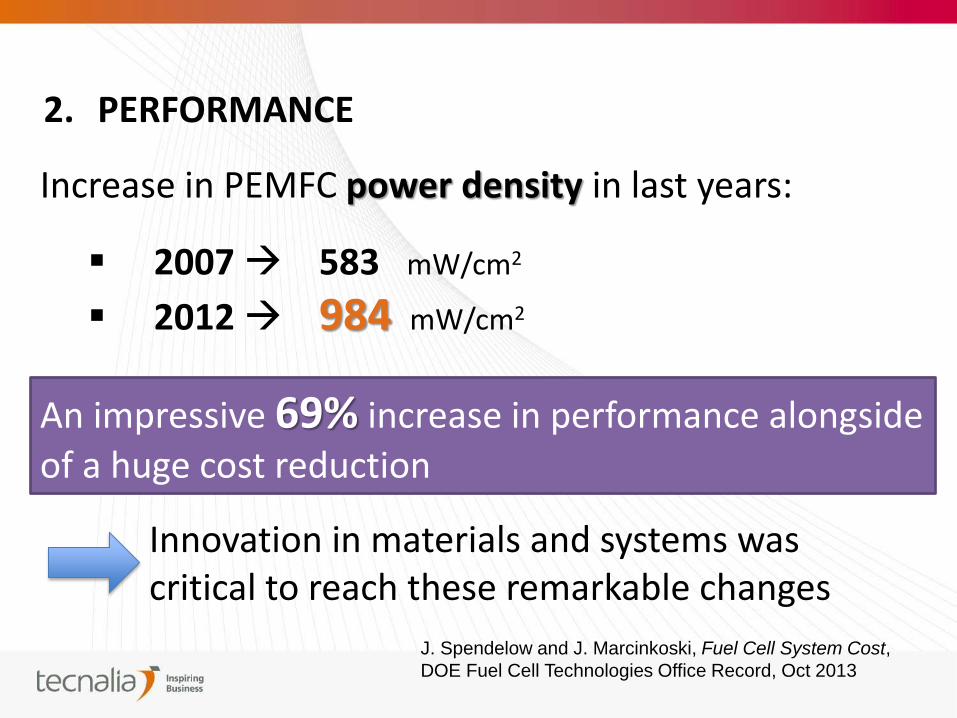
2. PERFORMANCE
Increase in PEMFC power density in last years:
2007 583 mW/cm2
2012 984 mW/cm2
An impressive 69% increase in performance alongside
of a huge cost reduction
Innovation in materials and systems was critical to reach these remarkable changes
J. Spendelow and J. Marcinkoski, Fuel Cell System Cost,
DOE Fuel Cell Technologies Office Record, Oct 2013
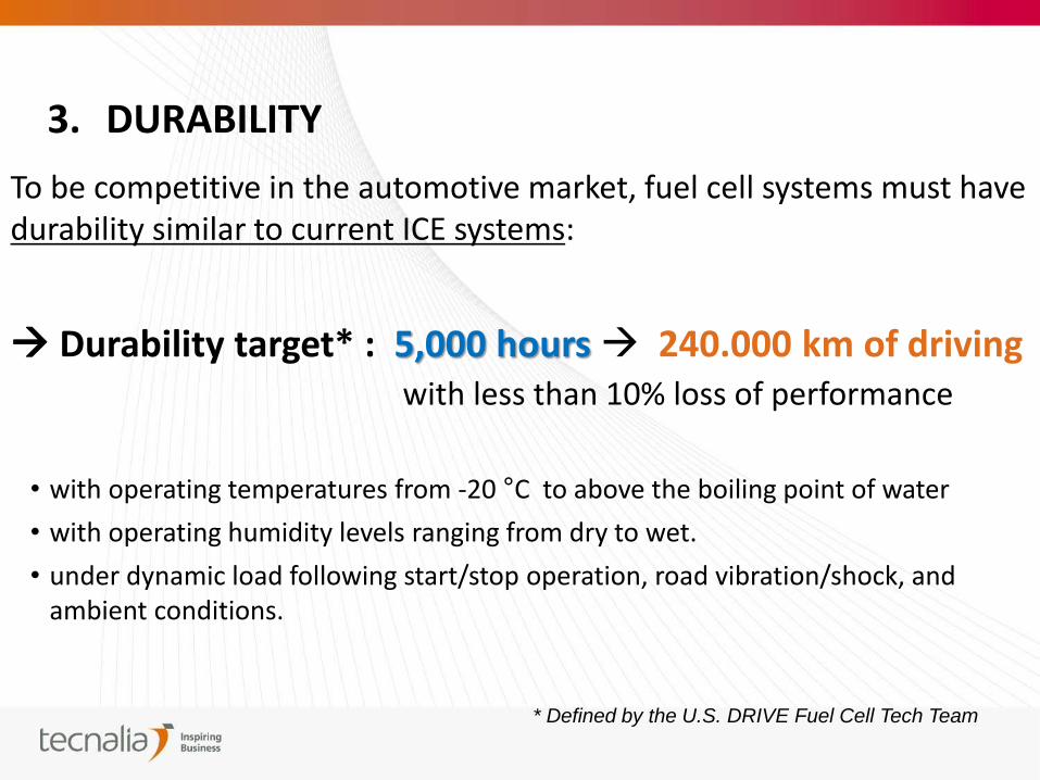
3. DURABILITY
To be competitive in the automotive market, fuel cell systems must have durability similar to current ICE systems:
Durability target* : 5,000 hours 240.000 km of driving with less than 10% loss of performance
• with operating temperatures from -20 °C to above the boiling point of water
• with operating humidity levels ranging from dry to wet.
• under dynamic load following start/stop operation, road vibration/shock, and ambient conditions.
* Defined by the U.S. DRIVE Fuel Cell Tech Team
Durability and cost are both related to catalyst loading (optimization of amount of Pt and particle size):
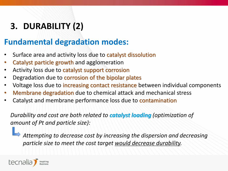
3. DURABILITY (2)
Fundamental degradation modes:
• Surface area and activity loss due to catalyst dissolution • Catalyst particle growth and agglomeration • Activity loss due to catalyst support corrosion • Degradation due to corrosion of the bipolar plates • Voltage loss due to increasing contact resistance between individual components • Membrane degradation due to chemical attack and mechanical stress • Catalyst and membrane performance loss due to contamination
Attempting to decrease cost by increasing the dispersion and decreasing particle size to meet the cost target would decrease durability.
MATERIALS
FOR PEMFC
ELECTRODES
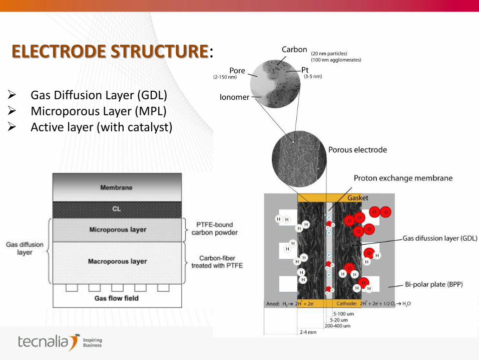
ELECTRODE STRUCTURE: Gas Diffusion Layer (GDL) Microporous Layer (MPL) Active layer (with catalyst)
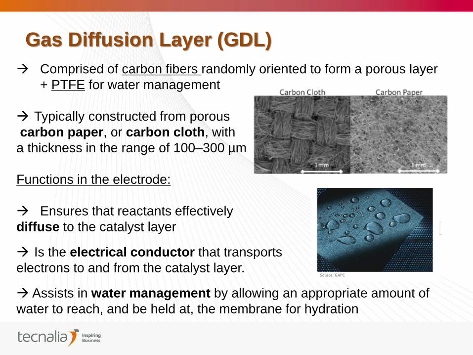
Comprised of carbon fibers randomly oriented to form a porous layer
+ PTFE for water management
Typically constructed from porous
carbon paper, or carbon cloth, with
a thickness in the range of 100–300 µm
Functions in the electrode:
Ensures that reactants effectively
diffuse to the catalyst layer
Is the electrical conductor that transports
electrons to and from the catalyst layer.
Assists in water management by allowing an appropriate amount of
water to reach, and be held at, the membrane for hydration
Gas Diffusion Layer (GDL)
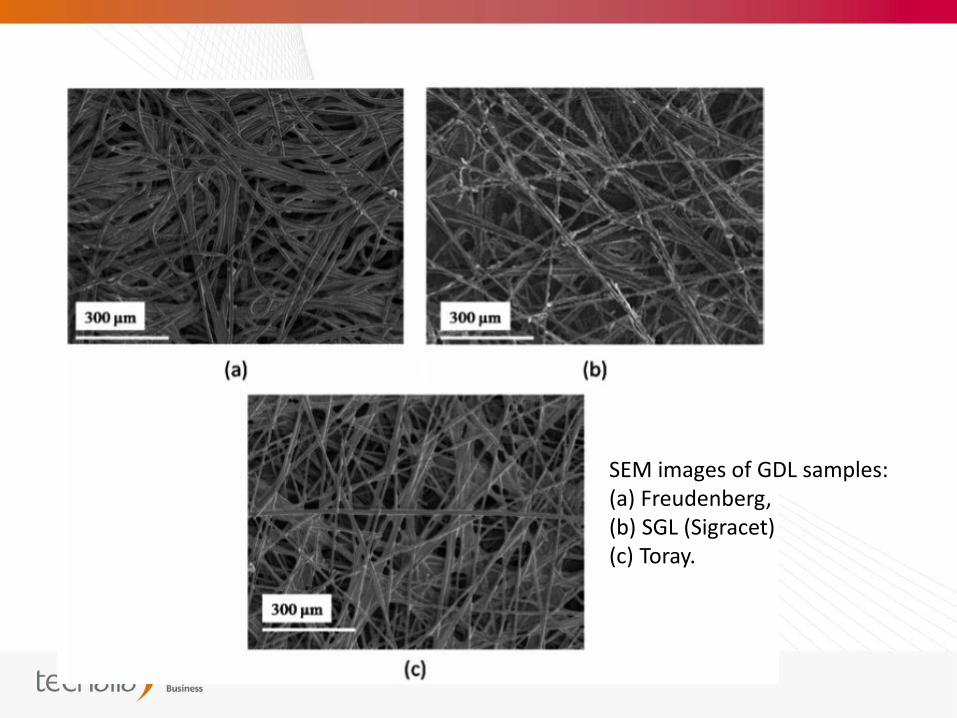
SEM images of GDL samples: (a) Freudenberg, (b) SGL (Sigracet) (c) Toray.
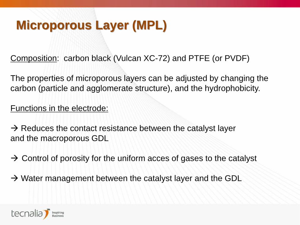
Composition: carbon black (Vulcan XC-72) and PTFE (or PVDF)
The properties of microporous layers can be adjusted by changing the
carbon (particle and agglomerate structure), and the hydrophobicity.
Functions in the electrode:
Reduces the contact resistance between the catalyst layer
and the macroporous GDL
Control of porosity for the uniform acces of gases to the catalyst
Water management between the catalyst layer and the GDL
Microporous Layer (MPL)
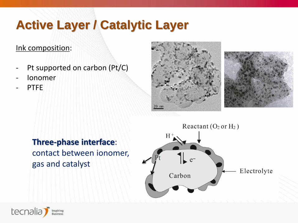
Ink composition: - Pt supported on carbon (Pt/C) - Ionomer - PTFE
Active Layer / Catalytic Layer
Pt
Three-phase interface: contact between ionomer, gas and catalyst
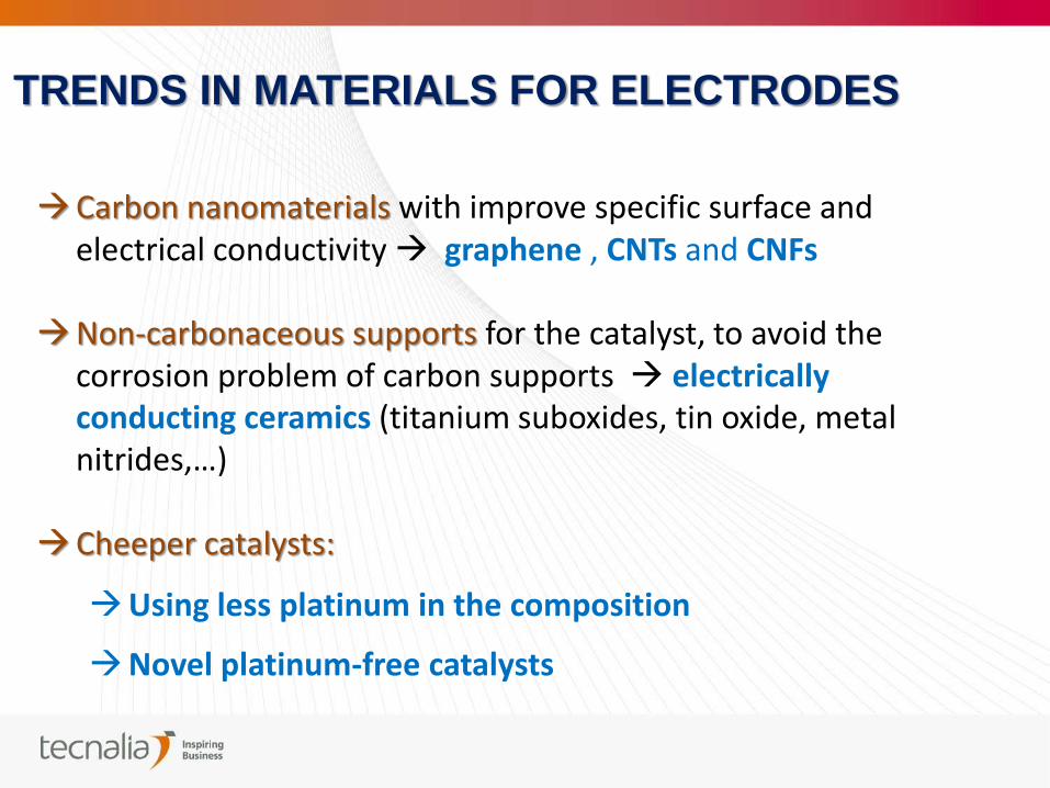
Carbon nanomaterials with improve specific surface and electrical conductivity graphene , CNTs and CNFs
Non-carbonaceous supports for the catalyst, to avoid the corrosion problem of carbon supports electrically conducting ceramics (titanium suboxides, tin oxide, metal nitrides,…)
Cheeper catalysts:
Using less platinum in the composition
Novel platinum-free catalysts
TRENDS IN MATERIALS FOR ELECTRODES
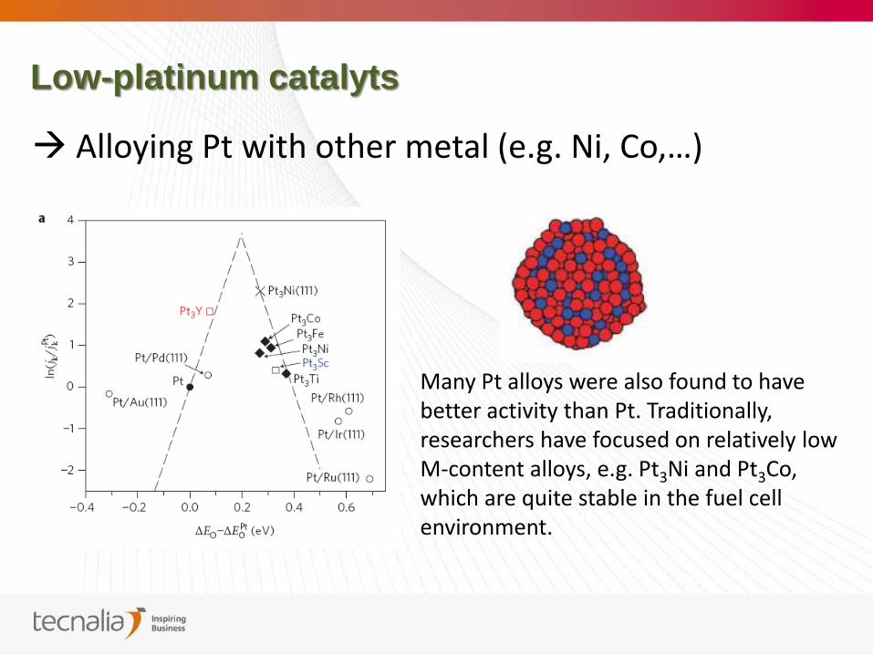
Low-platinum catalyts
Alloying Pt with other metal (e.g. Ni, Co,…)
Many Pt alloys were also found to have better activity than Pt. Traditionally, researchers have focused on relatively low M-content alloys, e.g. Pt3Ni and Pt3Co, which are quite stable in the fuel cell environment.
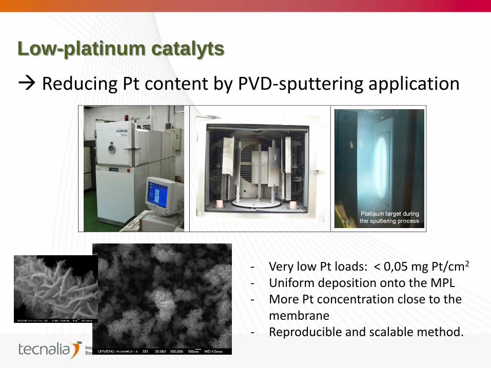
Low-platinum catalyts
Reducing Pt content by PVD-sputtering application
- Very low Pt loads: < 0,05 mg Pt/cm2 - Uniform deposition onto the MPL - More Pt concentration close to the
membrane - Reproducible and scalable method.
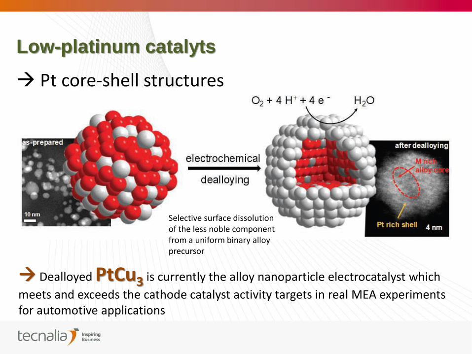
Low-platinum catalyts
Pt core-shell structures
Selective surface dissolution of the less noble component from a uniform binary alloy precursor
Dealloyed PtCu3 is currently the alloy nanoparticle electrocatalyst which
meets and exceeds the cathode catalyst activity targets in real MEA experiments for automotive applications
Platinum-free catalyts:
New‐generation chalcogenides (Ru‐Mo sulfide, selenides)
Non‐precious metal/heteroatomic polymer nanocomposites
Bio-inspired catalysts: Fe or Co-N4 macrocyclic compounds (e.g. Fe/Co porphyrins, phthalocyanines)
Even if the potential of the catalytic activity of this novel family of products has been shown in half cell
measurement, the current densities obtained still suffer to be around several orders of magnitude
lower than the classical Pt catalyst. Also, durability must be demonstrated for these new catalyts.
OPEN FIELD FOR MATERIALS RESEARCH
MATERIALS
FOR PEMFC
BIPOLAR PLATES
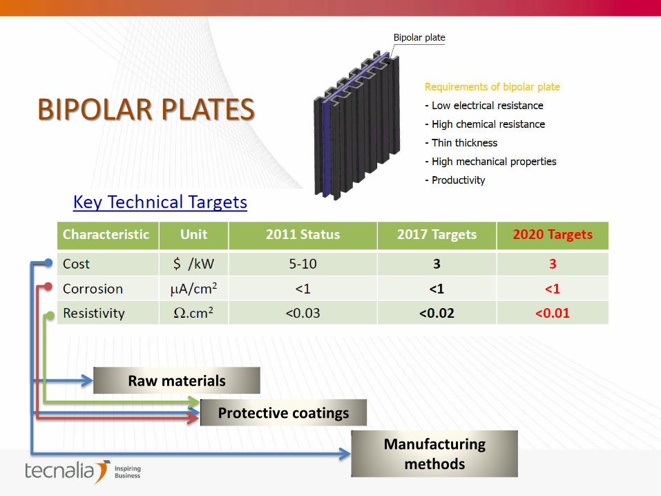
Manufacturing methods
Raw materials
Protective coatings
BIPOLAR PLATES
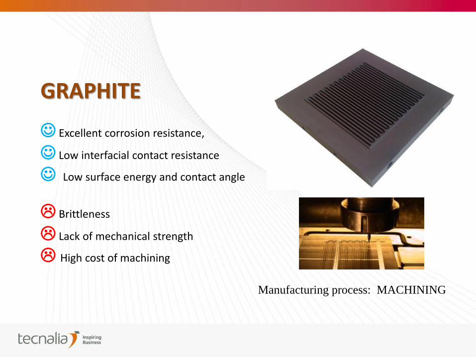
GRAPHITE
Excellent corrosion resistance,
Low interfacial contact resistance
Low surface energy and contact angle
Brittleness
Lack of mechanical strength
High cost of machining
Manufacturing process: MACHINING
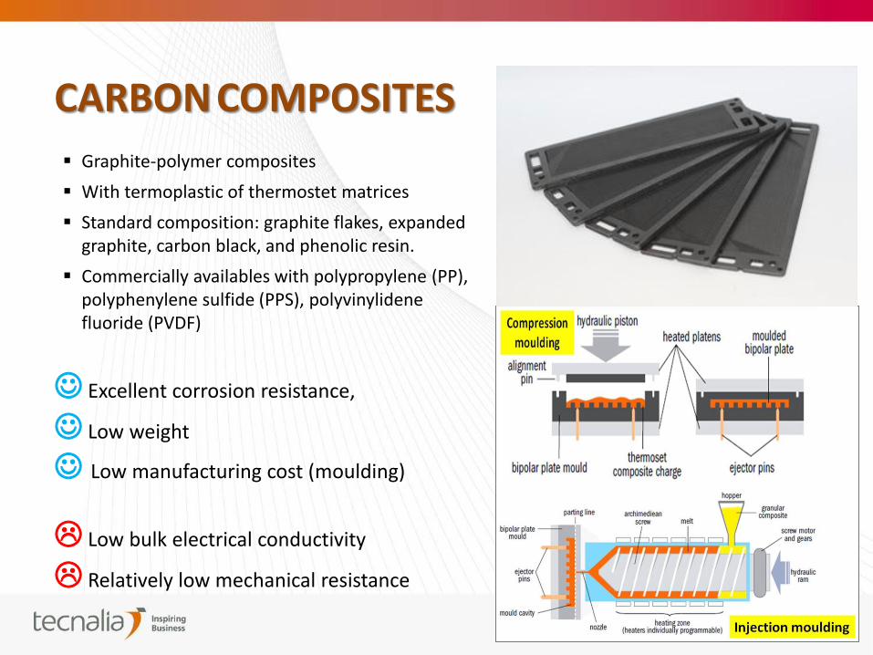
CARBON COMPOSITES Graphite-polymer composites
With termoplastic of thermostet matrices
Standard composition: graphite flakes, expanded graphite, carbon black, and phenolic resin.
Commercially availables with polypropylene (PP), polyphenylene sulfide (PPS), polyvinylidene fluoride (PVDF)
Excellent corrosion resistance,
Low weight
Low manufacturing cost (moulding)
Low bulk electrical conductivity
Relatively low mechanical resistance
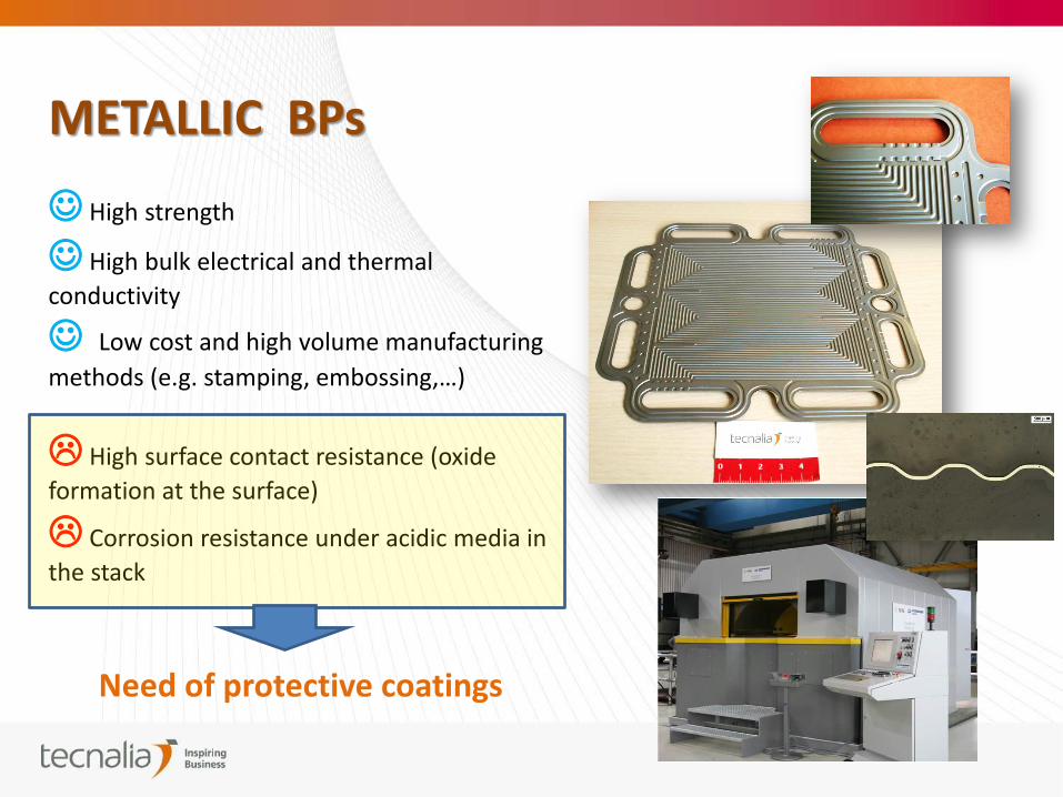
METALLIC BPs
High strength
High bulk electrical and thermal
conductivity
Low cost and high volume manufacturing
methods (e.g. stamping, embossing,…)
High surface contact resistance (oxide
formation at the surface)
Corrosion resistance under acidic media in
the stack
Need of protective coatings
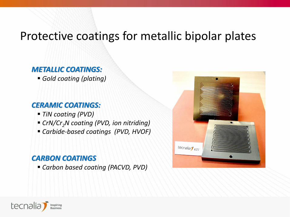
Protective coatings for metallic bipolar plates
METALLIC COATINGS: Gold coating (plating)
CERAMIC COATINGS: TiN coating (PVD) CrN/Cr2N coating (PVD, ion nitriding) Carbide-based coatings (PVD, HVOF)
CARBON COATINGS Carbon based coating (PACVD, PVD)
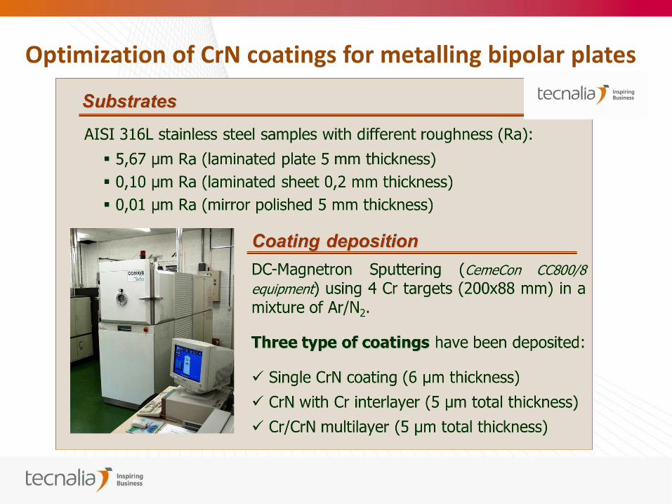
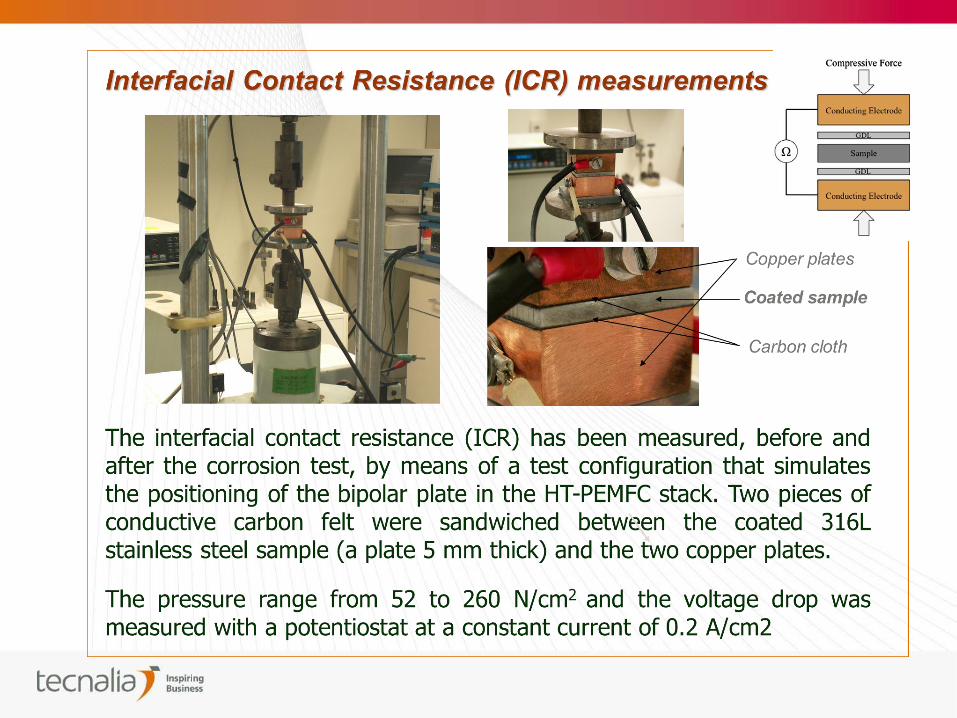
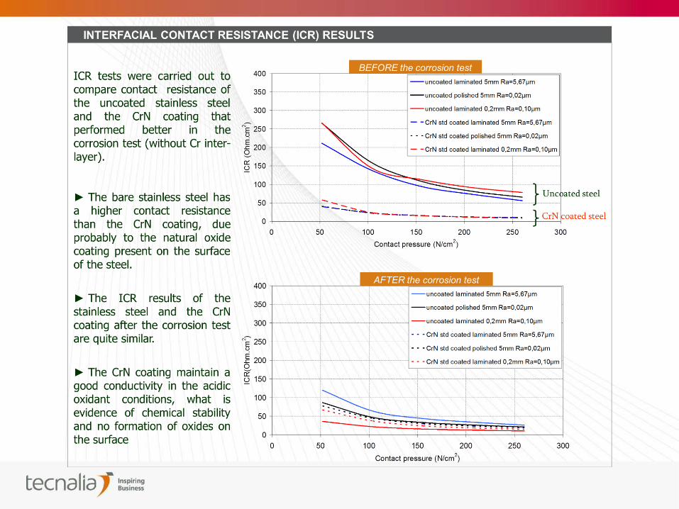
Optimization of CrN coatings for metalling bipolar plates
MATERIALS
FOR PEMFC
MEMBRANES
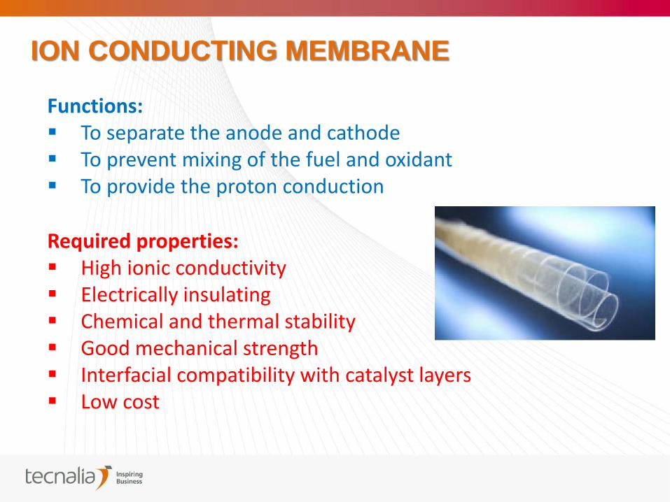
Functions: To separate the anode and cathode To prevent mixing of the fuel and oxidant To provide the proton conduction
Required properties: High ionic conductivity Electrically insulating Chemical and thermal stability Good mechanical strength Interfacial compatibility with catalyst layers Low cost
ION CONDUCTING MEMBRANE
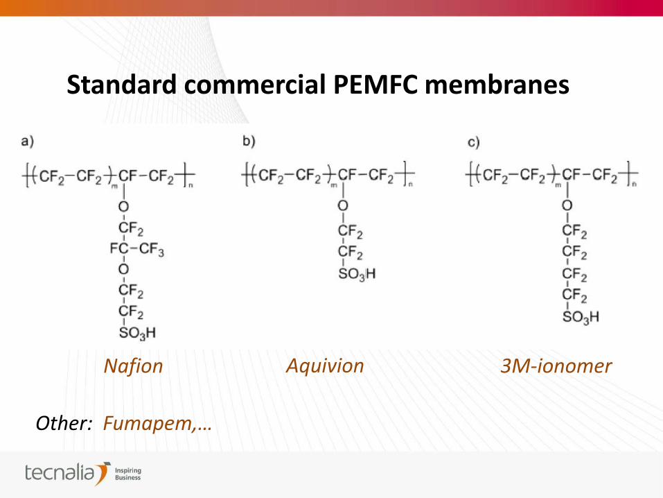
Standard commercial PEMFC membranes
Nafion Aquivion 3M-ionomer
Other: Fumapem,…
CHALLENGES FOR ION CONDUCTING MEMBRANES
Croosover of methanol in DMFC
Temperature resistance (Nafion dehydrates at T>80 °C and RH < 100 %)
COST
Ideal membranes:
- A membrahe with high proton conductivity and low methanol crossover
- A membrane that operates without water at elevated T
DEVELOPMENTS FOR ION CONDUCTING MEMBRANES
Modifications to Nafion to reduce methanol crossover
Addition of loads to Nafion:
Nafion / silica
Nafion / zirconium phospate
Nafion / polyvinyl alcohols
Nafion / sepiolites
Surface modification of Nafion (crosslinking):
Plasma etching
Low dose EB irradiation
Multilayer systems:
Nafion / Nafion-PVDF / Nafion
Results have not met
expectations
DEVELOPMENTS FOR ION CONDUCTING MEMBRANES
Strategies for HT-PEMFC membranes
Modifications to Nafion:
Addition of water-retaining (hydrophilic) additives:
• Non-conducting inorganic particles (SiO2, TiO2)
• Proton conducting inorganic salts (zirconium phosphate)
• Heteropolyacids (phosphotungstic acid)
Eliminate the need for water in a proton exchange membrane
• PBI doped with concentrated phosphoric acid
• Suphonated polymer with adsorbed imidazoles or benzimidazoles
• Inorganic solid acids in a polymeric matrix
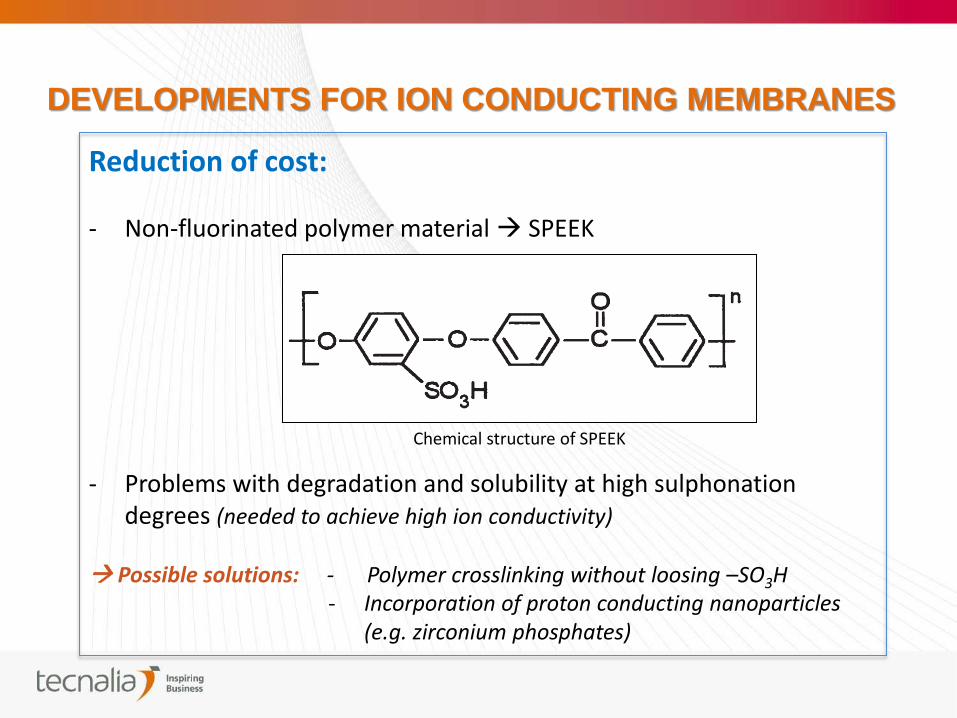
Chemical structure of SPEEK
DEVELOPMENTS FOR ION CONDUCTING MEMBRANES
Reduction of cost: - Non-fluorinated polymer material SPEEK
- Problems with degradation and solubility at high sulphonation degrees (needed to achieve high ion conductivity)
Possible solutions: - Polymer crosslinking without loosing –SO3H - Incorporation of proton conducting nanoparticles
(e.g. zirconium phosphates)

THANKS FOR YOUR
ATTENTION