Embed Size (px)
Citation preview

Energy Materials: Solid Oxide Fuel Cells
Alan AtkinsonDepartment of Materials
Imperial College, London SW7 [email protected]

Key questions
• Where is the UK in relation to the current state of the art of materials technologies in SOFC?
• Where and how can the UK really make a difference in 'meeting the challenge' and become world leaders?
• What are the next steps the UK should be taking to secure business in this area

• Cost – Cheaper materials– Higher performance– Cheaper manufacturing– Simpler systems
• Durability– Thermo-chemical stability– Thermo-mechanical stability– Lower operating temperatures– Resistance to “poison” impurities– Tolerance to abnormal operation– Tolerance of wider range of fuels– Accelerated testing
Main issues

Contents
• Summary of SOFC technology • Status of UK in relation to world activity• Look at some problem issues• Opportunities for UK SOFC

Applications for SOFC• “Large” stationary electrical power (50 kW -10 MW)
– high electrical efficiency– pressurisation and bottoming gas turbine (SOFT-GT)
• “Intermediate” CHP (5-50 kW)– high overall efficiency e.g. in hotels, offices– high grade waste heat
• “Small” CHP (<5 kW)– high overall efficiency e.g. domestic
• Uninterruptible power supplies• Mobile Auxiliary Power Units (APU)
– “Intermediate” size systems for boats, planes and trains– “Small” systems for road vehicles– battery/SOFC hybrid
• Micro power systems for electronics

Technology comparison for stationary power
0
10
20
30
40
50
60
70
80
90
100
0 1 2 3 4 5
reciprocating
GTμGT
SOFC
SOFC-GT
log10(kWe)
Ele
ctric
al e
ffici
ency
(%LH
V n
at. g
as)

Fuels for SOFCs• SOFCs work well on H2, but a key feature is ability to use
CO• Hydrocarbon fuels need pre-reforming to H2+CO
– natural gas– LPG, propane, butane– alcohols– diesel, gasoline
• Steam reforming or catalytic POx (lowers efficiency)– needs no shift reactor or CO clean-up
• S removal required to < 10 wt ppm • Biofuels give C-neutral operation

Typical materials used in SOFC• Electrolyte
– fast oxygen ion conductor (e.g.YSZ)
• Cathode– oxygen reduction catalyst,
oxygen ion conductor, electronic conductor
• single phase perovskite La0.8Sr0.2MnO3 (LSM)La0.8Sr0.2Fe0.8Co0.2O3 (LSCF)
• composite (e.g. LSM/YSZ)
• Anode– oxidation catalyst, oxygen ion
conductor, electronic conductor• composite (e.g. Ni/YSZ)
• Interconnect/bipolar plate– electronic conductor
• La0.8Sr0.2CrO3, Cr alloy, stainless steel
Electrolyte
anode
cathode
O2 e-
O2-
e- H2

SOFC performance goal
Current density (A cm-2)
V per cell
1
0.7
1
ASR = (V0-V)/I = 0.3 ohm cm2 Power density = V×I
Current density (A cm-2)P
ower
den
sity
(W c
m-2
)
0.7
1
Useful power = 0.7 W cm-2
Peak power
Single cell data do not usually include interconnection losses

Design and operating temperature
B.C.H. Steele, Phil. Trans. R. Soc. London A (1996)

SOFC types: Siemens-Westinghouse Tubularoperating temperature 1000° C
Ni /YSZ
Porous LSM extruded and sintered support tube
LCCr interconnect by plasma spray
8YSZ
Siemens-Westinghouse
Advantages•Reliable•Proven durability•“No seals”•Tested to 250 kW•Suited to stationary hybrid operation
Disadvantages•Expensive
–support tube•Low volumetric power density
Status:
Siemens has withdrawn from SOFC (technology for sale)
Very similar technology under development by Toto (Japan)

Other tubular SOFC“Micro” tubular
•Small diameter•Good thermal cycling•Difficult current collection
“Segmented in series” tubular•Larger voltage per tube•Inert support with thick film cells•Long current path•Cell formation difficult
Segmented in series (integrated planar) tube•Rolls-Royce Fuel Cell Systems•Low cost flat support tube•Screen-printed cells•High volumetric power density
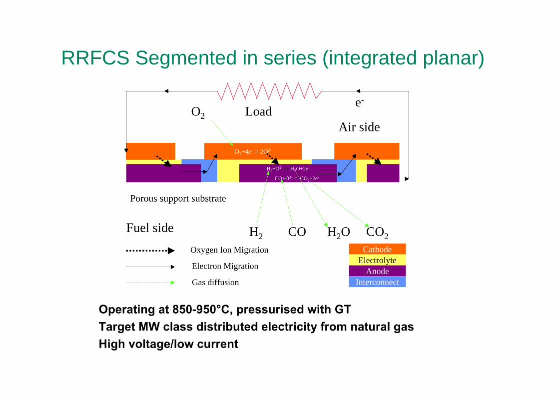
RRFCS Segmented in series (integrated planar)
Porous support substrate
O2+4e- = 2O2-
H2+O2- = H2O+2e-
CO+O2- = CO2+2e-
e-Load
Air side
Fuel side H2 CO H2O CO2
O2
Cathode
AnodeElectrolyte
Interconnect
Oxygen Ion Migration
Electron Migration
Gas diffusion
Operating at 850-950°C, pressurised with GTTarget MW class distributed electricity from natural gasHigh voltage/low current

Planar SOFCAdvantages
•Higher volumetric power density•Simpler manufacture-cheap
Disadvantages•Edge sealing and manifolds•Current collection•Assembly tolerances

Types of planar SOFCElectrolyte supported
•Needs thick electrolyte for strength•Typical 900°C operation•Expensive metallic interconnect
Anode supported•Most Popular•Needs thick anode for strength•Typical 750-850°C operation•Corrosion of interconnect
Metal supported•Robust•Operate to lower T (with alternative electrolyte)
200 micron 8YSZ
50 micron porous Ni/YSZ anode
50 micron porous LSM/YSZ cathode

Typical anode-supported planar SOFC
Cross sectionStack (Versa Power)

Ceres Power Metal-supported SOFC• Ce0.9Gd0.1O2-x electrolyte.
• Cr ferritic stainless steel foil support
• 500-600°C operation
• 1kWe domestic CHP
Advantages• Gas sealing• Mechanical strength• Scaling up
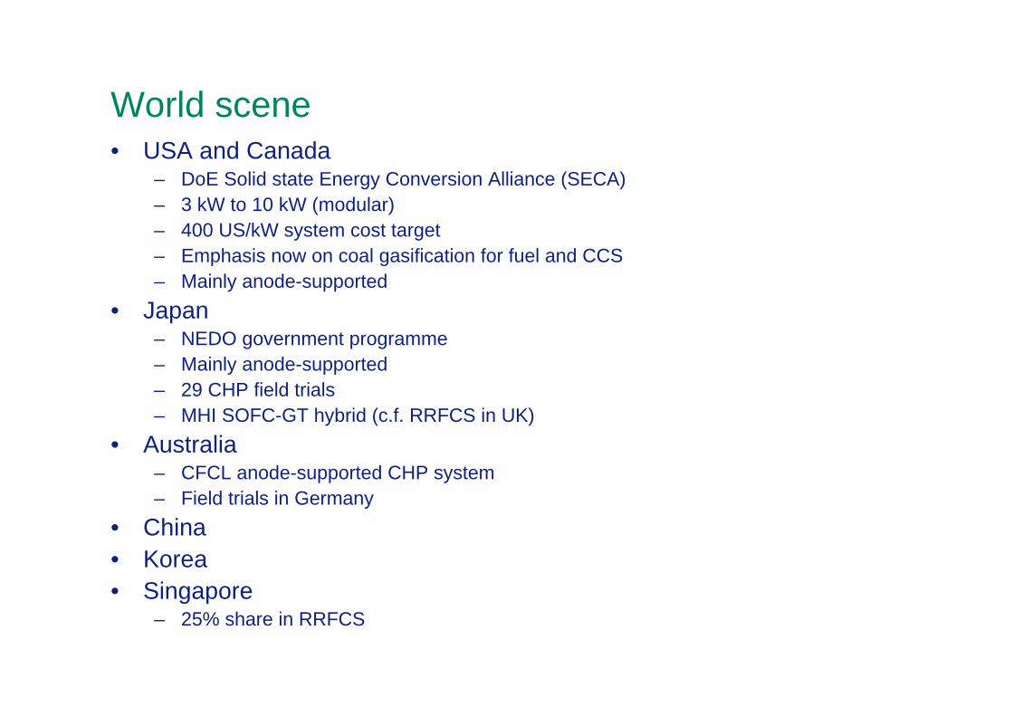
World scene• USA and Canada
– DoE Solid state Energy Conversion Alliance (SECA)– 3 kW to 10 kW (modular) – 400 US/kW system cost target– Emphasis now on coal gasification for fuel and CCS– Mainly anode-supported
• Japan– NEDO government programme– Mainly anode-supported– 29 CHP field trials– MHI SOFC-GT hybrid (c.f. RRFCS in UK)
• Australia– CFCL anode-supported CHP system – Field trials in Germany
• China• Korea• Singapore
– 25% share in RRFCS

SOFC Industry in Europe
1 kWe prototype0.5-5 kWe APUEnerday/Webasto (D)
Field tests1 kWe CHPelectrolyte-supported
Hexis (CH)
1 kW stack validatedAnode-supportedSOFC Power (I)
Demonstrated system with 50/50 electricity/heat
1 kWe domestic CHPLow T metal-supported
Ceres Power (UK)
Building 125 kW pressurised system
1-10 MWe IPSOFCRRFCS (UK)
20 kWe system achieved250 kWe CHP and ship APUTopsoe stacks
Wartsila
Can purchase 0.5 kWeElectrolyte-supportedStaxera (D)
Partner with Wartsila(Finland)
Anode-supported, 1kWe stacksTopsoe Fuel Cell (DK)
Partner in Staxera and with CFCL (Aus)
Materials and cells (electrolyte and anode supported)
H.C. Stark (D)
StatusTechnologyCompany

Current Trends• Lower costs
– lower operating temperatures (less expensive materials)– simpler manufacturing (co-sintering)– Simpler systems
• Increase performance– higher conductivity electrolyte– more active electrodes– Nano-structured materials?
• Increase durability (degradation < 1%/kh)– lower operating temperatures– Resistance to Cr poisoning
• More robust (faster start-up, fuel flexibility, thermal cycling)– metal-supported– oxidation-tolerant anodes– direct hydrocarbon operation (minimise steam requirement)

H2
first operationinitial reduction
NiO + H2 → Ni + H2O
SOFC
fuel failurefuel over-utilization
high pO2
oxidation
Ni + 1/2O2 → NiO
operation restoredre-reduction
NiO + H2 → Ni + H2O
operation
H2 + O-2 → H2O + 2e-
Anode redox problems: Ni-based cermets

Ni cermet redox dimensional changes
NiNiO NiO
volume -41%volume +69.6%reduction oxidationSingle particle
T. Klemensoe et. al, J. Electrochem. Soc., 152, A2186 (2005).
NiO-YSZ Ni-YSZ
little/negligible shrinkage
~ 1% elongation
oxidation strain
NiO-YSZreduction oxidationAnode composite
Experiments

Cr poisoning of SOFC cathode
I. Vinke, SOFC IX, 2007
•Cr vapour species released from steel interconnect and deposit at cathode
•Details of mechanism unclear

Acal Energy AFC Energy Bac 2 BaxiBOC British Midlands Calor Gas CenexCeramic Fuel Cells Ceres Power City University CMR Fuel Cells Diverse Energy E.On
FlexitallicFuel Cell Application Facility Fuel Cell Control Intelligent Energy Johnson Matthey Logan Energy The Micropower Council Philip Sharman PorvairRenew Tees Valley Rolls-Royce Fuel Cells Systems Unitec Ceramics University of Birmingham Valeswood


• Aims– address key technical barriers facing the UK fuel cell industry.– Encompass PEM and SOFC – To develop high quality researchers trained in fuel cell technology.– To communicate research outputs.
• Universities– Imperial College– Newcastle– Nottingham– St Andrews
• Industry– Rolls-Royce Fuel Cell Systems Ltd– Ceres Power Ltd– Johnson Matthey– Defence Science and Technology Laboratory
• Status– 3 years into first phase
EPSRC Supergen Fuel Cells Consortium

(La,Sr)(Cr,Mn)O3 modified anode on CH4
St Andrews
0
0.2
0.4
0.6
0.8
1
1.2
0
100
200
300
400
500
600
700
800
0 0.5 1 1.5 2 2.5
Vol
tage
(V)
Pow
er D
ensi
ty (m
W c
m-2
)
Current Density (A cm-2)
humidified (3% H2O) CH4 at: (○) at 973 K and (∆) at 1073 K.

Wish list for materials• Electrolytes for lowering T or increasing power density
– ScSZ, apatites, proton conductors, others?• Cathodes
– higher activity (particularly at <700°C)– Cr resistance
• Anodes– improving tolerance of Ni-based anodes to redox, C (and S?)– oxide (or other compound) anodes?– direct (or low steam) hydrocarbon operation
• Interconnectors/current collectors– improved oxidation/corrosion resistance and strength– low Cr volatility, coatings– high conductivity (>1000 S cm-1) oxides?
• Simpler (cheaper) manufacturing• Science to underpin the above
– modelling from atomistic to system scales– mechanical properties– in situ diagnostics– Degradation mechanisms
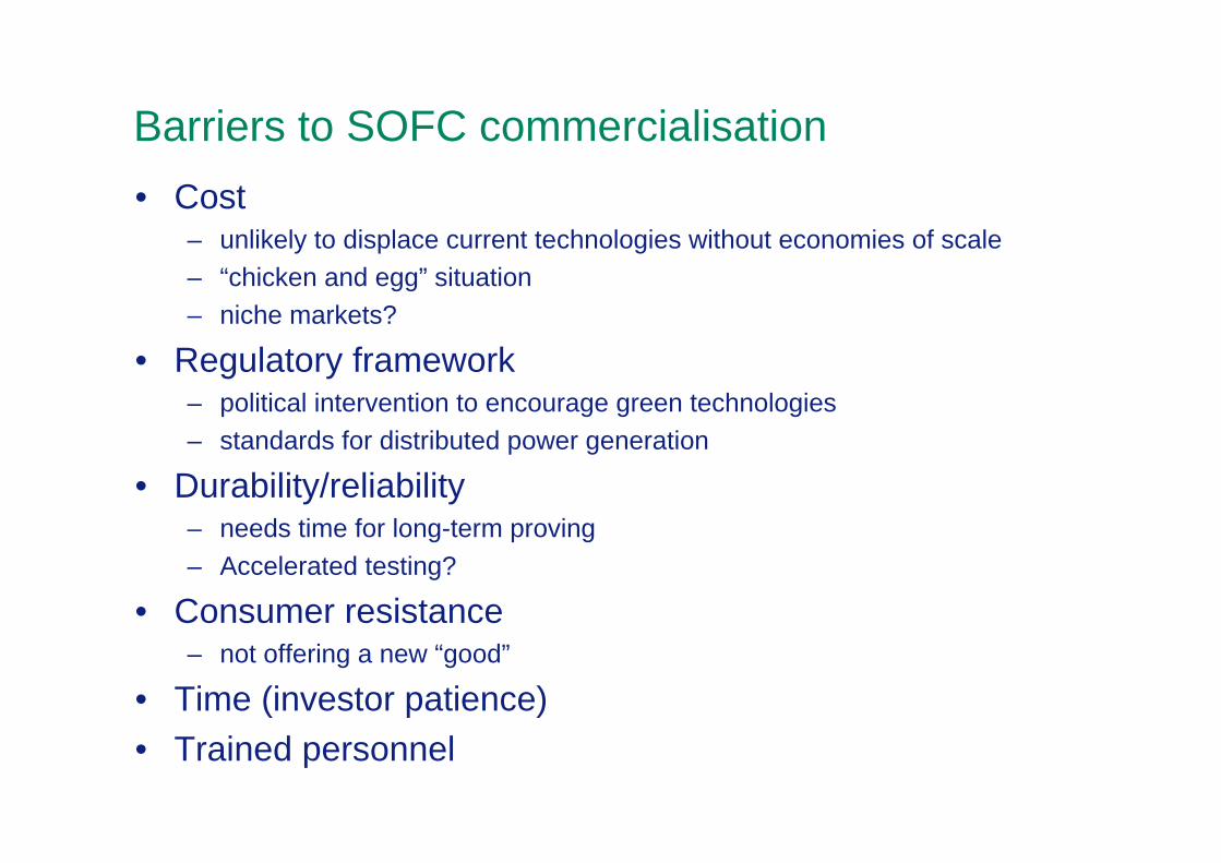
Barriers to SOFC commercialisation• Cost
– unlikely to displace current technologies without economies of scale– “chicken and egg” situation– niche markets?
• Regulatory framework– political intervention to encourage green technologies– standards for distributed power generation
• Durability/reliability– needs time for long-term proving– Accelerated testing?
• Consumer resistance – not offering a new “good”
• Time (investor patience)• Trained personnel

SWOT for UK SOFC
• Strengths– 2 world-leading industrial companies and technologies– Strong science base (particularly in cell materials and modelling)
• Weaknesses– No national labs in support (cf. Juelich, Risoe, ECN, CEA in Europe)– No manufacturer/developer of interconnect steels (Thyssen-Krupp)– Limited capability in BoP?
• Opportunities– Increasing energy prices– EU-funded demonstrations (JTI)– Related technologies (electrolysers, gas separation membranes)
• Threats– Poor economic outlook for investment– Competition catches up/overtakes– Unable to meet cost and durability goals quickly enough

Conclusions• UK has 2 world-leading companies and a strong relevant
science base• This constitutes an excellent opportunity• There are no “show stoppers” in materials within the state-
of-the-art UK technologies.• Improvement is required in cost and durability• Some other capabilities are desirable (particularly for
anodes)• Reaching the critical demonstration stage where costs
increase.

Thank you for your attention!