Embed Size (px)
Citation preview
1
Materials and metals in MSR
Presented by Victor Ignatiev
National Research Center “Kurchatov Institute”
123182, Kurchatov sq., 1, Moscow, Russia [email protected]
MSR Summer school, July 2-4, 2017, Lecco, Italy
2
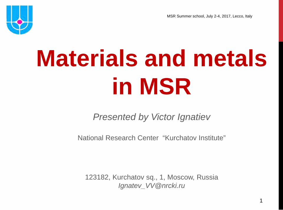
All GEN IV reactors require higher operating temperatures and / or radiation doses. The higher operating temperatures / dose rate require materials increased high temperature strength, thermal stability and irradiation resistance.
20-40 dpa
50-80 dpa
20-40 dpa
50-130 dpa
90-150 dpa
MOLTEN SALT FLUORIDES
3 3
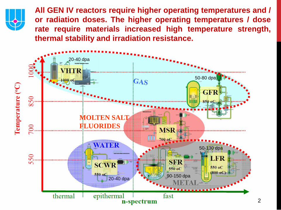
Different Reactor Concepts using Molten Salt are Discussed at GIF
MSR pSSC Meetings • Within the GIF, research is performed on the MSR
concepts, under the MOU signed by Euratom, France, the Russian Federation, Switzerland and USA. China, Australia, Korea, Japan and contribute as observers.
• Two fast spectrum MSR concepts are being studied, large power units based on homogeneous core with liquid fluoride-salt circulating fuel: MSFR design in France, Euratom and Switzerland as well as MOSART concept in the Russian Federation. R&D studies are on-going in order to verify that fast spectrum MSR systems satisfy the goals of Gen-IV reactors in terms of sustainability, non-proliferation, safety and waste management.
• The US is working on solid fuel FHR (Fluoride-salt-cooled High-temperature Reactor) as well as liquid fueled MCFR (Molten Chloride salt Fast Reactor)
• China, as observer in the pSSC of the MSR, is working on FHR and TMSR (Thorium Molten fluoride Salt thermal Reactor) graphite moderated designs.
4
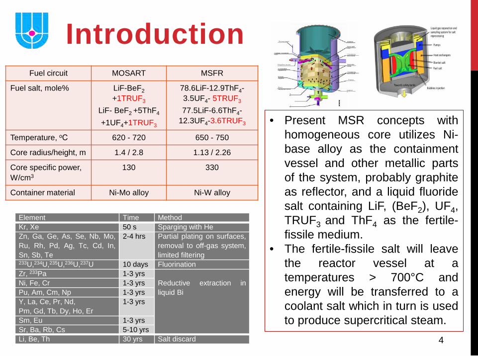
Introduction Fuel circuit MOSART MSFR
Fuel salt, mole% LiF-BeF2 +1TRUF3
LiF- BeF2 +5ThF4
+1UF4+1TRUF3
78.6LiF-12.9ThF4-3.5UF4- 5TRUF3 77.5LiF-6.6ThF4-
12.3UF4-3.6TRUF3
Temperature, оС 620 - 720 650 - 750
Core radius/height, m 1.4 / 2.8 1.13 / 2.26
Core specific power, W/cm3
130 330
Container material Ni-Mo alloy Ni-W alloy
Element Time Method Kr, Xe 50 s Sparging with He Zn, Ga, Ge, As, Se, Nb, Mo, Ru, Rh, Pd, Ag, Tc, Cd, In, Sn, Sb, Te
2-4 hrs Partial plating on surfaces, removal to off-gas system, limited filtering
233U,234U,235U,236U,237U 10 days Fluorination Zr, 233Pa 1-3 yrs
Reductive extraction in liquid Bi
Ni, Fe, Cr 1-3 yrs Pu, Am, Cm, Np 1-3 yrs Y, La, Ce, Pr, Nd, Pm, Gd, Tb, Dy, Ho, Er
1-3 yrs
Sm, Eu 1-3 yrs Sr, Ba, Rb, Cs 5-10 yrs Li, Be, Th 30 yrs Salt discard
• Present MSR concepts with homogeneous core utilizes Ni-base alloy as the containment vessel and other metallic parts of the system, probably graphite as reflector, and a liquid fluoride salt containing LiF, (BeF2), UF4, TRUF3 and ThF4 as the fertile-fissile medium.
• The fertile-fissile salt will leave the reactor vessel at a temperatures > 700°C and energy will be transferred to a coolant salt which in turn is used to produce supercritical steam.
5
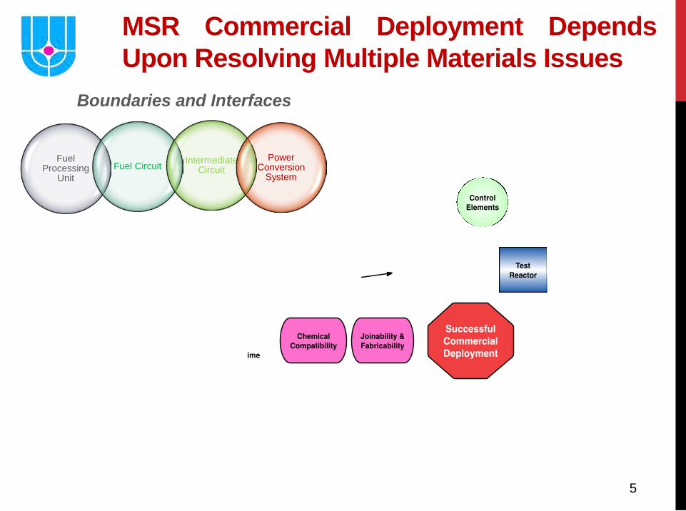
MSR Commercial Deployment Depends Upon Resolving Multiple Materials Issues
Fuel Processing
Unit Fuel Circuit Intermediate
Circuit Power
Conversion System
Boundaries and Interfaces
6 6
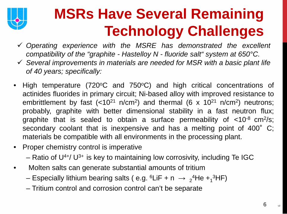
MSRs Have Several Remaining Technology Challenges
• High temperature (720oC and 750oC) and high critical concentrations of actinides fluorides in primary circuit; Ni-based alloy with improved resistance to embrittlement by fast (<1021 n/cm2) and thermal (6 x 10²¹ n/cm2) neutrons; probably, graphite with better dimensional stability in a fast neutron flux; graphite that is sealed to obtain a surface permeability of <10-8 cm2/s; secondary coolant that is inexpensive and has a melting point of 400°C; materials be compatible with all environments in the processing plant.
• Proper chemistry control is imperative – Ratio of U4+/ U3+ is key to maintaining low corrosivity, including Te IGC
• Molten salts can generate substantial amounts of tritium – Especially lithium bearing salts ( e.g. 6LiF + n → 24He +1
3HF) – Tritium control and corrosion control can’t be separate
Operating experience with the MSRE has demonstrated the excellent compatibility of the “graphite - Hastelloy N - fluoride salt“ system at 650°C.
Several improvements in materials are needed for MSR with a basic plant life of 40 years; specifically:
7
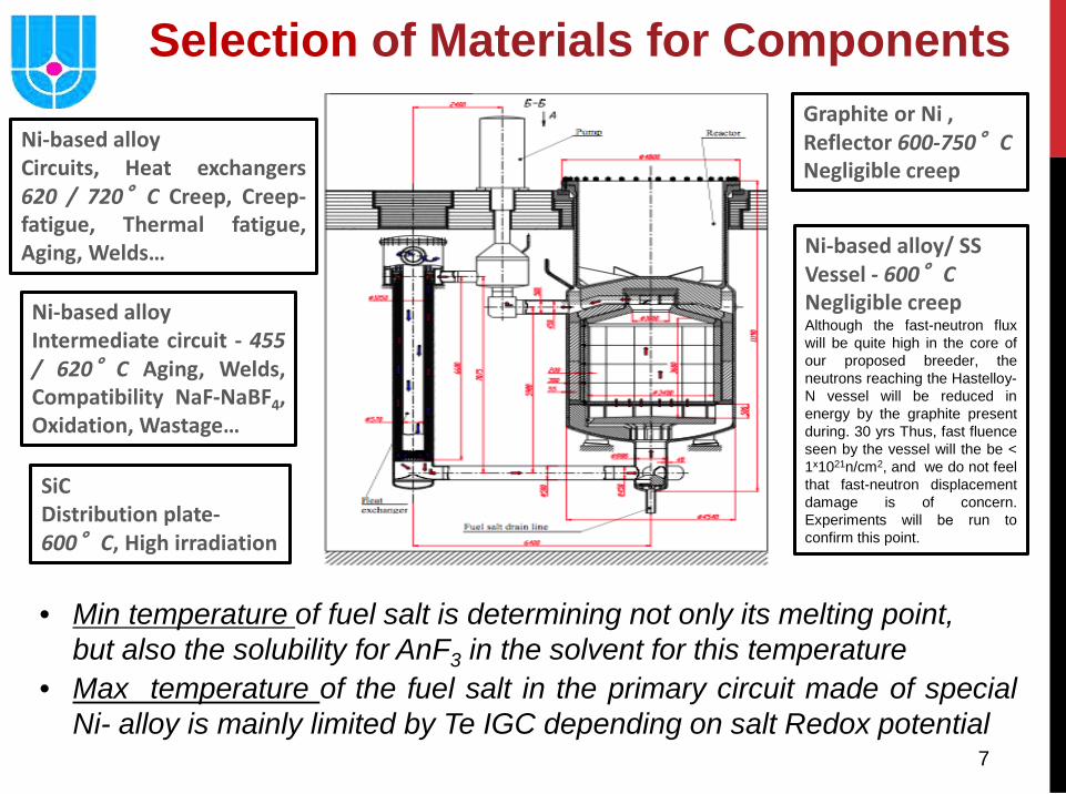
• Max temperature of the fuel salt in the primary circuit made of special Ni- alloy is mainly limited by Te IGC depending on salt Redox potential
Ni-based alloy Circuits, Heat exchangers 620 / 720°C Creep, Creep-fatigue, Thermal fatigue, Aging, Welds…
Ni-based alloy Intermediate circuit - 455 / 620°C Aging, Welds, Compatibility NaF-NaBF4, Oxidation, Wastage…
SiC Distribution plate- 600°C, High irradiation
Graphite or Ni , Reflector 600-750°C Negligible creep
Ni-based alloy/ SS Vessel - 600°C Negligible creep Although the fast-neutron flux will be quite high in the core of our proposed breeder, the neutrons reaching the Hastelloy-N vessel will be reduced in energy by the graphite present during. 30 yrs Thus, fast fluence seen by the vessel will the be < 1х1021n/cm2, and we do not feel that fast-neutron displacement damage is of concern. Experiments will bе run to confirm this point.
Selection of Materials for Components
• Min temperature of fuel salt is determining not only its melting point, but also the solubility for AnF3 in the solvent for this temperature
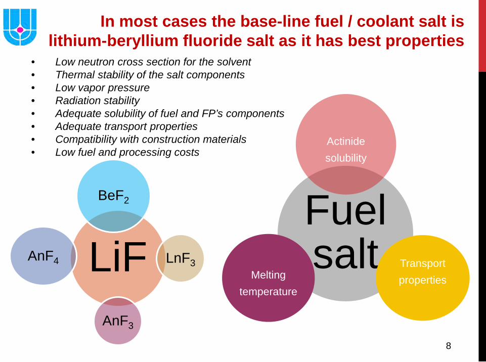
8
LiF
BeF2
LnF3
AnF3
AnF4
Fuel salt
Actinide solubility
Transport properties
Melting temperature
In most cases the base-line fuel / coolant salt is lithium-beryllium fluoride salt as it has best properties
• Low neutron cross section for the solvent • Thermal stability of the salt components • Low vapor pressure • Radiation stability • Adequate solubility of fuel and FP’s components • Adequate transport properties • Compatibility with construction materials • Low fuel and processing costs
9
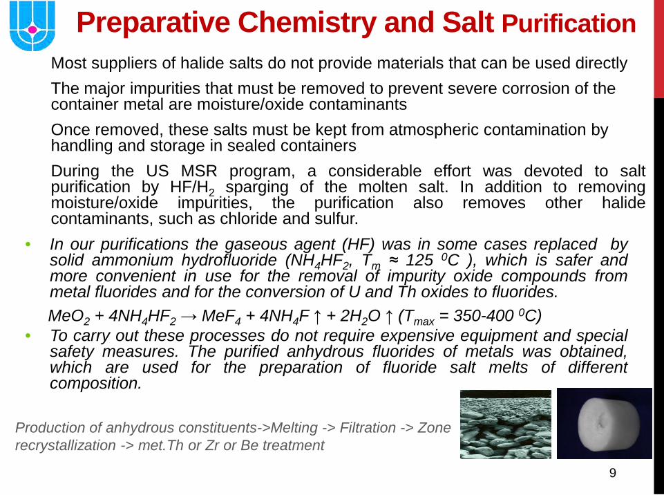
Preparative Chemistry and Salt Purification Most suppliers of halide salts do not provide materials that can be used directly The major impurities that must be removed to prevent severe corrosion of the container metal are moisture/oxide contaminants Once removed, these salts must be kept from atmospheric contamination by handling and storage in sealed containers During the US MSR program, a considerable effort was devoted to salt purification by HF/H2 sparging of the molten salt. In addition to removing moisture/oxide impurities, the purification also removes other halide contaminants, such as chloride and sulfur.
• In our purifications the gaseous agent (HF) was in some cases replaced by solid ammonium hydrofluoride (NH4HF2, Tm ≈ 125 0C ), which is safer and more convenient in use for the removal of impurity oxide compounds from metal fluorides and for the conversion of U and Th oxides to fluorides.
MeO2 + 4NH4HF2 → MeF4 + 4NH4F ↑ + 2H2O ↑ (Tmax = 350-400 0C) • To carry out these processes do not require expensive equipment and special
safety measures. The purified anhydrous fluorides of metals was obtained, which are used for the preparation of fluoride salt melts of different composition.
Production of anhydrous constituents->Melting -> Filtration -> Zone recrystallization -> met.Th or Zr or Be treatment
10
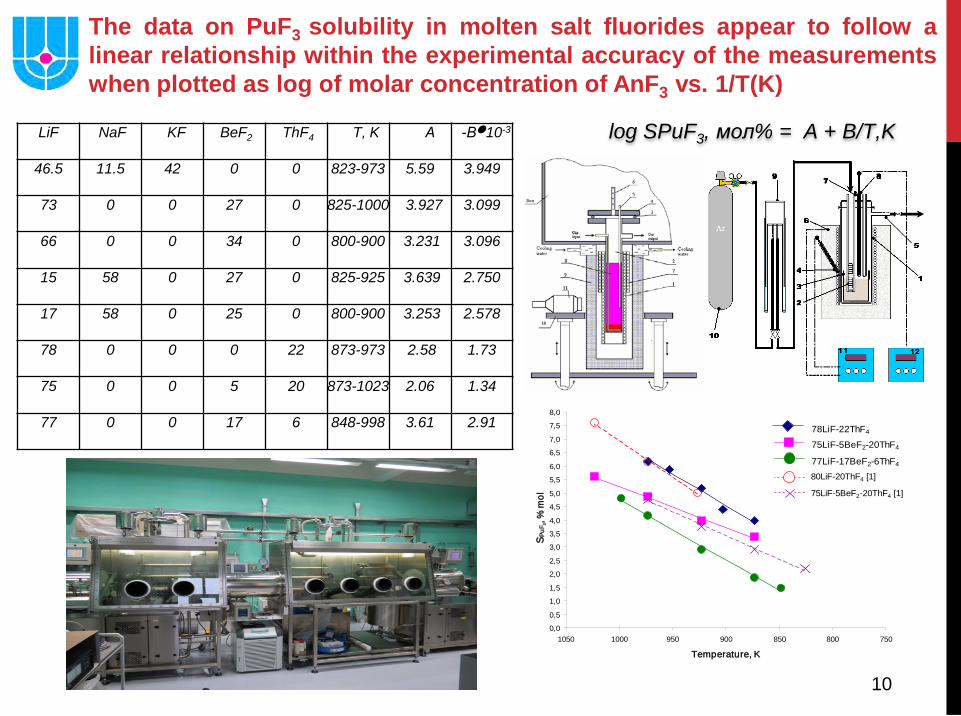
LiF NaF KF BeF2 ThF4 T, K А -В●10-3
46.5 11.5 42 0 0 823-973 5.59 3.949
73 0 0 27 0 825-1000 3.927 3.099
66 0 0 34 0 800-900 3.231 3.096
15 58 0 27 0 825-925 3.639 2.750
17 58 0 25 0 800-900 3.253 2.578
78 0 0 0 22 873-973 2.58 1.73
75 0 0 5 20 873-1023 2.06 1.34
77 0 0 17 6 848-998 3.61 2.91
The data on PuF3 solubility in molten salt fluorides appear to follow a linear relationship within the experimental accuracy of the measurements when plotted as log of molar concentration of AnF3 vs. 1/T(K)
0,0
0,5
1,0
1,5
2,0
2,5
3,0
3,5
4,0
4,5
5,0
5,5
6,0
6,5
7,0
7,5
8,0
75080085090095010001050
Temperature, K
S PuF
3, %
mol
77LiF-17BeF2-6ThF4
75LiF-5BeF2-20ThF4
78LiF-22ThF4
80LiF-20ThF4 [1]
75LiF-5BeF2-20ThF4 [1]
log SPuF3, мол% = A + B/T,K
11
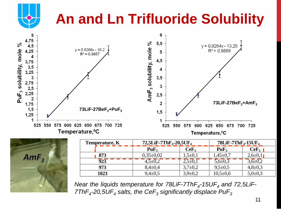
73LiF-27BeF2+AmF3 73LiF-27BeF2+PuF3
Temperature, K 72,5LiF-7ThF4-20,5UF4 78LiF-7ThF4-15UF4 PuF3 CeF3 PuF3 CeF3
873 0,35±0,02 1,5±0,1 1,45±0,7 2,6±0,1 923 4,5±0,2 2,5±0,1 5,6±0,3 3,6±0,2 973 8,4±0,4 3,7±0,2 9,5±0,5 4,8±0,3 1023 9,4±0,5 3,9±0,2 10,5±0,6 5,0±0,3
An and Ln Trifluoride Solubility
Near the liquids temperature for 78LiF-7ThF4-15UF4 and 72,5LiF-7ThF4-20,5UF4 salts, the CeF3 significantly displace PuF3
12
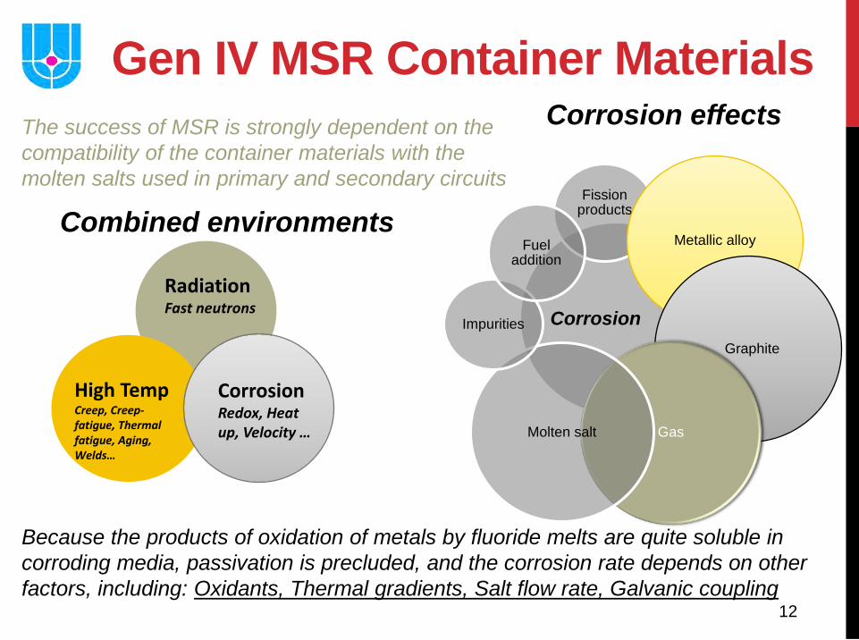
Gen IV MSR Container Materials
Corrosion
Fission products
Metallic alloy
Graphite
Gas Molten salt
Impurities
Fuel addition
Combined environments
Corrosion effects
High Temp Creep, Creep-fatigue, Thermal fatigue, Aging, Welds…
Radiation Fast neutrons
Corrosion Redox, Heat up, Velocity …
The success of MSR is strongly dependent on the compatibility of the container materials with the molten salts used in primary and secondary circuits
Because the products of oxidation of metals by fluoride melts are quite soluble in corroding media, passivation is precluded, and the corrosion rate depends on other factors, including: Oxidants, Thermal gradients, Salt flow rate, Galvanic coupling
13
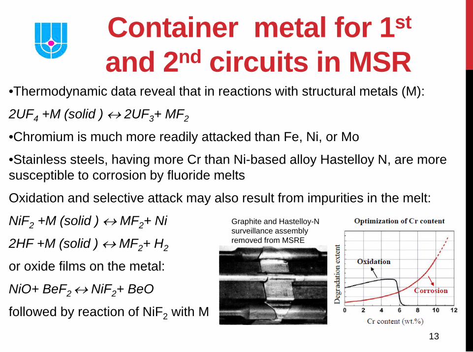
Container metal for 1st and 2nd circuits in MSR
•Thermodynamic data reveal that in reactions with structural metals (M):
2UF4 +M (solid ) ↔ 2UF3+ MF2
•Chromium is much more readily attacked than Fe, Ni, or Mo
•Stainless steels, having more Cr than Ni-based alloy Hastelloy N, are more susceptible to corrosion by fluoride melts
Oxidation and selective attack may also result from impurities in the melt:
NiF2 +M (solid ) ↔ MF2+ Ni
2HF +M (solid ) ↔ MF2+ H2
or oxide films on the metal:
NiO+ BeF2 ↔ NiF2+ BeO
followed by reaction of NiF2 with M
Graphite and Hastelloy-N surveillance assembly removed from MSRE
14
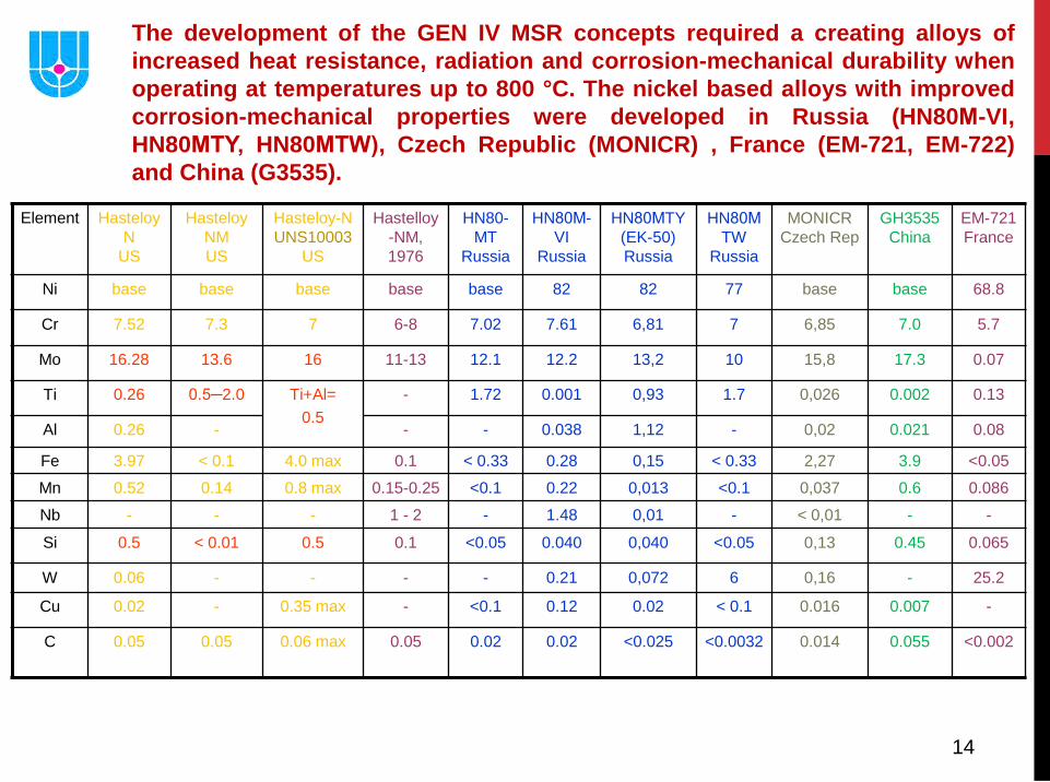
The development of the GEN IV MSR concepts required a creating alloys of increased heat resistance, radiation and corrosion-mechanical durability when operating at temperatures up to 800 °C. The nickel based alloys with improved corrosion-mechanical properties were developed in Russia (HN80М-VI, HN80МТY, HN80МТW), Czech Republic (MONICR) , France (EM-721, EM-722) and China (G3535).
Element Hasteloy N
US
Hasteloy NM US
Hasteloy-N UNS10003
US
Hastelloy-NM, 1976
HN80-MT
Russia
HN80М- VI
Russia
HN80МTY (EK-50) Russia
HN80М TW
Russia
MONICR Czech Rep
GH3535 China
EM-721 France
Ni base base base base base 82 82 77 base base 68.8
Cr 7.52 7.3 7 6-8 7.02 7.61 6,81 7 6,85 7.0 5.7
Mo 16.28 13.6 16 11-13 12.1 12.2 13,2 10 15,8 17.3 0.07
Ti 0.26 0.5─2.0 Ti+Al= 0.5
- 1.72 0.001 0,93 1.7 0,026 0.002 0.13
Al 0.26 - - - 0.038 1,12 - 0,02 0.021 0.08
Fe 3.97 < 0.1 4.0 max 0.1 < 0.33 0.28 0,15 < 0.33 2,27 3.9 <0.05
Mn 0.52 0.14 0.8 max 0.15-0.25 <0.1 0.22 0,013 <0.1 0,037 0.6 0.086
Nb - - - 1 - 2 - 1.48 0,01 - < 0,01 - -
Si 0.5 < 0.01 0.5 0.1 <0.05 0.040 0,040 <0.05 0,13 0.45 0.065
W 0.06 - - - - 0.21 0,072 6 0,16 - 25.2
Cu 0.02 - 0.35 max - <0.1 0.12 0.02 < 0.1 0.016 0.007 -
C 0.05 0.05 0.06 max 0.05 0.02 0.02 <0.025
<0.0032
0.014 0.055 <0.002
15
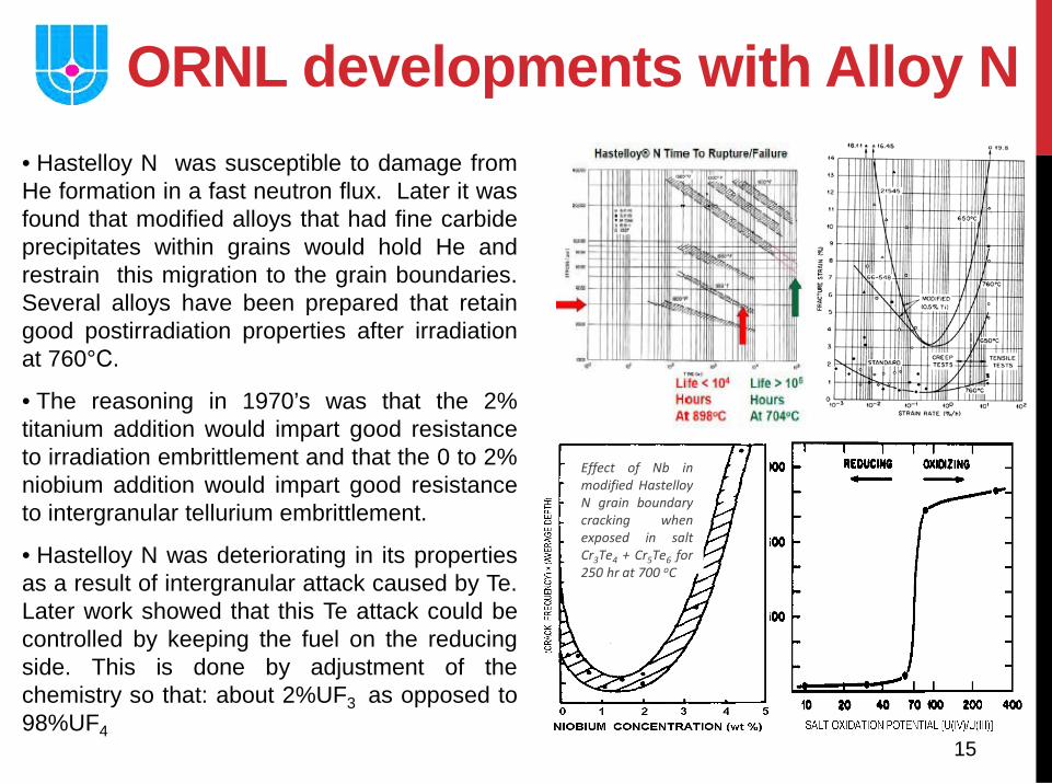
ORNL developments with Alloy N • Hastelloy N was susceptible to damage from He formation in a fast neutron flux. Later it was found that modified alloys that had fine carbide precipitates within grains would hold He and restrain this migration to the grain boundaries. Several alloys have been prepared that retain good postirradiation properties after irradiation at 760°С.
• The reasoning in 1970’s was that the 2% titanium addition would impart good resistance to irradiation embrittlement and that the 0 to 2% niobium addition would impart good resistance to intergranular tellurium embrittlement.
• Hastelloy N was deteriorating in its properties as a result of intergranular attack caused by Te. Later work showed that this Te attack could be controlled by keeping the fuel on the reducing side. This is done by adjustment of the chemistry so that: about 2%UF3 as opposed to 98%UF4
Effect of Nb in modified Hastelloy N grain boundary cracking when exposed in salt Cr3Te4 + Cr5Te6 for 250 hr at 700 oC
16
• The reaction of steam with Li2BeF4 yields HF and BeO H20(g) + BeF2(P) →BeO(c) + 2HF(g) • Both H20 and HF are likely to corrode the metal in contact
with the salt; corrosion-product fluorides will dissolve or be otherwise carried by the salt. Since BeO is only very slightly soluble in Li2BeF4, a large in-leakage of steam would soon lead to the precipitation of BeO in the salt circuit.
• Moisture in the air will also react, as does steam, with Li2BeF4. The molten Li2BeF4 can, if necessary, be freed of oxide by treatment at elevated temperatures with anhydrous HF
• From Li2BeF4, metallic Li, Na, or K react to precipitate Be metal, but the reaction is not highly exothermic.
MSR Coolant Behavior
17
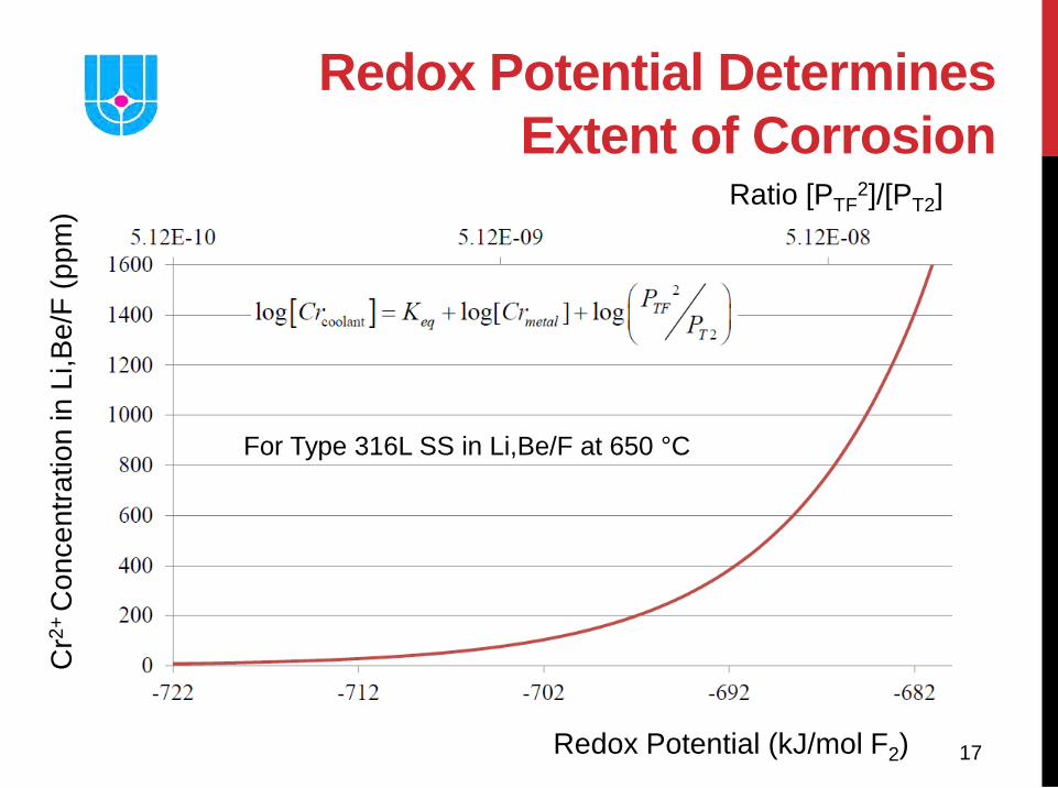
Redox Potential Determines Extent of Corrosion
For Type 316L SS in Li,Be/F at 650 °C
Redox Potential (kJ/mol F2)
Cr2
+ C
once
ntra
tion
in L
i,Be/
F (p
pm) Ratio [PTF
2]/[PT2]
18
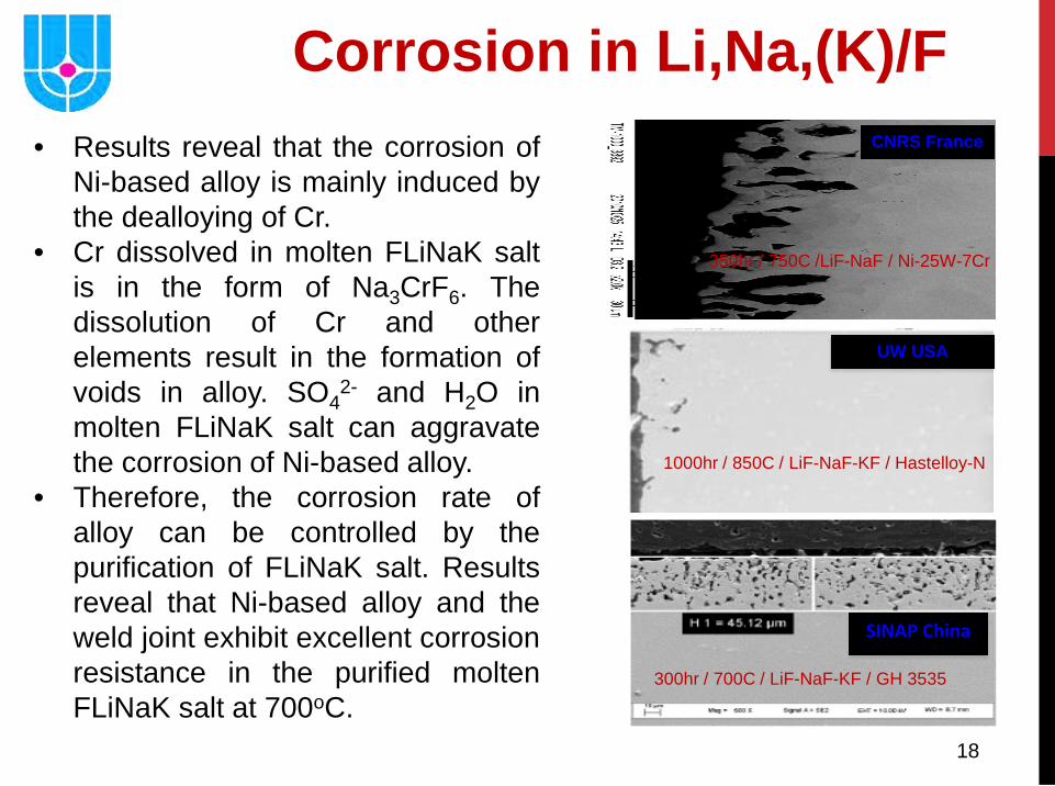
Corrosion in Li,Na,(K)/F CNRS France
350hr / 750C /LiF-NaF / Ni-25W-7Cr
1000hr / 850C / LiF-NaF-KF / Hastelloy-N
UW USA
SINAP China
300hr / 700C / LiF-NaF-KF / GH 3535
• Results reveal that the corrosion of Ni-based alloy is mainly induced by the dealloying of Cr.
• Cr dissolved in molten FLiNaK salt is in the form of Na3CrF6. The dissolution of Cr and other elements result in the formation of voids in alloy. SO4
2- and H2O in molten FLiNaK salt can aggravate the corrosion of Ni-based alloy.
• Therefore, the corrosion rate of alloy can be controlled by the purification of FLiNaK salt. Results reveal that Ni-based alloy and the weld joint exhibit excellent corrosion resistance in the purified molten FLiNaK salt at 700oC.
19
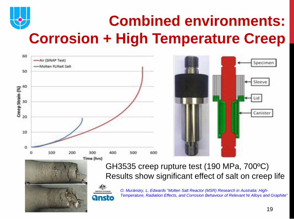
GH3535 creep rupture test (190 MPa, 700ºC) Results show significant effect of salt on creep life
Combined environments: Corrosion + High Temperature Creep
O. Muránsky, L. Edwards “Molten Salt Reactor (MSR) Research in Australia: High-Temperature, Radiation Effects, and Corrosion Behaviour of Relevant Ni Alloys and Graphite”
20
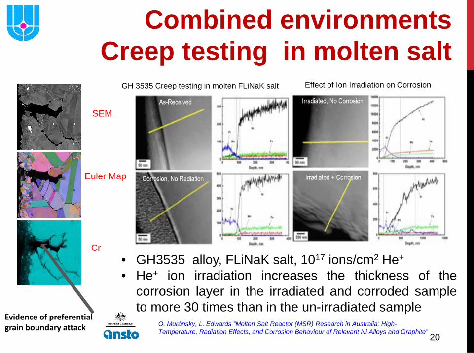
GH 3535 Creep testing in molten FLiNaK salt
SEM
Euler Map
Cr
Combined environments Creep testing in molten salt
• GH3535 alloy, FLiNaK salt, 1017 ions/cm2 He+
• He+ ion irradiation increases the thickness of the corrosion layer in the irradiated and corroded sample to more 30 times than in the un-irradiated sample
Effect of Ion Irradiation on Corrosion
Evidence of preferential grain boundary attack O. Muránsky, L. Edwards “Molten Salt Reactor (MSR) Research in Australia: High-
Temperature, Radiation Effects, and Corrosion Behaviour of Relevant Ni Alloys and Graphite”
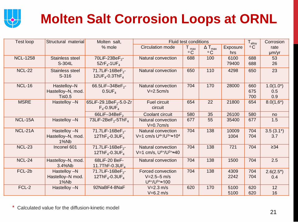
21 * Calculated value for the diffusion-kinetic model
Test loop Structural material Molten salt, % mole
Fluid test conditions Talloy o C
Corrosion rate
μm/yr Circulation mode T max
о С Δ Тmах
о С Exposure
hrs NCL-1258 Stainless steel
S-304L 70LiF-23BeF2-
5ZrF4-1UF4 Natural convection 688 100 6100
79400 688 688
53 26
NCL-22 Stainless steel S-316
71.7LiF-16BeF2- 12UF4-0.3ThF4
Natural convection 650 110 4298 650
23
NCL-16 Hastelloy–N Hastelloy–N, mod.
Ti≤0.5
66.5LiF–34BeF2-0.5UF4
Natural convection V=2.5cm/s
704 170 28000 660 675 700
1.0(1.0*) 0.5 0.9
MSRE Hastelloy –N 65LiF-29.1BeF2-5.0-Zr F4-0.9UF4
Fuel circuit circuit
654 22 21800 654 8.0(1,6*)
66LiF–34BeF2 Coolant circuit 580 35 26100 580 no NCL-15A Hastelloy –N 73LiF-2BeF2-5ThF4 Natural convection
V=0.7cm/s 677 55 35400 677 1.5
NCL-21A Hastelloy –N Hastelloy–N, mod.
1%Nb
71.7LiF-16BeF2-12ThF4-0.3UF4
Natural convection V=1 cm/s U4+/U3+≈104
704 138 10009 1004
704 704
3.5 (3.1*) 3.7
NCL-23 Inconel 601 71.7LiF-16BeF2-12ThF4-0.3UF4
Natural convection V=1 cm/s, U4+/U3+≈40
704 138 721 704 ≥34
NCL-24 Hastelloy–N, mod. 3.4%Nb
68LiF-20 BeF-11.7ThF-0.3UF4
Natural convection 704 138 1500 704 2.5
FCL-2b Hastelloy –N Hastelloy–N mod.
1%Nb
71.7LiF-16BeF2-12ThF4-0.3UF4
Forced convection V=2.5–5 m/s U4+/U3+≈100
704 138 4309 2242
704 704
2.6(2.5*) 0.4
FCL-2 Hastelloy –N
92NaBF4-8NaF V=2.3 m/s V=6.2 m/s
620 170 5100 5100
620 620
12 16
Molten Salt Corrosion Loops at ORNL
22
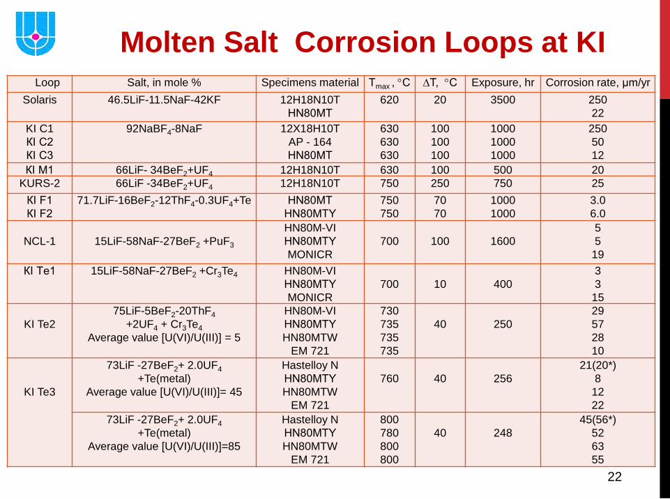
Molten Salt Corrosion Loops at KI Loop Salt, in mole % Specimens material Тmax , °С ∆Т, °С Exposure, hr Corrosion rate, μm/yr
Solaris 46.5LiF-11.5NaF-42KF 12H18N10T HN80МТ
620 20 3500 250 22
KI C1 КI С2 КI С3
92NaBF4-8NaF 12X18H10T AP - 164 HN80МТ
630 630 630
100 100 100
1000 1000 1000
250 50 12
КI M1 66LiF- 34BeF2+UF4 12H18N10T 630 100 500 20 KURS-2 66LiF -34BeF2+UF4 12H18N10T 750 250 750 25
КI F1 КI F2
71.7LiF-16BeF2-12ThF4-0.3UF4+Te HN80МТ HN80МТY
750 750
70 70
1000 1000
3.0 6.0
NCL-1
15LiF-58NaF-27BeF2 +PuF3
HN80M-VI HN80МТY MONICR
700
100
1600
5 5
19 КI Тe1
15LiF-58NaF-27BeF2 +Cr3Te4
HN80M-VI HN80МТY MONICR
700
10
400
3 3
15
KI Te2
75LiF-5BeF2-20ThF4 +2UF4 + Cr3Te4
Average value [U(VI)/U(III)] = 5
HN80M-VI HN80МТY HN80MTW
EM 721
730 735 735 735
40
250
29 57 28 10
KI Te3
73LiF -27BeF2+ 2.0UF4 +Te(metal)
Average value [U(VI)/U(III)]= 45
Hastelloy N HN80МТY HN80MTW
EM 721
760
40
256
21(20*) 8
12 22
73LiF -27BeF2+ 2.0UF4 +Te(metal)
Average value [U(VI)/U(III)]=85
Hastelloy N HN80МТY HN80MTW
EM 721
800 780 800 800
40
248
45(56*) 52 63 55
23
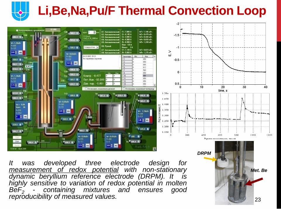
Li,Be,Na,Pu/F Thermal Convection Loop
It was developed three electrode design for measurement of redox potential with non-stationary dynamic beryllium reference electrode (DRPM). It is highly sensitive to variation of redox potential in molten BeF2 - containing mixtures and ensures good reproducibility of measured values.
Met. Be
DRPM
24
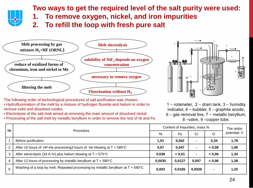
Two ways to get the required level of the salt purity were used: 1. To remove oxygen, nickel, and iron impurities 2. To refill the loop with fresh pure salt
Melt processing by gas mixture H2+HF (ORNL)
reduce of oxidized forms of chromium, iron and nickel to Me
filtering the melt
Melt electrolysis
solubility of NiF2 depends on oxygen
concentration
necessary to remove oxygen
Fluorination without H2
1 − rotameter, 2 – drain tank, 3 – humidity indicator, 4 − bubbler, 5 – graphite anode,
6 – gas removal line, 7 − metallic beryllium, 8 –valve, 9 –copper tube.
The following order of technological procedures of salt purification was chosen: • Hydrofluorination of the melt by a mixture of hydrogen fluoride and helium in order to remove solid and dissolved oxides. • Electrolysis of the salt melt aimed at removing the main amount of dissolved nickel. • Processing of the salt melt by metallic beryllium in order to remove the rest of Ni and Fe.
№ Procedure Content of impurities, mass.% The redox
potential, V Ni Fe Cr O
1 Before purification 1,01 0,042 - 0,34 1,78
2 After 14 hours of HF-He processing3 hours of He blowing at T = 580°C 0,57 0,047 - < 0,08 1,95
3 After electrolysis (34 A·hr) plus helium blowing at T = 575°C 0,038 < 0,01 - < 0,06 1,34
4 After 12 hours of processing by metallic beryllium at T = 580°C 0,0035 0,0127 0,007 < 0,06 1,38
5 Washing of a loop by melt. Repeated processing by metallic beryllium at T = 580°C 0,003 0,0165 0,0026 - 1,25
25
• Solubility has significance of impurities such as moisture react with molten salts to produce metal oxides of much higher melting point and correspondingly lower solubility.
For UF4 fueled systems this reaction is written as: 2H2O+UF4 ↔ 4HF+UO2
• To prevent the loss of uranium from solution and possible accumulation of UO2 precipitate in amounts large enough to pose criticality concerns, 5mole% of ZrF4 was added to the solution of MSRE to getter any oxide impurities through the reaction:
2H2O+ZrF4 ↔ 4HF+ZrO2 • Plutonium as PuF3 shows little tendency to precipitate as
oxide even in the presence of excess BeO and ThO2
MSR Fuel Behavior
26
• Besides solubility concerns with respect to impurity reactions, one must prevent the liquid fuel component from reacting: with container or with moderator graphite. Reactions of the former like as:
UF4 +Cr (solid ) ↔ UF3+ CrF2 and the later:
UF3 +2C ↔ UC2+ 3UF4 were prevented by careful control of the solution redox chemistry which was accomplished by setting the UF4 / UF3 ratio at approximately (50-60)/1. • Additions of metallic Be to the fuel salt to effect the
reduction of the UF4 via: 2UF4 +Be0 ↔ 2UF3+ BeF2
MSR Fuel Behavior
27
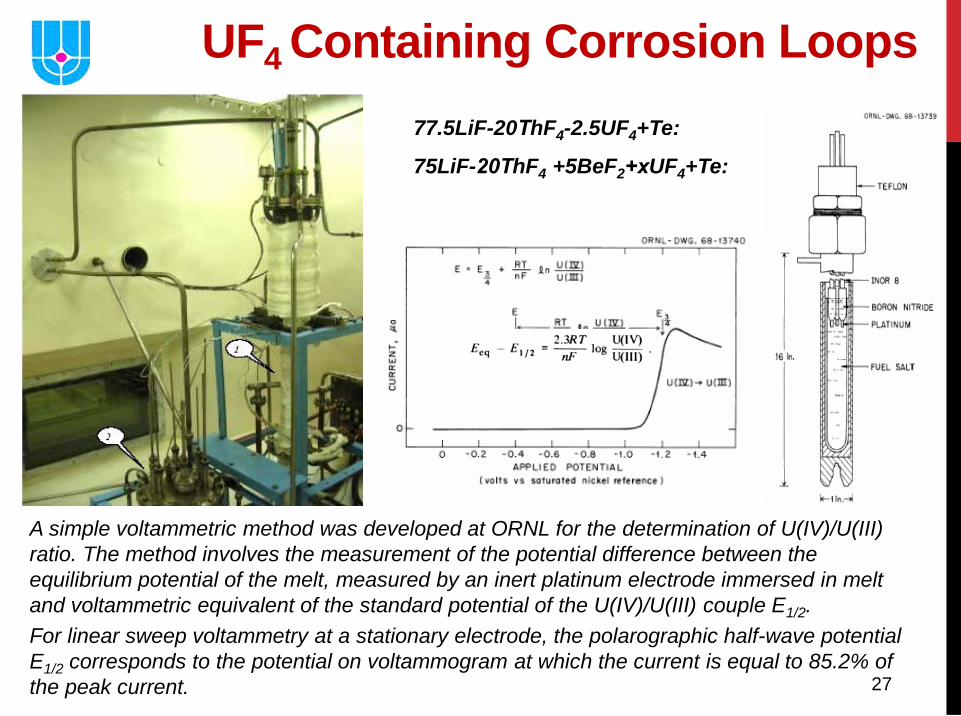
UF4 Containing Corrosion Loops 77.5LiF-20ТhF4-2.5UF4+Te:
75LiF-20ТhF4 +5BeF2+хUF4+Te:
A simple voltammetric method was developed at ORNL for the determination of U(IV)/U(III) ratio. The method involves the measurement of the potential difference between the equilibrium potential of the melt, measured by an inert platinum electrode immersed in melt and voltammetric equivalent of the standard potential of the U(IV)/U(III) couple E1/2. For linear sweep voltammetry at a stationary electrode, the polarographic half-wave potential E1/2 corresponds to the potential on voltammogram at which the current is equal to 85.2% of the peak current.
28
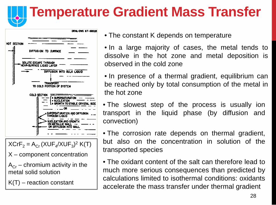
Temperature Gradient Mass Transfer
XCrF2 = ACr (XUF4/XUF3)2 K(T)
X – component concentration
ACr – chromium activity in the metal solid solution
K(T) – reaction constant
• The constant K depends on temperature
• In a large majority of cases, the metal tends to dissolve in the hot zone and metal deposition is observed in the cold zone
• In presence of a thermal gradient, equilibrium can be reached only by total consumption of the metal in the hot zone
• The slowest step of the process is usually ion transport in the liquid phase (by diffusion and convection)
• The corrosion rate depends on thermal gradient, but also on the concentration in solution of the transported species
• The oxidant content of the salt can therefore lead to much more serious consequences than predicted by calculations limited to isothermal conditions: oxidants accelerate the mass transfer under thermal gradient
29
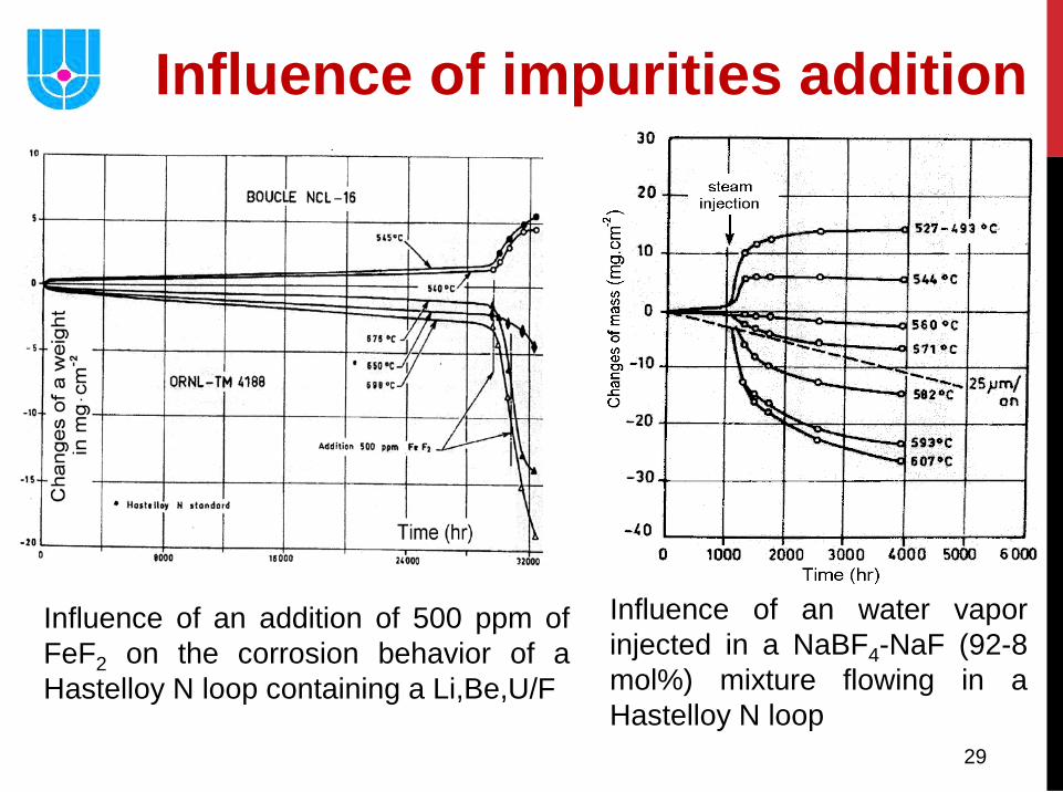
Influence of an addition of 500 ppm of FeF2 on the corrosion behavior of a Hastelloy N loop containing a Li,Be,U/F
Influence of an water vapor injected in a NaBF4-NaF (92-8 mol%) mixture flowing in a Hastelloy N loop
Influence of impurities addition
30
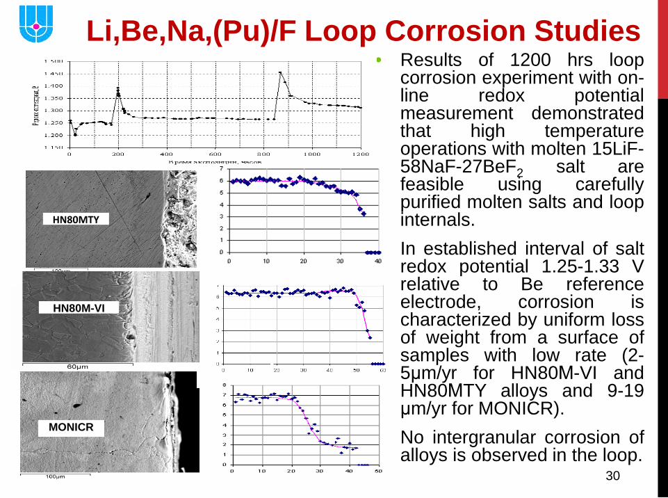
Li,Be,Na,(Pu)/F Loop Corrosion Studies • Results of 1200 hrs loop
corrosion experiment with on-line redox potential measurement demonstrated that high temperature operations with molten 15LiF-58NaF-27BeF2 salt are feasible using carefully purified molten salts and loop internals.
• In established interval of salt redox potential 1.25-1.33 V relative to Be reference electrode, corrosion is characterized by uniform loss of weight from a surface of samples with low rate (2-5μm/yr for HN80М-VI and HN80МTY alloys and 9-19 μm/yr for MONICR).
• No intergranular corrosion of alloys is observed in the loop.
MONICR
μm
HN80MTY
HN80M-VI
Cr, mass.%
31
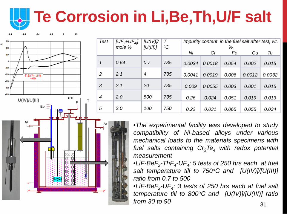
Te Corrosion in Li,Be,Th,U/F salt
•The experimental facility was developed to study compatibility of Ni-based alloys under various mechanical loads to the materials specimens with fuel salts containing Cr3Te4 with redox potential measurement •LiF-BeF2-ThF4-UF4: 5 tests of 250 hrs each at fuel salt temperature till to 750оС and [U(IV)]/[U(III)] ratio from 0.7 to 500 •LiF-BeF2-UF4: 3 tests of 250 hrs each at fuel salt temperature till to 800оС and [U(IV)]/[U(III)] ratio from 30 to 90
F
Ar
T
Ar
Ep
Cr3Te4
Test [UF3+UF4]] mole %
[U(IV)]/ [U(III)]
T oC
Impurity content in the fuel salt after test, wt. %
Ni Cr Fe Cu Te
1 0.64 0.7 735 0.0034 0.0018 0.054 0.002 0.015
2 2.1 4 735 0.0041 0.0019 0.006 0.0012 0.0032
3 2.1 20 735 0.009 0.0055 0.003 0.001 0.015
4 2.0 500 735 0.26 0.024 0.051 0.019 0.013
5 2.0 100 750 0.22 0.031 0.065 0.055 0.034
U(IV)/U(III)
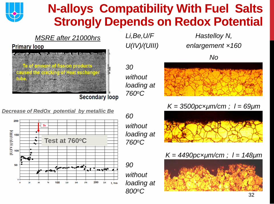
32
Li,Be,U/F U(IV)/(UIII)
Hastelloy N, enlargement ×160
30 without loading at 760oC
No
60 without loading at 760oC
K = 3500pc×μm/cm ; l = 69μm
90 without loading at 800oC
K = 4490pc×μm/cm ; l = 148μm
Test at 760oC
Decrease of RedOx potential by metallic Be
N-alloys Compatibility With Fuel Salts Strongly Depends on Redox Potential
MSRE after 21000hrs
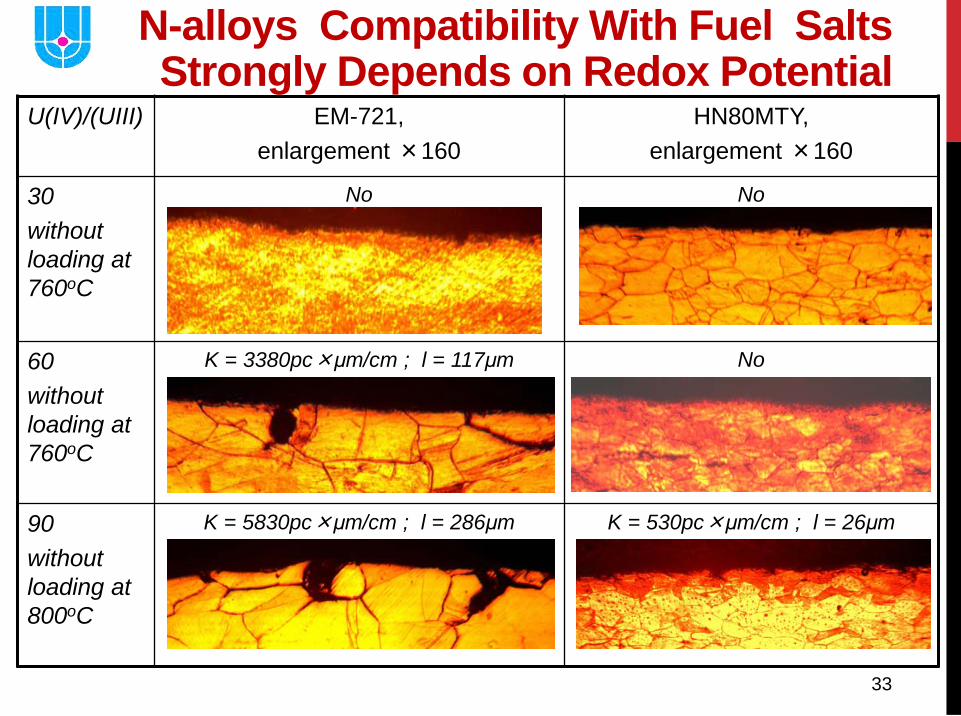
33
U(IV)/(UIII) EM-721, enlargement ×160
HN80MTY, enlargement ×160
30 without loading at 760oC
No No
60 without loading at 760oC
K = 3380pc×μm/cm ; l = 117μm
No
90 without loading at 800oC
K = 5830pc×μm/cm ; l = 286μm
K = 530pc×μm/cm ; l = 26μm
N-alloys Compatibility With Fuel Salts Strongly Depends on Redox Potential
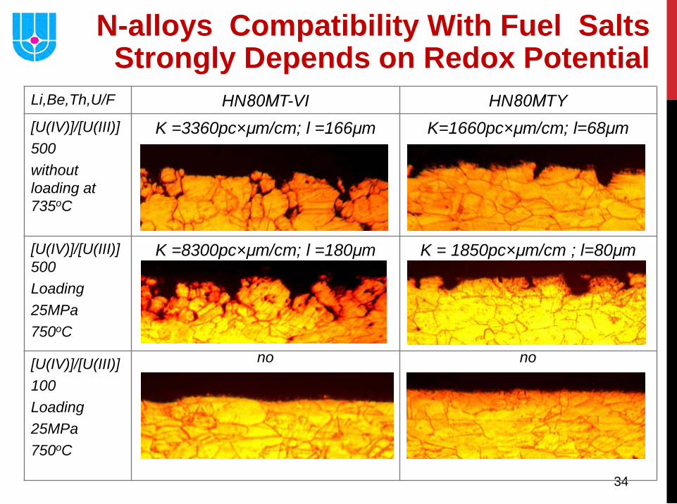
34
Li,Be,Th,U/F HN80МT-VI HN80МTY [U(IV)]/[U(III)] 500 without loading at 735oC
K =3360pc×μm/cm; l =166μm K=1660pc×μm/cm; l=68μm
[U(IV)]/[U(III)]500 Loading 25MPa 750oC
K =8300pc×μm/cm; l =180μm K = 1850pc×μm/cm ; l=80μm
[U(IV)]/[U(III)] 100 Loading 25MPa 750oC
no no
N-alloys Compatibility With Fuel Salts Strongly Depends on Redox Potential
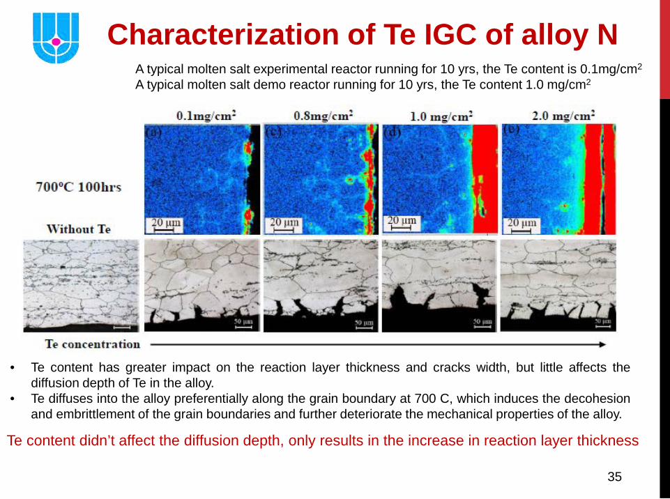
35
Characterization of Te IGC of alloy N A typical molten salt experimental reactor running for 10 yrs, the Te content is 0.1mg/cm2 A typical molten salt demo reactor running for 10 yrs, the Te content 1.0 mg/cm2
• Te content has greater impact on the reaction layer thickness and cracks width, but little affects the diffusion depth of Te in the alloy.
• Te diffuses into the alloy preferentially along the grain boundary at 700 C, which induces the decohesion and embrittlement of the grain boundaries and further deteriorate the mechanical properties of the alloy.
Te content didn’t affect the diffusion depth, only results in the increase in reaction layer thickness
36
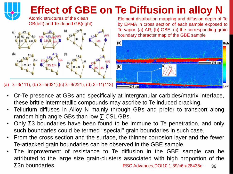
• Cr-Te presence at GBs and specifically at intergranular carbides/matrix interface, these brittle intermetallic compounds may ascribe to Te induced cracking.
• Tellurium diffuses in Alloy N mainly through GBs and prefer to transport along random high angle GBs than low ∑ CSL GBs.
• Only Σ3 boundaries have been found to be immune to Te penetration, and only such boundaries could be termed ‘‘special’’ grain boundaries in such case.
• From the cross section and the surface, the thinner corrosion layer and the fewer Te-attacked grain boundaries can be observed in the GBE sample.
• The improvement of resistance to Te diffusion in the GBE sample can be attributed to the large size grain-clusters associated with high proportion of the Σ3n boundaries. RSC Advances,DOI10.1.39/c6ra28435c
Effect of GBE on Te Diffusion in alloy N Element distribution mapping and diffusion depth of Te by EPMA in cross section of each sample exposed to Te vapor. (a) AR; (b) GBE; (c) the corresponding grain boundary character map of the GBE sample
(a) Σ=3(111), (b) Σ=5(021),(c) Σ=9(221), (d) Σ=11(113)
Atomic structures of the clean GB(left) and Te-doped GB(right)
37
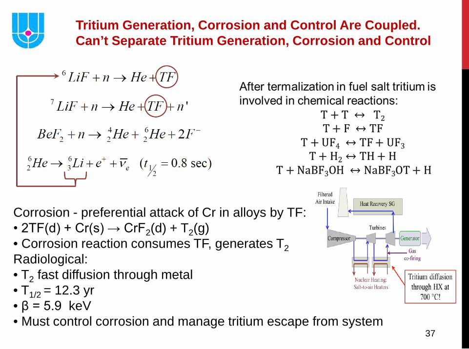
Tritium Generation, Corrosion and Control Are Coupled. Can’t Separate Tritium Generation, Corrosion and Control
Corrosion - preferential attack of Cr in alloys by TF: • 2TF(d) + Cr(s) → CrF2(d) + T2(g) • Corrosion reaction consumes TF, generates T2 Radiological: • T2 fast diffusion through metal • T1/2 = 12.3 yr • β = 5.9 keV • Must control corrosion and manage tritium escape from system
38
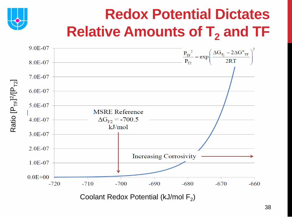
Redox Potential Dictates Relative Amounts of T2 and TF
Rat
io [P
TF]2 /
[PT2
]
Coolant Redox Potential (kJ/mol F2)
39
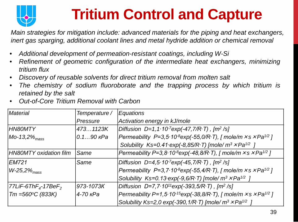
Material Temperature / Pressure
Equations Activation energy in kJ/mole
HN80MTY Mo-13,2%mass
473…1123K 0.1…90 кPа
Diffusion D=1,1∙10-7exp(-47,7/R∙T) , [m2 /s] Permeability P=3,5∙10-8exp(-55,0/R∙T), [ mole/m×s×Pa1/2 ] Solubility Ks=0.41∙exp(-8,85/R∙T) [mole/ m3×Pa1/2 ]
HN80MTY oxidation film Same Permeability P=3,8∙10-8exp(-48,8/R∙T), [ mole/m×s×Pa1/2 ] ЕМ721 W-25,2%mass
Same Diffusion D=4,5∙10-7exp(-45,7/R∙T) , [m2 /s] Permeability P=3,7∙10-8exp(-55,4/R∙T), [ mole/m×s×Pa1/2 ] Solubility Ks=0.13∙exp(-9,6/R∙T) [mole/ m3×Pa1/2 ]
77LiF-6ThF4-17BeF2 Тm =560oC (833K)
973-1073К 4-70 кPа
Diffusion D=7,7∙1011exp(-393,5/R∙T) , [m2 /s] Permeability P=1,5∙10-15exp(-38,8/R∙T), [ mole/m×s×Pa1/2 ] Solubility Ks=2,0 exp(-390,1/R∙T) [mole/ m3×Pa1/2 ]
Tritium Control and Capture Main strategies for mitigation include: advanced materials for the piping and heat exchangers, inert gas sparging, additional coolant lines and metal hydride addition or chemical removal
• Additional development of permeation-resistant coatings, including W-Si • Refinement of geometric configuration of the intermediate heat exchangers, minimizing
tritium flux • Discovery of reusable solvents for direct tritium removal from molten salt • The chemistry of sodium fluoroborate and the trapping process by which tritium is
retained by the salt • Out-of-Core Tritium Removal with Carbon
40
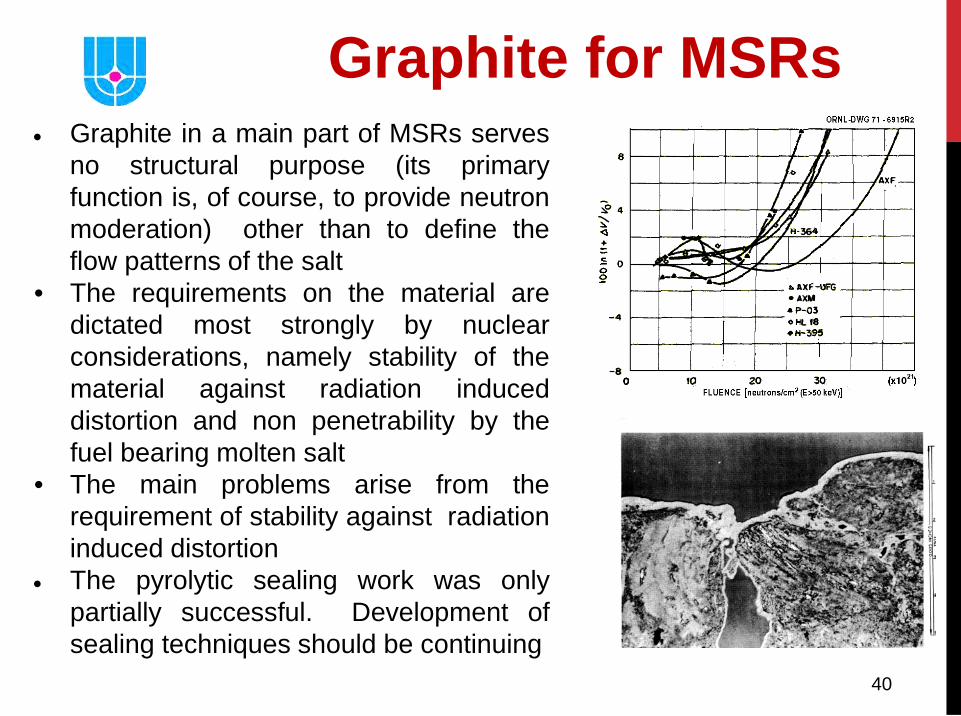
• Graphite in a main part of MSRs serves no structural purpose (its primary function is, of course, to provide neutron moderation) other than to define the flow patterns of the salt
• The requirements on the material are dictated most strongly by nuclear considerations, namely stability of the material against radiation induced distortion and non penetrability by the fuel bearing molten salt
• The main problems arise from the requirement of stability against radiation induced distortion
• The pyrolytic sealing work was only partially successful. Development of sealing techniques should be continuing
Graphite for MSRs
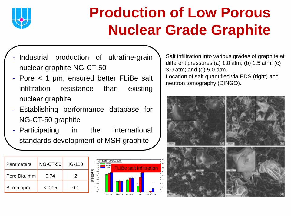
- Industrial production of ultrafine-grain nuclear graphite NG-CT-50
- Pore < 1 μm, ensured better FLiBe salt infiltration resistance than existing nuclear graphite
- Establishing performance database for NG-CT-50 graphite
- Participating in the international standards development of MSR graphite
Parameters NG-CT-50 IG-110
Pore Dia. mm 0.74 2
Boron ppm < 0.05 0.1 0
2
4
6
8
10
12
14
16
0
2
4
6
8
10
12
14
16
燃料球基体石墨
PB
6atm 8atm 10atm
NG-CT-50NG-CT-10NBG-18
浸
渗量
(wt.%
)
FLiBe--700oC, 20h
IG-110
Production of Low Porous Nuclear Grade Graphite
Salt infiltration into various grades of graphite at different pressures (a) 1.0 atm; (b) 1.5 atm; (c) 3.0 atm; and (d) 5.0 atm. Location of salt quantified via EDS (right) and neutron tomography (DINGO).
FLiBe salt infiltration
42
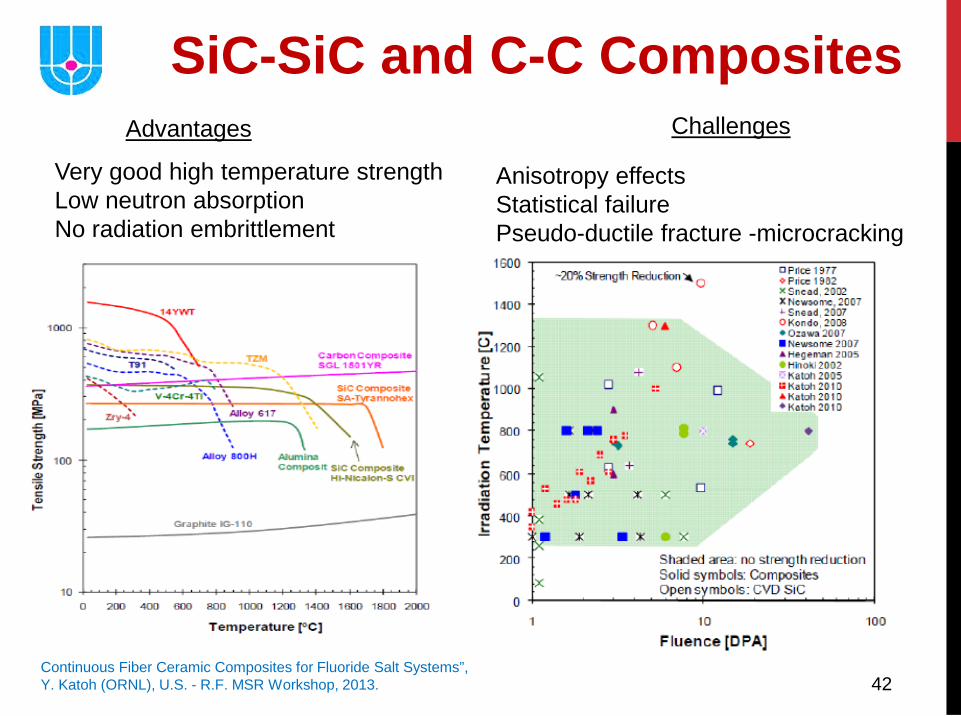
SiC-SiC and C-C Composites Advantages
Very good high temperature strength Low neutron absorption No radiation embrittlement
Anisotropy effects Statistical failure Pseudo-ductile fracture -microcracking
Continuous Fiber Ceramic Composites for Fluoride Salt Systems”, Y. Katoh (ORNL), U.S. - R.F. MSR Workshop, 2013.
Challenges
43
SiC-based materials have potential application in MSR due to its’ low neutron-induced radioactivity, excellent irradiation tolerance, inherently low activation / low decay heat, and superior physical / chemical properties.
• The corrosion of CVD SiC, pressureless sintering SiC ceramic, SiC fiber and SiCf/SiC composite in molten FLiNaK salt were studied.
• Results reveal that oxygen impurity in FLiNaK salt and SiC-based materials can both induce the corrosion.
• Hastelloy N alloy and its corrosion products can also affect the corrosion of SiC-based materials in molten FLiNaK salt.
• Ni in alloy can react with the corrosion product of SiC in salt to form nickel silicides (NiSi, Ni31Si12).
• NiF2, the corrosion product of Ni, can result in the dissolution of SiC into salt as in the form of [SiF6]2-. CrF2 and CrF3, the corrosion products of Cr, can react with SiC to form chromium carbides (CrC, Cr3C2, Cr7C3)
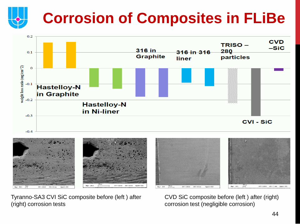
44
Corrosion of Composites in FLiBe
CVD SiC composite before (left ) after (right) corrosion test (negligible corrosion)
Tyranno-SA3 CVI SiC composite before (left ) after (right) corrosion tests

45
• The materials requirements for MSR fuel processing systems are dependent upon the processing methods utilized and the design of particular equipment items selected for effecting these processing steps. Processes involving removal of uranium from fuel salt by fluorination and selective extraction of Pa and FPs products from fuel salt into liquid bismuth are considered the most promising method available, and the current processing materials studies is oriented in this direction.
• It is not necessary that a single material be compatible with all environments anticipated in the processing plant since the system can be designed to allow segregation of particular portions of the plant. It is expected that at least two classes of materials will be required: one for the fluorination and fuel reconstitution steps and another for the reductive extraction steps.
• Ni, which in some cases must be protected from corrosion by a layer of frozen salt, can be used for construction of fluorinators, and for those portions of a plant which contain fluorine, UF6 and HF.
• Materials which have shown good compatibility with Bi solutions during limited tests include graphite and refractory metals such as tungsten, rhenium, molybdenum, and tantalum. Except for Ta, these materials are difficult to fabricate and join.
Fuel Processing Materials Development
46
• Experience with the MSRE has proven the basic compatibility of the “graphite - Hastelloy-N - fluoride salt” system at elevated temperatures. However, а MOSART and MSFR will impose more stringent operating conditions, and some improvements in the Ni based alloy and probably graphite for this systems are needed.
• The mechanical properties of Hastelloy-N deteriorate under thermal-neutron irradiation, but the addition of titanium in combination with strong carbide formers such as niobium and hafnium makes the alloy more resistant to this type of irradiation damage.
• Graphite undergoes dimensional changes due to exposure to fast neutrons, and the possible loss of structural integrity due to these dimensional changes presently limits the lifetime of the reflector graphite. Studies to date indicate that graphite can be developed that have better resistance to irradiation damage than conventional nuclear graphites. The graphite used in the core will be sealed with pyrocarbon to reduce the amount of Хе that is absorbed. Techniques have been developed for this sealing, and studies are in progress to determine whether the low permeability is retained after irradiation.
• Corrosion studies indicate that the corrosion rate of Hastelloy-N in sodium fluoroborate is ассерtаblе as long as the salt does not contain large amounts of impurities, such as HF and Н2О.
Summary