Embed Size (px)
Citation preview
1
"Historical MSR programme in Russia"
Presented by Victor Ignatiev National Research Center “Kurchatov
Institute”
123182, Kurchatov sq., 1, Moscow, Russia [email protected]
MSR Summer school, July 2-4, 2017, Lecco, Italy
2
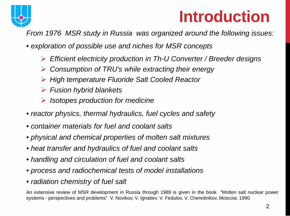
Introduction From 1976 MSR study in Russia was organized around the following issues:
• exploration of possible use and niches for MSR concepts
Efficient electricity production in Th-U Converter / Breeder designs Consumption of TRU’s while extracting their energy High temperature Fluoride Salt Cooled Reactor Fusion hybrid blankets Isotopes production for medicine
• reactor physics, thermal hydraulics, fuel cycles and safety
• container materials for fuel and coolant salts • physical and chemical properties of molten salt mixtures • heat transfer and hydraulics of fuel and coolant salts • handling and circulation of fuel and coolant salts • process and radiochemical tests of model installations • radiation chemistry of fuel salt An extensive review of MSR development in Russia through 1989 is given in the book “Molten salt nuclear power systems - perspectives and problems” V. Novikov, V. Ignatiev, V. Fedulov, V. Cherednikov, Moscow, 1990
3
Today different fast reactor concepts using molten salt are under consideration in Russia
• R&D studies are on-going in order to verify that fast spectrum MSR systems satisfy the goals of Gen-IV in terms of technical feasibility, sustainability, non-proliferation, safety and waste management
• MOSART studies are done within ISTC#1606 and #3749 tasks as well as Rosatom MARS and Euratom FP6 EVOL projects
• Kurchatov Institute is a partner for EU Horizon 2020 SAMOFAR project focused on MSFR safety
• Today Kurchatov Institute supports some experimental studies concerning fuel salt & material properties for MOSART
• Other groups are still interested to consider concepts of the Li,Na,K/F MSFR operating in U-Pu fuel cycle with a very low technology readiness levels
4
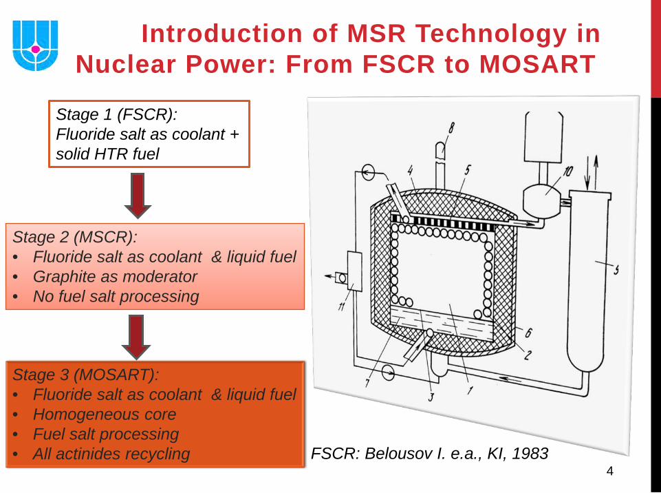
Introduction of MSR Technology in Nuclear Power: From FSCR to MOSART
Stage 1 (FSCR): Fluoride salt as coolant + solid HTR fuel
Stage 2 (MSCR): • Fluoride salt as coolant & liquid fuel • Graphite as moderator • No fuel salt processing
FSCR: Belousov I. e.a., KI, 1983
Stage 3 (MOSART): • Fluoride salt as coolant & liquid fuel • Homogeneous core • Fuel salt processing • All actinides recycling
5
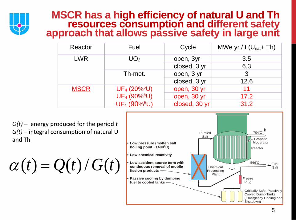
Reactor Fuel Cycle MWe yr / t (Unat+ Th)
LWR UO2 open, 3yr 3.5 closed, 3 yr 6.3
Th-met. open, 3 yr 3 closed, 3 yr 12.6
MSCR UF4 (20%5U) UF4 (90%5U) UF4 (90%5U)
open, 30 yr 11 open, 30 yr 17.2 closed, 30 yr 31.2
)(/)()( tGtQt =αReactor
GraphiteModerator
PurifiedSalt
ChemicalProcessing
PlantFreeze
Plug
Critically Safe, PassivelyCooled Dump Tanks(Emergency Cooling andShutdown)
Low accident source term withcontinuous removal of mobilefission products
Low pressure (molten saltboiling point ~1400 C)o
Low chemical reactivity
Passive cooling by dumpingfuel to cooled tanks
FuelSalt
566 Co
704 Co
MSCR has a high efficiency of natural U and Th resources consumption and different safety
approach that allows passive safety in large unit
Q(t) – energy produced for the period t G(t) – integral consumption of natural U and Th
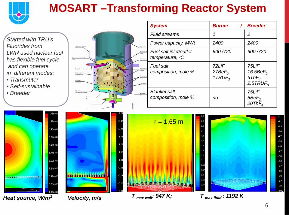
6 Heat source, W/m3 T max wall: 947 K; T max fluid : 1192 K Velocity, m/s
r = 1,65 m
Started with TRU’s Fluorides from LWR used nuclear fuel has flexible fuel cycle and can operate in different modes: • Transmuter • Self-sustainable • Breeder
MOSART –Transforming Reactor System System Burner / Breeder
Fluid streams 1 2
Power capacity, MWt 2400 2400
Fuel salt inlet/outlet temperature, oC
600 /720 600 /720
Fuel salt composition, mole %
72LiF 27BeF2 1TRUF3
75LiF 16.5BeF2 6ThF4 2.5TRUF3
Blanket salt composition, mole %
no
75LiF 5BeF2 20ThF4
7
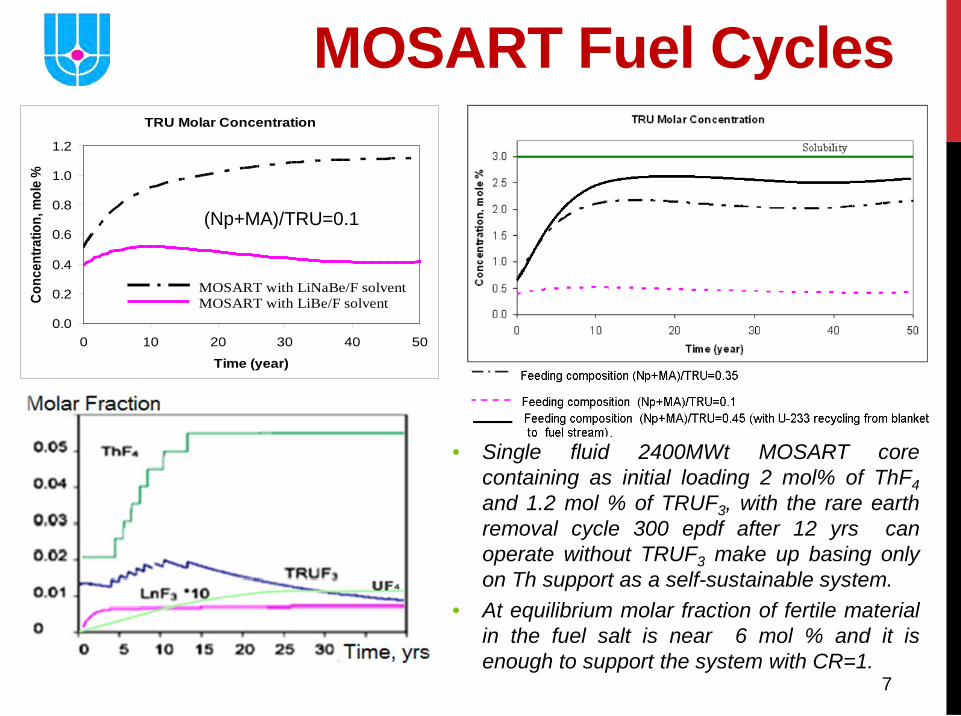
MOSART Fuel Cycles
• Single fluid 2400MWt MOSART core containing as initial loading 2 mol% of ThF4 and 1.2 mol % of TRUF3, with the rare earth removal cycle 300 epdf after 12 yrs can operate without TRUF3 make up basing only on Th support as a self-sustainable system.
• At equilibrium molar fraction of fertile material in the fuel salt is near 6 mol % and it is enough to support the system with CR=1.
TRU Molar Concentration
0.0
0.2
0.4
0.6
0.8
1.0
1.2
0 10 20 30 40 50
Time (year)
Conc
entra
tion,
mol
e %
MOSART with LiNaBe/F solvent MOSART with LiBe/F solvent
(Np+MA)/TRU=0.1
8
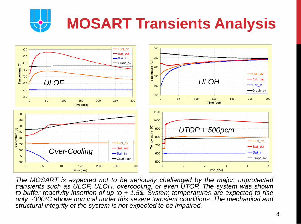
The MOSART is expected not to be seriously challenged by the major, unprotected transients such as ULOF, ULOH, overcooling, or even UTOP. The system was shown to buffer reactivity insertion of up to + 1.5$. System temperatures are expected to rise only ~300oC above nominal under this severe transient conditions. The mechanical and structural integrity of the system is not expected to be impaired.
550
600
650
700
750
800
850
900
0 50 100 150 200 250 300Time [sec]
Tem
pera
ture
[C
]
Fuel_avSalt_outSalt_inGraph_av
ULOF 550
600
650
700
750
800
0 50 100 150 200 250 300Time [sec]
Tem
pera
ture
[C]
Fuel_av
Salt_out
Salt_in
Graph_av
ULOH
500
550
600
650
700
750
800
850
900
0 50 100 150 200 250 300
Time [sec]
Tem
pera
ture
[C]
Fuel_av
Salt_out
Salt_in
Graph_av
Over-Cooling 500
600
700
800
900
1000
1100
0 1 2 3 4 5Time [sec]
Tem
pera
ture
[C
]
Fuel_av
Salt_out
Salt_in
Graph_av
UTOP + 500pcm
MOSART Transients Analysis
9
Reactor compartment Containment
Processing unit
Reactor cell
Auxiliary compartment
Fuel salt storage
Cooling system
Drain tank
Intermediate circuit
Pump Reactor vessel
Fuel catcher
Freeze valve
Drain tank
Cooling system
Accidental drain reservoir
Water
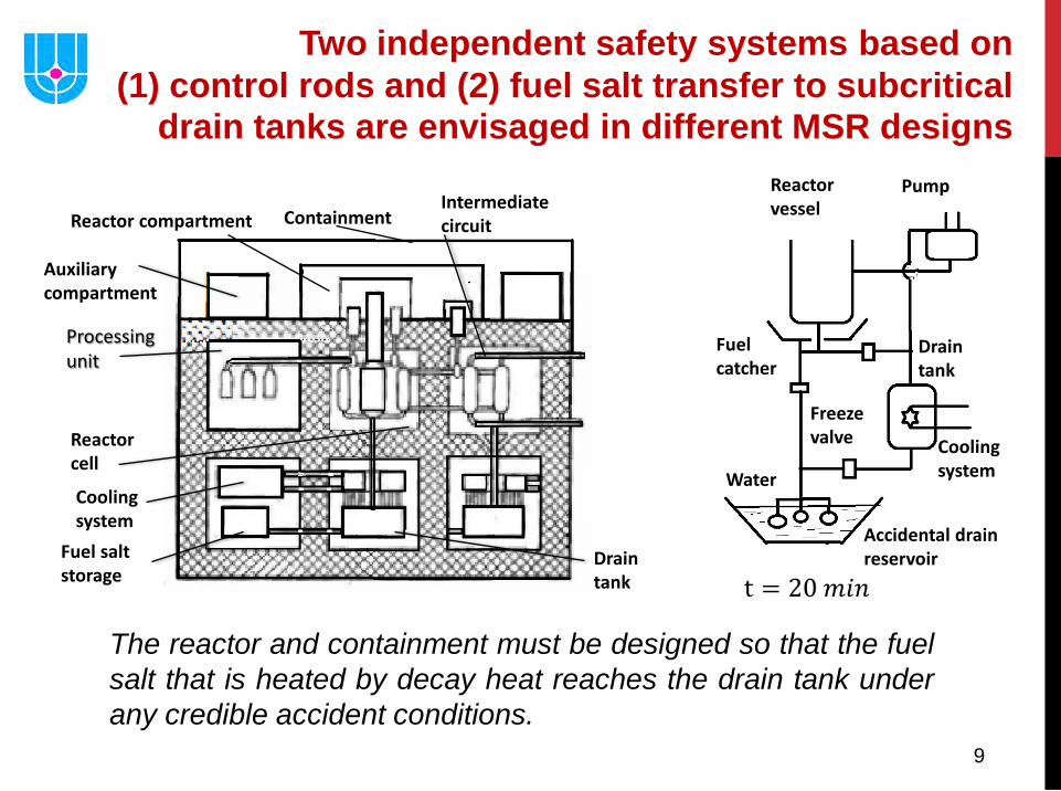
Two independent safety systems based on (1) control rods and (2) fuel salt transfer to subcritical
drain tanks are envisaged in different MSR designs
The reactor and containment must be designed so that the fuel salt that is heated by decay heat reaches the drain tank under any credible accident conditions.
10
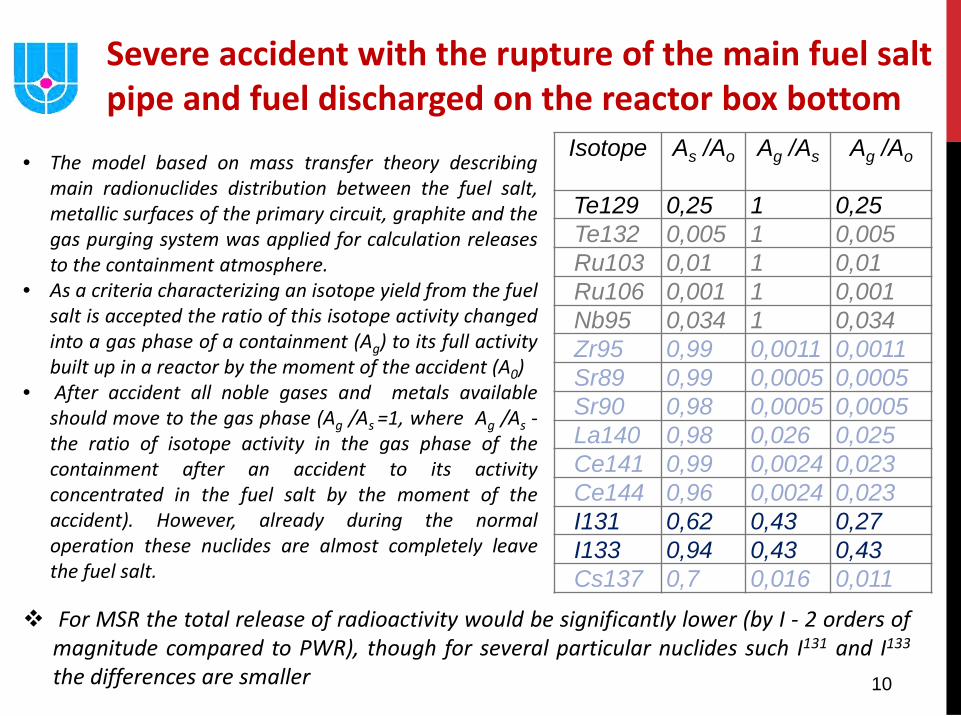
Isotope As /Ao Ag /As Ag /Ao
Te129 0,25 1 0,25 Te132 0,005 1 0,005 Ru103 0,01 1 0,01 Ru106 0,001 1 0,001 Nb95 0,034 1 0,034 Zr95 0,99 0,0011 0,0011 Sr89 0,99 0,0005 0,0005 Sr90 0,98 0,0005 0,0005 La140 0,98 0,026 0,025 Ce141 0,99 0,0024 0,023 Ce144 0,96 0,0024 0,023 I131 0,62 0,43 0,27 I133 0,94 0,43 0,43 Cs137 0,7 0,016 0,011
Severe accident with the rupture of the main fuel salt pipe and fuel discharged on the reactor box bottom
• The model based on mass transfer theory describing main radionuclides distribution between the fuel salt, metallic surfaces of the primary circuit, graphite and the gas purging system was applied for calculation releases to the containment atmosphere.
• As a criteria characterizing an isotope yield from the fuel salt is accepted the ratio of this isotope activity changed into a gas phase of a containment (Ag) to its full activity built up in a reactor by the moment of the accident (A0)
• After accident all noble gases and metals available should move to the gas phase (Ag /As =1, where Ag /As -the ratio of isotope activity in the gas phase of the containment after an accident to its activity concentrated in the fuel salt by the moment of the accident). However, already during the normal operation these nuclides are almost completely leave the fuel salt.
For MSR the total release of radioactivity would be significantly lower (by I - 2 orders of magnitude compared to PWR), though for several particular nuclides such I131 and I133 the differences are smaller
11
Acci
dent
al F
requ
ency
Consequences of Accidents
MSR
LWR
Taube M., Fast and thermal molten salt reactors with improved inherent safety // TANS, 1981, Summer meeting, pp. 490-498
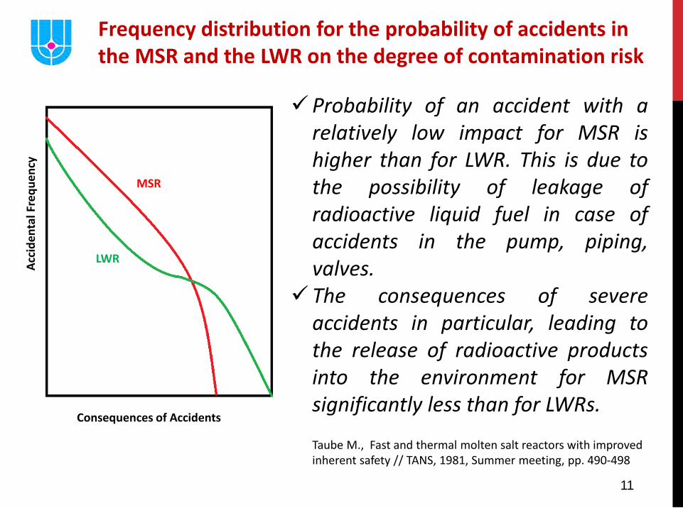
Probability of an accident with a relatively low impact for MSR is higher than for LWR. This is due to the possibility of leakage of radioactive liquid fuel in case of accidents in the pump, piping, valves.
The consequences of severe accidents in particular, leading to the release of radioactive products into the environment for MSR significantly less than for LWRs.
Frequency distribution for the probability of accidents in the MSR and the LWR on the degree of contamination risk
12
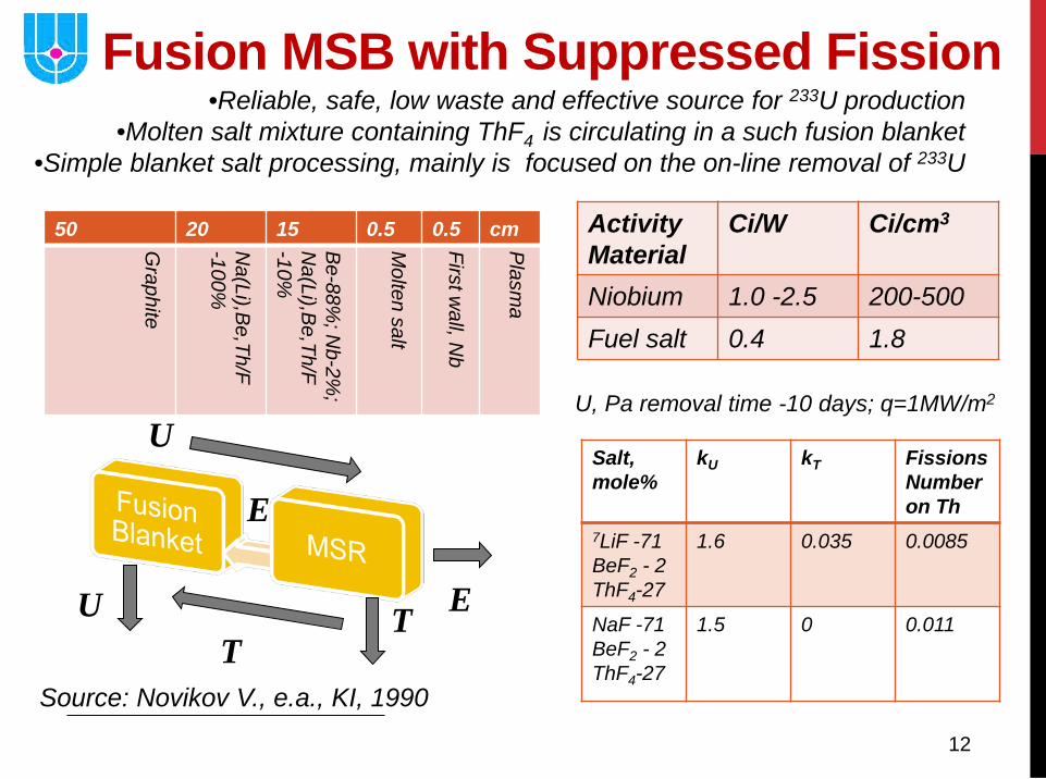
Fusion MSB with Suppressed Fission
Salt, mole%
kU kT Fissions Number on Th
7LiF -71 BeF2 - 2 ThF4-27
1.6 0.035 0.0085
NaF -71 BeF2 - 2 ThF4-27
1.5 0 0.011
50 20 15 0.5 0.5 cm
Graphite
Na(Li),B
e,Th/F -100%
Be-88%
; Nb-2%
; N
a(Li),Be,Th/F
-10%
Molten salt
First wall, N
b
Plasm
a
Activity Material
Ci/W Ci/cm3
Niobium 1.0 -2.5 200-500 Fuel salt 0.4 1.8
U, Pa removal time -10 days; q=1MW/m2 U
E
T E U T
Source: Novikov V., e.a., KI, 1990
•Reliable, safe, low waste and effective source for 233U production •Molten salt mixture containing ThF4 is circulating in a such fusion blanket
•Simple blanket salt processing, mainly is focused on the on-line removal of 233U
13
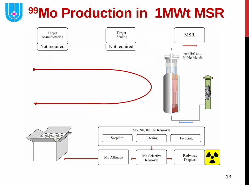
99Мo Production in 1MWt MSR
14
LiF
BeF2
LnF3
AnF3
AnF4 Fuel salt
Actinide solubility
Viscosity
Density
Thermal conductivity
Heat capacity
Melting temperature
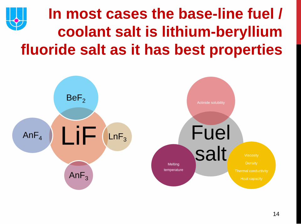
In most cases the base-line fuel / coolant salt is lithium-beryllium
fluoride salt as it has best properties
15
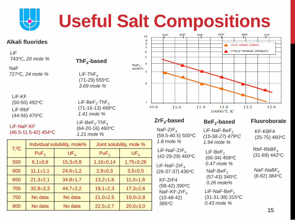
Useful Salt Compositions Alkali fluorides
ThF4-based
ZrF4-based
BeF2-based
Fluoroborate
LiF 743oC, 20 mole %
NaF 727oC, 24 mole %
LiF-ThF4 (71-29) 555oC 3.69 mole %
LiF-KF (50-50) 492oC
LiF-BeF2-ThF4 (71-16-13) 499oC 1.41 mole %
NaF-ZrF4 (59.5-40.5) 500oC 1.8 mole %
LiF-NaF-BeF2 (15-58-27) 479oC 1.94 mole %
LiF-RbF (44-56) 470oC
LiF-NaF-KF (46.5-11.5-42) 454oC
LiF-BeF2-ThF4 (64-20-16) 460oC 1.21 mole %
LiF-NaF-ZrF4 (42-29-29) 460oC
LiF-BeF2 (66-34) 458oC 0.47 mole %
KF-KBF4 (25-75) 460oC
LiF-NaF-ZrF4 (26-37-37) 436oC
RbF-RbBF4 (31-69) 442oC
KF-ZrF4 (58-42) 390oC NaF-KF-ZrF4 (10-48-42) 385oC
NaF-NaBF4
(8-92) 384oC
NaF-BeF2 (57-43) 340oC 0.26 mole%
LiF-NaF-BeF2 (31-31-38) 315oC 0.43 mole %
T,0С Indvidual solubility, mole% Joint solubility, mole %
PuF3 UF4 PuF3 UF4
550 6,1±0,6 15,3±0,8 1,16±0,14 1,75±0,26
600 11,1±1,1 24,6±1,2 2,9±0,3 3,5±0,5
650 21,3±2,1 34,8±1,7 13,2±1,6 11,0±1,6
700 32,8±3,3 44,7±2,2 19,1±2,3 17,3±2,6
750 No data No data 21,0±2,5 19,0±2,8
800 No data No data 22,5±2,7 20,0±3,0
16
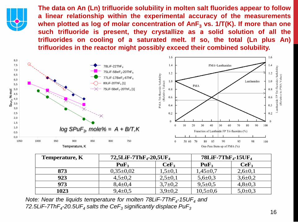
The data on An (Ln) trifluoride solubility in molten salt fluorides appear to follow a linear relationship within the experimental accuracy of the measurements when plotted as log of molar concentration of AnF3 vs. 1/T(K). If more than one such trifluoride is present, they crystallize as а solid solution of all the trifluorides on cooling of а saturated melt. If so, the total (Ln plus An) trifluorides in the reactor might possibly exceed their combined solubility.
0,0
0,5
1,0
1,5
2,0
2,5
3,0
3,5
4,0
4,5
5,0
5,5
6,0
6,5
7,0
7,5
8,0
75080085090095010001050
Temperature, K
S PuF
3, %
mol
77LiF-17BeF2-6ThF4
75LiF-5BeF2-20ThF4
78LiF-22ThF4
80LiF-20ThF4 [1]
75LiF-5BeF2-20ThF4 [1]
log SPuF3, mole% = A + B/T,K
Temperature, K 72,5LiF-7ThF4-20,5UF4 78LiF-7ThF4-15UF4 PuF3 CeF3 PuF3 CeF3
873 0,35±0,02 1,5±0,1 1,45±0,7 2,6±0,1 923 4,5±0,2 2,5±0,1 5,6±0,3 3,6±0,2 973 8,4±0,4 3,7±0,2 9,5±0,5 4,8±0,3 1023 9,4±0,5 3,9±0,2 10,5±0,6 5,0±0,3
Note: Near the liquids temperature for molten 78LiF-7ThF4-15UF4 and 72.5LiF-7ThF4-20.5UF4 salts the CeF3 significantly displace PuF3
17
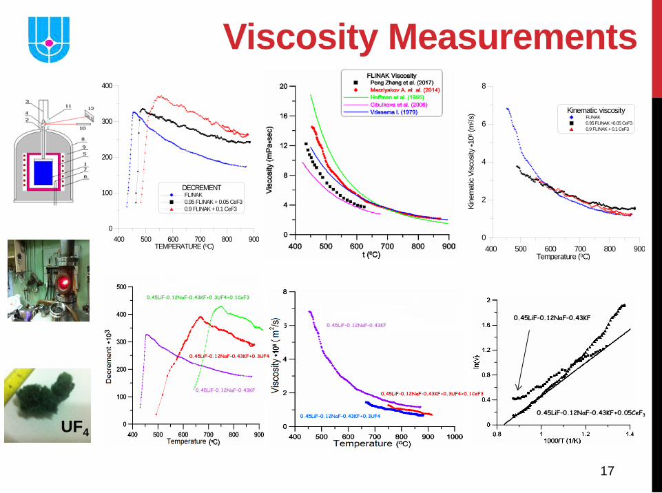
Viscosity Measurements
0.45LiF–0.12NaF–0.43KF+0.3UF4
0.45LiF–0.12NaF–0.43KF
0.45LiF–0.12NaF–0.43KF+0.3UF4+0.1CeF3
0.45LiF–0.12NaF–0.43KF
0.45LiF–0.12NaF–0.43KF+0.3UF4
0.45LiF–0.12NaF–0.43KF+0.3UF4+0.1CeF3
0.45LiF–0.12NaF–0.43KF+0.05CeF3
0.45LiF–0.12NaF–0.43KF
DECREMENTFLINAK0.95 FLINAK + 0.05 CeF30.9 FLINAK + 0.1 CeF3
400 500 600 700 800 900TEMPERATURE (0C)
0
100
200
300
400DE
CREM
ENT *
103
400 500 600 700 800 900Temperature (0C)
0
2
4
6
8
Kine
mat
ic Vi
scos
ity *1
06 (m
2 /s) Kinematic viscosity
FLINAK0.95 FLINAK +0.05 CeF30.9 FLINAK + 0.1 CeF3
UF4
18
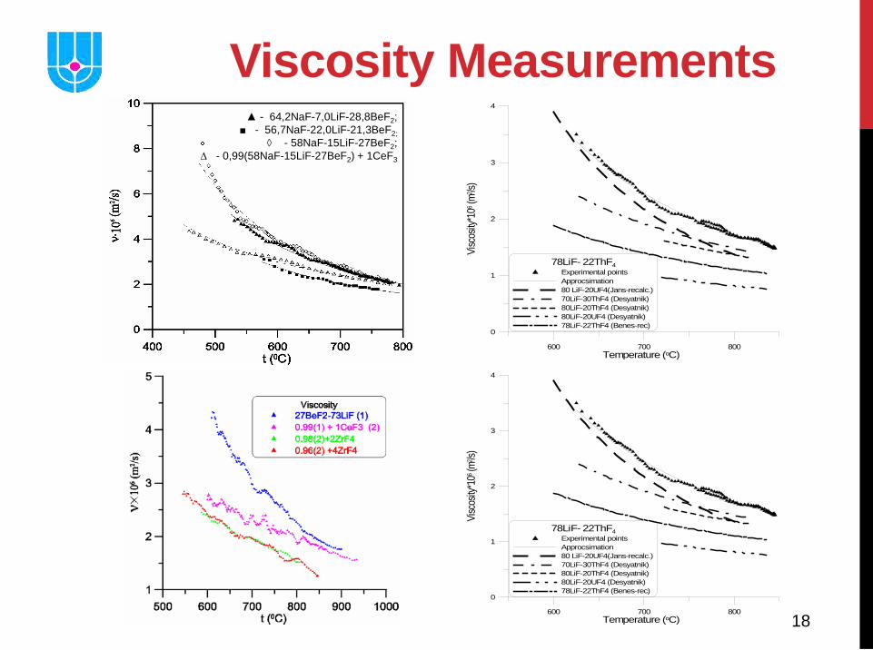
▲ - 64,2NaF-7,0LiF-28,8BeF2; ■ - 56,7NaF-22,0LiF-21,3BeF2;
◊ - 58NaF-15LiF-27BeF2; ∆ - 0,99(58NaF-15LiF-27BeF2) + 1CeF3
600 700 800Temperature (oC)
0
1
2
3
4
Visc
osity
*106 (m
2 /s)
78LiF- 22ThF4Experimental pointsApprocsimation80 LiF-20UF4(Jans-recalc.)70LiF-30ThF4 (Desyatnik)80LiF-20ThF4 (Desyatnik)80LiF-20UF4 (Desyatnik)78LiF-22ThF4 (Benes-rec)
600 700 800Temperature (oC)
0
1
2
3
4
Visc
osity
*106 (m
2 /s)
78LiF- 22ThF4Experimental pointsApprocsimation80 LiF-20UF4(Jans-recalc.)70LiF-30ThF4 (Desyatnik)80LiF-20ThF4 (Desyatnik)80LiF-20UF4 (Desyatnik)78LiF-22ThF4 (Benes-rec)
Viscosity Measurements
19
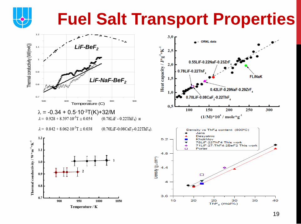
Fuel Salt Transport Properties
500 600 700 800 900Temperature (C)
0.7
0.8
0.9
1
1.1
1.2
Therm
al con
ductiv
ity (W
/(m*K)
)
LiF-BeF2
LiF-NaF-BeF2
λ = -0.34 + 0.5∙10-3Т(K)+32/М
20
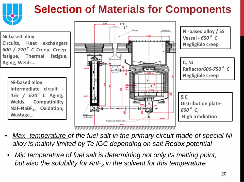
• Max temperature of the fuel salt in the primary circuit made of special Ni- alloy is mainly limited by Te IGC depending on salt Redox potential
Ni-based alloy Circuits, Heat exchangers 600 / 720°C Creep, Creep-fatigue, Thermal fatigue, Aging, Welds…
Ni-based alloy Intermediate circuit - 455 / 620°C Aging, Welds, Compatibility NaF-NaBF4, Oxidation, Wastage…
SiC Distribution plate- 600°C, High irradiation
C, Ni Reflector600-750°C Negligible creep
Ni-based alloy / SS Vessel - 600°C Negligible creep
Selection of Materials for Components
• Min temperature of fuel salt is determining not only its melting point, but also the solubility for AnF3 in the solvent for this temperature
21
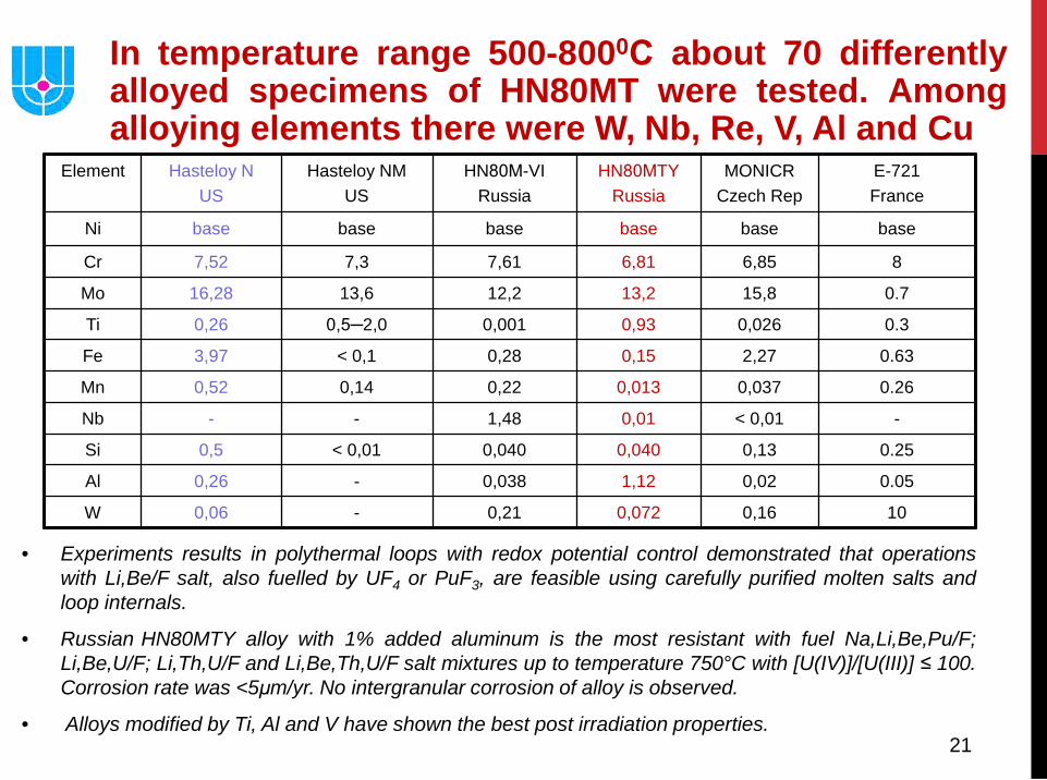
In temperature range 500-8000С about 70 differently alloyed specimens of HN80MT were tested. Among alloying elements there were W, Nb, Re, V, Al and Cu
• Experiments results in polythermal loops with redox potential control demonstrated that operations with Li,Be/F salt, also fuelled by UF4 or PuF3, are feasible using carefully purified molten salts and loop internals.
• Russian HN80MTY alloy with 1% added aluminum is the most resistant with fuel Na,Li,Be,Pu/F; Li,Be,U/F; Li,Th,U/F and Li,Be,Th,U/F salt mixtures up to temperature 750°C with [U(IV)]/[U(III)] ≤ 100. Corrosion rate was <5μm/yr. No intergranular corrosion of alloy is observed.
• Alloys modified by Ti, Al and V have shown the best post irradiation properties.
Element Hasteloy N US
Hasteloy NM US
HN80М-VI Russia
HN80МTY Russia
MONICR Czech Rep
E-721 France
Ni base base base base base base
Cr 7,52 7,3 7,61 6,81 6,85 8
Mo 16,28 13,6 12,2 13,2 15,8 0.7
Ti 0,26 0,5─2,0 0,001 0,93 0,026 0.3
Fe 3,97 < 0,1 0,28 0,15 2,27 0.63
Mn 0,52 0,14 0,22 0,013 0,037 0.26
Nb - - 1,48 0,01 < 0,01 -
Si 0,5 < 0,01 0,040 0,040 0,13 0.25
Al 0,26 - 0,038 1,12 0,02 0.05
W 0,06 - 0,21 0,072 0,16 10
22
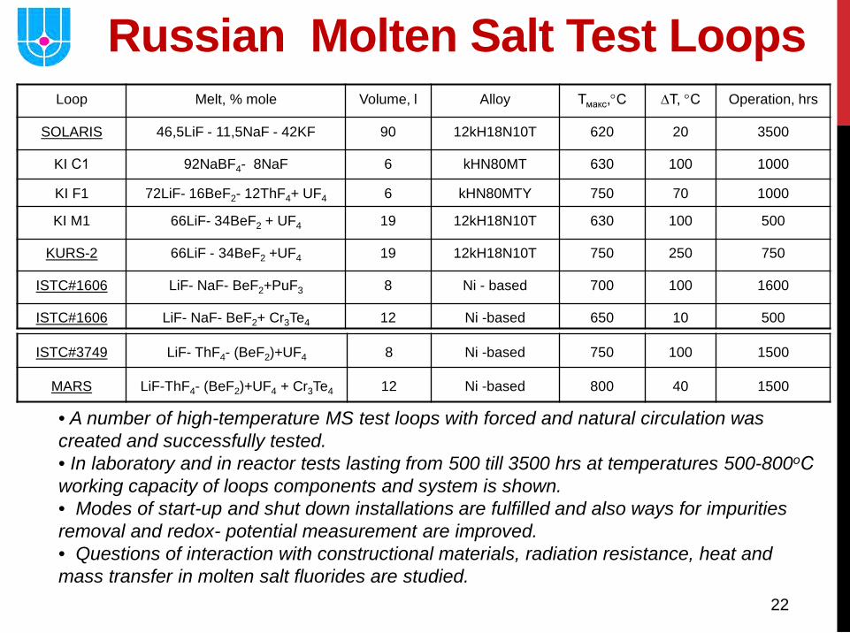
Russian Molten Salt Test Loops
• A number of high-temperature MS test loops with forced and natural circulation was created and successfully tested. • In laboratory and in reactor tests lasting from 500 till 3500 hrs at temperatures 500-800оС working capacity of loops components and system is shown. • Modes of start-up and shut down installations are fulfilled and also ways for impurities removal and redox- potential measurement are improved. • Questions of interaction with constructional materials, radiation resistance, heat and mass transfer in molten salt fluorides are studied.
Loop Melt, % mole Volume, l Alloy Тмакс,°С ∆Т, °С Operation, hrs
SOLARIS 46,5LiF - 11,5NaF - 42KF 90 12kH18N10T 620 20 3500
KI С1 92NaBF4- 8NaF 6 kHN80MT 630 100 1000
KI F1 72LiF- 16BeF2- 12ThF4+ UF4 6 kHN80MTY 750 70 1000
KI M1 66LiF- 34BeF2 + UF4 19 12kH18N10T 630 100 500
KURS-2 66LiF - 34BeF2 +UF4 19 12kH18N10T 750 250 750
ISTC#1606 LiF- NaF- BeF2+PuF3 8 Ni - based 700 100 1600
ISTC#1606 LiF- NaF- BeF2+ Cr3Te4 12 Ni -based 650 10 500
ISTC#3749 LiF- ThF4- (BeF2)+UF4 8 Ni -based 750 100 1500
MARS LiF-ThF4- (BeF2)+UF4 + Cr3Te4 12 Ni -based 800 40 1500
23
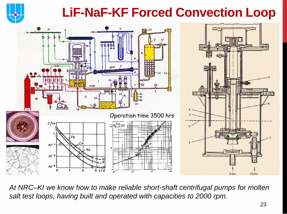
LiF-NaF-KF Forced Convection Loop
Operation time 3500 hrs
At NRC–KI we know how to make reliable short-shaft centrifugal pumps for molten salt test loops, having built and operated with capacities to 2000 rpm.
24
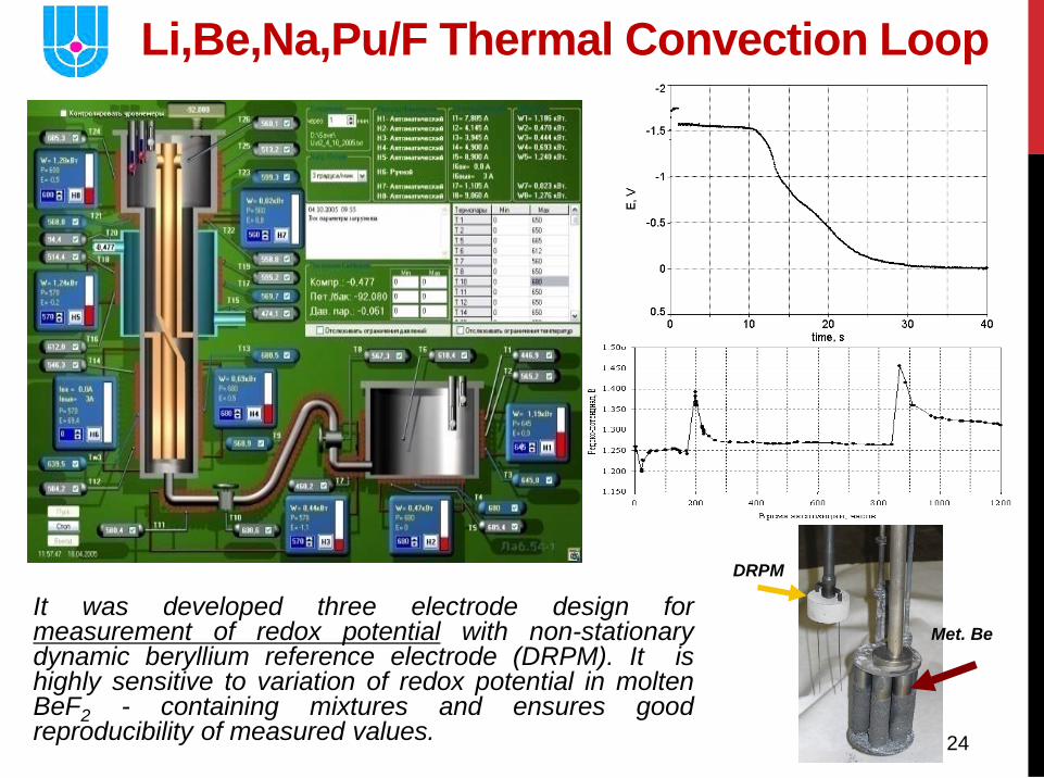
Li,Be,Na,Pu/F Thermal Convection Loop
It was developed three electrode design for measurement of redox potential with non-stationary dynamic beryllium reference electrode (DRPM). It is highly sensitive to variation of redox potential in molten BeF2 - containing mixtures and ensures good reproducibility of measured values.
Met. Be
DRPM

25
KI in reactor tests Fuel salt, mole %
Liquid phase Solid phase T,oC G(F2) ,10-5
mol/100eV T,oC
G(F2),10-2 mol/100eV
66LiF-33BeF2-1UF4 615 7 50 1
69LiF-31BeF2 680 2 0.2
71.7LiF-16BeF2-12ThF4-0.3UF4 740 3 25 0.6
65.67LiF-34.39BeF2-0.3UF4 740 0.2 25 -
73.6iF-25.9.2ThF4-0.5UF4 1200 2 - 2.5
74NaF-25.9ThF4-0.9UF4 1150 0.15 50 2
ORNL tests strongly suggested that the F2 generation had at the high temperature not occurred (gas was generating mainly via reaction 6Li(n,α)T), but had occurred by radiolysis of the mixture in the solid state. F2 evolution at 35°C corresponded to about 0,02 molecules per 100 eV absorbed, could be completely stopped by heating to 100°C or above, and could be reduced by chilling to -70°C. The F2 evolution resumed, usually after a few hours, when temperature was returned to 35 to 50°C.
These and subsequent experiences, including operation of the 8MWe MSRE at US ORNL, strongly indicate that radiolysis of the molten fuel at reasonable power densities is not а problem. It seems unlikely, though it is possible, that MSR fuels will evolve F2 on cooling. If they do, arrangements must be made for their storage at elevated temperature until а fraction of the decay energy is dissipated
26
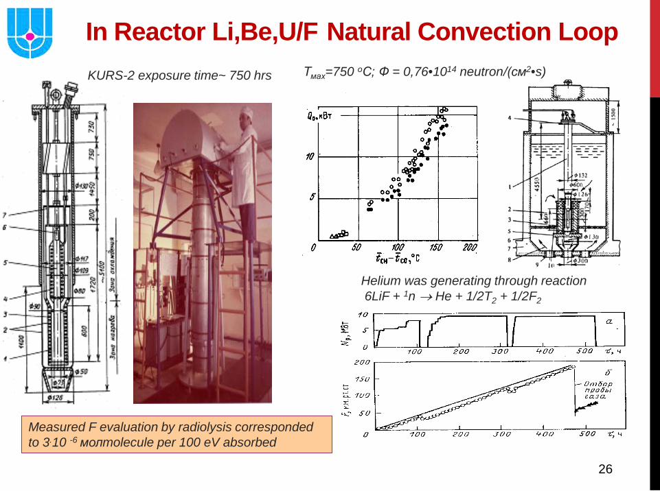
In Reactor Li,Be,U/F Natural Convection Loop
Helium was generating through reaction 6LiF + 1n → He + 1/2T2 + 1/2F2
Measured F evaluation by radiolysis corresponded to 3.10 -6 молmolecule per 100 eV absorbed
Тмах=750 оС; Ф = 0,76•1014 neutron/(см2•s) KURS-2 exposure time~ 750 hrs
27
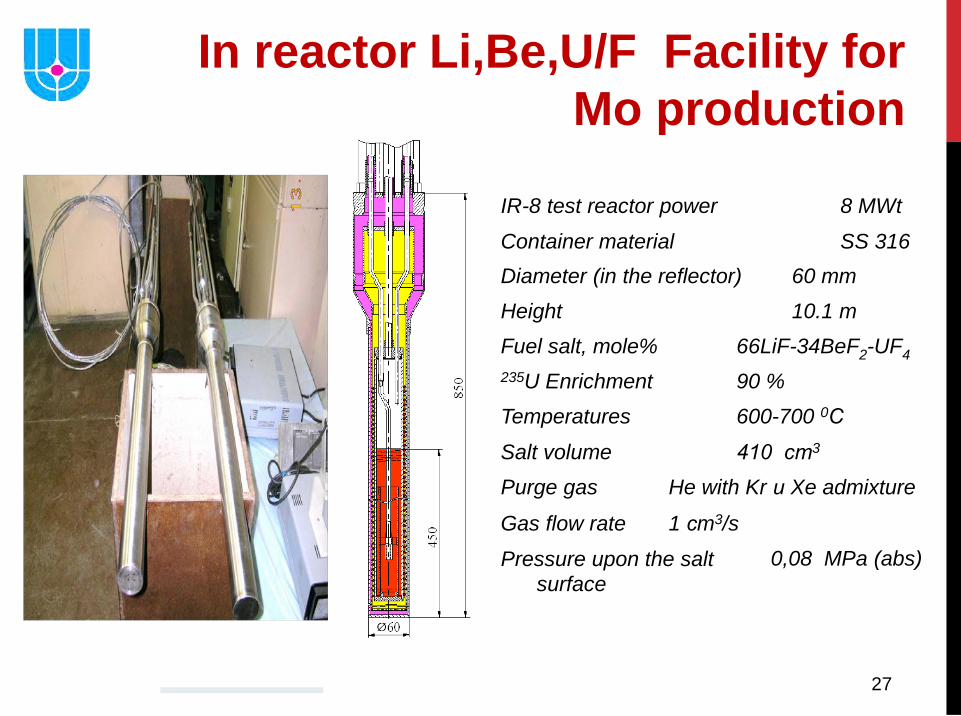
IR-8 test reactor power 8 MWt Container material SS 316 Diameter (in the reflector) 60 mm Height 10.1 m Fuel salt, mole% 66LiF-34BeF2-UF4 235U Enrichment 90 % Temperatures 600-700 0С Salt volume 410 сm3 Purge gas He with Kr и Xe admixture Gas flow rate 1 сm3/s Pressure upon the salt
surface 0,08 MPa (abs)
27
In reactor Li,Be,U/F Facility for Mo production
28
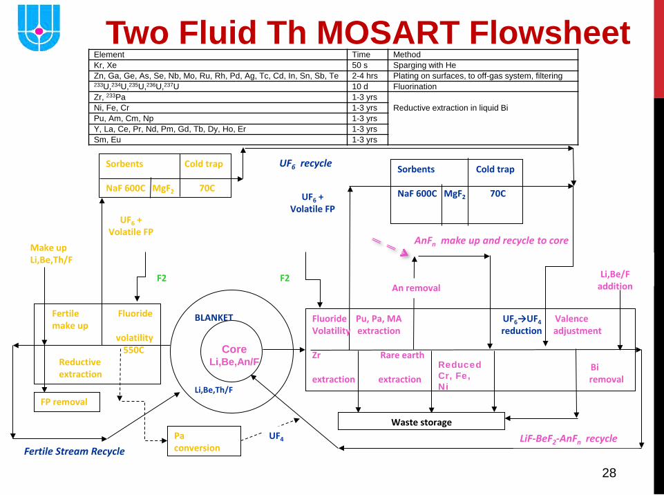
Core Li,Be,An/F
BLANKET Li,Be,Th/F
LiF-BeF2-AnFn recycle Fertile Stream Recycle
Fertile Fluoride make up volatility 550C Reductive extraction
Make up Li,Be,Th/F
UF6 + Volatile FP
UF6 + Volatile FP
UF6 recycle
Pa conversion
UF4
FP removal
Sorbents Cold trap NaF 600C MgF2 70C
Sorbents Cold trap NaF 600C MgF2 70C
AnFn make up and recycle to core
Fluoride Pu, Pa, MA UF6→UF4 Valence Volatility extraction reduction adjustment Zr Rare earth Bi extraction extraction removal
Waste storage
F2
F2
An removal
Reduced Cr, Fe, Ni
Li,Be/F
addition
Two Fluid Th MOSART Flowsheet Element Time Method Kr, Xe 50 s Sparging with He Zn, Ga, Ge, As, Se, Nb, Mo, Ru, Rh, Pd, Ag, Tc, Cd, In, Sn, Sb, Te 2-4 hrs Plating on surfaces, to off-gas system, filtering 233U,234U,235U,236U,237U 10 d Fluorination Zr, 233Pa 1-3 yrs
Reductive extraction in liquid Bi
Ni, Fe, Cr 1-3 yrs Pu, Am, Cm, Np 1-3 yrs Y, La, Ce, Pr, Nd, Pm, Gd, Tb, Dy, Ho, Er 1-3 yrs Sm, Eu 1-3 yrs
29
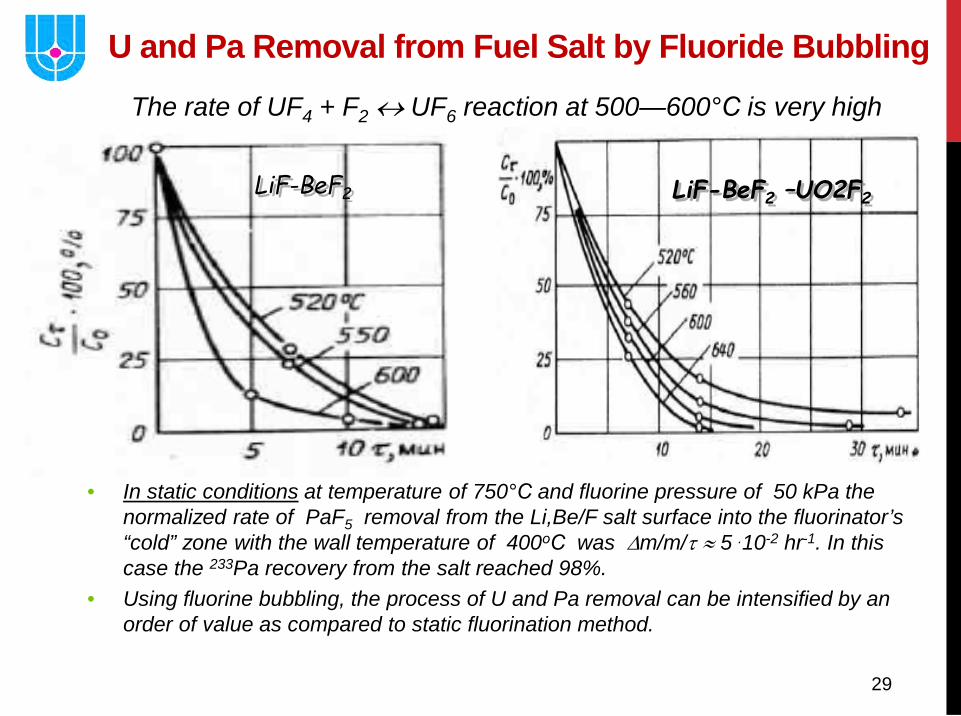
U and Pa Removal from Fuel Salt by Fluoride Bubbling
LiF-BeF2 LiF-BeF2 –UO2F2
• In static conditions at temperature of 750°С and fluorine pressure of 50 kPa the normalized rate of PaF5 removal from the Li,Be/F salt surface into the fluorinator’s “cold” zone with the wall temperature of 400оС was ∆m/m/τ ≈ 5 .10-2 hr-1. In this case the 233Pa recovery from the salt reached 98%.
• Using fluorine bubbling, the process of U and Pa removal can be intensified by an order of value as compared to static fluorination method.
The rate of UF4 + F2 ↔ UF6 reaction at 500—600°С is very high
30
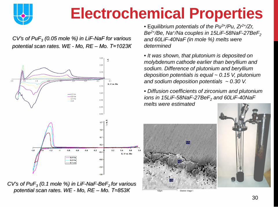
Electrochemical Properties CV’s of PuF3 (0.05 mole %) in LiF-NaF for various potential scan rates. WE - Mo, RE – Mo. Т=1023К
CV’s of PuF3 (0.1 mole %) in LiF-NaF-BeF2 for various potential scan rates. WE - Mo, RE – Mo. Т=853К
• Equilibrium potentials of the Pu3+/Pu, Zr2+/Zr, Be2+/Be, Na+/Na couples in 15LiF-58NaF-27BeF2 and 60LiF-40NaF (in mole %) melts were determined
• It was shown, that plutonium is deposited on molybdenum cathode earlier than beryllium and sodium. Difference of plutonium and beryllium deposition potentials is equal ~ 0.15 V, plutonium and sodium deposition potentials ~ 0.30 V.
• Diffusion coefficients of zirconium and plutonium ions in 15LiF-58NaF-27BeF2 and 60LiF-40NaF melts were estimated
31
-3
-2
-1
0
1
-3 -2 -1 0
lg X(Na)
lg D
(Pu
), lg
D(N
d)
lg D(Pu)lg D(Nd)
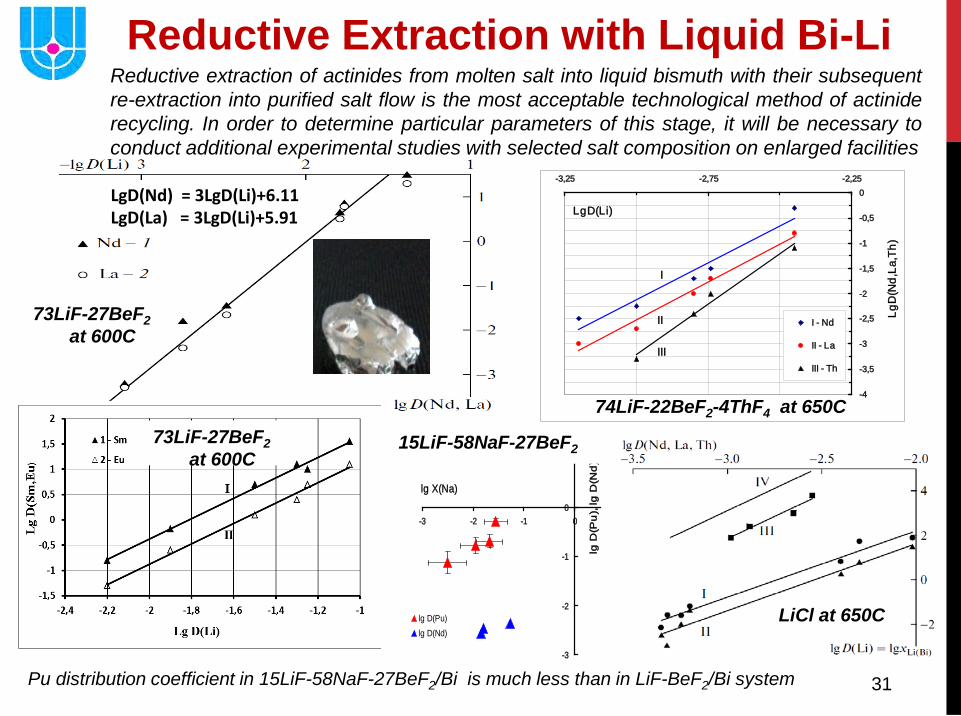
Reductive Extraction with Liquid Bi-Li
-4
-3,5
-3
-2,5
-2
-1,5
-1
-0,5
0-3,25 -2,75 -2,25
LgD(Li)
LgD
(Nd,
La,T
h)
I - Nd
II - La
III - Th
I
II
III
74LiF-22BeF2-4ThF4 at 650C
73LiF-27BeF2 at 600C
LgD(Nd) = 3LgD(Li)+6.11 LgD(La) = 3LgD(Li)+5.91
LiCl at 650C
Reductive extraction of actinides from molten salt into liquid bismuth with their subsequent re-extraction into purified salt flow is the most acceptable technological method of actinide recycling. In order to determine particular parameters of this stage, it will be necessary to conduct additional experimental studies with selected salt composition on enlarged facilities
15LiF-58NaF-27BeF2
Pu distribution coefficient in 15LiF-58NaF-27BeF2/Bi is much less than in LiF-BeF2/Bi system
73LiF-27BeF2 at 600C
32
• The molten salts have many desirable properties for mentioned above applications, and it seems likely that – given sufficient development time and money - a successful burner or breeder system could be developed
• Introduction of MSR technology to nuclear power might include 3 stages: FSCR, MSCR and MOSART
• It is obvious from the discussion above that use of molten fluorides as coolant and fuel for a reactor system of new fuel production or incinerator type operating in critical or fusion driven modes faces a large number of formidable problems. Several of these have been solved, and some seem to be well on the way to solution. But it is also clear that some still remain to be solved
• It may even be uncertain whether such a system would serve a useful purpose if its successful development were assured. It is certain that effort to date has thrown light on e. g. much elegant high temperature non-aqueous chemistry and has shown how molten salts can operate under hard and strong conditions
• Finally, it open perspectives significantly different to the present reactor and fuel cycle technology
Summary