Embed Size (px)
Citation preview
Material behavior in metal forming
R. Chandramouli
Associate Dean-Research
SASTRA University, Thanjavur-613 401
NPTEL - Mechanical Engineering - Forming
Joint Initiative of IITs and IISc – Funded by MHRD Page 1 of 13
Table of Contents 5.1 Flow stress: ............................................................................................................................... 3
5.2 Work done in deformation processing: ..................................................................................... 4
5.3 Deformation zone geometry: .................................................................................................... 6
5.4 Friction in metal forming: .......................................................................................................... 7
5.5 Effect of temperature in metal forming: ................................................................................... 9
5.5.1 Cold and hot forming: ....................................................................................................... 10
5.6 Workability: ............................................................................................................................. 11
NPTEL - Mechanical Engineering - Forming
Joint Initiative of IITs and IISc – Funded by MHRD Page 2 of 13
5.1 Flow stress: Flow stress is the stress required to sustain a certain plastic strain on the material. Flow stress can be determined form simple uniaxial tensile test, homogeneous compression test, plane strain compression test or torsion test.In forming of materials, we are concerned with flow stress of material being formed, as this affects the ability of material to undergo deformation. Factors such as strain rate, temperature, affect the flow stress of materials. A simple power law expression for flow stress of a material which does not show anisotropy can be expressed as:
where n is known as strain hardening exponent.
Higher strain hardening exponent values enhance the flow stress. Similarly, flow stress is enhanced with increase in strain rate during a plastic deformation process.
Effect of strain rate on flow stress becomes more pronounced at higher temperatures. AT higher temperatures [hot working], strain hardening may not have effect on flow stress. However, during cold working effect of strain on flow stress cannot be neglected. In such cases, average flow stress can be determined between two given strains.
In hot forming, temperatures of working are above recrystallization temperature. Therefore, the grains of the metal get elongated along direction normal to applied force, giving raise to anisotropy. During recovery process, locked up dislocations get released. Residual stresses are reduced. Recrystallisation of new grains can happen when the metal gets heated above recrystallization temperature. Secondary grain growth may follow primary recrystallization. In hot working, metal may get softened after hot deformation process. Recrystallised grain size affects the flow stress of material.
A general expression for flow stress, encompassing temperature, strain, strain rate, recrystallisation has been given in the form:
n is strain hardening exponent, m is strain rate sensitivity exponent, T is temperature.
Materials are subjected to complex states of stresses during forming. Stress required for forming, yield or flow stress therefore depends on several factors, such as strain, strain rate, temperature etc.
NPTEL - Mechanical Engineering - Forming
Joint Initiative of IITs and IISc – Funded by MHRD Page 3 of 13
From the uniaxial tensile test, one can understand material behavior considerably. Form the tensile test data, we can determine flow stress, though this method has limitations due to localized deformation called necking.
Flow curve is the stress-strain curve for a material in the plastic range. It describes material behavior in metal forming. From flow curve, we can determine the flow stress as
σ = kε
where ε is maximum strain during deformation process and n is strain
hardening exponent.
n
In forming processes, such as forging, the instantaneous flow stress can be found from the flow curve, as the stress required to cause a given strain or deformation.
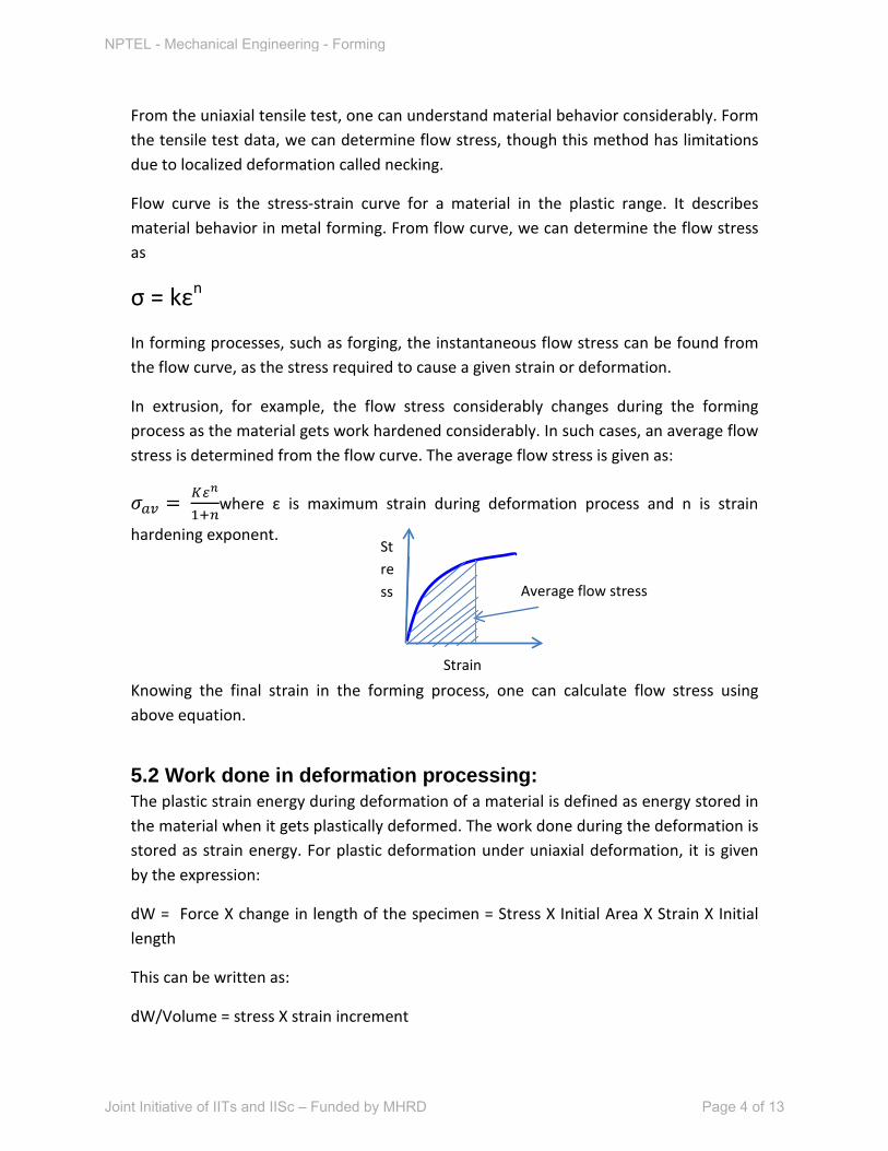
In extrusion, for example, the flow stress considerably changes during the forming process as the material gets work hardened considerably. In such cases, an average flow stress is determined from the flow curve. The average flow stress is given as:
Knowing the final strain in the forming process, one can calculate flow stress using above equation.
5.2 Work done in deformation processing: The plastic strain energy during deformation of a material is defined as energy stored in the material when it gets plastically deformed. The work done during the deformation is stored as strain energy. For plastic deformation under uniaxial deformation, it is given by the expression:
dW = Force X change in length of the specimen = Stress X Initial Area X Strain X Initial length
This can be written as:
dW/Volume = stress X strain increment
Average flow stress
Strain
Stress
NPTEL - Mechanical Engineering - Forming
Joint Initiative of IITs and IISc – Funded by MHRD Page 4 of 13
Strain energy per unit volume = stress X strain increment
du = σdε
This upon integration between zero strain and a finite plastic strain ε, gives:
u =
For triaxial stress, the plastic work per unit volume is given as:
du = σ1dε1 + σ2dε2+σ3dε
3
This energy represents the minimum energy required for deformation without friction, redundant deformation etc.
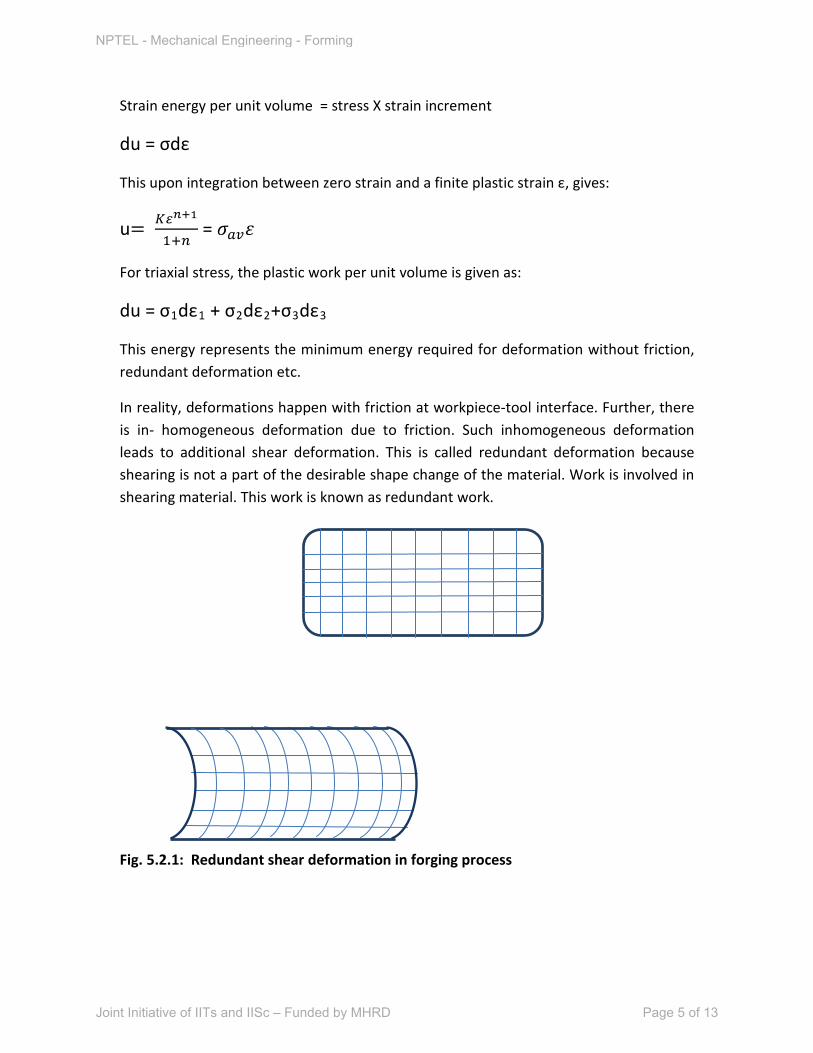
In reality, deformations happen with friction at workpiece-tool interface. Further, there is in- homogeneous deformation due to friction. Such inhomogeneous deformation leads to additional shear deformation. This is called redundant deformation because shearing is not a part of the desirable shape change of the material. Work is involved in shearing material. This work is known as redundant work.
Fig. 5.2.1: Redundant shear deformation in forging process
NPTEL - Mechanical Engineering - Forming
Joint Initiative of IITs and IISc – Funded by MHRD Page 5 of 13
5.3 Deformation zone geometry: Bulk deformation of materials happen generally within converging die shapes. The small region of the die through which the metal is subjected to plastic deformation is called deformation zone.
Geometry or shape of the deformation zone affects the redundant deformation work, and hence the total forming force.
Deformation zone geometry also affects the residual stress, internal defects during forming.
Deformation zone geometry is defined by the parameter Δ. This parameter is defined as ratio of thickness or height of deformation zone to contact length of deformation zone.
Δ = h / L
For extrusion it can be shown that h = (ho + hf)/2 and L = (ho - hf
)/2Sinα. This factor increases with increasing die angle and decreases with reduction.
Redundant strain is expressed by a parameter φ, which is a function of Δ.
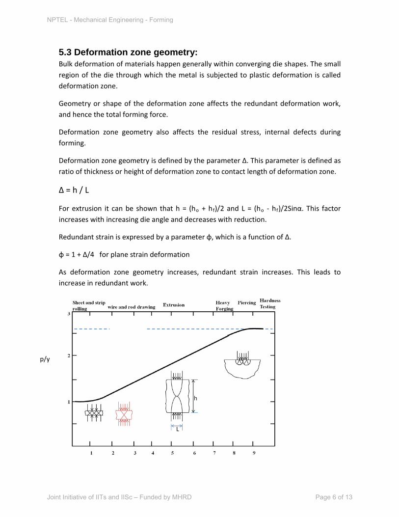
φ = 1 + Δ/4 for plane strain deformation
As deformation zone geometry increases, redundant strain increases. This leads to increase in redundant work.
p/y
NPTEL - Mechanical Engineering - Forming
Joint Initiative of IITs and IISc – Funded by MHRD Page 6 of 13
Fig. 5.3.1: Effect of deformation zone geometry parameter on various forming processes
As observed from the above diagram, the deformation pressure increases with increase in deformation zone geometry, due to increase in redundant work. Also smaller h/L value, lower is forming pressure – in the absence of friction. However, effect of friction increases in smaller h/L cases. High Δ leads to high residual stress in the formed part.
Friction in forming is considered in the next section.
The total energy required during forming can be now written as:
utotal = uideal + ufriction + uredundant
Forming efficiency is now defined as η = uideal / u
5.4 Friction in metal forming:
total
Rolling process has a high efficiency of 75 to 95% due to its low redundant deformation and smaller deformation zone geometry. Whereas, processes with high deformation zone geometry, such as forging and extrusion have low efficiency, 30 to 65%.
Surface asperities on two surfaces in contact get interlocked with each other. When a surface tends to slide against another stationary surface, say a die surface, there is a shear stress induced at interface which opposes the flow of material. This condition is called sliding friction.
Condition of sliding friction or sticking friction can arise at the interface between the workpiece and die/tool in forming operations.
Sliding friction arises due to surface shear stress opposing the metal flow. Friction is undesirable as it increases the deformation work required, leads to non-homogeneous deformation of material, causes tool wear, causes residual stress in the product and may lead to cracking of surface.
Coefficients of friction in forming processes are quiet high. If coefficient of friction becomes very high it leads to a situation called sticking friction. In this case, the surface
Δ
NPTEL - Mechanical Engineering - Forming
Joint Initiative of IITs and IISc – Funded by MHRD Page 7 of 13
shear stress exceeds shear yield strength of material, the two surfaces adhere to each other. Metal beneath the surface undergoes shear deformation.
Theoretical forming pressure without friction is: p = σf[flow stress].
With sliding friction, having coefficient of Coulomb friction μ = τ/p, the forming pressure increases exponentially along the interface, as given below for a disc under forging:
P = σf(exp2μ/h(a-r)), where h is height of billet, a is radius of the cylindrical billet.
As a result of friction, forming pressure rises exponentially, forming a friction hill in the lateral direction.
Friction factor m is sometimes used in place of coefficient of friction.
m = τ / k , where k is shear yield strength.
m is independent of normal pressure at interface and it is easy to measure.
Use of Coulomb coefficient of friction is sometimes misleading, as we find from the definition of coefficient of friction that μ decreases with increasing pressure, which is not correct.
Therefore, m is preferred in analysis of friction– especially in hotworking.
Lubrication is necessary in order to reduce friction in metal forming.
For cold forming operations, fats, fatty acids, mineral oils, soap emulsions are generally used. For hot forming, glass, graphite, mineral oils can be used as lubricants.
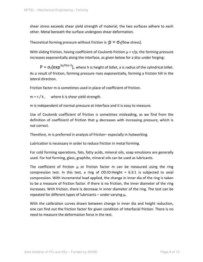
The coefficient of friction μ or friction factor m can be measured using the ring compression test. In this test, a ring of OD:ID:Height = 6:3:1 is subjected to axial compression. With incremental load applied, the change in inner dia of the ring is taken to be a measure of friction factor. If there is no friction, the inner diameter of the ring increases. With friction, there Is decrease in inner diameter of the ring. The test can be repeated for different types of lubricants – under varying μ.
With the calibration curves drawn between change in inner dia and height reduction, one can find out the friction factor for given condition of interfacial friction. There is no need to measure the deformation force in the test.
NPTEL - Mechanical Engineering - Forming
Joint Initiative of IITs and IISc – Funded by MHRD Page 8 of 13
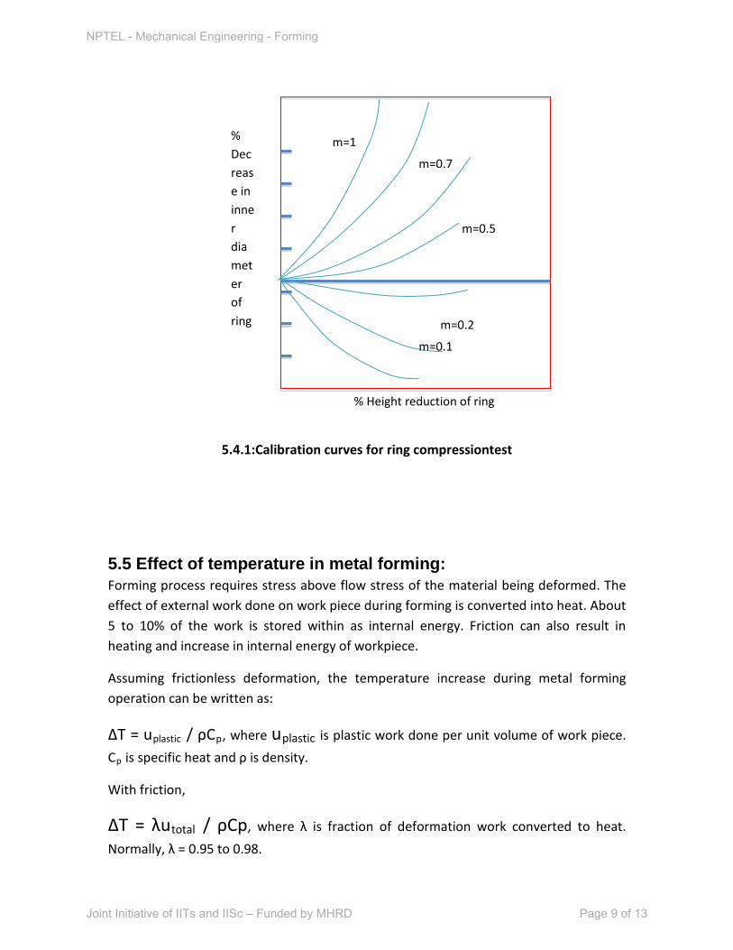
5.4.1:Calibration curves for ring compressiontest
5.5 Effect of temperature in metal forming: Forming process requires stress above flow stress of the material being deformed. The effect of external work done on work piece during forming is converted into heat. About 5 to 10% of the work is stored within as internal energy. Friction can also result in heating and increase in internal energy of workpiece.
Assuming frictionless deformation, the temperature increase during metal forming operation can be written as:
ΔT = uplastic / ρCp, where uplastic is plastic work done per unit volume of work piece.
Cp
ΔT = λu
is specific heat and ρ is density.
With friction,
total / ρCp, where λ is fraction of deformation work converted to heat.
Normally, λ = 0.95 to 0.98.
% Height reduction of ring
% Decrease in inner diameter of ring m=0.2
m=0.1
m=0.5
m=1
m=0.7
NPTEL - Mechanical Engineering - Forming
Joint Initiative of IITs and IISc – Funded by MHRD Page 9 of 13
Temperature rise is calculated using stress-strain curve, as the plastic work is calculated as the area under stress-strain curve for plastic flow.
For slow deformations, the temperature rise of the work piece may be small as the heat generated gets dissipated through the die, surrounding air, etc. However, adiabatic condition may prevail under large deformation speeds, resulting in large rise in temperature of the work piece. This may cause incipient melting. Therefore, strain rate also influences the temperature rise during working.
For low carbon steel, the temperature rise for a true strain of 1 has been estimated to be 553 K. This is without heat lost from the billet.
5.5.1 Cold and hot forming: Cold forming is carriedout at a temperature lower than recrystallization temperature of the work piece material. Hot working is a process carried out at temperatures above recrystallization temperature, namely, 0.6 Tm. High strain rates – 0.5 to 500 s-1
During hot working, material softening happens due to two mechanisms – dynamic recovery or dynamic recrystallization. In dynamic recovery, dislocation cross-slipping, climbing occurs. This mechanism is predominant in high stacking fault energy metals, with low activation energy for creep. On the other hand for metals with low stacking fault energy, like copper, nickel, the dynamic recrystallization is predominant mechanism of softening. During hot working static recovery can happen in between the working phases, thereby softening the metal. Rapid cooling after hot working may bypass this static recovery, thereby retaining the high strength of the metal. Strain induced precipitation or phase transformation can increase the flow stress, reduce
are involved in hot working. No strain hardening takes place in hot working. Processes of recrystallization, recovery and grain growth dominate in hot working. Energy required for hot working is low, as flow stress decreases with increase in temperature. Large strains ( ε = 2 to 4) are possible in hot forming because of recovery process. Due to oxidation on surface during hot working, poor surface finish and poor dimensional tolerences are inherent defects. Die wall chilling may result in non-uniform material flow.
Upper limit for hot working is hot shortness, in which the metal becomes brittle above a certain temperature due to grain boundary melting or melting of low melting phase such as sulfur in steel.
Metals with high thermal conductivity will require higher working temperatures or rapid working.
NPTEL - Mechanical Engineering - Forming
Joint Initiative of IITs and IISc – Funded by MHRD Page 10 of 13
ductility. Age hardenable (Al) alloys are subjected to freezing temperatures before forming, to suppress precipitation during forming. Thermo mechanical treatments can be used for achieving optimum levels of strength and hardness.
Cold working leads to work hardening. The formed material may have to be annealed to relieve internal stresses and reduce hardness and strength after cold forming. However, if high strength and hardness are desirable, normally cold worked structure is retained. Cold working has high dimensional accuracy.
Working on a metal at temperatures above room temperature but below recrystallization temperature is called warm working. Warm working may have the advantages of reduced working pressures, reduced levels of residual stresses and oxidation, improved surface finish and dimensional accuracy.
5.6 Workability: Materials differ in their ability to undergo plastic deformation. The extent of plastic deformation in a material is dependent on the materials grain structure, nature of bonding, presence of defects like dislocation and external factors such as temperature. Workability is the ease with which a material can be subjected to plastic deformation to achieve the desired shape without crack formation. In case of ductile materials the limit of forming is dictated by the beginning of necking. Once necking starts, due to localized deformation, further deformation of the work piece to finished shape becomes impossible. Therefore, in most of materials, the starting of necking is considered as the limit of working or forming. Workability is dependent on material characteristics and external factors such as tool and die geometry, friction, strain rate etc.
The other criterion for workability may be the formation of cracks on the surface or within the material during the forming process. Cracks on external surface may form due to excessive tensile loads or friction. Internal cracks may form due to the presence of voids, second phase particles etc. Necking during tensile deformation may result in formation of voids, which may grow in size during loading. Cracks result due to excessive growth of voids and their coalescence. In compressive loading, generally surface cracks are formed due to excessive tensile stresses induced on the bulged surfaces. Bulging is a non-uniform deformation during compressive loading of billets.
A generalized fracture criterion may serve as a way of establishing workability of ductile materials. Combinations of stress and strain in ductile materials can lead to fracture unless the tensile stress induced reaches a critical value. More easily, tensile and compressive strains are correlated with each other in order to arrive at a criterion for
NPTEL - Mechanical Engineering - Forming
Joint Initiative of IITs and IISc – Funded by MHRD Page 11 of 13
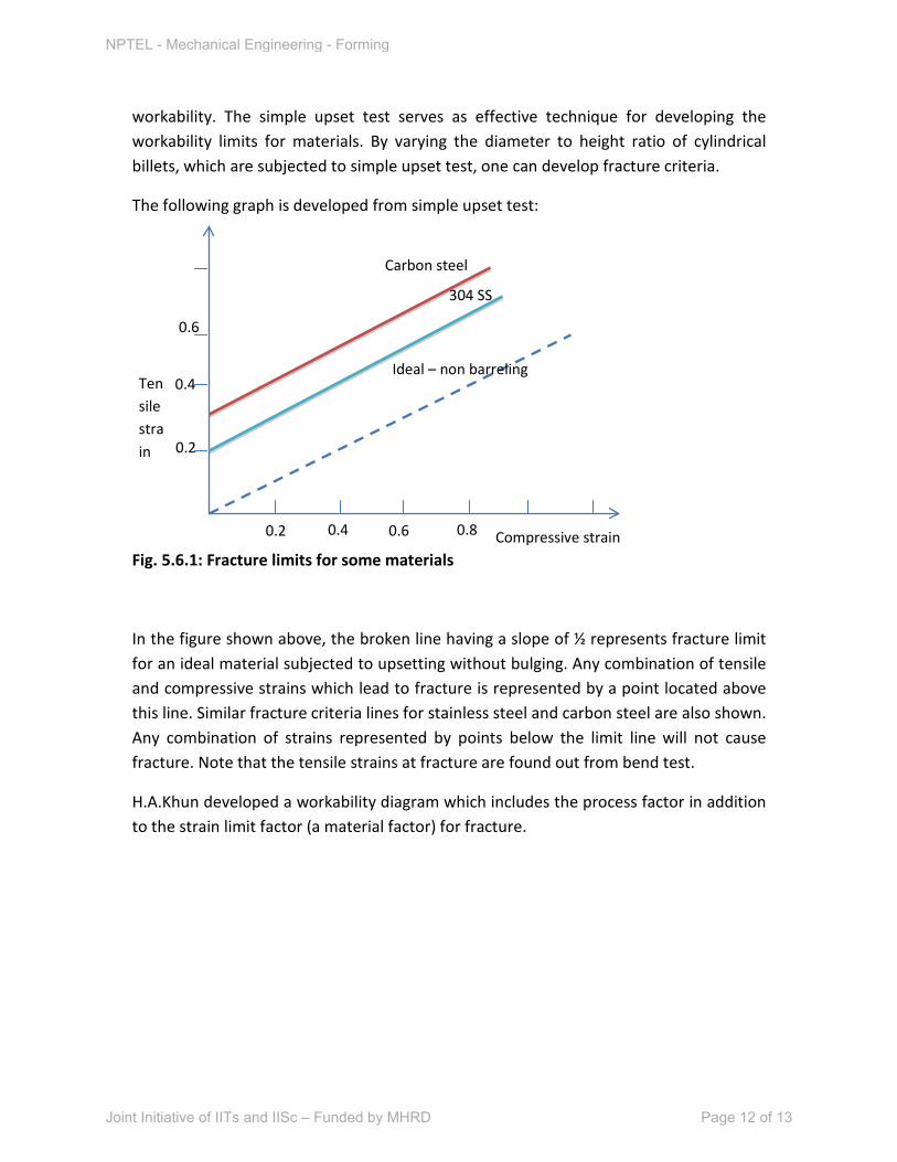
workability. The simple upset test serves as effective technique for developing the workability limits for materials. By varying the diameter to height ratio of cylindrical billets, which are subjected to simple upset test, one can develop fracture criteria.
The following graph is developed from simple upset test:
Fig. 5.6.1: Fracture limits for some materials
In the figure shown above, the broken line having a slope of ½ represents fracture limit for an ideal material subjected to upsetting without bulging. Any combination of tensile and compressive strains which lead to fracture is represented by a point located above this line. Similar fracture criteria lines for stainless steel and carbon steel are also shown. Any combination of strains represented by points below the limit line will not cause fracture. Note that the tensile strains at fracture are found out from bend test.
H.A.Khun developed a workability diagram which includes the process factor in addition to the strain limit factor (a material factor) for fracture.
Tensile strain
Compressive strain
304 SS
Carbon steel
Ideal – non barreling
0.2 0.4 0.6 0.8
0.2
0.4
0.6
NPTEL - Mechanical Engineering - Forming
Joint Initiative of IITs and IISc – Funded by MHRD Page 12 of 13
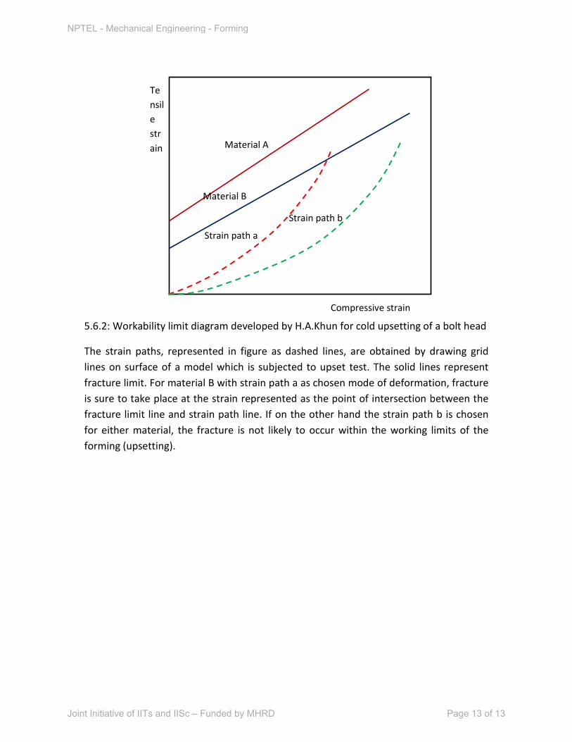
5.6.2: Workability limit diagram developed by H.A.Khun for cold upsetting of a bolt head
The strain paths, represented in figure as dashed lines, are obtained by drawing grid lines on surface of a model which is subjected to upset test. The solid lines represent fracture limit. For material B with strain path a as chosen mode of deformation, fracture is sure to take place at the strain represented as the point of intersection between the fracture limit line and strain path line. If on the other hand the strain path b is chosen for either material, the fracture is not likely to occur within the working limits of the forming (upsetting).
Tensile strain
Compressive strain
Material A
Material B
Strain path a
Strain path b
NPTEL - Mechanical Engineering - Forming
Joint Initiative of IITs and IISc – Funded by MHRD Page 13 of 13