Embed Size (px)
Citation preview
Optoelectrofluidic behavior of metal–polymer hybrid colloidal particlesDongsik Han, Hyundoo Hwang, and Je-Kyun Park Citation: Appl. Phys. Lett. 102, 054105 (2013); doi: 10.1063/1.4790622 View online: http://dx.doi.org/10.1063/1.4790622 View Table of Contents: http://apl.aip.org/resource/1/APPLAB/v102/i5 Published by the American Institute of Physics. Related ArticlesIntroducing a well-ordered volume porosity in 3-dimensional gold microcantilevers Appl. Phys. Lett. 102, 053501 (2013) Computational analysis of the effect of surface roughness on the deflection of a gold coated silicon micro-cantilever J. Appl. Phys. 113, 054501 (2013) Editorial: Moving on in biomicrofluidics Biomicrofluidics 7, 010401 (2013) Perspective: Flicking with flow: Can microfluidics revolutionize the cancer research? Biomicrofluidics 7, 011811 (2013) Experimental validation of numerical study on thermoelectric-based heating in an integrated centrifugalmicrofluidic platform for polymerase chain reaction amplification Biomicrofluidics 7, 014106 (2013) Additional information on Appl. Phys. Lett.Journal Homepage: http://apl.aip.org/ Journal Information: http://apl.aip.org/about/about_the_journal Top downloads: http://apl.aip.org/features/most_downloaded Information for Authors: http://apl.aip.org/authors

Optoelectrofluidic behavior of metal–polymer hybrid colloidal particles
Dongsik Han,a) Hyundoo Hwang,a) and Je-Kyun Parkb)
Department of Bio and Brain Engineering, Korea Advanced Institute of Science and Technology (KAIST),291 Daehak-ro, Yuseong-gu, Daejeon 305-701, Republic of Korea
(Received 16 November 2012; accepted 23 January 2013; published online 5 February 2013)
Behavior of metal–polymer hybrid colloidal particles in an optoelectrofluidic device has been
investigated theoretically and experimentally. In the application of hundreds of kHz ac voltage, a
variety of optically induced electrokinetic and electrostatic mechanisms affect the movement of
gold-coated polystyrene microspheres. The particles repel from the light pattern, and their mobility
increases as the amount of gold increases. We apply this model to develop an optoelectrofluidic
immunoassay, in which the corresponding metal–polymer hybrid particles are formed by a reaction
of antibody-coated gold nanoparticles, antigens, and antibody-coated polystyrene microspheres.VC 2013 American Institute of Physics. [http://dx.doi.org/10.1063/1.4790622]
Optoelectrofluidics refers to the study of motion of par-
ticles and fluids under an electric field induced or perturbed
by an optical field.1 Among several types of optoelectrofluidic
technologies, optoelectronic tweezers (OET),2 which is based
on optical-to-electrical energy transfer process via a photocon-
ductive layer, has come into the spotlight as a powerful tech-
nology for programmable optical manipulation. The OET has
been applied not only for manipulation of biological materials
such as blood cells,3 oocytes,4 sperms,5 ciliates,6 and biomole-
cules7 but also for analytical applications, including molecular
diffusion measurement,8 sandwich immunoassays,9 and a
surface-enhanced Raman scattering-based molecular detec-
tion.10 In addition, a variety of physical phenomena occurred
in the OET device have also been heavily studied.11–14
Hybrid colloidal particles have unique properties that
cannot be found in homogeneous materials. For instance,
metal–polymer hybrid colloidal particles could be utilized in
electronic15 and photonic16 applications due to the conduc-
tivity and permittivity of their metallic composition without
losing intrinsic advantages of polymer particles such as
versatility and easiness in manipulation and modification.
These unique properties have led the metal–polymer hybrid
colloidal particles to be studied actively in recent years. For
example, they could perform a role to detect analytes spec-
troscopically, particularly in immunoassays by coating with
metallic materials.17 Besides, optically encoded micropar-
ticles, which can be used in multi-colored assays such as
DNA hybridization study, were developed by linking quan-
tum dots.18 Metal–silica hybrid nanostructures for surface-
enhanced Raman spectroscopy are also demonstrated, and
each structure can be yielded as a hybrid particle.19 To inves-
tigate physical characteristics in electric field, dielectric
properties of a metal–polymer hybrid particle have also been
studied.20
In this letter, we describe a behavior of metal–polymer
hybrid colloidal particles in an optoelectrofluidic system,
where a variety of optically-induced electrokinetic and elec-
trostatic forces act on the particle movements in concert. We
also propose an immunoassay platform based on the change
in optoelectrofluidic motility of immunocomplexes, which
are metal–polymer colloidal particles composed of polysty-
rene (PS) microspheres and gold nanoparticles (AuNPs) with
target antigens.
The optoelectrofluidic device, which consists of two par-
allel plates, is schematically presented in Fig. 1(a). The upper
plate is a glass substrate coated with indium tin oxide (ITO),
and the bottom plate is a photoconductive layer-coated ITO–
glass substrate. The photoconductive layer in the bottom plate
was fabricated by sequential deposition of three layers: (1) a
50 nm-thick heavily doped hydrogenated amorphous silicon
(a-Si:H); (2) an 1 lm-thick intrinsic a-Si:H, and (3) a 20 nm-
thick silicon nitride on the ITO-coated glass substrate using a
plasma enhanced chemical vapor deposition method. An 1 ll
of sample droplet containing colloidal particles was placed in
an 80 lm-height liquid chamber between those two plates,
FIG. 1. Schematic illustration of (a) the optoelectrofluidic device and
(b) synthesis of a AuNPs–PS hybrid particle. The hybrid particles were
formed via immunoreaction of antibody (Ab)-conjugated AuNPs, antigens,
and Ab-conjugated PS microbeads.
a)D. Han and H. Hwang contributed equally to this work.b)Electronic mail: [email protected]. Tel.: þ82-42-350-4315. Fax:
þ82-42-350-4310.
0003-6951/2013/102(5)/054105/4/$30.00 VC 2013 American Institute of Physics102, 054105-1
APPLIED PHYSICS LETTERS 102, 054105 (2013)

and then an ac voltage of 20 Vpeak–peak with 100 kHz was
applied across the ITO electrodes. When a light pattern
produced by a liquid crystal display was projected onto the
photoconductive layer, only the illuminated area became con-
ductive, resulting in a nonuniform electric field in the liquid
chamber. As a consequence, metal–polymer hybrid particles in
the sample droplet were forced to move via optically induced
electrokinetic mechanisms. In this study, gold-linked PS par-
ticles were used as the metal–polymer hybrid particles. They
were synthesized by immunoreaction of 6 lm carboxylated PS
microbeads (Polysciences, Inc., Warrington, PA) conjugated
with goat anti-mouse IgG (Sigma–Aldrich, St. Louis, MO),
normal mouse IgG, and goat anti-mouse IgG-conjugated
AuNPs (5 nm in diameter; Sigma–Aldrich), as shown in Fig.
1(b). To conjugate the anti-IgGs to the microbeads, a general
conjugation chemistry based on 1-ethyl-3(3-dimethylamino-
propyl)cabodiimide (EDC) plus sulfo-N-hydroxysuccinimide
(sulfo-NHS) was used.21 First, 30 ll of carboxylated PS
microbeads (2.10� 108 microbeads/ml) were transferred to
the microcentrifuge tube. Microbeads were washed by centrif-
ugation with deionized water at 10 000 g for 5 min three times
and resuspended in 300 ll of 0.1 M 2 -(N-morpholino)ethane-
sulfonic acid buffer (pH 6.0). To activate microbeads, 100 ll
of 460 mM sulfo-NHS and 100ll of 156 mM EDC were added
to a solution containing microbeads and incubated for 30 min
at room temperature. The resulting microbeads were collected
by centrifugation at 10 000 g for 3 min at 4 �C, and the superna-
tant was carefully discarded. The microbeads were resus-
pended in 100 ll of 0.15 M phosphate buffered saline (PBS)
buffer (pH 7.2), and the activated microbeads were incubated
with anti-IgGs for overnight in an automated mixer. The conju-
gated microbeads were finally washed three times with PBS
buffer and resuspended in 500 ll of the same buffer. 3 ll of
antibody-conjugated microbeads solutions were resuspended
in 37 ll PBS buffer and reacted with 20 ll of serial diluted
antigen solutions and 10ll of AuNP-linked secondary
antibody solutions for 10 min at room temperature in series.
After incubation, AuNP-linked PS microbeads were collected
by filtering and resuspended in 50 ll of deionized water.
When a light pattern was projected onto the photoconduc-
tive layer, the metal–polymer hybrid particles were focused
toward the upper electrode and moved away in a lateral direc-
tion from the light, which forms the virtual electrode
[Fig. 2(a)]. Here, the changes in the vertical position of the
particles could be observed using a microscope with a lens
having a relatively short depth of focus. The hybrid particle in
the upper image was synthesized by immunoreaction with
0.1 ng/ml IgG solution, and the bottom one was synthesized
with 1000 ng/ml IgG solution, which means the bottom one
has relatively large amounts of AuNPs on the PS particle sur-
face. The two metal–polymer hybrid particles both moved
away from the light pattern in a lateral direction but showed
different optoelectrofluidic mobility depending on the amount
of AuNPs they have. The AuNPs–PS hybrid particles with rel-
atively large amounts of AuNPs moved with higher velocity
than the hybrid particles linked with small amounts of AuNPs.
It is no wonder that the electrokinetic behavior of the hybrid
particles varies according to the amount of AuNPs, which
dominantly affects the electrical properties of the hybrid par-
ticles. Then, what phenomena are the causes of this behavior
difference according to the amount of metal particles? The
dielectrophoretic force acting on a particle is defined as
FDEP¼ 2pr3emRe[ƒCM]rE2, where r is the radius of the par-
ticles, em¼ e0er is the permittivity of the suspending medium,
where er is the relative permittivity of the fluid and e0 is the
permittivity of free space, Re[fCM] is the real part of the Clau-
sius–Mossotti (CM) factor, and E is the local electric field.
Re[fCM] of the metal–polymer hybrid particle can be
expressed as the proportional sum of those of homogeneous
polymer and metal-coated polymer as below
Re½fCM;metal�polymer hybrid particle�¼ð1�mÞ �Re½fCM;polymer�þm �Re½fCM;metal�coated polymer�;
where m is the metal-occupied ratio on the surface of metal–
polymer hybrid particle.22 The CM factor of homogeneous
polymer is described as
fCM; polymer ¼ðe�p � e�mÞðe�p þ 2e�mÞ
;
where ep* and em* are the complex permittivities of the polymer
particle and medium, respectively; e*¼ e� (r/x) j, where r
FIG. 2. (a) Microscopic images showing the motion of hybrid particles
according to antigen concentration (0.1 and 1000 ng/ml) in the application
of an ac voltage of 20 Vpeak–peak with 100 kHz (scale bar: 10 lm). White por-
tions are optically generated virtual electrodes. (b) Theoretically calculated
real part of CM factor for a AuNPs–PS hybrid particle against the fraction of
the gold-coated area in the hybrid particle surface. The real part of CM
factor increases in positive direction as the fraction of gold-coated area
increases from 0% to 40%. The inset graph shows the CM factor variation
near 100 kHz according to the fraction of gold-coated area from 0% to 1%.
Both graphs have the same unit.
054105-2 Han, Hwang, and Park Appl. Phys. Lett. 102, 054105 (2013)

is the conductivity, e is the permittivity, and x is the angular
frequency. Meanwhile, we applied a spherical shell model to
calculate the CM factor of metal-coated polymer particles.
According to the shell model, the CM factor of the metal-
coated polymer is described as
fCM;metal�coated polymer ¼ðe�mp � e�mÞðe�mp þ 2e�mÞ
:
Here, the metal-coated polymer particle complex per-
mittivity e�mp is given by e�mp ¼ e�metal[c3þ 2(e�p � e�metal)/
(ep*þ 2emetal* )]/[c3� (e�p � e�metal)/(ep*þ 2emetal* )] where the fac-
tor c is the radius ratio of a metal-coated polymer particle to
a polymer particle.23 As a result, Re[ƒCM, metal-polymer hybrid
particle] of the AuNP–PS hybrid particles that we used in this
study could be calculated against the amount of AuNPs on
the PS particle surface [Fig. 2(b)]. The assumed relative per-
mittivities of PS bead, AuNP, and medium that we used for
simulation are 2.55, 6.9, and 78, and their conductivities
are 2.3� 10�4, 4.5� 107, and 0.5� 10�4 S/m, respectively.
At a frequency of 100 kHz, Re[ƒCM, metal-polymer hybrid particle]
increases from negative value to positive value as the con-
centration of AuNP–PS hybrid particles increases. This
means that repulsion force by dielectrophoresis (DEP)
decreases as the concentration of AuNP–PS hybrid particles
increases. Although the hybrid particles having small
amounts of AuNPs should be more rapidly repelled from the
light pattern according to the calculation, our experimental
results showed a totally different tendency [Fig. 2(a)]. In
other words, the particle behaviors observed in this study are
inexplicable based on the conventional theories, in which
optically induced DEP plays the most dominant role on the
particle behaviors in the optoelectrofluidic devices in the
application of hundreds of kHz ac voltage.14,24
To account for the behavior of particles, here we have
two more mechanisms which should be occurred in the opto-
electrofluidic device as dominant as the optically induced
dielectrophoretic force. One is the ac electro-osmosis
(ACEO) flow, which is caused by the motion of ions along
the surface of electrode by a tangential electric field, can be
defined as hvslipi¼�kDRe[rqEt*]/2g, where kD is the Debye
length, rq is the charges contained in the electric double
layer, Et is tangential electric field, and g is the fluid viscos-
ity [see Fig. S1 in supplementary material25]. The other is
the electrostatic interaction between the particle and the
electrode surface, which is determined by Felectrostatic
¼ (�3p/2)emRe[ƒCM]2r2E2/(1þ hm/r)4, where hm is the sur-
face to surface distance between the particle and the
electrode.26
To further analyze the effect of these forces on particles’
movement, the forces affecting on the AuNPs–PS hybrid
particles in this optoelectrofluidic system were investigated
[Fig. 3(a)]. The particles are initially focused to the upper
side of the liquid chamber due to the vertical component of
the dielectrophoretic force. The particles near the electrode
surface are affected by the electrostatic particle–surface
interaction force, being attracted toward the electrode
surface.12 While the ACEO flows originally occur toward
the virtual electrode at the bottom of the liquid chamber,
the converged fluids from the virtual electrode flow in the
opposite direction at the top of the liquid chamber as shown
in Fig. 3(b). As a result, the hydrodynamic drag force by the
ACEO flows make the hybrid particle near the top electrode
moved from the light pattern in a lateral direction. The DEP
and the electrostatic particle–surface interaction forces
depend on Re[ƒCM], which is dependent on the amount of
AuNPs on the PS particle. According to the scanning elec-
tron microscopic analysis (data not shown), the fraction of
the gold-coated area in the hybrid particle surface was only
1% even after the immunoreaction with the highest antigen
concentration. Thus we can expect that Re[ƒCM] might still
be less than 0 even though it was slightly shifted toward the
positive in the AuNPs range we used [Fig. 2(b)]. With this
little change in Re[ƒCM], the sum of the vertical DEP force
and the electrostatic surface–particle interaction force, which
act as the normal force of the friction force, are weakened.
As a consequence, the friction force cancelling the hydrody-
namic drag force become weaker as the amount of AuNPs
increased, resulting in the increase of the net force in the lat-
eral direction. This behavior can be explained by our force
balance model as follows:
FACEO þFDEP lateral � k � ðFDEP vertical þFelectrostaticÞ �Fdrag ¼ 0;
where FACEO is the hydrodynamic drag force due to the
ACEO flow, FDEP_lateral and FDEP_vertical are the lateral and
the vertical components of the dielectrophoretic force,
respectively, Felectrostatic is the electrostatic surface–particle
interaction force, Fdrag is the drag force, and k is the friction
coefficient.
FIG. 3. (a) Force diagram on AuNPs–PS hybrid particles according to the
amount of gold nanoparticles. Red arrows represent the vertical and the lat-
eral components of the dielectrophoretic force. (b) Simulation of ACEO
flow velocity distribution generated in the optoelectrofluidic system.
054105-3 Han, Hwang, and Park Appl. Phys. Lett. 102, 054105 (2013)
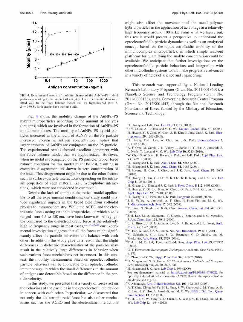
Fig. 4 shows the mobility change of the AuNPs–PS
hybrid microparticles according to the amount of analytes
(antigens) which are involved in the formation of AuNPs–PS
immunocomplexes. The motility of AuNPs–PS hybrid par-
ticles increased as the amount of AuNPs on the PS particle
increased; increasing antigen concentration implies that
larger amounts of AuNPs are conjugated on the PS particle.
The experimental results showed excellent agreement with
the force balance model that we hypothesized. However,
when no metal is conjugated on the PS particle, proper force
balance condition for this model might be lost, resulting in
exceptive disagreement as shown in zero concentration of
the inset. This disagreement might be due to the other factors
such as surface–particle interactions depending on the intrin-
sic properties of each material (i.e., hydrophobic interac-
tions), which were not considered in our model.
Despite the lack of complete theoretical model applica-
ble to all the experimental conditions, our study could pro-
vide significant impacts in the broad field from colloidal
physics to immunochemistry. While the ACEO and the elec-
trostatic forces acting on the microparticles, of which size is
ranged from 4.5 to 150 lm, have been known to be negligi-
ble compared to the dielectrophoretic force at the relatively
high ac frequency range in most cases,2,3,14,27,28 our experi-
mental investigation suggests that all the forces might signif-
icantly affect the particle behaviors and balance with each
other. In addition, this study gave us a lesson that the slight
differences in dielectric characteristics of the particles may
result in the relatively large differences in behavior when
such various force mechanisms act in concert. In this con-
text, the mobility measurement based on optoelectrofluidic
particle behaviors will be applicable to an optoelectrofluidic
immunoassay, in which the small differences in the amount
of antigens are detectable based on the difference in the par-
ticle velocity.
In this study, we presented that a variety of forces act on
the behaviors of the particles in the optoelectrofluidic device
in concert with each other. In particular, we discovered that
not only the dielectrophoretic force but also other mecha-
nisms such as the ACEO and the electrostatic interactions
might also affect the movements of the metal–polymer
hybrid particles in the application of ac voltage at a relatively
high frequency around 100 kHz. From what we figure out,
this result would present a perspective to understand the
optoelectrofluidic particle dynamics as well as an analytical
concept based on the optoelectrofluidic mobility of the
immunocomplex microparticles, in which simple read-out
platforms for quantifying the analyte concentration could be
available. We anticipate that further investigations on the
optoelectrofluidic particle behaviors and integration with
other microfluidic systems would make progressive advances
in a variety of fields of science and engineering.
This research was supported by a National Leading
Research Laboratory Program (Grant No. 2011-0018607), a
Nano/Bio Science and Technology Program (Grant No.
2011-0002188), and a Converging Research Center Program
(Grant No. 2012K001442) through the National Research
Foundation of Korea funded by the Ministry of Education,
Science and Technology.
1H. Hwang and J.-K. Park, Lab Chip 11, 33 (2011).2P. Y. Chiou, A. T. Ohta, and M. C. Wu, Nature (London) 436, 370 (2005).3H. Hwang, Y.-J. Choi, W. Choi, S.-H. Kim, J. Jang, and J.-K. Park, Elec-
trophoresis 29, 1203 (2008).4H. Hwang, D.-H. Lee, W. Choi, and J.-K. Park, Biomicrofluidics 3,
014103 (2009).5A. T. Ohta, M. Garcia, J. K. Valley, L. Banie, H. Y. Hsu, A. Jamshidi, S.
L. Neale, T. Lue, and M. C. Wu, Lab Chip 10, 3213 (2010).6W. Choi, S.-W. Nam, H. Hwang, S. Park, and J.-K. Park, Appl. Phys. Lett.
93, 143901 (2008).7H. Hwang and J.-K. Park, Anal. Chem. 81, 5865 (2009).8H. Hwang and J.-K. Park, Anal. Chem. 81, 9163 (2009).9H. Hwang, H. Chon, J. Choo, and J.-K. Park, Anal. Chem. 82, 7603
(2010).10H. Hwang, D. Han, Y. J. Oh, Y. K. Cho, K. H. Jeong, and J. K. Park, Lab
Chip 11, 2518 (2011).11H. Hwang, J.-J. Kim, and J.-K. Park, J. Phys. Chem. B 112, 9903 (2008).12H. Hwang, Y. Oh, J.-J. Kim, W. Choi, J.-K. Park, S.-H. Kim, and J. Jang,
Appl. Phys. Lett. 92, 024108 (2008).13H. Hwang, Y.-H. Park, and J.-K. Park, Langmuir 25, 6010 (2009).14J. K. Valley, A. Jamshidi, A. T. Ohta, H. Hsan-Yin, and M. C. Wu,
J. Microelectromech. Syst. 17, 342 (2008).15Y. Jung, N. Singh, and K.-S. Choi, Angew. Chem. Int. Ed. 48, 8331
(2009).16J.-H. Lee, M. A. Mahmoud, V. Sitterle, J. Sitterle, and J. C. Meredith,
J. Am. Chem. Soc. 131, 5048 (2009).17L. R. Hirsch, J. B. Jackson, A. Lee, N. J. Halas, and J. L. West, Anal.
Chem. 75, 2377 (2003).18M. Han, X. Gao, J. Z. Su, and S. Nie, Nat. Biotechnol. 19, 631 (2001).19M. Schierhorn, S. J. Lee, S. W. Boettcher, G. D. Stucky, and M.
Moskovits, Adv. Mater. 18, 2829 (2006).20Y.-J. Li, M. Xu, J.-Q. Feng, and Z.-M. Dang, Appl. Phys. Lett. 89, 072902
(2006).21G. T. Hermanson, Bioconjugate Techniques (Academic, New York, 1996),
p. 173.22L. Zhang and Y. Zhu, Appl. Phys. Lett. 96, 141902 (2010).23H. Morgan and N. G. Green, AC Electrokinetics: Colloids and Nanopar-
ticles (Research Studies, 2003), p. 341.24H. Hwang and J. K. Park, Lab Chip 9, 199 (2009).25See supplementary material at http://dx.doi.org/10.1063/1.4790622 for
optically induced AC electroosmosis (ACEO) flow in the optoelectroflui-
dic device and Fig. S1.26Z. Adamczyk, Adv. Colloid Interface Sci. 100–102, 267 (2003).27A. T. Ohta, Chiou Pei-Yu, H. L. Phan, S. W. Sherwood, J. M. Yang, A. N.
K. Lau, H. Y. Hsu, A. Jamshidi, and M. C. Wu, IEEE J. Sel. Top. Quan-
tum Electron. 13, 235 (2007).28Y.-H. Lin, Y.-W. Yang, Y.-D. Chen, S.-S. Wang, Y.-H. Chang, and M.-H.
Wu, Lab Chip 12, 1164 (2012).
FIG. 4. Experimental results of mobility change of the AuNPs–PS hybrid
particles according to the amount of analytes. The experimental data were
fitted well to the force balance model that we hypothesized (n¼ 15,
R2¼ 0.983). Both graphs have the same unit.
054105-4 Han, Hwang, and Park Appl. Phys. Lett. 102, 054105 (2013)