Embed Size (px)
Citation preview
DEGREE PROGRAMME IN WIRELESS COMMUNICATIONS ENGINEERING
MASTER’S THESIS
COORDINATED BEAMFORMING AND POWERCONTROL FOR NETWORK CONTROLLED
DEVICE-TO-DEVICE (D2D) COMMUNICATION
Author Amin Ghazanfari
Supervisor Docent Antti Tölli
Second Examiner Doctor Petri Komulainen
Technical Advisor Harri Pennanen
January, 2014
Ghazanfari A. (2014) Coordinated Beamforming and Power Control for NetworkControlled Device-to-Device (D2D) Communication. University of Oulu, Depart-ment of Communications Engineering, Master’s Degree Program in Wireless Commu-nications Engineering. Master’s thesis, 51 p.
ABSTRACT
Since the integration of data services into cellular communications, cellular ope-rators are struggling to harness the overwhelming data traffic on their networks.Underlay Device-to-Device (D2D) communication is a new and promising para-digm which allows proximate mobile users to have direct communication overthe cellular spectrum that may be reused by other cellular users in the same cell.This new paradigm is proposed to assist the cellular operators to deal with thebooming demand of mobile users. Recent studies have shown that underlay D2Dcommunication significantly increases the cellular network capacity, and enablescellular operators to support rich multimedia services. However, reusing cellularresources for both D2D and cellular communication introduces interference is-sues. In such systems, interference management is of utmost importance becauseimproper interference coordination may lead to a self-destructive network. Powercontrol and beamforming appears to be viable techniques for interference mana-gement which can also be used to enhance the energy efficiency of the system.
Network coordinated sum power optimization schemes for D2D communica-tions underlaying uplink and downlink cellular spectrum is considered in this the-sis. In particular, the system optimization target is to minimize the sum transmis-sion power while guaranteeing the user specific rate constraints. Novel algorithmsare proposed to solve the power minimization problem optimally. For the uplink,the problem is solved using joint transmit power control and receive beamfor-ming algorithm. The downlink problem is reformulated as a second-order coneprogram (SOCP), and thus, it can be solved efficiently via standard SOCP sol-vers. Moreover, a decentralized algorithm is proposed that reduces the amount ofcontrol information exchange in comparison to the centralized approach.
The performance of the proposed algorithms is compared with the conventionalcellular scheme. Simulation results demonstrate that the proposed underlay D2Dcommunication approach is capable of achieving significant performance gainsover the conventional cellular scheme. Results also illustrate that the power con-sumption of the system is highly affected by the location of the interfering cellu-lar user and whether the resources are shared in uplink or downlink. Therefore,four different resource sharing areas are defined for D2D communications. The-se areas specify the type of resources (i.e., downlink and uplink) suitable for D2Dcommunication.
Keywords: Device-to-Device communication, coordinated beamforming, powerminimization.
TABLE OF CONTENTS
ABSTRACT
TABLE OF CONTENTS
PREFACE
LIST OF SYMBOLS AND ABBREVIATIONS
1. INTRODUCTION 7
2. D2D COMMUNICATIONS IN CELLULAR NETWORKS 92.1. Definition and Taxonomy of D2D Communications . . . . . . . . . . 92.2. Advantages and Challenges of D2D Communications . . . . . . . . . 102.3. Use Cases . . . . . . . . . . . . . . . . . . . . . . . . . . . . . . . . 112.4. Overview of D2D Approaches . . . . . . . . . . . . . . . . . . . . . 122.5. Summary and Discussion . . . . . . . . . . . . . . . . . . . . . . . . 13
3. COORDINATED BEAMFORMING IN CELLULAR NETWORKS 143.1. Motivation and Background . . . . . . . . . . . . . . . . . . . . . . 143.2. Multi-cell Multi-user SIMO Uplink . . . . . . . . . . . . . . . . . . 15
3.2.1. Joint Transmit Power Control and Receive Beamforming . . . 163.3. Multi-cell Multi-user MISO Downlink . . . . . . . . . . . . . . . . . 16
3.3.1. Coordinated Beamforming via Uplink-Downlink Duality . . . 173.3.2. Coordinated Beamforming via Dual Decomposition . . . . . 19
4. POWER MINIMIZATION FOR NETWORK COORDINATED D2D COM-MUNICATIONS 22
4.1. System Model and Problem Formulation . . . . . . . . . . . . . . . . 224.2. Solution for Uplink Communications . . . . . . . . . . . . . . . . . 244.3. Solutions for Downlink Communications . . . . . . . . . . . . . . . 25
4.3.1. Centralized SOCP-based Algorithm . . . . . . . . . . . . . . 254.3.2. Decentralized Dual Decomposition-based Algorithm . . . . . 26
4.4. Practical Considerations . . . . . . . . . . . . . . . . . . . . . . . . 30
5. NUMERICAL EVALUATION 325.1. Simulation Model and Parameters . . . . . . . . . . . . . . . . . . . 325.2. Impact of Distance between D2D Users . . . . . . . . . . . . . . . . 335.3. Impact of Distance between Cellular User and D2D Pair . . . . . . . 375.4. Impact of SINR Targets . . . . . . . . . . . . . . . . . . . . . . . . . 40
6. DISCUSSION 43
7. SUMMARY 45
8. REFERENCES 46

PREFACE
This Master thesis has been carried out as part of the CRUCIAL project in the De-partment of Communications Engineering and Centre for Wireless Communications(CWC) at the University of Oulu, Finland. I would like to gratefully acknowledgethe Finnish Funding Agency for Technology and Innovation (Tekes), Nokia SolutionNetworks (NSN), Electrobit and Anite plc for supporting this project.
I would like to express my deepest appreciation to my supervisor Docent Antti Tölliwhose guidance and support helped me to overcome the obstacles of this research. Iwould also like to thank Dr. Petri Komulainen for his review.
My special thanks goes to M.Sc. (Tech.) Harri Penannen for his invaluable guidanceduring this thesis. I would also like to thank my friends Nastaran and Arash for theirsupport throughout the thesis.
Last but not least, I would like to thank my parents for their unconditional love andencouragement during my studies.
LIST OF SYMBOLS AND ABBREVIATIONS
B set of BSsdcu data symbol of cellular userdcu estimated data symbol of cellular userddtx data symbol from D2D transmitterddrx estimated data symbol of D2D transmitter in uplinkdj data symbol of user jdj estimated data symbol of user jgdtx,drx channel response between D2D transmitter and D2D receivergcu,drx channel response between cellular user and D2D receiverhb,j channel vector from user j to BS bhHb,j hermitian transpose of channel vector from user j to BS bhcu channel response between cellular user and BShdtx channel vector from D2D transmitter to BShdrx channel vector from BS to D2D receiverI identity matrixJ number of single antenna usersLdtx,drx distance between D2D transmitter and receiverl0 far field reference distancemj transmit beamformer vector towards user jmcu downlink transmit beamforming vector for cellular usernb additive white Gaussian noise vector at BS bnbs additive white Gaussian noise at BSndrx additive white Gaussian noise sample at receiver of D2D pairnj complex white Gaussian noise sample at user jN0 noise spectral densitypcu transmit power of cellular userpdtx transmit power of D2D transmitter in uplinkpdtx transmit power of D2D transmitter in downlinkpj transmit power of jth userr0 far field reference distanceRb cell radius of cellular BSRcu minimum rate target for cellular userRdrx minimum rate target for D2D pairT number of transmit antenna at BSU set of all active usersUb set of users that are served by BS b.wcu uplink receive beamforming vector for cellular userwj receive beamforming vector for user jwHj hermitian transpose of receive beamforming vector for user j
yj received downlink signal of user jydrx received signal at D2D receiverybs received signal vector at BSycu downlink received signal at cellular user
yb uplink received signal vector at BS bβcu complex scalar channel of cellular user without pathlossβdtx,drx i.i.d complex scalar channelα pathloss exponentλj transmit power for user j in dual uplinkσj scaling factor for user jψb,j inter-cell interference from BS b to user jψbb′,j local copy of inter-cell interference term at BS bγj target SINR of user jγcu fixed SINR target of cellular userγdrx fixed SINR target of D2D receiverµb vector of the dual variables associated with ψ(b)
ω the step-size in subgradient method
ADMM alternating direction method of multipliersBS base stationCSI channel state informationCR cognitive radioD2D device to deviceDL downlinkDEA D2D-exclusive-areaDL-EA downlink-exclusive-areaICI inter-cell interferenceISM industrial, scientific and medicalLTE long-term evolutionLTE-A long-term evolution-advancedMIMO multiple-input multiple-outputMISO multiple input single outputMMSE minimum mean square errorMVDR minimum variance dimensionless responseOFDMA orthogonal frequency-division multiple accessOSA open-sharing-areaQoS quality of serviceSINR signal to interference plus noise ratioSIMO single input multiple outputSOC second-order coneSOCP second-order cone programmingTDD time-division duplexingUL uplinkUL-EA uplink-exclusive-areaUMTS universal mobile telecommunications systemWLAN wireless local area networksWiMAX worldwide interoperability for Microwave AccessWSR weighted sum rateZF zero-forcing
7
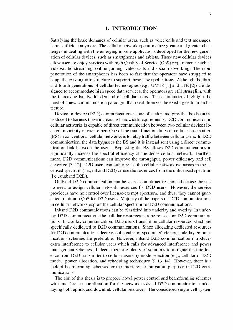
1. INTRODUCTION
Satisfying the basic demands of cellular users, such as voice calls and text messages,is not sufficient anymore. The cellular network operators face greater and greater chal-lenges in dealing with the emerging mobile applications developed for the new gener-ation of cellular devices, such as smartphones and tablets. These new cellular devicesallow users to enjoy services with high Quality of Service (QoS) requirements such asvideo/audio streaming, online gaming, video calls and social networking. The rapidpenetration of the smartphones has been so fast that the operators have struggled toadapt the existing infrastructure to support these new applications. Although the thirdand fourth generations of cellular technologies (e.g., UMTS [1] and LTE [2]) are de-signed to accommodate high speed data services, the operators are still struggling withthe increasing bandwidth demand of cellular users. These limitations highlight theneed of a new communication paradigm that revolutionizes the existing cellular archi-tecture.
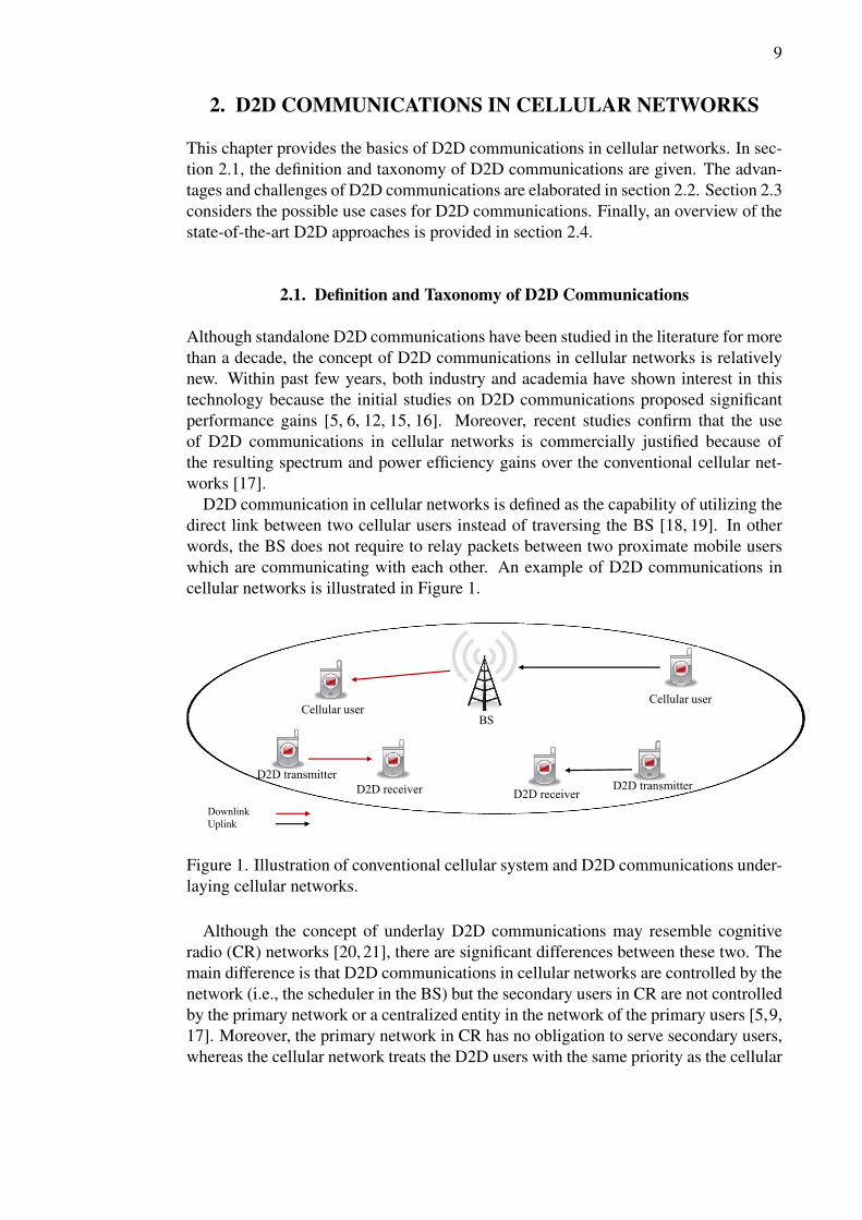
Device-to-device (D2D) communications is one of such paradigms that has been in-troduced to harness these increasing bandwidth requirements. D2D communication incellular networks is capable of direct communication between two cellular devices lo-cated in vicinity of each other. One of the main functionalities of cellular base station(BS) in conventional cellular networks is to relay traffic between cellular users. In D2Dcommunication, the data bypasses the BS and it is instead sent using a direct commu-nication link between the users. Bypassing the BS allows D2D communications tosignificantly increase the spectral efficiency of the dense cellular network. Further-more, D2D communications can improve the throughput, power efficiency and cellcoverage [3–12]. D2D users can either reuse the cellular network resources in the li-censed spectrum (i.e., inband D2D) or use the resources from the unlicensed spectrum(i.e., outband D2D).
Outband D2D communication can be seen as an attractive choice because there isno need to assign cellular network resources for D2D users. However, the serviceproviders have no control over license-exempt spectrum, and thus, they cannot guar-antee minimum QoS for D2D users. Majority of the papers on D2D communicationsin cellular networks exploit the cellular spectrum for D2D communications.
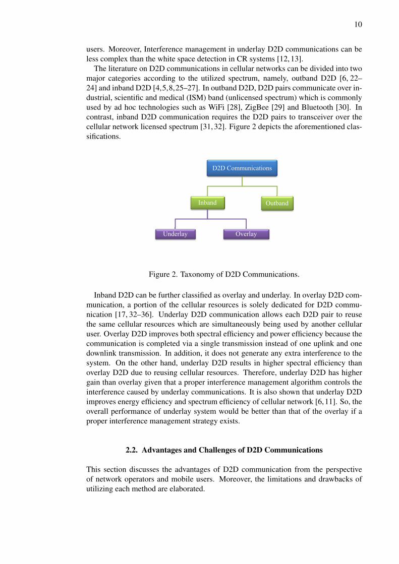
Inband D2D communications can be classified into underlay and overlay. In under-lay D2D communication, the cellular resources can be reused for D2D communica-tions. In overlay communication, D2D users transmit on cellular resources which arespecifically dedicated to D2D communications. Since allocating dedicated resourcesfor D2D communications decreases the gains of spectral efficiency, underlay commu-nications schemes are preferable. However, inband D2D communication introducesextra interference to cellular users which calls for advanced interference and powermanagement schemes. Indeed, there are plenty of solutions to mitigate the interfer-ence from D2D transmitter to cellular users by mode selection (e.g., cellular or D2Dmode), power allocation, and scheduling techniques [9, 13, 14]. However, there is alack of beamforming schemes for the interference mitigation purposes in D2D com-munications.
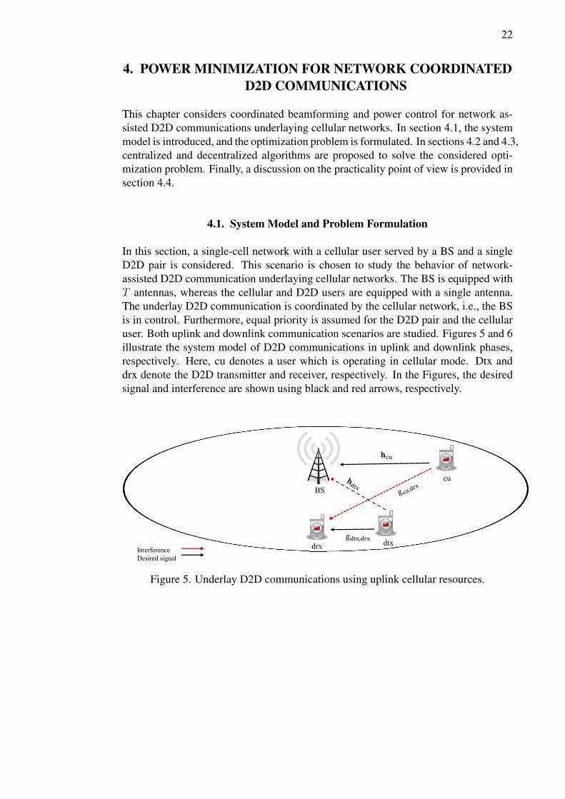
The aim of this thesis is to propose novel power control and beamforming schemeswith interference coordination for the network-assisted D2D communication under-laying both uplink and downlink cellular resources. The considered single-cell system
8
consists of a multi-antenna BS communicating with a cellular user, and an underlayingD2D user pair, which exploits the same radio resources. The optimization objective isto minimize the total transmission power of the system while satisfying the predefinedper user rate targets. In the uplink resource sharing case, a joint uplink power controland receive beamforming algorithm is proposed to solve the power minimization prob-lem. The optimal uplink powers for the users are obtained via fixed-point iterations,whereas the optimal receive beamforming at the BS is achieved by using the linearMMSE receiver. In the downlink resource sharing case, a centralized algorithm is pro-posed to solve the sum power optimization problem by reformulating it as a second-order cone program (SOCP), and solving it efficiently via standard SOCP solvers. Asa result, the optimal transmit power for the D2D user and the optimal transmit beam-former for the cellular user are obtained. This centralized algorithm performs all thecomputations at the BS side. Thus, it is required that the BS has the knowledge of allthe channels in the system. In this respect, a distributed algorithm is also proposedwhich potentially reduces the amount of exchanged control information between theBS and D2D transmitter. This algorithm utilizes standard dual decomposition methodto turn the original centralized optimization into two levels of optimizations, whichcan be then solved in a decentralized manner. The sum power performance of theproposed algorithms are numerically evaluated and compared with the conventionalcellular system via Matlab-based simulations.
The organization of this thesis is as follows. Chapter 2 provides an overview ofD2D communications in cellular networks. In Chapter 3, coordinated beamformingin cellular networks is considered. In Chapter 4, sum power minimization problemis introduced for underlying D2D communication, and centralized and decentralizedalgorithms are proposed to solve it. In Chapter 5, the proposed algorithms are nu-merically evaluated via Matlab-based simulations. Chapters 6 and 7 are dedicated todiscussion and summary of this thesis.
11
In D2D communication, users are expected to be in each other’s vicinity, and thus,it is generally expected to use lower transmission power in comparison to a cellulartransmission. Therefore, D2D communication potentially prolongs the battery life ofmobiles which is an existing challenge for smartphone producers, see e.g., [6,7,17,19,37]. This feature makes D2D communication specifically attractive for green mobilecommunications [4,7,8,17,38]. In addition to energy efficiency, D2D communicationscan lead to improved throughput and reduced delay for the same reasons (i.e., userproximity and direct communication link) [3, 8, 11, 12, 39].
The above mentioned merits are easier to achieve using inband D2D rather than out-band D2D. For instance, outband D2D may lower the energy efficiency of the device.That happens because the mobile device should maintain a secondary wireless inter-face under outband D2D. Therefore, it is easier to improve the energy efficiency ininband D2D due to the use of a single wireless interface. Moreover, using two wirelessinterfaces with different technologies introduces extra complexity in terms of inter-technology compatibility issues such as vertical handover, acknowledgments and soon. In addition, the majority of candidate technologies for outband D2D (e.g., Blue-tooth [30] and WiFi Direct [40]) require manual connection establishment and deviceassociation which is an inconvenience for transparent D2D communications [13, 41].Outband D2D implementation also faces challenges such as providing operator-levelsecurity, guaranteed QoS [41], effective D2D pairs management, and interference man-agement over ISM spectrum [6,17]. The main advantage of outband D2D over inbandD2D is the lack of interference between D2D and cellular communication. Actually,this interference issue is the main challenge of the inband D2D communication. Inorder to efficiently handle the extra interference, proper interference management al-gorithms need to be applied. However, designing efficient interference managementalgorithms is challenging. In general, if the interference can be properly managed,inband D2D can provide better performance than outband D2D.
2.3. Use Cases
In order to acquire insight about the emergence of using D2D communication in thefuture generations of the cellular networks, this section provides some examples aboutthe practical use cases of D2D communication. After evaluating the merits and dis-advantages of each D2D approaches, inband underlay D2D communication appearsto be the most promising solution. In fact, majority of the literature focus on cellularnetwork with underlaying D2D communication.
D2D communication is attracting more and more attention not only due to thegeneral performance gain, but also because of its practical use cases. For exam-ple [42] and [43] use D2D communications for multicasting purposes. Multicasting inD2D communication works such that the user with high channel quality is responsibleto retransmit the received data from the BS to the users with weak channel quality, theretransmission of the data is through D2D links. It is shown that D2D communicationenhances the multicasting performance of cellular network. Multicasting is specificallyuseful in densely populated cells such as cells covering stadiums and venues meant forfestivals and conferences in which majority of the crowd share the same interest.
12
Data disseminations is another use case of D2D communication [26, 44]. For in-stance consider the case where a server is installed in sport complex, and the fans candownload promotional materials or join the poll to select the best player of the match,etc. In this case, the cellular network BS supports phone calls. The cellular BS di-rects requests for aforesaid services to the server. The direct links between the serverand users are used for D2D communication [6, 24, 44, 45]. Furthermore, peer-to-peercommunication and machine-to-machine has been discussed in [41] and [46] as otherpractical use cases of D2D communication.
2.4. Overview of D2D Approaches
In this section, the state-of-the-art approaches of D2D communications underlayingcellular networks are reviewed. Amongst the various research objectives consideredin the related literature to underlay D2D communication, spectral efficiency improve-ment [3, 6, 9, 16, 19, 47–51] and energy efficiency enhancement [7, 8, 11, 14, 31] havebeen studied more than others.
In the literature with focus on spectral efficiency improvement, variety of techniquesare used, such as; interference management [19, 47–50], resource allocation [16, 51],and mode selection [3, 6, 9]. These techniques are used when D2D communicationoccurs on uplink and downlink resources.
Energy efficiency is another major objective in underlay D2D. The proposed solu-tions for achieving better energy efficiency are power allocation, mode selection, andD2D specific scheduling algorithms. Some authors have proposed hybrid schemes thatuse a joint combination of the aforementioned techniques. These approaches can becategorized according to the optimization objectives, direction of the shared resources,and whether they operate in a centralized or decentralized manner.
The authors of [7, 8, 11, 14, 31] aim to improve the energy efficiency of D2D com-munication underlaying cellular networks. The authors of [8] and [31] assume jointmode selection and power control optimization in a single-cell scenario. Both papersconsidered the uplink resource sharing. A distributed heuristic algorithm is presentedin [8] and the proposed algorithm of [31] is based on exhaustive search.
Sum rate maximization with total transmit power constraint and power optimizationwith rate constraint is studied in [11]. In that work, both uplink and downlink resourcesharing in a single-cell system is considered. The authors proposed a heuristic central-ized algorithm to solve the optimization problem. In [14] and [7], the authors consideran optimization problem of sum power minimization in OFDMA cellular networkswith D2D communications underlaying downlink resources.
The authors of [14] proposed a heuristic algorithm in order to solve the optimiza-tion problem which is constrained with per-user data rates. The heuristic algorithmsolves the optimization problem using a joint resource allocation and mode selectionapproach. In [7], a distributed algorithm for finding optimal sum power in uplink shar-ing is proposed. The optimization problem is constrained based on the sum rate. Thealgorithm searches for the SINR target iteratively and it continues the search until itconverges to the predefined sum rate value. Both SIMO and MIMO settings are stud-ied.
13
2.5. Summary and Discussion
Previous sections provided a detailed introduction to D2D communications in cellularnetworks. Considering all the aforementioned pros and cons for inband and outbandD2D communications, inband D2D appears to be a more promising option. Hence, thefocus of this thesis is on inband communication. In addition, considering the afore-mentioned merits of underlay inband D2D communications, this thesis focuses onD2D communications underlaying cellular network. Underlay D2D communicationappears to be the most promising candidate for implementation in future generationcellular networks to improve spectrum and energy efficiency as well as to providehigher data rates and better QoS.
14
3. COORDINATED BEAMFORMING IN CELLULARNETWORKS
This chapter provides a brief overview of coordinated beamforming in cellular net-works. First, the background and motivation of the coordinated beamforming are dis-cussed. Then, the main algorithms for sum power minimization in uplink and down-link are considered. The ideas behind these algorithms are exploited in the context ofnetwork assisted underlaying D2D communications in Chapter 4.
3.1. Motivation and Background
The performance of modern and future cellular networks (i.e., LTE [2] and LTE-Advanced [52]) is significantly limited by inter-cell interference (ICI). Inter-cell inter-ference is originated from the transmissions in nearby cells if the same radio resourcesare re-used without appropriate interference management. In this regard, coordinatedbeamforming is as a promising approach to enhance the performance of cellular net-works since it controls the generated inter-cell interference [53]. The main idea behindthe coordinated beamforming is that each data stream is transmitted from a singleBS while the transmissions over multiple BSs are coordinated in order to manage thecaused interference. Along with network MIMO [53], coordinated beamforming be-longs to a specific interference management approach called coordinated multipointtransmission [53].
In general, coordinated beamforming is a less complex approach than networkMIMO since carrier phase synchronization is not needed and the amount of signal-ing is reduced. Coordinated beamforming can be operated in centralized or decen-tralized manners. In a centralized case, a central controlling unit is responsible forinterference coordination requiring global CSI of all active links. In a decentralizedcase, coordination is performed between BSs via information exchange using back-haul links and/or over-the-air signaling while only local CSI is needed per BS. In apractical point of view, decentralized approaches are more appealing than centralizedones since the potentially reduced signaling load, lower computational requirementsper decision making unit and less complex network structure [54].
Coordinated beamforming approaches with a wide variety of optimization targetshave been studied intensively in the literature, for instance, weighted sum rate (WSR)maximization [55, 56], maximization of the minimum SINR\rate [57] and sum powerminimization [54, 58]. In general, the first two approaches do not guarantee the targetQoS of users, while the third approach aim to provide a predefined QoS per each user.Moreover, in the power minimization approach, the overall interference in the wholenetwork is mitigated since the target is to minimize the sum power. In the rest of thischapter, the particular interest is in the sum power minimization with per user SINRconstraints.

16
3.2.1. Joint Transmit Power Control and Receive Beamforming
The problem (3) can be optimally solved using the iterative algorithms proposedin [59–61]. These algorithms are inherently amenable to decentralized implementa-tions. The main idea is to optimize the transmit powers of the users via fixed-pointiterations, and then, use the linear MMSE receivers at the BSs for optimal reception.The iterative approach is summarized in Algorithm 1.
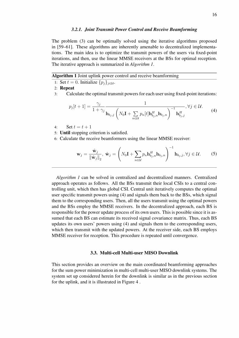
Algorithm 1 Joint uplink power control and receive beamforming1: Set t = 0. Initialize {pj}j∈U .2: Repeat3: Calculate the optimal transmit powers for each user using fixed-point iterations:
pj[t+ 1] =γj
1 + γj
1
hbj ,j
(N0I +
∑n∈U
pn[t]hHbj ,nhbj ,n
)−1hHbj ,j
, ∀j ∈ U .(4)
4: Set t = t+ 15: Until stopping criterion is satisfied.6: Calculate the receive beamformers using the linear MMSE receiver:
wj =wj
‖wj‖2, wj =
(N0I +
∑n∈U
pnhHbj ,n
hbj ,n
)−1hbj ,j, ∀j ∈ U . (5)
Algorithm 1 can be solved in centralized and decentralized manners. Centralizedapproach operates as follows. All the BSs transmit their local CSIs to a central con-trolling unit, which then has global CSI. Central unit iteratively computes the optimaluser specific transmit powers using (4) and signals them back to the BSs, which signalthem to the corresponding users. Then, all the users transmit using the optimal powersand the BSs employ the MMSE receivers. In the decentralized approach, each BS isresponsible for the power update process of its own users. This is possible since it is as-sumed that each BS can estimate its received signal covariance matrix. Thus, each BSupdates its own users’ powers using (4) and signals them to the corresponding users,which then transmit with the updated powers. At the receiver side, each BS employsMMSE receiver for reception. This procedure is repeated until convergence.
3.3. Multi-cell Multi-user MISO Downlink
This section provides an overview on the main coordinated beamforming approachesfor the sum power minimization in multi-cell multi-user MISO downlink systems. Thesystem set up considered herein for the downlink is similar as in the previous sectionfor the uplink, and it is illustrated in Figure 4 .
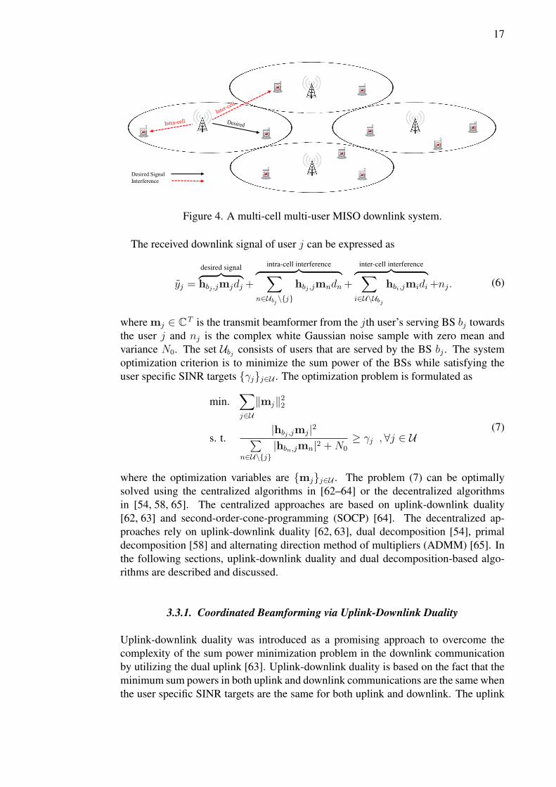
18
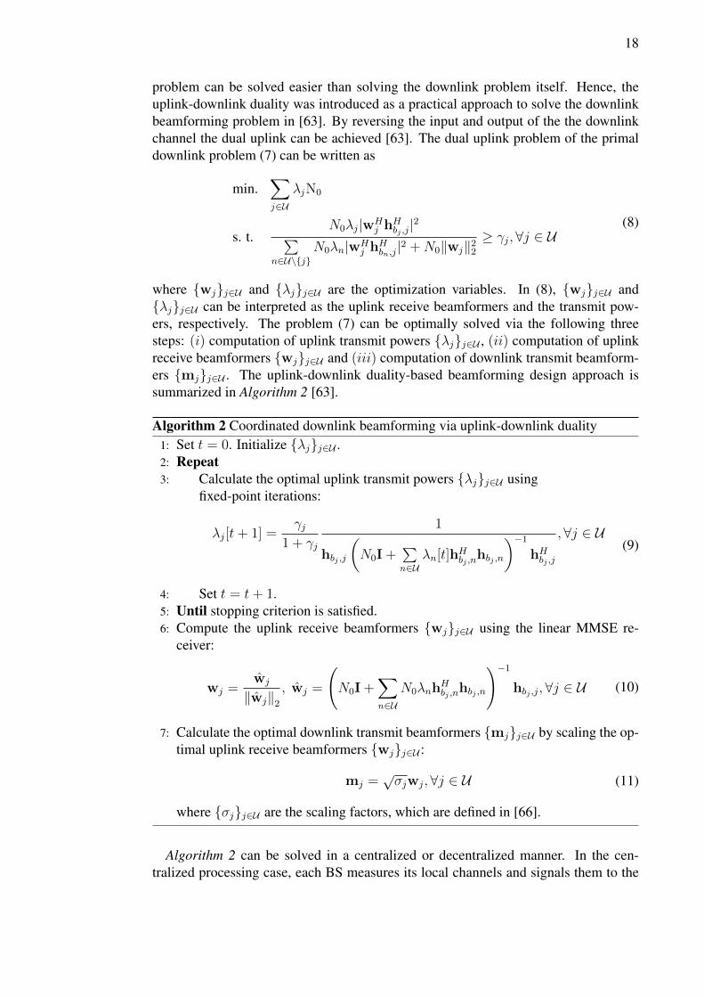
problem can be solved easier than solving the downlink problem itself. Hence, theuplink-downlink duality was introduced as a practical approach to solve the downlinkbeamforming problem in [63]. By reversing the input and output of the the downlinkchannel the dual uplink can be achieved [63]. The dual uplink problem of the primaldownlink problem (7) can be written as
min.∑j∈U
λjN0
s. t.N0λj|wH
j hHbj ,j|2∑
n∈U\{j}N0λn|wH
j hHbn,j|2 +N0‖wj‖22
≥ γj,∀j ∈ U(8)
where {wj}j∈U and {λj}j∈U are the optimization variables. In (8), {wj}j∈U and{λj}j∈U can be interpreted as the uplink receive beamformers and the transmit pow-ers, respectively. The problem (7) can be optimally solved via the following threesteps: (i) computation of uplink transmit powers {λj}j∈U , (ii) computation of uplinkreceive beamformers {wj}j∈U and (iii) computation of downlink transmit beamform-ers {mj}j∈U . The uplink-downlink duality-based beamforming design approach issummarized in Algorithm 2 [63].
Algorithm 2 Coordinated downlink beamforming via uplink-downlink duality1: Set t = 0. Initialize {λj}j∈U .2: Repeat3: Calculate the optimal uplink transmit powers {λj}j∈U using
fixed-point iterations:
λj[t+ 1] =γj
1 + γj
1
hbj ,j
(N0I +
∑n∈U
λn[t]hHbj ,nhbj ,n
)−1hHbj ,j
,∀j ∈ U(9)
4: Set t = t+ 1.5: Until stopping criterion is satisfied.6: Compute the uplink receive beamformers {wj}j∈U using the linear MMSE re-
ceiver:
wj =wj
‖wj‖2, wj =
(N0I +
∑n∈U
N0λnhHbj ,n
hbj ,n
)−1hbj ,j, ∀j ∈ U (10)
7: Calculate the optimal downlink transmit beamformers {mj}j∈U by scaling the op-timal uplink receive beamformers {wj}j∈U :
mj =√σjwj,∀j ∈ U (11)
where {σj}j∈U are the scaling factors, which are defined in [66].
Algorithm 2 can be solved in a centralized or decentralized manner. In the cen-tralized processing case, each BS measures its local channels and signals them to the
19
central controlling unit. This is a valid assumption in TDD mode where the downlinkchannels can be measured from the uplink due to the channel reciprocity. Central unitcomputes the optimal beamformers using the steps in Algorithm 2, and signal them tothe corresponding BSs. Then, each BS employs the optimal beamformers for the datatransmissions. In the decentralized processing case, the first implementation steps,i.e., computing the uplink powers and receive beamformers, are similar to that in Al-gorithm 1. On the top of that, Algorithm 2 employs a scaling process in order to adjustthe results of the dual-uplink problem for the downlink beamforming problem. Thiscan be performed also in a decentralized way through downlink per-user power updateas explained in [63].
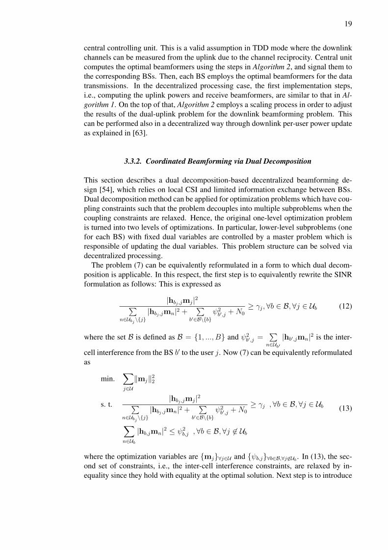
3.3.2. Coordinated Beamforming via Dual Decomposition
This section describes a dual decomposition-based decentralized beamforming de-sign [54], which relies on local CSI and limited information exchange between BSs.Dual decomposition method can be applied for optimization problems which have cou-pling constraints such that the problem decouples into multiple subproblems when thecoupling constraints are relaxed. Hence, the original one-level optimization problemis turned into two levels of optimizations. In particular, lower-level subproblems (onefor each BS) with fixed dual variables are controlled by a master problem which isresponsible of updating the dual variables. This problem structure can be solved viadecentralized processing.
The problem (7) can be equivalently reformulated in a form to which dual decom-position is applicable. In this respect, the first step is to equivalently rewrite the SINRformulation as follows: This is expressed as
|hbj ,jmj|2∑n∈Ubj \{j}
|hbj ,jmn|2 +∑
b′∈B\{b}ψ2b′,j +N0
≥ γj,∀b ∈ B,∀j ∈ Ub (12)
where the set B is defined as B = {1, ..., B} and ψ2b′,j =
∑n∈Ub′
|hb′,jmn|2 is the inter-
cell interference from the BS b′ to the user j. Now (7) can be equivalently reformulatedas
min.∑j∈U
‖mj‖22
s. t.|hbj ,jmj|2∑
n∈Ubj \{j}|hbj ,jmn|2 +
∑b′∈B\{b}
ψ2b′,j +N0
≥ γj ,∀b ∈ B,∀j ∈ Ub
∑n∈Ub
|hb,jmn|2 ≤ ψ2b,j ,∀b ∈ B,∀j 6∈ Ub
(13)
where the optimization variables are {mj}∀j∈U and {ψb,j}∀b∈B,∀j 6∈Ub . In (13), the sec-ond set of constraints, i.e., the inter-cell interference constraints, are relaxed by in-equality since they hold with equality at the optimal solution. Next step is to introduce
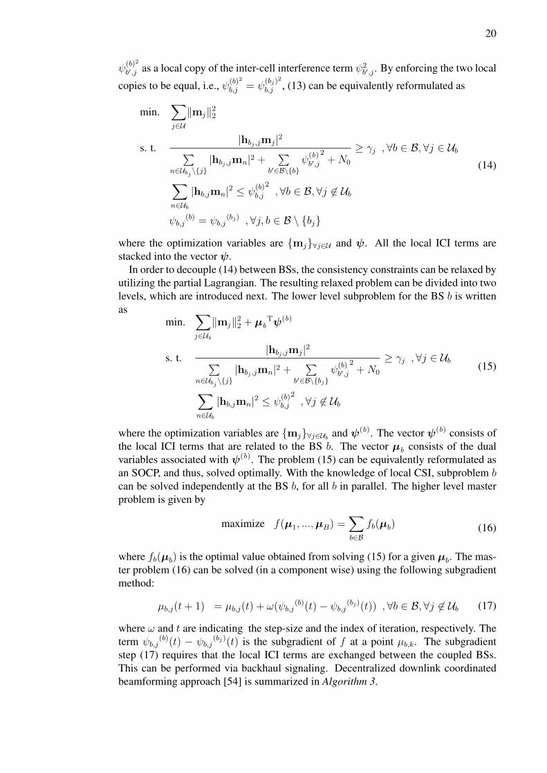
20
ψ(b)2
b′,j as a local copy of the inter-cell interference term ψ2b′,j . By enforcing the two local
copies to be equal, i.e., ψ(b)2
b,j = ψ(bj)
2
b,j , (13) can be equivalently reformulated as
min.∑j∈U
‖mj‖22
s. t.|hbj ,jmj|2∑
n∈Ubj \{j}|hbj ,jmn|2 +
∑b′∈B\{b}
ψ(b)b′,j
2+N0
≥ γj ,∀b ∈ B,∀j ∈ Ub
∑n∈Ub
|hb,jmn|2 ≤ ψ(b)b,j
2,∀b ∈ B,∀j 6∈ Ub
ψb,j(b) = ψb,j
(bj) ,∀j, b ∈ B \ {bj}
(14)
where the optimization variables are {mj}∀j∈U and ψ. All the local ICI terms arestacked into the vector ψ.
In order to decouple (14) between BSs, the consistency constraints can be relaxed byutilizing the partial Lagrangian. The resulting relaxed problem can be divided into twolevels, which are introduced next. The lower level subproblem for the BS b is writtenas
min.∑j∈Ub
‖mj‖22 + µbTψ(b)
s. t.|hbj ,jmj|2∑
n∈Ubj \{j}|hbj ,jmn|2 +
∑b′∈B\{bj}
ψ(b)b′,j
2+N0
≥ γj ,∀j ∈ Ub
∑n∈Ub
|hb,jmn|2 ≤ ψ(b)b,j
2,∀j 6∈ Ub
(15)
where the optimization variables are {mj}∀j∈Ub and ψ(b). The vector ψ(b) consists ofthe local ICI terms that are related to the BS b. The vector µb consists of the dualvariables associated with ψ(b). The problem (15) can be equivalently reformulated asan SOCP, and thus, solved optimally. With the knowledge of local CSI, subproblem bcan be solved independently at the BS b, for all b in parallel. The higher level masterproblem is given by
maximize f(µ1, ...,µB) =∑b∈B
fb(µb) (16)
where fb(µb) is the optimal value obtained from solving (15) for a given µb. The mas-ter problem (16) can be solved (in a component wise) using the following subgradientmethod:
µb,j(t+ 1) = µb,j(t) + ω(ψb,j(b)(t)− ψb,j(bj)(t)) ,∀b ∈ B,∀j 6∈ Ub (17)
where ω and t are indicating the step-size and the index of iteration, respectively. Theterm ψb,j
(b)(t) − ψb,j(bj)(t) is the subgradient of f at a point µb,k. The subgradient
step (17) requires that the local ICI terms are exchanged between the coupled BSs.This can be performed via backhaul signaling. Decentralized downlink coordinatedbeamforming approach [54] is summarized in Algorithm 3.
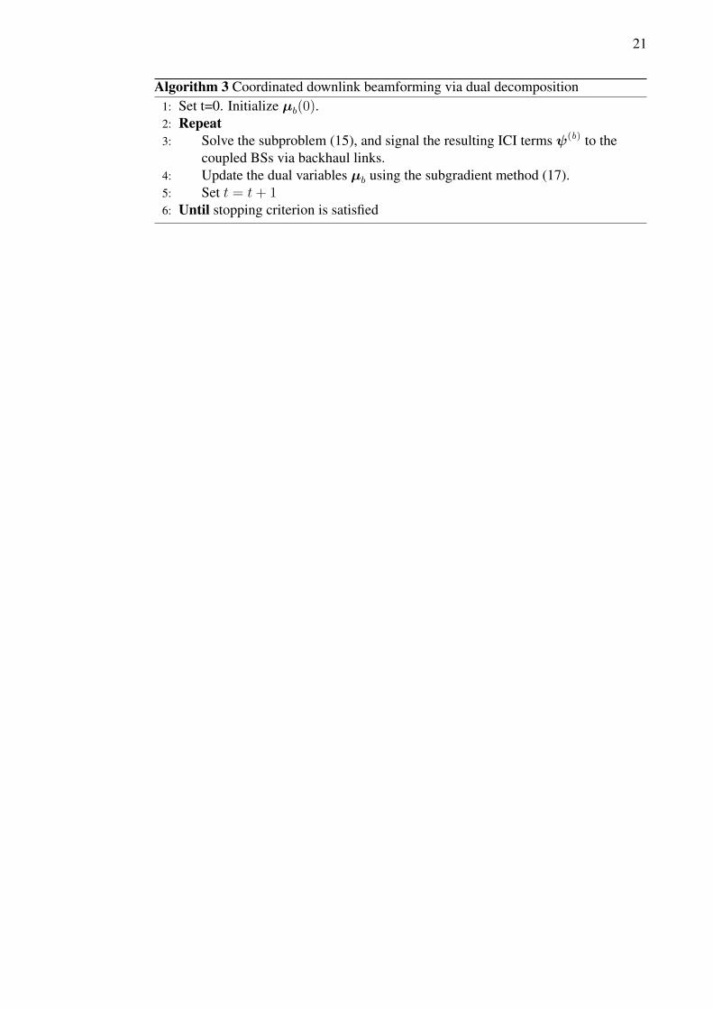
21
Algorithm 3 Coordinated downlink beamforming via dual decomposition1: Set t=0. Initialize µb(0).2: Repeat3: Solve the subproblem (15), and signal the resulting ICI terms ψ(b) to the
coupled BSs via backhaul links.4: Update the dual variables µb using the subgradient method (17).5: Set t = t+ 16: Until stopping criterion is satisfied
24
be equal for uplink and downlink phases for both cellular and D2D communications.Thus, the overall problem can be separated between uplink and downlink. The result-ing uplink problem can be written as
min. pcu + pdtx
s. t. log2
(1 +
pcu|wHcuh
Hcu|2
pdtx|wHcuh
Hdtx|2 +N0
)≥ Rcu
log2
(1 +
pdtx|gdtx,drx|2
pcu|gcu,drx|2 +N0
)≥ Rdrx
(23)
where the optimization variables are pcu, pdtx and wcu. Note that the receive beam-forming vector is normalized, i.e., ‖wcu‖2 = 1.. The fixed values Rcu and Rdrx arethe minimum rate targets for the cellular user and D2D pair, respectively. Note thatthe rate constraints in (23) can be equivalently mapped into the SINR constraints. Theresulting equivalent uplink optimization problem is given by
min. pcu + pdtx
s. t.pcu|wH
cuhHcu|2
pdtx|wHcuh
Hdtx|2 +N0
≥ γcu
p2|gdtx,drx|2
pcu|gcu,drx|2 +N0
≥ γdrx
(24)
where the optimization variables are the same as in (23), and γcu = 2Rcu − 1 andγdrx = 2Rdrx − 1 are the fixed SINR targets.
Similarly, the downlink sum power minimization problem is expressed as
min. ‖mcu‖22 + pdtx
s. t.|hcumcu|2
pdtx|gdtx,cu|2 +N0
≥ γcu
pdtx|gdtx,drx|2
|hdrxmcu|2 +N0
≥ γdrx
(25)
where the optimization variables are pdtx and mcu.
4.2. Solution for Uplink Communications
In this section, joint power control and receive beamforming algorithm is proposed tooptimally solve the uplink power minimization problem (24). The proposed algorithmextends the ideas from the conventional cellular communications described in sec-tion 3.2 to the underlaying D2D communication system. After setting the Lagrangianof (24) to zero (w.r.t. wcu) and some rearranging, similar to that in [63], the optimalpowers of the cellular user and D2D transmitter can be iteratively calculated via thefollowing fixed-point iterations
pcu[t+ 1] =γcu
hcu (N0I + pdtx[t]hHdtxhdtx)−1
hHcu(26)
25
pdtx[t+ 1] =γdrx
gdtx,drx(N0 + pcu[t]gHcu,drxgcu,drx
)−1gHdtx,drx
. (27)
The optimal receive beamformer at the BS can be calculated by using the (scaled)linear MMSE receiver:
wcu =wcu
‖wcu‖2, wcu =
(N0I + pdtxh
Hdtxhdtx
)−1hcu. (28)
The proposed uplink power control and receive beamforming approach is summarizedin Algorithm 4. The implementation requirements of Algorithm 4 are discussed insection 4.4.
Algorithm 4 Joint uplink power control and receive beamforming1: Set t = 0. Initialize pcu(0) and pdtx(0)2: Repeat3: Calculate the transmit powers pcu(t+ 1) and pdtx(t+ 1) using (26)
and (27), respectively.4: Set t = t+ 15: Until stopping criterion is satisfied.6: Calculated the receive beamformer wcu using (28).
4.3. Solutions for Downlink Communications
4.3.1. Centralized SOCP-based Algorithm
In this section, an optimal centralized approach is proposed to solve the downlinksum power minimization problem (25). By denoting pdtx =
√pdtx, and following the
similar procedure as in [64], (25) can be equivalently reformulated as the followingconvex SOCP:
min. q
s. t.√
1
γcuhcumcu ≥
∥∥∥∥pdtxgdtx,cu√N0
∥∥∥∥2√
1
γdtxpdtxgdtx,drx ≥
∥∥∥∥hdtxmcu√N0
∥∥∥∥2∥∥∥∥mcu
pdtx
∥∥∥∥2
≤ q
(29)
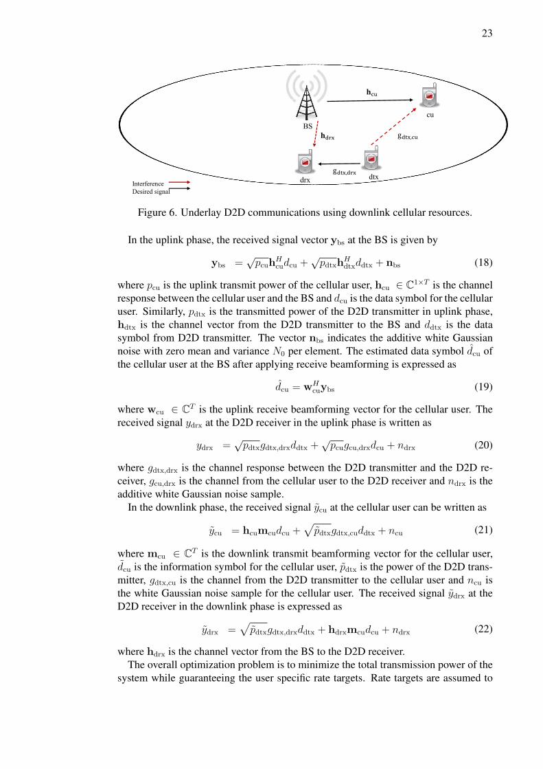
where the optimization variables are q, pdtx, and mcu. The problem (29) can be solvedvia centralized processing if global CSI is available at the BS. In other words, the BSneeds to know all the channels depicted in Figure 6. Assuming TDD mode, the BS canacquire its own local channels from the uplink phase. However, the channels from theD2D transmitter to the D2D receiver and to the cellular user need to be delivered to theBS via over-the-air signaling.
26
4.3.2. Decentralized Dual Decomposition-based Algorithm
In this section, a decentralized solution is presented for the sum power minimizationproblem (25). The proposed approach extends the coordinated beamforming approachfrom cellular networks, as described in section 3.3.2 and in [54], to the underlayingD2D communication system. The idea is to use dual decomposition to turn the originalone-level optimization problem (25) into two levels of optimizations, i.e., a masterproblem and several subproblems with fixed dual variables. In particular, the masterproblem is responsible for updating the dual variables and each dual variable dependentsubproblem is to be solved accordingly. This two-level optimization can be solvedat the BS via decentralized processing with the aid of limited over-the-air signalingbetween the transmitters (i.e., the BS and D2D transmitter). In order to apply dualdecomposition method, (25) needs to be reformulated. The first step is to equivalentlyrewrite the SINR constraints as
|hcumcu|2
ψ2dtx,cu +N0
≥ γcu (30)
pdtx|gdtx,drx|2
ψ2bs,drx +N0
≥ γdrx (31)
where ψ2dtx,cu = pdtx|gdtx,cu|2 denotes the interference from the D2D transmitter to the
cellular user and ψ2bs,drx = |hdrxmcu|2 denotes the interference from the BS to the D2D
receiver. Now, the original downlink optimization problem (25) can be equivalentlyrewritten as
min. ‖mcu‖22 + pdtx
s. t.|hcumcu|2
ψ2dtx,cu +N0
≥ γcu
pdtx|gdtx,drx|2
ψ2bs,drx +N0
≥ γdrx
pdtx|gdtx,cu|2 ≤ ψ2dtx,cu
|hdrxmcu|2 ≤ ψ2bs,drx
(32)
where the optimization variables are mcu, pdtx, ψdtx,cu and ψbs,drx. The problem (32)is equivalent to (25) since the third and fourth constraints hold with equality at the op-timal solution. Now (32) is coupled between the transmitters by the interference termsψdtx,cu and ψbs,drx. By fixing the interference terms, (32) would decouple, and thus,each transmitter (i.e., the BS and D2D transmitter) could minimize its transmit powerseparately. Next step is to introduce transmitter specific (i.e., local) auxiliary variablesand additional equality constraints such that the coupling in the SINR constraints istransferred to the added equality constraints. After this reformulation, equality con-straints can be decoupled via standard dual decomposition method. The aforemen-tioned auxiliary variables are the transmitter specific copies of ψdtx,cu and ψbs,drx, andthey are denoted by ψbs
dtx,cu, ψdtxdtx,cu and ψbs
bs,drx, ψdtxbs,drx. The additional equality con-
27
straints enforce the two transmitter specific copies to be equal, i.e., ψbsdtx,cu = ψdtx
dtx,cu
and ψbsbs,drx = ψdtx
bs,drx. Now (32) can be equivalently reformulated as
min. ‖mcu‖22 + pdtx
s. t.|hcumcu|2
ψbsdtx,cu
2+N0
≥ γcu
pdtx|gdtx,drx|2
ψdtxbs,drx
2+N0
≥ γdrx
pdtx|gdtx,cu|2 ≤ ψdtxdtx,cu
2
|hdrxmcu|2 ≤ ψbsbs,drx
2
ψdtxdtx,cu = ψbs
dtx,cu
ψbsbs,drx = ψdtx
bs,drx
(33)
where the optimization variables are pdtx, mcu, ψdtxdtx,cu, ψbs
dtx,cu, ψbsbs,drx and ψdtx
bs,drx.In (33), the coupling is only involved in the equality constraints since the objectiveand inequality constraints can be separated between the transmitters. To achieve adistributed algorithm, a standard dual decomposition method is applied next. First, wetake the partial Lagrangian by relaxing the consistency constraints as follows:
L(mcu, pdtx, ψbsbs,drx, ψ
dtxbs,drx, ψ
dtxdtx,cu, ψ
bsdtx,cu, µbs,drx, µdtx,cu) =
‖mcu‖22 + pdtx + µbs,drx(ψbsbs,drx − ψdtx
bs,drx) + µdtx,cu(ψdtxdtx,cu − ψbs
dtx,cu)(34)
where µbs,drx and µdtx,cu are the dual variables associated with the equality constraints.The dual function is formulated as
g(µbs,µdtx) = gcu(µbs) + gdtx(µdtx) (35)
where gcu(µb) and gdtx(µdtx) are defined as
gcu(µbs) = infmcu,ψ
bs‖mcu‖22 + µbs
Tψbs(36)
gdtx(µdtx) = infpdtx,ψ
dtxpdtx + µdtx
Tψdtx. (37)
The vectors are defined as µb = [µbs,drx,−µdtx,cu]T , µdtx = [−µbs,drx, µdtx,cu]T ,ψbs =[ψbs
bs,drx, ψbsdtx,cu]T and ψdtx = [ψdtx
bs,drx, ψdtxdtx,cu]T .
Finally, the lower level subproblems for the BS and D2D transmitter can be formu-lated as
min. ‖mcu‖22 + µbsTψbs
s. t.|hcumcu|2
ψbs2dtx,cu
+N0 ≥ γcu
|hbs,drxmcu|2 ≤ ψbsbs,drx
2
(38)
andmin. pdtx + µdtx
Tψdtx
s. t.pdtx|gdtx,drx|2
ψdtxbs,drx
2+N0
≥ γdrx
pdtx|gdtx,cu|2 ≤ ψdtxdtx,cu
2
(39)
28
where mcu,ψbs are the optimization variables in (38) and pdtx and ψdtx are the opti-
mization variables in (39). The subproblems (38) and (39) can be written in epigraphforms as follows:
min. zbs
s. t. ‖mcu‖22 + µbsTψbs ≤ zbs
|hcumcu|2
ψbsdtx,cu
2+N0
≥ γcu
|hdrxmcu|2 ≤ ψbsbs,drx
2
(40)
andmin. zdtx
s. t. pdtx + µdtxTψdtx ≤ zdtx
pdtx|gdtx,drx|2
ψdtxbs,drx
2+N0
≥ γdrx
pdtx|gdtx,cu|2 ≤ ψdtxdtx,cu
2
(41)
where the optimization variables for (40) are mcu, ψbs, and zbs. In (41), the optimiza-tion variables are pdtx, ψdtx, and zdtx. By denoting pdtx =
√pdtx and following the
similar procedure as in [54], the optimization problems (40) and (41) can be casted asthe following SOCPs:
min. zbs
s. t.
(1− µbsTψbs + zbs)/2
(1 + µbsTψbs − zbs)/2mcu
�SOC0
√
1 + 1γcu
hcumcu
ψbsdtx,cu√N0
�SOC0
[ψbsbs,drx
mcuHhdrx
H
]�SOC0
(42)
andmin. zdtx
s. t.
(1− µdtxTψdtx + zdtx)/2
(1 + µdtxTψdtx − zdtx)/2pdtx
�SOC0
√
1 + 1γdtx
pdtxgdtx,drx
ψdtxbs,drx√N0
�SOC0
[ψdtxdtx,cu
pdtxgdtx,cu
]�SOC0
(43)
29
where the optimization variables are mcu,ψbs, and zbs for (42), and pdtx,ψdtx, and zdtxfor (43). The master problem for the dual decomposition is expressed as
maximizeµbs,µdtx
g(µbs,µdtx). (44)
The sub-gradient method can be used to solve the master problem. Thus, (44) can besolved iteratively by using the following sub-gradient updates:
µbs,drx(t+ 1) = µbs,drx(t) + ω(ψdtxdtx,cu − ψbs
dtx,cu)
µdtx,cu(t+ 1) = µdtx,cu(t) + ω(ψbsbs,drx − ψdtx
bs,drx)(45)
where t is the iteration index and ω is a positive step-size. To find a feasible trans-mission solution at any iteration, (43) and (42) can be solved with the following fixedaverage values of interference terms
ψdtx,cu(t) =1
2(ψbs
dtx,cu(t) + ψdtxdtx,cu(t))
ψbs,drx(t) =1
2(ψdtx
bs,drx(t) + ψbsbs,drx(t)).
(46)
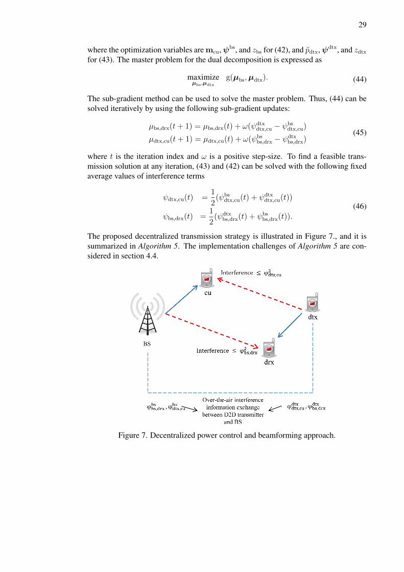
The proposed decentralized transmission strategy is illustrated in Figure 7., and it issummarized in Algorithm 5. The implementation challenges of Algorithm 5 are con-sidered in section 4.4.
Figure 7. Decentralized power control and beamforming approach.
30
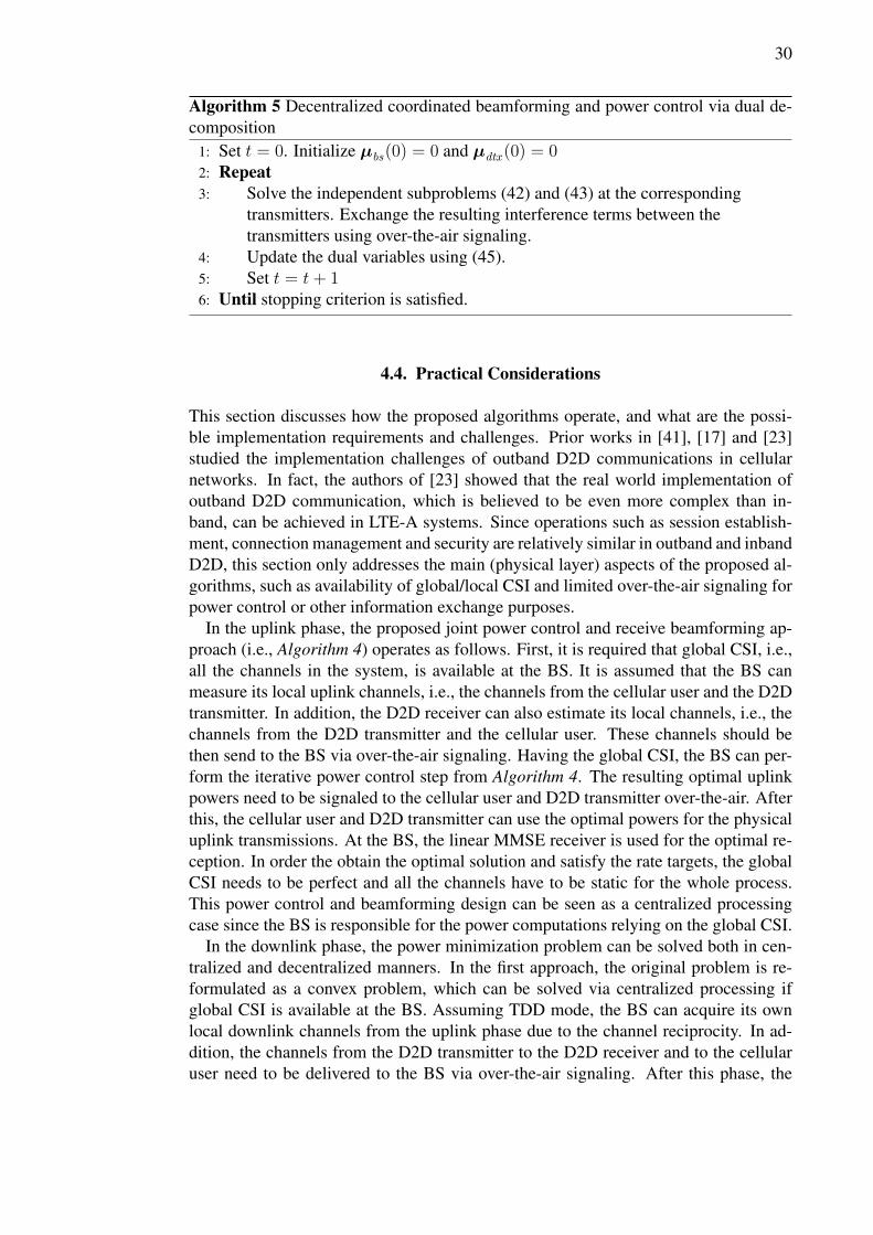
Algorithm 5 Decentralized coordinated beamforming and power control via dual de-composition
1: Set t = 0. Initialize µbs(0) = 0 and µdtx (0) = 02: Repeat3: Solve the independent subproblems (42) and (43) at the corresponding
transmitters. Exchange the resulting interference terms between thetransmitters using over-the-air signaling.
4: Update the dual variables using (45).5: Set t = t+ 16: Until stopping criterion is satisfied.
4.4. Practical Considerations
This section discusses how the proposed algorithms operate, and what are the possi-ble implementation requirements and challenges. Prior works in [41], [17] and [23]studied the implementation challenges of outband D2D communications in cellularnetworks. In fact, the authors of [23] showed that the real world implementation ofoutband D2D communication, which is believed to be even more complex than in-band, can be achieved in LTE-A systems. Since operations such as session establish-ment, connection management and security are relatively similar in outband and inbandD2D, this section only addresses the main (physical layer) aspects of the proposed al-gorithms, such as availability of global/local CSI and limited over-the-air signaling forpower control or other information exchange purposes.
In the uplink phase, the proposed joint power control and receive beamforming ap-proach (i.e., Algorithm 4) operates as follows. First, it is required that global CSI, i.e.,all the channels in the system, is available at the BS. It is assumed that the BS canmeasure its local uplink channels, i.e., the channels from the cellular user and the D2Dtransmitter. In addition, the D2D receiver can also estimate its local channels, i.e., thechannels from the D2D transmitter and the cellular user. These channels should bethen send to the BS via over-the-air signaling. Having the global CSI, the BS can per-form the iterative power control step from Algorithm 4. The resulting optimal uplinkpowers need to be signaled to the cellular user and D2D transmitter over-the-air. Afterthis, the cellular user and D2D transmitter can use the optimal powers for the physicaluplink transmissions. At the BS, the linear MMSE receiver is used for the optimal re-ception. In order the obtain the optimal solution and satisfy the rate targets, the globalCSI needs to be perfect and all the channels have to be static for the whole process.This power control and beamforming design can be seen as a centralized processingcase since the BS is responsible for the power computations relying on the global CSI.
In the downlink phase, the power minimization problem can be solved both in cen-tralized and decentralized manners. In the first approach, the original problem is re-formulated as a convex problem, which can be solved via centralized processing ifglobal CSI is available at the BS. Assuming TDD mode, the BS can acquire its ownlocal downlink channels from the uplink phase due to the channel reciprocity. In ad-dition, the channels from the D2D transmitter to the D2D receiver and to the cellularuser need to be delivered to the BS via over-the-air signaling. After this phase, the
31
BS can compute the optimal transmit beamformer for the cellular user and the opti-mal power for the D2D transmitter. Over-the-air signaling is again used to deliver thepower information to the D2D transmitter. Finally, the BS and the D2D transmittercan physically transmit with optimal parameters. Similarly as in the uplink case, theglobal CSI needs to be perfect and all the channels have to be static in order to achieveoptimal performance with rate targets satisfied.
In the second approach, the dual decomposition is first used to reformulate the orig-inal problem in a form where a decentralized implementation is possible. In this case,the BS and D2D transmitter can be seen as separate entities, both of which are respon-sible of serving their own users independently. Thus, both the BS and D2D transmitterrely only on the local CSI and limited information exchange between them via over-the-air signaling. Local CSI can be acquired from the uplink measurements (assumingthat also D2D receiver is sometimes in transmitting mode). At each iteration of theAlgorithm 5, limited amount of information, i.e., the coupled ICI terms, is exchangedbetween the BS and D2D transmitter. If the local CSI is perfect and all the channelsremain static, Algorithm 5 will converge to the optimal solution. Note that feasibleiterates, where the rate targets are satisfied, can also be achieved during the conver-gence process. Hence, to avoid long delays and to reduce signaling/computationalload, Algorithm 5 can be stopped at intermediate iterations. This comes at the costof (somewhat) sub-optimal performance. It is worth noting that in this simple sys-tem model case, where there are only few single antenna users, centralized processingmay be a better choice. However, for the larger multi-cell multiuser systems, decen-tralized implementation might be beneficial by potentially reducing the amount of theexchanged control information between the BS and D2D transmitter as compared withthe centralized case. Furthermore, the proposed decentralized approach can operateeven if the exchanged information between the transmitters is outdated.
32
5. NUMERICAL EVALUATION
In this chapter, the performance of the algorithms proposed in the previous chapter arenumerically evaluated. The chapter is arranged such that, first, the simulation modeland parameters are introduced. Then, the performance of the D2D communicationapproach is numerically compared with the pure cellular case.
5.1. Simulation Model and Parameters
The simulation model consists of a single cell with a BS serving a single cellularuser and an underlaying D2D user pair. The BS is equipped with T = 4 antennas,whereas each user has a single antenna. In all simulation scenarios, the D2D pair andthe cellular user have fixed distances from the BS, i.e., the users are located on thecell-edge, whereas the channels between the BS and users are simulated by applyinga simple distance dependent pathloss model. The channel between the BS and thecellular user is expressed as
hcu =
√(R
r0
)−αhcu (47)
where R is the cell radius, α is the pathloss exponent and r0 is the far field referencedistance. In the simulations, macro and small cells are modeled by setting the cellradiusR to 400 m and 50 m, respectively. Furthermore, the channel vector hcu consistsof i.i.d. complex random elements that are generated from Gaussian distribution, eachwith zero mean and unit variance. The same model is used to generate the channelsfrom the BS to the D2D transmitter and receiver, i.e., hdtx and hdrtx, respectively.Moreover, the similar pathloss model as in (47) is also considered for the channelsbetween the cellular and D2D users. Precisely, the channel from the D2D transmitterto the D2D receiver is given by
gdtx,drx =
√(Ldtx,drx
l0
)−αgdtx,drx (48)
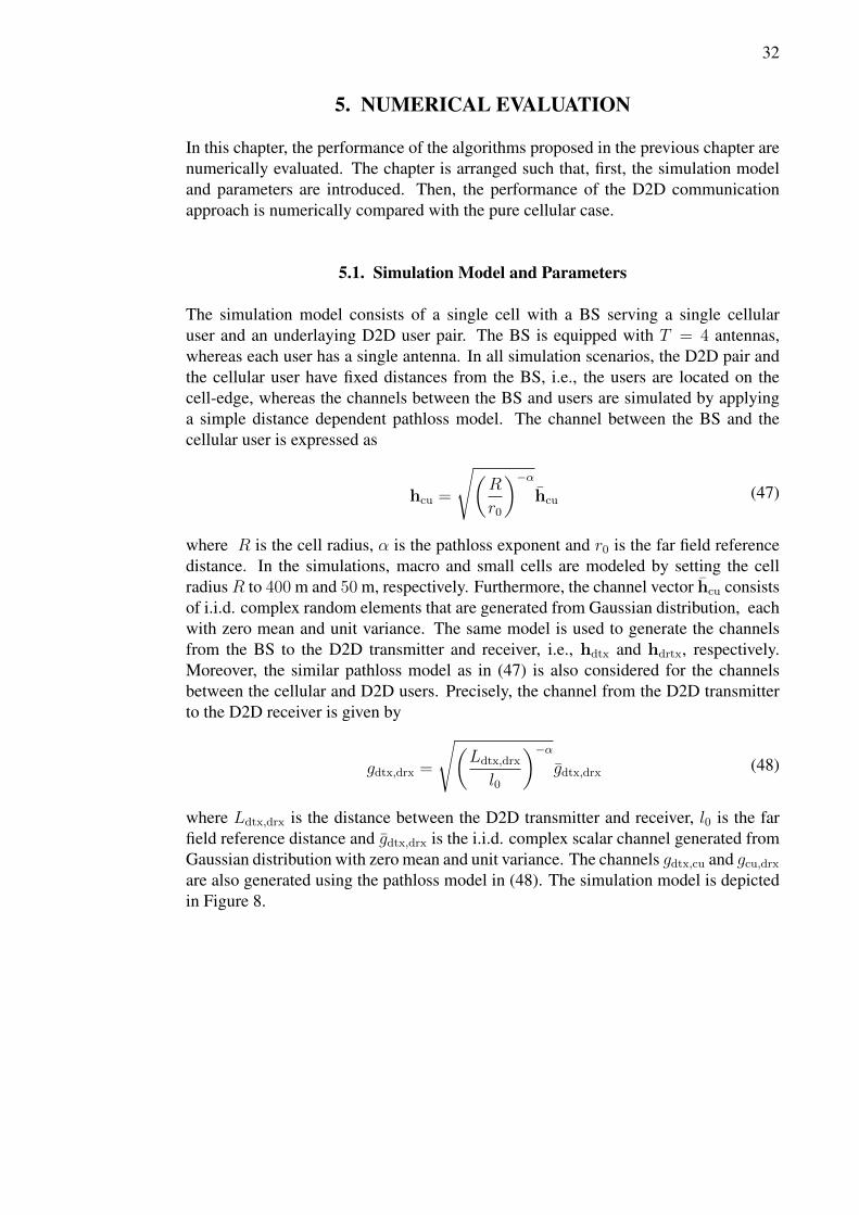
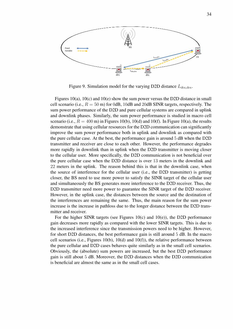
where Ldtx,drx is the distance between the D2D transmitter and receiver, l0 is the farfield reference distance and gdtx,drx is the i.i.d. complex scalar channel generated fromGaussian distribution with zero mean and unit variance. The channels gdtx,cu and gcu,drxare also generated using the pathloss model in (48). The simulation model is depictedin Figure 8.
35
0 5 10 15 20 25−115
−110
−105
−100
−95
−90
Sum
Pow
er [d
Bm
]
D2D Distance, Ldtx,drx
[m]
g = 0dB, R = 50m, Lcu,drx
= 27m
D2D downlinkD2D uplinkCellular uplinkCellular downlink
(a)
0 5 10 15 20 25−80
−75
−70
−65
−60
−55
−50
−45
−40
Sum
Pow
er [d
Bm
]
D2D Distance, Ldtx,drx
[m]
g = 0dB, R = 400m, Lcu,drx
= 27m
D2D downlinkD2D uplinkCellular uplinkCellular downlink
(b)
0 5 10 15 20 25−105
−100
−95
−90
−85
−80
Sum
Pow
er [d
Bm
]
D2D Distance, Ldtx,drx
[m]
g = 10dB, R = 50m, Lcu,drx
= 27m
D2D downlinkD2D uplinkCellular uplinkCellular downlink
(c)
0 5 10 15 20 25−70
−65
−60
−55
−50
−45
−40
−35
−30
Sum
Pow
er [d
Bm
]
D2D Distance, Ldtx,drx
[m]
g = 10dB, R = 400m, Lcu,drx
= 27m
D2D downlinkD2D uplinkCellular uplinkCellular downlink
(d)
0 5 10 15 20 25−95
−90
−85
−80
−75
−70
−65
−60
Sum
Pow
er [d
Bm
]
D2D Distance, Ldtx,drx
[m]
g = 20dB, R = 50m, Lcu,drx
= 27m
D2D downlinkD2D uplinkCellular uplinkCellular downlink
(e)
0 5 10 15 20 25−60
−55
−50
−45
−40
−35
−30
−25
−20
−15
−10
Sum
Pow
er [d
Bm
]
D2D Distance, Ldtx,drx
[m]
g = 20dB, R = 400m, Lcu,drx
= 27m
D2D downlinkD2D uplinkCellular uplinkCellular downlink
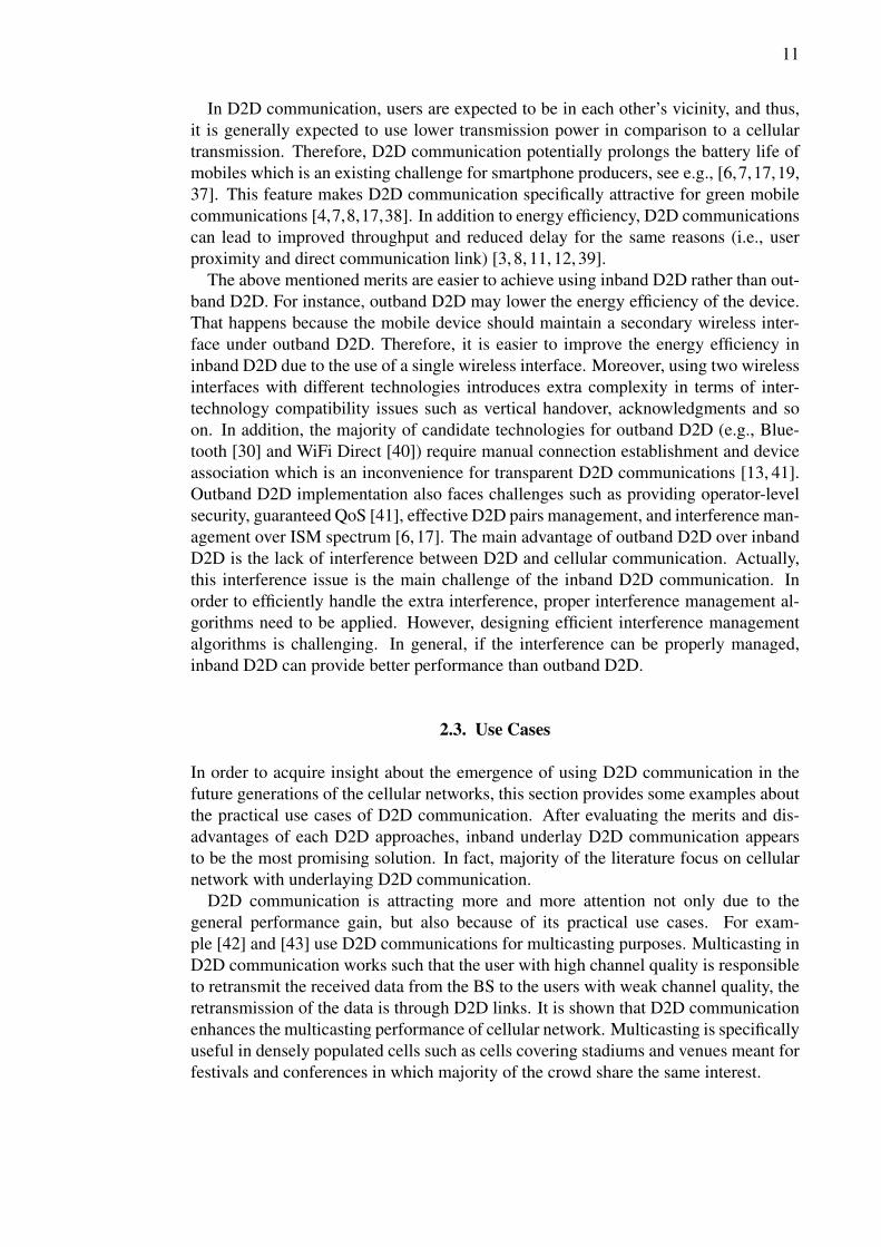
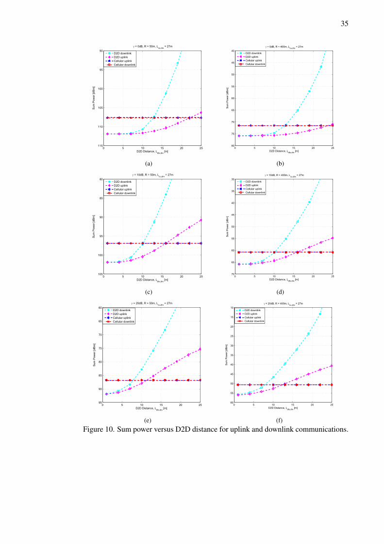
(f)Figure 10. Sum power versus D2D distance for uplink and downlink communications.
36
0 5 10 15 20 25−180
−160
−140
−120
−100
−80
−60
Pow
er [d
Bm
]
D2D Distance, Ldtx,drx
[m]
γ= 0dB, R = 50m, Lcu,drx
= 27m
p
dtx, D2D uplink
pcu
, D2D uplink
p∼dtx
, D2D downlink
p∼cu
, D2D downlink
(a)
0 5 10 15 20 25−180
−160
−140
−120
−100
−80
−60
−40
−20
Pow
er
[dB
m]
D2D Distance, Ldtx,drx
[m]
γ = 0dB, R = 400m, Lcu,drx
= 27m
p
dtx, D2D uplink
pcu
, D2D uplink
p∼
dtx, D2D downlink
p∼
cu, D2D downlink
(b)
0 5 10 15 20 25−160
−140
−120
−100
−80
−60
−40
Pow
er [d
Bm
]
D2D Distance, Ldtx,drx
[m]
γ = 10dB, R = 50m, Lcu,drx
= 27m
p
dtx, D2D uplink
pcu
, D2D uplink
p∼
dtx, D2D downlink
p∼
cu, D2D downlink
(c)
0 5 10 15 20 25−160
−140
−120
−100
−80
−60
−40
−20
0
Pow
er [d
Bm
]
D2D Distance, Ldtx,drx
[m]
γ = 10dB, R = 400m, Lcu,drx
= 27m
p
dtx, D2D uplink
pcu
, D2D uplink
p∼dtx
, D2D downlink
p∼cu
, D2D downlink
(d)
0 5 10 15 20 25−160
−140
−120
−100
−80
−60
−40
−20
Po
we
r [d
Bm
]
D2D Distance, Ldtx,drx
[m]
γ = 20dB, R = 50m, Lcu,drx
= 27m
p
dtx, D2D uplink
pcu
, D2D uplink
p∼
dtx, D2D downlink
p∼
cu, D2D downlink
(e)
0 5 10 15 20 25−160
−140
−120
−100
−80
−60
−40
−20
0
20
Pow
er [d
Bm
]
D2D Distance, Ldtx,drx
[m]
γ = 20dB, R = 400m, Lcu,drx
= 27m
p
dtx, D2D uplink
pcu
, D2D uplink
p∼dtx
, D2D downlink
p∼cu
, D2D downlink
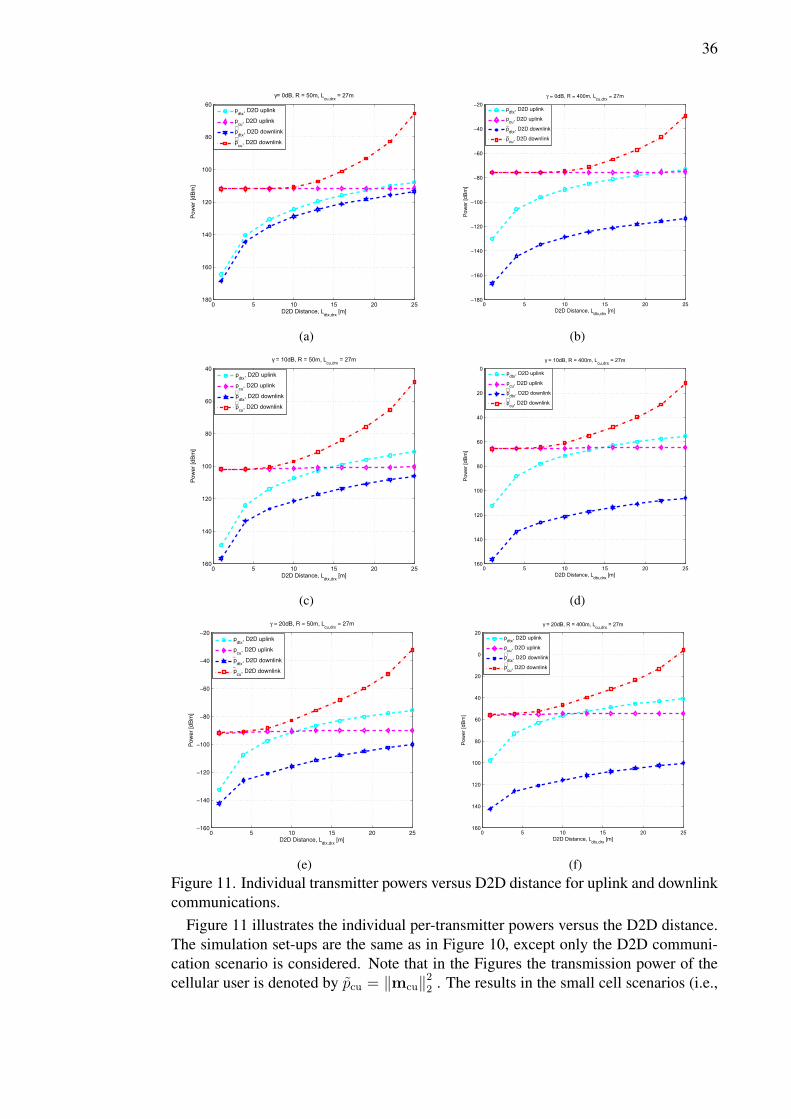
(f)Figure 11. Individual transmitter powers versus D2D distance for uplink and downlinkcommunications.
Figure 11 illustrates the individual per-transmitter powers versus the D2D distance.The simulation set-ups are the same as in Figure 10, except only the D2D communi-cation scenario is considered. Note that in the Figures the transmission power of thecellular user is denoted by pcu = ‖mcu‖22 . The results in the small cell scenarios (i.e.,
38
−50 −40 −30 −20 −10 0 10 20 30 40 50−115
−110
−105
−100
−95
−90
−85
−80
−75
−70
−65
Sum
Pow
er [d
Bm
]
cu−drx Distance, Lcu,drx
[m]
g = 0dB, R = 50m, Ldtx,drx
= 10m
D2D downlinkD2D uplinkCellular uplinkCellular downlink
(a)
−50 −40 −30 −20 −10 0 10 20 30 40 50−110
−100
−90
−80
−70
−60
−50
−40
Sum
Pow
er [d
Bm
]
cu−drx Distance, Lcu,drx
[m]
g = 0dB, R = 400m, Ldtx,drx
= 10m
D2D downlinkD2D uplinkCellular uplinkCellular downlink
(b)
−50 −40 −30 −20 −10 0 10 20 30 40 50
−100
−90
−80
−70
−60
−50
−40
Sum
Pow
er [d
Bm
]
cu−drx Distance, Lcu,drx
[m]
g = 10dB, R = 50m, Ldtx,drx
= 10m
D2D downlinkD2D uplinkCellular uplinkCellular downlink
(c)
−50 −40 −30 −20 −10 0 10 20 30 40 50−70
−60
−50
−40
−30
−20
−10
Sum
Pow
er [d
Bm
]
cu−drx Distance, Lcu,drx
[m]
g = 10dB, R = 400m, Ldtx,drx
= 10m
D2D downlinkD2D uplinkCellular uplinkCellular downlink
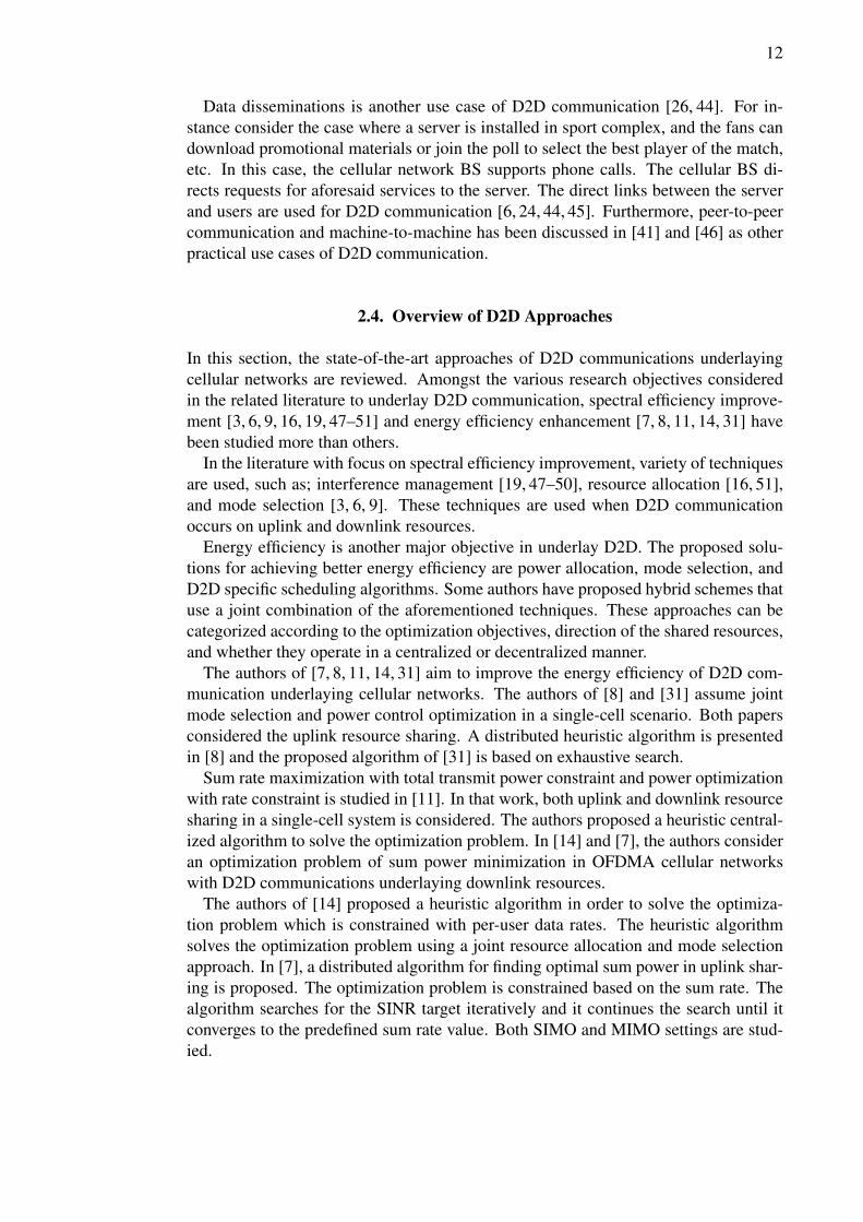
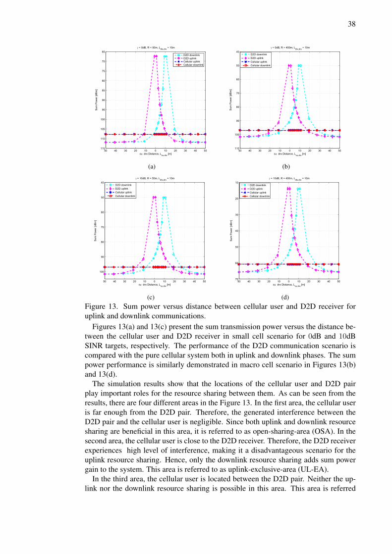
(d)Figure 13. Sum power versus distance between cellular user and D2D receiver foruplink and downlink communications.
Figures 13(a) and 13(c) present the sum transmission power versus the distance be-tween the cellular user and D2D receiver in small cell scenario for 0dB and 10dBSINR targets, respectively. The performance of the D2D communication scenario iscompared with the pure cellular system both in uplink and downlink phases. The sumpower performance is similarly demonstrated in macro cell scenario in Figures 13(b)and 13(d).
The simulation results show that the locations of the cellular user and D2D pairplay important roles for the resource sharing between them. As can be seen from theresults, there are four different areas in the Figure 13. In the first area, the cellular useris far enough from the D2D pair. Therefore, the generated interference between theD2D pair and the cellular user is negligible. Since both uplink and downlink resourcesharing are beneficial in this area, it is referred to as open-sharing-area (OSA). In thesecond area, the cellular user is close to the D2D receiver. Therefore, the D2D receiverexperiences high level of interference, making it a disadvantageous scenario for theuplink resource sharing. Hence, only the downlink resource sharing adds sum powergain to the system. This area is referred to as uplink-exclusive-area (UL-EA).
In the third area, the cellular user is located between the D2D pair. Neither the up-link nor the downlink resource sharing is possible in this area. This area is referred
39
to as D2D-exclusive-area (DEA). In the fourth area, the cellular user is moving awayfrom the D2D transmitter. In this area, the uplink resource sharing adds sum powergain to the system. Nevertheless, the downlink resource sharing is not advantageousbecause the source of interference for the cellular user (i.e., the D2D transmitter) isclose, making it a worst case scenario for the downlink resource sharing. The afore-mentioned area is defined as downlink-exclusive-area (DL-EA). Table 2 summarizesthe characteristics of four D2D resource sharing areas.
Table 2. Characteristics of four D2D resource sharing areas.Region D2D Feasibility Uplink Underlay Downlink Underlay
D2D-exclusive-area x x xUplink-exclusive-area X x X
Downlink-exclusive-area X X xOpen-sharing-area X X X
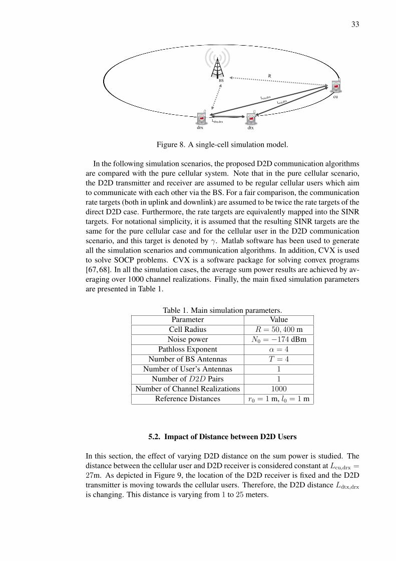
It can be observed that the level of the SINR targets has an impact on the sizes ofthe four defined areas. The higher the targets, the smaller the areas where the D2Dcommunication is beneficial. Moreover, the results also imply that the larger cell sizeincreases the sum power levels, but does not have much of an effect to the sizes of thedefined areas.
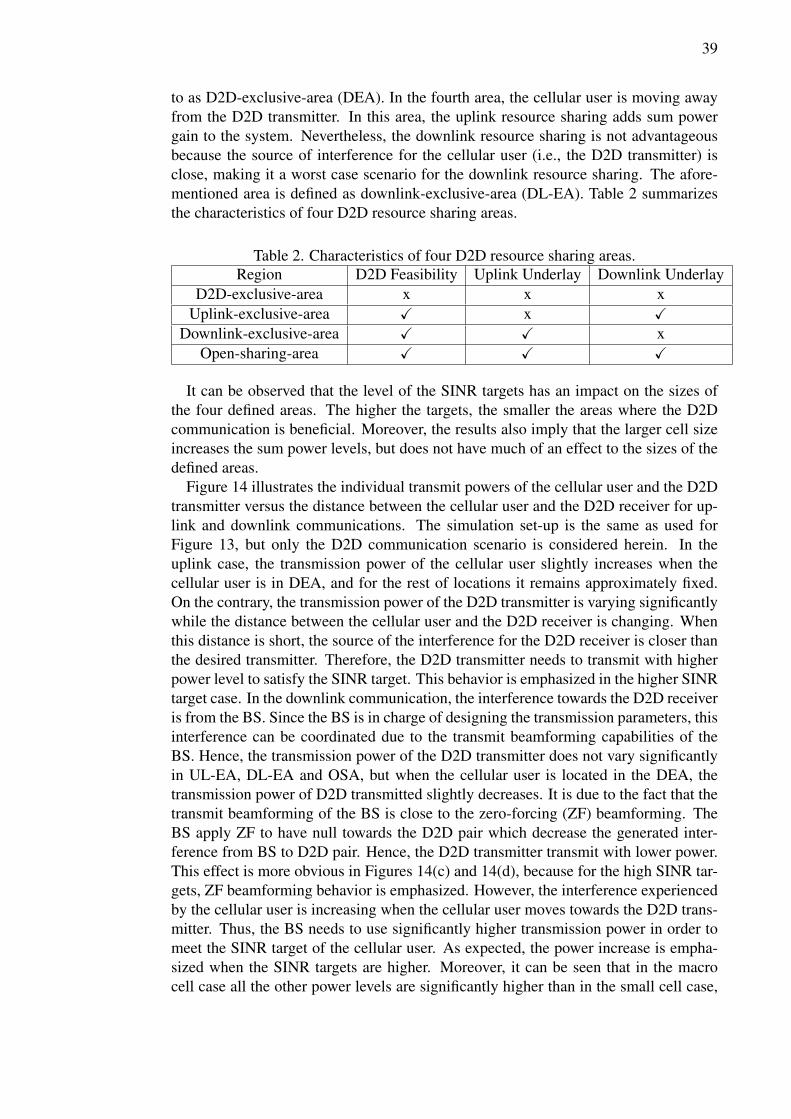
Figure 14 illustrates the individual transmit powers of the cellular user and the D2Dtransmitter versus the distance between the cellular user and the D2D receiver for up-link and downlink communications. The simulation set-up is the same as used forFigure 13, but only the D2D communication scenario is considered herein. In theuplink case, the transmission power of the cellular user slightly increases when thecellular user is in DEA, and for the rest of locations it remains approximately fixed.On the contrary, the transmission power of the D2D transmitter is varying significantlywhile the distance between the cellular user and the D2D receiver is changing. Whenthis distance is short, the source of the interference for the D2D receiver is closer thanthe desired transmitter. Therefore, the D2D transmitter needs to transmit with higherpower level to satisfy the SINR target. This behavior is emphasized in the higher SINRtarget case. In the downlink communication, the interference towards the D2D receiveris from the BS. Since the BS is in charge of designing the transmission parameters, thisinterference can be coordinated due to the transmit beamforming capabilities of theBS. Hence, the transmission power of the D2D transmitter does not vary significantlyin UL-EA, DL-EA and OSA, but when the cellular user is located in the DEA, thetransmission power of D2D transmitted slightly decreases. It is due to the fact that thetransmit beamforming of the BS is close to the zero-forcing (ZF) beamforming. TheBS apply ZF to have null towards the D2D pair which decrease the generated inter-ference from BS to D2D pair. Hence, the D2D transmitter transmit with lower power.This effect is more obvious in Figures 14(c) and 14(d), because for the high SINR tar-gets, ZF beamforming behavior is emphasized. However, the interference experiencedby the cellular user is increasing when the cellular user moves towards the D2D trans-mitter. Thus, the BS needs to use significantly higher transmission power in order tomeet the SINR target of the cellular user. As expected, the power increase is empha-sized when the SINR targets are higher. Moreover, it can be seen that in the macrocell case all the other power levels are significantly higher than in the small cell case,
40
except the power of the D2D transmitter. This can be explained by the interferencecoordination performed by the BS via transmit beamforming. Moreover, the pathlossbetween the interfering BS and the D2D receiver is also increased with the larger cellsize.
−50 −40 −30 −20 −10 0 10 20 30 40 50
−130
−120
−110
−100
−90
−80
−70
−60
Sum
Pow
er
[dB
m]
cu−drx Distance, Lcu,drx
[m]
γ = 0dB, R = 50m, Ldtx,drx
= 10m
p
dtx, D2D uplink
pcu
, D2D uplink
p∼
dtx, D2D downlink
p∼
cu, D2D downlink
(a)
−50 −40 −30 −20 −10 0 10 20 30 40 50
−130
−120
−110
−100
−90
−80
−70
−60
−50
−40
−30
Sum
Pow
er
[dB
m]
cu−drx Distance, Lcu,drx
[m]
γ = 0dB, R = 400m, Ldtx,drx
= 10m
p
dtx, D2D uplink
pcu
, D2D uplink
p∼
dtx, D2D downlink
p∼
cu, D2D downlink
(b)
−50 −40 −30 −20 −10 0 10 20 30 40 50−130
−120
−110
−100
−90
−80
−70
−60
−50
−40
Sum
Pow
er
[dB
m]
cu−drx Distance, Lcu,drx
[m]
γ = 10dB, R = 400m, Ldtx,drx
= 10m
p
dtx, D2D uplink
pcu
, D2D uplink
p∼
dtx, D2D downlink
p∼
cu, D2D downlink
(c)
−50 −40 −30 −20 −10 0 10 20 30 40 50−140
−120
−100
−80
−60
−40
−20
0
Sum
Pow
er
[dB
m]
cu−drx Distance, Lcu,drx
[m]
γ = 10dB, R = 400m, Ldtx,drx
= 10m
p
dtx, D2D uplink
pcu
, D2D uplink
p∼
dtx, D2D downlink
p∼
cu, D2D downlink
(d)
Figure 14. Individual transmitter powers versus distance between cellular user andD2D receiver for uplink and downlink communications.
5.4. Impact of SINR Targets
This section provides a study on the effect of the different target SINRs on the achiev-able power gain. In this simulation scenario, the D2D distance is fixed to 10m and the
41
distance between the cellular user and D2D receiver is fixed to 27m for both cases ofsmall and macro cells.
0 2 4 6 8 10 12 14 16 18 20−115
−110
−105
−100
−95
−90
−85
−80
Sum
Pow
er [d
Bm
]
SINR target, g [dB]
R = 50m, Lcu,drx
= 27m, Ldtx,drx
= 10m
D2D downlinkD2D uplinkCellular uplinkCellular downlink
(a)
0 2 4 6 8 10 12 14 16 18 20−80
−75
−70
−65
−60
−55
−50
−45
Sum
Pow
er [d
Bm
]
SINR target, g [dB]
R = 400m, Lcu,drx
= 27m, Ldtx,drx
= 10m
D2D downlinkD2D uplinkCellular uplinkCellular downlink
(b)
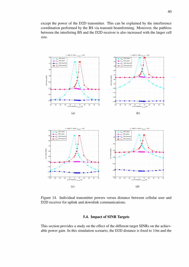
Figure 15. Sum power versus SINR target for uplink and downlink communications.
0 2 4 6 8 10 12 14 16 18 20−130
−125
−120
−115
−110
−105
−100
−95
−90
−85
−80
Sum
Pow
er
[dB
m]
SINR target, γ [dB]
R = 50m, Lcu,drx
= 27m, Ldtx,drx
= 10m
p
dtx, D2D uplink
pcu
, D2D uplink
p∼
dtx, D2D downlink
p∼
cu, D2D downlink
(a)
0 2 4 6 8 10 12 14 16 18 20−130
−120
−110
−100
−90
−80
−70
−60
−50
−40
Sum
Pow
er
[dB
m]
SINR target, γ [dB]
R = 400m, Lcu,drx
= 27m, Ldtx,drx
= 10m
p
dtx, D2D uplink
pcu
, D2D uplink
p∼
dtx, D2D downlink
p∼
cu, D2D downlink
(b)
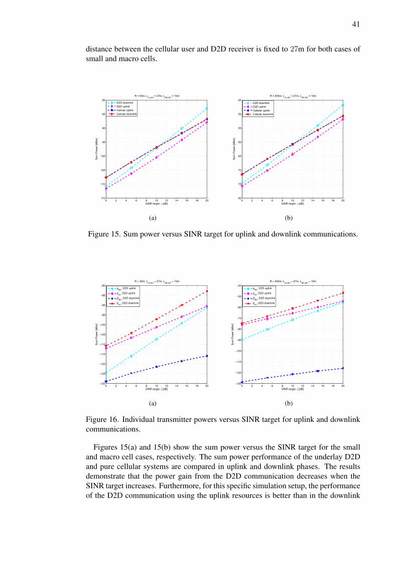
Figure 16. Individual transmitter powers versus SINR target for uplink and downlinkcommunications.
Figures 15(a) and 15(b) show the sum power versus the SINR target for the smalland macro cell cases, respectively. The sum power performance of the underlay D2Dand pure cellular systems are compared in uplink and downlink phases. The resultsdemonstrate that the power gain from the D2D communication decreases when theSINR target increases. Furthermore, for this specific simulation setup, the performanceof the D2D communication using the uplink resources is better than in the downlink
42
case. It can be seen that when the SINR targets increase, the sum power gain decreasesfor both downlink and uplink, but the degradation of the downlink power gain is fasterthan the uplink power gain. Hence, for the SINR targets higher than 10dB the D2Ddownlink degrade the performance of cellular network.
In Figures 16(a) and 16(b), the individual per-transmitter powers are plotted againstthe SINR target for the same small and macro cell scenarios as previously. In theseFigures, only the underlaying D2D communication scenario is considered. It can beseen that the transmit powers of the D2D communication are much lower in compari-son to the powers in the cellular communication. Furthermore, the used power of theD2D transmitter is significantly lower in the downlink than in the uplink phase. Thisis again due to the transmit beamforming performed at the BS. This performance be-havior is further emphasized when the cell size grows. Consequently, in the macro cellcase, all the other power levels are significantly increased, except the D2D transmitpower in the downlink phase.
43
6. DISCUSSION
The goal of this thesis is to study network assisted D2D communications underlayingcellular networks while proposing the algorithms to underlay uplink and downlinkresources. To achieve this purpose, coordinated beamforming approaches in cellularnetworks are studied. Both centralized and decentralized approaches of coordinatedbeamforming in cellular networks has been considered. It leads to facilitating D2Dcommunication underlaying cellular networks to increase the energy efficiency of thecellular networks.
Based on the algorithms studied in Chapter 3, novel algorithms are proposed to en-hance energy efficiency of D2D communications underlaying cellular networks. Thealgorithms minimize the total transmission power while guaranteeing the user specificrate constraints. The algorithm proposed for D2D communications underlaying uplinkis based on the joint power control and receive beamforming algorithm using simi-lar ideas as presented in [59–61]. For D2D communications underlaying downlink,the proposed algorithm is based on the SOCP. The performance of the algorithms arebenchmarked with conventional cellular networks. The results show that algorithmsadd significant power gain to the cellular networks. This gain is achieved because theproposed algorithms manage to successfully reduce the interference using power con-trol and beamforming techniques. In particular, the proposed algorithms harness theinterference caused by D2D communications so that successful cellular communica-tions is guaranteed. Additionally, a decentralized approach is designed based on theprinciples introduced in [54]. This algorithm uses standard dual decomposition ap-proach to solve the optimization problem individually at each transmitter. Therefore,the original optimization problem can be solved at each BS using local CSI. The de-centralized algorithm aims to reduce the amount of control information exchange incomparison with the centralized approach.
Majority of prior works on power allocation for D2D communications underlayingcellular networks did not consider the implementation requirements and challenges oftheir proposed algorithms. However, Chapter 4 discussed the implementation chal-lenges of the proposed centralized and decentralized algorithms. The main challengesfor implementing the proposed sum power minimization algorithms are channel mea-surements, CSI feedback, and power updates via over-the-air signaling. Although theproposed centralized algorithms require global CSI knowledge at the BS side, sendingthe channel states of the users in scalar forms greatly reduces the bandwidth consumedfor feedback reporting. Moreover, the decentralized algorithm allows the BS to per-form beamforming with limited information exchange among interfering transmitter.It is worth mentioning that in the considered simple system model, the use of the cen-tralized approach might be a better choice since only the scalar channels need to besignaled to the BS by the users via over-the-air signaling. However, the role of thedecentralized approach is emphasized for larger multi-cell systems with multiantennausers.
The numerical analysis of the algorithm is provided in Chapter 5. There are threeparameters which play the main role in the considered simulation scenarios, i.e., thedistance between users, the SINR targets, and the cell size. The numerical simulationsshowed that: (i) increasing the distance between the D2D pairs reduce the systemperformance. This happens because the D2D transmission power is higher for larger
44
distances which in turn results in higher interference; (ii) larger distance between theD2D pair and cellular user leads to better system performance because the interferencebetween the D2D and cellular transmission is inversely proportional with distance;(iii) for the higher SINR targets, the D2D performance gain decreases more rapidly ascompared with the lower SINR targets. This is due to the increased interference sincethe transmission powers need to be higher; (iv) the total sum power increases withcell size due to the pathloss effect. Considering the importance of these parameterson the system performance, it is crucial to take them into account in the design ofD2D systems. Interestingly, studying the impact of these parameters on the systemperformance showed that the cell area can be divided into four different areas. Eacharea has certain characteristics in terms of the feasibility of D2D communication andthe type of resources used for D2D communication. The characteristic of these areasare shown in Table 2. It should be noted that the aforementioned parameters (e.g.,user distance, target SINR, etc.) affect the coverage of these areas. One of the mainoutcome of the numerical analysis is that implementation of smart mode selectioncan increase the performance of algorithm. According to the position of the cellularuser, the algorithm should decide about the optimal transmitter and the best resourceto be shared. Therefore, the algorithm combines the second and third areas. Thus,adding smart mode selection to the current algorithms is an interesting future researchdirection.
The aforementioned results are obtained from a simple scenario consisting of a BS,a cellular user, and a D2D pair. However, the results can be better justified in a morerealistic multi-cell scenario with higher number of D2D and cellular users, and moresophisticated channel model. Nevertheless, these additions make the sum power min-imization problem more complicated. Another potential future direction is to inves-tigate the behavior of the system when the users are not only located on the edge.Investigating the performance of the proposed decentralized algorithm in a multi-cellscenario is also an interesting future research direction. For the sake of tractability, thesum power minimization design was considered so that a clear understanding of prosand cons of the D2D underlaying cellular network can be provided. Furthermore, con-sidering other optimization criteria such as spectral efficiency or WSR maximizationsare good candidates for further research. These new optimization criteria are moreinteresting from the practical point of view. Channel estimation and CSI availabilityat the BS (especially from D2D transmitter) is also an important issue. For instance,the BS may not be able to sense the pilot signals from D2D transmitters due to theirlow transmission power. A potential solution could be defining D2D specific signalingin which the transmitter sends pilot signals with higher power. Thus, design of D2Dspecific signaling can be another line for future research.
45
7. SUMMARY
The aim of this thesis was to study the energy efficiency of D2D communicationsunderlaying cellular networks. In particular, algorithms for sum power minimizationfor both uplink and downlink resource sharing between D2D pair and cellular user areproposed. Moreover, the proposed algorithms are benchmarked against conventionalcellular systems.
In Chapter 2, D2D communications in cellular networks is introduced and the re-lated literature on the topic is reviewed. Chapter 3 reviews network-coordinated beam-forming techniques in cellular networks. In Chapter 4, the problem of the interferencemanagement in underlay D2D scenarios is elaborated. In particular, the sum power op-timization problems for the downlink and uplink resource sharing are formulated. Theobjective of the optimization problems is to minimize the sum power consumption ofthe network constrained with per user rate target. In order to solve the optimizationproblems, novel algorithms are proposed which minimize the sum power consumptionof the network in both uplink and downlink directions. The proposed algorithm forsolving the optimization problem in uplink is based on joint uplink power control andreceive beamforming algorithm. In the downlink, the power minimization problemis casted as an SOCP, which can be then solved optimally via centralized process-ing. In addition to the centralized solution, a decentralized dual decomposition-basedalgorithm is proposed for the downlink case. The implementation challenges of theproposed power control and beamforming algorithms for the D2D communicationsare also discussed.
The proposed algorithms are benchmarked against the conventional cellular networkvia Matlab-based simulations. The single-cell simulation model consists of a cellularuser and a single D2D pair, which share the same cellular spectrum. The simulationresults showed that the locations of the cellular user and D2D pair play importantroles for the resource sharing between them. Based on these results, four different re-source sharing areas, namely, D2D-exclusive-area , uplink-exclusive-area, downlink-exclusive-area, and open-sharing-area, for D2D communication are defined. The re-sults showed that the proposed algorithms can reduce the sum power consumption ofthe network by 5dB at best.
46
8. REFERENCES
[1] Holma H. & Toskala A. (2000) WCDMA for UMTS, vol. 4. Citeseer.
[2] Astely D., Dahlman E., Furuskar A., Jading Y., Lindstrom M. & Parkvall S.(2009) LTE: the evolution of mobile broadband. IEEE Communications Mag-azine 47, pp. 44–51.
[3] Doppler K., Yu C.H., Ribeiro C.B. & Janis P. (2010) Mode selection for device-to-device communication underlaying an LTE-advanced network. In: IEEE Wire-less Communications and Networking Conference (WCNC), 2010, pp. 1–6.
[4] Wang B., Chen L., Chen X., Zhang X. & Yang D. (2011) Resource allocationoptimization for device-to-device communication underlaying cellular networks.In: IEEE 73rd Vehicular Technology Conference (VTC Spring), 2011, pp. 1–6.
[5] Yu C.H., Doppler K., Ribeiro C. & Tirkkonen O. (2009) Performance impact offading interference to device-to-device communication underlaying cellular net-works. In: IEEE 20th International Symposium on Personal, Indoor and MobileRadio Communications, 2009, pp. 858–862.
[6] Doppler K., Rinne M., Wijting C., Ribeiro C. & Hugl K. (2009) Device-to-devicecommunication as an underlay to LTE-advanced networks. IEEE Communica-tions Magazine 47, pp. 42–49.
[7] Fodor G. & Reider N. (2011) A distributed power control scheme for cellularnetwork assisted D2D communications. In: IEEE Global TelecommunicationsConference (GLOBECOM 2011), pp. 1–6.
[8] Belleschi M., Fodor G. & Abrardo A. (2011) Performance analysis of a dis-tributed resource allocation scheme for D2D communications. In: IEEE GLOBE-COM Workshops (GC Wkshps), 2011, pp. 358–362.
[9] Min H., Seo W., Lee J., Park S. & Hong D. (2011) Reliability improvement usingreceive mode selection in the device-to-device uplink period underlaying cellularnetworks. IEEE Transactions on Wireless Communications 10, pp. 413–418.
[10] Xu Y., Yin R., Han T. & Yu G. (2012) Interference-aware channel allocationfor device-to-device communication underlaying cellular networks. In: 1st IEEEInternational Conference on Communications in China (ICCC), 2012, pp. 422–427.
[11] Yu C.H., Tirkkonen O., Doppler K. & Ribeiro C. (2009) Power optimization ofdevice-to-device communication underlaying cellular communication. In: IEEEInternational Conference on Communications, 2009. ICC ’09., pp. 1–5.
[12] Yu C.H., Tirkkonen O., Doppler K. & Ribeiro C. (2009) On the performance ofdevice-to-device underlay communication with simple power control. In: IEEE69th on Vehicular Technology Conference, 2009., pp. 1–5.
47
[13] Yu C.H., Doppler K., Ribeiro C.B. & Tirkkonen O. (2011) Resource sharingoptimization for device-to-device communication underlaying cellular networks.IEEE Transactions on Wireless Communications 10, pp. 2752–2763.
[14] Xiao X., Tao X. & Lu J. (2011) A QoS-aware power optimization scheme inOFDMA systems with integrated device-to-device (D2D) communications. In:IEEE Vehicular Technology Conference (VTC Fall), 2011, pp. 1–5.
[15] Jänis P., Yu C.H., Doppler K., Ribeiro C.B., Wijting C., Hugl K., TirkkonenO. & Koivunen V. (2009) Device-to-device communication underlaying cellularcommunications systems. IJCNS 2, pp. 169–178.
[16] Janis P., Koivunen V., Ribeiro C., Korhonen J., Doppler K. & Hugl K. (2009)Interference-aware resource allocation for device-to-device radio underlayingcellular networks. In: IEEE 69th Vehicular Technology Conference, 2009. VTCSpring 2009., pp. 1–5.
[17] Fodor G., Dahlman E., Mildh G., Parkvall S., Reider N., Miklos G. & TuranyiZ. (2012) Design aspects of network assisted device-to-device communications.IEEE Communications Magazine 50, pp. 170–177.
[18] Corson M.S., Laroia R., Li J., Park V., Richardson T. & Tsirtsis G. (2010) Towardproximity-aware internetworking. IEEE Wireless Communications 17, pp. 26–33.
[19] Peng T., Lu Q., Wang H., Xu S. & Wang W. (2009) Interference avoidance mech-anisms in the hybrid cellular and device-to-device systems. In: IEEE 20th In-ternational Symposium on Personal, Indoor and Mobile Radio Communications,2009, pp. 617–621.
[20] Haykin S. (2005) Cognitive radio: brain-empowered wireless communications.IEEE Journal on Selected Areas in Communications 23, pp. 201–220.
[21] Mitola J. & Jr. G.Q.M. (1999) Cognitive radio: making software radios morepersonal. IEEE Personal Communications 6, pp. 13–18.
[22] Phunchongharn P., Hossain E. & Kim D. (2013) Resource allocation for device-to-device communications underlaying LTE-advanced networks. Wireless Com-munications, IEEE 20, pp. 91–100.
[23] Asadi A. & Mancuso V. (2013) WiFi direct and LTE D2D in action. WirelessDays 2013, Valencia, Spain .
[24] Golrezaei N., Dimakis A.G. & Molisch A.F. (2012) Device-to-device collabora-tion through distributed storage. In: IEEE Global Communications Conference(GLOBECOM), 2012, pp. 2397–2402.
[25] Wu J., Chen H.Z.B., Liu Y. & Cai L. (2011) User clustering and energy efficientcooperation in cellular networks. In: Conference Record of the Forty Fifth Asilo-mar Conference on Signals, Systems and Computers (ASILOMAR), 2011, pp.1650–1654.
48
[26] Asadi A., Wang Q. & Mancuso V. (2013) A survey on device-to-device commu-nication in cellular networks. http://arxiv.org/abs/1310.0720 .
[27] Chien C.P., Chen Y.C. & Hsieh H.Y. (2012) Exploiting spatial reuse gain throughjoint mode selection and resource allocation for underlay device-to-device com-munications. In: 15th International Symposium on Wireless Personal MultimediaCommunications (WPMC), 2012, pp. 80–84.
[28] Messenger S. (1991), Wireless local area network. US Patent 5,046,066.
[29] Group I..W. (2003) Standard for part 15.4: Wireless medium access control(MAC) and physical layer (PHY) specifications for low rate wireless personalarea networks (LR-WPANs). ANSI/IEEE 802.15 4.
[30] Bluetooth S. (2001) Bluetooth specification version 1.1. Available HTTP:http://www.bluetooth.com .
[31] Jung M., Hwang K. & Choi S. (2012) Joint mode selection and power allocationscheme for power-efficient device-to-device (D2D) communication. In: IEEE75th Vehicular Technology Conference (VTC Spring), 2012, pp. 1–5.
[32] Xiang S., Quan Q., Peng T. & Wang W. (2012) Performance analysis of cooper-ative mode selection in hybrid D2D and IMT-advanced network. In: 7th Interna-tional ICST Conference on Communications and Networking in China (CHINA-COM), 2012, pp. 717–721.
[33] Liu Z., Peng T., Xiang S. & Wang W. (2012) Mode selection for device-to-device(D2D) communication under LTE-advanced networks. In: IEEE InternationalConference on Communications (ICC), 2012, pp. 5563–5567.
[34] Perkins C.E. (2001) Ad hoc networking, vol. 1. Addison-wesley Reading.
[35] Zhou B., Hu H., Huang S. & Chen H. (2013) Intra-cluster device-to-device relayalgorithm with optimal resource utilization .
[36] Wen S., Zhu X., Lin Z., Zhang X. & Yang D. (2012) Optimization of interferencecoordination schemes in device-to-device(D2D) communication. In: 7th Interna-tional ICST Conference on Communications and Networking in China (CHINA-COM), 2012, pp. 542–547.
[37] da S Rego M.G., Maciel T.F., de H M Barros H., Cavalcanti F.R.P. & FodorG. (2012) Performance analysis of power control for device-to-device commu-nication in cellular MIMO systems. In: International Symposium on WirelessCommunication Systems (ISWCS), 2012, pp. 336–340.
[38] Hakola S., Chen T., Lehtomaki J. & Koskela T. (2010) Device-to-device (D2D)communication in cellular network - performance analysis of optimum and prac-tical communication mode selection. In: IEEE Wireless Communications andNetworking Conference (WCNC), 2010, pp. 1–6.
49
[39] Janis P., Koivunen V., Ribeiro C.B., Doppler K. & Hugl K. (2009) Interference-avoiding MIMO schemes for device-to-device radio underlaying cellular net-works. In: IEEE 20th International Symposium on Personal, Indoor and MobileRadio Communications, 2009, pp. 2385–2389.
[40] ALLIANCE W. (2010) Wi-Fi peer-to-peer (P2P) specification v1. 1. WI-FI AL-LIANCE SPECIFICATION 1, pp. 1–159.
[41] Lei L., Zhong Z., Lin C. & Shen X. (2012) Operator controlled device-to-devicecommunications in LTE-advanced networks. IEEE Wireless Communications 19,pp. 96–104.
[42] Zhou B., Hu H., Huang S.Q. & Chen H.H. (2013) Intracluster device-to-devicerelay algorithm with optimal resource utilization. IEEE Transactions on VehicularTechnology 62, pp. 2315–2326.
[43] Du J., Zhu W., Xu J., Li Z. & Wang H. (2012) A compressed HARQ feedbackfor device-to-device multicast communications. In: IEEE Vehicular TechnologyConference (VTC Fall), 2012, pp. 1–5.
[44] Golrezaei N., Molisch A.F. & Dimakis A.G. (2012) Base-station assisted device-to-device communications for high-throughput wireless video networks. In:IEEE International Conference on Communications (ICC), 2012, pp. 7077–7081.
[45] Li J.C.F., Lei M. & Gao F. (2012) Device-to-device (D2D) communication inMU-MIMO cellular networks. In: IEEE Global Communications Conference(GLOBECOM), 2012, pp. 3583–3587.
[46] Pratas N.K. & Popovski P. (2013) Low-rate machine-type communication viawireless device-to-device (D2D) links. arXiv preprint arXiv:1305.6783 .
[47] Kaufman B. & Aazhang B. (2008) Cellular networks with an overlaid device todevice network. In: 42nd Asilomar Conference on Signals, Systems and Com-puters, 2008, pp. 1537–1541.
[48] Xu S., Wang H., Chen T., Huang Q. & Peng T. (2010) Effective interference can-cellation scheme for device-to-device communication underlaying cellular net-works. In: IEEE 72nd Vehicular Technology Conference Fall (VTC 2010-Fall),2010, pp. 1–5.
[49] Chen X., Chen L., Zeng M., Zhang X. & Yang D. (2012) Downlink resource al-location for device-to-device communication underlaying cellular networks. In:IEEE 23rd International Symposium on Personal Indoor and Mobile Radio Com-munications (PIMRC), 2012, pp. 232–237.
[50] Min H., Lee J., Park S. & Hong D. (2011) Capacity enhancement using an inter-ference limited area for device-to-device uplink underlaying cellular networks.IEEE Transactions on Wireless Communications 10, pp. 3995–4000.
50
[51] Zulhasnine M., Huang C. & Srinivasan A. (2010) Efficient resource allocation fordevice-to-device communication underlaying LTE network. In: IEEE 6th Inter-national Conference on Wireless and Mobile Computing, Networking and Com-munications (WiMob), 2010, pp. 368–375.
[52] Sesia S., Toufik I. & Baker M. (2009) LTE: the UMTS long term evolution. WileyOnline Library.
[53] Gesbert D., Hanly S., Huang H., Shitz S.S., Simeone O. & Yu W. (2010) Multi-cell MIMO cooperative networks: A new look at interference. IEEE Journal onSelected Areas in Communications 28, pp. 1380–1408.
[54] Tolli A., Pennanen H. & Komulainen P. (2011) Decentralized minimum powermulti-cell beamforming with limited backhaul signaling. IEEE Transactions onWireless Communications 10, pp. 570–580.
[55] Venturino L., Prasad N. & Wang X. (2008) Coordinated linear beamforming indownlink multi-cell wireless networks. In: 42nd Asilomar Conference on Sig-nals, Systems and Computers, 2008, pp. 356–360.
[56] Komulainen P., Tolli A. & Juntti M. (2012) Low overhead effective CSI sig-naling for beam coordination in TDD multi-cell MIMO systems. In: IEEE 23rdInternational Symposium on Personal Indoor and Mobile Radio Communications(PIMRC), 2012, pp. 1656–1661.
[57] Schubert M. & Boche H. (2004) Solution of the multiuser downlink beamform-ing problem with individual SINR constraints. IEEE Transactions on VehicularTechnology 53, pp. 18–28.
[58] Pennanen H., Tolli A. & Latva-aho M. (2011) Decentralized coordinated down-link beamforming via primal decomposition. IEEE Signal Processing Letters 18,pp. 647–650.
[59] Rashid-Farrokhi F., Tassiulas L. & Liu K.J.R. (1998) Joint optimal power controland beamforming in wireless networks using antenna arrays. IEEE Transactionson Communications 46, pp. 1313–1324.
[60] Ulukus S. & Yates R. (1998) Adaptive power control and MMSE interferencesuppression. Wireless Networks 4, pp. 489–496. URL: http://dx.doi.org/10.1023/A%3A1019101700730.
[61] Chiang M., Hande P., Lan T. & Tan C.W. (2008) Power control in wireless cellularnetworks. Found. Trends Netw. 2, pp. 381–533. URL: http://dx.doi.org/10.1561/1300000009.
[62] Rashid-Farrokhi F., Liu K.J.R. & Tassiulas L. (1998) Transmit beamforming andpower control for cellular wireless systems. IEEE Journal on Selected Areas inCommunications 16, pp. 1437–1450.
[63] Dahrouj H. & Yu W. (2010) Coordinated beamforming for the multicell multi-antenna wireless system. IEEE Transactions on Wireless Communications 9, pp.1748–1759.

51
[64] Wiesel A., Eldar Y.C. & Shamai S. (2006) Linear precoding via conic optimiza-tion for fixed MIMO receivers. IEEE Transactions on Signal Processing 54, pp.161–176.
[65] Shen C., Chang T.H., Wang K.Y., Qiu Z. & Chi C.Y. (2012) Distributed robustmulticell coordinated beamforming with imperfect CSI: An ADMM approach.IEEE Transactions onSignal Processing 60, pp. 2988–3003.
[66] Yu W. & Lan T. (2007), Transmitter optimization for the multi-antenna downlinkwith per-antenna power constraints.
[67] Grant M. & Boyd S. (2013), CVX: Matlab software for disciplined convex pro-gramming, version 2.0 beta. http://cvxr.com/cvx.
[68] Grant M. & Boyd S. (2008) Graph implementations for nonsmooth convexprograms. In: V. Blondel, S. Boyd & H. Kimura (eds.) Recent Advances inLearning and Control, Lecture Notes in Control and Information Sciences,Springer-Verlag Limited, pp. 95–110. http://stanford.edu/~boyd/graph_dcp.html.