Embed Size (px)
Citation preview

DEGREE PROGRAMME IN WIRELESS COMMUNICATIONS ENGINEERING
MASTER’S THESIS
INTEGRATION OF LORA WIDE AREA
NETWORK WITH THE 5G TEST NETWORK
Author Rumana Yasmin
Supervisor Prof. Ari Pouttu
Second Examiner Dr. Heikki Karvonen
Technical Advisor M.Sc. Juha Petäjäjärvi,
M.Sc. Konstantin Mikhaylov
April 2017

Yasmin R. (2017) Integration of LoRa Wide Area Network with the 5G Test
Network. University of Oulu, Degree Programme in Wireless Communications
Engineering. Master’s Thesis, 63 p.
ABSTRACT
The global communication network is going through major transformation from
conventional to more versatile and diversified network approaches. With the
advent of virtualization and cloud technology, information technology (IT) is
merging with telecommunications to alter the conventional approaches of
traditional proprietary networking techniques. From radio to network and
applications, the existing infrastructure lacks several features that we wished to
be part of 5th Generation Mobile Networks (5G). Having a support for large
number of applications, Internet of Things (IoT) will bring a major evolution by
creating a comfortable, flexible and an automated environment for end users. A
network having the capability to support radio protocols on top of basic
networking protocols, when blended with a platform which can generate IoT use
cases, can make the expectations of 5G a reality.
Low Power Wide Area Network (LPWAN) technologies can be utilized with
other emerging and suitable technologies for IoT applications. To implement a
network where all the technologies can be deployed virtually to serve their
applications within a single cloud, Network Functions Virtualization (NFV) and
Software Defined Network (SDN) is introduced to implement such a networking
possibility for upcoming technologies. The 5G Test Network (5GTN), a testbed
for implementing and testing 5G features in real time, is deployed in virtual
platform which allows to add other technologies for IoT applications. To
implement a network with an IoT enabler technology, LoRa Wide Area Network
(LoRaWAN) technology can be integrated to test the feasibility and capability of
IoT implications. LoRaWAN being an IoT enabler technology is chosen out of
several possibilities to be integrated with the 5GTN. Using MultiConnect Conduit
as a gateway, the integration is realized by establishing point to point protocol
(PPP) connection with eNodeB. Once the connection is established, LoRa packets
are forwarded to the ThingWorx IoT cloud and responses can be received by the
end-devices from that IoT cloud by using Message Queuing Telemetry Transport
(MQTT) protocol. Wireshark, an open source packet analyser, is then used to
ensure successful transmission of packets to the ThingWorx using the 5GTN
default packet routes.
Key words: LPWAN, LoRaWAN, 5GTN, NFV, SDN, OpenEPC, IoT,
MultiConnect Conduit, Node-red, MQTT, ThingWorx.

TABLE OF CONTENTS
ABSTRACT
TABLE OF CONTENTS
FOREWORD
LIST OF ABBREVIATIONS AND SYMBOLS
1. INTRODUCTION ............................................................................................ 10
1.1. Demand for LPWAN Integration with the 5GTN ................................... 11
1.2. Thesis Objectives ..................................................................................... 12
1.3. Research Approach .................................................................................. 13
1.4. Thesis Structure ....................................................................................... 13
2. LOW POWER WIDE AREA NETWORK ...................................................... 14
2.1. LoRa Technology .................................................................................... 15
2.2. Physical Layer ......................................................................................... 16
2.3. Media Access Control Layer ................................................................... 17
2.4. Network Architecture .............................................................................. 18
2.5. Message Format ....................................................................................... 19
2.5.1. MAC Frame Formats ................................................................... 20
2.5.2. MAC Commands ......................................................................... 21
2.6. Device Attachment Procedures ............................................................... 21
2.7. Network Security ..................................................................................... 22
3. 5G TEST NETWORK ...................................................................................... 23
3.1. Architectural Overview of the 5G Test Network .................................... 23
3.2. Network Function Virtualization ............................................................. 25
3.3. Software Defined Network ...................................................................... 26
3.4. Evolved Packet Core ............................................................................... 26
3.5. OpenEPC ................................................................................................. 28
3.5.1. OpenEPC as a Core Network ...................................................... 28
3.5.2. OpenEPC Components ................................................................ 29
3.5.3. LTE access network signalling in a nutshell ............................... 31
3.5.4. Signalling route over Non-3GPP ................................................. 33
4. LORAWAN INTEGRATION WITH THE 5GTN ........................................... 35
4.1. Integration at a Glance ............................................................................. 35
4.2. Levels of Integration ................................................................................ 36
4.2.1. LoRaWAN as an Access Network .............................................. 37
4.2.2. Connecting LoRaWAN to 5GvLAN ........................................... 38
4.2.3. LoRaWAN being a part of LTE-UE ............................................ 38
4.2.4. LoRaWAN being part of eNodeB ............................................... 39
4.2.5. LoRa Network Server on OpenStack .......................................... 40
5. IMPLEMENTATION ....................................................................................... 41
5.1. Integration Scenario ................................................................................. 41
5.2. MultiConnect Conduit ............................................................................. 42

5.2.1. Provisioning to Access Terminal Interface via Ethernet ............. 43
5.2.2. Receiving packets on the Node-red ............................................. 44
5.2.3. Point-to-Point Protocol ................................................................ 44
5.2.4. WAN Connection Establishment ................................................. 45
5.2.5. Message Queue Telemetry Transport protocol............................ 47
5.2.6. Forwarding Packets to the ThingWorx Cloud ............................. 48
5.3. Monitoring LoRa Packet ......................................................................... 53
5.3.1. Wireshark Traces for MQTT packets .......................................... 53
6. DISCUSSION ................................................................................................... 55
7. SUMMARY ...................................................................................................... 57
FOREWORD
The thesis work is completed at Centre for Wireless Communications research unit at
University of Oulu as a partial fulfilment of master degree requirement in Wireless
Communications Engineering. The accomplishment of the thesis work set pointers to
future research around IoT applications. The work gave me an insight to the practical
implications of the theoretical knowledge I have been familiar with. The practical
guidance from experts having profound industrial experience has provided me with
the knowledge I was lacking. The completion of my work is only possible due to the
guidance of esteemed researchers working in this diverse research unit. My words of
gratitude to the technical advisor on my thesis, M.Sc. Juha Petäjäjärvi. Your guidance
at each stage made the timely accomplishment of the work possible. M.Sc. Konstantin
Mikhaylov, thanks for being part of my journey, your suggestions gave me directions
to get the work done. I am very much thankful to the 5GTN team especially
Muhammad Arif, Jaakko Leinonen and Jari Marjakangas as there is no parallel to the
cooperation and support provided by them. You guys made yourself available all the
time and made the availability of the required resources possible. My supervisor on
the thesis, Prof. Ari Pouttu, thanks for your support and guidance. Without your
directions, the completion of the work was not possible.
Whoever reads my thesis work many years from now, I can understand the hardship
and struggle you are going through. Please do not lose hope as there is always a bright
light at the end of a tunnel. I also faced hard times, struggling to figure out possible
solutions and I managed to solve my problems at the end. So, just stay focused and
keep doing the good work, nothing is impossible. You will find solutions to your
problems as I did.
Oulu, April 13, 2017
Rumana Yasmin

LIST OF ABBREVIATIONS AND SYMBOLS
3GPP 3rd Generation Partnership Project
4G 4th Generation Mobile Networks
5G 5Th Generation Mobile Networks
5GTN 5G Test Network
5GvLAN 5G virtual Local Area Network
AAA Authentication, Authorization and Accounting
ABP Activation by Personalization
ADR Adaptive Data Rate
ANDSF Access Network Discovery and Selection Function
API Application Programmable Interface
APN Access Point Name
AppEUI Application Identifier
AppSKey Application Session Key
BS Base Station
CAPEX Capital Expenditure
CND Core Network Dynamic
CoAP Constrained Application Protocol
CRC Cyclic Redundancy Check
CSS Chirp Spread Spectrum
DC Data Centre
DevEUI End-Device Identifier
DHCP Dynamic Host Configuration Protocol
DL Downlink
DNS Domain Name System
EMS Element Management System
eNodeB Evolved Node B
EPC Evolved Packet Core
ePDG Evolved Packet Data Gateway
EPS Evolved Packet System
ETSI European Telecommunications Standards Institute
E-UTRAN Evolved Universal Terrestrial Radio Access Network
FCC Federal Communications Commission
FCnt Frame Counter
FCntrl Frame Controller
FDD Frequency Division Duplex
FHDR Frame Header
FOpts Frame Options
FRMPayload Frame Payload
GPRS General Packet Radio Service
GPS Global Positioning System
GTP GPRS Tunnelling Protocol

GTP-C GTP- Control plane
GTP-U GTP- User plane
HSS Home Subscribe Server
ICT Information and Communications Technology
I-CSCF Interrogating-Call Session Control Function
IMS IP Multimedia Subsystem
IMSI International Mobile Subscriber Identity
IoT Internet of Things
IP Internet Protocol
IPSec Internet Protocol Security
ISAKMP Internet Security Association and Key Management Protocol
ISM Industrial, Scientific, and Medical
IT Information Technology
JSON JavaScript Object Notation
LMA Local Mobility Anchor
LoRaWAN LoRa Wide Area Network
LPWAN Low Power Wide Area Network
LTE Long Term Evolution
LTE-MTC LTE-Machine Type Communication
LTN Low Throughput Network
M2M Machine-to-Machine
MAC Media Access Control
MAG Mobility Access Gateway
MANO Management and Network Orchestration
MCC Mobile Country Code
MEC Mobile Edge Computing
MHDR MAC Header
MIC Message Integrity Code
MIMO Multiple Input Multiple Output
MME Mobility Management Entity
MNC Mobile Network Code
MNO Mobile Network Operator
MQTT Message Queuing Telemetry Transport
MRU Maximum Receive Unit
MTU Maximum Transmission Unit
MType Message Type
NAS Non-Access Stratum
NAT Network Address Translation
NB-IoT Narrowband-IoT
NFV Network Function Virtualization
NFVI NFV Infrastructure
NGMN next generation mobile network
NS Network Server

NTP Network Timing Protocol
NwSKey Network Session Key
OPEX Operational Expenditure
OS Operating System
OTAA Over-the-Air Activation
P-CSCF Proxy-Call Session Control Function
PCRF Policy and Charging Rules Function
PDN GW Packet Data Network Gateway
PHDR Physical Header
PHYPayload Physical Payload
PLMN Public Land Mobile Network
PMIP Proxy Mobile IP
PoC Proof of Concept
PPP Point-to-Point Protocol
RAM Random-Access Memory
RAN Radio Access Network
REST-API Representational State Transfer-API
RFID Radio Frequency Identification
RNC Radio Network Controller
RPC Remote Procedure Call
RPMA Random Phase Multiple Access
RQ Research Question
RRC Radio Resource Control
SAE System Architecture Evolution
S1AP S1 Application Protocol
S-CSCF Serving-Call Session Control Function
SDN Software Defined Network
SDO Standardization Developing Organization
SGW Serving Gateway
SIM Subscriber Identification Module
SRN Shared Reference Network
TDD Time Division Duplex
UE User Equipment
UL Uplink
UMTS Universal Mobile Telecommunications System
UTRAN Universal Terrestrial Radio Access Network
vEPC Virtual Evolved Packet Core
VM Virtual Machine
VPN Virtual Private Network
WAN Wide Area network
WBAN Wireless Body Area Network
WLAN Wireless Local Access Network

𝐵𝑊 Bandwidth
𝑅𝑏 Bit Rate
𝑆𝐹 Spreading Factor

1. INTRODUCTION
Having a cursory look over different statistics on the increase in number of end users
and increasing demand of Internet of Things (IoT) use cases, it appears that the existing
mobile networks will soon need a major evolution [1]. According to Next Generation
Mobile Networks (NGMN) Alliance [2], there will be billion of wireless sensors
connected simultaneously to the Internet in few years [1]. It is obvious that the current
network infrastructure would no longer be capable of handling such a heavy load of
traffic. 5th Generation mobile network (5G) is deemed to bring a silver lining. There
are ongoing research projects on this emerging next wireless generation from hardware
to networks and applications all around the world in both Industry and Academia [3].
Several terminologies like Massive Multiple Input Multiple Output (MIMO) [4],
Mobile Edge Computing (MEC) [5], Network Function virtualization (NFV) [6],
Software Defined Network (SDN) [7], beamforming [4], millimeter wave (mmW) [8]
etc. comes in mind when it comes to 5G yet the most appealing terminology being
circling around is IoT [3]. IoT is expected to bring a diversity of use cases, intelligent
transport systems, smart home automation, remote maintenance and industrial
automation etc. Statistics claim that by 2020 the number of IoT devices will rise
approximately up to 26 billion which ultimately will result in performance degradation
and Quality of Service (QoS) compromise in existing networks. To overcome such a
situation a more efficient and scalable network infrastructure is requisite. [1, 3]
Different wireless technologies implement miscellaneous Machine-to-Machine
(M2M) [9] communications for enabling IoT applications which requires long
communication range and low bandwidth to support massive number of device
connectivity. However, M2M communication can be developed for embedded IoT
ecosystems to support short and long range communication network protocols that are
expected to be integrated with future wireless cellular networks. According to
Ericsson’s estimation [10], two billion out of fifty billion M2M communication
devices is expected to be using cellular technology for communication by 2020. Also,
it is expected that Low Power Wide Area Network (LPWAN) [10] will handle
approximately 28% of Machine Type Communication (MTC) [11] devices and
evolved 3rd Generation Partnership Project (3GPP) networks will enable
approximately 72% of M2M connections in future, estimated by Cisco [12]. To enable
M2M communication, there are lots of characteristics that are needed such as short
range, long range, large bandwidth, low bandwidth, more frequent transmission,
connecting large number of devices etc. depending on applications. As it is obvious
that, LPWAN cannot be capable to support all IoT applications, different technologies
can be utilized according their applications capability to support such M2M
communication. Figure 1 [13] shows comparison between different wireless
technologies in terms of communication range and bandwidth. Contrary to the
conventional wireless technologies such as Wireless Local Access Network (WLAN)
[14], 4th Generation mobile networks (4G) [15] which are either very costly or has
limited coverage area, LPWAN is energy efficient and has low power consumption
with large coverage [1]. Therefore, LPWAN with its variety of representations can be
utilized to support IoT applications.

11
Figure 1. Comparison between different wireless technologies in terms of bandwidth
and communication range.
Some of the leading names in LPWANs technologies are SigFox [16], LoRaWAN
[16], NB-IoT [17] and Weightless [18] that are expected to be used in order to meet
specific requirements for different services (e.g., indoor, outdoor, continuous
transmission or packet transmission per hour/day). LoRaWAN is considered as one
potential connectivity enabler for IoT use cases from mobile network operators
(MNOs) perspective [10], and the base station of LoRaWAN is capable to retrieve data
from thousands of sensor nodes even if sensor nodes are deployed kilometers away
from base station [10], it can be utilized to implement integration scenario with the 5G
test network (5GTN) to form a IoT enabler network platform.
1.1. Demand for LPWAN Integration with the 5GTN
To test the features and applications of 5G, there are lots of 5G proof of concept (PoC)
testbeds around the world such as 5G Berlin [19], ADRENALINE Testbed [20], 5G
Innovation Center [21] and the 5GTN [22] etc. The 5GTN, a test network platform
used for research purposes, will be used for integration of IoT applications by utilizing
different technologies [3, 23]. This test network is installed at the premises of
University of Oulu and VTT. This testbed at the University of Oulu is open and flexible
which could be utilized for integrating, testing and developing innovative applications.
Whereas, the VTT testbed being private and well controlled, is suitable for confidential
research works. Though the existing infrastructure is a long term evolution (LTE)
network which comprises of Nokia small cells and the 3GPP Evolved Packet Core
(EPC) but the testbed is capable to be scaled to support devices and infrastructure
beyond LTE. One of the core aim of 5GTN is to virtualize each component in the
network to be running in a cloud environment as it makes mobile networks dynamic
and scalable. 5G networks are expected to have virtualization which comes by merging
telecommunication standards with information technology (IT) virtualization
technique. This would make third parties and service developers to bring their ideas,
as the network components will be running as virtual instances from a cloud. Centre
12
for Wireless Communications research unit at the University of Oulu is also building
a network of sensor nodes which would collect data from different locations and send
it to a cloud. The LPWAN technologies as an IoT use case enabler are expected to be
part of this infrastructure. According with that, several IoT applications could be
integrated within a single cloud with low cost, low energy consumption having large
coverage. [3]
1.2. Thesis Objectives
The primary research objective of the thesis work is to integrate LPWAN with the
5GTN as an IoT enabler technology. Having successfully performed integration of
LPWAN with the 5GTN, several research questions are expected to have logical
conclusions. Based around the deployment scenarios, the research questions (RQs)
which will be the primary focus of the entire thesis work are as follows:
RQ1: Is it possible to combine several services in a single cloud platform? Where
does LPWAN stand in the cloud environment?
IoT cloud platforms which would be globally available will make the transmission of
data possible from sensor nodes to servers in a single cloud [3]. In order to make it
happen the IoT enabler technology should be integrated with a mobile network. One
approach would be to use same cloud platform as the mobile network is using and
having an Application Programming Interface (API) connection to virtual components
within the mobile network cloud [3].
RQ2: What are the possibilities of LPWAN being part of 5GTN infrastructure?
LPWAN is expected to be integrated as an IoT use case enabler for the 5GTN. Several
possibilities are being discussed to make the integration possible on different levels.
After observing and analysing those possibilities, one scenario will be tested as a proof
of concept for such an integration and to summarize the state of the art.
RQ3: Once the LPWAN is integrated with 5GTN, how does it effects the
performance of the network it is using?
IoT use cases are expected to load the network interfaces a lot and to consume/require
greater bandwidth so the network being used would possibly be effected. Most likely,
owing to large data traffic, packets will be put in queue resulting in greater latencies.
One of the primary research questions, after the successful integration would be to test
the system’s performance to ensure if there are any possible bottlenecks after LPWAN
integration.
RQ4: Does LoRaWAN serve the purpose of IoT use case enabler in 5GTN?
LoRaWAN being considered for the IoT use case enabler technology is chosen for
integration with 5GTN. This research question on the basis of integration and
performance evaluation will conclude the thesis work and built a general consensus on
this integration in particular and similar research works in future in general.
The research question concerning the amalgamation of IoT cloud platform and the
upcoming 5GTN open cloud platform is analyzed based on related research work
around the globe [3]. Some example integration is reviewed and a logical inference is
deducted from those practical cases. The 5GTN claims to provide API access to service
developers and researchers so there will most likely be access to individual
components within 5GTN via APIs [3]. It could also be analyzed from a different angle

13
which involves creating a virtual instance of the LPWAN’s server in 5GTN cloud. So,
this server will be on the same cloud as rest of the functional components already
running in the network. The research question indicates pointers to future of 5GTN in
general and LPWAN as an IoT enabler in particular.
1.3. Research Approach
The 5GTN of University of Oulu is an open network that provides open interfaces for
research. Several approaches were adopted to find answers to the research question
concerning possibilities of integrating LPWAN with the 5GTN. The possibilities are
logically analyzed on hardware to network and applications level. Having studied all
the possibilities individually, one of the possibilities is practically tested. 5GTN
currently have multiple core networks which are mostly end to end propriety hardware
so we cannot have access to individual components within. Yet it also has a 3GPP
prototype EPC implementation i.e. OpenEPC which can be used for our testing case.
All the integration scenarios and assumptions are analyzed in relevance to the
integration exercise in the thesis work. An inference is deduced from the answers we
got from the research questions to finally conclude that whether LPWAN, specifically
LoRaWAN could be used as an IoT enabler. IoT signaling and data packets on the
5GTN’s control and data plane respectively is expected to load the resources quite a
lot. The packet routes are studied after integrating LoRaWAN with the 5GTN
successfully.
1.4. Thesis Structure
The thesis work provides a general overview on LPWAN and its applications in terms
of IoT which is explained in Chapter 2. LPWANs deploys over several technologies
to develop different IoT applications depending on cost, communication range, data
rate, bandwidth, etc. LoRaWAN is the focus area in Chapter 2 in which LoRaWAN
network architecture, network security, different classes of end-device etc. are
described briefly. Physical and media access control (MAC) layer information
regarding LoRa and LoRaWAN along with the physical payload and MAC payload
are also described in Chapter 2. The 5GTN, a testbed for academia and industry, is
discussed on architectural and network level in Chapter 3. Whereas, the later sections
of Chapter 3 provide details on the 3GPP EPC and OpenEPC as a virtual core network.
Chapter 4 presents the possibilities in terms of integration of LPWAN and more
specifically LoRaWAN with the 5GTN testbed for developing IoT applications. The
integration possibilities on different levels is thoroughly discussed with reference of
related research works. Chapter 5 comprises of implementing one integration scenario
which is developed by taking several ideas of possibilities from previous Chapter, but
none of them is chosen directly. Among LPWAN technologies, LoRaWAN is chosen
to be tested for actual deployment. The performance monitoring is carried out which
is discussed also in Chapter 5. Based on all the previous chapters and in connection to
related research work a detailed discussion is carried out in Chapter 6. It also provides
motivation for further similar researches. Finally, the thesis is concluded with a
summary in Chapter 7.

14
2. LOW POWER WIDE AREA NETWORK
LPWANs are emerging as enablers for IoT applications having massive connectivity.
The network architecture for LPWAN follows star topology for long range
communication and it allows base station within the network to connect huge number
of end-devices simultaneously depending on the base station capability. This base
station can receive different information from different end-devices as well as it might
be capable of receiving same information from multiple end-devices by using its own
radio technologies. Base station thereafter transfers the uplink traffic by using wireless
backhaul to the server (any cloud) through transmission control protocol/internet
protocol (TCP/IP) [24]. Accordingly, downlink transmission has been done from
server to end-device through the same route [24]. This means that base station has the
ability to support both IoT protocols such as Message Queuing Telemetry Transport
(MQTT) protocol [25], Constrained Application Protocol (CoAP) [26] and the device
supported protocols. Several end-devices can be deployed on a large scale to develop
a smart city where, as an example, intelligent transportation system is implemented by
measuring and observing fleet management, smart traffic information, environment
monitoring information etc. On small scale deployment, LPWAN technologies can be
applied for several applications to make smart home/building such as various metering
applications, security purposes and health care. Moreover, LPWAN technologies
enables vehicle-to-vehicle/infrastructure communication by transmitting data either
frequently or less frequently. This transmission depends on different applications
related to industry environment, home automation etc. Figure 2 shows different end-
devices are connected to the base station for different applications. Application user
can collect the information from the network server which receives different data from
base station via Internet. [24]
Figure 2. Network Architecture of LPWAN.
At different phases, several well-known standard developing organizations (SDOs)
and industrial alliances have been developing open standards for LPWAN
technologies. European Telecommunications Standards Institute (ETSI) [27] provides
their effort for a bidirectional low data rate LPWAN standard as to form a Low
Throughput Network (LTN) [16, 24]. This LTN specifies a group of specifications for
use cases, protocols, interfaces, functional architecture as well as it defines data

15
encryption and user authentication procedures [24]. Apart from that, different LPWAN
providers such as SIGFOX [28], TELENSA [29], Semtech [30] are directly involved
with different SDO to standardize their LPWAN technologies. On the other side, 3GPP
is evolving its existing cellular standards to reduce the hardware complexity and cost
and to improve range and battery life. Based on this, multiple licensed standards such
as LTE enhancements for LTE-MTC [11], NB-IoT [17], NB-LTE-M [31] offers
different tradeoffs between cost, coverage, data rate and power consumption for
diverse IoT applications. [24]
MNOs shared their licensed cellular bands to deploy LPWAN technologies such as
NB-IoT standardized by 3GPP. It is important to observe the NB-IoT to avoid
performance degradation to legacy LTE due to increase in number of new connected
devices within a shared spectrum. To allocate radio resources, NB-IoT and INGENU
RPMA [32] are using Time Division Multiple Access (TDMA) based MAC protocols
[33] while SIGFOX and LoRa are using ALOHA based MAC protocols [34] for
random access. The physical layer of LPWAN technologies comprises of definition of
data rates and different modulation techniques to enable data transmission in urban,
rural and sub-urban areas. NB-IoT and Weightless-P are using narrowband to encode
the data. Meanwhile, SIGFOX, Weightless-N [35] and TELENSA encodes their data
using ultra-narrow band (UNB) [36] techniques. This means that each sub-carrier is
assigned with a very low band which experiences minimum noise level as well as
utilizes the overall spectrum very efficiently. On the other hand, Chirp Spread
Spectrum (CSS) [37] and Direct Sequence Spread Spectrum (DSSS) [37] are used by
LoRa and RPMA respectively. In these way, spectrum is being utilized in inefficient
way. So, multiple orthogonal sequence is used in order to increase the overall network
capacity within these technologies. LoRa Alliance co-operates to motivate the global
success of LoRa protocol by sharing their knowledge as well as LoRaWAN has good
coverage area having connection of diverse IoT devices. Therefore, LoRa technology
can be a promising option for deploying integration scenario. [24, 38]
2.1. LoRa Technology
LoRa provides an infrastructure solution to implement IoT applications by utilizing
different radio frequency depending on region. Two main challenges in the utilization
of IoT is to minimize hardware complexity and devices’ deployment and maintenance
cost. Specific wireless communication protocols are being designed for IoT
applications which can reduce hardware complexity as well as device power
consumption [24]. Furthermore, maintenance cost of IoT applications can be reduced
by utilizing cloud platform while supporting massive amount of IoT devices [24].
Basically, LoRa technology needs to allow variety of protocols to enable secure bi-
directional communication, mobility and localization services. In accordance, different
SDOs standardized the overall LoRa technology to implement their functions and
protocols in physical and data link layer as shown in Figure 3 [39]. LoRa modulation
technique is utilized in physical layer, developed by Semtech under LoRa Alliance
while different Industrial, Scientific, and Medical (ISM) bands are standardized and
regulated by ETSI in Europe and by Federal Communications Commission (FCC) in
USA [39]. LoRa specification defines LoRaWAN [39] which describes MAC protocol
to access the medium for transmission. The MAC layer defines three classes of end-
device with different schedule of downlink transmission slots. Moreover, LoRaWAN

16
allows bi-directional communication and ensures the security in the network by using
AES-128 bits key [40]. In order to increase the overall network capacity, adaptive data
rate (ADR) [41] scheme is utilized where end-device adjusts the rata rate to ensure
reliable packet transmission and optimal network performance [41].
Figure 3. LoRa technology from Physical to MAC layer.
2.2. Physical Layer
In Physical layer, proprietary LoRa/FSK modulation is utilized to modulate the
information in Sub-GHz band. LoRa modulation is done by spreading a narrow band
input signal over a wide band channel bandwidth by utilizing Chirp Spread Spectrum
(CSS) [37]. The chirp signal having wideband linear frequency modulated pulses
whose frequency pulses varied based on encoded information [37]. This improves the
receiver sensitivity by making timing and frequency offset equivalent between the
transmitter and the receiver [42] and it mitigates Doppler effects as well [37]. In LoRa,
Forward Error-correction Code (FEC) is utilized, where extra redundancy bits are
added at transmitter side to encode the information and decoding scheme is utilized to
decode the information. This improves robustness in communication. Thereafter, the
modulated signal is transmitted by utilizing multiple channels at different bandwidth.
The use of broadband chirps significantly, which provides resistivity against multipath
fading while the use of high bandwidth time product produces the radio signals against
interferences in band and out of band [38]. In order to utilize different data rate, LoRa
allows several spreading factors (SFs) for transmission. Different SF can be performed
on same channel due to orthogonal spreading codes or it can be used on different
channel [37]. SF is directly proportional to the bit rate and sensitivity as well at
constant bandwidth as shown in Table 1 [37]. But, SF is defined depending on the
requirement of specific bit rate and communication range. Because, SF gives the trade-
offs between communication range and bit rate [37]. For detecting the received signal
below the noise floor, matched filtering or correlation with the spreading code is

17
required at the receiver side. The relation between bit rate and SF is shown in equation
(1). [37, 38]
For LoRaWAN, the bit rate is
𝑅𝑏 = 𝑆𝐹 ∗𝑐𝑜𝑑𝑖𝑛𝑔 𝑟𝑎𝑡𝑒
2𝑆𝐹𝐵𝑊⁄
(1)
where, 𝑅𝑏 represents the bit rate and 𝐵𝑊 represents the bandwidth.
Table 1. Bit rate with different Spreading Factors and bandwidths of LoRa
Technology
Spreading Factor
(SF)
Bandwidth (kHz) Bit rate (bps) [9] Sensitivity
(dBm)
7 125 5470 -123
8 125 3125 -126
9 125 1760 -129
10 125 980 -132
11 125 440 -134.5
12 125 250 -137
7 250 11000 -122
LoRa uses different ISM bands to access the radio channel based on deployment
region, for example, Europe support 868 MHz end devices which is capable to be
operated in the EU 863-870 MHz band [42]. Some duty-cycle restrictions exist such
as the maximum time an end-device stays on or the maximum time it can transmit per
hour [39]. This duty-cycle restriction decides available time for every channel during
transmissions. The end-device changes also channel the channel in pseudo-random
manner [39] which makes the system more robust against interference. [39]
2.3. Media Access Control Layer
LoRaWAN defines MAC layer communication protocols for high capacity long range
communication network. These MAC layer protocols can be implemented for IoT
applications to deploy end-devices having different capabilities required for different
applications. LoRaWAN differentiates end-devices to three different classes
depending on how downlink slots are used. The requirement is all end devices should
have at least class A functionality while Class B and C implements optional
functionalities. Different classes of end-device is discussed briefly in below. [39]
Class A end-devices allows two downlink transmission slots which can only
be activated after completing an uplink transmission. This type of end-device
follows ALOHA-types protocol for uplink transmission to transmit packets
without using any carrier sensing. [39]
Class B allows more receive window slots at scheduled times in addition to
class A receive window features. It receives time synchronization beacon
(BCN) from BS in order to open extra receive window slot at particular
18
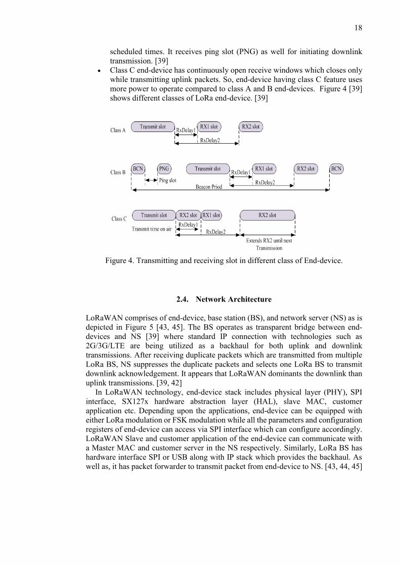
scheduled times. It receives ping slot (PNG) as well for initiating downlink
transmission. [39]
Class C end-device has continuously open receive windows which closes only
while transmitting uplink packets. So, end-device having class C feature uses
more power to operate compared to class A and B end-devices. Figure 4 [39]
shows different classes of LoRa end-device. [39]
Figure 4. Transmitting and receiving slot in different class of End-device.
2.4. Network Architecture
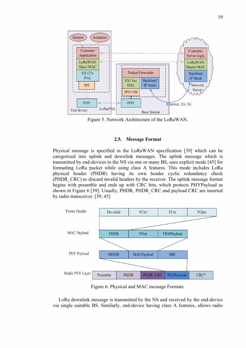
LoRaWAN comprises of end-device, base station (BS), and network server (NS) as is
depicted in Figure 5 [43, 45]. The BS operates as transparent bridge between end-
devices and NS [39] where standard IP connection with technologies such as
2G/3G/LTE are being utilized as a backhaul for both uplink and downlink
transmissions. After receiving duplicate packets which are transmitted from multiple
LoRa BS, NS suppresses the duplicate packets and selects one LoRa BS to transmit
downlink acknowledgement. It appears that LoRaWAN dominants the downlink than
uplink transmissions. [39, 42]
In LoRaWAN technology, end-device stack includes physical layer (PHY), SPI
interface, SX127x hardware abstraction layer (HAL), slave MAC, customer
application etc. Depending upon the applications, end-device can be equipped with
either LoRa modulation or FSK modulation while all the parameters and configuration
registers of end-device can access via SPI interface which can configure accordingly.
LoRaWAN Slave and customer application of the end-device can communicate with
a Master MAC and customer server in the NS respectively. Similarly, LoRa BS has
hardware interface SPI or USB along with IP stack which provides the backhaul. As
well as, it has packet forwarder to transmit packet from end-device to NS. [43, 44, 45]
19
Figure 5. Network Architecture of the LoRaWAN.
2.5. Message Format
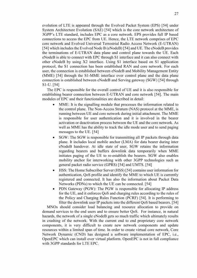
Physical message is specified in the LoRaWAN specification [39] which can be
categorized into uplink and downlink messages. The uplink message which is
transmitted by end-devices to the NS via one or many BS, uses explicit mode [45] for
formatting LoRa packet while using class A features. This mode includes LoRa
physical header (PHDR) having its own header cyclic redundancy check
(PHDR_CRC) to discard invalid headers by the receiver. The uplink message format
begins with preamble and ends up with CRC bits, which protects PHYPayload as
shown in Figure 6 [39]. Usually, PHDR, PHDR_CRC and payload CRC are inserted
by radio transceiver. [39, 45]
Figure 6. Physical and MAC message Formats.
LoRa downlink message is transmitted by the NS and received by the end-device
via single suitable BS. Similarly, end-device having class A features, allows radio

20
packet explicit mode to format downlink messages but there is no CRC to protect
PHYPayload. [39, 45]
2.5.1. MAC Frame Formats
In LoRaWAN, PHYPayload includes MACPayload along with single byte MAC
header (MHDR) and 4 bytes Message Integrity Code (MIC). Before calculating MIC,
MACPayload must be encrypted to carry MAC commands within FRMPayload
portion. Table 2 [39], represents PHYPayload which consists of MHDR, MACPayload
and MIC and shows the number of bits allocated for them. [39]
Table 2. PHYPayload format in LoRaWAN
MHDR MACPayload MIC
MType RFU Major FHDR FPort FRMPayload
Bit# 7 to 5 Bit# 4 to 2 Bit# 1 to 0 7..23 bytes 0..1 bytes 0..N bytes 4 bytes
During transmission, MAC command is not transmitted frequently within
FRMPayload, one block within MACPayload called FPort is being used to indicate
this MAC command while another block called frame header (FHDR) contains short
end-device address (DevAddr). Along with 4 bytes DevAddr, FHDR comprises of
single byte frame controller (FCntrl), two bytes frame counter (FCnt) and 0..15 bytes
frame options information (FOpts) which shows in Table 3. [39]
Table 3. Frame Header format in the MACPayload
FHDR
DevAddr FCntrl FCnt FOpts
4 bytes 1 byte 2 bytes 0..15 bytes
In LoRaWAN, FOpts field is also used to transport MAC commands. MHDR is
implemented based on message types (MType) which are defined by the last three bits
of the MHDR along with RFU and Major (shown in Table 2). Major defines the
message format during attachment procedure and some bits are reserved for future
usage in the RFU field. Table 4 [39] shows different MType values in MAC messages.
[39]
Table 4. Message types in MAC Header field within LoRaWAN
MType value Description
000 Join Request
001 Join Accept
010 Unconfirmed Data Up
011 Unconfirmed Data Down
100 Confirmed Data Up
101 Confirmed Data Down
110 RFU
111 Proprietary

21
2.5.2. MAC Commands
Basically, MAC command is used at network administration, by which LoRa end-
devices interacts with NS on MAC layer. It provides the facilities to check whether the
end-device connectivity is validated for LoRaWAN. And several MAC commands are
exchanged such as DutyCycleReq, DevStatusReq, RXTimingSetupReq etc. to check
the device status, channel conditions, receiver window slot etc. Therefore, MAC
commands being exchanged either in the frame option field or in the FRMPayload.
The FRMPayload consists of FPort with the value of zero when the MAC commands
are presented in it. But, it is always encrypted without MAC commands while frame
option field is used to piggyback MAC commands without using encryption. [39]
2.6. Device Attachment Procedures
LoRaWAN technology provides a secured communication network. The end-device
must be attached to LoRa network in order to start packets transmission. Before
attachment procedure, end-device has to store following information in order to
identify the end-device uniquely, to encrypt and verify network communication and
application data: [39]
A globally unique end-device identifier (DevEUI)
Application identifier (AppEUI)
AES-128 key (APPkey)
To start the attachment procedure, the end-device sends a join request message to
the BS for attaching end-device with LoRaWAN network using Over-The-Air
Activation (OTAA) process. This join message contains not only two identifiers for
identifying uniquely but also an AppNonce [39] which is the unique ID provided by
the NS and it is used by the end-device to generate two session keys i.e. NwSKey and
AppSKey. Once the end-device joins the network, these keys are used to encrypt
messages. After this procedure, BS responds with an acknowledgement of join accept
message which includes end-device address, another nonce, network identifier and the
channel information to be used by the end-device. It is important that these two join
messages are exchanged for every new attachment session in order to get new session
keys. However, another way that could be used to attach with the network is Activation
by Personalization (ABP). In this process, these two session keys are stored directly
into the end-device. [39]
After the successful completion of attachment procedure, end-device should have
following information:
End-device address (DevAddr) contains 32 bit end-device identifier of which
seven bits defines network identifier and the rest of 25 bits is assigned for
network address. [39]
Network session key (NwSKey) is used to calculate and verify the MIC of all
messages. [39]
Application session key (AppSKey) which is used to encrypt and decrypt the
payload of data frames. [39]

22
2.7. Network Security
As security is the fundamental requirement in all wireless communication, it has been
designed into the LoRaWAN security domains by using cryptographic mechanisms.
During end-device authentication within LoRaWAN network, each end-device is
personalized with a unique 128 bit AES key i.e., AppKey and a global unique identifier
i.e., EUI-64 based DevEUI. But LoRaWAN network is identified by using a 24-bit
global unique identifier. However, multiple properties are supported to ensure the
LoRaWAN security such as mutual authentication, integrity protection etc. Mutual
authentication has been established in network security domain between end-device
and LoRa NS. This authentication ensures that only authorized end-device can join
with authentic network during the network join procedure. Hence, there are two
session keys are derived, one (NwkSKey) is for integrity protection of the MAC
commands and one (AppSKey) is for end-to-end encryption of application payload.
The NwkSKey is exchanged in network domain between end-device and NS in order
to verify the LoRa packet. While AppSKey is exchanged in application domain
between end-device and application sever to encrypt and decrypt the application
payload. Figure 7 [40] shows the two keys that are utilized for encryption and
authentication in network and application domains. [40]
Figure 7. Encryption and authentication in network and application domains.

23
3. 5G TEST NETWORK
With the increasing demand for new innovative applications and large number of
devices having extended data rates connected within a network, the 3GPP introduces
EPC, as an all-IP core network architecture [46]. The latest specification of the EPC
architecture enables multiple unique parameters for different access network
technologies like Universal Mobile Telecommunications System (UMTS) [46],
WLAN, non-3GPP access network and more demanding LTE with the use of several
application platforms such as IP multimedia subsystem (IMS) and Internet [47].
Through the adoption of Internet services over IP based communication mechanism,
the LTE increases wireless network throughput with improved latency compared to
the conventional approaches. Moreover, a new communication prototype is
implemented in the wireless operator environments by introducing EPC [46].
Currently, the EPC implementation over virtual server, provides attractive low cost
communication platform for deploying multiple applications in industry, academia,
transportation and healthcare [48]. In order to implement such virtual platform, NFV
and SDN is introduced with the existing EPC core network so as to fulfil the
requirements for future 5G network application for better control and improved
management of network resources [3].
The 5GTN is designed for deploying of the realistic 5G network environment of the
University of Oulu and VTT [3]. Within this network, VTT can test the functionality
of their technologies, tools and application in restricted network environment while
University of Oulu has developed a public network in order to verify and authenticate
user device. 5GTN will offer fully IP-based functionality to form a dynamic and
heterogeneous network platform for R&D purpose as well as testing new applications
and services in real-life scenarios [23]. The current setup of the 5GTN at the University
of Oulu includes for Radio Access Network (RAN) provided by Nokia which is
connected to the Nokia’s EPC at Tampere over the Virtual Private Network (VPN)
connection [3, 23]. For research purposes another virtual based core network
OpenEPC is implemented as second core network in 5GTN. This virtualized testbed
platform is deployed to demonstrate real-life scenarios for future mobile network.
Therefore, this chapter describes the required protocol stacks and functionalities of
OpenEPC and attachment procedure for 3GPP and non 3GPP access network which
leads to understanding of the network architecture and routing path of OpenEPC. The
architectural overview is required to understand the modules and interfaces which are
used in 5GTN, as the aim of the thesis is to integrate the LoRaWAN to the 5GTN.
3.1. Architectural Overview of the 5G Test Network
Instead of using conventional hardware based proprietary network functions,
virtualization makes the transfer of hardware resources to software instances possible.
Network Elements as Virtual Network Functions provides an open testbed for
supporting various software based innovations [7]. The 5GTN will provide a
virtualized platform using number of functions in the network that could be
implemented on top of virtual environment on demand. The current 5GTN deploys a
network infrastructure in such a way that the test network supported RAN can establish
S1 connection by using S1 interface with the core network which is located in Tampere

24
over the VPN switch. This Tampere core network provides Shared Reference Network
(SRN) connection which is used through Internet as a service platform. But the demand
for reducing capital expenditures and increasing the use of core network dynamically
has pushed the network function towards virtualization platform merged with software
application. To achieve these virtualized functions successfully with core network,
NFV has to be deployed which is transferring network functions from hardware
appliances to software based virtualization platform. With virtual environments,
multiple virtual machines can be installed over a single physical machine on top of
hypervisor. Hypervisor is a software platform used to monitor and manage physical
resources for virtual machine as well as it provides virtual environment on which
multiple virtual machines are executed. [3]
With the purpose of using virtualization platform and to overcome the limitation of
using SRN connection through VPN, OpenEPC has been deployed into Oulu Data
Centre (DC) [3, 23] on top of hypervisor within 5GTN as a virtual platform along with
Nokia’s core network at Tampere. In 5GTN, OpenEPC components such as Mobility
Management Entity (MME), Serving and PDN gateway (SPGW), and EPC-Enabler
[48, 49] are deployed as virtual machines running on standard Ubuntu [50] which is
the operating system of the virtual machines and a hypervisor is used i.e., vSphere
ESXi [51] to provide abstraction from the underlying host server hardware in order to
separate physical and virtual resources.
However, a Pico and a Macro cells in 5GTN, are configured keeping in view that
these have to establish S1 connectivity with different core network from different IP
Pools. So, the cells can be provisioned with one core at a time. For example, the cells
are provisioned from OpenEPC IP Pool while S1 connection would be made with
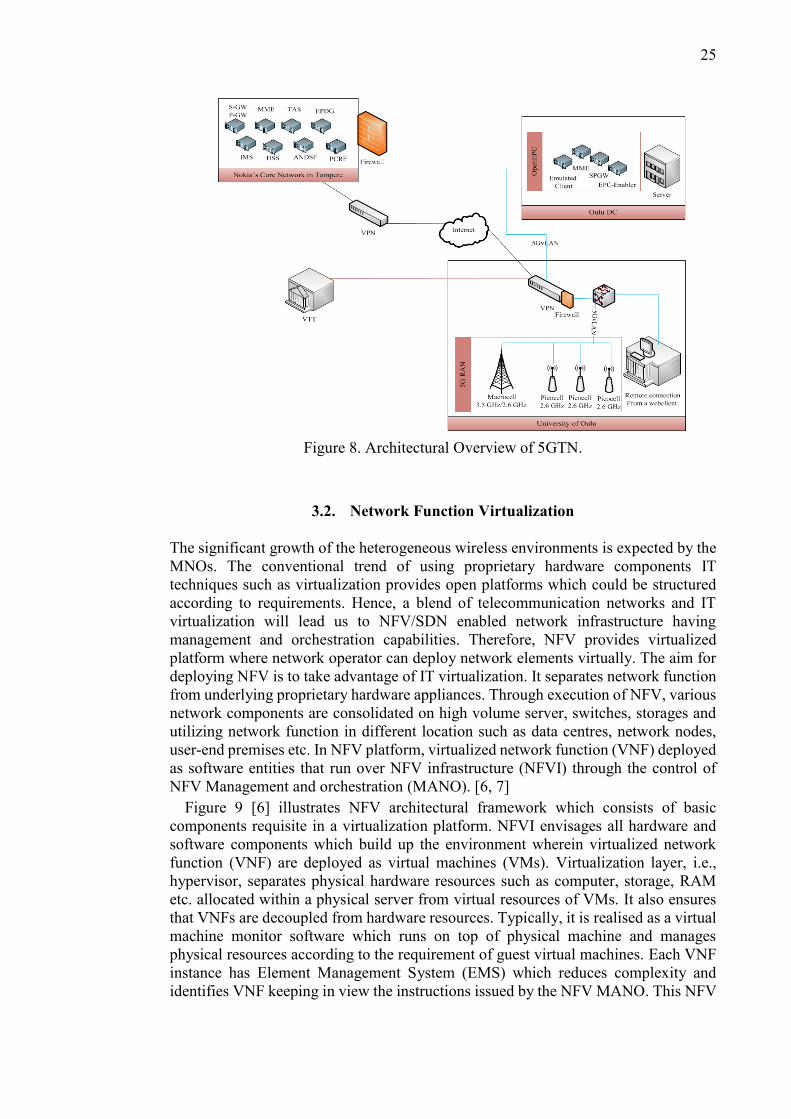
OpenEPC. Figure 8 illustrates a detailed architecture of the 5GTN where OpenEPC is
integrated with 5GTN for research purposes. The test network is currently based on
LTE technology but 5G services and features will be developed upon that basis. This
OpenEPC includes all main EPC functionalities and multiple user equipment (UE) can
be connected to the network over real radio interfaces. The Pico cell or Macro cell is
connected with the 5GvLAN physically, which creates S1 connection to the MME
within OpenEPC where all the OpenEPC components are installed as a virtual machine
(VM) having real prototypes of EPC [52]. For additional information, OpenEPC core
network can also be installed within one physical host machine on top of hypervisor,
as hypervisor detaches the virtual core network from proprietary hardware.
Currently, 5GTN supports Macro and Pico cells where a Macro cell is operating
with both Time Division Duplex (TDD) [53] and Frequency Division Duplex (FDD)
[53] support at 3.5 GHz and 2.6 GHz whereas a Pico cells have FDD support with 2.6
GHz spectrum. The maximum channel bandwidth for a Macro cell can be as high as
40 MHz with a support of both 2x2 and even 4x4 MIMO. While a Pico cell is
configured to have 5MHz channel bandwidth which can be further scaled to 20 MHz
at most. A Macro cell is very sensitive to synchronization as it has only phase
synchronization support [53]. While, a Pico cell has the support for both phase and
frequency synchronization [53]. The synchronization can be done either using NTP
[53] servers or GPS [53] antennas. Finally, yet importantly, a Macro cell is most
suitable for large area coverage while a Pico cell could be used at indoor places i.e.
inside a shopping mall, restaurant, offices etc. with large number of users.
25
Figure 8. Architectural Overview of 5GTN.
3.2. Network Function Virtualization
The significant growth of the heterogeneous wireless environments is expected by the
MNOs. The conventional trend of using proprietary hardware components IT
techniques such as virtualization provides open platforms which could be structured
according to requirements. Hence, a blend of telecommunication networks and IT
virtualization will lead us to NFV/SDN enabled network infrastructure having
management and orchestration capabilities. Therefore, NFV provides virtualized
platform where network operator can deploy network elements virtually. The aim for
deploying NFV is to take advantage of IT virtualization. It separates network function
from underlying proprietary hardware appliances. Through execution of NFV, various
network components are consolidated on high volume server, switches, storages and
utilizing network function in different location such as data centres, network nodes,
user-end premises etc. In NFV platform, virtualized network function (VNF) deployed
as software entities that run over NFV infrastructure (NFVI) through the control of
NFV Management and orchestration (MANO). [6, 7]
Figure 9 [6] illustrates NFV architectural framework which consists of basic
components requisite in a virtualization platform. NFVI envisages all hardware and
software components which build up the environment wherein virtualized network
function (VNF) are deployed as virtual machines (VMs). Virtualization layer, i.e.,
hypervisor, separates physical hardware resources such as computer, storage, RAM
etc. allocated within a physical server from virtual resources of VMs. It also ensures
that VNFs are decoupled from hardware resources. Typically, it is realised as a virtual
machine monitor software which runs on top of physical machine and manages
physical resources according to the requirement of guest virtual machines. Each VNF
instance has Element Management System (EMS) which reduces complexity and
identifies VNF keeping in view the instructions issued by the NFV MANO. This NFV

26
MANO involves three function blocks, virtualized infrastructure manager (VIM),
virtualized network function management (VNFM) and network function
virtualization orchestrator (NFVO). NFVO is in charge of tracking complexity of VNF
and is providing orchestration decisions to VNFM according to EMS. After that VIM
allocates virtual resources within NFVI in order to maintain the required quality of
service. Finally, VNFM manages the lifecycle of VNFs as well as it deploys and
configures new one according to VIM allocation. This NFV architectural framework
is defined by ETSI NFV group at functional level without any indications of a specific
implementation. [6]
Figure 9. NFV architectural framework.
3.3. Software Defined Network
From network point of view, Software Defined Network (SDN) [7] provides
programmable network platform where the control and data planes are decoupled
under the control of centralized software controller. The data plane nodes can establish
a secure TCP connection to the controller. A synchronization protocol for example,
OpenFlow is required for remote connection between control and data plane. SDN
serves NFV by providing programmable connectivity between VNFs and SDN
controls VNF MANO roles remotely in order to manage NFVI functionalities.
Therefore, SDN provides software controllable network having control plane running
on the cloud and data plane deployed as a node within network. As, both SDN and
NFV are two separate technology but these can be merged to deploy a NFV based
infrastructure upon which SDN can be run as a software. [7] Currently, OpenEPC in
5GTN does not have SDN feature. It can be further extended by using OpenFlow
protocol, as OpenEPC supports OpenFlow controller switch. [49]
3.4. Evolved Packet Core
In the contrast to the conventional circuit-switched infrastructure of the mobile
network, LTE has been implemented based on packet-switched schemes. Therefore, it
is possible to provide seamless IP connectivity to the user during mobility. The
27
evolution of LTE is appeared through the Evolved Packet System (EPS) [54] under
System Architecture Evolution (SAE) [54] which is the core network architecture of
3GPP’s LTE standard, includes EPC as a core network. EPS provides full IP based
connections to access the EPC from UE. Hence, the LTE network comprises of EPC
core network and Evolved Universal Terrestrial Radio Access Network (E-UTRAN)
[54] which includes the Evolved Node B (eNodeB) [54] and UE. The eNodeB provides
the terminations of E-UTRAN data plane and control plane towards the UE. Each
eNodeB is able to connect with EPC through S1 interface and it can also connect with
other eNodeB by using X2 interface. Using S1 interface based on S1 application
protocol, the S1 connection has been established RAN and core network. For each
user, the connection is established between eNodeB and Mobility Management Entity
(MME) [54] through the S1-MME interface over control plane and the data plane
connection is established between eNodeB and Serving gateway (SGW) [54] through
S1-U. [54]
The EPC is responsible for the overall control of UE and it is also responsible for
establishing bearer connection between E-UTRAN and core network [54]. The main
modules of EPC and their functionalities are described in detail:
MME: It is the signalling module that processes the information related to
the control plane. The Non-Access Stratum (NAS) protocol at the MME, is
running between UE and core network during initial attachment. The MME
is responsible for user authentication and it is involved in the bearer
activation or deactivation process between the UE and the core network. As
well as MME has the ability to track the idle mode user and to send paging
messages to the UE. [54]
SGW: The SGW is responsible for transmitting all IP packets through data
plane. It includes local mobile anchor (LMA) for data bearer during inter
eNodeB handover. At idle state of user, SGW retains the information
regarding bearers and buffers downlink data temporarily when MME
initiates paging of the UE to re-establish the bearers. SGW also enables
mobility anchor for interworking with other 3GPP technologies such as
general packet radio service (GPRS) [54] and UMTS. [54]
HSS: The Home Subscriber Server (HSS) [54] contains user information for
authentication, QoS profile and identify the MME to which UE is currently
registered and connected. It has also the information about Packet Data
Networks (PDNs) to which the UE can be connected. [54]
PDN Gateway (PGW): The PGW is responsible for allocating IP address
for the UE, and it enforces QoS and charging rules according to the rules of
the Policy and Charging Rules Function (PCRF) [54]. It is performing to
filter the downlink user IP packets into the different QoS based bearers. [54]
MNOs should consider load balancing and resource allocation to provide on
demand services to the end users and to ensure better QoS. For instance, in natural
hazards, the network of a single eNodeB gets so much traffic which ultimately results
in crashing of the network. With the current end to end proprietary core network
components, it is very difficult to create new network components and update
resources within a limited span of time. In order to create virtual core network, Core
Network Dynamic (CND) has designed a software implementation of EPC, i.e.,
OpenEPC which can install over virtual platform. OpenEPC is not in full compliance
with 3GPP standards for LTE EPC.

28
3.5. OpenEPC
The existing LTE access network leads toward the network infrastructure into the
software defined virtualized platform for more control on each individual core network
components by using open interfaces. OpenEPC implements such a virtualized
prototype along with core network functionalities and interfaces according to the
3GPP’s EPC standard. These functionalities enable the control over core network
remotely with separating control and data plane. OpenEPC comprises functionalities
such as authentication and authorization, mobility management, policy and charging
rules according to the access network like LTE, 3GPP, trusted non 3GPP, and
untrusted non 3GPP. The PCRF module is responsible to establish the rules and
charges for each user and service in real time. According to deployment of OpenEPC
in 5GTN, the SGW and PDN-gateway (PGW) functions are collocated in serving and
PDN gateway (SPGW). The virtual MME performs control plane function in the LTE
access network and SPGW ensures PDN connectivity over data plane for routing and
forwarding user data packet from and to the eNodeB. The HSS database stores user
information for authentication and authorization. OpenEPC uses both GPRS
Tunnelling protocol (GTP) and Proxy Mobile IP (PMIP) that enable mobility
management solution for the core network. [52] All components and functions are
elaborated in sections 3.5.1 and 3.5.2.
3.5.1. OpenEPC as a Core Network
As mentioned previously, OpenEPC supports LTE access network as well as non
3GPP access network. All communication functionalities, protocols, interfaces and
components have been deployed to be part of OpenEPC in separate modules according
to access network demands. In OpenEPC, each module has its own API for interacting
with other EPC components as well as with external components at different
communication levels. It also provides console for configuring interfaces and modules
dynamically. [48] OpenEPC provides PCRF over management (mgmt.) interface
along with QoS enhancement mechanism based on individual subscription profile. In
OpenEPC, eNodeB establishes S1 connection with MME over net_d and SPGW also
supports net_d interface to create GTP tunnel with MME during attachment procedure.
But UE connects to the cells on an_lte interface which assigns IP to the user on net_c
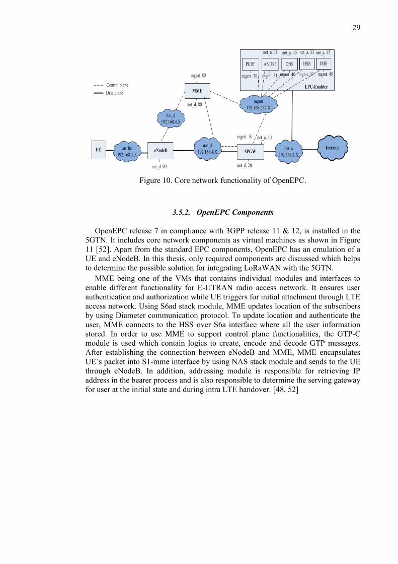
IP Pool. Figure 10 [48] illustrates the OpenEPC control and data plane over different
interfaces. According to this, ‘net_a’ is the actual PDN interface for accessing the
Internet. The ‘net_d’ is used as 3GPP radio access backhaul which connects eNodeB
with EPC core network on control plane while ‘mgmt.’ is the management interface
which enables signalling for individual access to different machines within OpenEPC.
[48, 49]
29
Figure 10. Core network functionality of OpenEPC.
3.5.2. OpenEPC Components
OpenEPC release 7 in compliance with 3GPP release 11 & 12, is installed in the
5GTN. It includes core network components as virtual machines as shown in Figure
11 [52]. Apart from the standard EPC components, OpenEPC has an emulation of a
UE and eNodeB. In this thesis, only required components are discussed which helps
to determine the possible solution for integrating LoRaWAN with the 5GTN.
MME being one of the VMs that contains individual modules and interfaces to
enable different functionality for E-UTRAN radio access network. It ensures user
authentication and authorization while UE triggers for initial attachment through LTE
access network. Using S6ad stack module, MME updates location of the subscribers
by using Diameter communication protocol. To update location and authenticate the
user, MME connects to the HSS over S6a interface where all the user information
stored. In order to use MME to support control plane functionalities, the GTP-C
module is used which contain logics to create, encode and decode GTP messages.
After establishing the connection between eNodeB and MME, MME encapsulates
UE’s packet into S1-mme interface by using NAS stack module and sends to the UE
through eNodeB. In addition, addressing module is responsible for retrieving IP
address in the bearer process and is also responsible to determine the serving gateway
for user at the initial state and during intra LTE handover. [48, 52]

30
Figure 11. Components within OpenEPC.
Another important virtual machine is SPGW which includes a serving gateway (S-
GW) and a PDN gateway (P-GW) functionalities with required interfaces and protocol
stacks. The control plane of SPGW can be realized by using Local Mobility Anchor
(LMA) module, which allocates IP address for users while user initiates attachment
request to connect with EPC. But it is important to note that, this IP address for each
user must be provisioned from clients IP address pool before assigning. The IP
allocation can be done using DHCP module within SPGW which then forwards
address to the users. In OpenEPC, PDN connectivity can be established into SPGW
gateway over both GTP and PMIP, as the functional module of SGW and PGW are
placed in a single virtual machine. As SPGW includes data plane functionality, it
supports routing modules and transmits data packets to the Internet gateway through
SGi interface for uplink traffic. It also includes gw_binding module which has all the
information related to gateway binding, access point name (APN), bearer information,
policy and charging information, mobility access information etc. According to PCRF
rules, Policy and Charging Enforcement Function (PCEF) module enforces QoS
values within SPGW over Gx interface depending on subscribers and services
specifically when new subscriber attached and requested for accessing different
services. [52]
EPC-Enabler includes functionalities such as Domain Name System (DNS) [53],
Network Address Translation (NAT) [53], PCRF, HSS, Access Network Discovery
and Selection Function (ANDSF) [52], SMS Router, Authentication, Authorization
and Accounting (AAA) [53], Serving-Call Session Control Function (S-CSCF) [53],
Proxy-CSCF (PCSCF) [53], Interrogating-CSCF (I-CSCF) [53]. The DNS in each
virtual machine resolves the DNS queries within the OpenEPC network where the
NAT translates IP address into another by modifying network address information in
IP network. All VMs can be accessed through root connectivity within OpenEPC.

31
However, IMSI (International Mobile Subscriber Identity) should be registered into
HSS database for provisioning subscribers. Without registration, UE cannot connect
with core network. From user data repository (UDP) which is the central user
information database, HSS issues a query for user information and stores these
information temporarily in cache memory. After that HSS acts as a complete user
database and performs authentication and authorization with MME entity [52]. The
module ANDSF is located in EPC-Enabler, which transmits the indicators over S14
interface to the UE to switch among different access networks on priority basis. It is
also responsible for default IP route before the Internet gateway during packet
transmission. Another important module PCRF which is responsible for enforcing the
charging and policy rules and for allocating resources for each established bearer based
on subscriber’s profile. [52, 53]
3.5.3. LTE access network signalling in a nutshell
OpenEPC allows 3GPP and non 3GPP trusted and untrusted access network to be
connected with LTE evolved packet core network [52]. It also enables operators to
provide fast 4G data speeds as well as reducing cost with utilizing virtualized network
platforms [52]. However, OpenEPC has the capability to support multiple protocols
for communicating over different access network. Both GTP and PMIP are used for
PDN connectivity over LTE access network, data is encapsulated through UDP for
GTP tunnel while IP tunnel is created for PMIP. [48]
The interfaces of OpenEPC and their purposes are described in Table 5 [72].
Table 5. Interfaces and their functions to access both 3GPP and non-3GPP access
network
Interfaces Purposes
S1-mme Control plane interface between E-UTRAN and MME.
S1-U Interface between E-UTRAN and SGW for creating bearer user tunnel.
S5 Interface between SGW and PDN GW for providing user plane tunnelling and tunnel
management. Also, it is utilized for SGW relocation due to UE mobility.
S8
It is used as an inter-PLMN (Public Land Mobile Network) interface for providing
user and control planes between the SGW and the PGW.
S6a Interface between MME and HSS. It transfers subscription and authentication data for
authenticating/authorizing user access to the EPC.
S11 Interface between MME and SGW
Gx Interface between PGW and PCRF for providing QoS policy and charging rules from
PCRF to the PCEF in the PGW.
SGi Interface between PGW and packet data network for accessing public or private packet
data network of an external operator or an intra operator.
S2b Interface between ePDG and PGW for providing the user plane with related control
and mobility support between ePDG and the Gateway
A typical attachment procedure is described in Figure 12 while LTE access
network is used for establishing S1-mme connection between eNodeB and MME over
S1-mme interface. According to MME configurations, eNodeB needs to be configured
by using specified IP pool which is allocated for OpenEPC in 5GTN. The purpose of
eNodeB configuration is to transfer the configuration information of RAN from
eNodeB to MME. Attachment procedure comprises of two messages, attachment

32
request from eNodeB to MME and attachment request acknowledge from MME to
eNodeB over S1-mme interface [55, 56].
Figure 12. Attachment Procedure between eNodeB and MME.
Figure 13 [55] shows the overall attachment procedure for LTE user. After
establishing S1-mme connection successfully between eNodeB and MME, the UE
initiates attachment procedure by sending RRC connection request to eNodeB over
LTE access network. After receiving acknowledgement of the RRC request from
eNodeB, UE sends attachment request and PDN connectivity request through NAS
protocol to the MME via eNodeB. Then MME performs authentication and
authorization by sending authentication request to HSS. According to current status of
user, MME updates location of the subscriber to HSS by sending update location
request that includes PLMN identifier i.e., mobile network code (mnc) and mobile
country code (mcc). Afterward MME creates GTP-C session request with SPGW (in
OpenEPC) and SPGW triggers charging control request to PCRF. Upon receiving GTP
session response, MME responses accordingly with Attachment Accept towards the
UE. Thus, attachment has been done with sending Accept complete message and
bearer context accept message. [55, 56]

33
Figure 13. Signalling flow diagram of attachment procedure.
3.5.4. Signalling route over Non-3GPP
OpenEPC is designed to support variety of access network technologies, ePDG has to
be deployed for deploying non 3GPP access network on increasing non-3GPP
connectivity demand as shown in Figure 14 [57]. Currently, OpenEPC in 5GTN, does
not have ePDG virtual instance. As MME establishes link over LTE access network,
ePDG treats non-3GPP access network as untrusted and it creates IPsec tunnel for
secure data transmission. The reason of using IPSec tunnel is to encrypt and secure IP
communication by transmitting IP packet within communication session. In OpenEPC
release 7, ePDG includes Mobility Access Gateway (MAG) function having PMIPv4
or PMIPv6. Attachment of non-3GPP user to core network is done through the request
of IP address over DHCP module which is integrated within ePDG. At the same time
ePDG establishes IPSec tunnel according to IP address assigned for particular
subscriber by the standard network IP Pool for secure data communication between
user and ePDG. After that data packets are forwarded to PDN-G which is connected
with ePDG over S2b interface. In addition, Bearer Binding and Event Reporting
Function (BBERF) module is also included in ePDG for policy control as to provide
requested QoS and priority parameters associated to subscribers. This module enforces
its QoS rule according to PCRF module over Gxb interface. As to completely
differentiate between 3GPP and non-3GPP users, different interfaces are utilized, e.g.,
a non 3GPP user will use the ‘an_wifi’ interface which would then connect it to ePDG
directly. [57]

34
Figure 14. OpenEPC Components and Interfaces.

35
4. LORAWAN INTEGRATION WITH THE 5GTN
As the number of end users with heavy bulks of data is increasing day by day, the
existing LTE infrastructure will no longer be capable to process such a huge data traffic
outburst. At the same time, NGMN [2] is expected to bring diverse IoT applications
by integrating massive number of M2M communication devices with the existing
infrastructure over the Internet. It is expected that LPWAN will bring a major
evolution to existing infrastructure to process such an IoT embedded ecosystem by
handling huge data traffic with low latency. [10]
The existing LTE networks do not have the LPWAN integration support. As part
of the future roadmap, SDN and NFV are expected to bring a major network evolution
in existing LTE EPC from the core network perspective. The virtualization of LTE
core network components running as virtual instances in a cloud, changes the
conventional trend of using proprietary hardware components. Also, variety of IoT
applications could be merged with this virtual core instance to make a possibility to
get it integrated to be part of the same cloud.
Currently, 5GTN is compatible to support LTE core network, which is being
deployed for research purposes as mentioned previously. This test network also
provides virtual core network based on 3GPP LTE infrastructure. The UE can connect
with this core network by using LTE interface. This virtual platform is also open to
integrate IoT applications. Therefore, this could be utilized for developing IoT enabler
network by integrating LPWAN. LPWAN could be scaled to make a possibility to get
it integrated to be part of the 5GTN.
Among LPWAN technologies, the LoRaWAN is becoming more interesting for
research and industrial communities [1] because of the long-range communication,
ADR and due to the simple network architecture. Therefore, LoRaWAN is chosen to
implement the integration scenario practically in this thesis work. Several integration
possibilities will be discussed in this Chapter, in which one real implementation
scenario will be discussed in Chapter 5.
4.1. Integration at a Glance
The question of adding IoT features to a 5GTN network by using LoRaWAN is still
ambiguous. However, different levels of integration are already being discussed by
several research projects in telecommunications community around the globe.
LoRaWAN can be integrated with cellular network by transmitting LoRa packet using
eNodeB, according to [58]. As proposed in [58], LTE modem having the capability of
receiving LoRa packets from end-devices. The modem also supports Subscriber
Identification Module (SIM) card [58]. Therefore, it can collect data from the LoRa
end-device, further forward to the core network through eNodeB. There is an
adaptation layer within the LTE modem between LoRa and LTE UE [58]. LoRa
packets transmitted by an end device might be received by multiple BS. The NS
receives multiple duplicate copies of same packets coming from multiple BS.
LoRaWAN uses an unlicensed spectrum [58] for transmission, while LTE uses
licensed spectrum. Such integration degrades performance by consuming more
spectrum which would then result in more network latencies. The problem is tackled

36
by creating an interface and some algorithm schemes that are discussed in detail in
reference [58].
LoRa NS can be performed as a virtual instance on the cloud platform by
implementing network server functionalities, the detailed explanation is found in [43].
According to [43], LoRa NS is implemented on the Openstack cloud where all
management operations have been done by using Openstack [77] APIs. OpenStack
must be installed on an ubuntu operating system which provides with an IP address for
horizon [77] and keystone [77] respectively. Using the web client, we can reach the
OpenStack dashboard [77]. Using the dashboard two networks could be created, one
is for external networking and the other one is for internal networking. The internal
network enables primarily the inter VM communication and the external network is
used for communication with the LoRa BS. In the dashboard, using the Nova [77] as
an availability zone we can create as much VMs as required. [43]
The 5GTN is a test network for industry and academia, which can support all access
networks. Therefore, it could be an option that LoRaWAN could be established a
connection with 5GTN’s core by using access network. As discussed in Chapter 2,
LoRaWAN has its own network to collect data from end-devices and it can use, e.g.,
WLAN or 3G as the backhaul to transfer data to its own server. Similarly, LoRaWAN
could utilize its own network as the front haul and access network as the backhaul.
This access network could be either 3GPP or non-3GPP to establish a connection
between LoRaWAN and 5GTN’s core. To implement such a platform, either 1)
LoRaWAN needs to support same protocols and interfaces the testbed network has or
2) test network needs to enable such connection support.
As, 5GTN has virtual core network with virtualized functions, LoRaWAN could be
deployed as a virtual instance which can be capable to connect with virtual components
in 5GTN. If this virtual LoRaWAN supports MANO, multiple data planes can be
created virtually on demand to control IoT data traffic. This virtual instance could be
running on and processing LoRa packet either in the same server where the 5GTN
virtual core does or in different server. However, the LoRaWAN could be installed as
a virtual instance in the same cloud, then it could be utilizing same data route to
transmit LoRa packet. Otherwise, it needs to establish a connection between virtual
LoRaWAN and core network to be part of the 5GTN. However, any entity of the
LoRaWAN could be used to implement virtual LoRaWAN infrastructure. From RAN
to core network level, several potential key ingredients are identified and required to
implement such kind of network platforms. Still it is an open of question whether
connection between them could be made virtually, physically or via API platforms.
4.2. Levels of Integration
It is expected that the upcoming 5G technology will enable support for numerous use
cases based on innovative applications by using multi-purpose virtual core network.
5GTN has a vEPC where all network components are deployed virtually based on
ETSI’s NFV. To build a testbed which could support IoT use cases in future,
LoRaWAN could be connected physically to a network so that it could establish
connection over a particular vLAN to a virtual LTE core network component.
However, physical connection could be made with RAN as well. RAN forms the major
part in mobile networks which consists of radios involved in data transmission and

37
reception. Future mobile networks are expected to bring major changes in the existing
radios in order to add IoT functionalities. Therefore, RAN could be another option to
integrate LoRaWAN with the 5GTN, but the connection could be established via
ethernet, seamless or APIs. In this Chapter, number of possibilities are discussed which
could make LoRaWAN part of a 5GTN. All the integration scenarios will be discussed
theoretically on state-of-the-art basis, yet a single integration scenario will be chosen
and discussed later in details along with its practical implications.
4.2.1. LoRaWAN as an Access Network
The virtual core network based on 3GPP prototype implementation has multiple access
network support, be it Wi-Fi and WiMAX for untrusted/trusted non-3GPP or 2G/ 3G
networks. When it comes to LoRaWAN integration with the core network level, it
seems that using 3GPP LTE access network is undefined due to the absence of S1
protocol stack in LoRaWAN at this stage. Yet, other non-3GPP trusted or untrusted
access network could be used to connect LoRaWAN with core network.
For example, LoRa BS could access OpenEPC core network (5GTN’s core) and get
authenticated as untrusted non-3GPP networks. The authentication for establishing
such a connection is done in the AAA server by making use of the standard diameter
protocol. SAE provides with the ePDG for such connections to have an IP security
(IPSec) tunnel between the UE and ePDG. Likewise, OpenEPC has an ePDG VM
which could be configured to use IPSec for untrusted access network to connect
LoRaWAN as a UE in this case. In order to have such an IPSec support, ePDG make
use of open source strongswan [20]. But, LoRa BS does not have the required IPSec
support so any physical device which can provide such a tunnel could be utilized here
e.g. a VPN switch. Moreover, the ePDG machine should have GTP/PMIP support for
IPv4 addressing which the OpenEPC’s ePDG does have. The LoRa BS should act as
an IPSec client sending initiation request using the Internet Security Association and
Key Management Protocol (ISAKMP) [73] to the IPSec server at the ePDG machine.
The ePDG then sends authentication request to the AAA server via diameter protocol.
Thus, at core network level, LoRaWAN (using LoRa BS) could be integrated as an
access network with ePDG virtual instance running as a vEPC core network
component as shown in Figure 15.
Figure 15. LoRa BS integrated with 5G testbed Core network.

38
4.2.2. Connecting LoRaWAN to 5GvLAN
To develop integration scenario in such a way that the connection could be made
directly with 5GvLAN while OpenEPC is installed over 5GvLAN. If connection is
possible to the same 5GvLAN which can be provided an IP address within OpenEPC’s
IP pool. If the IP pool is defined from another subnet for LoRaWAN, it gets IP address
from that IP pool and forwards the packets without any interruption of OpenEPC core.
OpenEPC also includes programming model implemented by Representational State
Transfer-API (REST-API) [49] as well as Java Script Object Notation-Remote
Procedure Call (JSON-RPC) [49] protocol for OpenFlow controller extensions,
enabling network-aware services and Core Network enhancements for networks.
Hence, API could be an option to implement integration scenario without any physical
connection. The connection of LoRaWAN with 5GvLAN by using switch as shown in
Figure 16.
Figure 16. Integrating LoRa BS with 5GTN via 5GvLAN.
4.2.3. LoRaWAN being a part of LTE-UE
LoRaWAN could be made a part of an LTE UE to send packets all the way to its
network server on the Internet using LTE data plane path. This could be achieved by
introducing an LTE module which would have both LTE and LoRaWAN protocols
and interfaces support. This module acts like LTE UE which could establish an S1
connection with the eNodeB as part of the LTE signalling as well as it will request for
GTP tunnel creation. Once the connection is established, the module will start sending
packets to the Serving and PDN Gateways as part of the LTE data plane.
Figure 17 shows the possibility of connecting LoRaWAN with 5GTN. However,
this integration could be made by integrating a module which would have LoRaWAN
support and S1 protocol support. Therefore, this module can receive packet from LoRa
end-device as well as transmit to the LoRa NS by using LTE access network in 5GTN.
The integration could be possible in another way if this module would have non-3GPP

39
access network support i.e. Wi-Fi/Wi-MAX. This non-3GPP access network could be
utilized to establish the connection between LoRaWAN and 5GTN.
Figure 17. LoRa BS being a part of LTE-UE.
4.2.4. LoRaWAN being part of eNodeB
IoT being an emerging application in Future Mobile Networks, it is expected to bring
major changes in existing LTE Radio. LoRaWAN supportable gateway could be
integrated within the eNodeB. Therefore, eNodeB would be capable to receive and
transmit LoRa packets along with LTE’s user traffic. The Figure 18 shows the
integration view of LoRa BS being part of eNodeB. For such integration, LoRa BS is
incorporated within 5GTN eNodeB which requires a modification to hardware of
eNodeB. In this set-up, LoRa end-device communicates with the 5GTN’s eNodeB
having a hardware which has the capability to receive those packets and process it
further to the NS using the data plane path via core network.

40
Figure 18. LoRa BS being a part of eNodeB.
4.2.5. LoRa Network Server on OpenStack
Currently, mobile network infrastructure is arranged to be compatible within cloud
platform by making the network components virtual so that the network becomes
global. If the IoT related application is served by MNOs, this could be easy in the
application perspective. For this purpose, virtual instance of the LoRaWAN can be
implemented in the MNO’s cloud. As proposed in [8], this can be an option to integrate
LoRaWAN with the 5GTN.
In order to integrate LoRaWAN with 5GTN, Openstack cloud platform could be
utilized similarly to [43]. As, OpenEPC has already been installed on the virtual server,
LoRaWAN NS could be implemented on the Openstack platform which is already
running over that virtual server. In this virtual environment, NS functionalities could
be classified and defined within a single VM or multiple VMs. The advantage of using
such Openstack platform is to deploy multiple VMs as required. Figure 19 shows the
general ideal to implement LoRaWAN as a virtual instance on Openstack platform by
using dashboard.
Figure 19. LoRa NS virtualization on OpenStack.

41
5. IMPLEMENTATION
The IoT applications with their diverse implications is an emerging evolution and is
changing the conventional approaches of, e.g., implementing automation and smart
use cases. Imagine thousands of sensor nodes transmitting sensor data to a gateway
which itself is integrated with a mobile network infrastructure using the eNodeB. The
eNodeB then uses the same control and data plane to get authorization and process
data traffic respectively. Assuming that the EPC is capable enough to handle bulks of
traffic from those sensor nodes and transfers data to the corresponding servers
operating in an IoT Cloud. The data then can be used to trigger any actions depending
on the use cases. So to speak, out of several integration possibilities, LoRaWAN can
be integrated with the 5GTN as a LTE UE by utilizing ‘combined attach procedure’
[59]. This integration scenario is implemented to merge the ideas from several
possibilities by using different LoRa BS. Like any normal UE, LoRaWAN can connect
with MME via eNodeB on the control plane and transmit traffic (encapsulated into
NAS) to PDN gateway on the data plane as explained in Figure 13. This chapter will
go through the detailed description of LoRaWAN integration with the 5GTN
practically. For further performance evaluation of real time packet transmission to IoT
cloud, it can be utilized for diverse IoT applications purposes.
5.1. Integration Scenario
The 5GTN provides a PoC testbed solution to enable IoT application integration with
it by utilizing different radio technologies. In addition, the 5GTN testbed integrates
multi diverse IoT gateway with its infrastructure, which enables to test and unify
heterogeneous IoT devices as proposed in [3]. This IoT gateway supports various data
transfer protocols like HTTP, CoAP and it has support for several interfaces for
collecting data and distributing it further to other entities and cloud platform. [3] The
5GTN comprises of a service core network having variety of applications as well as it
deploys an open network at University of Oulu [3], it can be utilized to develop and
evaluate the LoRaWAN integration scenario for real time IoT applications in future
mobile network.
Based on a cloud concept, LoRaWAN is processing data and transferring it then to
the IoT cloud platform using the 5GTN. This network provides data plane route as a
wireless backhaul to the cloud. Hence, LoRaWAN uses its own radio technology to
receive data from end-devices and transmits data to the cloud based on MQTT protocol
by utilizing cellular network. This M2M connectivity environment, for enabling IoT
applications, is provided by the MultiConnect Conduit [60] gateway. Having LoRa BS
and NS functionalities, MultiConnect Conduit allows wireless interfaces support and
provides application tools so that, it can be configured according to IoT use cases.
To support a new innovative solution such as integrating LoRaWAN with the
5GTN, MultiConnect Conduit provides suitable programmable and configurable
gateway platform that can be utilized for implementing integration scenario and
developing IoT applications. This gateway is specifically designed for enabling M2M
communications within wireless sensor environments. So, it supports different
protocols to enable LoRaWAN functionalities and cellular network connectivity.
MultiConnect Conduit with its accessory provides a solution based platform to develop

42
applications that utilize LoRaWAN. The Conduit comprises of LoRa BS and NS
functionalities where it supports LoRa mCard to operate either on 868 MHz or on 915
MHz bandwidth [60]. Apart from that, it can be deployed as part of any existing
cellular network to connect eNodeB by installing SIM card or using Ethernet backhaul.
[60] The network architecture is illustrated in Figure 19 after integrating Conduit with
5GTN and transmitting packets successfully to the ThingWorx via 5GTN cellular
network. Thus, Conduit publishes the data which is received from end-device and the
mosquitto MQTT broker receives that data and publishes to the specified mosquitto
client i.e., ThingWorx according to ‘topic’. ThingWorx can also subscribe the data to
the Conduit via MQTT broker. The overall procedures for integrating Conduit with
5GTN is explained in section 5.2.
Figure 19. Network architecture of integrating LoRaWAN with the 5GTN.
5.2. MultiConnect Conduit
MultiConnect Conduit introduces a new embedded solution to plug in multiple
applications for IoT use cases. It is developed by Multitech and it provides several
accessory card (mCard) such as MTAC-GPIO, MTAC-MFSER, MTAC-LoRa,
MTAC-ETH [60] for different purposes as well as it has the ability to install the mini
SIM card, micro SD card etc. [60] As for integration purpose LoRaWAN mCard has
been installed which allows connecting thousands of sensor nodes or appliances. It
allows two antennas in order to support 4G LTE backhaul [60].
Moreover, LoRa radio technology is supported within MultiConnect Conduit by
installing MTAC-LoRa mCard. This mCard provides long range RF support according
to Semtech’s LoRa radio technology and it can also be enabled to establish a
connection between end-device and cloud. The Conduit has MTAC LoRa antenna
which is polarized vertically and this LoRa antenna has 3 dBi gain with Omni

43
directional radiation feature. When installing this mCard within the Conduit, the power
supply needs to be disconnected to avoid undesired situation. There are two mCard
slots AP1and AP2 where either of them can be chosen for installing this card. [60]
Within the Conduit, LoRa network server can be configured to support 868 MHz
and 915 MHz ISM bands having maximum seven frequency sub-bands. For security
purpose, this network server can be encrypted by using username and password. It is
important to configure Network ID (NetID) and corresponding Network Key while
enabling network server functionality. The NetID should be placed on ‘eui’ as a form
of 8 hexadecimal digit and Network key should be a 16-hexadecimal digit. Before
configuring the network server, we need to create LoRa directory and copy the LoRa
network server configuration file from the repository by using following commands:
[60]
mkdir /var/config/lora
cp /opt/lora/lora-network-server.conf.sample /var/config/lora/lora-network-
server.conf
After modifying the setting as required, the system needs to be restart. After
configuring LoRa NS, LoRa end-device can be found by using following script, lora-
query –n [60]. LoRa NS configuration and number of joining node are viewed in
Figure 20.
Figure 20. LoRa NS configuration and node query.
5.2.1. Provisioning to Access Terminal Interface via Ethernet
MultiConnect Conduit provides both options i.e. either using Conduit AEP or mLinux
interface to configure LoRaWAN technology, setting up cellular network and
provisioning the root access. Conduit has Secure Shell (SSH) [61] access on mLinux
interface by which we can create an SSH tunnel from any console. Conduit then can
be accessed by using both AEP or mLinux interfaces. [60, 61]
Once MultiConnect Conduit is connected in a setup to access terminal interface via
Ethernet, network interface of the PC needs to be configured to set static IP address
within 192.168.2.2 to 192.168.2.254 where Conduit is connected. After assigning
static IP to the interface, network interface gets IP within same IP pool that enables to
access the Conduit terminal. The default IP address of the terminal is 192.168.2.1 with
default username and password as admin [60]. On the other hand, Conduit terminal

44
can be accessed by using AEP interface with same default IP address and credentials
after creating SSH tunnel [60].
5.2.2. Receiving packets on the Node-red
MultiConnect Conduit displays packets being transmitted by LoRa end-device by
using mosquitto_sub –t lora/+/up or mosquitto_sub –t lora/+/+ -v [60]. Conduit
provides an application such as Node-red [62] that can also be used to see the packet
payload including channel information, SNR, device eui etc. Node-red is a
programming tool for modelling a platform by using browser-based flow editor. It can
be deployed on a variety of environments to transmit packets directly to a particular
cloud. For enabling the Node-red, it should be launched at https://192.168.2.1:1880/.
[60] ‘LoRa’ from the input block and ‘debug’ from the output editor should be
connected together on the node-red platform as shown in Figure 21. The information
is retrieved by clicking the debug option in the Node-red. LoRa packet is then observed
on the Node-red platform. [62] It is possible to transmit multiple packets from different
sensor node simultaneously which is differentiated by device ‘eui’.
Figure 21. Node-red configuration and packet received.
5.2.3. Point-to-Point Protocol
In general, Point-to Point Protocol (PPP) [63] is an encapsulation protocol to establish
a point to point connection directly between two nodes over Internet. After establishing
PPP connect between two nodes, IP traffic is transmitted across this connection.
MultiConnect Conduit has already PPP configuration file to establish PPP connection.
By using default setting, ppp daemon (pppd) [64] is used along with kernel PPP route
table to establish and maintain PPP connection with other system (called peer
connection) and it also negotiates IP address with each end of the connection link. [64]
The ttyname, a serial port being used in order to communicate with the peer, is set
to dev/modem_at0 as default in the device. Having specified the nodefaultroute in
ppp/options, the default route is established which would use peer as the gateway once
the IPCP negotiation is performed. The pppd asks peer to send packets keeping in view
the maximum receive unit (mru) and maximum transmission unit (mtu) values. The

45
value should be between 128 and 16284 with a 1500 default for mru and mtu
respectively. The call name, used to trigger an attachment, reads options from
/etc/ppp/peers/call name. The Conduit has ‘lvw2_chat’ as a file for configuring APN
for particular operator, which is realized by the pppd call lvw2 command to establish
ppp connection. The ppp0 gets an inet address along with a p-t-p address after
successful attachment where the inet address creates a tunnel for traffic to/from the
Internet to/from the Conduit. But the p-t-p is for Conduit 10.64.64.64 which is the
address of a remote machine used as a default gateway for IP packets routing. [63]
5.2.4. WAN Connection Establishment
MultiConnect Conduit uses ‘PPP’ protocol as a part of WAN connectivity to build up
a cellular connection over ppp0 interface. In order to achieve it, the ppp link must be
configured and initiated. Once ‘PPPD call’ is executed then like a standard LTE
terminal, MultiConnect Conduit establishes an RRC connection to the LTE radio. [60]
The 5GTN has 2.6GHz Pico cell which is connected to a Nokia based EPC over
5GvLAN (in Tampere). This Pico cell stays connected to this core having established
an S1 already with the MME. Initially 5GTN’s SIM card is inserted in the device. The
Conduit is then configured to the respective PLMN values (which in case of 5GTN is
MNC244 and MCC027) and APN settings (which in case of 5GTN is dmz-ferrari)
using the ‘lvw2_chat’ and ‘ppp_chat’ configuration files. Afterwards, using the
terminal’s console which in practice is an ‘openwrt system’ (a Linux OS for embedded
systems), ‘pppd call lvw2’ is executed [60]. The device hence triggers an S1
connection to the closest eNodeB which then creates the required bearers as part of the
LTE signalling and data plane creation. The complete S1 connectivity is explained in
detail in Figure 13. Once the attach request is completed, the device gets an IP address
from the PDN gateway and also the respective DNS IP addresses (shown in Figure
22). As a result, the device is now connected to the ‘Internet’ using one of 5GTN’s
core where the NAT is performed within the core for address resolution outside the
network.

46
Figure 22. PPP Connection Established with Nokia’s EPC at Tampere Core.
Similarly, the connection is also established using OpenEPC (5GTN’s virtual EPC)
which is connected to the RAN over 5GvLAN. Basically, one of the Pico cell stays
connected to 5GvLAN thus establishing an S1 connection with the OpenEPC’s MME.
Now using OpenEPC SIM card, the APN and PLMN values are changed accordingly.
In this case, MNC001 and MCC001 are the PLMN values whereas ‘default’ is the
APN name. Having configured the device, we triggered an attachment request to
OpenEPC which upon success provides the device with an IP address from ‘net_c’ IP
Pool (the topology is explained in detail in OpenEPC sections of Chapter 3). Contrary
to the 5GTN, the device always gets the same IP address while using a particular IMSI
which leads us to a conclusion that in case of OpenEPC, every IMSI has a particular
IP address already provisioned in the EPC. Figure 23 shows the PPP connection with
OpenEPC.

47
Figure 23. PPP Connection Established with OpenEPC.
5.2.5. Message Queue Telemetry Transport protocol
With the increase in IoT applications, the ways of implementing the use cases
including massive number of devices is also increasing exponentially. LPWAN such
as LoRaWAN enables such IoT use cases by providing its own sensor nodes which
are usually being programmed to sense the phenomena and to send the corresponding
data to the cloud over the Internet. MQTT [65] is a protocol for enabling such IoT
connectivity, which is designed as an extremely lightweight messaging transport
protocol. Primarily, it is suitable for connecting sensor nodes with remote locations to
a broker (server) via low bandwidth and unreliable network. It is targeted to ensuring
reliability and assurance to some extent for transmission over unreliable network.
These principles make this protocol ideal for M2M communications. [65] To establish
a MQTT connection, a client either publishes or subscribes a message to the broker
including a ‘topic’ into the message as shown in Figure 24 [66]. The client which
receives the message is called a subscriber whereas a client which transmits the
message is called a publisher, including the same topic which is defined for subscribing
that particular messages. So, the topic is the routing information for the broker to
handle thousands of concurrently connected MQTT clients. Quality of service (QoS)
is essential for publishing message through MQTT protocol. The QoS value ‘0’
indicates that messages are delivered once with no confirmation whereas QoS 1
indicates that the messages are delivered at least once with confirmation. Finally, the
QoS 2 indicates that messages are delivered exactly once by using four step
handshakes. [66]
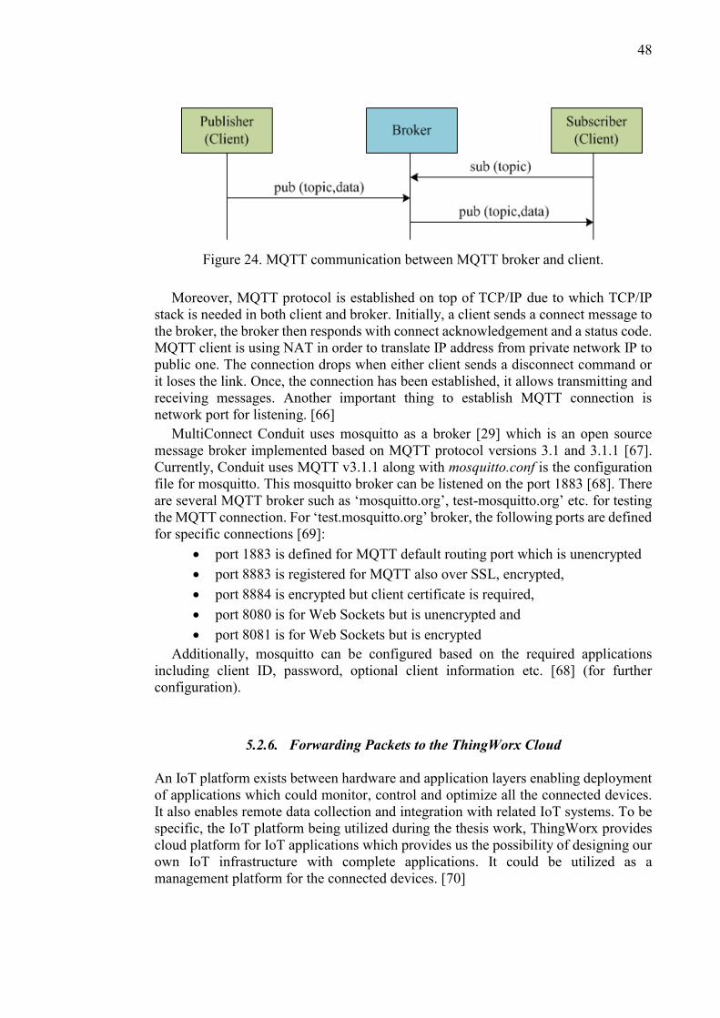
48
Figure 24. MQTT communication between MQTT broker and client.
Moreover, MQTT protocol is established on top of TCP/IP due to which TCP/IP
stack is needed in both client and broker. Initially, a client sends a connect message to
the broker, the broker then responds with connect acknowledgement and a status code.
MQTT client is using NAT in order to translate IP address from private network IP to
public one. The connection drops when either client sends a disconnect command or
it loses the link. Once, the connection has been established, it allows transmitting and
receiving messages. Another important thing to establish MQTT connection is
network port for listening. [66]
MultiConnect Conduit uses mosquitto as a broker [29] which is an open source
message broker implemented based on MQTT protocol versions 3.1 and 3.1.1 [67].
Currently, Conduit uses MQTT v3.1.1 along with mosquitto.conf is the configuration
file for mosquitto. This mosquitto broker can be listened on the port 1883 [68]. There
are several MQTT broker such as ‘mosquitto.org’, test-mosquitto.org’ etc. for testing
the MQTT connection. For ‘test.mosquitto.org’ broker, the following ports are defined
for specific connections [69]:
port 1883 is defined for MQTT default routing port which is unencrypted
port 8883 is registered for MQTT also over SSL, encrypted,
port 8884 is encrypted but client certificate is required,
port 8080 is for Web Sockets but is unencrypted and
port 8081 is for Web Sockets but is encrypted
Additionally, mosquitto can be configured based on the required applications
including client ID, password, optional client information etc. [68] (for further
configuration).
5.2.6. Forwarding Packets to the ThingWorx Cloud
An IoT platform exists between hardware and application layers enabling deployment
of applications which could monitor, control and optimize all the connected devices.
It also enables remote data collection and integration with related IoT systems. To be
specific, the IoT platform being utilized during the thesis work, ThingWorx provides
cloud platform for IoT applications which provides us the possibility of designing our
own IoT infrastructure with complete applications. It could be utilized as a
management platform for the connected devices. [70]

49
In order to send LoRa packets from the MultiConnect Conduit to the ThingWorx
cloud using the 5GTN, different configurations are being followed which we will
discuss here in details. The Node-red needs to be configured beforehand which
involves connection of the ‘LoRa’ (from the input) and MQTT blocks as shown in
Figure 25. The MQTT needs to be configured by specifying the server name, port
number, topic, QoS and name of the Property. This will send the payload of the LoRa
packet by default but if additional information (device EUI, channel information,
signal strength, etc.) is required then relevant function blocks needs to be added.
Figure 25. Node-red configuration for forwarding packets to the ThingWorx.
Initially, having imported the MQTT extension to the ThingWorx platform, a
‘Thing’ is created by using the MQTT template. Then, a ‘Property’ is created keeping
in view the property assigned in the Node-red configuration. The next step being
followed was the addition of ‘topic’ and ‘Property’ in the Configuration menu in
relevance to the Node-red’s MQTT configuration. It is critical to note that the property
and topic should be same as we created earlier in the Node-red. To ensure the
connectivity after saving all the changes, in the property menu, the connection if
established would give a ‘true’ value for ‘isconnected’. Figure 26 shows the
configuration in the ThingWorx for receiving LoRa packet.

50
Figure 26. ThingWorx configuration for receiving a LoRa packet using WAN.
Once the connection is active, an end-device starts to transmit the packets to the
gateway for which we use mosquitto_sub –t lora/+/+ -v script. The gateway having
an LTE connection forwards the data using Node-red app in the Conduit to the
ThingWorx. The data is then received on the ThingWorx with the same format as is
received on the Conduit. If multiple end-devices are used then the data is distinguished
by their respective ‘device EUI’ on the ThingWorx and the MultiConnect Conduit
itself. Figure 27 shows the connection between MQTT client and ‘mosquitto.org’
broker in the ThingWorx and display the received LoRa packet from Conduit to
ThingWorx.

51
Figure 27. Connection established using the MQTT protocol and an example
received packet.
Similarly, the downlink communication from ThingWorx to MultiConnect Conduit
is possible to establish by using the same mosquitto broker as used for uplink. To
implement such configuration, another ‘property’ named ‘downlink’ is created on
different ‘topic’ and this property is then added in the configuration under same
‘Thing’. It is important to note that, when ‘Property’ is added in the ThingWorx, the
property needs to subscribe to display the message on ThingWorx. Similarly, the
property for downlink needs to publish while transmitting message from ThingWorx
to Conduit. The configuration is shown in Figure 28.
Figure 28. ‘downlink’ Property creation for downlink communication.
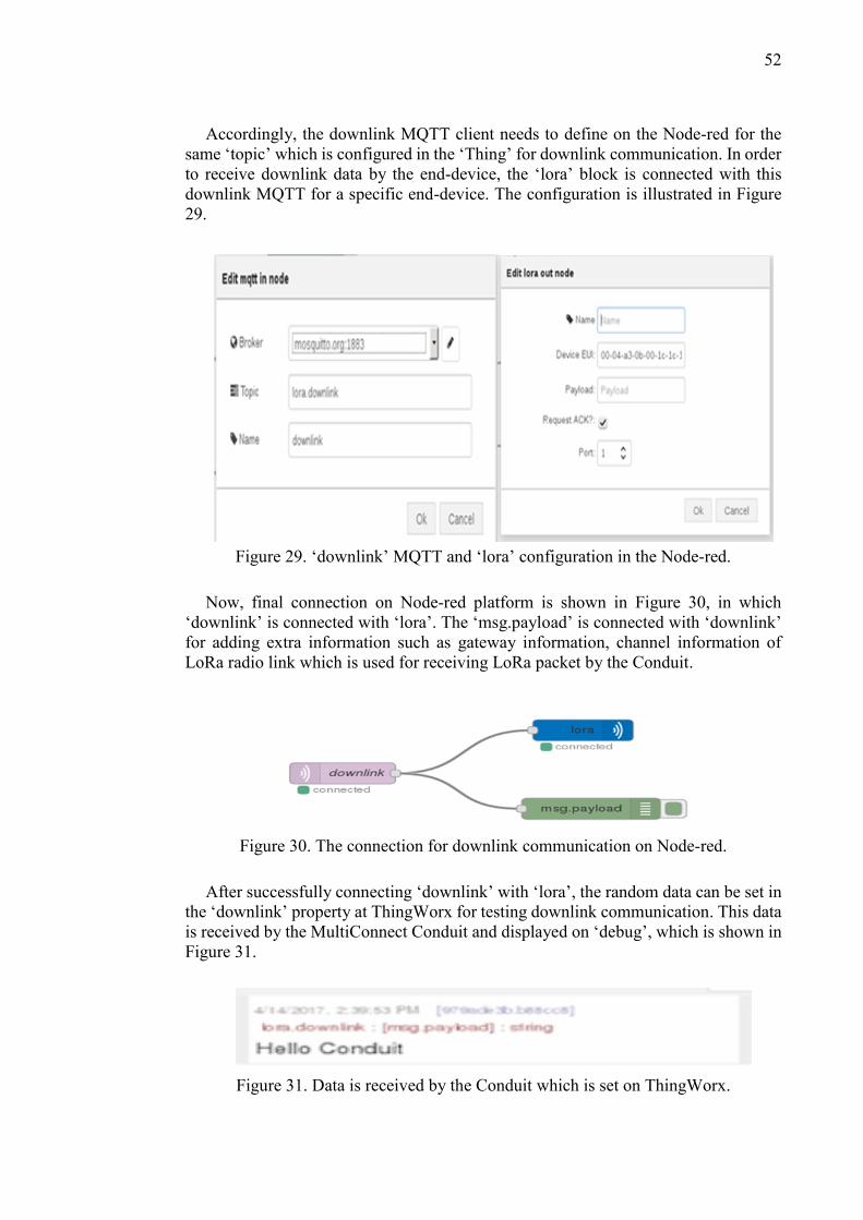
52
Accordingly, the downlink MQTT client needs to define on the Node-red for the
same ‘topic’ which is configured in the ‘Thing’ for downlink communication. In order
to receive downlink data by the end-device, the ‘lora’ block is connected with this
downlink MQTT for a specific end-device. The configuration is illustrated in Figure
29.
Figure 29. ‘downlink’ MQTT and ‘lora’ configuration in the Node-red.
Now, final connection on Node-red platform is shown in Figure 30, in which
‘downlink’ is connected with ‘lora’. The ‘msg.payload’ is connected with ‘downlink’
for adding extra information such as gateway information, channel information of
LoRa radio link which is used for receiving LoRa packet by the Conduit.
Figure 30. The connection for downlink communication on Node-red.
After successfully connecting ‘downlink’ with ‘lora’, the random data can be set in
the ‘downlink’ property at ThingWorx for testing downlink communication. This data
is received by the MultiConnect Conduit and displayed on ‘debug’, which is shown in
Figure 31.
Figure 31. Data is received by the Conduit which is set on ThingWorx.

53
5.3. Monitoring LoRa Packet
Having integrated MultiConnect Conduit to be permanently part of the 5GTN as an
IoT infrastructure with thousands of end-devices, the ThingWorx provides constant
monitoring of the data from those end-devices. Though LoRaWAN is proved to be an
efficient IoT enabler out of the LPWAN space yet the performance monitoring is
requisite to ensure the capability of such an integration. After connecting Conduit with
the core of the 5GTN, the LoRa packets can be monitored within the network by using
Wireshark [71]. Therefore, LoRa packets from the end-devices all the way to the
ThingWorx can be analysed in both directions i.e. uplink and downlink.
5.3.1. Wireshark Traces for MQTT packets
By using 5GTN core for cellular connectivity, LoRa packets can be transmitted
successfully from Conduit to ThingWorx cloud. The Conduit transmits all packets
being received from end-devices to the ThingWorx platform which is then stored in a
property, i.e., ‘LoRaWAN’ under the Thing named as ‘MQTT_test’. The ‘EUI’ of end-
device is ’00-04-a3-0b-00.1c-1c-18’. Figure 32 shows the successful connection
between Conduit and ThingWorx and uplink and downlink messages in the
ThingWorx. In order to monitor network performance while carrying LoRa packets, a
Wireshark trace is taken at the Pico cell (or eNodeB). We are using 5GTN’s network
to transmit the LoRa packets from the end-devices to the ThingWorx. Wireshark trace
is captured merely while actual LoRa packets is transmitted by using 5GTN network.
Figure 32. Integrating MultiConnect Conduit with ThingWorx successfully.
From Wireshark trace at Pico cell, it is observed that packet has been published
from source IP (10.92.148.108) to destination IP (85.119.83.194) as shown in Figure

54
33. The source IP which is the local IP of Conduit will be received from the user IP
pool of 5GTN and destination IP is the server IP (server based on MQTT) which is
used to transmit LoRa packet to ThingWorx. After that, this packet is published on
‘property’ under ‘Thing’. We can create our own server by using ‘mosquitto.conf’ file
with own IP/name.
Figure 33. Wireshark log file at Pico cell for uplink.
It is possible to trace the downlink data from ThingWorx to MultiConnect Conduit
at the Pico cell as the downlink communication has been done through the same route.
In the downlink, the message is published from mosquitto broker (85.119.83.194) to
the Conduit (10.92.148.108) as a ‘Publish Message’.
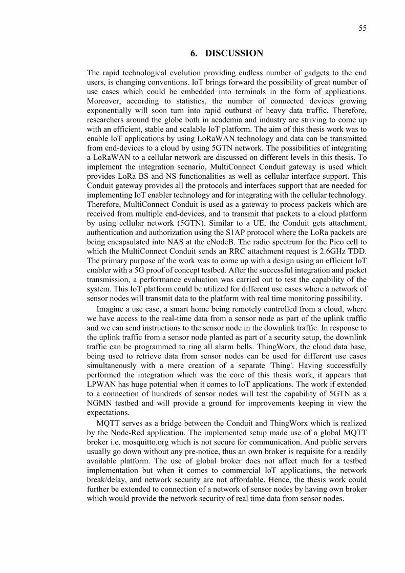
55
6. DISCUSSION
The rapid technological evolution providing endless number of gadgets to the end
users, is changing conventions. IoT brings forward the possibility of great number of
use cases which could be embedded into terminals in the form of applications.
Moreover, according to statistics, the number of connected devices growing
exponentially will soon turn into rapid outburst of heavy data traffic. Therefore,
researchers around the globe both in academia and industry are striving to come up
with an efficient, stable and scalable IoT platform. The aim of this thesis work was to
enable IoT applications by using LoRaWAN technology and data can be transmitted
from end-devices to a cloud by using 5GTN network. The possibilities of integrating
a LoRaWAN to a cellular network are discussed on different levels in this thesis. To
implement the integration scenario, MultiConnect Conduit gateway is used which
provides LoRa BS and NS functionalities as well as cellular interface support. This
Conduit gateway provides all the protocols and interfaces support that are needed for
implementing IoT enabler technology and for integrating with the cellular technology.
Therefore, MultiConnect Conduit is used as a gateway to process packets which are
received from multiple end-devices, and to transmit that packets to a cloud platform
by using cellular network (5GTN). Similar to a UE, the Conduit gets attachment,
authentication and authorization using the S1AP protocol where the LoRa packets are
being encapsulated into NAS at the eNodeB. The radio spectrum for the Pico cell to
which the MultiConnect Conduit sends an RRC attachment request is 2.6GHz TDD.
The primary purpose of the work was to come up with a design using an efficient IoT
enabler with a 5G proof of concept testbed. After the successful integration and packet
transmission, a performance evaluation was carried out to test the capability of the
system. This IoT platform could be utilized for different use cases where a network of
sensor nodes will transmit data to the platform with real time monitoring possibility.
Imagine a use case, a smart home being remotely controlled from a cloud, where
we have access to the real-time data from a sensor node as part of the uplink traffic
and we can send instructions to the sensor node in the downlink traffic. In response to
the uplink traffic from a sensor node planted as part of a security setup, the downlink
traffic can be programmed to ring all alarm bells. ThingWorx, the cloud data base,
being used to retrieve data from sensor nodes can be used for different use cases
simultaneously with a mere creation of a separate 'Thing'. Having successfully
performed the integration which was the core of this thesis work, it appears that
LPWAN has huge potential when it comes to IoT applications. The work if extended
to a connection of hundreds of sensor nodes will test the capability of 5GTN as a
NGMN testbed and will provide a ground for improvements keeping in view the
expectations.
MQTT serves as a bridge between the Conduit and ThingWorx which is realized
by the Node-Red application. The implemented setup made use of a global MQTT
broker i.e. mosquitto.org which is not secure for communication. And public servers
usually go down without any pre-notice, thus an own broker is requisite for a readily
available platform. The use of global broker does not affect much for a testbed
implementation but when it comes to commercial IoT applications, the network
break/delay, and network security are not affordable. Hence, the thesis work could
further be extended to connection of a network of sensor nodes by having own broker
which would provide the network security of real time data from sensor nodes.

56
5GTN as a testbed is open to researchers to come up with innovative use cases. The
idea of integrating LoRaWAN as an IoT enabler with a cellular network was unclear
initially. Keeping in view previous LoRa BS, it was assumed that the connection would
more likely be a non-3GPP connection directly to the ePDG of the EPC. The
MultiConnect Conduit using PPP to establish an S1 connectivity like an LTE UE,
clarifies the possibility of such a connection. Having connected to 5GTN, the Conduit
is capable to handle a network of end-devices constantly forwarding real time data
packets to a centralized cloud data base. It is a practical demonstration for an IoT
gateway integrated within cellular networks which could make lots of use cases,
practical. ThingWorx being used as Platform as a Service (PaaS) which does not
ensure the availability (when needed) of all the data from sensor nodes, as the data gets
overwritten every time when a new data is being received. When a large number of
sensor nodes will be connected in future, the real-time data needs a data storage
backend. The thesis work can be extended to creation of an own ThingWorx data base
in University IT servers instead of using it as PaaS. In order to realize it in practice,
Postgresql [74] and apache Tomcat [75] should be installed which would serve the
purpose of a data base [76]. The data traffic from sensor nodes can then be routed to
the data base using 5GTN data path routes, which could then be retrieved when
required.

57
7. SUMMARY
LPWAN is a promising technology for future IoT applications as it is an IoT enabler
technology. LoRaWAN due to its low bandwidth has proven to be an efficient IoT
enabler in NGMN. The current mobile network is at the verge of a major evolution to
be capable of 5G expectations/requirements in which IoT platform would be a primary
part, enabling various use cases. In order to build up an IoT infrastructure,
MultiConnect Conduit as a LoRa gateway, is integrated with a 5G proof of concept
testbed i.e., 5GTN to test the feasibility of IoT applications. The thesis work comprised
of evaluating several possibilities by studying different techniques individually.
Though the integration formed out to be not possible the way those techniques were
studied yet the evaluation lead us to a different way of integration. The point-to-point
protocol is used for a WAN connection in which the connection is made between
Conduit and Pico cell over ppp0 interface which provides Internet from the 5GTN.
After receiving data transmitted from end-device on the MultiConnect Conduit, it is
forwarded to the ThingWorx platform using Node-red application. Similarly, the
downlink packet is received by the end-device from the ThingWorx through the
Conduit. Having connected with 5GTN, the MultiConnect Conduit is capable to
transmit and received data to and from the ThingWorx by using MQTT protocol.
Therefore, it could be possible to enable IoT applications by using such integrated IoT
enabler network platform by collecting real data from sensor node.
MultiConnect Conduit provides a user-friendly Node-red application platform
where connection is made easily based on applications without programmable coding
(like C, C++, java etc.). Instead, Conduit allows to install LoRa mCard to support
LoRaWAN and support SIM card to enable cellular connection. It also supports
MQTT protocol on top of TCP/IP to enable communication between MQTT client and
broker. A client is capable to communicate with other client using same ‘topic’_
through the MQTT broker. Having successfully integrated MultiConnect Conduit with
the 5GTN, the deployment of IoT applications is much easier practically due to having
support of multiple protocols in a single Conduit platform.

58
8. REFERENCES
[1] Bardyn J.-P., Melly T. Seller O. & Sornin N. (2016) IoT: The era of LPWAN is
starting now. In: IEEE European Solid-State Circuits Conference, Sept. 12-15,
Lausanne, Switzerland, pp. 25-30.
[2] NGMN. (Read 25.03.2017) A Deliverable by the NGMN Alliance, NGMN 5G
White paper. URL: https://www.ngmn.org/uploads/media/NGMN_5G _White_
Paper_V1_0.pdf.
[3] Piri E., Ruuska P., Kanstren T., Mäkelä J., Korva J., Hekkala A., Pouttu A.,
Liinamaa O., Latva-aho M., Vierimaa K. & Valasma H. (2016) 5GTN: A test
network for 5G application development and testing. In: European Conference
on Networks and Communications (EuCNC), June 27-30, Athens, Greece, pp.
313-318.
[4] Islam M. S., Jessy T., Hassan M. S., Mondal K. & Rahman T. (2016) Suitable
beamforming technique for 5G wireless communications. In: International
Conference on Computing, Communication and Automation (ICCCA), April
29-30, Noida, India, pp. 1554-1559.
[5] Zhang K., Mao Y., Leng S., Zhao Q., Li L., Peng X., Pan L., Maharjan S. &
Zhang Y. (2016) Energy-Efficient Offloading for Mobile Edge Computing in 5G
Heterogeneous Networks. Green Communications and Networking for 5G
Wireless, vol. 4, pp. 5896-5907.
[6] ETSI. (Read 17.12.2016) ETSI GS NFV 002 V1.1.1, Network Functions
Virtualization (NFV); Architectural Framework. URL: http://www.etsi.org/
deliver/etsi_gs/nfv/001_099/002/01.01.01_60/gs_nfv002v010101p.pdf.
[7] ETSI. (Read 23.01.2017) Network Functions Virtualization-Introductory White
Paper. URL: https://portal.etsi.org/NFV/NFV_White_Paper.pdf.
[8] Rappaport T. S., Sun S., Mayzus R., Zhao H., Azar Y., Wang K., Wong G. N.,
Schulz J. K., Samimi M., & Gutierrez F. (2013) Millimeter Wave Mobile
Communications for 5G Cellular: It Will Work!. IEEE Access, vol. 1, pp. 335-
349.
[9] Ali A., Shah G. A. & Arshad J. (2016) Energy efficient techniques for M2M
communication: A survey. Journal of Network and Computer Applications, Vol.
68, pp. 42-55.
[10] Song Q., Nuaymi L. & Lagrange X. (2016) Survey of radio resource
management issues and proposals for energy-efficient cellular networks that will
cover billions of machines. EURASIP Journal on Wireless Communications and
Networking 140, pp. 1-20.
[11] 3GPPTM. (Read 04.05.2017) 3GPP TR 23.888 V11.0.0, 3rd Generation
Partnership Project; Technical Specification Group Services and System
59
Aspects; System improvements for Machine-Type Communications (MTC).
URL: http://www.qtc.jp/3GPP/Specs/23888-b00.pdf.
[12] Cisco. (Read 06.05.2017) Cisco Visual Networking Index: Global Mobile Data
Traffic Forecast Update, 2015-2020. URL: http://www.cisco.com/c/dam/m/
en_in/innovation/enterprise/assets/mobile-white-paper-c11-520862.pdf.
[13] Peter R. Egli. (Read 14.01.2017) LPWAN: Low Power Wide Area Network.
URL: https://www.scribd.com/document/258682723.
[14] ETSI. (Read 04.05.2017) ETSI TR 122 934 V6.2.0, Universal Mobile
Telecommunications System (UMTS); Feasibility study on 3GPP system to
Wireless Local Area Network (WLAN) interworking. URL:
http://www.etsi.org/deliver/etsi_tr/122900_122999/122934/06.02.00_60/tr_122
934v060200p.pdf.
[15] 3GPPTM. (Read 04.05.2017) The Mobile Broadband Standard. URL:
http://www.3gpp.org/technologies/keywords-acronyms/98-lte.
[16] Margelis G., Piechocki R., Kaleshi D. & Thomas P. (2015) Low Throughput
Networks for the IoT: Lessons learned from industrial implementations. In:
IEEE 2nd World Forum on Internet of Things (WF-IoT), Dec. 14-16, Milan,
Italy, pp. 181-186.
[17] HUAWEI. (Read 04.05.2017) NB-IOT-Enabling New Business Opportunities.
URL: http://www.huawei.com/minisite/iot/img/nb_iot_whitepaper_en.pdf.
[18] Moyer B. (Read 04.05.2017) Low Power, Wide Area: A Survey of Longer-
Range IoT Wireless Protocols. URL: http://www.eejournal.com/archives/
articles/20150907- lpwa.
[19] 5G Berlin. (Read 05.05.2017) Providing 5G-Access, 5G-Core & Xhaul
Technologies in combination with SDN/NFV/MEC Service Platforms at a single
location NOW. URL: http://www.5g-berlin.org.
[20] Martinez R., Munoz R., Requena M., Sorribes J., Comellas J. & Junyent G.
(2006) ADRENALINE testbed: architecture and implementation of GMPLS-
based network resource manager and routing controller. In: 2nd International
Conference on Testbeds and Research Infrastructures for the Development of
Networks and Communities (TRIDENTCOM), March 1-3, Barcelona, Spain,
pp. 74-83.
[21] University of Surrey. (Read 06.05.2017) 5G Innovation Centre. URL:
https://www.surrey.ac.uk/5gic.
[22] 5GTN. (Read 20.03.2017) 5GTN – 5G Test Network. URL: http://5gtn.fi.
[23] Latva-aho M., Pouttu A., Hekkala A., Harjula I. & Mäkelä J. (2015) Small Cell
Based 5G Test Network (5GTN). In: Twelfth International Symposium on
Wireless Communication Systems (ISWCS), Aug. 25-28, Brussels, Belgium, pp.
231-235.

60
[24] Raza U., Kulkarni P. & Sooriyabandara M. (2017) Low Power Wide Area
Networks: An Overview. IEEE Communications Surveys & Tutorials, pp. 1-19.
[25] ETSI. (Read 24.04.2017) ETSI TS 118 110 V1.1.0, oneM2M; MQTT Protocol
Binding (oneM2M TS-0010 version 1.5.1 Release 1). URL:
http://www.etsi.org/deliver/etsi_ts/118100_118199/118110/01.01.00_60/ts_11
8110v010100p.pdf.
[26] ETSI. (Read 04.05.2017) ETSI TS 118 108 V1.0.0, CoAP Protocol Binding.
URL: http://www.etsi.org/deliver/etsi_ts/118100_118199/118108/01.00.00_60
/ts_118108v010000p.pdf.
[27] ETSI. (Read 5.5.2017) ETSI. URL: http://www.etsi.org.
[28] Sigfox. (Read 20.03.2017) Sigfox, the world’s leading Internet of things (IoT)
connectivity service. URL: https://www.sigfox.com/en.
[29] Telensa. (Read 04.05.2017) Telensa PLANet: wireless lighting control
optimised for Smart Cities. URL: http://www.telensa.com.
[30] Semtech. (Read 04.05.2017) Semtech. URL: http://www.semtech.com.
[31] Nokia. (Read 20.03.2017) LTE-M—optimizing LTE for the Internet of Things,
White paper. URL: https://novotech.com/docs/default-source/default-
document-library/lte-m-optimizing-lte-for-the-internet-of-things.pdf?sfvrsn=0.
[32] Ingenu. (Read 04.05.2017) RPMA Technology. URL: https://www.ingenu.com/
technology/rpma.
[33] Phua V., Datta A. & Cardell-Oliver R. (2006) WLC12-5: A TDMA-Based MAC
Protocol for Industrial Wireless Sensor Network Applications using Link State
Dependent Scheduling. In: Global Telecommunications Conference,
GLOBECOM '06, IEEE, Nov. 27-Dec. 1, San Francisco, CA, USA, pp. 1-6.
[34] Chirdchoo N., Soh W. S. & Chua K. C. (2007) Aloha-Based MAC Protocols
with Collision Avoidance for Underwater Acoustic Networks. In: IEEE
INFOCOM 2007 - 26th IEEE International Conference on Computer
Communications, May 6-12, Barcelona, Spain, pp. 2271-2275.
[35] Weightless. (Read 04.05.2017) Weightless-N open standard IoT networks
deploy in Europe. URL: http://www.weightless.org/news/weightlessn-open-
standard-iot-networks-deploy-in-europe.
[36] Real Wireless. (Read 06.05.2017) A Comparison of UNB and Spread Spectrum
Wireless technologies as used in LPWA M2M Applications. URL:
https://www.thethingsnetwork.org/forum/uploads/default/original/1X/3b1c1ae4
a925e9aa897110ccde10ec61f3106b87.pdf.
[37] Semtech. (Read 20.11.2016) AN1200.22, LoRa™ Modulation Basics. URL:
http://www.semtech.com/images/datasheet/an1200.22.pdf.

61
[38] Petäjäjärvi J., Mikhaylov K., Pettissalo M., Janhunen J. & Iinatti J. (2017)
Performance of a low-power wide-area network based on LoRa technology:
Doppler robustness, scalability, and coverage. International Journal of
Distributed Sensor Networks, vol. 13, pp. 1-16.
[39] Semtech. (Read 17.11.2016) LoRaWAN Specification v1.0. Jan. 2015. URL:
https://www.lora-alliance.org/portals/0/specs/LoRaWAN%20Specification%20
1R0.pdf.
[40] LoRa Alliance™. (Read 20.12.2016) LoRaWAN™ Security, Full End-To-End
Encryption for IoT Application Providers. URL: https://www.lora-alliance.org/
portals/0/documents/whitepapers/LoRaWAN_Security-Whitepaper_V6_Digita
l.pdf.
[41] Semtech. (Read 09.01.2017) Semtech. URL: http://www.semtech.com/wireless-
rf/lora/LoRa-FAQs.pdf.
[42] Petäjäjärvi J., Mikhaylov K., Roivainen A., Hänninen T. & Pettissalo M. (2015)
On the coverage of LPWANs: range evaluation and channel attenuation model
for LoRa technology. In: 14th International Conference on ITS
Telecommunications (ITST), Dec. 2-4, Copenhagen, Denmark, pp. 55-59.
[43] So J., Kim D., Kim H., Lee H. & Park S. (2016) LoRaCloud: LoRa platform on
OpenStack. In: IEEE NetSoft Conference and Workshops (NetSoft), July 6-10,
Seoul, South Korea, pp. 431-434.
[44] LoRa Alliance™. (Read 20.11.2016) LoRa Alliance™ Technology. URL:
https://www.lora-alliance.org/What-Is-LoRa/Technology.
[45] Semtech. (Read 25.12.2017) LoRa SX1272/73, Wireless & Sensing Products.
URL: http://www.semtech.com/images/datasheet/sx1272.pdf.
[46] 3GPP. (Read 03.05.2017) The Evolved Packet Core. URL:
http://www.3gpp.org/technologies/keywords-acronyms/100-the-evolved-packet
-core.
[47] ETSI. (Read 07.05.2017) ETSI TS 123 228 V11.10.0, Digital cellular
telecommunications system (Phase 2+); Universal Mobile Telecommunications
System (UMTS); LTE; IP Multimedia Subsystem (IMS); Stage 2 (3GPP TS
23.228 version 11.10.0 Release 11). URL: http://www.etsi.org/deliver/etsi_ts/
123200_123299/123228/11.10.00_60/ts_123228v111000p.pdf.
[48] Core Network Dynamics. (Read 13.12.2016) OpenEPC won the Next-Gen
Deployment for Wireless Networks. URL: http://www.corenetdynamics.com.
[49] Fraunhofer FOKUS. (Read 13.12.2016) OpenEPC: Open Evolved Packet Core
Platform. URL: http://www.av.tu-berlin.de/uploads/media/Datenblatt_Open
EPC_2009_10_web.pdf.
[50] Ubuntu. (Read 05.05.2017) Ubuntu. URL: https://www.ubuntu.com.

62
[51] Vmware (Read 05.05.2017) vSphere ESXi Hypervisor Features. URL:
http://www.vmware.com/products/esxi-and-esx.html.
[52] Corici M., Magedanz T., Vingarzan D. & Weik P. (2010) Prototyping mobile
broadband applications with the open Evolved Packet Core. In: 14th
International Conference on Intelligence in Next Generation Networks, Oct. 11-
14, Berlin, Germany, pp. 1-5.
[53] ETSI. (Read 05.05.2017) ETSI TS 136 104 V9.4.0, LTE; Evolved Universal
Terrestrial Radio Access (E-UTRA); Base Station (BS) radio transmission and
reception (3GPP TS 36.104 version 9.4.0 Release 9). URL:
http://www.etsi.org/deliver/etsi_ts/136100_136199/136104/09.04.00_60/ts_13
6104v090400p.pdf.
[54] ETSI. (Read 07.05.2017) Digital cellular telecommunications system (Phase
2+); Universal Mobile Telecommunications System (UMTS); LTE; Network
architecture (3GPP TS 23.002 version 12.5.0 Release 12). URL:
http://www.etsi.org/deliver/etsi_ts/123000_123099/123002/12.05.00_60/ts_12
3002v120500p.pdf.
[55] Srinivasa Rao V. & Gajula R. (Read 21.01.2017) Protocol Signaling Procedures
in LTE. URL: http://go.ccpu.com/rs/CCPU/images/wp-signal-procedures-lte.
pdf?mkt_tok=3RkMMJWWfF9wsRonuaXBZKXonjHpfsX57uUqUaag38431
UFwdcjKPmjr1YIFRMZ0dvycMRAVFZl5nS97KtU%3D.
[56] ETSI. (Read 05.03.2017) ETSI TS 136 410 V12.1.0, LTE; Evolved Universal
Terrestrial Radio Access Network (E-UTRAN); S1 general aspects and
principles (3GPP TS 36.410 version 12.1.0 Release 12). URL:
http://www.etsi.org/deliver/etsi_ts/136400_136499/136410/12.01.00_60/ts_13
6410v120100p.pdf.
[57] Core Network Dynamic. (Read 27.01.2017) OpenEPC++. URL:
https://sites.google.com/a/corenetdynamics.com/home/open-epc.
[58] Taneja M. (2016) LTE-LPWA networks for IoT applications. In: International
Conference on Information and Communication Technology Convergence
(ICTC),Oct. 19-21, Jeju, South Korea, pp. 396-399.
[59] 3GPPTM. (Read 11.03.2017) 3GPP TS 24.301 V8.1.0 (2009-03). URL:
http://www.arib.or.jp/IMT-2000/V730Jul09/5_Appendix/Rel8/24/24301-
810.pdf.
[60] Multitech. (Read 05.03.2017) Multitech Developer Resources. URL:
http://www.multitech.net/developer.
[61] Multitech. (Read 06.03.2017) MultiConnect. URL: http://www.multitech.com/
documents/publications/manuals/s000655.pdf
[62] Node-RED. (13.03.2017) Node-RED: Flow-based Programming for the Internet
of Things. URL: http://nodered.org.

63
[63] Juniper. (Read 26.03.2017) Understanding Point-to-Point Protocol. URL:
https://www.juniper.net/documentation/en_US/junos12.1x47/topics/concept/int
erface-security-encapsulation-point-to-point-protocol-understanding.html.
[64] Mackerras P. (Read 16.03.2017) Point-to-Point Protocol Daemon. URL:
https://ppp.samba.org/pppd.html.
[65] MQTT. (Read 17.03.2017) MQTT.org. URL: http://mqtt.org/.
[66] HiveMQ. (Read 16.03.2017) MQTT Essentials Part 3: Client, Broker and
Connection Establishment. URL: http://www.hivemq.com/blog/mqtt-essentials-
part-3-client-broker-connection-establishment.
[67] Eclipse. (Read 17.03.2017) Mosquitto: An Open Source MQTT v3.1/v3.1.1
Broker. URL: https://mosquitto.org.
[68] Light R. (Read 17.03.2017) Mosquitto.conf. URL: https://mosquitto.org/man/
mosquitto-conf-5.html.
[69] Eclipse. (Read 17.03.2017) Mosquitto. URL: http://test.mosquitto.org.
[70] ThingWorx. (Read 18.03.2017) The ThingWorx IoT Technology Platform.
URL: https://www.thingworx.com/platforms.
[71] Wireshark. (Read 07.05.2017) Wireshark. URL: https://www.wireshark.org.
[72] ETSI. (Read 08.05.2017) ETSI TS 123 401 V11.3.0, LTE; General Packet Radio
Service (GPRS) enhancements for Evolved Universal Terrestrial Radio Access
Network (E-UTRAN) access (3GPP TS 23.401 version 11.3.0 Release 11).
URL: http://www.etsi.org/deliver/etsi_ts/123400_123499/123401/11.03.00_60/
ts_123401v110300p.pdf.
[73] Cisco. (Read 07.05.2017) Configuring Internet Key Exchange Security Protocol.
URL: http://www.cisco.com/c/en/us/td/docs/ios/12_2/security/configuration/gu
ide/fsecur_c/scfike.pdf.
[74] Postgresql. (Read 11.05.2015) Postgresql. URL: https://www.postgresql.org.
[75] Apache Tomcat. (Read 11.05.2017) Apache Tomcat. URL:
http://tomcat.apache.org.
[76] ThingWorx. (Read 20.04.2017) ThingWorx. URL: http://support.ptc.com/
WCMS/files/170230/en/Installing_ThingWorx_7.1_1.pdf.
[77] OpenStack. (Read 06.04.2017) OpenStack URL: https://www.openstack.org/
software.