Embed Size (px)
Citation preview
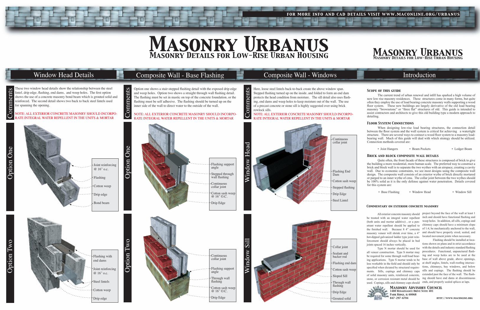
Scope of this guide The current trend of urban renewal and inll has sparked a high volume of new low rise masonry residences. These structures come in many forms, but quite often they employ the use of load bearing concrete masonry walls supporting a wood oor system. These new buildings are largely derivative of the old load bearing masonry “brownstone” or “three at” structures of old. This guide is intended to assist contractors and architects to give this old building type a modern approach to detailing.
Floor System Connections When designing low-rise load bearing structures, the connection detail between the oor system and the wall system is critical for achieving a watertight structure. There are several ways to connect a wood oor system to a masonry load-bearing wall. Much of this guide will deal with which strategy should be utilized. Connection methods covered are:
• Joist Hangers • Beam Pockets • Ledger Beam
Brick and block composite wall details Quite often, the front facade of these structures is composed of brick to give the building a more residential, more human scale. The preferred way to construct a brick and block wall is to separate the two wythes with an airspace, creating a cavity wall. Due to economic constraints, we see most designs using the composite wall design. The composite wall consists of an exterior wythe of brick directly mortared or parged to an inner wythe of cmu. The collar joint between the two wythes should be 100% solid as it is the only defense against water penetration. Details covered for this system are: • Base Flashing • Window Head • Window Sill
All exterior concrete masonry should be treated with an integral water repellent (both units and mortar additive) , or a pen-etrant water repellent should be applied to the nished wall. Because 8 4” concrete masonry veneer will shrink over time, a 4” hot-dipped galvanized ladder type joint rein-forcement should always be placed in bed joints spaced 16 inches vertically. Type N mortar should be used for all veneer construction. Type S mortar may be required for some through wall/load bear-ing applications. Type S mortar tends to be less workable in the eld and should only be specied when dictated by structural require-ments. Sills, copings and chimney caps of solid masonry units, reinforced concrete, stone, or corrosion resistant metal should be used. Copings, sills and chimney caps should
project beyond the face of the wall at least 1 inch and should have functional ashing and weep holes. In addition, all sills, copings and chimney caps should have a minimum slope of 1:4, be mechanically anchored to the wall, and should have properly sized, sealed, and located movement joints when necessary. Flashing should be installed at loca-tions shown on plans and in strict accordance with the details and industry standard ashing procedures. Functional, unpunctured ash-ing and weep holes are to be used at the base of wall above grade, above openings, at shelf angles, lintels, wall-roong intersec-tions, chimneys, bay windows, and below sills and copings. The ashing should be extended past the face of the wall. The ash-ing should have end dams at discontinuous ends, and properly sealed splices at laps.
Commentary on exterior concrete masonry
Masonry Advisory Council1480 Renaissance Drive Suite 401Park Ridge, il 60068847-297-6704 http://www.maconline.org
Composite Wall - Windows
Win
dow
Hea
dW
indo
w S
illC
omm
ents Here, loose steel lintels back-to-back create the above window span.
Stepped flashing turned up on the inside, and folded to form an end dam protects the head condition from moisture. The sill detail also uses flash-ing, end dams and weep holes to keep moisture out of the wall. The use of a precast concrete or stone sill is highly suggested over using brick rowlock sills.NOTE: ALL EXTERIOR CONCRETE MASONRY SHOULD INCORPO-RATE INTEGRAL WATER REPELLENT IN THE UNITS & MORTAR
Continuouscollar joint
Flashing End Dam
Cotton sash weep
Stepped flashing
Drip Edge
Steel Lintel
Collar joint
Sealant and backer rod
Flashing end dam
Cotton sash weep
Sloped Sill
Through wall flashing
Drip Edge
Grouted solid
Masonry UrbanusMasonry Details for Low-Rise Urban Housing
for more info and cad details visit www.maconline.org/urbanus
Composite Wall - Base Flashing
Opt
ion
One
Opt
ion
Two
Com
men
ts Option one shows a stair-stepped flashing detail with the exposed drip edge and weep holes. Option two shows a straight through wall flashing detail. The flashing must be set in mastic on top of the concrete foundation, or the flashing must be self adhesive. The flashing should be turned up on the inner side of the wall to direct water to the outside of the wall.
NOTE: ALL EXTERIOR CONCRETE MASONRY SHOULD INCORPO-RATE INTEGRAL WATER REPELLENT IN THE UNITS & MORTAR
Flashing support angle
Stepped through wall flashing
Continuouscollar joint
Cotton sash weep @ 16” O.C.
Drip Edge
Continuouscollar joint
Flashing supportangle
Through wall flashing
Cotton sash weep @ 16” O.C.
Drip Edge
Window Head Details
Opt
ion
One
Opt
ion
Two
Com
men
ts These two window head details show the relationship between the steel lintel, drip edge, flashing, end dams, and weep holes. The first option shows the use of a concrete masonry bond beam which is grouted solid and reinforced. The second detail shows two back to back steel lintels used for spanning the opening.
NOTE: ALL EXTERIOR CONCRETE MASONRY SHOULD INCORPO-RATE INTEGRAL WATER REPELLENT IN THE UNITS & MORTAR
Joint reinforcing @ 16” o.c.
Flashing
Cotton weep
Drip edge
Bond beam
Flashing withend dams
Joint reinforcing @ 16” o.c.
Steel lintels
Cotton weep
Drip edge
Introduction
Masonry UrbanusMasonry Details for Low-Rise Urban Housing
Masonry UrbanusMasonry Details for Low-Rise Urban Housing
for more info and cad details visit www.maconline.org/urbanus
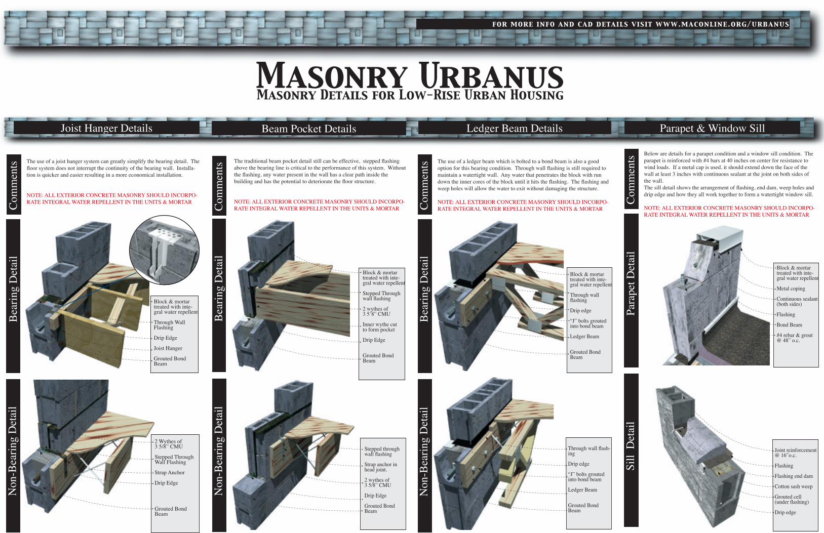
Beam Pocket Details
Bea
ring
Det
ail
Non
-Bea
ring
Det
ail
Com
men
ts The traditional beam pocket detail still can be effective, stepped flashing above the bearing line is critical to the performance of this system. Without the flashing, any water present in the wall has a clear path inside the building and has the potential to deteriorate the floor structure.
NOTE: ALL EXTERIOR CONCRETE MASONRY SHOULD INCORPO-RATE INTEGRAL WATER REPELLENT IN THE UNITS & MORTAR
Block & mortar treated with inte-gral water repellent
Stepped Through wall flashing
2 wythes of 3 5’8” CMU
Inner wythe cutto form pocket
Drip Edge
Grouted Bond Beam
Ledger Beam Details
Stepped through wall flashing
Strap anchor in head joint.
2 wythes of 3 5/8” CMU
Drip Edge
Grouted Bond Beam
Bea
ring
Det
ail
Non
-Bea
ring
Det
ail
Com
men
ts The use of a ledger beam which is bolted to a bond beam is also a good option for this bearing condition. Through wall flashing is still required to maintain a watertight wall. Any water that penetrates the block with run down the inner cores of the block until it hits the flashing. The flashing and weep holes will allow the water to exit without damaging the structure.
NOTE: ALL EXTERIOR CONCRETE MASONRY SHOULD INCORPO-RATE INTEGRAL WATER REPELLENT IN THE UNITS & MORTAR
Block & mortar treated with inte-gral water repellent
Through wall flashing
Drip edge
“J” bolts grouted into bond beam
Ledger Beam
Grouted Bond Beam
Through wall flash-ing
Drip edge
“J” bolts grouted into bond beam
Ledger Beam
Grouted Bond Beam
Joist Hanger Details
Bea
ring
Det
ail
Non
-Bea
ring
Det
ail
Com
men
ts The use of a joist hanger system can greatly simplify the bearing detail. The floor system does not interrupt the continuity of the bearing wall. Installa-tion is quicker and easier resulting in a more economical installation.
NOTE: ALL EXTERIOR CONCRETE MASONRY SHOULD INCORPO-RATE INTEGRAL WATER REPELLENT IN THE UNITS & MORTAR
Block & mortar treated with inte-gral water repellent
Through Wall Flashing
Drip Edge
Joist Hanger
Grouted Bond Beam
2 Wythes of3 5/8” CMU
Stepped Through Wall Flashing
Strap Anchor
Drip Edge
Grouted Bond Beam
Para
pet D
etai
lSi
ll D
etai
lC
omm
ents Below are details for a parapet condition and a window sill condition. The
parapet is reinforced with #4 bars at 40 inches on center for resistance to wind loads. If a metal cap is used, it should extend down the face of the wall at least 3 inches with continuous sealant at the joint on both sides of the wall.The sill detail shows the arrangement of flashing, end dam, weep holes and drip edge and how they all work together to form a watertight window sill.
NOTE: ALL EXTERIOR CONCRETE MASONRY SHOULD INCORPO-RATE INTEGRAL WATER REPELLENT IN THE UNITS & MORTAR
Block & mortar treated with inte-gral water repellent
Metal coping
Continuous sealant(both sides)
Flashing
Bond Beam
#4 rebar & grout@ 48” o.c.
Joint reinforcement@ 16”o.c.
Flashing
Flashing end dam
Cotton sash weep
Grouted cell(under flashing)
Drip edge
Parapet & Window Sill