Embed Size (px)
Citation preview
SPACE-BORNE HYDROGEN MASER DESIGN
R. F. C . Vessot , M . W . L e v i n e , E . M. M a t t i s o n , T . E. Hoffman, * E. A . I n i b i e r , M . Te tu , and G . Nys t rom ( S m i t h s o n i an A s t r o p h y s i c a l O b s e r v a t o r y ) ,
3 . J . K e l t , J r . , H . F . T rucks , and J . L . Vaninian (Marsha l 1 Space F l i g h t C e n t e r )
ABSTRACT
The g r a v i t a t i o n a l r e d s h i f t r o c k e t p robe expe r imen t ,
w i t h a s p e c i a l l y deve loped s p a c e - q u a l i f i e d hydrogen
maser a s t h e p r i n c i p a l component o f t h e pay load, was
s u c c e s s f u l l y f l o w n J u l y 18, 1976. The expe r imen t
s t r a t e g y and t h e r e q u i r e m e n t s f o r t h e maser a r e
rev iewed , and t h e d e s i q n f e a t u r e s deve loped t o meet
t h e r e q u i r e m e n t s a r e d e s c r i b e d . S t a b i l i t y d a t a o f t h e
space maser t a k e n d u r i n g t h e f l i g h t w i t h a t h r e e - l i n k
dopp l e r c a n c e l i n g system a r e d i s c u s s e d .
I N T R O D U C T I O N
The o b j e c t i v e o f t h e g r a v i t a t i o n a l - r e d s h i f t expe r imen t i s t o
compare t h e r a t e o f a space-borne c l o c k ( r e p r e s e n t i n g t h e " p r o p e r " c l o c k
of i d e a l i z e d r e 1 a t i v i t y "gedanken" expe r imen ts ) nioving o v e r a w ide r a n g e
o f g r a v i t a t i o n a l p o t e n t i a l a g a i n s t a s e t o f c l o c k s i n a c o n s t a n t g r a v i -
t a t i o n a l p o t e n t i a l . T h i s expe r imen t was r e a l i z e d June 18, 1976, b y
u s i n g a c l o c k l aunched i n t o space i n a n e a r l y v e r t i c a l t r a j e c t o r y whose
apogee a l t i t u d e was a b o u t 10000 km. T h i s paper w l l l c o n c e n t r a t e on t h e
d e s i g n a s p e c t o f t h e space niaser used i n t h a t expe r l l l i en t .
The g r a v i t a t i o n a l - r e d s h i f t r o c k e t - p r o b e e x p e r i r ~ l e i ~ t was per fo rn ied
j o i n t l y by the Snii t h s o n i a n A s t r o p h y s i c a l O b s e r v a t o r y (SAO) and t h e
* C u r r e n t l y a t L a v a 1 U n i v e r s i t y , Quebec C i t y , Canada.
2 77
Space Administration (NASA/MSFC) . A t the present time, a1 though the
final data have yet t o be generated, the experiment has successfully met
i t s objectives. The following i s an account of some aspects of the
design of the maser for space and the rationale behind some technical
decisions made to meet a very stringent s e t of environmental and weight
res t r ic t ions . In addition, t h i s paper serves t o update an early 1 - description of the maser published in 1974 ; i n the hardware description
of that report , the fourth-stage rocket motor was s t i l l t o remain
attached to the spin-stabilized payload.
The gravitational-redshift rocket-probe experiment evolved from the
originally proposed 24-hour eccentric-orbit experiment powered by a Titan 3C stern^-^ in order t o make use of the f a r more modest Scout D
propulsion system. The experiment became a one-shot up-down comparison
of a probe osci l la tor with a ground osc i l la tor , and the strategy for the
experiment became considerably more demanding t h a n originally planned
for the orbital mission.
From the dynamics of a body fa l l ing nearly ver t ical ly in the
gravity f i e ld of the earth and from the known behavior of atomic hydro-
gen masers, we can establish a very rough optimum si tuat ion, based on
the following considerations:
A. Allow enough time a lo f t t o s t ab i l i ze whatever launch-induced
perturbations may occur and minimize the effect of such thermal and
mechanical perturbations so t h a t the maximum possible stable operating
time i s available.
B. Keep the payload in communication with the ground s tat ion
throughout the mission, concentrating on obtaining data from apogee down,
t o a l t i tudes as low as possible a t the end of the mission.
Owing t o the 1 / R gravity potential acting on a freely fal l ing body,
the time available for measurements near impact i s a re lat ively insensi- I
2 Our goal i s t o t e s t t h e above express ion f o r Aglc t o as h i g h a p r e c i s i o n as poss ib l e . I g n o r i n g a l l o t h e r p e r t u r b a t i o n s i n t h e system,
t h e maximum o b j e c t i v e i s 1 i m i t e d by t h e r e l a t i v e s t a b i l i t y o f t h e maser
c locks , which, f o r 100-sec averag ing i n t e r v a l s and beyond, i s assumed t o 2 be 1 p a r t i n 1014. Therefore, f o r A$/c ?. 4 x 10- lo , t h e p r e c i s i o n o f
t h e t e s t i s cons t ra i ned t o a 25-ppm upper l i m i t . The system f o r
removing t h e f i r s t - o r d e r and i onosphe r i c dopp le r e f f e c t s i s shown i n
F i gu re 1 .
The des ign s t r a t e g y f o r t h e exper iment i s t o make a l l o t h e r c o n t r i - 14 bu t i ons o f system i n s t a b i l i t y w e l l below 1 p a r t i n 10 f o r t i m e i n t e r -
v a l s f rom 100 sec t o t h e end o f t h e f l i g h t .
MASER DESIGN REQUIREMENTS
The f i r s t requ i rement i s t h a t o f s u r v i v a l through t h e v i b r a t i o n ,
shock, acous t i ca l pressures, and decompression o f launch by t h e f o u r -
stage, s o l i d - f u e l e d Scout system i n t o a zero g and sp inn ing c o n d i t i o n
w h i l e i n space. O f t h e t o t a l payload equipment, t h e hydrogen maser and
t h e newly designed amnonia c o o l i n g system f o r t h e t ransponder a r e t h e
o n l y t ypes o f i tems t h a t had n o t p r e v i o u s l y been f lown i n space.
A t t h e o u t s e t , we a l lowed about 90 l b f o r t h e maser and adhered a s
c l o s e l y as p o s s i b l e t o t h i s l i m i t . The requi rements f o r i t s s u r v i v a l
and o p e r a t i o n i n space were as f o l l ows:
A . The maser- f requency f i xed - f r equency o f f s e t r e s u l t i n g f r om t h e
trauma o f launch should be smal l , l e s s than 5 p a r t s i n lo1* , s t a b i l i z -
i n g w i t h i n about 10 min t o an o v e r a l l s t a b i l i t y o f 1 p a r t i n 1014 f o r
t h e remainder o f t h e m iss ion .
B. Thermal, zero g, sp in , and p ressure e f f e c t s f rom t h e t r a n s i t i o n
i n t o space caus ing p o s s i b l e l onge r te rm i n s t a b i l i t y must be l e s s than
1 x e i t h e r by c a l i b r a t i n g f o r va r i ous env i ronmenta l f a c t o r s d u r i n g
variations due t o variations in QQ resulting from changes in atomic
hydrogen flux during the mission. These changes in flux resu l t in
changes in power level W, and the measured power level was used as a measure o f the beam flux for calibration.
In the probe maser, the cavity-resonance frequency i s subject t o
many changes - in the gas pressure P of the enclosure surrounding the
cavity vacuum system, in temperature T , in rotation r a t e R (centrifugal
s t retching) , and in .the magnetic f i e ld B of the microwave f e r r i t e
isolator in the o u t p u t radio-frequency l ine from the maser cavity. This
l a s t e f fec t , found during magnetic calibration of the probe maser, was
traced t o the isolator f e r r i t e ' s magnetic resonance; i t turns out that
th i s resonance i s affected by external f ie lds despite what had previous-
ly seemed t o be adequate levels of magnetic shielding about the isolator.
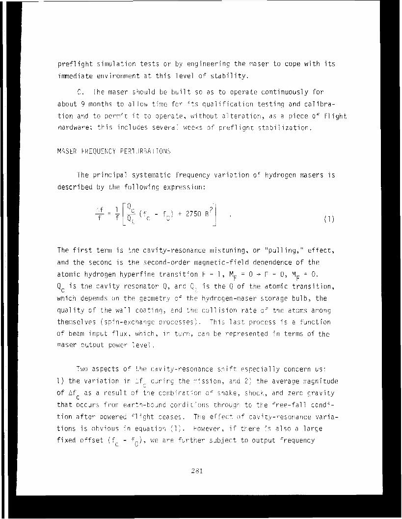
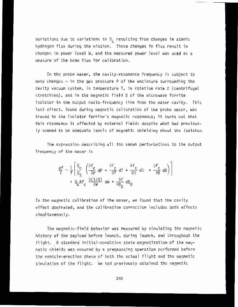
The expression describing a l l the known perturbations t o the output
freauencv of the maser i s
I n the magnetic calibration of the maser, we found that the cavity
effect dominated, and the cal i bration correction incl udes both effects
simul taneously.
The magnetic-field behavior was measured by simulating the magnetic
history of the payload before launch, during launch, and t h r o u g h o u t the
f l ight. A standard ini tial-condition s t a t e magnetization of the mag-
netic shields was ensured by a pregaussing operation performed before
the vehicle-erection phase o f b o t h the actual f l i gh t and the magnetic
simul ation of the f l i g h t . We had previously obtained the magnetic
condit ions froni a survey o f the launch area a n d from nieasurements a t t h e
posit ion of the rnaser in the launcher w h i l e the 1 auncher was being
erec ted . The f i e l d s during l i f t o f f and in to the t r a j e c t o r y were
obtained from eartti f i e l d niodels, arid t h e e f fec t o f t n e spinup of the
probe a t t h e appropriate e a r t h f i e l d i r , i n ~ c ! ~ p o r - a t e d i n the simulat ion.
The simulation of the rap . id asce t i t , it1t.o t he vacljutri ;:~f space was a l so
included a t the appropriate t in)? i n t he sequence.
The magnetic f i e l d ercountered during t h e f l i g h t has been deter-
mined froni standard earth niodels. A t present . only t h e axial component
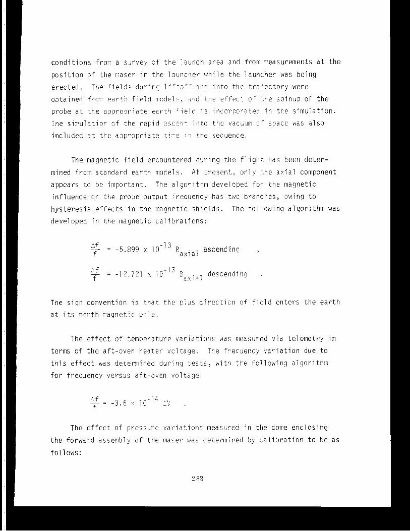
appears to be in~por tant . The a1 gori t h n i developed f o r the magnetic
influence on the probe output frequency $ a s t w o branches, owinq t o
hys teres is e f f e c t s in t h e rriagrietic s h i e l d s . The following algorithm was
developed in the magnetic cal i hra t ions :
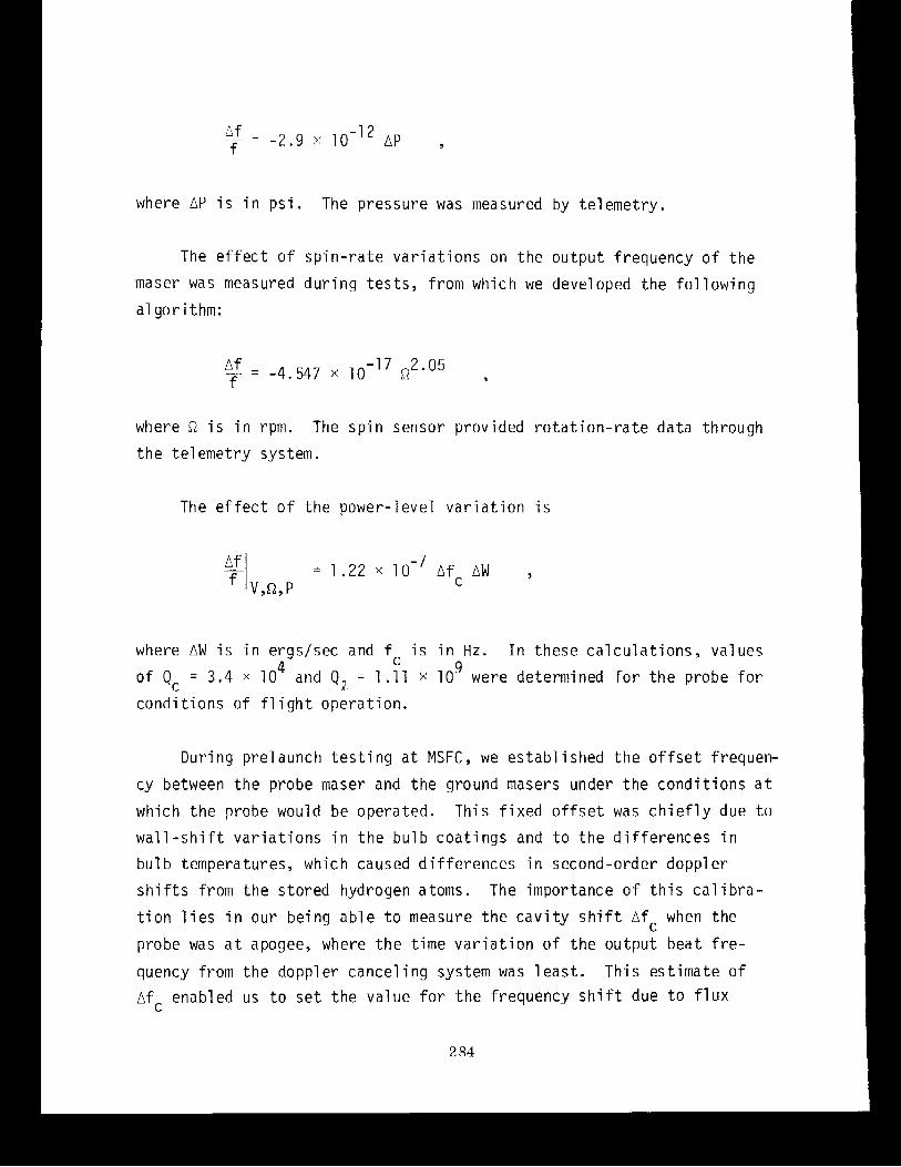
The e f f e c t o f temperature var ia t ions was measured via telemetry in
terms of the aft-oven heater voltage. The frequency va r i a t ion due t o
t h i s e f f e c t was deteniiined during t e s t s , w i t h t.he following algorithin
f o r frequency versus aft-oven voltage:
The e f f e c t of pressure var ia t ions measurea in the dome enclosing
the forward assembly of the Imaser was deterrriined by ca l ib ra t ion t o be as
fol lows:
where AP i s i n p s i . The p ressure was measured by t e l eme t r y .
The e f f e c t of s p i n - r a t e v a r i a t i o n s on t h e o u t p u t f requency of t h e
maser was measured d u r i n q t e s t s , f r om which we d e v e l o ~ e d t h e f o l l o w i n a
where R i s i n rpm. The s p i n sensor p rov ided r o t a t i o n - r a t e da ta through
t h e t e l em2try system.
The e f f e c t o f t h e power- leve l v a r i a t i o n i s
where AW i s i n e rgs lsec and f i s i n Hz. I n these c a l c u l a t i o n s , va lues 4 C 9 o f Qc = 3.4 x 10 and Q p = 1 .ll x 10 were determined f o r t h e probe f o r
c o n d i t i o n s o f f l i g h t ope ra t i on .
Dur ing p re launch t e s t i n g a t MSFC, we e s t a b l i s h e d t h e o f f s e t frequen-
cy between t h e probe maser and t h e ground masers under t h e c o n d i t i o n s at;
which t h e probe would be operated. Th i s f i x e d o f f s e t was c h i e f l y due t o
w a l l - s h i f t v a r i a t i o n s i n t h e b u l b c o a t i n g s and t o t h e d i f f e r e n c e s i n
bu l b temperatures, which caused d i f f e r e n c e s i n second-order doppl e r
s h i f t s f rom t h e s to red hydrogen atoms. The importance o f t h i s c a l i b r a -
t i o n l i e s i n our be ing a b l e t o measure t h e c a v i t y s h i f t A f c when t h e
probe was a t apogee, where t h e time v a r i a t i o n o f t h e ou tpu t bea t f r e -
quency f rom t h e doppler cance l i ng system was l e a s t . T h i s es t ima te o f
A f r enabled us t o s e t t h e v a l u e f o r t h e f requency s h i f t due t o f l u x
,'f ~ changes a s observed frorn power changes g i ven by above. The
V,^,P frequency o f f s e t a t apogee due t o r e l a t i v i t , ~ rrlust be assurrled t o be a s
predicted by the equivalence ~ r i n c i p l e a t sl ightly be t t e r than the 17!,
level f o r t h i s deterrilination. Our f i r s t c u t a t deterniining the cavity
o f f s e t revealed t ha t the cavity was mistuned in frequency by about
-36 Hz, which makes
MECHANICAL DESIGN
The Cavi ty-Bul b S t ructure
The mechanical and thermal requirements o f the cavi ty i t s e l f were *
met bymaking i t of CER-VIT. Details of t h e d e s i g n w i l l follow in l a t e r
sect ions; for the present , we must recognize t h a t t h e overall thermal
coef f i c ien t of the resonance frequency of the cavity-bulb assembly i s
a b o u t -800 Hz/"C.
A t the outse t , we realized t h a t the thernial design o f the maser
would impose a special s e t o f problems, a n d we established very demanding
requirements for temperature e x c u r s i o ~ s a t the c r i t i c a l areas near the
cavity assembly. E s t i i r ~ a t e s o f t o e tetuperature variat ion o n the mounting
points and t h e conditions of rad ia t ive coupling in tc space provided the
boundary conditions f o r computer solution a t MSFC t o help provide design
information t o SAO fo r thermal control of the maser.
T h e maser b u l b i s a 7"-diameter quartz sphere attached t o a
cylindrical rr~ountinq s k i r t , a l s o o f quartz, by four 1 " welds. The
s k i r t , i n t u r n , i s f a s t e n e d t o t h e C E R - V I T end p l a t e b y means o f t o r r -
sea l epoxy. The b u l b c o l l i m a t o r i s i n t e g r a l t o t h e b u l b s t r u c t u r e .
The b u l b i s c o a t e d w i t h FEP-120 T e f l o n . The c a v i t y c y l i n d e r , made
of CER-VIT 101, i s 1 1 " i n d i a m e t e r and 9 112" l o n g and has an 0 .2 " w a l l .
The c a v i t y end p l a t e s a r e p ress moulded o f CER-VIT and have r e i n f o r c i n g
r i b s on t h e o u t e r s u r f a c e s f o r l i g h t n e s s and s t i f f n e s s . A l l i n t e r i o r
c o n d u c t i n g s u r f a c e s o f t h e c a v i t y a r e coa ted w i t h evapora ted copper
abou t 0.0003" t h i c k . T h i s t h i n c o a t i n g i s d u c t i l e and p r e v e n t s t h e
c a v i t y f rom b e i n g d i s t o r t e d b y the rma l expans ion o f t h e copper ,
The c a v i t y i s c u t t o t h e a p p r o p r i a t e l e n g t h and t h e j o i n t s lapped
f o r mechan ica l s t a b i l i t y . Be fo re t h e b u l b end p l a t e was r e l e a s e d f o r
f i n a l assembly, i t was shock and v i b r a t i o n t e s t e d under vacuum t o v e r i f y
t h e i n t e g r i t y of a l l j o i n t s - p a r t i c u l a r l y t h o s e between t h e q u a r t z c y l -
i n d e r and t h e sphere . The c a v i t y i s assembled w i t h i n t h e vacuum e n c l o -
sure , as shown i n F i g u r e 2, b y u s i n g a s p e c i a l p ress t h a t f o r c e s t h e
upper end o f t h e vacuum t a n k t o c l o s e a g a i n s t t h e B e l l v i l l e s p r i n g . The
p r e v i o u s l y c a l i b r a t e d b e h a v i o r o f f o r c e v s . d e f l e c t i o n i n t h e s p r i n g was
v e r i f i e d d u r i n g assembly by o b s e r v i n g t h e c a v i t y resonance as t h e s p r i n g
was compressed. The CER-VIT c a v i t y i n t h i s case a c t e d as a l o a d c e l l t o
m o n i t o r t h e a p p l i e d f o r c e . When a p p r o p r i a t e l o a d and d e f l e c t i o n were
ach ieved, t h e vacuum t a n k was welded s h u t and t h e t a n k was removed f rom
t h e p r e s s .
The l o w e r p a r t o f t h e c a v i t y i s suppor ted b y 12 b e r y l 1 ium copper
(BeCu) t a n g e n t i a l l y o r i e n t e d r o l l e r s sea ted on a hardened BeCu r i n g t o
a l l o w f o r d i f f e r e n t i a l thermal expans ion o f t h e aluminum t a n k cove r and
t h e CER-VIT. I n t h e upper assembly, t h i s f u n c t i o n i s done b y t h e Be1 l-
v i l l e s p r i n g , The vacuum t a n k h a s an access p o r t f o r c a v i t y f i n e t u n i n g
by means o f a mechan ica l ad jus tmen t . E l e c t r o n i c f i n e t u n i n g i s done v i a
a l o o p and v a r a c t o r d i o d e l o c a t e d i n t h e l o w e r c a v i t y end p l a t e . D ia -
p r i n t e d - c i r c u i t c a r d s . The t e m p e r a t u r e - s e n s i t i v e e l e c t r o n i c s a r e p l a c e d
on t h e oven c o v e r j u s t f o r w a r d o f t h e m idp lane p l a t e , w i t h i n t h e tempera-
t u r e - c o n t r o l l e d zones p r e v i o u s l y d e s c r i b e d . The r e m a i n i n g bay, wh ich has
a t e s t connec to r a t i t s o u t e r m o s t r a d i u s , se rves t o pass i n t e r c o n n e c t i o n s
between t h e f o r w a r d and t h e a f t assemb l ies . The bays a r e t h e n covered
w i t h an 0 . 0 6 2 " - t h i c k aluminum p l a t e on wh ich t h e a n c i l l a r y equipment a f t
o f t h e m idp lane p l a t e i s mounted. The aluminum p l a t e p r o v i d e s a p r e c i s -
i o n o u t s i d e d i a m e t e r t o engage a b o r e i n t h e s p a c e c r a f t " moun t ing p l a t e
so t h a t , when t h e two p l a t e s a r e mated, r a d i a l d e f i n i t i o n i s e s t a b l i s h e d
i n two p lanes . The m idp lane p l a t e a l s o has 12 moun t ing h o l e s f o r s e c u r -
i n g t h e exper imen t i n t h e t h r u s t a x i s . F i g u r e 9 shows t h e p l a t e w i t h i t s
w i r e harness.
The Vacuum M a n i f o l d
The a f t vacuum assembly ( see F i g u r e 10) i s a two-pump system: an
SAES G e t t e r s ( I t a l y ) Sorbac c a r t r i d g e shown i n F i g u r e 11 and a V a r i a n
0 . 2 - l i t e r i o n pump. The fo rmer pump, which works by c h e m i c a l l y e n t r a p -
p i n g hydrogen atoms t o f o r m h y d r i d e s o f z i r c o n i u m , i s t h e p r ime hydrogen
pump. I f t h e c a r t r i d g e s h o u l d become s a t u r a t e d , i .e., unab le t o pump
hydrogen, i t can be r e g e n e r a t e d by h i g h - t e m p e r a t u r e bakeou t b y a p p l y i n g
an e x t e r n a l v o l t a g e t o i t s i n t e r n a l r e s i s t a n c e h e a t e r and b y c o n n e c t i n g
t h e maser t o a l a b o r a t o r y pumping system t o remove t h e r e l e a s e d hydrogen.
The 0 . 2 - l i t e r i o n pump i s used f o r nob le-gas pumping, I t s c a p a c i t y
i s s u f f i c i e n t t o m a i n t a i n a system p r e s s u r e o f l e s s t h a n 1 x t o r r
f o r t h e 9 months b e f o r e l aunch . The i o n pump a l s o se rves as a p r e s s u r e
gauge f o r t h e evacuated enve lope s i n c e t h e i o n c u r r e n t can be c o r r e l a t e d
w i t h gas p ressu re .
The a f t vacuum assembly a l s o c o n t a i n s a hexapo le magnet, moun t ing
p o r t s f o r t h e P i r a n i gauges, and i o n i z a t i o n g lassware and hydrogen-
i n t r o d u c t i o n appara tus .
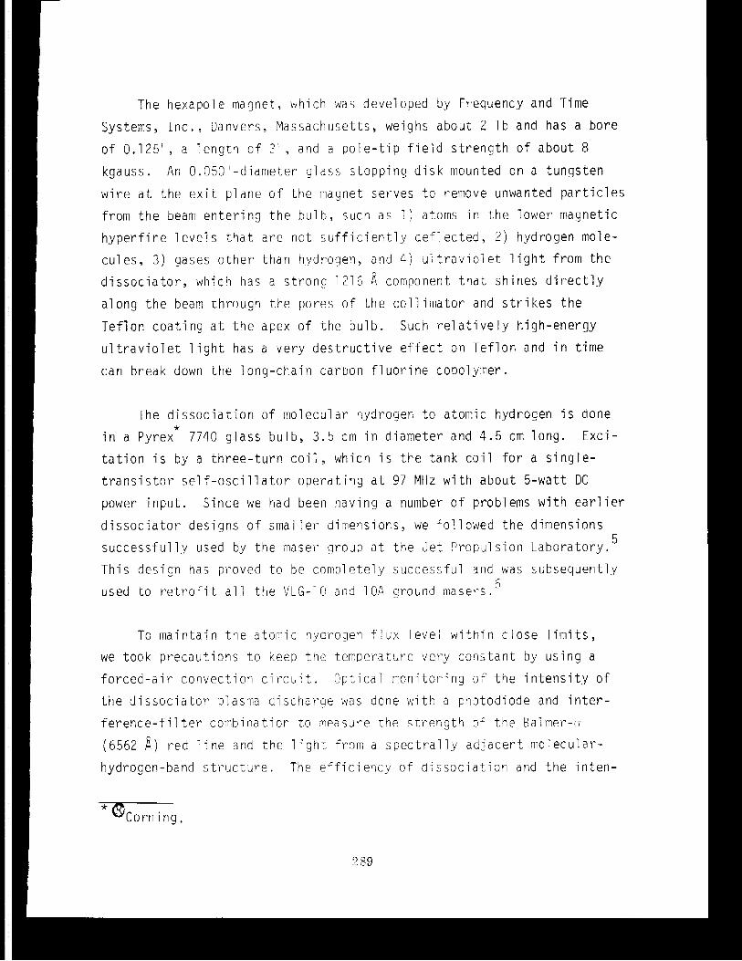
The hexapol e magnet,, w h i ch was devel oped by Frequency and Time
Systems, I n c . , Danvers, Massachusetts, weighs about 2 1 b and has a bore
o f 0.125", a length of 3 ' ' , a n d a pole- t ip f i e l d s t rength of about 8
kgauss. A n 0.050"-diameter g l a s s stopping d isk mounted on a tungsten
wire a t the e x i t plane of the magnet serves t o remove unwanted p a r t i c l e s
from the beam enter ing the bulb, such as 1 ) atorr~s in the lower magnetic
hyperfine l eve l s t h a t a re n o t s u f f i c i e n t l y def lec ted , 2 ) hydrogen mole-
cules , 3 ) gases o ther t h a n hydrogen, a n d 4 ) u l t r a v i o l e t l i g h t from the
d i s s o c i a t o r , which has a s t rong 1216 b con~ponent t h a t shines d i r e c t l y
along the beam through the pores of the coll imator a n d s t r i k e s t h e
Teflon coating a t the apex of the bulb. Such r e l a t i v e l y high-energy
u l t r a v i o l e t l i g h t has a very des t ruc t ive e f f e c t o n Teflon and in time
can break down the long-chain carbon f luor ine copolymer.
The d issocia t ion of molecular hydrogen t o atomic hydrogen i s done *
in a Pyrex 7740 g lass bulb, 3 . 5 cm in diameter and 4 . 5 cm long. E x c i -
t a t i o n i s by a three-turn c o i l , which i s the tank coi l fo r a s ing le -
t r a n s i s t o r s e l f - o s c i l l a t o r operat ing a t 97 MHz with about 5-watt DC
power input . Since we had been having a number of problems with e a r l i e r
d i s soc ia to r designs of smaller dimensions, we followed the dimensions
successful ly used by the tiiasei- group a t the J e t Propulsion Laboratory. 5
This design has proved t o be completely successful a n d was subsequently
used t o r e t r o f i t a l l the V L G - 1 C i a n d 10A ground rriaser-s. 6
To maintain the atoriiic hydrogen f lux level within c lose 1 imi t s ,
we t o o k precautions t o keep t h e temperature very constant by using a
forced-a i r convection c i r c u i t . Optical n~onitoring o f the i n t e n s i t y o f
the d i s soc ia to r plasma discharge was done with a photodiode a n d i n t e r -
f e r e n c e - f i l t e r coinbination t o measure the s t rength ~f the Galrner-:)
(6562 1) red l i n e and the l i g h t fro111 a s p e c t r a l l y adjacent molecular-
hydrogen-band s t r u c t u r e . The ef f ic iency of d issocia t ion and the inten-
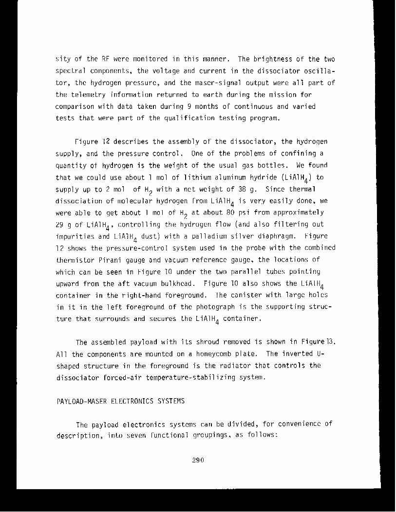
s i ty of the R F were monitored in th i s manner. The brightness of the two spectral components, the vol tage a n d current in the dissociator osci l la-
t o r , the hydrogen pressure, and the maser-signal o u t p u t were a l l part of
the telemetry information returned t o earth during the mission for
comparison with d a t a taken during 9 months of continuous and varied
t e s t s t h a t were part of the qualification test ing program.
Figure 1 2 describes the assembly o f the dissociator, the hydrogen
supply, and the pressure control. One of the problems of confining a
quantity of hydrogen i s the weight of the usual gas bot t les . We found
that we could use about 1 mol of 1 ithium aluminum hydride (LiA1H4) t o supply up t o 2 mol of H 2 with a net weight of 38 g . Since thermal
dissociation of molecular hydrogen from LiA1H4 i s very easi ly done, we
were able t o get about 1 mol of HE a t a b o u t 80 psi from approximately
29 g of LiA1H4, controlling the hydrogen flow (and also f i l t e r ing out
impurities and LiA1H4 dust) with a p a l 1 adium s i lver diaphragm. Figure
1 2 shows the pressure-control system used in the probe with the combined
thermistor Pirani gauge a n d vacuum reference gauge, the locations of
which can be seen in Figure 10 under the two parallel tubes pointing
upward from the a f t vacuum bulkhead. Figure 10 a1 so shows the LiAlH4
container in the right-hand foreground. The canister with large holes
in i t in the l e f t foreground of the photograph i s the supporting struc-
ture t h a t surrounds and secures the LiAlH4 container.
The assembled payload with i t s shroud removed i s shown in Figure 13.
All the components a re mounted on a honeycomb plate. The inverted U-
shaped structure in the foreground i s the radiator t h a t controls the
dissociator forced-air temperature-stabilizing system.
PAYLOAD-MASER ELECTRONICS SYSTEMS
The payload electronics systems can be divided, for convenience of
description, into seven functional groupings, as fol lows:
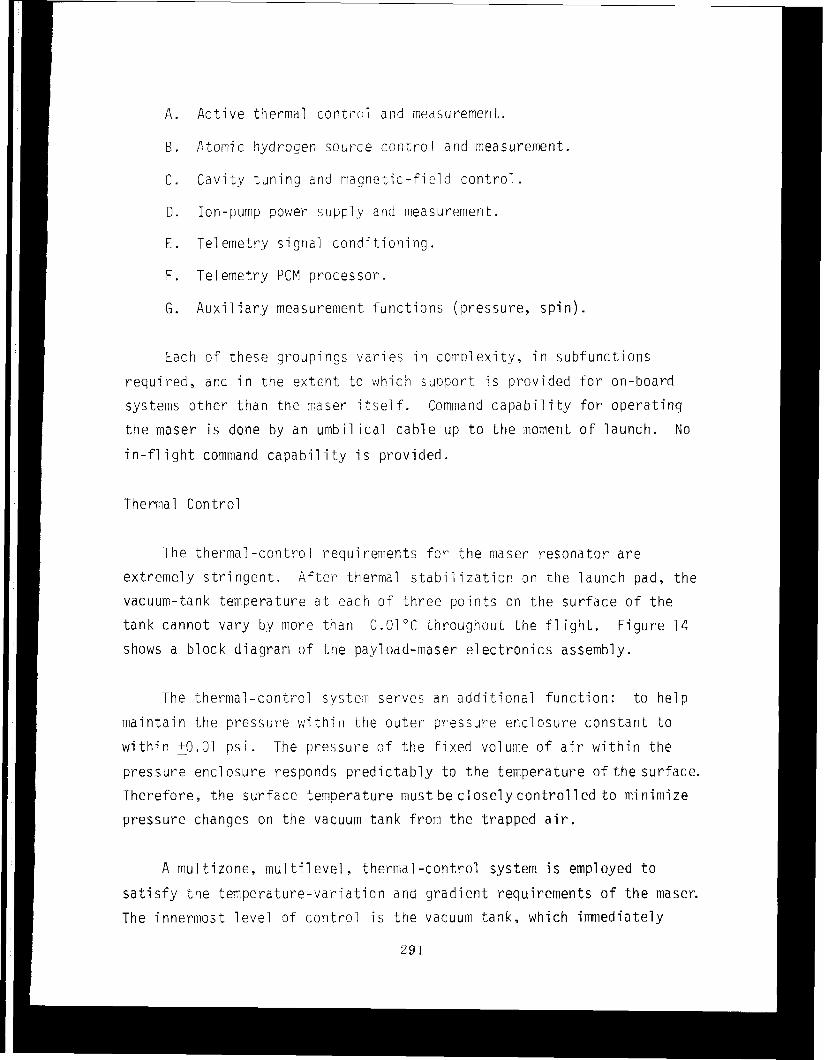
A . Active thermal coritrol a n d measurement.
6 . Atornic hydrogen source control and measurement.
C . Cavity tuning a n d magnetic-field con t ro l .
D . Ion-pump power supply and tmeasurement.
E . Tel ernetry signal conditioning . F . Tel emetry PCM processor.
G . Auxil i a ry measurement functions (pressure , s p i n ) .
Each of these groupings var ies in cotiiplexity, in subfunctions
requi red , and in the extent t o which support i s provided f o r on-board
systei~is other t h a n the maser i t s e l f . Comrriand capabi 1 i t y for operating
the maser i s done by a n umbilical cable u p t o the moment of launch. No
in- f l i gh t command capabil i t y i s provided.
Thermal Control
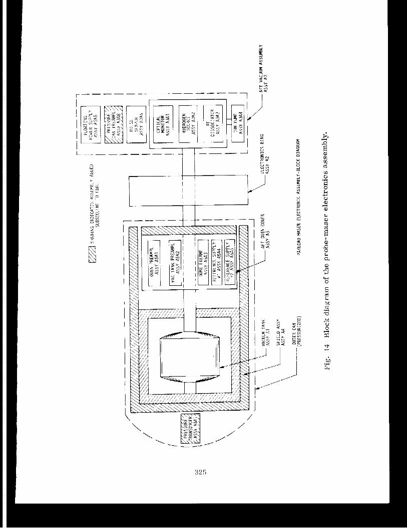
The thermal -control requi renients fo r the maser resonator a r e extret~iely s t r i n g e n t . After thermal s t a b i l i z a t i o n on the launch pad, the
vacuum-tank temperature a t each of three points on the surface of the
t a n k cannot vary by more than 0.01 "C throughout the f l i g h t . Figure 74
shows a block diagram of the pay1 oad-maser e l ec t ron ics assembly.
The thermal-canti-01 syste~rl serves an addit ional function: to h e l p
maintain the pressure within the outer pressure enclosure constant t o
within g . 0 1 ps i . The pressure of the f i x e d volume o f a i r within the
I pressure enclosure responds predictably t o the teniperature o f t h e surface.
Therefore, the surface temperature must be close ly control 1 ed t o mi niniize
pressure changes on the vacuum tank from the trapped a i r .
i s a t i s f y the temperature-variat ion and gradient requirements of the maser. I The innermost level of control i s the vacuunl t a n k , which immediately
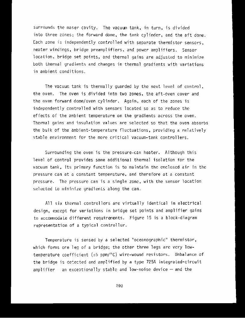
surrounds the maser cavity. The vacuum tank, in turn, i s divided
into thrze zones: the forward dome, the tank cylinder, and the a f t dome.
Each zone i s independently controlled with separate thermistor sensors,
heater windings, bridge preamplifiers, and power amplifiers. Sensor
location, bridge set points, and thermal gains are adjusted t o minimize
b o t h thermal gradients and changes in thermal gradients with variations
in ambient conditions.
The vacuum tank i s thermally guarded by the next level of control,
the oven. The oven i s divided into two zones, the aft-oven cover and
the oven forward domeloven cylinder. Again, each of the zones i s
independently controlled with sensors located so as to reduce the
effects of the ambient temperature on the gradients across the oven.
Thermal gains and insulation values are selected so that the oven absorbs
the bul k of the ambient-temperature fluctuations, providing a re1 atively
s table envi ronment for the more c r i t i ca l vacuum-tank controllers.
Surrounding the oven i s the pressure-can heater. Although th i s
level of control provides some additional thermal isolation for the
vacuum tank, i t s primary function i s to maintain the enclosed a i r in the
pressure can a t a constant temperature, and therefore a t a constant
pressure. The pressure can i s a single zone, with the sensor location
selected to minimize gradients along the can.
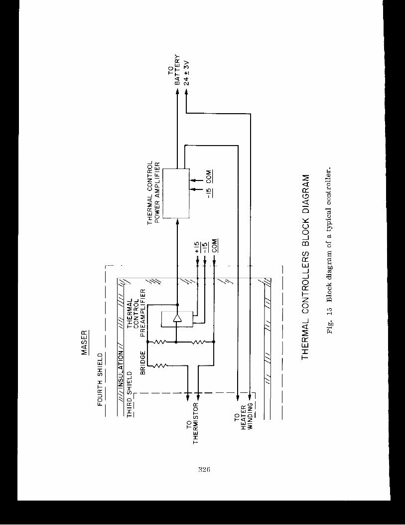
A1 1 s ix thermal control l e r s are vir tual ly identical in electr ical
design, except for variations in bridge se t points and amplifier gains
t o accommodate different requirements. Figure 15 i s a block-diagram
representation of a typical control 1 er .
Temperature i s sensed by a selected "oceanographic" thermistor,
which forms one leg of a bridge; the other three legs are very low-
temperature coefficient (+5 ppmI0C) wi re-wound resis tors . Unbalance of
the bridge i s detected and amplified by a type 725A integrated-circuit
amplifier - an exceptionally stable and low-noise device - and t h e
output of the 725A i s fed b a c k t o the bridge. The feedback i s posi t ive
when the bridge i s f a r off balance, producing an " in f in i t e -ga in" o r
s e l f -o sc i l l a t i ng con t ro l l e r . Close t o balance, the preamplifier i s a t rue proportional con t ro l l e r with ant ic ipatory feedback.
All the preamplif iers , with the exception of the pressure-can
un i t , a r e mounted on the aft-oven cover shown i n Fiqure 7 . This vol ume
s t a b i l i t y of the con t ro l l e r s and minimizing spurious thermoelectric and
thermocouple voltage var ia t ions on the thermistor leads.
Each o f the preamplifiers feeds a pulse-width-modulated power
amplif ier with a maximiim power capabi l i ty of 11 watts a t minimum battery
voltage. The pul se-width-rnodul ated amplif iers operate a t a constant
pulse r a t e of approximately 40 kHz; the width o f the pulses i s propor-
t ional t o the amp1 i f i e r input voltage. Thus, the average output voltage
i s d i r ec t l y proportional to the input voltage, although the power tran-
s i s t o r s a r e always operating in a pulse mode, f u l l y o n or o f f . The
output of the amplif ier i s ca re fu l ly f i l t e r e d a t the output o f the f inal
power s tage so t ha t only the DC component appears across the o u t p u t
The switching amp1 i f i e r i s qui te col~ipact and e f f i c i e n t . Overall
ef f ic iency i s greater than 80. a t f u l l load, independent o f voltage over
the allowable variat ion i n bat tery voltage. Tne high eff ic iency
eliminates the requirement f o r a rllassive heat ;Ink for the power
t r an s i s t o r and permits i t t o be mounted d i rec t ly t o the anlpl i f i e r ' s
pr in ted-ci rcui t board. This arrangement s impl i f ies the interconnection
wiring and permits the construction o f a simple, readi ly shielded
I amp1 i f i e r assembly.
The s i x thermal-control power ainlsl i f i e r s a re mounted on pie-shaped
provides a thermal conduction path t o the frame of the payload.
The pressure-can preamplif ier , which has a much lower s t a b i l i t y
requirement than the oven or vacuum-tank con t ro l l e r s , i s mounted on the
a f t vacuum assembly.
Thermal Controller Performance
The temperature s e n s i t i v i t y of the thermal-control preamplifiers
has been bench tes ted over a O0 t o 60°C range. The maximum a1 lowable
variat ion in bridge-balance temperature i s O.OOl°C per degree of ambient-
temperature change. Typical values a re in the order of O.OOO1°C/OC,
ensuring t ha t the temperature s e n s i t i v i t y of the preamplifiers in the
+ l a c aft-oven-cover area does not contribute s ign i f i can t ly t o the - overall temperature s e n s i t i v i t y cf the payload maser.
Under more r e a l i s t i c conditions in the thermal-vacuum t e s t s , the
thermal-control system maintains the vacuum tank within +O.Ol°C under
a l l t e s t conditions.
RF Osci 1 1 a t o r Control
The variable-vol tage supply f o r the osci 11 a t o r co l l ec tor i s
furnished by a pulse-width-modulated power amplif ier functionally and
physically ident ica l t o those used in the thermal-control system. The
control voltage fo r the power ampl i f ier i s generated by the coarse-
control c i r cu i t r y , a l so located on a printed-circui t board in the elec-
t ronics r ing. The source control i s e ssen t ia l ly a 4-bit d ig i t a l - t o -
analog converter i n which the four d ig i t a l switches a r e magnetically
latched re lays . The relays a re s e t and r e se t only from the external
ground-station equipment. Subsequent payload power in terrupt ions o r
t r ans ien t s cannot a f f e c t the s t a t e of the re lays .
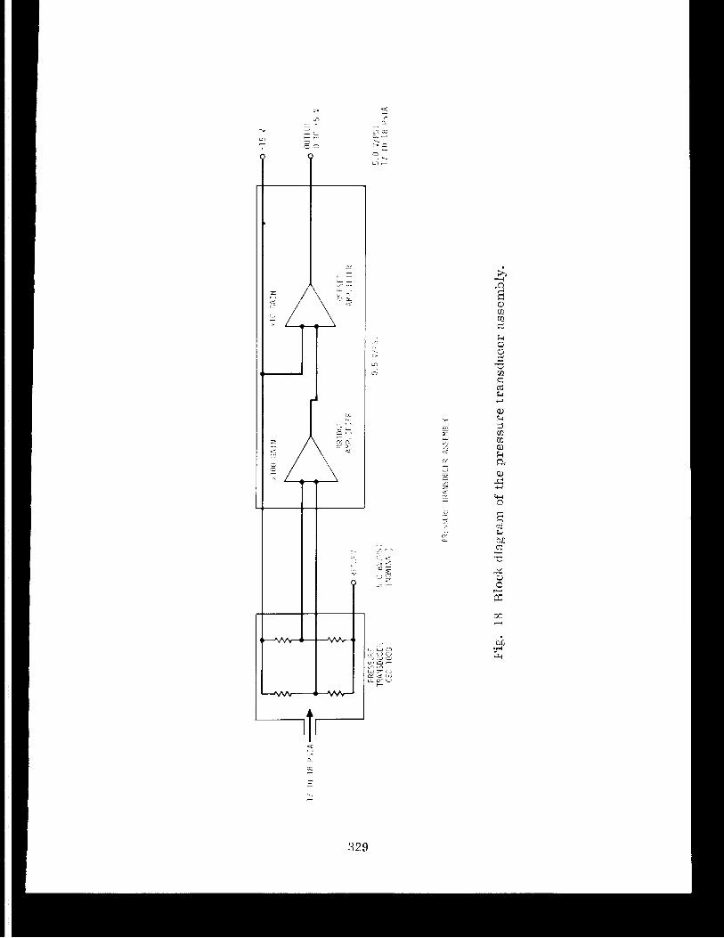
Hydrogen Pressure Servo
The pressure of the molecular hydrogen gas i s in the range of about
1 to 2 n i i l l i to r r and regulated by a closed-loop servo system. The
pressure of the gas i s sensed by a Pirani qauge a t a point j u s t before
the gas l i n e enters the dissocia tor bulb. The Pirani gauge i s a small
thermistor bead suspended in the gas vol urne on two very slender, 0.00lU,
wires. The thermistor f o r m s one leq of a self-balancing bridge. The
bridge c i r c u i t r y causes su f f i c i en t current t o flow through the bead to
make the bead temperature r i s e to approximately 200°C; a t t h i s tempera-
tu re , the res is tance of the bead i s such t h a t the bridge i s balanced.
A t very low pressure, l i t t l e current i s required to balance the bridge;
a t higher pressures, the thermal conductivity of the gas i s increased
and higher current i s required t o balance the bridge. Thus, the
current required t o balance the thermistor bridge i s , f o r a given
species of gas, a d i r e c t measure of the gas pressure. I n order t o
minimize the e f f ec t s of ambient-tetzperature v a r i a t ~ o n s of the gas-pres-
sure ~;~easurement, a second self-balancinq reference bridge i s provided.
This reference Pirani gauge, which i s special ly matched t o the measure-
ment Pi rani , i s i n s t a l l ed in the high-vacuum s ide of the vacuum system
and exposed t o the same ambient tenlperature as the measurement Pi rani .
Fluctuations in bridge current are e lec t ron ica l ly subtracted from the
nieasurenient bridqe current to provide a temperature-compe~isated pressure-
measurement output .
The pressure-measurement o u t p u t serves two functions; f i r s t , the
output level i s conditioned and used fo r telemetry monitoring o f hydro-
gen pressure, and second, i t forms one input t o the pressure cornpara-
t o r . The other input t o the pressure comparator i s the pressure-set-
point voltage, which i s controlled fro111 the GSEE. The pressure
comparator provides a voltage o u t p u t proportional t o the d i f ference
between the measured pressure and the pressure s e t point , This voltage
output, in turn , serves as the input t o t h e pressure power amplif ier .
295
The power amp1 i f i e r , identical t o the thermal-control power amp1 i f i e r s ,
regulates the power input t o the LiA1H4 heater and thus completes the
feedback loop. The voltage across the can i s t e r heater i s monitored
through the telemetry-signal conditioning system and provides a contin-
uous telemetry record of can i s te r heater power.
The pressure-set-point voltage i s generated by a 5-bi t d i g i t a l -
to-analog converter. The d i g i t a l switches a r e magnetically latched
relays t h a t can be operated only from the G S E E system. The two s e l f -
balancing bridges, the pressure comparator, and the 5-b i t d ig i t a l - to-
analog converter a re mounted on the pressure-control assembly, which,
in t u r n , plugs i n to the e lec t ronics r ing.
Optical Moni t o r
The hydrogen-gas discharge in the d i s soc ia to r bulb must be moni-
tored t o obtain information as t o the s t a t e of d issocia t ion in progress.
Two photodetectors are a subs t i t u t e f o r d i r ec t observation and provide
a quan t i t a t ive , objective measurement of the qual i ty and brightness of
the discharge. Each photodetector i s an integrated photodiode-amplifier
device.
Both the "atomic" and the "molecular" outputs of the opt ica l
monitor are signal conditioned and processed fo r telemetry transmission.
Cavity Tuning and Magnetic-Field Control
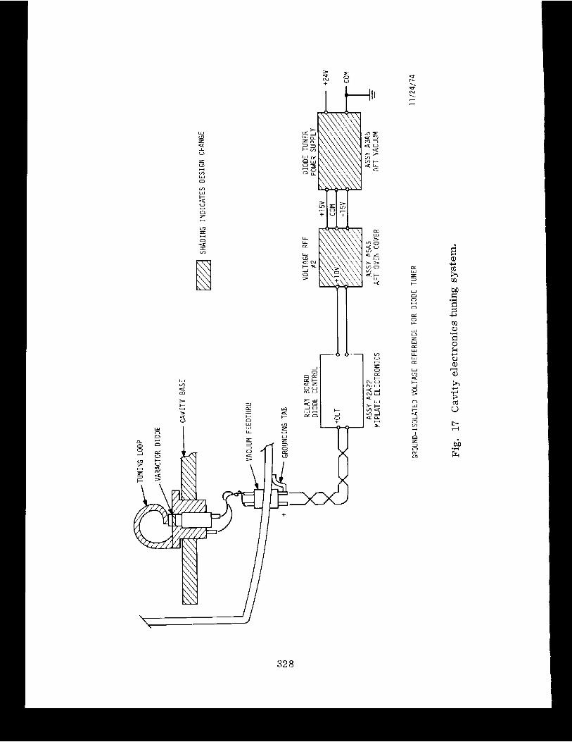
The maser cavi ty i s tuned by varying the reverse voltage on a
varactor diode mounted within the cavi ty . The uniform magnetic f i e l d
imposed on the cavi ty and storage-bulb area i s adjusted by varying the
current through a main f i e l d winding and two trim windings on the
pr in ted-ci rcui t solenoid. These four con t ro l l e r s , one tuning and three magnetic f i e l d , a r e a l l physically identical and a l l a r e i n s t a l l ed in
the e lec t ron ics r ing.
296
-
digital-to-analog converters, each physically identical t o the cavity-
tuning controller described above.
Since each winding has a very low resistance, less than 10 ohms, the
0- t o 10-volt range of the voltage divider i s converted t o 0- t o 1-mA
current by the addition of a 10-kilohm thin-film res is tor . An additional
relay, n o t used for the cavity-tuning function, reverses the direction of
current flow through the solenoid winding. All 11 magnetically latching
relays are controlled direct ly from the payload GSEE. As before, no
switching capabili ty i s available a f t e r the umbilical cable i s removed
from the spacecraft.
The 10-bit controller provides an o u t p u t of 0 t o 1 mA th rough the
winding with a resolution of approximately 10 PA per b i t . S tab i l i ty o f
the current i s determined principally by the temperature coefficient of
resistance of the ser ies res i s tor , approximately 50 ppm/"C, over the
range 0" t o 60°C.
Ion-Pump Power Supply and Measurements
The appendage ion pump requires a power source furnishing approxi-
mately 2500 volts a t 50 PA maximum. A small D C - t o - D C converter, manu-
factured by MIL Electronics, Lowell , Massachusetts, i s mounted direct ly
to the pump bracket. The power-supply high-voltage terminal i s adjacent
t o the pump feedthrough, and the ent i re high-voltage cavity i s potted
with a si l icone rubber compound a f t e r wiring.
The power supply i s regulated a t 2500 volts 5% over an input
voltage range of 24 + 3 vol ts . Current i s electronically limited t o
50 uamp by internal protective c i rcu i t ry .
The ion-pump current, which i s also a means for measuring the
condition o f the vacuum, i s monitored by measuring the voltage across a
298
t ranslator AGC signal conditioner contains provisions for selecting a
small segment of the t ranslator AGC output and expanding th i s portion to
the fu l l 0- t o 5.0-volt range. The final adjustment of the translator
AGC signal -conditioning c i rcu i t ry provides a fu l l -scale range from -1 16
t o -110 dbm, established during cal ibration of the probe maser.
Eight channels of voltage measurements are provided for battery
vol tage, battery current, and s i x payload-maser heater voltages.
Three channels for in-fl ight calibration checks of the telemetry
system are included: fu l l scale , +4.980 volts; midscale, +1 -00 volts;
and ground.
Six measurement channels t o monitor maser performance are also
incorporated. Two of these monitor the voltage and current o f the
source RF osc i l la tor . The remaining four - hydrogen pressure, ion-pump
current, "atom" 1 evel , and "molecule" 1 evel - were discussed in previous
sections.
The payload-maser signal-conditioning subsystem provides reference
voltages and buffer amplifiers for t h e Scout fourth-stage head pressure
gauge. The three Scout fourth-stage accelerometers are internally con-
ditioned; the i r outputs a re routed t h r o u g h the signal conditioner t o the
tel ernetry processor.
Telemetry PCM Processor
The telemetry processor i s an 8 -b i t , 37-channel pulse-code-modulated
(PCM) system operating a t 1000 bps. Each main frame has eight subframes
128 b i t s in length: 21 providing subframe sync, 3 giving subframe iden-
t i f i ca t ion ( I D ) , a n d 104 making u p 13 8-bit data words. I n turn, four
data words are mu1 tip1 exed, yielding 32 channels per main frame. The
remaining five data words are used for high-repetition-rate data as
300
follows: the t r a n s l a t o r A G C voltage i s sampled once each subframe ( e i g h t
times each main f rame) , and the four Scout channels a re sampled twice
each subframe ( 1 6 tirrles f o r each rnai n frame) .
The rrlajor cor~iponents of t h ~ telemetry processor cons i s t of an
analog-to-digi t a l conver ter , a main-frame m u 1 t i plexer, f o u r subfrdme
mul t ip iexers , and a timing and sync generator-.
A1 1 t e l emetry-processor c i r c u i t r y i s mounted on e igh t pie-shaped
boards t h a t plug in to the e l ec t ron ics r ing . The processor ' s tinling
c i r c u i t r y generates the fol lowing clock s igna l s f o r the telemetry system:
the b i t - r a t e clock (1000 b p s ) , the coordinate clock (125 bps) , and the
subframe clock (7.8125 b p s ) , A l l clocks are derived from, and harmonic-
a l l y r e l a t ed t o , the subcar r i e r o s c i l l a t o r frequency of the t ransponder ' s
telemetry modulator.
The subcarr ier c rys ta l o s c i l l a t o r in the transponder generates a
2.048-MHz s igna l , which, divided by 2 w i ~ h i n the transponder, generates
the 1.024-MHz telemetry subcar r i e r . The 2.048-MHz signal i s a lso routed
through the rnaser/spacecraft in t e r face t o the pulse-shaper hoard, which
amp1 i f i e s the s i gnal and regenerates standard +lo-vol t C O S / M O S l ogic
l eve l s . The 2.048-MHz siqnal i s then d i q i t a l l y divided t o 1000 Hz by
COS/MOS integrated c i r c u i t s 9 n the p u l se-stla per board. The 1000-Hz
clock i s routed t o the telemetry timincj board in the e l ec t ron ics r ing .
The pulse shaper contains a n aux i l i a ry o s c i l l a t o r operating a t
approximately 1980 H z . A clock detec tor on the pulse shaper de tec t s the
absence of an incoming pulse streall1 fro111 the transponder and autoniatic-
a l l y switches the aux i l i a ry o s c i l l a t o r on l ~ n e . The aux i1 ia ryosc i l1a to r
frequency i s divided by 2 , t o 990 Hz, t o replace tne divided subcarr ier
o s c i l l a t o r signal f o r t e s t i n g or in the event of subcar r i e r -osc i l l a to r
f a i 1 ure.
SO1
The telemetry timing board, in the electronics ring, consists of
several C O S I M O S divider chains, delay c i r cu i t s , and buffer amplifiers,
which generate a1 1 clock frequencies required for tel emetry-system
operation. In addition t o the major clock signals, the timing board
generates a number of auxiliary clocks t h a t a re either delayed in time
with respect t o the main clock or have suppressed pulses for internal
system timing applications.
The sync board generates the subframe sync and subframe ID words
under control of the timing subsystem. The subframe sync word i s a
standard Goddard Space Flight Center 21-bit code; the subframe ID i s a 3-bit octal word. The subframe sync word i s stored in a 21-bit parallel-
in , serial-out sh i f t regis ter . The b i t pattern i s hard-wired into the
parallel-input parts. The sync board also accepts d a t a input from the
analog-to-digital converter board, assembling the sync word, subframe ID,
a n d d a t a words into a single b i t stream a t a uniform 1000-bps rate .
The analog-to-digital converter digi t izes 0- t o +5-volt data into 8-
b i t data words t h a t a re stored in serial-output sh i f t regis ters . The
converter i s a completely integrated, 256-level, successive-approximation
c i r cu i t , requiring 13 digi t iz ing clock cycles for a single digi t iz ing
operation. To permit the converter to complete a full cycle of opera-
tion in less t h a n eight main-clock cycles, the digi t iz ing clock runs a t
32 kbps, derived from the timing-board divider chains. The +4.980-volt
reference for the analog-to-digital converter i s generated on the scurce-
control/telemetry reference board. The s table +10.0 volts required for
operation of th i s board, in turn, i s generated by a separate reference
supply, which i s instal 1 ed on the temperature-control 1 ed aft-oven cover.
The main-frame mu1 t iplexer accepts 13 analog (0 t o +5.0 vol ts)
inputs - four from the subframe mu1 t iplexers, one from the t ranslator
A G C signal conditioner, and two from each of four Scout measurements -
and switches i t s o u t p u t t o each input in succession. The switching

voltage i s controlled t o within -. +10 mvolts t o minimize self-heating
errors i n the bridge balance point. The bridge amplifier, an Analog
Devices type AD521 S instrumentation amp1 i f i e r , has a very low-vol tage
offset coefficient and a high common-mode-rejection r a t io . The ent i re
assembly i s temperature controlled t o better than y°C owing t o i t s
location within the pressure-can heater system.
The required resolution i s obtained by 1 imiting the dynamic range
of the measurement t o 1.0 psi so as t o operate from 1 7 t o 18 psia. I n
order t o obtain 0-volt o u t p u t from the pressure monitor a t 1 7 psia, i t
i s necessary t o of fse t the bridge amplifier electronically. The effect
of changes in the offset voltage on the overall s t ab i l i t y of the pres-
sure measurement i s minimized by using the bridge excitation voltage as
the source of the offset voltage. To f i r s t order, changes in the exci-
tation voltage cancel completely a t 17 psia and produce only a very
small residual error a t 18 psia. The resolution of the system, as
observed through the 8-bi t telemetry system, i s approximately 0.004 psi
per step of the least-significant d ig i t .
-1 4 The sens i t iv i ty of maser frequency i s approximately 1 x 10 /rpm
a t 115 rpm. A very high-resolution spin-rate monitor i s therefore
required; unfortunately, however, the actual in-fl ight spin ra te cannot
be accurately predicted.
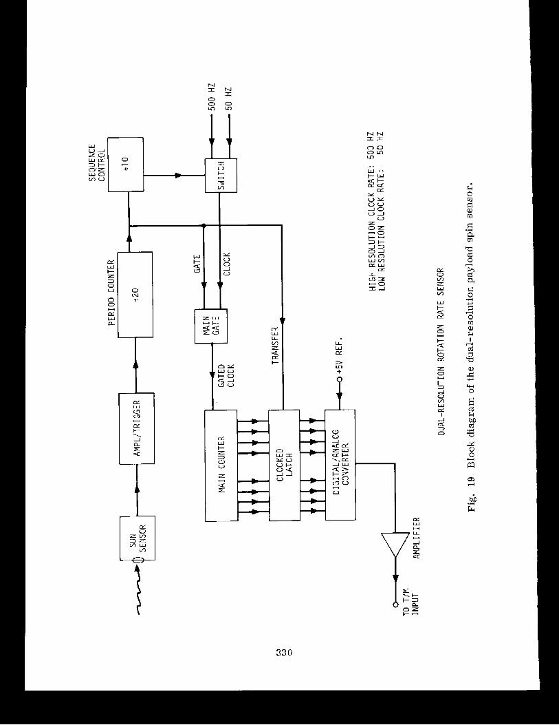
The problem of combining high resolution with a wide dynamic range
i s solved by a sun-sensing dual-resolution monitor t h a t automatically
switches from high resolution t o a wide-range low-resolution mode for
every tenth measurement. A block diagram of th i s monitor i s given in
Figure 1 9 . The sun sensor shown in the figure i s mounted on the space-
c raf t honeycomb plate , where i t views the sun and the outside world
through a small hole in the side of t h e thermal shield. Each time the
vehicle rotation brings the sun into the f i e ld of view of the sensor, a
pulse i s generated, amp1 i f i ed , and used t o energize a Schmi t t tr igger
minimized by using a small f u l l - s c a l e range, a p rec i se re ference deriveti
from the telemetry re ference board f o r the d i g i t a l -to-anal og-converter
re ference vol tage , and t h e c rys t a l - con t ro l l ed subca r r i e r o s c i l l a t o r a s
t h e source of the 1000-Hz main counter clock.
As noted e a r l i e r , t h e sp in sensor i s mounted on t h e s p a c e c r a f t ' s
main honeycomb p l a t e and i s thus t h e only component of the maser e l ec -
t r o n i c s system t h a t i s not phys ica l ly i n s t a l l e d on the maser i t s e l f .
The r e so lu t ion of t h e sp in sensor , i n i t s design range, i s approximately
+0.02 rpm; the est imated ove ra l l accuracy i s approximately 0.05 rpm, - including t h e quant iz ing e r r o r .
Payload Ground Support Elec t ronics Equipment
Two major items of equipment a r e required f o r d i r e c t support of t h e
payload maser during q u a l i f i c a t i o n t e s t s and on t h e pad before launch;
t hese a r e t h e payload control rack and the SAO frequency s tandard , both
o f which a r e i n s t a l l e d i n t h e support t r a i l e r bsed f o r normal operat ions.
The payload control rack houses f a c i l i t i e s f o r opera t ing t h e r e l a y s in
t h e payload f o r f i e l d , source, and cav i ty during c o n t r o l , f o r decoding
spacec ra f t te lemetry , and f o r d isp laying quick-1 ook d i g i t a l and analog
da ta of s e l ec t ed telemetry channels. The frequency standard provides
f a c i l i t i e s for measuring the frequency s t a b i l i t y of the payload maser a t
the output frequency of the t r a n s l a t o r , 2203.078 MHz.
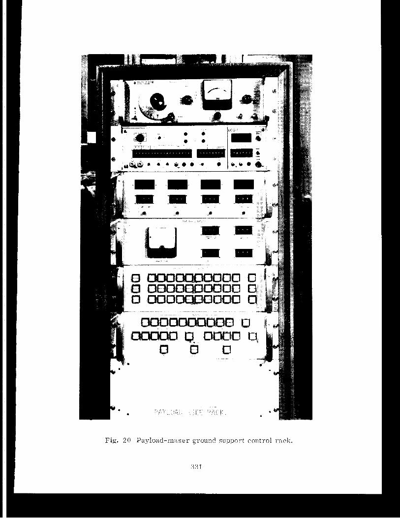
Figure 20 i s a photograph of t h e payload control rack . The
three funct ional groups within the rack a r e the Zeeman-frequency audio
o s c i l l a t o r , t h e c o n t r o l l e r group, and the quick-look telemetry group.
The magnetic f i e l d within the maser c a v i t y can be measured by applying
an audio-frequency f i e l d ac ross t h e c a v i t y s t r u c t u r e and observing t h e
frequency a t which t h e maser output leve l d ips (nominally between 500
and 1000 Hz) owing t o Zeeman t r a n s i t i o n s induced between the MF = - +1 and
0 subleve ls of t h e upper energy s t a t e of t h e hydrogen atom. The audio-
frequency source in the payload control rack i s a liewlett-Packard Model
651B audio o s c i l l a t o r . A p r i n t e d - c i r c u i t loop on the vacuum tank i s
wired t o t he o s c i l l a t o r o u t p u t through the u n ~ b i l i ca l cab le .
Payload Controls
The magnet ic- la tching r e l a y s i n t h e payload a r e con t ro l l ed by push-
button switches on t h e payload cont ro l rack , each switch con t ro l l i ng one
r e l ay in a t i n a r y sequence. The s i x s e t s of push-button c o n t r o l s com-
p r i s e t h r e e f o r t he magnetic f i e l d s , one f a r cav i ty tun ing , one f o r
hydrogen pressure , and one f o r source o s c i l l a t o r vo l tage .
The extremely simp1 e re1 ay-control c i r c u i t r y i s desiqned t o avoid
spurious r e l a y opera t ion caused by power f a i l ure o r e l e c t r o n i c ma1 func-
t i o n and t o provide nonvo la t i l e Inenlory between tinies when the payload i s
energized. Thc opera tor p re se t s t he des i r ed binary number i n t o push
but tons f o r a p a r t i c u l a r func t ion . A green ind ica to r lamp in t he bottom
half of each p re se t b u t t o n i nd i ca t e s which switches have been depressed;
no power can be appl ied t o t h e r e l ays a t t h i s po in t , Af te r t h e p re se t
number has been v e r i f i e d , t he opera tor momentarily depresses t h e s e t
switch t o apply power t o the r e l a y c o i l s , A red i n d i c a t o r lamp in the
top half of each p re se t switch s i g n a l s when t h e s e t cont ro l i s opera t ing
properly.
The r e l ays can be energized fro111 t h e power- supply on t he payload
control rack only i f t h e s e t switcn i s depressed; otnerwise, the r e l a y
c o i l s a r e cor~ipletely disconnected frorn the G S E E . Each r e l a y c o i l l i n e
i s brought out i nd iv idua l ly , through t h e unlbilical cab le , t o t h e cont ro l rack without involving t h e spacec ra f t e l e c t r o n i c s in any way; thus, no
malfunction aboard the spacec ra f t can a l t e r t h e s t a t e of t h e r e l a y s once
they a r e s e t from t h e GSEE payload cont ro l rack.
3 0 7
Quick-Look Telemetry
The control rack houses a Coded Communications Corp. Model ECO-1
PCM decoder, a d ig i t a l -d i sp lay uni t , and an analog-display uni t .
The decoder accepts the pay1 oad's PCM b i t stream and a 1000-bps
clock. Both s ignals a re provided by special balanced l i n e d r ive rs on
the maser payload and a r e routed through the umbilical cable t o balanced
l i n e receivers in the payload control rack and then t o the input of the
PCM decoder. The balanced signal l i ne s enhance the common-mode noise
re jec t ion of the quick-look telemetry system and a l so preserve the
ground i so la t ion of the payload e lect ronics . The output of the PCM
decoder i s a parall el &-b i t natural binary data word, a 6 -b i t para1 l e l
word ID, and a 3-bi t subframe ID. The decoder o u t p u t cycles through a l l
218 8 -b i t main-frame words in 1.024 sec; each word i s iden t i f i ed by the
appropriate word and subframe IDS.
The data b u s , the word ID b u s , and the subframe ID bus a re routed
t o the d ig i t a l -d i sp lay un i t . The system a l so provides f o r s e l ec t i ve
digi ta l - to-analog conversion on four channels f o r real- t ime monitoring
on s t r ip -char t recorders.
CONCLUSIONS
A t the time of writing t h i s paper, the data-reduction phase of the
experiment i s in f u l l swing. The reduction process consis ts of compar-
ing the frequency of the r e l a t i v i t y signal obtained from the system
shown in Figure 1 with predict ions of what t h i s signal frequency should
be from current ly accepted r e l a t i v i t y theory. The input data f o r the
predictions depend on tracking the posit ion and velocity of the probe t o
very high accuracy and deriving from these data the r e l a t i v i s t i c
frequency predict ions, including r edsh i f t , second-order doppler, and
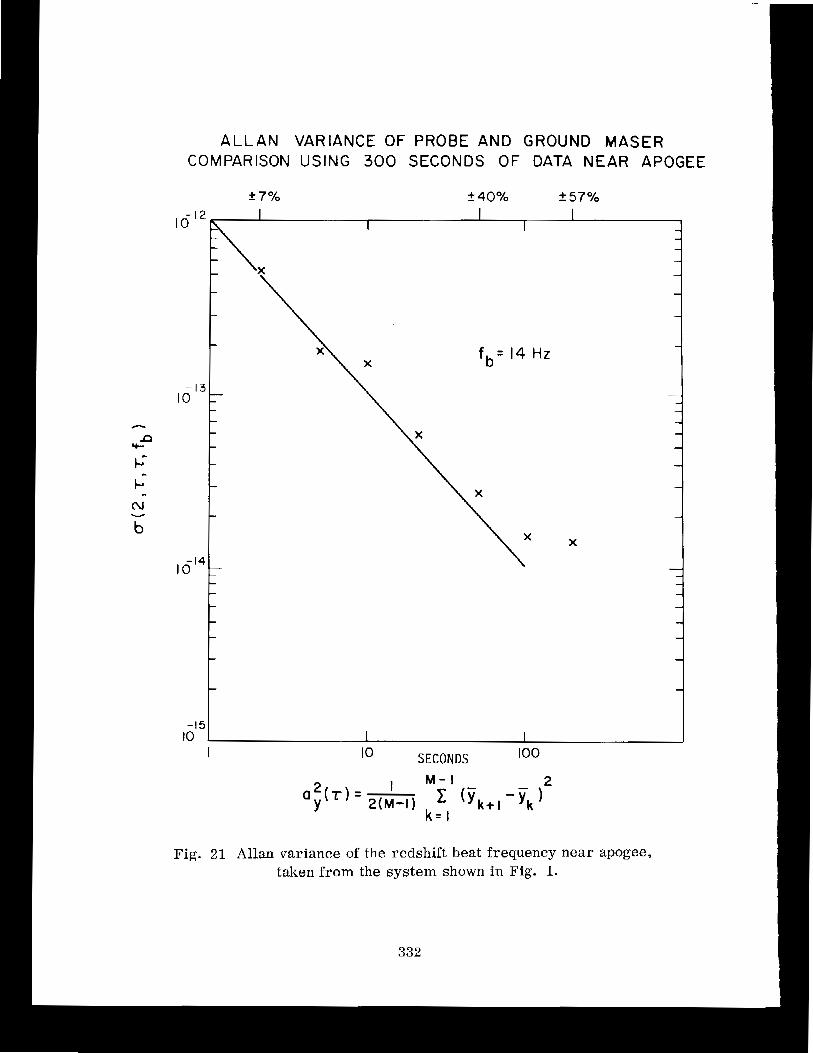
earth-motion e f f ec t s . From the data processing, s t i l l in progress, we
can recover the Allan variance o f t h e o~r tput da ta -taken a t maximum range,
shown in Figure 21 . These d a t a i ncl ude the e f f e c t s of rnore than 3000O km
of propagation and t h r e e passes through the e a r t h ' s atmosphere arid
ionosphere. These d a t a dre a u i t e s imi l a r 2:r: nlaser-comparison d a t a taken
i n t he labora tory over, a few rrieters o f c a h l e :
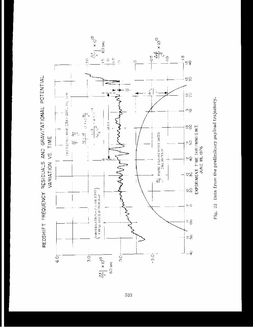
For t h e longer terrri d a t a t a k e n durinq , the ~ r i i s s i o n , Figure 2 2 shows
the res idua l frequency between observa t ion and p red ic t ions based on a
prel irninary t r a j e c t o r y deternii t i a t , i o n . The discrepancies near the ends
are s t i l l not understood i n d e t a i l ; however, in the present a n a l y s i s of
t h e t rackiny data used in determining the t ra . jector"y, t h e r e appears t o
be an i n c o r r e c t r e p r e s e n t a t i or) o f the pay1 odd ' s dyrtami c s d u r i n g t h e
f l i g h t , and a more complete co~riputation i s required t o obta in the probe's
t r a j e c t o r y . We look forward t o present ing a t o t a l ~ i c t u r e o f t he outcome
of t h i s experinlent i n the n e d t - f u t u r e .
A C K N O W L E D G M E N T
This work was supported -it1 pa r t by Coritrdct NA%-27969 f r v ~ ~ ~ the
National Aeronautics and Space Administrat ion.
REFERENCES
1 . R . F , C. Vessot a n d "1 v;. L e j i i r i e ( k ~ f ~ t * i r ; ; ~ t l c t . f:i;l.t:a (7 f S P ~ C . ~ arid
ground hydrogen m a s e r s arid ionospheri,; s ~ _ ~ l ( ? i e _ , ;::)r-, 1 - 1 . i l - l i i ~ C L U Y . ~ ~ : Y
comparisons between space c7tid L I I - O U ~ C I c loci , : . Is-. Proceeil-ir~gs -. o f the
28th Annual -- Frequerlcj i u n t r o l Syn-lpos"i un:, IJ . S .. k r ~ i ~ y f l ec1:ronics . -- -..
Command, F t . Monrriout~h, ?!.8.3., p p . 408-414, 1974.
2 . D . Kleppner, K , F . C . Vessot, and P i . l i a : - i . ~ s ~ ~ , The o r b i t i n g i fock
experirrlent t o deterrlii rle tile g r -av i t a t i o n a l v.edsi,iif t . fist.!-ophys.
Space S c i . , vo l . 6 , p p . ' 1 '3 -32 , 1970.
:3 09
3 . R . F . C . Vessot and M. W . Levine, Measurement of the gravitational
redshif t using a clock in an orbiting s a t e l l i t e . In Proceedings of
the Conference on Experimental Tests of Gravitation Theories, ed. by
R . W . Davies, J e t Propulsion Lab. Rep. 33-499, pp. 54-64, 1971.
4. R . F . C . Vessot, Lectures on frequency s t ab i l i t y a n d clocks and on the gravitational redshift experiment. In Experimental Gravitation,
ed. by B. Bertot t i , Academic Press, New York, pp. 111 -162, 1974.
5. S. Petty, R. Sydnor, and P . Dachel, Hydrogen maser frequency stand-
ards for the deep space network. I n Proceedings of the Eighth - Annual Precise Time a n d Time Interval Appl ications and Planning
Meeting, U.S. Naval Research Laboratory ( t h i s volume).
6 . M . W . Levine, R . F. C. Vessot, E . M . Mattison, E . Blomberg, T . E .
Hoffman, G. Nystrom, D. F . Graveline, R . L . Nicoll, C . Dovidio, and
W. Brymer, A hydrogen maser design for ground applications. I n
Proceedings of the Eighth Annual Precise Time and Time Interval
Applications and Planning Meeting, U.S. Naval Research Laboratory
( t h i s volume).
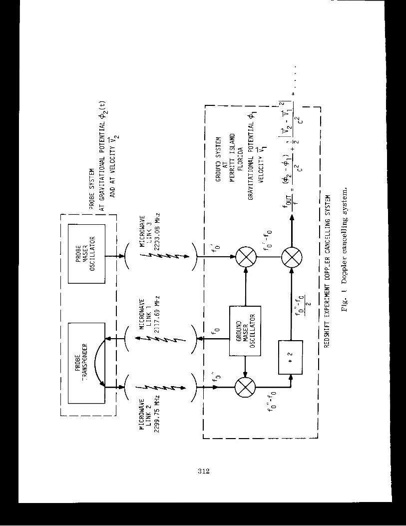
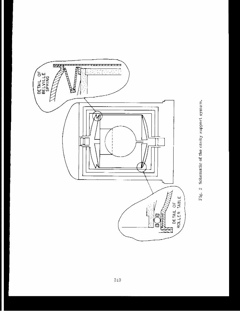
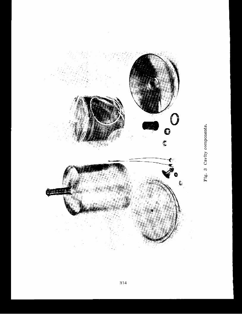
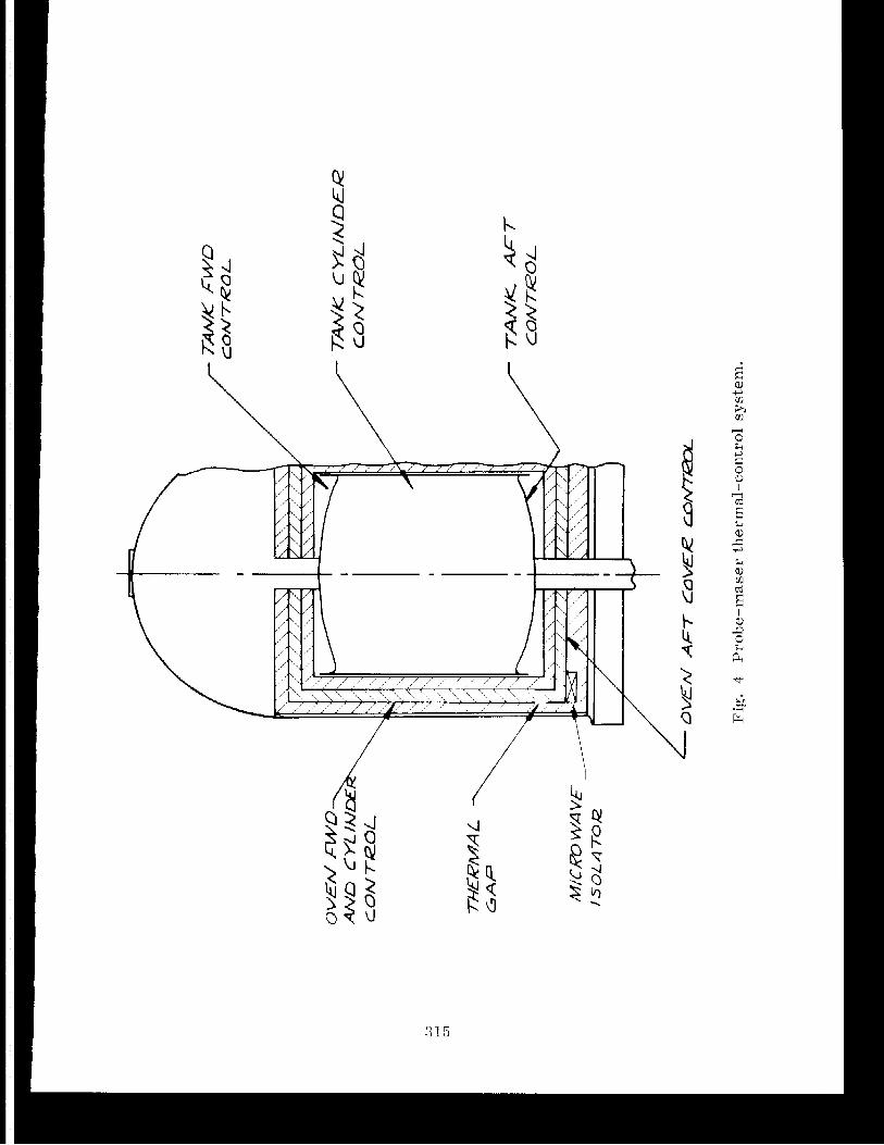
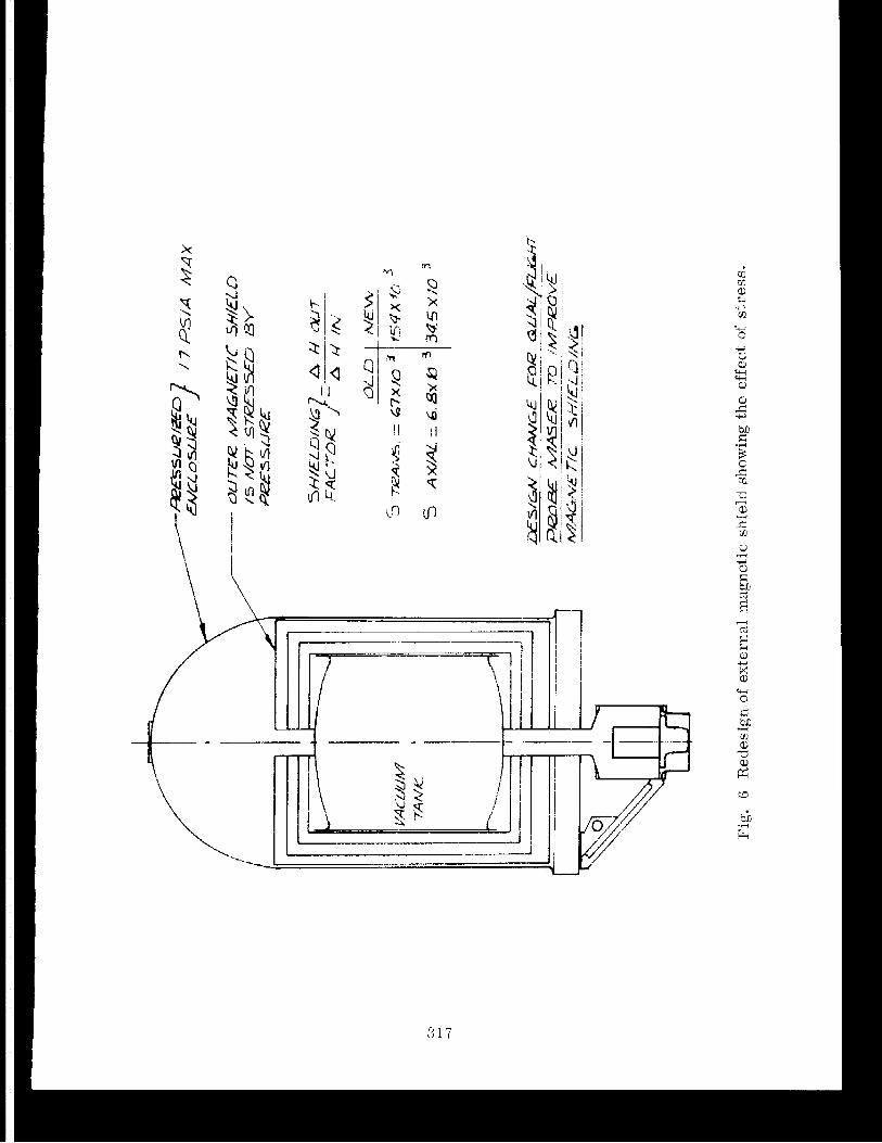
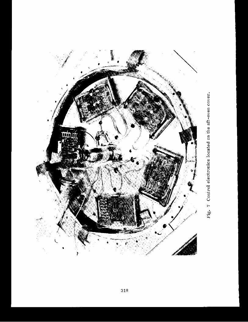
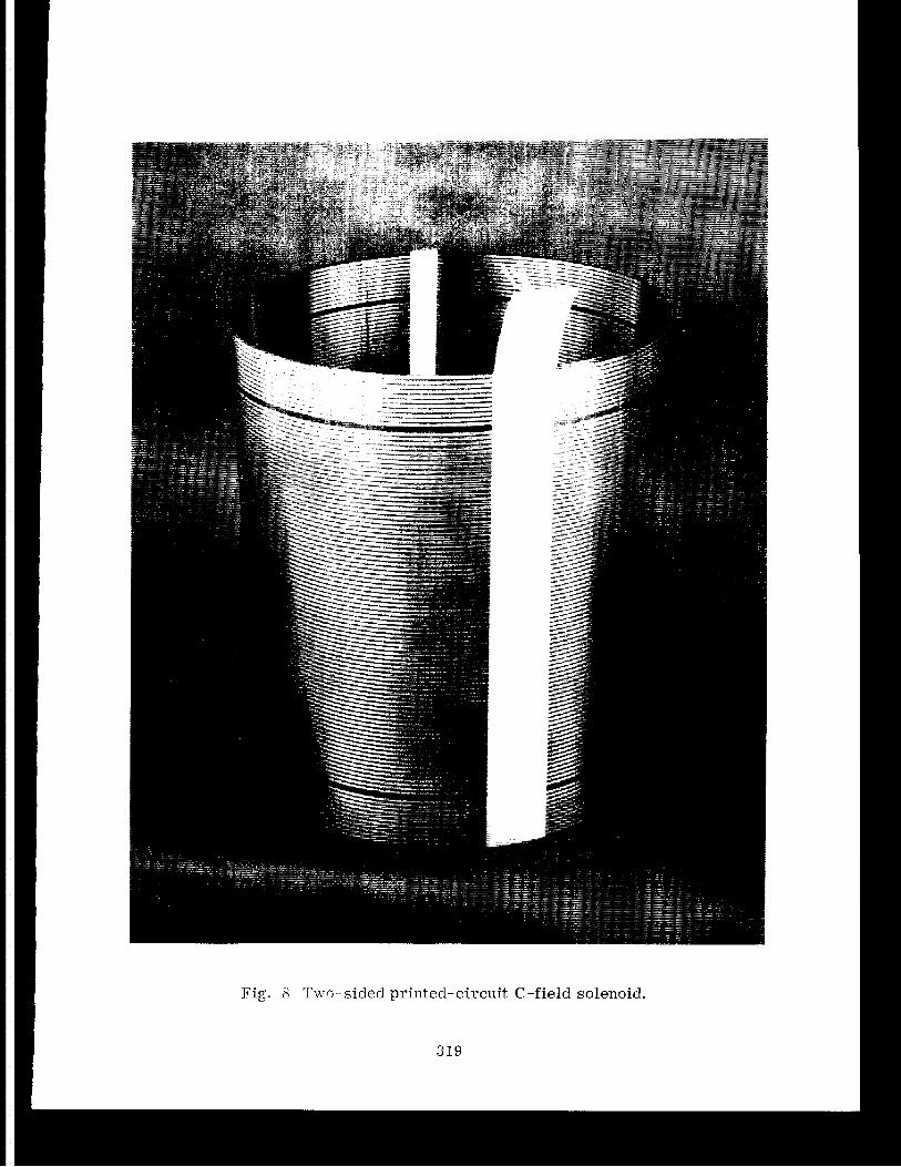
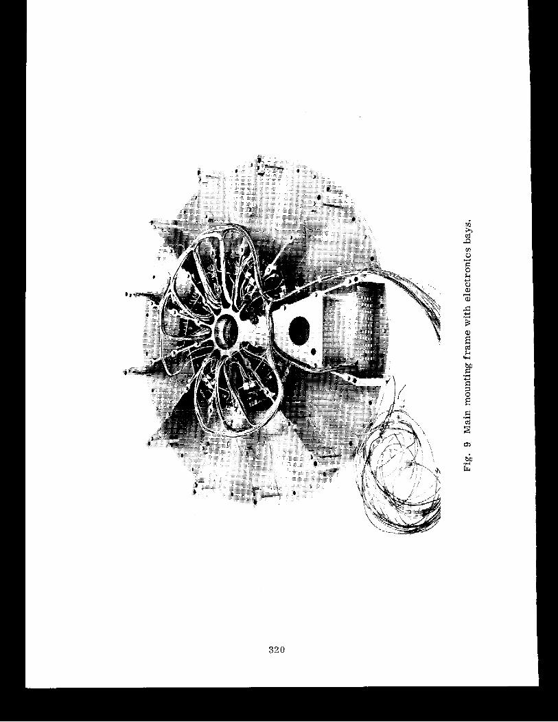
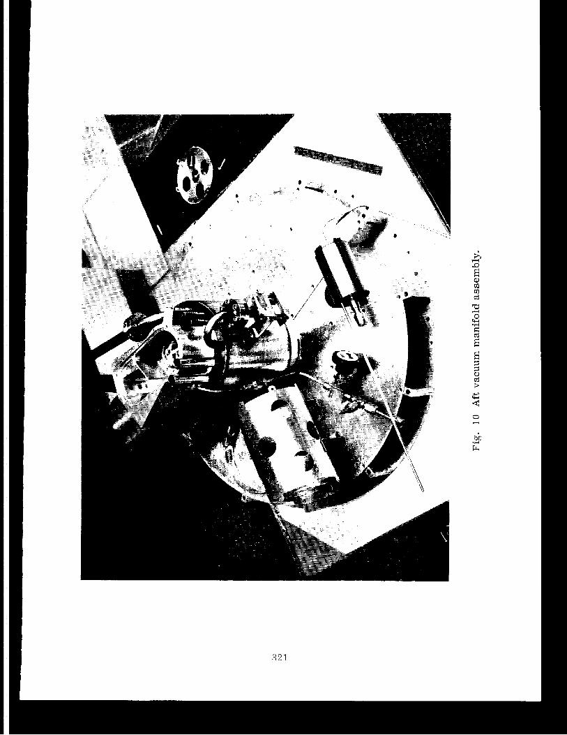
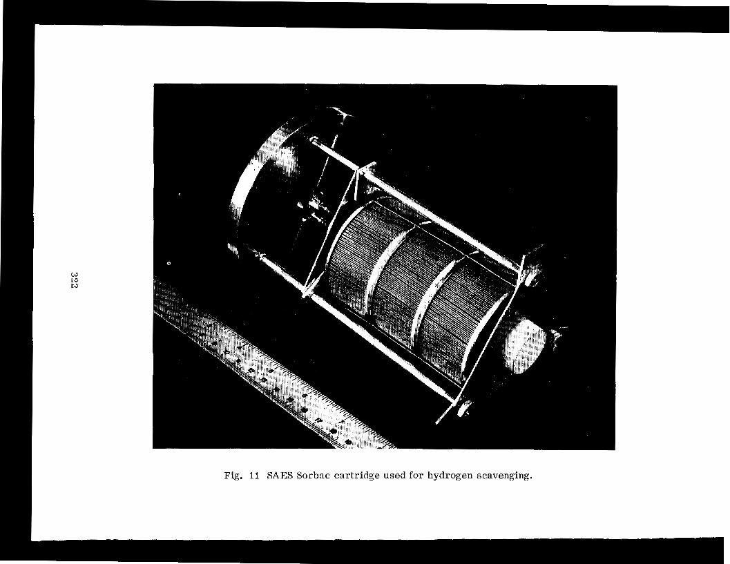
Fig. 11 SAES Sorbac car tr idge used for hydrogen scavenging.
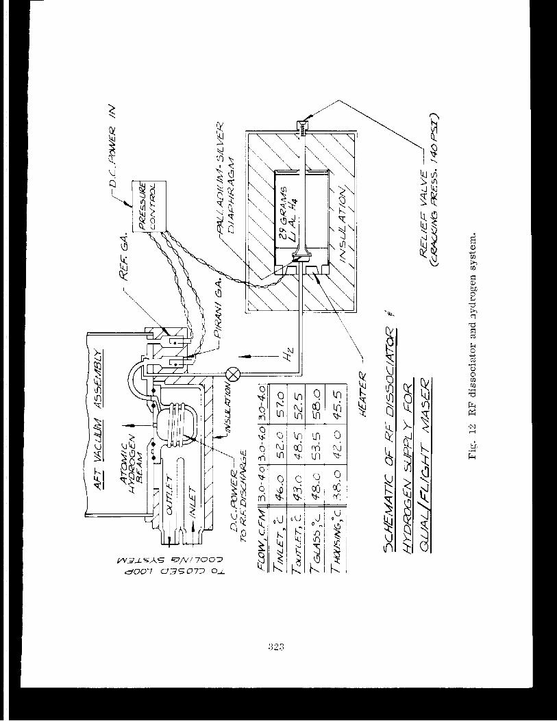
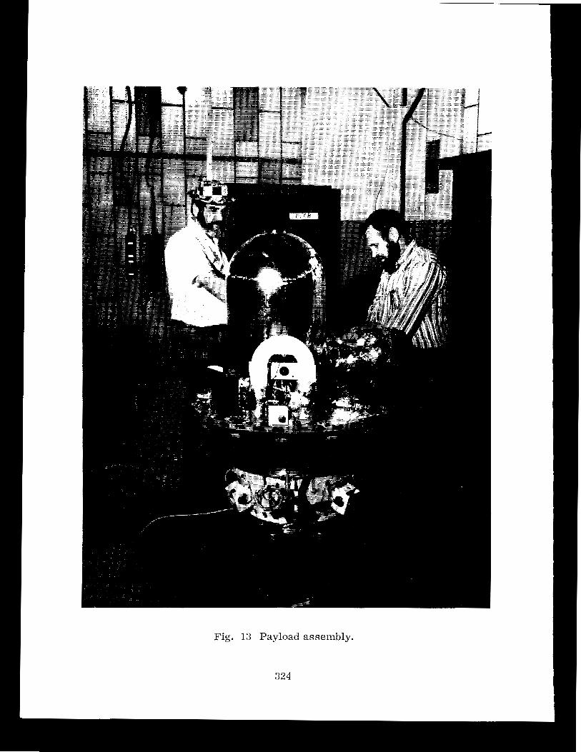
Fig. 13 Payload assembly.
' LO
----- - 1 :: iFt z O N e u
L - WLO 2 LO W 4
0 W
L N u - U CL a e m WLO r w 3 C L oa -
VARA
CTOR
DIO
DE
Ur
r
CAV
ITY
BASE
SHAD
ING
IND
ICAT
ES D
ESIG
N C
HANG
E
VACU
UM F
EEDT
HRU
GROU
NDIN
G TA
B
I I
""
'-----
--.
ASSY
A
2A22
AS
SY
A5A
5 AS
SY
A3A
5 M
IPLA
TE E
LEC
TRO
NIC
S AF
T O
VEN
COVE
R AF
T VA
CUUM
- +2
4V
COM
GRO
UND-
ISO
LATE
D VO
LTAG
E RE
FERE
NCE
FOR
DIO
DE
TUNE
R
Fig
. 17
C
avit
y e
lect
ron
ics
tuni
ng s
yst
em.
A L L A N VARIANCE OF PROBE AND GROUND M A S E R COMPARISON USING 300 SECONDS OF DATA NEAR APOGEE
I 10 SECONDS 100
Fig. 2 1 Allan variance of the redshift beat frequency near apogee, taken from the system shown in Fig. 1.