Embed Size (px)
Citation preview
Reprinted with permission from January 2015 QST ARRL, the national association for Amateur Radio® www.arrl.org
ing the center conductor switches the amplifier into transmit. There is also an AUX (auxiliary) phono jack that can be used to key a transceiv-er’s PTT input (more on this later). Most modern 432 MHz transceivers or
transverters should be able to key this amplifier.
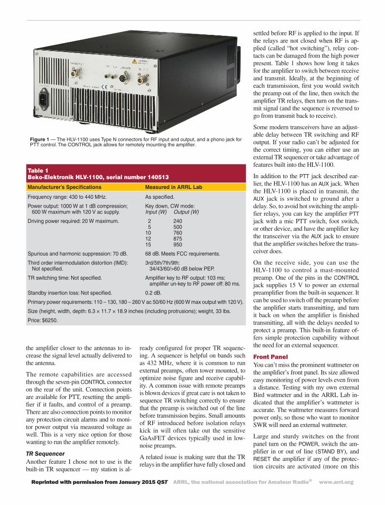
Once the 240 V and PTT lines are ready to go, all that remains is to hook up a coaxial jumper from the driver to supply RF input and another from the output of the amplifier to the antenna. Both the input and output use Type N female connectors. (You’ll need appropriate coaxial jumpers — standard RG-8 is only rated for about 500 W at this frequency.) There are two internal relays so that no additional relays are needed unless you use a mast mounted preamp. At my station, once I reached this point I was ready to go. From start to finish took a matter of minutes given the straight-forward steps for getting things set up.
Remote OperationThe HLV-1100 offers a couple of options that I did not take advantage of. First, the amplifier can be set up for remote operation if you like. Sometimes the heat generated by an amplifier is a concern, and remote operation keeps the shack cooler. More on this later, but I found the HLV-1100 to gen-erate the least amount of heat in any high-power amplifier I have run.
Another common reason to operate an am-plifier remotely on 432 MHz is to reduce feed line losses — they can be very high at this frequency if the run is long or the cable is not designed for use at UHF. I run low-loss 7⁄8-inch Andrew Heliax coaxial cable from my station to the antennas, so reducing losses was not a significant factor for my setup. Others may choose to move
Technical
by Mark Spencer, WA8SME
Beko-Elektronik HLV-1100 70 Centimeter Amplifier
A solid state kilowatt for our most popular UHF band.
Product Review
Mark J. Wilson, K1RO, [email protected]
Bottom LineThe Beko-Elektronik HLV-1100 is well
made and reliably provides 1000 W of clean RF on 70 centimeters for SSB, CW, WSJT, and other long-distance modes.
Reviewed by Jeff Klein, K1TEOQST Contributing [email protected]
A couple of years ago I was asked to do a QST Product Review of a high-power, solid state 144 MHz amplifier. It was a real eye-opener for someone used to running tube amplifiers with high voltage supplies and noisy fans, amplifiers that generate lots of heat in my shack. When asked to do another review of a high-power solid state amplifier, I jumped at the chance for another test drive.
This time the amplifier came from Beko-Elektronik, a German manufacturer that offers a lineup of VHF, UHF, and mi-crowave solid state amplifiers in several power ranges. This review focuses on the Beko HLV-1100 for 70 centimeters (430 – 440 MHz), a kilowatt-class amplifier that includes built-in power supply and transmit-receive (TR) relays. It’s basically a plug-and-play high-power amplifier for 70 centimeters that can be used with any of the popular transceivers or transverters delivering 20 W or so. The HLV-1100 uses MOSFET devices to generate the high power, and they run from an internal 50 V, 40 A dc power supply. Given all it con-tains, the unit weighs just 33 pounds and its dimensions are modest — 10.5 × 17.5 × 18.5 inches.
As a serious VHF/UHF DXer and contest operator, I have enjoyed running relatively high power on 432 MHz for many years. For the last 20 years or so, I have been using an old K2RIW designed amplifier sold by Arcos that was state-of-the-art 30 or more years ago. It uses a pair of 4CX250 tubes and continues to put out 500 W on the band reliably. The availability of
high-power, solid state amplifiers is still a relatively new option for UHF operators, offering an alternative to a variety of tube units that have been the only way to obtain QRO power levels in the past. I was very interested to see how my Arcos amp com-pared with a modern amplifier in operating capability and for convenience.
SetupThe HLV-1100 is essentially ready to go and similar to adding a linear amplifier to an HF station. The amplifier can be set up for either 240 V or 120 V operation. At the lower voltage level, the amp should run a maximum of 600 W output (per the instructions). At 240 V, it is capable of full output, and that’s how I set up the review unit. The power cord is detachable.
The amplifier has all TR relays built in, so the rest of the setup is easy. The rear panel (Figure 1) is very simple. There is a phono jack labeled PTT and simply ground-
Reprinted with permission from January 2015 QST ARRL, the national association for Amateur Radio® www.arrl.org
Table 1 Beko-Elektronik HLV-1100, serial number 140513
Manufacturer’s Specifications Measured in ARRL Lab
Frequency range: 430 to 440 MHz. As specified.
Power output: 1000 W at 1 dB compression; Key down, CW mode: 600 W maximum with 120 V ac supply. Input (W) Output (W)
Driving power required: 20 W maximum. 2 240 5 500 10 760 12 875 15 950
Spurious and harmonic suppression: 70 dB. 68 dB. Meets FCC requirements.
Third order intermodulation distortion (IMD): 3rd/5th/7th/9th: Not specified. 34/43/60/>60 dB below PEP.
TR switching time: Not specified. Amplifier key to RF output: 103 ms; amplifier un-key to RF power off: 80 ms.
Standby insertion loss: Not specified. 0.2 dB.
Primary power requirements: 110 – 130, 180 – 260 V ac 50/60 Hz (600 W max output with 120 V).
Size (height, width, depth: 6.3 × 11.7 × 18.9 inches (including protrusions); weight, 33 lbs.
Price: $6250.
the amplifier closer to the antennas to in-crease the signal level actually delivered to the antenna.
The remote capabilities are accessed through the seven-pin CONTROL connector on the rear of the unit. Connection points are available for PTT, resetting the ampli-fier if it faults, and control of a preamp. There are also connection points to monitor any protection circuit alarms and to moni-tor power output via measured voltage as well. This is a very nice option for those wanting to run the amplifier remotely.
TR SequencerAnother feature I chose not to use is the built-in TR sequencer — my station is al-
ready configured for proper TR sequenc-ing. A sequencer is helpful on bands such as 432 MHz, where it is common to run external preamps, often tower mounted, to optimize noise figure and receive capabil-ity. A common issue with remote preamps is blown devices if great care is not taken to sequence TR switching correctly to ensure that the preamp is switched out of the line before transmission begins. Small amounts of RF introduced before isolation relays kick in will often take out the sensitive GaAsFET devices typically used in low-noise preamps.
A related issue is making sure that the TR relays in the amplifier have fully closed and
settled before RF is applied to the input. If the relays are not closed when RF is ap-plied (called “hot switching”), relay con-tacts can be damaged from the high power present. Table 1 shows how long it takes for the amplifier to switch between receive and transmit. Ideally, at the beginning of each transmission, first you would switch the preamp out of the line, then switch the amplifier TR relays, then turn on the trans-mit signal (and the sequence is reversed to go from transmit back to receive).
Some modern transceivers have an adjust-able delay between TR switching and RF output. If your radio can’t be adjusted for the correct timing, you can either use an external TR sequencer or take advantage of features built into the HLV-1100.
In addition to the PTT jack described ear-lier, the HLV-1100 has an AUX jack. When the HLV-1100 is placed in transmit, the AUX jack is switched to ground after a delay. So, to avoid hot switching the ampli-fier relays, you can key the amplifier PTT jack with a mic PTT switch, foot switch, or other device, and have the amplifier key the transceiver via the AUX jack to ensure that the amplifier switches before the trans-ceiver does.
On the receive side, you can use the HLV-1100 to control a mast-mounted preamp. One of the pins in the CONTROL jack supplies 15 V to power an external preamplifier from the built-in sequencer. It can be used to switch off the preamp before the amplifier starts transmitting, and turn it back on when the amplifier is finished transmitting, all with the delays needed to protect a preamp. This built-in feature of-fers simple protection capability without the need for an external sequencer.
Front PanelYou can’t miss the prominent wattmeter on the amplifier’s front panel. Its size allowed easy monitoring of power levels even from a distance. Testing with my own external Bird wattmeter and in the ARRL Lab in-dicated that the amplifier’s wattmeter is accurate. The wattmeter measures forward power only, so those who want to monitor SWR will need an external wattmeter.
Large and sturdy switches on the front panel turn on the POWER, switch the am-plifier in or out of line (STAND BY), and RESET the amplifier if any of the protec-tion circuits are activated (more on this
Figure 1 — The HLV-1100 uses Type N connectors for RF input and output, and a phono jack for PTT control. The CONTROL jack allows for remotely mounting the amplifier.
Reprinted with permission from January 2015 QST ARRL, the national association for Amateur Radio® www.arrl.org
later). The final switch is PREAMP in or out that will power an amplifier through the sequencer. A nice feature is that the sequencer can be used even if the amplifier is in standby, allowing users to protect their preamplifiers. Each switch has an indicator light above to show status.
Amplifier Protection With expensive MOSFETs involved, it is important to know that the amplifier is likely to survive if problems are encoun-tered or mistakes are made. Red LEDs on the front panel light if any of the protection circuits are activated, placing the amplifier in standby. One is labeled ANTENNA and comes on for high SWR. That circuit will kick in at 1.8:1 or greater SWR to protect the MOSFETs. An OVERDRIVE indicator lights if input levels are exceeded, and a TEMPERATURE LED lights if the ampli-fier gets too warm and needs to move into standby mode. During my testing period, I did experience the OVERDRIVE protection activating. In addition to the LED light-ing, an audible alarm sounded and I easily heard its steady tone with headphones on. Pressing the RESET button on the front panel returns the amplifier to operation after a protection circuit trips.
For remote operation, voltage on one of the control jack pins can be monitored to deter-mine if there is a fault. Another pin can be grounded to reset the amp.
I used the amp for several months, and despite some significant continuous oper-ating in contests, I never triggered the tem-perature protection. Likewise, my antennas system withstood the high power levels and I did not set off SWR protection. The SWR protection is always helpful, especially at these power levels on 432 MHz where any slight issue in coax and antenna connection points can cause SWR spikes that can dam-age the amplifier. As detailed in the next section, I did activate the overdrive protec-tion and found that it triggered consistently as soon as I surpassed the threshold.
Conservative Overdrive ProtectionThe instructions indicate that the ampli-fier will provide approximately 17 dB of gain. While there are clear warnings that the MOSFETS will be damaged with more than 75 W of drive, maximum power out-put can be achieved with far less and the amplifier is specified at 20 W input.
During initial testing, I found that the over-
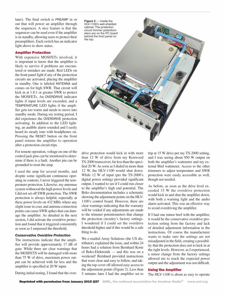
Figure 2 — Inside the HLV-1100’s well-shielded cabinet. The protection circuit trimmer potentiom-eters are on the PC board behind the front panel on the top.
drive protection would kick in with more than 12 W of drive from my Kenwood TS-2000 transceiver, far less than the speci-fied 20 W. As soon as I dialed in more than 12 W, the HLV-1100 would shut down. While 12 W of input (per the TS-2000’s digital power setting) provided significant output, I wanted to see if I could run closer to the amplifier’s high end potential. The Beko documentation includes a schematic showing the adjustment points on the HLV-1100’s control board. However, there are clear warnings indicating that the warranty will be voided if any adjustments are made to the trimmer potentiometers that change the protection circuitry’s factory settings. I wondered if I could set the overdrive threshold higher and if this would be a safe thing to do.
We e-mailed Array Solutions (the US dis-tributor), explained the issue, and within 24 hours had a solution from Bernhard Korte of Beko-Elektronik — and this was on a weekend! Bernhard provided instructions that were clear and easy to follow, and tak-ing the top cover off allowed easy access to the adjustment points (Figure 2). Less than 5 minutes later I had the amplifier set to
trip at 15 W drive per my TS-2000 setting, and I was seeing about 950 W output on both the amplifier’s wattmeter and my ex-ternal Bird wattmeter. Access to the other trimmers to adjust temperature and SWR protection were easily accessible as well, though not needed.
As before, as soon as the drive level ex-ceeded 15 W the overdrive protection would kick in and shut the amplifier down, with both a warning light and the audio alarm activated. This was an effective way to avoid overdriving the amplifier.
If I had one minor beef with the amplifier, it would be the conservative overdrive pro-tection setting from the factory and lack of detailed adjustment information in the instructions. Of course the manufacturer wants to make sure the settings are not misadjusted in the field, creating a possibil-ity that the protection does not to kick in at the right levels. However, as I experienced, a minor change from the factory settings allowed me to reach the expected power output and the adjustment was not difficult.
Using the AmplifierThe HLV-1100 is about as easy to operate
Reprinted with permission from January 2015 QST ARRL, the national association for Amateur Radio® www.arrl.org
See the Digital Edition of QST for a video overview of the Beko-Elektronik HLV-1100 70 Centimeter Amplifier.
as any amplifier I have ever used. Simply pushing the POWER switch allows for immediate operation — no waiting for a warm-up period.
The HLV-1100 is capable of running 1000 W or more output, and during the testing period I needed to be careful not to stress any other parts of my overall system. For example, I use a power divider to feed my four antennas, and it is rated at 1000 W, so I tried to keep the amplifier at 950 W to leave some margin and avoid creating any issues up on the tower.
Most of the time, when I used the amplifier, the only way to know it was powered on was to observe the green indicator light that showed it was powered up. My shack can be very noisy when all of my amps for the VHF, UHF, and microwave bands are on simulta-neously, as they are during contests. The HLV-1100 is a notable exception, as its cool-ing fans come on only when needed. During casual operation, they rarely engaged. Dur-ing extended continual operation, such as a 432 MHz sprint contest, the fans did kick in to cool the amplifier. The instructions say that they create minimal noise and that is an accurate description. Even with an hour straight of heavy-duty operation at nearly full output, the amplifier was barely warm to the touch. In summary, it was a pleasure to oper-ate with so little added noise and heat in my shack compared to my own 432 MHz tube amplifier.
During the review period, I operated mostly using CW and SSB modes. With consistent drive levels, output was the same in either mode. I did try the amplifier on digital modes as well to see how it performed, making several contacts using WSJT.
The instructions note in bold lettering that the unit is not to be operated at 100% duty cycle with full output. As a precaution, I backed the output down to 750 W while on digital, though I did not see any problems with the approximately one minute trans-mission cycle while using WSJT. Another warning in the manual cautions that the amplifier should not be used nonstop in transmit for more than 3 minutes. This was not an issue for my operating requirements but may be for those who would like to ragchew. For intense 432 MHz operating including contests, EME, and WSJT, the duty cycle should not be an issue.
On the VHF and UHF bands, during con-tests or band openings it’s common to be
High Power at UHFWhen considering a high-power amplifier for 70 centimeters or other UHF bands, it’s
important to evaluate the rest of your station. As noted in the review, all of the components following the amplifier must be able to handle the rated power (1000 W in this case) at 432 MHz.
Standard RG-8 or RG-213 is rated for only about 450 W at 400 MHz. Even the short in-terconnection cables in your station will need to be made from 3⁄8 or 1⁄2 inch hardline or one of the larger specialty cables such as the Times LMR series that can handle the power.
All coax connections need to be very solid. At these frequencies and power levels, you will definitely find the weak link in any coax connections — poor soldering, low-quality adapters, and so on. If you’re not careful, you will heat them up or melt them in no time. The amplifier uses Type N connectors because they can handle the power at this fre-quency and also have a constant impedance.
If you use an external preamp, check the ratings of any relays and be sure they provide adequate isolation to protect the preamp. Check the power rating of your antenna and of power dividers if you are using an array of several antennas.
This is also a good time to review RF exposure guidelines. Check out the many re-sources at www.arrl.org/rf-radiation-and-electromagnetic-field-safety.
listening for very weak signals with very loud local stations operating within a few kilohertz. Interference is minimized if everyone uses clean transmitters that are properly adjusted. I don’t want to cause anyone heartburn, so I ran a number of tests with nearby stations to determine how the unit sounded on the air. All reports were very complimentary and no issues were reported. Testing with locals comparing the driver only versus with the HLV-1100 in-line indicated no difference in signal qual-ity — exactly as it should be. As shown in Table 1, ARRL Lab testing indicates IMD products are suppressed 34 dB or more, better than the IMD products generated by transceivers.
SummaryHaving a chance to use the HLV-1100 for my 432 MHz operating for a few months was a terrific experience. Having kilowatt level power immediately available was great — more power than I have ever used on the band, and instant-on to catch those fleeting band openings. Having a quiet and
cool amplifier was a nice change of pace from the many tube amplifiers I have used in the past.
The HLV-1100 is attractive, easy to set up and use, and performs exactly as claimed. It was a lot of fun to get more than the usual number of “boy, you’re loud” comments while operating, and equally nice to have compliments about how great my signal sounded (credit here to the TS-2000 driver too).
Overall, this amplifier is an excellent ad-dition to any serious 432 MHz station whether for general, contest, EME, or digi-tal operating. It has a serious price tag, but all indications are that you will get what you paid for!
Manufacturer: BEKO-Elektronik, Am Längenmoosgraben 1a, D-85221 Dachau, Germany; www.beko-elektronik.de. Dis-tributed in the USA by Array Solutions, 2611 North Beltline Rd, Suite 109, Sunny-vale, TX 75182; www.arraysolutions.com.


![Hardinge HLV H Manual[1] Copy](https://img.pdfslide.us/doc/110x75/5466c90eb4af9f5d3f8b5517/hardinge-hlv-h-manual1-copy.jpg)