Embed Size (px)
Citation preview

8/3/2019 Marine Power Plant Chaprich
http://slidepdf.com/reader/full/marine-power-plant-chaprich 1/335

8/3/2019 Marine Power Plant Chaprich
http://slidepdf.com/reader/full/marine-power-plant-chaprich 2/335
GIFT OF
Alexander Dickey
ENGINEERING LIBRARY

8/3/2019 Marine Power Plant Chaprich
http://slidepdf.com/reader/full/marine-power-plant-chaprich 3/335

8/3/2019 Marine Power Plant Chaprich
http://slidepdf.com/reader/full/marine-power-plant-chaprich 4/335

8/3/2019 Marine Power Plant Chaprich
http://slidepdf.com/reader/full/marine-power-plant-chaprich 5/335
THE MARINEPOWER
PLANT

8/3/2019 Marine Power Plant Chaprich
http://slidepdf.com/reader/full/marine-power-plant-chaprich 6/335
PUBLISHERS OF BOOKS
Coal Age * Electric Railway Journal
Electrical World vEngineering News-Record
American Machinist *Ingenierfa Internacional
Engineering 3 Mining Journal * Powe r
Chemical $ Metallurgical Engineering
Electrical Merchandising

8/3/2019 Marine Power Plant Chaprich
http://slidepdf.com/reader/full/marine-power-plant-chaprich 7/335
THE MARINE POWER
PLANT
BY
LAWRENCE B. CHAPMANi
PROFESSOR OF NAVAL ARCHITECTURE, LEHIGH UNIVERSITY
FIRST EDITION
McGRAW-HILL BOOK COMPANY, INC.
NEW YORK: 370 SEVENTH AVENUE
LONDON: 6 & 8 BOUVERIE ST., E. C. 4
1922
8/3/2019 Marine Power Plant Chaprich
http://slidepdf.com/reader/full/marine-power-plant-chaprich 8/335

8/3/2019 Marine Power Plant Chaprich
http://slidepdf.com/reader/full/marine-power-plant-chaprich 9/335
PREFACE
The purpose of this book is to bring before the student the
thermodynamics of the marine power plant, the types of machinery
used for ship propulsion, and to give him a comprehensive idea
of the layout and function of the various pieces of auxiliary
machinery.
The book makes, no pretenses at being an exhaustive treatise.
It is intended as a first book in marine engineering. At Lehigh
University the study of the marine power plant as presented in
this book, is preceded by a course in thermodynamics and followed
by a summer at sea and by a more thorough and detailed study of
marine engines, turbines -and Diesel engines.
The thermodynamic and economic features of the power plant
have been accentuated throughout the book. Very little attention
has been given to mechanical details and all pure descriptive
matter has been reduced to a minimum. Details can be better
learned under actual operating conditions on shipboard than from
the inadequate treatment in a text book.
A short chapter on thermodynamics has been added as a review
for the engineering student and also as a foundation study for
others who may study the book. Complete calculations for the
sizes of the boilers and auxiliaries of a typical plant are given in
Chap. XIX. It is believed that this is the first time such cal-
culations have appeared in print.
A special feature of the book is the* comparison of the various
types of machinery used today for ship propulsion which is con-
cluded with a table showing an unbiased comparison of seven
types of propelling machinery.
While the book is intended primarily for the students of naval
architecture, marine engineering, and ship operation, it is believed
that it will bring before the sea going engineer and ship owner a
better understanding of the many types of propelling machinery
and auxiliaries used today.
L. B. CHAPMAN.
BETHLEHEM, PENN.,
June, 1922.

8/3/2019 Marine Power Plant Chaprich
http://slidepdf.com/reader/full/marine-power-plant-chaprich 10/335
ACKNOWLEDGMENT
The author wishes to thank the various manufacturers that
have kindly supplied illustrations. Acknowledgment is due to
James Howden Co. of America, Yarrow & Co., The Westinghouse
Mfg. & Elec. Co., The Babcock & Wilcox Co., The Foster Marine
Boiler Corp., Sulzer Bros, and the Busch-Sulzer Diesel Engine
Co., The Superheater Co., G. & J. Weir, The Bethlehem Ship-
building Corp., The Still Engine Co., The Griscom-Russell Co.,
The Schutte & Koerting Co., Sanford Riley Stoker Co., The
Underfeed Stoker Co. of America, The B. F. Sturtevant Co.,
Wallsend Slipway & Engineering Co., Cammell Laird Co., C. H.
Wheeler Mfg. Co., Worthington Pump & Machinery Corp.,
Charles Ward Engineering Works, The General Electric Co.,The DeLaval Steam Turbine Co., The William Cramp & Sons
Ship & Engine Building Co., The Wager Furnace Bridge Wall Co.,
for cuts and drawings; to The Society of Naval Architects and
Marine Engineers, The American Society of Naval Engineers and
The Institution of Naval Architects for permission to include
material from their transactions; to Marine Engineering and
Shipping Age for permission to publish Chap. VII and parts of
Chap. XIII and XIV previously published in that magazine;
and to McGraw-Hill Book Co. for permission to use certain cuts
from Sterling's Marine Engineers' Handbook.
L. B. CHAPMAN.

8/3/2019 Marine Power Plant Chaprich
http://slidepdf.com/reader/full/marine-power-plant-chaprich 11/335
CONTENTS
CHAP. PAGE
PREFACE^
v
I. Introduction 1i
II. Review of Thermodynamics of Steam 6
III. Fuels 26
IV. Marine Boilers 35
V. Combustion 68
VI. Draft 90
VII. Comparison of Oil and Coal for Steamships 103
VIII. Superheaters 110
IX. The Reciprocating Engine 115
X. The Steam Turbine 132
XI. The Geared Turbine and Combination Machinery 159
XII. The Electric Drive 174
XIII. The Diesel Engine 183
XIV. Comparison of Types of Propelling Machinery 211
XV. Condensers 230
XVI. Air Pumps 250
XVII. Feed Heaters 262
XVIII. The Power Plant Layout 271
XIX. Power Plant Computations 279
INDEX . 315
Vll

8/3/2019 Marine Power Plant Chaprich
http://slidepdf.com/reader/full/marine-power-plant-chaprich 12/335

8/3/2019 Marine Power Plant Chaprich
http://slidepdf.com/reader/full/marine-power-plant-chaprich 13/335
THE MARINE POWER PLANT
CHAPTER I
INTRODUCTION
1. Types of Machinery. In 1905 practically the only type of
machinery installation used on board merchant ships was the
reciprocating engine, and Scotch boiler in which coal was the
fuel universally used. In 1922, 16 years later, marine engineer-
ing is undergoing radical changes and is still in a state of flux.
Many new types of propelling machinery are in use and still
newer types are being strongly advocated. While the recipro-
cating engineand Scotch boiler are still used to a
large extent,the newer types are fast superseding this older type. Coal fuel
has practically been replaced by fuel oil.
Today we find the geared turbine and water-tube boiler used
almost as much as the reciprocating engine and Scotch boiler.
In addition, combination machinery, steam turbines, electric
drive, Diesel engines, and Diesel-electric drive are being widely
installed on many types of ships; and a combination type of
steam and Diesel engine, known as theStill
engine, is passingthe experimental stage.
With all these various types available for ship propulsion the
marine engineer and shipowner has a more interesting and
difficult task in deciding on the proper type of machinery than
was the case 16 years ago. All of these types will be fully treated
in the following pages and the advantages and disadvantages
of each type fully discussed.
2-
Comparison of Land and Marine Installations. The prob-lems confronting the designer of a marine power plant are far
more difficult than those confronting the designer of a power
plant on shore. The marine engineer and stationary engineer
have many problems bearing on efficiency, economy and costs
that are almost identical, and in many ways the power plant
1

8/3/2019 Marine Power Plant Chaprich
http://slidepdf.com/reader/full/marine-power-plant-chaprich 14/335
^2 THE MARINE POWER PLANT
on shipboard and on shore are much alike. The marine engi-
neer, however, has limitations of weight and space that are not
met by the engineer on shore.
For high speed ships it is vital, in order to reduce the resistance,
that the displacement be kept as small as possible. This neces-
sitates propelling machinery of light weight per horsepower.
The natural way to reduce the weight of machinery for a given
horsepower would be to increase the revolutions. High revo-
lutions of the propeller, however, are not compatible with good
propeller efficiency and high propeller efficiency is necessary in
order tokeep
thepower
of theship
at agiven speed
as low as
possible. Thus the designer is confronted at the outset with
two restricting conditions that conflict with each other.
While low steam and fuel consumption are just as important
on shore as on shipboard from the viewpoint of economy, the
marine engineer has additional incentives for low fuel consump-
tion besides cost of fuel. A reduction in the fuel consumption
of a ship's power' plant reduces the weight and space occupied
by fuel in the bunkers and consequently allows increased space
and weight for cargo which in turn results in a greater earning
capacity of the ship. If the steam consumption of the propel-
ling machinery can be reduced, the size and weight of boilers,
piping and main auxiliaries can be reduced with a further in-
crease in the earning capacity. The problem of power plant
design for a ship of high speed is far more difficult than that for
the slow speed cargo ship; yet there are many features such as
low propeller r.p.m., and space requirements that need careful
attention with the latter type.
The necessity for low steam consumption, light machinery
and low propeller revolutions have been the cause of the intro-
duction of fuel oil, light water-tube boilers, geared turbines and
electric drive. The low fuel consumption of the Diesel engine
has caused it to be adopted for low powered cargo ships, not-
withstandingits
greaterinitial cost and increased
weightover
steam machinery.
The average fuel consumption and weights of the various
types of machinery used today are given in the table on the
following page.
3. The Elementary Steam Power Plant. Practically all ma-
rine power plants are condensing as it is necessary to save the

8/3/2019 Marine Power Plant Chaprich
http://slidepdf.com/reader/full/marine-power-plant-chaprich 15/335
INTRODUCTION 3
condensed steam for feed water and surface condensers are used
entirely for ships navigating in salt water.
A diagrammatic layout of a simple plant is shown in Fig. 1.
The steam is generated in the boiler by absorbing heat from the
coal; the steam leaves the boiler with the heat contents x^i+qi
per pound and enters the engine or turbine through the throttle
valve. In the engine, mechanical work is done at the expense
of the heat in the steam. The heat left in the steam after expan-
TABLE I

8/3/2019 Marine Power Plant Chaprich
http://slidepdf.com/reader/full/marine-power-plant-chaprich 16/335
THE MARINE POWER PLANT
reduces the back pressure on the engine by means of the vacuum
produced by the condensed steam. This reduced back pressure
allows a greater expansion of the steam in the prime mover and
a larger amount of the heat in the steam is converted into
mechanical work. A complete diagram of a ship's power plant
showing all the auxiliaries, feed water heaters, etc., is shown in
Fig. 105.
Condensed Sfeam.
&o/ler

8/3/2019 Marine Power Plant Chaprich
http://slidepdf.com/reader/full/marine-power-plant-chaprich 17/335
INTRODUCTION 5
devoted to a large extent to the study of these losses and the
means adopted to increase this overall plant efficiency and
thereby reduce the fuel consumption.
The losses for the geared turbine and water-tube boiler are
roughly as follows:
Boiler losses: (boiler efficiency 75 per cent) Per Cent
Heat lost up stack 12.0
Incomplete combustion, moisture in fuel, etc 7.0
Radiation '6.0
Engine losses (friction, leakage, radiation) 2.0
Rejected to condenser cooling water 49.0
Pipe radiation and leakage (total plant) 1.0
Used by auxiliaries 18.0
Returned by auxiliary exhaust to feed water 9.0
Total net loss '85.0
In a Diesel engine installation, in which all the auxiliaries are
driven by the main engine, the losses are approximately as
follows:
Per Cent
Loss in jacket circulating water 10
Rejected in exhaust 30
Radiation and minor losses 1
Engine friction and auxiliary power 27
Total loss.. . 68

8/3/2019 Marine Power Plant Chaprich
http://slidepdf.com/reader/full/marine-power-plant-chaprich 18/335
CHAPTER II
REVIEW OF THERMODYNAMICS OF STEAM
It is assumed that the student has made a study of the thermo-
dynamics of the steam and gas engine and is familiar with the
use of the steam tables and diagrams. The following chapter
has been prepared as a brief review of the more important fea-tures of thermodynamics that are necessary for a study of the
marine power plant. The thermodynamics of the steam turbine
is given full treatment in Chap. X.
5. The Generation of Steam. For engineering purposes steam
is generated by the combustion of coal or fuel oil. The feed water
is injected into the boiler at some temperature above 32F. 1 The
heat contained in this water above 32 is expressed in b.t.u.'s per
Ib. by the symbol g2 - The water in the boiler now absorbs heat
produced by the combustion of the fuel and its temperature
rises until it reaches the boiling point at some predetermined
pressure. The heat in this water in the boiler expressed in b.t.u.'s
per Ib. above 32F. is q\ (the heat of the liquid). The heat added
to the water thus becomes (#1 #2) b.t.u. per pound.
In order to understand clearly the phenomenon that is taking
place in the boiler and the application of the steam tables, it is
convenient to assume that the water in the boiler is under an
initial air pressure of P\ Ibs. per sq. in. As steam begins to form
in the boiler first the air and then the steam is drawn off at the
same rate as the steam is generated. Thus the pressure in the
boiler is always constant.
As further heat is added to the water which has already
reached the boiling temperature, the water begins to boil at a
constant temperature corresponding to the pressure PI and steamis formed. The heat absorbed in changing a pound of water at
the boiling point into steam is known as the heat of vaporiza-
tion and is expressed by the symbol r\. If the boiling takes
JThe steam tables are based for convenience on the heat contents above
32F. in other words water at 32 is assumed to have zero heat contents.
6
8/3/2019 Marine Power Plant Chaprich
http://slidepdf.com/reader/full/marine-power-plant-chaprich 19/335
THERMODYNAMICS OF STEAM 7
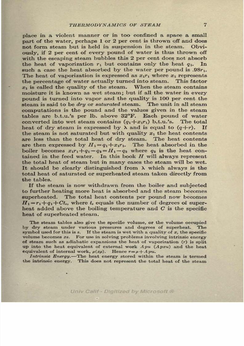
place in a violent manner or in too confined a space a small
part of the water, perhaps 1 or 2 per cent is thrown off and does
not form steam but is held in suspension in the steam. Obvi-
ously, if 2 per cent of every pound of water is thus thrown off
with the escaping steam bubbles this 2 per cent does not absorb
the heat of vaporization TI but contains only the heat<?i. In
such a case the heat absorbed by the water per pound is .98fi.
The heat of vaporization is expressed as x^i where Xi represents
the percentage of water actually turned into steam. This factor
x\ is called the quality of the steam. When the steam contains
moisture it is known as wet steam; but if all the water in every
pound is turned into vapor and the quality is 100 per cent the
steam is said to be dry or saturated steam. The unit in all steam
computations is the pound and the values given in the steam
tables are b.t.u.'s per Ib. above 32F. Each pound of water
converted into wet steam contains (qi+xtfi) b.t.u.'s. The total
heat of dry steam is expressed by X and is equal to (<?-f-r). If
the steam is not saturated but with quality Xi the heat contents
are less than the total heat of dry steam. The heat contents
are then expressed by Hi = qi+xiri. The heat absorbed in the
boiler becomes Xiri+qi q2= Hi q2 where q* is the heat con-
tained in the feed water. In this book H will always represent
the total heat of steam but in many cases the steam will be wet.
It should be clearly distinguished from X which always is the
total heat of saturated or superheated steam taken directly from
the tables.
If the steam is now withdrawn from the boiler and subjected
to further heating more heat is absorbed and the steam becomes
superheated. The total heat contents per pound now becomes
Hi=ri+qi+Ct8 ,where ts equals the number of degrees of super-
heat added above the boiling temperature and C is the specific
heat of superheated steam.
The steam tables also give the specific volume, or the volume occupied
by dry steam under various pressures and degrees of superheat. Thesymbol used for this is s. If the steam is wet with a quality of x, the specific
volume becomes xs. For use in solving problems involving intrinsic energy
of steam such as adiabatic expansions the heat of vaporization (r) is split
up into the heat equivalent of external work Apu (Apxu) and the heat
equivalent of internal work, p(xp). Hence r=p+Apu.Intrinsic Energy. The heat energy stored within the steam is termed
the intrinsic energy. This does not represent the total heat of the steam

8/3/2019 Marine Power Plant Chaprich
http://slidepdf.com/reader/full/marine-power-plant-chaprich 20/335
8 THE MARINE POWER PLANT
(xr+q) because during the process of vaporization and the accompanying
increase in volume some of the heat energy was used in doing external work
in pushing back the surrounding media and this portion of the energy Apu
is considered as stored in the surrounding media. The intrinsic energy ofsteam thus becomes x\r\ ApiXiu
=Xipi+qi or expressed in ft. Ibs.,
E l/A (x\pi -f- gi) where A is the reciprocal of the mechanical equivalent
of heat, p is the pressure of the steam and u is the increase in volume of
one pound of water in passing from water into steam. 1
6. Entropy. Entropy is a valuable property of steam and is
useful in solving many problems in steam engineering. All our
work with this property is limited to changes in entropy rather
than with the absolute amount. If d$ represents an infinitesimal
change in entropy, we can define this change in entropy as
d<f>= dQ/T where dQ represents an infinitesimal change in the
heat contents and T the constant absolute temperature at which
this change takes place. Therefore, the common definition of
entropy becomes,
As just pointed out all our study with entropy applies to
changes in entropy; yet we are accustomed to speak of total
entropy meaning thereby the entropy change above 32F.
An adiabatic change of gas or vapor is one under such con-
ditions of insulation that no energy, in the form of heat is given
up nor none received during the change. Thus for a reversible
adiabatic, dQ = and from our definition of change in entropy
given above,01-02 =
We can thus make the important statement that during a revers-
ible adiabatic change (expansion or compression) there is no
change in entropy.
A convenient way of thinking of entropy in the early stages
and securing some tangible grasp of its significance, is to consider
entropy that property of steam which is constant during a revers-
ible adiabatic expansion, in a similar way in which temperature
(a familiar property) is constant during an isothermal expansion.
This of course is not a true and complete definition of entropy
but one often found helpful in the early study of thermodynamics.
*For a full explanation of the above the student is referred to Hirshfeld
and Barnard's "Elements of Heat Power Engineering," Chap. II.
8/3/2019 Marine Power Plant Chaprich
http://slidepdf.com/reader/full/marine-power-plant-chaprich 21/335
THERMODYNAMICS OF STEAM
A true understanding and familiarity with entropy can only be
acquired by the solution of problems involving its application.
The steam tables give values of 6 entropy of the liquid, and
r/T, entropy of vaporization. The total entropy of the steam
is, . The total entropy cf superheated steam can also
be found from the steam tables.
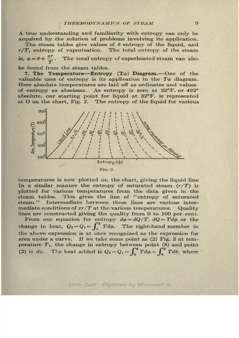
7. The Temperature Entropy (T<) Diagram. One of the
valuable uses of entropy is its application in the T<f> diagram.
Here absolute temperatures are laid off as ordinates and values
of entropy as abscissas. As entropy is zero at 32F. or 492
absolute, our starting point for liquid at 32F. is represented
at O on the chart, Fig. 2. The entropy of the liquid for various
90
I 700-
o[
600H
500- \
Entropy (<)
temperatures is now plotted on the chart, giving the liquid line
In a similar manner the entropy of saturated steam (r/T) is
plotted for various temperatures from the data given in the
steam tables. This gives the line of "entropy of saturated
steam." Intermediate between these lines are various inter-
mediate conditions of xr/T at the various temperatures. Quality
lines are constructed giving the quality from to 100 per cent.
From our equation for entropy d<j>= dQ/T, dQ = Td<f> or the
/*2
change in heat, Qz Qi = J 1Tdfy. The right-hand member in
the above expression is at once recognized as the expression for
area under a curve. If we take some point as (2) Fig. 3 at tem-
perature T7
!,the change in entropy between point (8) and point
(2) is d$. The heat added is Q*-Qi =*
Td<j>=
*
Td6, where

8/3/2019 Marine Power Plant Chaprich
http://slidepdf.com/reader/full/marine-power-plant-chaprich 22/335
10 THE MARINE POWER PLANT
6 = entropy of the liquid. This expression is represented by the
area 9-2-8-5 in Fig. 3. Therefore the area on the T$ diagram
represents heat change as in a similar way the area on the PV
diagram represents work. This area 9-2-8-5 must extend down
to absolute zero for it is represented by JTdd where T is abso-
lute temperature and dd is the change entropy.
Obviously, area 0-1-8-5 representing I TdO must represent/o
the heat of the liquid q. Likewise area 8-3-4-5= (r/TXT) =r
represents the heat of vaporization. Area 0-1-8-3-4 represents
the total heat(<?+r).
If the steam is notentirely dry
and sat-
urated r becomes xr and r/T becomes xr/T. The area 8-6-7-5
represents xr under these conditions.
T,
492f.
T
8
95
FIG. 3.
8. Mollier Diagram. Another very useful diagram is the
Mollier or H(j> diagram. The data from the steam tables is
plotted on this chart with total heat contents as ordinates and
total entropy as abscissas. Lines of quality and superheat (which
is quality above the saturated condition) and steam pressures
are plotted on the Mollier diagram. Thus the total heat con-
tentsand
totalentropy
for
anycondition of
steam pressure,
quality or superheat can be read off this chart at once, although
not with the same degree of accuracy as in the tables.
9. Adiabatic Expansion. As already mentioned (Article 6),
an adiabatic expansion or compression of steam or gas is one
in which there is no heat received or given off to the surrounding
media; during a reversible adiabatic change, entropy is constant.

8/3/2019 Marine Power Plant Chaprich
http://slidepdf.com/reader/full/marine-power-plant-chaprich 23/335
THERMODYNAMICS OF STEAM 11
The most common reversible adiabatic expansion is the expan-
sion of steam in the cylinder of an ideal reciprocating steam
engine.
In Fig. 4, if dry steam at pressure PI corresponding to tempera-
ture TI is expanded adiabatically to pressure P2 corresponding
to temperature !T2 ,it will be represented on the T<j> diagram
by a vertical line extending downward from point 1 on the dry
steam line. Entropy is constant and the temperature is
reduced, therefore the adiabatic expansion is represented by the
vertical line 1-2. At condition 1 the steam was dry but as it
expands at constant entropy the steam becomes wet. This is
clearly shown in Fig. 4 where the line 1-2 cuts lines of lower and
f
FIG. 4.
lower quality in its expansion to P2 . Thus at P2 the quality
is x2 .
An example will make this clear: Suppose one pound of dry
steam at 275 Ibs./sq.in. absolute (410F.) were expanded adia-
batically to 6 Ibs./sq.in. absolute (170F.). Noting the initial
condition on Peabody's T(f> diagram, we have 0i= 1.52 ^ = 410
i
= 1.00. As the entropy does not change $i =< 2 = 1.52 and
runningdown along the line <= 1 .52 to tz
= 170 we have x2= .805.
The same results can be obtained from the Mollier diagram by
looking up the intersection of the 275 Ibs. line with the saturated
steam line. The entropy is found to be 1.52 and running down
the line = 1.52 until it intersects the 6 Ib. pressure line, 2
equals .805 as before.

8/3/2019 Marine Power Plant Chaprich
http://slidepdf.com/reader/full/marine-power-plant-chaprich 24/335
12 THE MARINE POWER PLANT
The quality after the expansion can also be found by equating
the entropy expressions for conditions PI and P2 .
Here, b ri/Ti, 2 and r2/77
2 can be looked up in the steam
tables and z2 the only unknown obtained.
6,= .5771 62
= .2476
rj/77
!= .9429 r2/!F2
= 1.5812
2 = 1.52 = .2476+1.582x2
^21.2724
10. Constant Heat Change. Another expansion of great im-
portance in steam engineering is a change in pressure without
any change in heat contents. This, obviously, is an adiabatic
change but it is an irreversible process and its entropy is not
constant as in the reversible adiabatic just studied. No me-
chanical work is done during this change.
The two most common occurrences of this expansion are
when steam is reduced in pressure by a reducing valve and in
the "wiredrawing" through the valves and passages of an
engine or turbine. In both these cases the reduction in pressure
is accompanied by an increase in velocity of the steam, but as
the steam is brought more or less to rest after the reduction
in pressure the heat given up to cause the velocity is returnedto the steam by impact and friction.
This change can best be studied by means of the Mollier
diagram. Suppose steam at 200 Ibs. absolute pressure at 98
per cent quality is reduced in pressure through a reducing
valve to a pressure of 35 Ibs. absolute. Turning to the Mollier
diagram we find at the intersection of the 200 Ibs. line and the
.98 quality line the total heat contents of one pound of steam
= 1,180 b.t.u. and the total entropy = 1.525. As this is a re-
duction in pressure (expansion) without any change in heat
contents, we follow across the heat contents line of 1,180 b.t.u.
until it crosses the line of 35 Ibs. pressure (interpolate between
30 and 40 Ibs.). The quality is now 30 superheat in
other words the wet steam has become superheated during the
reduction in pressure. This should naturally follow for a

8/3/2019 Marine Power Plant Chaprich
http://slidepdf.com/reader/full/marine-power-plant-chaprich 25/335
THERMODYNAMICS OF STEAM 13
constant heat change, as some of the heat of the liquid (q) at
200 Ibs. has now been converted into superheat at the reduced
pressure of 35 Ibs. where qz is smaller. (See values of qi qz r\
and r2 in tables.) During this reduction in pressure the entropy
has increased from 1.525 to 1.707. While this expansion is
adiabatic it is not isentropic.
This reduction in pressure without any loss in heat contents
is the principle on which Prof. Peabody's throttling calorimeter
for measuring the quality of steam, is based. Wet steam at
a known pressure and unknown quality is expanded through'a
partly closed valve until it is superheated. The temperature
and pressure after throttling of the steam can be read and its
heat contents computed. The heat contents before and after
throttling are of course the same, and x\ can therefore be found.
11. The Rankine Cycle with Complete Expansion(Clausius).
This cycle is generally spoken of as the cycle of the ideal engine
or more commonly as the Rankine cycle. Some writers refer to
it
as the Clausius cycle reserving the word Rankineto the
cycle with incomplete expansion. In this book it will be re-
ferred to as the Rankine cycle. The pressure volume (PV)
diagram of this theoretical cycle is represented in Fig. 5 and
the T(j> diagram in Fig. 6. It consists of a constant pressure
(Pi) admission from the boiler along ab; cut off from the
boiler at b; adiabatic expansion from 6 to c at back pressure
8/3/2019 Marine Power Plant Chaprich
http://slidepdf.com/reader/full/marine-power-plant-chaprich 26/335
14 THE MARINE POWER PLANT
\
P2 ;exhaust to the condenser along cd; and constant volume
compression along da to the initial pressure PI.
The cycle should not be thought of as taking place in an engine
cylinder but in a plant, consisting of boiler, engine, condenser
and necessary pumps in other words it is in its broadest sense
a plant cycle.
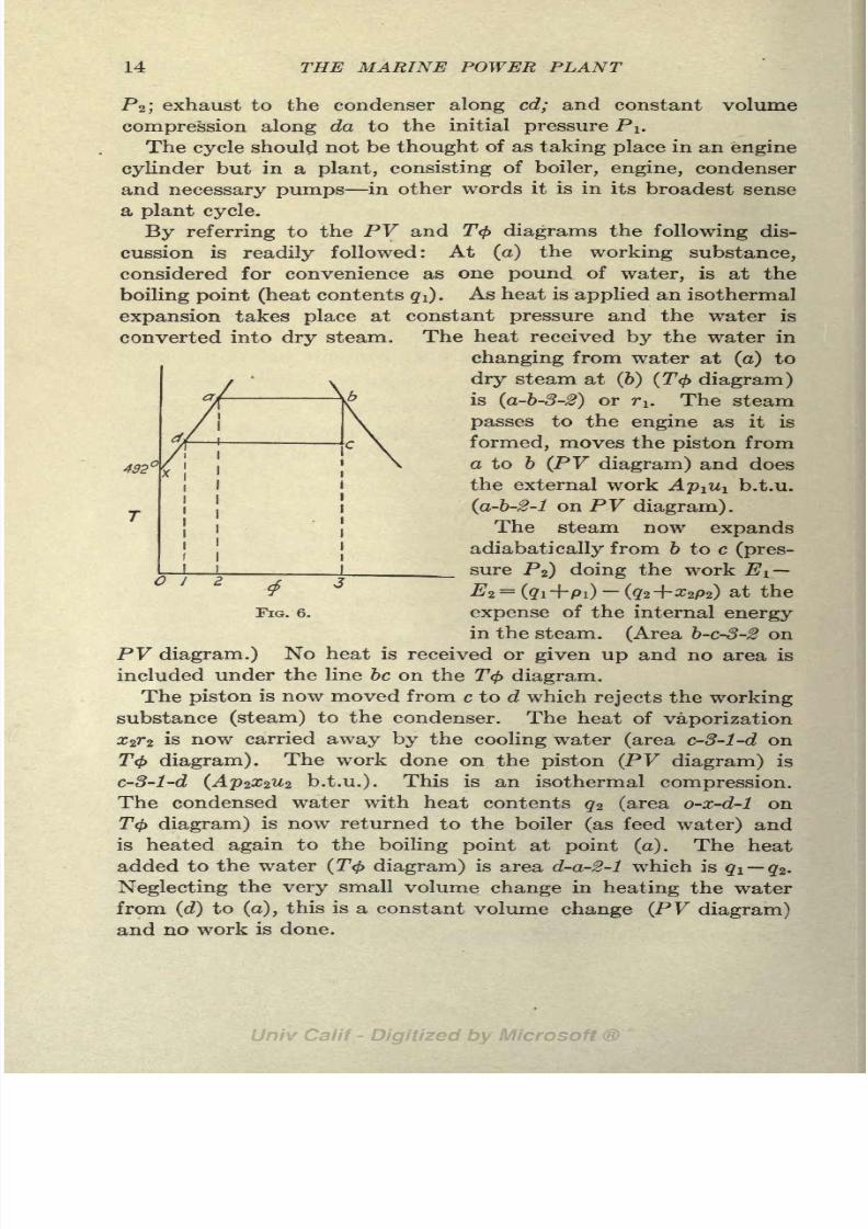
By referring to the PV and T<f> diagrams the following dis-
cussion is readily followed: At (a) the working substance,
considered for convenience as one pound of water, is at the
boiling point (heat contents #1). As heat is applied an isothermal
expansion takes place at constant pressure and the wateris
converted into dry steam. The heat received by the water in
changing from water at (a) to
dry steam at (b) (T<}> diagram)
is (a-b-3-2) or TI. The steam
passes to the engine as it is
formed, moves the piston from
432^\ a to b (PV diagram) and does
the external work Aplul b.t.u.
(a-b-2-1 on PV diagram).
The steam now expands
adiabatically from b to c (pres-
sure P2) doing the work E L
FIG. 6. expense of the internal energy
in the steam. (Area b-c-3-2 on
PV diagram.) No heat is received or given up and no area is
included under the line be on the T<f> diagram.
The piston is now moved from c to d which rejects the working
substance (steam) to the condenser. The heat of vaporization
#27*2 is now carried away by the cooling water (area c-3-l-d on
T$ diagram). The work done on the piston (PV diagram) is
c-3-l-d (Ap2xzU2 b.t.u.). This is an isothermal compression.
The condensed water with heat contents qz (area o-x-d-1 onT<f> diagram) is now returned to the boiler (as feed water) and
is heated again to the boiling point at point (a). The heat
added to the water (T<f> diagram) is area d-a-2-1 which is qi qz.
Neglecting the very small volume change in heating the water
from (d) to (a), this is a constant volume change (PV diagram)
and no work is done.
I

8/3/2019 Marine Power Plant Chaprich
http://slidepdf.com/reader/full/marine-power-plant-chaprich 27/335
THERMODYNAMICS OF STEAM 15
Collecting our terms, we have the work done during the cycle
from the PV diagram is W =(a-b-2-l) + (b-c-3-2)-(c-3-l-d)
=
area abed. From the thermodynamic standpoint we have:
=qi+ T 1 #2 227*2
=H\ H2
where
AP&I+ pi=
ri
and
Ap2x2u2 -{- x2p2
= X2r2
u\ the increase in volume during vaporization.
X2u2= decrease in volume during condensation.
From the T0 diagram the heat received is
and the heat rejected is
The work done becomes
Qi Q2 = ri+qi q2
This is the same expression as found from the PV diagram.
The efficiency of the cycle becomes
_,- output work done HiH2iLn .
=-;-
7-=
,-
:-
:
-7= VT-
input heat received HI q2
In this book,
Qi = heat received.
Q2= heat rejected.
X = total heat of steam from tables.
#i = heat contents for condition 1 (=
iri-f #1)
H2= heat contents for condition 2 (
= x2r2+q2)
The above method of explaining the Rankine cycle is not the
one used in treatises onthermodynamics
but is a most instructive
one for the student who has been through a regular course in
thermodynamics and is familiar with the customary presentation
of cycles.
This is the standard cycle used as a basis of comparison for
all types of steam engines and turbines and the above efficiency
will be used constantly in this book.
8/3/2019 Marine Power Plant Chaprich
http://slidepdf.com/reader/full/marine-power-plant-chaprich 28/335
16 THE MARINE POWER PLANT
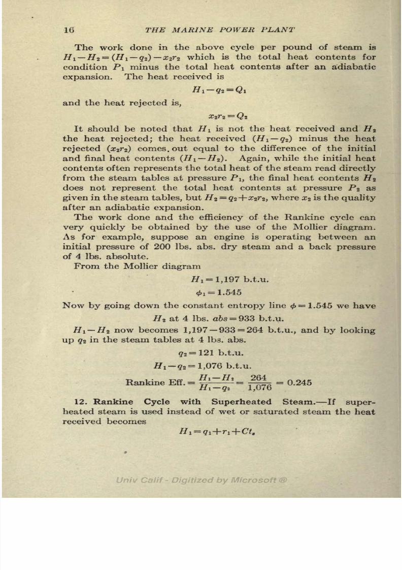
The work done in the above cycle per pound of steam is
Hi Hz = (Hi qz)X2rz which is the total heat contents for
condition PI minus the total heat contents after an adiabatic
expansion. The heat received is
H l -qz = Q l
and the heat rejected is,
It should be noted that HI is not the heat received and H z
the heat rejected; the heat received (Hi q2) minus the heat
rejected (z2r2) comes, out equal to the difference of the initial
and final heat contents (Hi Hz). Again, while the initial heat
contents often represents the total heat of the steam read directly
from the steam tables at pressure PI, the final heat contents HZ
does not represent the total heat contents at pressure P2 as
given in the steam tables, but Hz^qz+xtfz, where Xz is the quality
after an adiabatic expansion.
The work done and the efficiency of the Rankine cycle can
very quickly be obtained by the use of the Mollier diagram.
As for example, suppose an engine is operating between an
initial pressure of 200 Ibs. abs. dry steam and a back pressure
of 4 Ibs. absolute.
From the Mollier diagram
ffi~ 1,197 b.t.v.
0!= 1.545
Now by going down the constant entropy line</>= !.545 we have
Hz at 4 Ibs. a&s= 933 b.t.u.
H l-Hz now becomes 1,197-933 = 264 b.t.u., and by looking
up qz in the steam tables at 4 Ibs. abs.
^2= 121 b.t.u.
#!-#, = 1,076 b.t.u.
T- i -n/v Hi Hz 264Rankine Eff.= == -= = 0.245
Hi qz l,U7o
12. Rankine Cycle with Superheated Steam. If super-
heated steam is used instead of wet or saturated steam the heat
received becomes

8/3/2019 Marine Power Plant Chaprich
http://slidepdf.com/reader/full/marine-power-plant-chaprich 29/335
THERMODYNAMICS OF STEAM 17
The T<t> diagram is shown in Fig. 7. The area abcdgh represents the
heat received, the area bed represents the superheat (C7). The remainder
of the cycle and the 7V> diagram is the same as for saturated steam.
13. Steam Consumption of Rankine Engine. In the Rankine
cycle we have found that each pound of steam does the work
equivalent of Hi H* b.t.u. As it takes 2,545 b.t.u. per hour
to produce one horsepower (33,000 ft. Ibs. per min.), the theoreti-
cal steam consumption for an ideal engine working on the cycle
becomes
TT72
>545 1U=
HiH per p*
pernour<
The above expression for the steam consumption of a theoreti-
cal engine working on the Rankine cycle is used as a basis for
estimating the steam con-
sumption of engines and tur-
bines and comparing the
performance of propelling
machinery. It will be referred
to again in a later article.
14. The Actual Engine. The
cycle of the Rankine engine is a
theoretical one that cannot be
realized in practice. If we let abed 1
(Fig. 8) represent the PV diagram
of the Rankine cycle, 1-2-345will represent the work done by a
real engine working between the
same initial pressure and the same i
FIG. 7.
back pressure. We will now review
briefly some of the causes for the
difference between the real and
theoretical engine.
In place of the theoretical engine with non-conducting walls we now have
an engine in which the walls absorb and radiate heat; instead of the engine
being lifted from the hot body and to the cold body or connected directly
to boiler and condenser we have long pipe lines between the boiler and engine,
and engine and condenser. The steam which was at pressure Pa at theboiler has now dropped to Pi due to radiation, condensation and wire-
drawing through the pipe and valves. Instead of the steam entering the
cylinder along a constant pressure line ab it enters the cylinder along 1-2,
the pressure and volume being reduced to condition 2 at cutoff. The
reduction in pressure is due largely to wiredrawing through the valves and
valve passages.
As soon as the hot steam enters the cylinder it strikes the relative cool

8/3/2019 Marine Power Plant Chaprich
http://slidepdf.com/reader/full/marine-power-plant-chaprich 30/335
18 THE MARINE POWER PLANT
walls, which have just been in contact with the exhaust steam at a low
temperature, and gives up some of its heat to the walls. This causes con-
densation of the steam to take place, known as "initial condensation."
This condensation continues through admission and accounts for the pointof cutoff in the real engine being brought in to 2. This initial condensation
is one of the largest losses in a steam engine and amounts from anywhere
from 10 to 40 per cent in single cylinder engines.
After cutoff, condensation continues and the quality falls off at a faster
rate than due to adiabatic expansion until the temperature of the expanding
steam has been reduced to the temperature of the walls. With a still
further reduction in the steam temperature due to expansion, the tem-
perature of the steam becomes lower than that of the walls and the flow of
heat is from the walls to the steam. This causes the heat tore-evaporate
from the walls and the quality to increase.
Pa-
PI-
FIG. 8.
For mechanical reasons and to reduce the cost and size of the engine,
the expansion is not carried down to the back pressure but is stopped at a
higher pressure P3 . The exhaust valve now opens and release takes placefrom 3 to 4. During the pressure drop from 3 to 4 no work is done and the
heat contents at 4 are practically the same as at 3. From 4 to 5 the piston
returns and the remaining steam is expelled from the cylinder. There is a
slight rise in pressure from 4 to 5 caused by the resistance of the exhaust
passages.
During exhaust the walls are at a higher temperature than the steamand this causes some of the moisture on the walls to evaporate and heat
passes from the cylinder walls to the steam. Thus some of the useful heatthat was given up by the entering steam to the walls is now returned to the
steam to be carried out and rejected in the condenser.
At 5 the exhaust valve closes and the steam is compressed to 1. This
compression is necessary to bring the piston to rest without shock before
starting on the new stroke. A clearance volume must be left at the end of
the cylinder to allow space for the cushion steam at compression. This
causes the difference in volume of point a and 1.

8/3/2019 Marine Power Plant Chaprich
http://slidepdf.com/reader/full/marine-power-plant-chaprich 31/335
THERMODYNAMICS OF STEAM 19
The above very briefly describes the reasons for the differences between
the ideal and real engine. It is intended only as a review of the students'
more complete study of the subject in thermodynamics.
15. Heat Losses in Actual Engine. The main heat losses in
the cylinder, i.e., wiredrawing, condensation, incomplete expan-
sion, radiation and clearance volume, have been treated briefly
in the preceding paragraph. The largest loss in operating a
heat engine is the heat rejected in the exhaust xzrz which
cannot be recovered or used. In order to reduce this rejected
heat to as small amount as possible, condensers are used to
reduce the back pressure and cause more of the heat to be con-
verted into work. This is clearly seen by studying the T<f>
diagram.
16. Thermal Efficiency. The thermal efficiency of a steam
engine is,
,_ __ output in b.t.u. per hour
input in b.t.u. per hour
Reducing the above to the basis of one horsepower we have,
TE 2'545
TP(ffi-fc)
where
2,545= the heat equivalent of one horsepower per hour
Wa= the Ibs. of steam used per horsepower per hour
fj l q2= the input per Ib. of steam in b.t.u. 's.
The b.t.u. supplied per pound is not H i but Hi qz , as the heat of
liquid (#2) at exhaust pressure is not thrown away but is retained
in the condensate and returned to the boiler, and hence should
not be charged up against the engine as a loss.
17. Efficiency Ratio. This is the ratio of the thermal effi-
ciency of the actual engine to the efficiency of the Rankine
engine. It is the universal accepted standard for measuring
and comparing the performance of an engine and is the official
standard for the Institution of Civil Engineers and the Amer-
ican Society of Mechanical Engineers.
2,545
_, _ _ TFq(gi-ga) 2,545'

8/3/2019 Marine Power Plant Chaprich
http://slidepdf.com/reader/full/marine-power-plant-chaprich 32/335
20 THE MARINE POWER PLANT
It will be observed that the above expression can be reduced to,
2 545Where W t jf
2rj
steam consumption of the Rankine engineri\ n.2
in pounds per horsepower per hour. This gives us the very simple
expression (W t/Wa), the ratio of the theoretical to actual steam
consumption, as the efficiency ratio.
Example. S.S. "Rampo" full power trial Pi (high pressure chest)
220 Ib. gauge (235 Ibs.).
Vacuum in condenser = 27.9 in.
Steam consumption of main engines= 12.8 Ibs. per I.H.P. per hour.
Barometer = 30.48 in.
P2= 2.58 in. #0 = 1.27 Ib./sq. in. (110F.)
#1 = 1,200.3 b.t.u., <i= 1.533 (Mollier diagram)
#2= 867 b.t.u. (Mollier diagram)
qz at 1.27 Ib./sq. in. =78 b.t.u.
By using entropy equation
we have
.5603 +.9725 = . 1473+ 1.8088z2
z 2= .765
#2 = ? 2 4-z2r2= 78 +.765X1,030= 867 b.t.u., as before.
#i-# 2= 333 b.t.u.
#!-?2=1,122 b.t.u.
W t=JT^JT
=^ = 7 '64 lbs - Per LILP - Per hour -
rti rlz 066
Wa=
l2.8 lbs. per I.H.P. per hour.O C^KThermal efficiency (T.E.)
= - -
Rankine Eff. - -^ = = -297HI 02
7 R4.
Eff. Ratio. = = .597
(Peabody's Steam Tables were used in the above calculations.)
18. Shaft Horsepower and Indicated Horsepower. It is cus-
tomary to express the power of reciprocating engines in indicated
horsepower (I.H.P.) and turbines in shaft horsepower (S.H.P.).
The power of Diesel engines and other types of internal com-
bustion engines is generally expressed in brake horsepower
(B.H.P.) which is the same as the S.H.P.

8/3/2019 Marine Power Plant Chaprich
http://slidepdf.com/reader/full/marine-power-plant-chaprich 33/335
THERMODYNAMICS OF STEAM 21
In the case of reciprocating engines the indicated horsepower
has been used because of the early adoption of the steam engine
indicator for measuring the power of an engine. This has con-
tinued as the basis because of the ease with which the I.H.P. can
be measured;and because of the difficulty and unsatisfactory
results due to the uneven turning moment, the S.H.P. or B.H.P.
is seldom measured. The indicated horsepower is thus the power
developed in the engine cylinders and is greater than that de-
livered to the propeller shaft because of the losses due to engine
friction.
With turbines, on the other hand, the internal horsepower
developed by the steam within the turbine cannot be measured;
hence the S.H.P. delivered to the shaft has been, used as the basis.
The S.H.P. is readily measured by means of a torsion meter.
The steam consumption is always expressed in pounds per
indicated horsepower per hour for reciprocating engines and
in pounds per shaft horsepower per hour for turbines. This
different basis of
statingthe steam
consumptionshould cause
no confusion, however, in working out efficiency ratios for engines
and turbines. In comparing horsepowers and steam consump-
tions the different bases should be kept in mind. The efficiency
ratios of a turbine will run somewhat lower and unit steam con-
sumptions somewhat higher than a reciprocating engine which
delivers the same power to the propeller with the same total
steam consumption.
Example. Suppose two sister ships require 5,000 horsepower to bedelivered to the propeller. One ship is fitted with a reciprocating engine
and the other with a turbine and each uses 65,000 Ibs. of steam per hour at
full speed. The S.H.P of the turbine is 5,000 and the I.H.P. of the engine
is 5,420.
/( AnA
Wa (turbine)= -
'
Q= 13 Ibs. per S.H.P. per hour.
f>e
(\f\o
Wa (engine)=
~I;~TQQ12 Ibs. per I.H.P. per hour.
Assuming TF$
= 7.0 Ib.
per hp. perhour.
Eff. Ratio (turbine) =.538
Eff. Ratio (engine)= .582
The above is strictly a theoretical example for purpose of illustration. In
an actual case the performance of the turbine of the first ship would be better
than the reciprocating engine in the second ship, resulting in a lower hourly
steam consumption and a lower steam consumption per S.H.P. per hour and
a higher efficiency ratio.

8/3/2019 Marine Power Plant Chaprich
http://slidepdf.com/reader/full/marine-power-plant-chaprich 34/335
22 THE MARINE POWER PLANT
19. Mechanical Efficiency. This is the ratio of the shaft
horsepower(S.H.P.) or brake horsepower(B.H.P.) to the indicated
horsepower(I.H.P.).
S.H.P. B.H.P.
Example. The mechanical efficiency of the reciprocating
engine mentioned in the preceding article is,
The efficiency of the mechanism is 92 per cent, or in other wordsthe mechanical losses between the cylinder and the shaft are
8 per cent. The mechanical efficiencies of marine engines range
between 85 and 95 per cent; the common practice in absence of
definite data is to assume the mechanical efficiency equal to
92 per cent when fitted with Kingsbury thrust blocks and engine
driven air pump. The mechanical efficiency of the naval type
of reciprocating engine with forced lubrication and independent
pumps is, of course, higher than the merchant type with attached
air pump. The mechanical efficiency of the Diesel engine is
much lower than the steam engine because of the large number
of pumps, air compressors, etc., driven by the engine. The
use of Kingsbury thrust blocks in place of the horseshoe type
increases the mechanical efficiency about 5 per cent.
20. Heat Consumption. The true basis for stating the per-
formanceof
an engineis the b.t.u.
consumption instead of thesteam consumption. Because of the differences in initial pres-
sures and vacuum that may exist for different engines, a com-
parison of the steam used per horsepower per hour is not a true
measure of the relative efficiencies of the engines. However,
if the consumption is expressed in b.t.u. consumed per horse-
power per min., all differences in working pressures are elimi-
nated. The b.t.u. supplied per pound of steam is Hi q2 ,where
HI ( = Xiri+qi or ri+tfi+ck) is the heat contents of the steamunder initial conditions and g2 is the heat of the liquid at con-
denser pressure. As pointed out before, the heat q2 is returned
to the boiler and should not be charged against the engine. This
value for qz should always be taken for the back pressure of the
engine regardless of the temperature of the condensate leaving
the condenser; also the same expression (Hi q2) is used for a

8/3/2019 Marine Power Plant Chaprich
http://slidepdf.com/reader/full/marine-power-plant-chaprich 35/335
THERMODYNAMICS OF STEAM 23
non-condensing engine where all the heat (^2 = ^2^*2+92) is
thrown away. The fact that this heat q2 can be used again is
all that we are interested to know in studying the performance
of the engine itself. The b.t.u. consumption per horsepower
per minute becomes,
60
If an engine is supplied with jacket steam or reheater steam
either at full boiler pressure or at reduced pressure, the heat
consumption for these purposes must be added to that used in
the cylinders. The heat of the liquid g2 in the drips from the
jackets will be that corresponding to the pressure of the steam
in the jackets.
Example. Consider an engine operating under the following conditions:
I.H.P. = 4,000
PI = 250 Ibs. gage (dry steam)
P2= 7.97 in. Hg (3.9 Ibs./sq. in.)
Wa (cylinders only)= 12.0 Ibs./I.H.P.
Jacket steam at 250 Ibs. =400 Ibs./hour (0.10 Ib./I.H.P. per hour)
7^-22 = 1,202-120=1,082 b.t.u.
(1,202- 120) X 12.0,
( 1,202-380) X 0.10
B.t.u. consumption= - -
-f-
OU OU
= 216.2 + 1.4 =217.4 b.t.u. per I.H.P. per minute.
21. The Cycle of the Direct Acting Steam Pump. This cycle consists
of a constant pressure admission and a constant volume rejection connected
by two constant volume lines in other words the PV diagram is rectangular
(Fig. 9). Steam is admitted at pressure PI during the whole stroke from
a to b and then released at b under full boiler pressure to the exhaust line.
At release the pressure drops to the back pressureP2 almost instantly, giving
a constant volume line be on the PV diagram, i.e., there is a pressure drop
from be without any movement of the piston. The volume of steam after
leaving the cylinder naturally increases at the reduced pressure. The
piston now returns (cd) and there is practically no compression at the end
of the stroke. The exhaust valve closes at d, the inlet opens at the same
time and the pressure increases from d to a at constant volume.
The heat received by the pump per pound of steam is,
The work done W=Pi(vb -va)- 2P(vc-vd)=PiX lu l-P zx2uz ft. Ibs. (PV
diagram)
W = (APiXiUi AP&zUz) b.t.u.
The heat rejected by engine in the exhaust is Qz = Q\ W
Qt =

8/3/2019 Marine Power Plant Chaprich
http://slidepdf.com/reader/full/marine-power-plant-chaprich 36/335
24 THE MARINE POWER PLANT
The heat ipi+<Zi+AP 2 2w 2 is rejected to the condenser or is available for
feed heating. At release (b) there is a sort of free expansion from PI to P2 ;
no work is done and consequently no heat is lost. The heat in the exhaust
steamis therefore that in the steam at release. At first
thoughtthe con-
clusion might be drawn from the PV diagram that the heat in the steam
delivered to the exhaust line would be the total heat of the steam at full
boiler pressure PI. This, however, cannot be the case as the steam has
already done some mechanical work in moving the piston from a to 6.
The heat required for this work is AP\x\u\ APzx2u 2 . This leaves the heat
(xipi-\-qi+Ap2x2u-i) to be discharged to the exhaust line at pressure P2 .
VFIG. 9.
During the free expansion from b to c the steam if initially dry now becomes
superheated at pressure P2 . An example will illustrate the above:
P:=2001bs. abs.
o-i= 100 per cent
P2= 201bs. abs.
Steam usedper
hour = 100 Ibs.
Heat in the dry steam when released at 200 Ibs. is,
(PI+90X100 = 111,310 b.t.u.
Heat in 100 Ibs. of exhaust steam when reduced to 20 Ibs. abs. is,
lll,310+^P2w 2=118,740 b.t.u.
Heat in 100 Ibs. dry steam at 20 Ibs. abs. is,
(r2+?2)X 100 = 115,580 b.t.u.
Increase in contents=
118,740 -115,580 = 3,100 b.t.u.
Degree of superheat= 68.5 approx.
A small decrease in the quality of the steam at release would materially
lower the degree of superheat at exhaust and might reduce it to wet steam.
In the foregoing discussion the terms used for Qi and Q 2 ,the heat received
and rejected by the engine cylinder, should be distinguished from (Hi q 2 )
the heat received and x2r2 the heat rejected, when considering a plant cycle.

8/3/2019 Marine Power Plant Chaprich
http://slidepdf.com/reader/full/marine-power-plant-chaprich 37/335
THERMODYNAMICS OF STEAM 25
The above discussion has been presented for its value in connection with a
study of feed heating by exhauststeam. The heat in the exhaust available for
feed heating is x\p\ -\-qi+Ap2X2u 2 which includes q 2 .
A large number of theauxiliaries used on shipboard are driven by direct acting pumps. The
above discussion shows that even with wet steam at release the quality of
steam rejected to the auxiliary exhaust line by this type of pump is prac-
tically dry and may perhaps be superheated.

8/3/2019 Marine Power Plant Chaprich
http://slidepdf.com/reader/full/marine-power-plant-chaprich 38/335
CHAPTER III
FUELS
22. General. Fuels used on shipboard are almost entirely
limited to two kinds bituminous and semi-bituminous coal,
and fuel oil. Anthracite coal and gasoline are used to a very
small extent. Other fuels such as wood, coke, gaseous fuel,
and powdered fuels used to a considerable extent on shore find
practically no use at sea.
A comparison of the merits of coal and oil as a fuel for use on
shipboard is taken up in Chap. VI after a study has been made
of boilers and combustion.
23. Composition and Classification of Coal. Coal is classified
in various manners according toits
physical or chemical charac-teristics. The common method is to classify it according to
the percentage of volatile matter or hydrocarbons which it
contains. There are no definite boundaries between the various
groups. The following table presents a general grouping of
coal by this method:
Kind of Coal Per Cent Volatile Matter
Anthracite 3- 8:
Semi-anthracite 8-12Semi-bituminous 15-25
Bituminous (Eastern) 25-40
Bituminous (Western) 35-50
Lignite 50 and over
Chemically, coal consists mainly of Carbon, Hydrogen, Oxy-
gen, Nitrogen, Sulphur, ash and moisture. The exact nature
in which these elements are combined is not clearly known.
The analysis of coal into the elements mentioned above but
without regard to their chemical combinations is known as the
ultimate analysis.
24. Proximate Analysis. Another form of analysis known as
the proximate analysis is also used. This is a much simpler
analysis to make and is of great importance to the engineer.
26

8/3/2019 Marine Power Plant Chaprich
http://slidepdf.com/reader/full/marine-power-plant-chaprich 39/335
FUELS 27
In this analysis the percentage of moisture, volatile matter,
fixed carbon and ash is determined. The hydrocarbons and
other gaseous constituents of the coal that distill off upon heating
are termed volatile matter] the uncombined carbon is termed
fixed carbon and the residue left after burning the volatile mat-
ter and fixed carbon is the ash.
With proper facilities the proximate analysis is easily made.
A sample of coal is weighed and then heated at a temperature
of 221F. for about an hour and a half. The material lost during-
this
heatingis termed moisture. This definition of moisture
is of course arbitrary, as all of the moisture may not be driven
off and on the other hand some of the lighter volatile matters
are often distilled off at a temperature of 221F. The moisture
percentage naturally varies greatly depending on atmospheric
and storage conditions. The residue after driving off the mois-
ture is termed dry coal. After driving off the moisture the coal
is subjected to a very high temperature in a covered vessel and
maintainedat this
temperaturefor
about 7 minutes. The mate-rial driven off is termed the volatile matter and that remaining
after subtracting out the ash is termed fixed carbon. The fixed
carbon is practically the same as coke. The fixed carbon plus
the volatile matter is termed the combustible.1
Table II gives the ultimate analysis and proximate analysis
and heat of combustion of a few representative coals. The reader
is referred to either Kent's Pocket-book or Mark's Handbook and
the Bulletins of the U. S. Geological Survey for a more completelist. As the proximate and ultimate analyses are made both on
"coal as received" and "dry coal," care must be used in com-
paring analyses to make certain which basis is used.
25. Calorific Value of Coal. The calorific value or heat of
combustion of coal is the number of b.t.u. that are given up in
burning one pound of coal. The heat value is expressed in b.t.u.
per Ib. of coal "as received," per Ib. of "dry coal" and per Ib. of
"combustible." The calorific value of coal varies roughly be-tween 13,500 and 15,800 b.t.u. per pound. The highest values
(15,800) are for semi-bituminous coal where the percent-
age of fixed carbon is between 75 and 85 per cent. The anthra-
cites with higher percentages of fixed carbon and the bitumi-
nous coals with lower percentages have lower calorific values.
1 See U. S. Bureau of Mines Bull 41.

8/3/2019 Marine Power Plant Chaprich
http://slidepdf.com/reader/full/marine-power-plant-chaprich 40/335
28 THE MARINE POWER PLANT
s*s

8/3/2019 Marine Power Plant Chaprich
http://slidepdf.com/reader/full/marine-power-plant-chaprich 41/335
FUELS 29
Semi-bituminous coal is found in the United States in the Appa-lachian Range in Pennsylvania and West Virginia. It is a
peculiar fact that the heat value of coal found in the United
States decreases roughly as the distance of the mine from these
semi-bituminous mines mentioned above.
The calorific value of coal can be found approximately from
the ultimate analysis by Dulong's formula:
B.t.u. per lb. = 14,600(7+62,000(^-0/8) +4,0003.
For the ordinary run of coals used on shipboard this formulawill give values within 11/2 per cent or 200 b.t.u. Unless care
is taken to obtain a good representative sample the b.t.u. value
found by means of the bomb calorimeter is not good within
100 b.t.u.
26. Anthracite. Anthracite coal is a hard coal consisting of
about 88 per cent fixed carbon and 3 to 6 per cent volatile
matter. It requires nearly twice as much grate surface as
bituminous coal, is a slow burning coal with a short flame,and burns with practically no smoke. For the smaller sizes
a heavy draft is required as shown by Fig. 38. Anthracite
finds practically no use on shipboard largely because of its high
cost and slow burning qualities.
27. Semi-Bituminous. This grade of coal is intermediate be-
tween anthracite and bituminous. The fixed carbon runs
around 75 per cent and the volatile matter around 18 per cent.
Semi-bituminous coal is very high in heat value, and low in
ash and moisture content. It burns with a comparatively short
flame and is an excellent burning and coking coal. Because of
its low percentage of volatile matter it burns with much less
smoke than bituminous coal. This coal is the most desirable
of all for marine purposes and is used exclusively in the U. S.
and British Navies for bunker coal.
27a. Bituminous Coal. This grade of coal is the most ex-
tensively distributed of all the coals. It furnishes by far the
largest percentage of steaming and bunker coal. Bituminous
coals are distinguished by the very high percentage of volatile
matter they contain and hence give forth large volumes of smoke
unless carefully fired. A large variety of grades is included
under the name of bituminous and include dry and caking coals,
long flame and short flame coals. The dry bituminous coals

8/3/2019 Marine Power Plant Chaprich
http://slidepdf.com/reader/full/marine-power-plant-chaprich 42/335
30 THE MARINE POWER PLANT
are much to be preferred for use under boilers as they burn
freely without fusing and with a short flame. The caking coals
on the other handswell
upand fuse
togetherin the furnace and
burn with a long flame. Bituminous coal is used extensively in
the merchant service.
28. Powdered Coal. Powdered coal, consisting of the dust
and mine culm and also the pulverized cheaper and poorer
grades of coal, is being used to a large extent at the present time
in power plants on shore and may eventually find use on ship-
board. This is dealt with further in Chap. VII.
29. Purchase and Selection of Coal. Specifications should be
always laid down before purchasing coal for bunker use. These
specifications are sometimes very rigid and sometimes very loose.
Often the name of the mine from which the coal was mined is
sufficient guarantee as to its quality. The following character-
istics should be ascertained before purchasing:
1. Ash and moisture content.
2. Burning characteristics.
3. Calorific value.
4. Size and purity of coal (percentage of lumps, slate, etc.) .
The following requirements that must be met by semi-bitumi-
nous coal for the U. S. Navy are excellent and should serve as a
guide in purchasing coal for the merchant service:
1. Moisture in "delivered coal" not over 3 per cent.
2. Ash in "dry coal" not over 7 1/2 per cent.
3. Volatile matter not over 20 per cent.4. Sulphur in "dry coal" not over 1.25 per cent.
5. B.t.u. per Ib. "dry coal" at least 14,700.
6. Lump, at least 40 per cent.
The necessity of low moisture and ash content of the coal is
more important on shipboard than for stationary plants, for
here the added weight and space taken up by the moisture and
ash reduce the cargo carrying capacity of the ship and increase
the labor of handling in the fire room. Moisture and ash also
cause losses in combustion that will be treated in Chap. V.
The percentage of moisture will vary greatly, depending upon
the handling and exposure of the coal after leaving the mine.
Some limit of moisture should always be insisted upon, however.
Some idea of the burning qualities of coal can be obtained from
the analysis, especially from the percentage of volatile matter

8/3/2019 Marine Power Plant Chaprich
http://slidepdf.com/reader/full/marine-power-plant-chaprich 43/335
FUELS 31
and sulphur. The former will given an indication of the burn-
ing qualities and the latter an indication of the probability of
the fusing and clinkering of the ash. Experience with the
burning characteristics of coals from the various regions is,
however, fairly essential in the selection of a suitable marine
coal. The U. S. Navy keeps an "acceptable list" of mines
from which they have found the coal to be of good quality,
suitable, and satisfactory. In comparing prices of coals all
should be reduced to a common basis of ash, moisture and heat-
content. Merchant ships, especially tramps, that are forced
to purchase coal in the various ports of the world, cannot insist
upon very exact specifications; yet some requirements should
be insisted upon. Previous experience with a particular coal is
often a good basis for selection but this gives very little indica-
tion of heat and moisture content.
The U. S. Bureau of Mines has drawn up standard specifica-
tions for use in purchasing and sampling coal. An extract of
these is
givenin Mark's Handbook.
30. Fuel Oil. Practically all of the fuel oil used today is the
residue of petroleum or crude oil after the volatile oils, gasoline,
kerosene and the lubricating oils have been distilled off. The
residue is heavier, less volatile, cheaper, and safer after the more
valuable oils mentioned above have been removed. Crude oil
is practically never used as a fuel because of the valuable distil-
lates that it contains. Shale and tar oils are not used today for
producingfuel oil
to any extent butin
the future they may be avaluable source for fuel. The petroleum yield of the United
States is divided in the following approximate proportions:
Per Cent
Gasoline 9
Kerosene 30
Gasoil 9
Lubricating oil 9
Fuel oil 36
Paraffin and miscellaneous 7
100
Petroleum is a mineral oil consisting of hydrocarbons and is
divided into three main groups depending upon its base or resi-
due left after distillation. These groups are: (1) paraffin base,
comprising the oils found in the Appalachians and Middle West;

8/3/2019 Marine Power Plant Chaprich
http://slidepdf.com/reader/full/marine-power-plant-chaprich 44/335
32 THE MARINE POWER PLANT
PE!
fe^
s.8*M
En' En' En"
^^S,<N<NW
o
'igg^^^ 00 So <N S <N O S O <M C S CO CQ S
fn H co i> '-' *"" M
OOOOO'-'O-^'-<OOO-<OO'^OOOOOOOOC^OOOO-'^
lOOt>-t--C<-^<^C<|i-Hi-lCOO'-i'-l'4*'-HOt>-l>-OD>C'*CDOCOCCCC-ICO^
dc>do'dddoodddodc>ddo'd-<ooodooooooo
OOCOCOi-lTj<<NCOCOO-<-<l<C<IOC<IO(NOOi-lO^-li-iaONCCO<O
: : : :::::::::: g ac c

8/3/2019 Marine Power Plant Chaprich
http://slidepdf.com/reader/full/marine-power-plant-chaprich 45/335
FUELS 33
(2) asphaltic base, comprising the oils found in California and
alongthe Gulf of
Mexico; (3)the olefin
base, comprising theRussian oils. Table III taken from the paper by J. J. Hyland
(Jour. A.S.N.E., May, 1914) gives the properties of the various
American fuel oils.
31. Properties of Fuel Oil. The following characteristics of
fuel oils are usually determined before purchasing:
1. Specific gravity.
2. Flash point.
3. Calorific value.
4. Viscosity.
5. Water and sediment content.
An ultimate analysis is also sometimes made to determine the
chemical properties of the oil.
The specific gravity of fuel oil is expressed in degrees Baume"
at GOT. referred to water at GOT. as unity and is read by a
hydrometer. The Baume" gravity can be converted into spe-
cific
gravity bythe
followingformula :
Specific gravity=
The flash point is the temperature at which the volatile gases
which cause an explosive mixture with air are given off. It is
impossible to get an explosive mixture of air and the gases given
off by the oil when heated to a temperature below the flash
point. The fire point often used in connection with liquid fuels
is the temperature at which the gases given off by the oil will
burn continuously. This temperature is generally between 20
and 30 above the flash point.
The calorific value is expressed, the same as for coal, in b.t.u.
per pound and also in b.t.u. per gallon. The b.t.u. per Ib. varies
between 18,000 and 19,000 and varies with the specific gravity.
The following formula by Sherman & Kropff gives an approxi-
mate value:
B.t.u. per pound= 18,650+40(Baume'- 10).
Viscosity, or the internal friction of oil, is measured by the
rate of flow through an orifice at a given temperature. There
are various scales used in which the amount of oil used, the tem-
perature, and the size of the orifice are different; hence the instru-
ment used should always be mentioned in expressing viscosity.

8/3/2019 Marine Power Plant Chaprich
http://slidepdf.com/reader/full/marine-power-plant-chaprich 46/335
34 THE MARINE POWER PLANT
The Engler and Saybolt are the two most common viscosimeters
used; the Engler is the standard for fuel oil in the U. S. Navy and
the Saybolt is used pretty generally for lubricating oils. Theviscosity in the Engler scale is found by dividing the time re-
quired for the flow of oil at 70F. by the time required for the
flow of an equal volume of water. Hence the viscosity of water
is unity with this instrument. The Saybolt viscosity is the num-
ber of seconds required for the flow of 60 c.c. of liquid at 70F.
from the instrument. The viscosity of water by this scale is
30 seconds. The Engler reading can be approximately converted
into Saybolt seconds by multiplying by 36. Thus S = 36E.
The barrel, consisting of 42 gallons, is the standard used in
selling fuel oil. As oil is sold by volume and not weight a cor-
rection should always be made for temperature. A full compari-
son of coal and fuel oil as a fuel for steamships is given in Chap.
VII; and colloidal fuel in Art. 77. For a complete discussion
of fuel oil the reader should consult the two following excellent
papers:
John J. Hyland. Jour. Am. Soc. Naval Engineers, May, 1914.
Ernest H. Peabody. Int. Engineering Congress, San Francisco, 1915.

8/3/2019 Marine Power Plant Chaprich
http://slidepdf.com/reader/full/marine-power-plant-chaprich 47/335
CHAPTER IV
MARINE BOILERS
32. Classification. Marine boilers in common use can be
divided into four groups: (1) the cylindrical internally fired
fire-tube, or Scotch boiler; (2) the large tube water-tube boiler;
(3) the small tube water-tube boiler of light construction,
generally known as the "express" type; and (4) the flash boiler
with practically no water volume, in which the feed water is
converted into steam almost immediately after entering the
boiler.
The first two groups include practically all the boilers used on
merchant ships, although a few recent passenger vessels have
been fitted with light " express" type boilers. All large naval
vessels such as battleships and cruisers are fitted with water-
tube boilers of group (2). The "express" type boiler is used
on all light high speed naval vessels such as destroyers and
scouts where weights must be kept to a minimum. The flash
type boiler has one advantage over all the other types because
of its extremely light weight but has never been used except
in very small units, mostly in launches.
33. Scotch Boilers. The Scotch boiler has been used almost
universally on merchant ships up to the opening of the world
war. Today, while many of the older engineers still cling to
this type, the large tube water-tube boiler (group 2) is replacing
it to a large extent.
The construction of the Scotch boiler is clearly shown in
the drawing, Fig. 10, and in Figs. 11, 12 and 13. These figures
should be studied carefully in conjunction with the following
description. It consists of a cylindrical plate shell and two
flat plate ends which are flanged and riveted to the cylindrical
shell. The furnaces, which are of corrugated steel, are fitted
internally and hence entirely surrounded by water. Each
boiler is fitted with two or more furnaces.
The furnaces are attached to combustion chambers located in
35

8/3/2019 Marine Power Plant Chaprich
http://slidepdf.com/reader/full/marine-power-plant-chaprich 48/335
36 TEE MARINE POWER PLANT
the back of the boiler; and the boiler tubes lead from the upper
part of the combustion chamber and extend through the boiler
I
to the front head. As shown in the drawings and figures, the
furnaces, combustion chamber, and boiler tubes are completely

8/3/2019 Marine Power Plant Chaprich
http://slidepdf.com/reader/full/marine-power-plant-chaprich 49/335
MARINE BOILERS 37
surrounded by water. From the furnace, the products of
combustion pass into the combustion chamber and thencethrough the boiler tubes to the uptake on the front of the boiler.
All the flat surfaces of the Scotch boiler, subject to pressure,
which include the front and back heads, the front, back, side,
and top surfaces of the combustion chamber, must be thoroughly
FIG. 11. Scotch boiler with waste type superheater and Howden air heater.
stayed to prevent collapse. In the steam space solid steel stays
extend from the front to the back head. These extend through
the heads and are secured with nuts on both sides of the plate.
The stays in the steam space must be placed far enough apart
to allow for inspection and cleaning. The boiler tubes are
expanded into the front head plate and the combustion chamber
tube plate and are not secured well enough to stiffen these two

8/3/2019 Marine Power Plant Chaprich
http://slidepdf.com/reader/full/marine-power-plant-chaprich 50/335
38 THE MARINE POWER PLANT
flat plates. To stiffen these flat plates, stay tubes, which are
extra thick boiler tubes with screwed ends, are placed at regular
intervals
amongthe boiler tubes.
The back head and the back sheet of the combustion chamber
are fastened together by screwed stay bolts. The top of the
BY PERMISSION OF "ENGINEERING"
FIG. 12. Scotch boiler under construction front view.
combustion chamber is supported by means of longitudinal
girders (Figs. 12 and 13) which are attached to the flat plate by
screw bolts. These girders bear on the front tube plate and
back plate of the combustion chamber and transmit the load
to these members.
The furnaces are corrugated both to strengthen them against
collapse and to provide for longitudinal expansion. The Mor-

8/3/2019 Marine Power Plant Chaprich
http://slidepdf.com/reader/full/marine-power-plant-chaprich 51/335
MARINE BOILERS 39
rison suspension furnace, so called because the metal between
the corrugations is in the form of a catenary, is used almost
universally in the United States.
The above gives a brief description of the construction of the
Scotch boiler and the various features mentioned should be
BY PERMISSION OF "ENGINEERING"
FIG. 13. Scotch boiler under construction rear view.
carefully studied from the drawing, Pig. 10. Rules for the
construction of Scotch boilers are published by the U.S.
Boardof Supervising Inspectors of Steam Vessels, the British Board
of Trade, and the various classification societies such as the
American Bureau of Shipping and Lloyd's Register of Shipping.
All marine boilers must comply with some set of rules. A
summary of these rules is given in Sterling's Marine Engineers'
Handbook.

8/3/2019 Marine Power Plant Chaprich
http://slidepdf.com/reader/full/marine-power-plant-chaprich 52/335
40 THE MARINE POWER PLANT
Scotch boilers may be divided into two types: single ended
(Fig. 10) and double ended boilers (Frontispiece). Each of these
two types may be built with separate or common combustion
chambers. A single ended boiler with two or more furnaces
may have a separate combustion chamber for each furnace as
shown in Figs. 10, 12 and 13, or all the furnaces may be attached
to one common combustion chamber. The boiler with separate
chambers is the one almost universally used. While the separate
combustion chamber type is more expensive than the common
combustion chamber type it has the following advantages: (1)
TABLE IV. WEIGHTS OF MARINE BOILERS

8/3/2019 Marine Power Plant Chaprich
http://slidepdf.com/reader/full/marine-power-plant-chaprich 53/335

8/3/2019 Marine Power Plant Chaprich
http://slidepdf.com/reader/full/marine-power-plant-chaprich 54/335
42 THE MARINE POWER PLANT
17 ft. in diameter and 12 ft. long with four furnaces 'and 3,500
sq. ft. of heating surface.
A comparison 'of the Scotch boiler with the water-tube boiler
is given in Art. 44; weights of Scotch boilers are given in Table
IV; and test data are given in Tables V and VI.
34. Water-tube Boilers. Water-tube boilers, as the name
implies, are distinguished from Scotch or fire-tube boilers, in
FIG. 15. Foster water-tube boiler fitted for oil burning.
that the water circulates through the boiler tubes instead of
surrounding them on the outside. Water-tube boilers are
further characterized by the small volume of water that they
contain and by their light weight. A description of the water-
tube boiler can best be given by taking up several representative
types in detail.

8/3/2019 Marine Power Plant Chaprich
http://slidepdf.com/reader/full/marine-power-plant-chaprich 55/335
MARINE BOILERS 43
35. Foster Water-tube Boiler. Illustrations of this boiler
aregiven
inFigs.
14 and 15. The boiler consists of alarge
number of closely spaced 3-in. tubes fitted into front and rear
headers; the headers are in turn connected to a horizontal steam
and water drum fitted on the front of the boiler. The headers
are built up of steel plates securely
stiffened by hollow stay bolts.
Alternate tubes are left out of
every second row to allow for these
staybolts. These hollow
staybolts
besides stiffening the header plates
afford an opening for inserting the
nozzle of the soot blowers (Fig. 14),
thus insuring efficient cleaning of
the tubes. The headers are 8 in.
deep and are connected to the cross
drum as shown in Fig. 15. With
the drum half filled the watercapacity of drum, headers, and
tubes is sufficient to allow about-..'.. .,1 , 11- FIG. 16. Handhole cap15 minutes steaming without addi- Foster boiler,
tionai feed water.
A special feature of the Foster boiler is the metal to metal
joint used in the handhole caps, Fig. 16. These handholes are
FIG. 16a. Master handhole closure used at bottom of headers.
cut in the outer header plate opposite each tube to allow for
the renewal of a tube, cleaning and inspection; and each one
must be closed by a cap before filling the boiler. The handhole

8/3/2019 Marine Power Plant Chaprich
http://slidepdf.com/reader/full/marine-power-plant-chaprich 56/335

8/3/2019 Marine Power Plant Chaprich
http://slidepdf.com/reader/full/marine-power-plant-chaprich 57/335
MARINE BOILERS 45
The tubes forming the heating surface are divided into vertical sections
and, to insure a continuous circulation in one direction, are placed at an
inclination of 15 degrees with the horizontal. By distributing the surface
STEAMFROM
SUPERHEATERSUPERHEATER
m
FIG. 17. Babcock & Wilcox water-tube boiler.
into sectional elements, all danger from unequal expansion due to raising
steam quickly, or to sudden cooling, is at once overcome.
Each section is made up of a series of straight tubes expanded at their

8/3/2019 Marine Power Plant Chaprich
http://slidepdf.com/reader/full/marine-power-plant-chaprich 58/335

8/3/2019 Marine Power Plant Chaprich
http://slidepdf.com/reader/full/marine-power-plant-chaprich 59/335
MARINE BOILERS 47
casing; prevent the adherence of clinkers, and are of sufficient thickness
to withstand the wear and tear of the fire tools.
Extending across the front of the boiler and connected to the upper
ends of the headers is a horizontal steam and water drum of ample
dimensions. As the upper ends of the rear headers are also connected
to this drum by horizontal tubes, each section is provided with an entirely
independent inlet and outlet for water and steam.
Placed across the bottom of the front header ends and connected
thereto by 4-in. tubes, is a forged steel box of 6-in. square section. This
box, situated at the lowest corner of the bank of tubes, forms a blow-
off connectionor
muddrum
throughwhich the boiler
may be com-pletely drained.
The circulation of the water is as follows: Heat being applied to the
inclined tubes and vapor formed, the water and steam rise to the high
end and flow through the up-take headers and horizontal return tubes
to the steam and water drum, the path of both water and steam being
short and direct; the water evaporated in the tubes being replaced by
water flowing directly from the bottom of the drum downward through
the front headers, or down-takes.
Upon entering the drum, the steam and circulating water are directed
against a baffle plate, which causes the water to be thrown downward,
while the steam separates and passes around the ends of the baffle plate
to the steam space, from which it is conducted by a perforated dry pipe
to the stop valve.
By a roof of light firetile, supported upon the lower tubes and extending
part way over the furnace, the gases evolved from fresh fuel are com-
pelled to flow toward the rear of the boiler, passing over an incandescent
bed of coals and under the hot tile roof.
As the furnace increases in height approaching the bridge wall, the
gases have both space and time in which to mix thoroughly and burn
before entering the bank of tubes forming the heating surface. By this
arrangement a high furnace temperature is established, which is acknowl-
edged by all authorities to be the essential requirement of boiler economy.
The circuitous route which the gases are compelled to follow, in crossing
the heating surface three times before exit, causes them to impart to the
tubes the greatest possible amount of heat.
37. Ward Water-tube Boiler. The Ward water-tube boiler,
Fig. 19, is similar in general characteristics to the Babcock &
Wilcox and Foster boilers. The main feature of the boiler that
differentiates it from the B & W and Foster is the construction
of the headers. These are built up of two flat plates as in the
Foster boiler but instead of using screwed stay bolts for stiffening

8/3/2019 Marine Power Plant Chaprich
http://slidepdf.com/reader/full/marine-power-plant-chaprich 60/335
48 THE MARINE POWER PLANT
the flat plates of the headers, solid diaphragm plates are used
extending the whole length of the header. These diaphragm
plates are secured to the heater plates by a slotted T construction
as shown in Fig. 20. The header is thus divided into vertical
compartments, two tubes wide. The handholes are made large
enough to take care of the removal of four tubes. The baffling
FIG. 19. Ward water-tube boiler.
is somewhat special, the path of the gases being shown in Fig. 19.
A number of Ward boilers have been built with 60-in. and
54-in. steam drums instead of a 42-in. drum. The boilers
with the drum of larger diameter are slightly heavier than those
with smaller drums due to the larger volume of water. These
boilers, however, have found considerable favor among the
operating personnel because the larger volume of water carried
requires less attention on the part of the fireroom force. The

8/3/2019 Marine Power Plant Chaprich
http://slidepdf.com/reader/full/marine-power-plant-chaprich 61/335
MARINE BOILERS 49
slight increase in weight of the large drum boiler is of no serious
concern when they are fitted on cargo ships.
38. Yarrow Water-tube Boilers. This boiler is representative
of the light weight ''express" type of water-tube boilers. It is
used almost exclusively on high speed naval vessels, although it
has been used to some extent on passenger vessels. This type
of boiler has been fitted on the"Vaterland
"and
"Imperator"*and
also on the large passenger vessels built for the EmergencyFleet Corp. Table IV, which gives weights of various types of
FIG. 20. Header construction of Ward boiler.
boilers, shows the light weight of these boilers compared with
the Scotch and other types of water-tube boilers.
The Yarrow boiler as shown in Figs. 21 and 22 consists of
three drums, two small ones at the bottom connected by tubes to
a larger one at the top. The furnaceis located at the center
between the tubes directly beneath the upper drum. In the
latest design of the Yarrow boiler the feed enters the upper drum
as shown. In the earlier types the feed water was introduced
into the lower drums. The lower drums are entirely filled with
water; the water level is at about the center of the upper drum.
l Now "Leviathan" and "Berengaria."

8/3/2019 Marine Power Plant Chaprich
http://slidepdf.com/reader/full/marine-power-plant-chaprich 62/335
50 THE MA KINK l'U\VKIt
IIII
If.!
1A JliL m
j^| ^ . ^

8/3/2019 Marine Power Plant Chaprich
http://slidepdf.com/reader/full/marine-power-plant-chaprich 63/335
MARINE BOILERS 51
Some of the tubes serve to carry the hotter water up and others
to carry the cooler water down. No definite tubes are used for
either purpose, the circulation being different at different times.
The hot gases make but one pass through the tubes and then
escape up the uptake. Baffles are fitted, as shown in the illus-
--. Model of Yarrow Ixnlor.
tuition, to direct the gases through the tubes. The tubes
whii-h are 1 in. and 1 1/4 in. diameter are small compared to
those used in other types of water-tube boilers and are closely
spaced. Defective tubes can only be replaced by cutting out
the adjacent ones. Further details of this boiler when fitted with
a superheater are given in Art. 81.

8/3/2019 Marine Power Plant Chaprich
http://slidepdf.com/reader/full/marine-power-plant-chaprich 64/335

8/3/2019 Marine Power Plant Chaprich
http://slidepdf.com/reader/full/marine-power-plant-chaprich 65/335
MARINE BOILERS 53
to such an extent that the temperature of the gases will be
reduced to the
temperatureof the steam and water in the
boiler. The size, weight, and cost of a boiler, all important
characteristics for a marine installation, depend directly uponthe amount of heating surface. A high efficiency requires a
large heating surface in order to reduce the temperature of the
gases leaving the boiler. Thus we see that the size, cost and
weight of a boiler and the economical performance work in
opposition to one another. It is the duty of the boiler designer
toproportion
his
heatingsurface so that the best all
aroundboiler will result, giving a proper balance between size and
.12 .16 .20 .24 .28 .32
Pounds of Oil Burned Pr Sq.Ft, Of Water Heating Surface -Ua,j>cr Uour
FIG. 24. Performance of B. & W. boiler with natural draft.
economy. This is accomplished by designing the boiler so that
the gases leave the boiler under service condition at 100
to 150 above the temperature of the steam. For a boiler
under 250 Ib. gage pressure (405F.) this would give a temper-
ature at the base of the stack between 500 and 550F. For
high speed vessels where weight is of extreme importance, the
economy is sacrificed somewhat by allowing a greater final
temperature difference between the steam and the escaping
gases under full power conditions. Thus, while the temperature
at the base of the stack for water-tube boilers in merchant
ships is between 500 and 600, high speed naval boilers operating
at maximum boiler capacity may have temperatures at the base

8/3/2019 Marine Power Plant Chaprich
http://slidepdf.com/reader/full/marine-power-plant-chaprich 66/335
54 THE MARINE POWER PLANT
of the stack as high as 700 and 800. The steam temperature
for both cases is in the neighborhood of 400F. The reader
should consult Figs. 23 and 24 which show the performance
curves of two types of boilers.
The temperature of the gases leaving a Scotch boiler are
much higher than for water-tube boilers under similar conditions.
This is due to the short length used with Scotch boilers. The
temperature of the stack gases can be reduced and the efficiency
of the boiler increased by adding more heating surface at the
place where the gases leave the boiler. This means increasing
the length of the boiler tubes and consequently the length of
the boiler. Retarders are frequently fitted in the tubes of
Scotch boilers to increase the rate of heat transmission by
1:00
*M. BLOWING FLUES _
FIG. 25. Reduction in stack temperatures by blowing soot from tubes Foster
boiler.
agitating the hot gases and bringing them in better contact
with the tube heating surface. Retarders consist of flat pieces
of steel twisted into the form of screw threads of large pitch.
These retarders are about M in. smaller than the diameter of
the tubes and extend the whole length of the tube. Retarders
are used frequently with coal fired boilers and almost universally
with oil fired boilers. The amount of agitation of the gases is
controlled by the number of turns given to the steel bar which
forms the retarder.
The common practice with Scotch boilers is to use a short
boiler and fit Howden air heaters, waste type superheaters, or
both,
in theuptake.
Theseuptake
auxiliaries absorb the heat
in the waste gases and reduce the temperature at the base of
the stack to 500 or even lower. Without these additional
auxiliaries the efficiency of the Scotch boiler in service con-
ditions would be considerably below that of the water-tube
boiler. The overall economy of the boiler when fitted with
the Howden heater for heating the air used for combustion or
the waste type superheater is practically the same as that of

8/3/2019 Marine Power Plant Chaprich
http://slidepdf.com/reader/full/marine-power-plant-chaprich 67/335
MARINE BOILERS 55
the water-tube boiler.1
Fig. 32 shows a Scotch boiler fitted with
the Howden air heater and Fig. 11 with a Howden heater and
a waste type superheater. Fig. 27a shows the results of tem-
perature measurements in a Scotch boiler fitted with air heater
and superheater in the uptake and should be consulted at this
point. The superheater and Howden heater will be considered
in detail in a later chapter.
It has often been proposed and to some extent tried, to con-
struct a boiler on the counter flow principle so that the cold
feed water will come in contact with the coolest gases in the
upper part of the boiler and then flow downward so that the
heated water will be in contact with the hotter gases lower in
the boiler. This would allow a larger temperature difference
between the gases and water at the upper part of the boiler
and greatly increase the effectiveness of the heating surface.
For example, if the gases were at 500 and the feed at 200
the temperature difference in the upper part of the boiler would
be 300 instead of 100 in the case already mentioned where the
steam was at 250 Ibs. pressure.
This same principle is used in land installations by fitting
feed water heaters, known as"economizers," in the flues between
the boiler and the stack. Because of the added resistance
caused by the economizer, forced draft always has to be used
when they are installed. Tests are recorded of boilers fitted
with economizers and forced draft where the temperature of
the gases leaving the boiler was reduced from 490 to 240 at
the exit of the economizer. Economizers have never been used
on shipboard because of their excessive weight and the space
occupied. This is clearly brought out by an example in
Art. 182.
As already pointed out, the rate of transmission of heat to
the water, and consequently the effectiveness of the heating
surface, depends upon the velocity of the gases, the circulation
of the water and the cleanliness of theheating
surface.
Highgas velocity not only brings a larger amount of heat in contact
with the tubes in a given time but it also agitates the gases
1 Tests were carried out in 1921 by the U. S. Shipping Board on a Scotch
boiler with fuel oil. The boiler was fitted with retarders, Howden air heater,
and waste type superheater. The efficiencies of the boiler and superheater
were between 80 and 84.7 por cent with retarders, and considerably lower
without retarders.

8/3/2019 Marine Power Plant Chaprich
http://slidepdf.com/reader/full/marine-power-plant-chaprich 68/335
56 THE MARINE POWER PLANT
surrounding the heating surface and causes a better contact
between the heating surface and gases. This is accomplished
by the use of closely spaced and staggered tubes and baffles in
water-tube boilers and retarders in Scotch boilers.
All types of water-tube boilers have excellent water circulation
due to the small amount of water present, and the fundamental
features of design by which the water is broken up into small
paths. Fresh supplies of water are constantly brought in con-
tact with the hottest part of the heating surface. The rapid
circulation of water in water-tube boilers is the main reason
why steam can be raised quickly, and high rates of evaporation
maintained.
The necessity of keeping the heating surface clean on both sides
is very important. Soot will accumulate rapidly on the tubes
especially with coal fired boilers and must be frequently removed
either by hand methods or by mechanical soot blowers if high
efficiency is to be secured. Figure 25 taken from the catalog of
the Foster Marine Boiler Corp. shows the effect of the accumu-
lation of soot in service on the temperature of the escaping gases.
Carbon in the form of soot is one of the best non-conductors
known. A 1/16-in. thickness of soot on 1/8-in. plate will de-
crease the heat conductivity about 25 per cent. Tests of boilers
with and without mechanical soot blowers show an increase in
efficiency of 2 to 4 per cent for the boilers fitted with the soot
blowers. A gradual rise in the temperature of the stack gases
is an indication of the accumulation of soot on the tubes. Thenecessity of keeping the surface in contact with the water free
from scale, sediment, oil and grease, requires careful attention
to the chemical composition and quality of the feed water used.
To obviate the deposit of scale on the heating surface due to
the foreign matter in solution or in suspension in the water, the
use of evaporators and distillers for making up feed from sea water
is becoming common practice. The elimination as far as possible
of all internal lubrication in reciprocating engines and the careful
filtering of the feed water are necessary to keep oil out of the boil-
ers. Oil and scale make a very non-conductive film on the inside
of the heating surface and this decreases the efficiency of the
boiler. Scale also reduces the capacity of the heating surface
to conduct away the heat applied to it, resulting in overheating
of the metal which often causes serious accidents to boilers.
8/3/2019 Marine Power Plant Chaprich
http://slidepdf.com/reader/full/marine-power-plant-chaprich 69/335
MARINE BOILERS 57
The weight of a boiler is always expressed in pounds per square
foot of heating surface. Table IV gives the weights persq.
ft.
of heating surface of various types of boilers. The weight of a
Scotch boiler naturally varies with the pressure carried; weights
range between 65 and 75 Ibs. per sq. ft. of heating surface "wet,"
i.e., including water. The B & W naval type (2-in. tubes)
weighs between 20 and 25 Ibs. per sq. ft. of heating surface
including water, while the heavy merchant type (4-in. tubes)
weighs between 30 and 45 Ibs. per sq. ft. of heating surface
including
water. The light"express" type ranges
between 10
and 13 Ibs. per sq. ft. including water.
The weight of water carried in the various boilers is as follows :
Scotch, 20-25 Ibs. per sq. ft. of heating surface.
Large tube, water-tube boilers (B & W) type, 5 to 7 Ibs. per sq. ft.
Express type, 1.5 to 3.0 Ibs. per sq. ft.
The above figures showing the water contained in the boiler
per sq. ft. of heating surface is a very good index of the atten-
tion that a boiler requires. Water tenders and other membersof a ship's engine force often condemn the water-tube boiler
solely because careful watch has to be kept on the gage glasses
while with a Scotch boiler this constant attention is not required
because of the large volume of water carried.
40. Boiler Performance. The rate of evaporation of a boiler
is expressed in pounds of water per square foot of heating surface
per hour. The average rate of evaporation for a Scotch boiler
is around 5 Ibs. per sq. ft. of H. S. per hour, while the rate
of evaporation for water tube boilers may run as high as 18 Ibs.
per sq. ft. of heating surface per hour. The rate of evapor-
ation is the average for the whole heating surface and is found
by dividing the water evaporated per hour by the area of the
heating surface.
In order that the performance of boilers which are operating
under different pressures and feed water temperatures may be
compared with one another, it is customary to reduce all per-
formances to a common basis. The common basis chosen is the
equivalent evaporation from feed water at 212 into steam at
atmospheric pressure. This is spoken of as "the equivalent evap-
oration from and at 212F." meaning that the evaporation
takes place "from" feed water at 212 into steam "at" 212F.,
or at atmospheric pressure. To reduce an actual evaporation
8/3/2019 Marine Power Plant Chaprich
http://slidepdf.com/reader/full/marine-power-plant-chaprich 70/335
58 THE MARINE POWER PLANT
to an equivalent evaporation all that it is necessary to do is
divide the amount of heat converted into steam under actual
conditions by the heat necessary to evaporate water from and
at 212, i.e., the heat of vaporization (r) at 212 (14.7 Ibs. abso-
lute pressure). An example will make this clear. Suppose that
a boiler test showed that 9.7 Ibs. of water were evaporated per
sq. ft. H.S. per hour with the boiler pressure at 200 Ibs.
gage and the feed water at 170F. The actual evaporation =
9.7 Ibs. per sq. ft. H.S. The b.t.u. absorbed by the water
per sq. ft. of H.S. per hour = 9.7 (n + qi- q2)= 9.7 (837.9 +
361.4 137.9) = 10,295 b.t.u. The b.t.u. absorbed if the evapo-
ration had been from water at 212 into steam at atmospheric
pressure would be r at 212 or 970.4 b.t.u. per Ib. Hence the
equivalent evaporation from and at 212F.
= 9.7(r l+ql -q2) = 10,295
r2 i2 970.4
= 10.6 Ibs.
per sq.ft. H.S.
perhour
where ri= heat of evaporation at 215 Ibs. absolute
<7i= heat of liquid at 215 Ibs. absolute
2= heat of liquid at 170F.
The general procedure is to calculate what is known as the
factor of evaporation and to multiply the actual evaporation by
the factor of evaporation to obtain the equivalent evaporation.
The factor of evaporation is the ratio of the heat required to
evaporate 1 Ib. of water into steam under actual conditions
to that required from and at 212.
For dry or wet steam the factor of evaporation =
970.4
For superheated steam, this becomes
970.4
Boiler performance from the economic viewpoint is expressed
as the number of pounds of water evaporated per pound of fuel.
In order to bring this value to a common basis it is also reduced
to the equivalent evaporation from and at 212 per pound of
coal or oil.
8/3/2019 Marine Power Plant Chaprich
http://slidepdf.com/reader/full/marine-power-plant-chaprich 71/335
MARINE BOILERS 59
The rate of evaporation of a given boiler will naturally de-
pend on the amount of fuel burned per hour. This is termed the
rate of combustion and is expressed for coal burning boilers in
pounds of coal per square foot of grate surface per hour. The rate
of combustion is frequently based on "dry coal" instead of
"coal as fired." In this case it is spoken of as dry coal per
square foot of grate surface per hour. As oil burning boilers
have no grate surface the rate of combustion is expressed in
pounds of oil burned per square foot of heating surface per hour. -
For designing data, the rate of combustion is also expressed in
pounds of oil per cubic foot of furnace volume per hour. The
curves in Figs. 23 and 24 which are plotted against rate of com-
bustion show how the rate of evaporation, and evaporation per
pound of oil vary with the rate of combustion. The rate of
combustion is increased in a coal burning boiler by increasing
the thickness of the fire and increasing the draft to overcome the
resistance offered by the increased thickness of the fire. With
oil fired boilers the rate of combustion is increased by increasing
the number of burners in operation or by increasing the oil pres-
sure at the burners.
The rate of evaporation of a boiler is only limited by the rate
of combustion possible. With hand fired coal burning boilers
the rate of combustion is limited to the capacity of the fireroom
force to handle coal. For continuous service, as in a merchant
ship, this should never exceed between 20 and 22 Ibs. per sq. ft.
G.S.
perhour. In naval vessels
working
under forced draft with
closed stokeholes, rates of combustion up to 50 Ibs. per sq. ft.
G.S. per hour have been maintained for short high speed runs.
For fast passenger vessels, rates of combustion as high as 26 to
28 Ibs. per sq. ft. G.S. per hour are possible for runs not exceeding
10 hours. The rates of combustion used on shipboard are
obviously higher than those used on shore because of the space
and weight limitations. The curves in Figs. 23 and 24 should
be studied here.
Whenmechanical stokers are used
higherrates of combustion and better efficiencies can be obtained than
with hand firing.
With oil fired boilers the maximum rate of combustion is only
limited by the number and capacity of the burners that it is
possible to fit under a boiler. The present practice with oil
fired boilers in the merchant service is between 0.4 and 0.6 Ib.
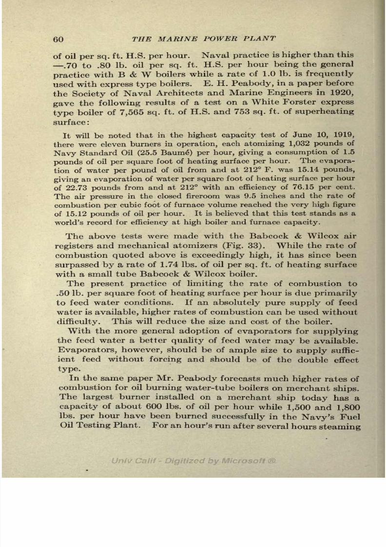
8/3/2019 Marine Power Plant Chaprich
http://slidepdf.com/reader/full/marine-power-plant-chaprich 72/335

8/3/2019 Marine Power Plant Chaprich
http://slidepdf.com/reader/full/marine-power-plant-chaprich 73/335
MARINE BOILERS 61
in one of the tests at the Testing Plant the rate of burning was
run up to 2,238 Ibs. of oil per burner per hour.
41. Boiler Efficiency. The losses in burning fuel under a
boiler will be fully taken up in Chap. V after a study has been
made of combustion. Here we are interested only in the defini-
tion of boiler efficiency. .
Efficiency of boiler and furnace
Heat absorbed by boiler per Ib. of fuel as fired
b.t.u. value of one Ib. of coal as fired.
The efficiency of the boiler is often based on "dry coal" instead
of "coal as fired" and sometimes it is calculated on the basis of
"combustible burned." In the former case weight of the mois-
ture is eliminated from the coal and in the latter case the weight
of the ash and the coal lost through the grate, together with the
weight of the moisture, is eliminated. Care must be exercised
in studying and comparing data of boiler tests to determine which
efficiency is used and to make sure that all efficiencies compared
are on a common basis.
There are other boiler efficiencies used in practice, but as
these are seldom met and are not defined the same by all engineers
they will not be included in this book. The efficiency based on
"coal as fired" is the one commonly used. This, of course,
is an overall efficiency of boiler, grate and firing and is the one of
most commercial interest. For boilers using fuel oil the effi-
ciency becomes:
Heat absorbed by boiler per pound of oil burnedBoiler Efficiency
=b.t.u. value of one Ib. of oil
The analysis of test data from an oil burning water-tube boiler will make
clear the foregoing definitions.
Boiler pressure (gage)= 190.3 Ibs.
Quality =59.2F. superheat.
Feed water temperature =64F.
Oil burned per hour =1,300 Ibs.
Water evaporated per hour =15,973 Ibs.
Boiler heating surface = 3,050 sq. ft.
B.t.u. value of fuel oil =19,311 b.t.u. per Ib.
B.t.u. absorbed by one Ib. of water = rj +qi-q* +cta .= 841.4 +357. 1-32. 1+
(.61X59.2)=
1,202.5 b.t.u.
1 202 ^
Factor of evaporation= =1.24
Actual evaporation per Ib. of oil as fired = = 12 '29 lbs '

8/3/2019 Marine Power Plant Chaprich
http://slidepdf.com/reader/full/marine-power-plant-chaprich 74/335

8/3/2019 Marine Power Plant Chaprich
http://slidepdf.com/reader/full/marine-power-plant-chaprich 75/335
MARINE BOILERS 63
upon. Calculations for the size of boilers are given in Chap.
XIX. Boilers should never be spoken of or thought of in terms
of the horsepower of the main engine but in terms of heating
surface.
44. Comparison of Scotch and Water-Tube Boilers. Both
the Scotch and water-tube boilers have merits and defects. The
Scotch boiler has been almost universally used in the merchant
service; all sea going engineers are familiar with it; firemen can
easily be secured capable of operating it; repairs can be made
in practically every port of the world; and it has a large water
volume and consequently is not as dangerous in the hands of
an inexperienced crew as a water-tube boiler.
The claim is frequently brought forward for Scotch boilers
that they can be used successfully when there is salt water in
the feed system. This is true provided sufficient volume is
given the steam space to prevent priming. This argument is
sometimes carried further, by declaring Scotch boilers are often
necessary as salt water cannot be kept out of the feed system.
With the present designs of condensers and proper attention to
tube packing there is no excuse whatsoever for salt water to
leak into the condensate; so this argument should be given
little weight.
The above comprise the merits of the Scotch boiler. Its de-
fects and disadvantages are many. It has a very poor circula-
tion and steam must be raised slowly. As a result of the poor
circulation
unequal
stresses are set up often causing it to be in
a leaky condition and necessitating frequent and expensive
repairs. On account of the long time required to raise steam
it is particularly bad on short runs where it is frequently cooled
down and heated up. Very often the time required for cooling,
cleaning or repairing, and raising steam again in a Scotch boiler,
decides the length of stay in port. Scotch boilers cannot be
forced as a water-tube boiler can and are apt to be short lived
if anevaporation
rate in service of much over 5 Ibs.
/sq.ft. of
heating surface is maintained.
Because of the severe stresses set up necessitating heavy
construction, the Scotch boiler is practically limited to steam
pressures below 200 Ibs. while water-tube boilers can be built
to carry more than twice this pressure. For the same reasons,
the size of a single ended Scotch boiler is limited to about 4,000

8/3/2019 Marine Power Plant Chaprich
http://slidepdf.com/reader/full/marine-power-plant-chaprich 76/335
64 THE MARINE POWER PLANT
sq. ft. of heating surface while water-tube boilers of 10,000 sq.
ft. are now under construction.
Unless the Scotch boiler is fitted with a waste type superheater
and Howden air heater in the uptakes, or fitted with retarders
and given a long length of tube to reduce the temperature of
the escaping gases, its efficiency will be less than that of the
water-tube boiler. This is especially true if the boiler is oper-
ated on fuel oil at high rates of combustion.
The water-tube boiler has many advantages over the Scotch
boiler. It
occupiesless
space;costs much less for a boiler of
equal capacity; the repairs and upkeep charges are lower; and
it is much lighter. Further, the water-tube boiler has an excel-
lent circulation and small water volume and can be easily
forced without any serious results; steam can be raised quickly
and it can be quickly cooled for repairs. Thus a case will sel-
dom arise where a ship's stay in port is influenced by the boilers.
As higher steam pressure can be carried with a water-tube
boiler, this alone may often be enough to cause the shipownerto decide in favor of this type.
A case is on record where a water-tube boiler was blown down,
a tube removed and steam raised again in 2 hours. While it
is possible to raise steam in a light water-tube boiler in 15
minutes, it is best to allow several hours for heating up the
brickwork and starting the circulation with a cold boiler when
sufficient time is available. With a Scotch boiler 24 hours
should be allowed for raising steam if possible. Steam should
never be raised in less than 5 or 6 hours and an equal amount
of time should be allowed in cooling down. To attempt to
raise steam or cool a Scotch boiler in too short time will bring
undue strain on the boiler because of the poor circulation, and
a leaky boiler will result.
From the foregoing statements, it would seem that the tradi-
tion of the merchantservice,
its
general familiarity,and ease of
handling with an inexperienced crew are the only things which
recommend the Scotch boiler. For the most efficient operation
and reduced operating costs of both ship and machinery the
water-tube boiler should be more universally adopted.
The universal adoption and good service rendered by water-
tube boilers in the U. S. and other navies should be sufficient
recommendation for its use in the merchant service. On account

8/3/2019 Marine Power Plant Chaprich
http://slidepdf.com/reader/full/marine-power-plant-chaprich 77/335
MARINE BOILERS 65
of the great saving and weight, it should be the only type con-
sidered for
high powered passenger ships.J. J. Nelis, formerly senior boiler engineer of the Emergency
Fleet Corp., has given the following statement in "Marine
Engineering"
for January, 1920: "Practically 80 per cent of
the boiler repairs on vessels of the emergency fleet that are now
in operation are being made on Scotch boilers, although only
50 per cent of the boilers in operation are of this type. In
many cases leaks due to poor workmanship of Scotch boilers
cannot be made tight by caulking and variouskinds of
weldinghave been resorted to. Welding even when properly done does
not keep seams of Scotch boilers tight for more than 4 or 5 years,
due to the constant movement of these seams." It should be
borne in mind, however, in connection with the above statement
that many of the boilers built for the Emergency Fleet Corp.
were built under war conditions by inexperienced men and not
by shipbuilders with long experience with Scotch boilers.

8/3/2019 Marine Power Plant Chaprich
http://slidepdf.com/reader/full/marine-power-plant-chaprich 78/335
66 MARINE POWER PLANT
Ia(2
PS
I
5
I
8
I!siO
o
OfiO -(NtS^cO .ftftrH -2 00 -O -COO fi * -<Ot- -OO CO O> OS 'Sffl -O -t>-00 -CO -l>
t~iC -(NOfi "* gOO -00-* -CU5- fli-l X -<O
i-H^-CO -NNO^O5U3 Tt< CO N r-> C
COO 00 M t>- ""* O M< O5iCCO ' -COH
C O C3 CD "5 'M O -
00 O 00 CO t~ "* 00O ifl ft~ "* 00O ifl ft T-( C^I O 1C (M l^.
-(NCCCO ..1C COO CO CO I
< 10 CO -r}1 . . (N <N <N O5icco -g -<NI-I - - -
..-ri-lrHf(O
TT?i :
CO -CM
<N
*
-OSS :-8I> -_S fl
O'
O
OCO001>05 -^ OOJ>00 <* ...... -
ft -oooooo * -^^
00O CO CO CO ^ O CO Tj< T}*
ICCOC O CO CO 1C C
CO- rfO'CO W
CO i-l 1C C5 fl fl C<l 00 CO Tf CO O -O C CO 1-1
1C 1C rH O5 CO 00 * CO 1C CO CO -CO ft CO <*
(N .-^T}(TJ< .(N . . -_.<NOOOOOO -O
S. c
'13. .
00 O 00 CO fl C5 1^ rt* b<. 1C r}< 1C t>- N. t^ 1C O Tf< CM CM r>. <M -00 COOS w T}<
) CO CO O5 <O CO C 00 Tf O5 C ^ CO ^ b- t>- O f< rt ^) CO iC ^ T}< ^ OO 'COcOfl <1C -WCM^O^cO -<NT-H - - - -CN OOOOOO -*f) US.W 1^
CO CM CO i ' i ifi ^ rH i i . t^-CO^
OCCOiCi-( rj(
1C SO fe^OO CO -3 C
t^ rH os oo CM y-CM i* *
OS 00
-Ofi-'-co -
'oiC-co
co-*rM '^J -<N -r- -O - -oo 00^fj-l . r^ . TJ . . . .
rfl .O5fl 1C(M 1C .,5 . . . .fl - . .fl -b. -00
S(M 04 CO>C <N
'
S : ~.
-a'S :
i
: :
'
8-5 :1 : : : :
I\
M
a-S'S allSS IIS22S | i'
-22 Si
g g| gs g gig

8/3/2019 Marine Power Plant Chaprich
http://slidepdf.com/reader/full/marine-power-plant-chaprich 79/335
MARINE BOILERS 67
r-i b- O t~
iO ?4 OCN CN
CO O
S3
-^iMQOCXJOO -Oi-HOOiOO
3 8e?58 c^S8Sco'2SS w
!S00 2
OOO^O 00 r-* 10 O *
Is*- CD lO O t- CO O:
OOtOfei-4- ...,-j
*Ogj C^Q
rH 01 rH rH
..2 "I 5
~ ~
W CO
O?
"<o
- fi
1*1>-S
s a
1
I^ ^ O II II
e)
<u JsJ
1
11 1-8c >-
w fe M I an '2 o H HO S 3SIa w

8/3/2019 Marine Power Plant Chaprich
http://slidepdf.com/reader/full/marine-power-plant-chaprich 80/335
CHAPTER V
COMBUSTION
Part I Combustion of Coal
45. Chemistry of Combustion. Combustion is a rapid chemi-
cal union of fuel and the oxygen in the air. Fuel must first be
brought to the ignition temperature by the application of heat.
At the ignition temperature the hydrocarbons are driven off and
ignited; the remaining fixed carbon unites with the oxygen of the
air forming carbon dioxide (C02). The fuel absorbs heat during
the first stage of combustion, and burns and gives up heat during
the second and third stages.
During the process of burning, the proper amount of oxygen
must be brought in contact with each particle of the fuel so that
complete combustion of the fuel will result and CC>2 be formed.
The exact chemical combinations of the hydrocarbons and ele-
ments in the fuel are rather complicated and a complete analysis
of the reactions taking place during combustion is outside of the
scope of this book. At the completion of the combustion the
carbon hasunited with
oxygen forming C02 and the hydrogen hasunited with oxygen forming H20. Thus
The elements unite in proportion to their atomic weights as
follows:
12 Ibs. C+(2X16) Ibs. = 44 Ibs. C0 2
(2X1) Ibs. H+ 16 Ibs. = 18 Ibs. H2O
Dividing the above by 12 and 2 we have,
C+22/3O =32/3C02
H+80 =9H2
Thus each pound of carbon unites with 2 2/3 Ibs. of oxygen form-
68

8/3/2019 Marine Power Plant Chaprich
http://slidepdf.com/reader/full/marine-power-plant-chaprich 81/335

8/3/2019 Marine Power Plant Chaprich
http://slidepdf.com/reader/full/marine-power-plant-chaprich 82/335
70 THE MARINE POWER PLANT
2 2/3 Ibs. of air are required per pound for complete combustion.
The oxygen for combustion is supplied from atmospheric air
which consists of 23 parts oxygen to 77 parts nitrogen by weight.
The ratio of air to oxygen is 1,000/23=4.35. Therefore 4.35X2.66 = 11.6 Ibs. of air must be supplied per pound of fuel for
complete combustion. For atmospheric air at 60F and 14.7 Ibs./
sq. in. this is equivalent to 11.6/.076= 152 cu. ft. of free air.
The. nitrogen in the air takes no parf in the combustion process
and merely dilutes the uptake gases. The actual theoretical
amount of air required, taking account of the hydrogen and sul-
phur in the fuel, is.
Pounds of air per pound of coal = 11.6C+34.2(H- 0/8) +4.35S.
47. Excess Air. In the foregoing article it was assumed that
the fuel was pure carbon and that perfect and complete combus-
tion was taking place, the exact amount of oxygen being sup-
plied to each particle of fuel at the proper time. In the actual
combustion of coal in a furnace these conditions are impossible.
If the correct amount of air were supplied to burn one pound of
carbon, there would not be sufficient air to burn the hydrogen,
which requires three times as much per pound as carbon.
Also, due to the thickness and unevenness of the fuel bed and
unequal distribution of the entering air, each particle of fuel
would not receive its full amount of oxygen at the proper time.
Under these conditions, part of the combustion would be com-
plete and a large part incomplete and carbon monoxide would
be formed with its resultant loss of 10,100 b.t.u. per pound of
fuel.
To obviate a deficiency of air at any point in the fuel
bed it is necessary to supply 20 to 100 per cent more air than
the theoretical amount. This increase is called excess air.
The actual amount necessary to insure complete combustion
varies with the kind of fuel and the care used in firing. As all
the excess air has to be heated and as a large part of this heat
escapes up the stack and cannot be recovered, the amount of air
used should be kept as low as possible. The loss caused by
incomplete combustion is much greater than that caused by the
dilution of the furnace gases; hence any error should always be
towards too great excess air rather than too little.
The amount of oxygen in the air is 21 per cent by volume, and

8/3/2019 Marine Power Plant Chaprich
http://slidepdf.com/reader/full/marine-power-plant-chaprich 83/335
COMBUSTION 71
as the volume of CO 2 formed is the same as the oxygen used, it
follows that 21 per cent of the volume of the flue gases should
be CO2 if the theoretical amount of air is supplied and perfect
combustion results. With an excess supply of air, the percentage
of CC>2 in the uptake gases decreases, being 10.5 per cent when
the excess air is 100 per cent. The percentage of CO 2 in the
uptake gases thus is an indication of the amount of excess air
supplied. For good operation without the formation of carbon
monoxide the percentage of CO 2 should be between 9 and
16 per cent. Values lower than 9 per cent generally indicate
too large amount of air and values higher than 16 per cent are
generally an indication that CO exists in the uptake gases.
Instruments known as C0 2 recorders are on the market which
give a daily graphical record of the variation of the volume of
C0 2 in the flue gases. These thus serve as a guide for the firemen
in adjusting their air supply and give a permanent record for
the chief engineer and superintending engineer of the boiler
performance.
48. Method of Supplying Air. If all the air were supplied
from below the fuel bed, carbon dioxide (CO2) would be formed
in the lower part of the bed and then later this CO 2 would be
reduced to carbon monoxide (CO) as it came in contact with the
incandescent carbon at the top of the fuel bed. Moreover, as the
hydrocarbons were distilled off from the top of the fire there would
be little or no oxygen present to unite with these gases and liberate
heat by the formation of CO 2 and H 2O. Under these conditions
there would be a large loss of available carbon in the form of COand also smoke would be produced.
To secure proper combustion it is necessary that a sufficient
amount of air be distributed over the top of the fuel bed. This
air must be brought to a high temperature before coming into
contact with the volatile gases, otherwise the gases will be
chilled and smoke result. It is also very essential that air
supplied at the top of the fuel bed should be thoroughly mixed
with the gases so that complete oxidation will take place. This
air supply for the top of the fire is sometimes passed up through
the fuel bed, but more often it is admitted through openings in
the firedoor or at the bridge wall in the rear. The Wager bridge
wall shown in Figs. 26 and 28 is an excellent means of
admitting air to the top of the fire and as the air comes in through

8/3/2019 Marine Power Plant Chaprich
http://slidepdf.com/reader/full/marine-power-plant-chaprich 84/335
72 THE MARINE POWER PLANT
small slots proper mixing will take place. The heating of the
air can be accomplished by means of the Howden heater (Figs. 32
and 11) or by passing the air and gases over incandescent
portions of the fire. Air is especially needed at the top of the
fire after firing when the volatile gases are being distilled off;
hence the practice of covering part of the fire at one time with
fresh coal leaves the incandescent part of the fuel bed to assist in
the combustion of the gases given off from the fresh coal.
49. Losses in Burning Coal. When coal is burned in the
furnace of a boiler there are various losses of heat, some avoidable
and some unavoidable. The result is, that only between 60 and
85 per cent of the heat liberated during combustion is absorbed
FIG. 26. Wager bridge wall fitted with water-tube boiler.
by the water in the boiler. The various losses in burning coal
can be divided up as follows:
1. Combustible in the ash.
2. Moisture in the fuel.
3. Superheating the moisture produced by hydrogen in fuel.
4. Incomplete and imperfect combustion.
5. Heat carried away by stack gases ("dry chimney gases").
6. Superheating of the moisture in air.
7. Radiation.
8. Unburned carbon in the form of smoke.
Moisture in Fuel. The economic loss and the inciease bunker
space caused by moisture in the coal have already been mentioned.
Here we are only concerned with the loss caused during combus-
tion. All the moisture contained in the coal requires heat to
convert it into superheated steam at furnace temperature. As

8/3/2019 Marine Power Plant Chaprich
http://slidepdf.com/reader/full/marine-power-plant-chaprich 85/335
COMBUSTION 73
the gases are cooled in their passage over the heating surface
part of the heat of superheat is given up; but all the heat in this
superheated steam above the uptake temperature is carried upthe stack and is lost. This loss may be expressed in b.t.u. per
hour as follows:
where qi= heat of liquid at atmospheric pressure.
7*1= heat of vaporization at atmospheric pressure.
#2= heat of liquid at temperature of fuel before firing.
c = specific heat of superheated steam.
ta=
degree of superheat in uptake (uptake temperature
212).
w = Ibs. of water fired with coal per hour.
Moisture in the Air. This loss is due to converting the mois-
ture in the air from water at boiler room temperature into
superheated steam at stack temperature. This loss is of no
importance on clear days but increases on damp and foggy days.
If the humidity and quantity of air supplied are known the loss
can be easily computed by the method used in the preceding
article.
Hydrogen in Fuel. This is a loss similar to the two preceding
ones. The hydrogen in the fuel unites with oxygen in the air
forming water. This water absorbs heat when it is converted
into
superheatedsteam and all the heat contained in this steam
above uptake temperature is lost up the stack. The loss in
b.t.u. per hour is expressed as follows: 9(<?i+ri q2+ct,)X coal
fired per hour X per cent hydrogen in fuel.
Incomplete Combustion. This loss already has been dealt with
at length. It is caused by too small an amount or the improper
distribution of the air supply resulting in the formation of carbon
monoxide (CO) instead of carbon dioxide (CO2). The per-
centageof
CC>2in the flue
gasesis an
approximatemeasure of
this loss but the exact loss can only be ascertained by a flue gas
analysis in which the percentage of CO is determined. The
loss in b.t.u. per pound of fuel due to incomplete combustion is
CO= 10
'100CX
CO+CO,

8/3/2019 Marine Power Plant Chaprich
http://slidepdf.com/reader/full/marine-power-plant-chaprich 86/335
74 THE MARINE POWER PLANT
where C = weight percentage of carbon in fuel actually burned.
CO = volume percentage of CO in flue gas.
CO 2 = volume percentage of CO2 in flue gas.
This loss can be practically eliminated by careful attention to
firing, allowing sufficient excess air, and the proper mixture of
the air and combustible gases.
Dry Stack Gases. This loss is always the largest one except
for poorly operated boilers and is one that is unavoidable. It
is caused by the heat carried away by the stack gases. The
temperature of the gases leaving the boiler must always be
higher than that of the steam in the boiler or heat will pass from
the steam to the gases. It is common practice to keep this
temperature about 100 higher than that of the steam. In
order to keep this loss as low as possible, the excess air should
be kept down within reasonable limits but not so low that in-
complete combustion will result. The loss due to stack gases
increases when the boiler is forced, and is generally a large loss
for boilers in destroyers and other high speed craft when oper-
ating at maximum capacity, due to the high temperature of the
stack gases. A considerable portion of the heat in these waste
gases can be recovered by the use of Howden air heaters (Art.
66), waste type superheaters (Art. 79), and economizers (Art.
182). The loss in b.t.u. per Ib. of fuel is,
where W the weight of flue gases per pound of fuel.
c = specific heat of flue gases.
tf= temperature of gases leaving boiler.
ta= temperature of air entering furnace.
By careful firing the amount of excess air can be reduced and
the boiler efficiency increased. With mechanical stokers (Art.
53), pulverized coal (Art. 54), and liquid fuel, because of the
better mixing of the fuel and air, the amount of excess air re-
quired is much less than with intermittent and irregular hand
firing with coal. This accounts for the higher boiler efficiency
obtained with the methods of combustion and the fuels men-
tioned.
Radiation. The loss due to radiation is generally in the neigh-
borhood of 5 per cent and can be reduced by insulation of the
boiler and furnace. Water-tube boilers should have an ade-

8/3/2019 Marine Power Plant Chaprich
http://slidepdf.com/reader/full/marine-power-plant-chaprich 87/335
COMBUSTION 75
quate brick furnace lining to reduce radiation as much as pos-
sible. In high speed craft this furnace brickwork has been
greatly reduced to save weight, but on merchant ships heavy
insulation consisting of two or more thicknesses of brick should
be used (see Fig. 15). Scotch boilers have no furnace radiation,
but the radiation from the shell is large unless carefully lagged.
50. Heat Balance. In all complete boiler tests the various
losses mentioned above are calculated and tabulated. These
losses together with the heat absorbed by the boiler consti-
TABLE VIII. HEAT BALANCES

8/3/2019 Marine Power Plant Chaprich
http://slidepdf.com/reader/full/marine-power-plant-chaprich 88/335
76 THE MARINE POWER PLANT
51. Boiler Efficiency. Boiler efficiency has already been de-
nned in Art. 41. It should be observed here, however, that
the overall efficiency of the boiler and furnace which is the one
usually used, takes account of all the losses given in the preceding
article. The percentage of heat absorbed by the boiler in the
above table is the boiler efficiency as denned in Art. 41.
52. Temperature of Gases in Boiler. The theoretical maxi-
mum temperature in the furnace can be easily calculated from
the calorific value of the fuel and the weight and specific heat
Length of'Boiler =11-8"
Diameter ofBoiler *I5'-o"(Mean)
Working Pressure =180 lb$.(Gauge}
Temperature ofSteam
at180tbs.pressure
AirHeater
Funnel
SteamtoMain Engine
~romSuperheater 453 A
234-56Feet
FIG. 27a. Variations in temperature in a Scotch boiler.
of the flue gases. The actual furnace temperature for coal
varies roughly between 2,000 and 3,000F. depending on the
amount of excess air; for oil fuel the temperatures are higher,
generally being in the neighborhood of 3,000. Figures 27a and
27b show the variation of the temperature of the gases during
their passage through the boiler and are worthy of careful study.
These figures are of special value in studying the temperature
when superheaters are installed. Figure 27b is for a Yarrow
express type water-tube boiler taken from a paper by Alfred
Yarrow before the Institution of Naval Architects, 1912; and

8/3/2019 Marine Power Plant Chaprich
http://slidepdf.com/reader/full/marine-power-plant-chaprich 89/335
COMBUSTION 77
Fig. 27a is for a Scotch boiler and is taken from a paper by
Maurice S. Gibbs before the North East Coast Inst. of Engineers
and Shipbuilders, 1920.
53. Mechanical Stokers. The mechanical stoker so far has
been practically untried on shipboard, although it is giving excel-
2500
Feed
HeatingTubes
FIG. 276. Variations in temperature in Yarrow boiler.'
lent service in
power plantson shore and is almost
universallyused in all large plants using coal. The efficiency of a boiler
fitted with a stoker is nearly the same as when using fuel oil.
The steam necessary to operate the stoker would not greatly
exceed the 1 1/2 per cent required by a fuel oil installation.
Further, the labor expense certainly would be nearly as low as
that for fuel oil and the duties of the firemen will be as easy as

8/3/2019 Marine Power Plant Chaprich
http://slidepdf.com/reader/full/marine-power-plant-chaprich 90/335
78 THE MARINE POWER PLANT
with oil. Stokers will involve some increased weight and space
and the boilers will have to be raised to allow for the installa-
tion of stoker. These factors, however, should cause no serious
difficulties on merchant ships. The increased weight and space
required over hand fired boilers will be offset to some extent
by the smaller boilers required because of the higher rates of
combustion possible with stokers. The boiler will probably not
be raised more than 6 or 8 ft. and any loss in metacentric height
can be made up by an increase in beam. In fact, because of the
better design that can be produced with increased beam it
may even be possible to stow the coal in raised bunkers so that
it can be delivered to the
stoker hoppers by gravity.
With improved bunkering
facilities such as the Michener
bunkering machine, much of
the dirt and expense of bunk-
ering could be eliminated.Mechanical conveyors could
be installed for handling coal
from the bunkers to the stoker
and mechanical bunker trim-
mers could also be used for
trimming the coal in the
bunkers. It is interesting to
note that the methods of
handling coal today on ship-
board are practically the same that were used on the first coal
burning steamship of 70 years ago.
Comparative tests have been made on shore with the Emer-
gency Fleet Corporation's four pass water-tube boiler, both
hand fired and with underfeed stokers (Proceedings A. S. M. E.,
1919). At a rate of combustion of 20 Ibs. dry coal per square
foot of grate surface, the efficiency based on dry coal was 71 per
cent for the hand fired boiler and 75 per cent when fitted with
mechanical stokers. The hand fired boiler in these tests had
an added advantage by being fitted with Wager bridge walls.
The advantages of mechanical stokers over hand firing can
be summarized as follows:
FIG. 28. Wager bridge wall fitted inScotch boiler.
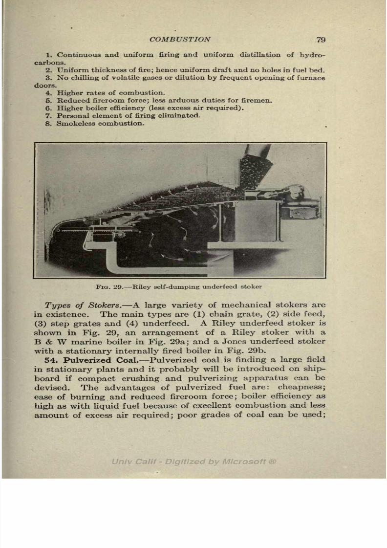
8/3/2019 Marine Power Plant Chaprich
http://slidepdf.com/reader/full/marine-power-plant-chaprich 91/335
COMBUSTION 79
1. Continuous and uniform firing and uniform distillation of hydro-
carbons.
2. Uniform thickness of fire; hence uniform draft and no holes in fuel bed.3. No chilling of volatile gases or dilution by frequent opening of furnace
doors.
4. Higher rates of combustion.
5. Reduced fireroom force; less arduous duties for firemen.
6. Higher boiler efficiency (less excess air required).
7. Personal element of firing eliminated.
8. Smokeless combustion.
FIG. 29. Riley self-dumping underfeed stoker
Types of Stokers. A large variety of mechanical stokers are
in existence. The main types are (1) chain grate, (2) side feed,
(3) step grates and (4) underfeed. A Riley underfeed stoker is
shown in Fig. 29, an arrangement of a Riley stoker with a
B & W marine boiler in Fig. 29a; and a Jones underfeed stoker
with a stationary internally fired boiler in Fig. 29b.
54. Pulverized Coal. Pulverized coal is finding a large field
in stationary plants and it probably will be introduced on ship-
board if compact crushing and pulverizing apparatus can be
devised. The advantages of pulverized fuel are: cheapness;
ease of burning and reduced fireroom force; boiler efficiency as
high as with liquid fuel because of excellent combustion and less
amount of excess air required; poor grades of coal can be used;

8/3/2019 Marine Power Plant Chaprich
http://slidepdf.com/reader/full/marine-power-plant-chaprich 92/335
80 THE MARINE POWER PLANT
no ashes to handle; no stand-by losses; high rates of combustion.
The cost of crushing, drying, pulverizing and delivering to
Lineshafthung from
cylindersmaybebedriven
bychainorbeplacedon ^
flooranddirectconnected<
toengine.
;
Allowone-halfhprsepower; perretortfordrivingsfoktr
This doesnotinclude
\ shaftingor chain losses.
|
Thisspace shouldbe
I
wide enough so that
\fuhtoolsmaube'used
FIG. 29o. Riley underfeed stoker fitted with a marine water-tube boiler.
FIG. 296. Jones stoker fitted in internally fired boiler.
boilers is given by Scheffler and Barnhurst (A, S. M. E., 1919)
as 18 kw-hours per ton of coal. Allowing 11/2 Ibs. of coal per
horsepower per hour, this is equivalent to 1 1/2 per cent of

8/3/2019 Marine Power Plant Chaprich
http://slidepdf.com/reader/full/marine-power-plant-chaprich 93/335
COMBUSTION 81
the boiler output which is practically the same as required for
fuel oil and stokers. Figure 30 shows a boiler fitted for burning
FIG. 30. Burning pulverized coal with Fuller Engineering Co.'s equipmentin stationary boiler.
pulverized fuel with apparatus manufactured by the Fuller
Engineering Co. of Allentown, Pa.

8/3/2019 Marine Power Plant Chaprich
http://slidepdf.com/reader/full/marine-power-plant-chaprich 94/335
Part II Combustion of Fuel Oil
55. General. Oil is burned under boilers by injecting the
oil into the furnace in the form of a fine atomized spray (Fig. 31).
The oil is pumped from the fuel tanks forward and aft to a fuel
tank amidships by the fuel oil transfer pump (booster pump).
The fueloil service
pumptakes the oil from the tank located
amidship and delivers it to the burners under a pressure of
between 100 and 250 Ibs. per square inch. The oil is passed
through a heater on the way to the burners where it is raised to
a high temperature in order to reduce its viscosity so that it
can be easily atomized into a fine spray by the burner. The
air for combustion is admitted through openings (registers)
around the burner at high velocity and mixes thoroughly with
the atomized oil in the furnace, resulting in complete oxidation
of the fuel and the liberation of heat.
56. Fuel Oil Burners and Mechanical Atomization. In me-
chanical atomization the oil is atomized by the action of cen-
trifugal force. The oil is given a whirling motion in the burner
either by means of a helical groove or passage, or by tangential
holes. The oil is delivered to the burner under high pressure
and the rotary motion imparted by the burner breaks the oil up
into a fog-like spray. The oil leaves the burner in a thin conical
sheet (Fig. 31) and at once mingles with the air which enters
around the burner at high velocity. Figure 31 shows an illus-
tration of the Schutte-Koerting burner and register. Heating of
the oil is essential to reduce its viscosity so that the burner can
perform its function; the temperature to which the oil must be
heated varies with the viscosity of the oil and ranges between
100 and 250. For successful atomization, the oil should beheated so that its viscosity is between 10 and 3 Engler scale,
depending on the flash point of the oil.
The capacity of a given burner depends upon the pressure of
the oil increasing the pressure increases the capacity. The
maximum capacity of burners used in the merchant service is
about 600 Ibs. of oil per hour while 1,500 Ibs. per hour and even
82

8/3/2019 Marine Power Plant Chaprich
http://slidepdf.com/reader/full/marine-power-plant-chaprich 95/335
COMBUSTION 83
KOERTING PATENT
OIL FIRING SYSTEMON BOILERSOT
TORPEDO BOAT DESTROYERS
A- BOILER FRONT CASING
B- AUTOMATIC AIR DOORS
C- AIR REGISTER AND SLIDE'
D- REGULATING HANDLE
E- REMOVABLE BURNER
F- BURNER CLAMP
G- OIL SHUT orr COCK
H- STRAINER
J- OIL DISTRIBUTING RPC
SCHUTTE a KOERTING Co.
PHILADELPHIA.PA.
FIG. 31.

8/3/2019 Marine Power Plant Chaprich
http://slidepdf.com/reader/full/marine-power-plant-chaprich 96/335
84 THE MARINE POWER PLANT
one ton of oil per hour has been attained during tests with naval
boilers at the U. S. Fuel Oil Testing Plant. 1
The capacity of a boiler is increased both by increasing the
oil pressure at the individual burners and by adding additional
burners.
In stationary installations steam and compressed air are used
for atomizing the oil in the burners. The steam atomizer is
most universally used and gives excellent results. However,
because of the steam required for operation and the necessity
of
make upfeed to
replacethis steam
used,steam
atomizersare not used on shipboard. The mechanical atomizer described
FIG. 32. Arrangement of Howden system of forced draft on Scotch boiler. (Oil.)
above has been developed in marine work and while perhaps
slightly less efficient than the steam atomizer, it gives excellent
results and entire satisfactory performance.
57. The Babcock & Wilcox Mechanical Atomizer. Figure 33
shows a drawing of the B & W atomizer.
A conical cast iron casting, 1, is placed in the front wall of the boiler
setting as an orifice through which the air and oil are admitted to the
furnace. The main register casting, 2, is fitted with automatic doors,
3, by which the quantity of air supplied to the burners may be regulated or
shut off entirely. These doors are so designed that they will close auto-
matically in case of a flare-back in the furnace or the bursting of a boiler
1 E. H. Peabody, "Recent Advance in Oil Burning." Trans. Soc. N. A.
& M. E., 1921.

8/3/2019 Marine Power Plant Chaprich
http://slidepdf.com/reader/full/marine-power-plant-chaprich 97/335
COMBUSTION 85
tube, thus protecting the fireman who may be standing in front of the
boiler. A cover plate, 4, is attached to the front of the register casting,
and a radiation guard, 5, is held between them. The operation of the
automatic air doors, 3, is controlled by four cams, 6, forming part of a
spider casting which can be rotated by the handle 7. By moving the
handle to the extreme right of the slot through which it slides (the position
shown in Fig. 33), all the air doors are closed; by moving it to the left
the doors are gradually opened.
Passing through the center opening in the cover plate, 4, is a hollow
cylindrical distance piece having at its outer end a quick detachable
coupling, 9, and yoke, 10. To the other end of this distance piece is
FIG. 32 Arrangement of Howden system of forced draft on Scotch boiler. (Coal).
fastened an aluminized-steel conical shaped impeller plate, 11, for regu-
lating the distribution of air at the nozzle of the burner. Passing through
the distance piece is the mechanical atomizer, 13, which is held in place
and connected to the fuel oil supply lines through the coupling, 9, and
yoke, 10, thus making the atomizer, 13, the distance piece and the center
impeller, 11, a rigid unit when in operation. The distance pieceis
so
designed that it may be moved along its axis, thus moving the impeller
plate, 11, in and out with reference to the cone, 1, and decreasing or
enlarging at will the clear area for the passage of air around the outside
of the impeller plate. The distance piece is held in place by a set screw, 12.
The atomizer ends in a burner which imparts a rotary motion to the
oil as it emerges in a conical spray. The burner ejects this spray through
a central opening in the impeller plate, 11, which plate has blades like

8/3/2019 Marine Power Plant Chaprich
http://slidepdf.com/reader/full/marine-power-plant-chaprich 98/335
86 THE MARINE POWER PLANT
those of a fan to give a rotary motion to the air as it enters the furnace
around the burner tip. The cone, 1, also has blades which give a whirling
motion to the air entering around the edge of the impeller plate, this air
being directed along the axial line of the burner by the walls of the trun-
BABCOCK & WILCOX
MECHANICAL ATOMIZER
FOR FUEL Om
SECTION A-B
FIG. 33. Babcock & Wilcox atomizer.
cated cone. The operator controls the furnace conditions by the adjust-
ment of the boiler dampers, the air supply of the burners, and the pressure
and temperature of the oil.
58. Furnaces for Burning Oil. The furnace design is an
important factor for boilers using fuel oil. Grates, furnace
doors and other fittings installed when coal is used are, of course,

8/3/2019 Marine Power Plant Chaprich
http://slidepdf.com/reader/full/marine-power-plant-chaprich 99/335
COMBUSTION 87
not fitted. The combustion chamber must be large enough so
that the flames of theburning
oil do not come in contact with the
brickwork or boiler heating surface, otherwise carbon will be
deposited on the brickwork and tubes and smoke will result.
The furnace must be lined with refractory brick that will radiate
the heat and assist combustion (Fig. 18). The refractory brick
is backed up by insulating brick to keep the heat of the furnace
from radiating into the fireroom. This brickwork is securely
fastened to the boiler casing by special bricks to which hook
bolts are attached. TheFoster water-tube boiler has a
liningof 9-in. firebrick backed by two thicknesses of 2 1/2-in. insulating
brick. (See Fig. 15.) This arrangement keeps the furnace
casing below 100 at the hottest part. In naval boilers in order
to save weight, the thickness of the brickwork is greatly reduced
and the radiation from the furnace walls is taken care of by the
circulation of air in a space left for this purpose between the
furnace walls and casing. With express boilers the thickness of
the furnace brickwork is reduced to 4 1/2 ins. against 14 ins. usedin the Foster boiler.
59. Air Requirements with Fuel Oil. The air for combustion
is admitted at high velocity through specially designed tuyeres or
registers surrounding the burner.
The theoretical air required for combustion can be computed
from the formula given in Art. 46, namely,
Pounds of air
per poundof oil =
11.6C-f34.2(H-O/8)+4.35S.Because of the larger percentage of hydrogen
r
present, oil theoreti-
cally requires more air than coal. The exact amount varies
with the analysis of the fuel but is generally very close to 14 Ibs.
of air per pound of oil. This is equivalent to 184 cu. ft. of free
air at 60F. The amount of excess air necessary is much less
than required for coal because of the facility with which the oil
spray and air mix in the furnace. With careful management
10 per cent excess air is sufficient and 30 per cent should be the
maximum for good performance. This small amount of excess
air accounts in a large measure for the increased boiler efficiency
with fuel oil. The reader should refer to the heat balances,
Table VIII, for a comparison of the losses with oil and coal burn-
ing boilers. Naval vessels use a larger amount of excess air than
necessary for good performance in order to do away with smoke.

8/3/2019 Marine Power Plant Chaprich
http://slidepdf.com/reader/full/marine-power-plant-chaprich 100/335
88 THE MARINE POWER PLANT
Fuel is here sacrificed for military reasons. No air should be,
admitted to the boiler except at the register; air leakage in the
casings should be avoided. The correct amount of air can often
be ascertained by the behavior and color of the flame.
60. Method of Operating with Oil Fuel. The following
description of the method of operating an oil fired boiler is taken
from an excellent paper by J. J. Hyland, U. S. N., in the Journal
of the S. N. E., May, 1914:
Suppose no steam is on the plant, the boilers all being cold and no steam
or air available. A hand pumpis
connected up to the discharge end of
the burner line and the hand-pump suction taken from a 5-gal. can filled
with oil. The pump is started and the pressure brought up to and kept
at about 200 Ibs. per square inch, the pressure being kept as steady as
possible. For this purpose, the three-crank pump of the Schutte-Koerting
Co. is a very good one. A torch made of a hooked rod with either waste
or asbestos-ball wicking on the end is dipped in the oil. The addition of
a little kerosene or gasoline to the torch improves matters. The torch
is lighted; all the registers are opened wide to give as much air as possible
to the boiler. Fortunately oil-burning boilers are not provided with
dampers, which would be a menace in unskilled hands. The burner is
opened and lighted and the pump kept going constantly. Unless the oil
is a light oil whose viscosity is 8 or below, at 70 F., the torch will have to
be kept up to the burner constantly until the steam forms and the vis-
cosity of the oil is reduced by heating to 8 or below, when the torch maybe withdrawn. When steam pressure has reached 75 or 100 Ibs., put
steam on the oil pumps and heaters and cut out the hand pump. Put
steam on the forced-draft blower and get ready to put on other burners;
start blower slowly, open air registers wide and light burner. As soon as
it is lighted, speed up the blower until you are sure the air pressure is
sufficient to prevent vibration and flarebacks. Then set the vanes to the
proper openings on the air registers. Always run with the air registers
throttled down it gives a better regulation and a higher velocity to the
air and ensures smoother running.
Until the boiler furnace is well heated an excess of air will be needed to
prevent smoke. When the furnace becomes heated the air can be cut downto the proper amount. Cut in other burners as needed, first being sure
the register is set and open to the proper amount. In case of vibration
cut out a burner till the blower can be speeded up to give sufficient air.
Run with very light smoke. Keep a half glass of water in the boiler;
if the water level is too high the boiler will prime. It is a well known fact
that as burners are added to a boiler, forcing it more, the water level rises,
and vice versa. This should be provided for in operating the feed pumps.

8/3/2019 Marine Power Plant Chaprich
http://slidepdf.com/reader/full/marine-power-plant-chaprich 101/335
COMBUSTION 89
Never cut out all the burners at one time on a boiler operating at full
speed.The water level will
dropout of
sightand
give you manyan
anxious moment until you get it in sight again. In addition, operating
with oils of 21 to 17 B. gravity, the relief valve of the oil pump shows a
decided tendency to stick. If you shut down a boiler suddenly with the
oil pump running, there is danger of bursting the oil lines and causing
a fire that might ruin the ship. Slow the pump down until the pressure
is low enough to cut it out altogether; then close the burner valves.
Merchant ships generally start up when cold by using the
steam generated by the donkey boiler or by a supplyof steam
from shore or another ship. A high pressure is needed in starting
with cold and heavy oil. When steam is available it is turned
onto the oil heater and the oil is recirculated through the piping
and heater, the burners being closed until the viscosity has
been reduced sufficiently to insure successful atomization in the
burners.
When reciprocating pumps are used for fuel oil it is necessary
to install a large air chamber to prevent fluctuations in pressureat the burners. Because of the necessity of a steady pressure
at the burners, reciprocating pumps are not very satisfactory.
The latest and best practice is to use the Quimby screw pump,
or one of similar type, that gives a steady and continuous supply
of oil to the burners.

8/3/2019 Marine Power Plant Chaprich
http://slidepdf.com/reader/full/marine-power-plant-chaprich 102/335
CHAPTER VI
DRAFT
61. General. In order for the air required for combustion to
enter the furnace and for the products of combustion to flow over
theheating
surface andup
the stack there must be a difference
of pressure, or draft, between the air in the fireroom and the
gases in the uptake. This difference in pressure is necessary to
overcome the resistance offered by the fuel bed, the boiler baffling,
and uptakes. Boiler draft is analogous to the flow of water in
hydraulics a difference in pressure head is required to create
velocity head and overcome the lost heads due to pipe friction,
valves, sudden enlargement, etc. The draft may be produced
by building up a positive pressure in the fireroom or ashpit
greater than that of the atmosphere, or by reducing the pressure
in the uptake below that of the fireroom. The draft, or differ-
ence in pressure, must be sufficient to overcome the resistance of
the fuel on the grate (Rp) ;the resistance of the boiler passages
(RB); the resistance through the superheat (R s) and resistance
through the Howden air heater (Rn), if one is fitted.
Draft may be either natural or mechanical. Natural draft
is produced by the suction of a stack or by the wind, while
mechanical draft is an artificial draft produced by fans, blowers
or steam jets. Mechanical draft on shipboard is always pro-
duced by fans or blowers. Steam jets find no use whatsoever
on account of the large expenditure of steam which would
require large quantities of make-up feed. The railroad loco-
motive is a common example of draft by steam jet, where the
steam fromthe
cylindersis
exhaustedinto the stack.
Mechanicaldraft is divided into two types: Forced draft where a pressure is
built up in the ashpit greater than the atmosphere, and induced
draft where the pressure in the uptakes is reduced by a fan
which draws the gases through the boiler and forces them upthe stack. As the difference in pressure required for boiler
draft is very small it is customary to express it in inches of
90

8/3/2019 Marine Power Plant Chaprich
http://slidepdf.com/reader/full/marine-power-plant-chaprich 103/335
DRAFT 91
water instead of pounds per square inch. This gives a very
convenient meansof
measuringdraft.
62. Natural Draft. Natural draft is similar in principle to
induced mechanical draft. It is produced by the difference in
weight between the column of hot gases in the stack and a
column of cold air of the same height
as the stack. Natural draft varies with
the height of the stack, the temperature
of the stack gases and the temperature
of the outside air.
Consider an apparatus similar to that
shown in Fig. 34. Let A be a long pipe,
H ft. high, filled with cold air at tem-
perature ta and B a pipe of the same
height and diameter filled with hot
gases at temperature ts . At C a flex-
ible diaphragm is fitted as shown. The
weight of a cubic foot of air at 32F.and at sea level is .0807 Ib.; the weight IL
of a cubic foot of stack gas under simi-
lar conditions is approximately .085
Ib. The weight, or pressure exerted, by the column of air, A, is,
.0807X492- XH pounds per sq. ft.
B
FIG. 34.
The pressure exerted by the column of hot gases B, is
D .085X492^^ .
460+1 1
Xtf pounds per sq. ft.
The difference in pressure on the diaphragm C, due to the
heavier column of air, is
p=p _p = (.0807x492)g_(.085x492)g460+ta 460-M,
39.6 41.8
If this is converted to inches of water, we have to divide by62 5
=5.2 Ibs. (1 inch of water pressure being equal to 5.2 Ibs.
per sq. ft.).
H(7.63 8.05
\460+*a 400+4inches of water

8/3/2019 Marine Power Plant Chaprich
http://slidepdf.com/reader/full/marine-power-plant-chaprich 104/335
92 THE MARINE POWER PLANT
If the diaphragm at C in Fig. 34 is replaced by a furnace and fuel
bed that will maintain the stack B at a temperature ^ higher
than the outside air we have an example of draft created by a
stack. The pipe A can be removed for the column of cold air
equal in area and height to column B will still exist.
The above formula can now be used to calculate the differ-
ence in pressure or draft measured in inches of water created
by a stack.
Suppose, for example, air is at 70F., gases leave the boiler
at 500F., and the height of the stack is 100 ft. The draft under
these conditions is,
The formula may be transposed to give the height of stack Hin feet necessary to produce a required draft,
7 -63 8 -05
Thus, if 3/4 in. draft were necessary with stack gases at 550
and outside air at 60F.,
520 1010
The height given by the above formula is the theoretical
height without friction. It is customary in using the formula
to take the temperature of the gases at the base of the stack
which is known, instead of the mean temperature in the stack
which is generally unknown. In practice the height of the stack
is increased about 25 per cent to allow for the friction losses in
the chimney and to allow for the fact that the mean stack tem-
perature is lower than that at the base of the stack. Likewise,
for a given height of stack the actual draft obtained would beabout 80 per cent of that obtained by the formula. The formula
now becomes,
Actual P = .80# ( -^- - -r^- ] inches of H 2O
A i IT i OK D / 7.63 8.05Actual # = 1.25 P+l -^- -
4^-

8/3/2019 Marine Power Plant Chaprich
http://slidepdf.com/reader/full/marine-power-plant-chaprich 105/335
DRAFT 93
The movement of the air across the top of the stack, due to
the speed of the ship or a head wind, will increase the draft
appreciably; a following wind may reduce the movement of air
across the top of the stack to zero and hence give a draft due
only to the height of the stack. Likewise, a low outside tem-
perature (ta) will increase the draft as shown by the formula.
However, it is not wise to rely too much on these factors, for
the full required draft should be obtained on a summer's day
with a following wind.
The intensity of natural draft, therefore, is dependent solely
on the height of the stack above the grate and the temperature
of the gases leaving the boiler. As high boiler efficiency requires
a low exit temperature for the gases, we see that a strong draft
is only created at the expense of boiler efficiency. However, as
was pointed out in Art. 39, the gases leaving the boiler must
always be at a temperature of at least 100 higher than that of
the steam. For 250 Ibs. pressure this would be about 500F.
The temperature of the gases leaving the boiler, in practice,
ranges between 500 and 550F. for boilers operating at good
efficiencies.
The argument has often been advanced for stationary plants
that natural or "chimney draft" is obtained only at the expense
of the heat in the flue gases. Where economizers can be used
for heating the feed water and the gas temperature reduced to
300 this argument holds good; and chimneys require energy to
operate them as well as fans. For marine installations, however,
where economizers are not practical (see Art. 182) natural draft
can be obtained without cost.
As the intensity of natural draft is fixed for good operating
conditions by the height of the stack, for an ordinary cargo ship
the draft is thus limited to about 1/2 in. of water. For high
drafts or where any flexibility is desired, mechanical draft must
be used.
63. Forced Draft. Forced draft consists in creating a posi-
tive pressure greater than that of the atmosphere in the ashpit
in coal burning boilers or around the registers in oil burning
boilers. For coal burning boilers the draft may be produced either
by the closed ashpit method or by the closed stokehold method. In
the former, the ashpit is sealed tight and put under pressure by
the blower; in the latter the whole stokehole is sealed and put

8/3/2019 Marine Power Plant Chaprich
http://slidepdf.com/reader/full/marine-power-plant-chaprich 106/335
94 THE MARINE POWER PLANT
under pressure. The closed stokehole system is universal in
naval vessels but used very little in the merchant service. This
system has many advantages but has one serious disadvantage,
in that the approach and exit from the fireroom can only be
made through air locks.
In the closed ashpit system the pressure in the ashpit and fur-
nace is greater than that in the fireroom; so unless the draft is
shut down when opening the furnace doors the gases and flames
will be blown out into the fireroom causing difficulty and serious
danger in stoking. In the closed stokehole system, the wholefireroom is under the same pressure as the ashpit. Due to the
loss through the fuel bed the pressure in the furnace is slightly
less than that in the fireroom. Under these conditions upon
opening the furnace doors there is a rush of air from the fireroom
into the furnace instead of a blast of flame and gases outward.
There is a small loss due to the dilution of the gases, and a larger
quantity of air must be supplied because of the entrance of air
through the furnace doors. With natural draft the pressure
in the fireroom is also greater than that in the furnace so that
there is no outward blast upon opening the furnace doors.
64. Induced Draft. With induced draft the fans are placed
above the boilers and draw the hot gases from the uptakes and
deliver them up the stack under pressure. Induced draft is
thus an intensified natural draft and has the advantages of
naturaldraft, namely,
that the draft does not have to be shut
down when firing. Because of the larger volume of gases hand-
led by the fans in the induced draft system the fans are nearly
twice the size of those used with forced draft. The density of-
the gases, however, is less; so the fan horsepower is no greater.
65. Types of Draft with Fuel Oil. When burning oil the air
may be brought to the air registers from the fans through ducts
or false boiler fronts; or the closed stokehole system may be
employed. Natural draft and induced draft lend themselves
readily to oil burning because of the simplicity, and the absence
of all draft ducts and equipment in the fireroom. Induced
draft was installed to a very large extent during the recent war
due to the unfamiliarity of the engine force with water-tube
boilers.
66. Howden System of Forced Draft. In this system the air
for combustion is forced by a fan over the outside surface of a

8/3/2019 Marine Power Plant Chaprich
http://slidepdf.com/reader/full/marine-power-plant-chaprich 107/335
DRAFT 95
.5

8/3/2019 Marine Power Plant Chaprich
http://slidepdf.com/reader/full/marine-power-plant-chaprich 108/335
96 THE MARINE POWER PLANT
nest of tubes located in the uptake. The products of combus-
tion after leaving the boiler pass through the inside of these
tubes on the way to the funnel. This nest of tubes is known as
a Howden air heater and is clearly shown in Figs. 11 and 32.
The air from the fan after leaving the air heater passes down
through passages on either side of the uptake into a reservoir
surrounding the furnace fronts (Figs. 36a and 36b). From here
the air is admitted to the ashpit and above the fire by valves
in the furnace front. In principle, the system is similar to forced
draft with closed ashpit already mentioned. The essential fea-
tures of the system are the air heater which raises the tempera-
ture of the air for combustion to about 250F. and the special
furnace front for admitting air above and below the fire.
The absorption of the heat from the waste gases by the air
for combustion, increases the efficiency and capacity of the boiler,
improves the combustion, and, because of the more uniform
temperature maintained in the furnace, increases the life of the
boiler. The furnace fronts acting as air reservoirs prevent radi-ation to a large extent from the furnaces and thereby give a
cooler fireroom.
The furnace front for coal burnng boilers is fitted with a
safety guard so that the furnace doors cannot be opened until
the air supply to the ashpit has been shut off. This prevents
any danger of the flame blowing through the furnace door
when it is opened for firing. When the furnace doors are open
there is no air supply to the ashpit but hot air is admitted
through the valves to the top of the fire. This air is passed
from the valves vertically downward across the opening forming
a sort of screen and thereby prevents the entrance of cold air.
This arrangement is a great improvement over natural or in-
duced draft and the closed stokehold.
The Howden forced draft system is adopted almost universally
when mechanical draft is used with Scotch boilers. Altogether
about 20,000,000 I.H.P. have been fitted with Howden draft.
The heat in the waste gases is recovered and put to an economical
use thereby reducing the fuel consumption. Howden air
heaters can be used successfully even when waste type super-
heaters are fitted below them in the uptake, Fig. 11.
Howden draft is used with oil fuel as well as coal. Figures 32
and 36b show the furnace front and arrangement of air admission

8/3/2019 Marine Power Plant Chaprich
http://slidepdf.com/reader/full/marine-power-plant-chaprich 109/335
DRAFT 97

8/3/2019 Marine Power Plant Chaprich
http://slidepdf.com/reader/full/marine-power-plant-chaprich 110/335
98 THE MARINE POWER PLANT

8/3/2019 Marine Power Plant Chaprich
http://slidepdf.com/reader/full/marine-power-plant-chaprich 111/335
DRAFT 99
when using fuel oil. This system is especially advantageous
with Scotch boilers using fuel oil because of the higher tem-
perature in the uptake.
67. Fans. Either slow speed plate fans are used or the
higher speed type similar to the Sturtevant "Multivane,"
FIG. 37. Sturtevant turbine-driven fan as used on destroyers.
depending on the space available and the amount of air to be
handled. Two reciprocating engines are as a rule fitted with
each fan so that one can be overhauled without shutting down
the fan (Fig. 35). The fans for the forced draft as a rule are
located above the boilers or high up in the engine room. By
withdrawing the air supply from the engine room it helps to
ventilate and cool the engine room.

8/3/2019 Marine Power Plant Chaprich
http://slidepdf.com/reader/full/marine-power-plant-chaprich 112/335
100 THE MARINE POWER PLANT
Figure 37 shows a type (Sturtevant) of high speed fan used on
destroyers. This fan is driven at high speed by a direct con-
Draft Required between furnace and ash pit inches of water
FIG. 38. Draft required with various kinds of coal.
nected turbine and supplies large quantities of air under high
pressure. This fan discharges air around the whole periphery

8/3/2019 Marine Power Plant Chaprich
http://slidepdf.com/reader/full/marine-power-plant-chaprich 113/335
DRAFT 101
instead of at one place on the periphery as is the case with the
ordinary type of fan. The fan illustrated runs at 1,350 r.p.m.and delivers air at 7 in. static pressure.
68. Draft Required when Burning Coal. The intensity of the
draft required varies with the rate of combustion, for as the
rate of combustion is increased the fuel bed becomes thicker
and a larger volume of gas is passing through the boiler. The
required draft in inches is given by the equation,
P = Rp + RB + RS + RH-
The resistance of the fuel bed (RF) is given in Fig. 38 for
various types of coal. This data has been compiled from
experiments by the Babcock & Wilcox Co. The resistance or
loss of draft through the boiler (RB)varies with the type of
boiler and the rate of combustion. The following figures cover
the range of hand firing:
Water-tube boilers 10 -.30 in.
Scotch boilers 20 -.40 in.
The loss (Rs) through waste type superheaters is about 0.20
in. and the loss through Howden air heater including ducts
and dampers is about .30 in.
Example. Find the draft required to burn 20 Ibs. of coal per sq. ft.
G.S. per hour in a scotch boiler fitted with a Howden heater and waste type
superheater.From curves, Fig. 38, the loss between furnace and ashpit for semi-
bituminous coal = 0.26 in. .26 in.
Loss through boiler = .34 .34
Loss through superheater= .20 .20
Loss through Howden air heater = .30 .30
Total draft required 1.10 in.
69. Draft Required when Burning Oil. All the air for burning
fuel oil is admitted at the registers surrounding the burners.
As already pointed out it is very important that air should not
be admitted at any other point. Mechanical oil burners require
a fairly high velocity of air at the registers so that the air and
oil spray will mix properly in the furnace. Air pressure is
required to create this velocity at the tuyeres as well as overcome
the losses through boiler passages, superheaters, etc. Natural

8/3/2019 Marine Power Plant Chaprich
http://slidepdf.com/reader/full/marine-power-plant-chaprich 114/335
102 THE MARINE POWER PLANT
draft, forced draft and induced draft are all used with oil fuel.
At low rates of combustion natural draft can be used more readily
with oil than with coal. When forced draft is used withoutthe closed stokehold system the air must be conducted from the
fan to the register through ducts. The Howden draft already
mentioned is ideal for this. With natural, induced draft or
closed stokehold force draft, air is admitted to the register directly
from the fireroom.
The amount of draft carried when burning fuel oil varies over
wide ranges for the same rate of combustion, depending on the
furnance volume, velocity of air used and number of burners in
operation. The Navy practice is to use a larger quantity of
excess air for military reasons than in the merchant service and
a higher air pressure is used to prevent flarebacks from gun fire.
In fixing on the required air pressure recourse should be made to
test data on the boiler in question.
70. Area of Stack. Various empirical formulae have been
devised for the area of
chimneybased
uponboiler
horsepowerand height of stack. These are far from satisfactory and are
not applicable to marine boilers. Good marine practice is as
follows :
1 sq. ft. stack area for each 150 Ibs. of coal burned per hour.
1 sq. ft. stack area for each 200 Ibs. of oil burned per hour.
In naval vessels the area of the stack is generally reduced over
the above. With fuel oil thepractice
is to allow 1
sq.
ft. area
for each 300 Ibs. oil burned per hour and still further reductions
in area can be made without reducing the boiler capacity. The
area of the stack should of course vary with the amount of
excess air used. The area can be easily computed by calculating
the volume of gas passing up the chimney per hour and allowing
a velocity of about 20 ft. per second.

8/3/2019 Marine Power Plant Chaprich
http://slidepdf.com/reader/full/marine-power-plant-chaprich 115/335
CHAPTER VII
COMPARISON OF COAL AND FUEL OIL FOR
STEAMSHIPS
In making a comparison between coal and fuel oil for generating
steam on shipboard, the problem should be considered carefully
from every angle, for there are many features connected with use
of fuel on shipboard that have little or no influence on shore.
Some of the points to consider are:
Cost
Weight
Bunker space required
Availability and future supply
Adaptability
71. Cost Comparison. In making a study of the costs of the
two kinds of fuel, the comparison should be based on the amount
of fuel necessary to produce equal amounts of steam under the
same conditions of feed temperature and boiler pressure. In
order to make this comparison certain assumptions must be made
regarding calorific value of the fuel and boiler efficiency. Fair
average figuresfor calorific
values are, 14,300b.t.u.
perIb. for
coal and 18,800 b.t.u. for fuel oil. The boiler efficiency when
operating with coal has been assumed as 69 per cent and with fuel
oil as 75 per cent. These efficiencies are for operation under
the best of conditions; trials will often show higher values and
generally efficiencies under working condition will be lower.
However, the figures given are comparable, regardless whether
or not they satisfy a particular case. The weight of oil has been
taken as 7.75 Ibs. per gallon (58 Ibs. per cu. ft.).
With the above figures, the ratio of the heating value of a
pound of oil to a pound of coal becomes:
18,800X.75
. 14,300X.69
The following table gives the costs of oil per gallon, per ton,
103

8/3/2019 Marine Power Plant Chaprich
http://slidepdf.com/reader/full/marine-power-plant-chaprich 116/335
104 THE MARINE POWER PLANT
and per barrel over a wide range together with the cost of coal
per ton corrected to the same calorific value and boiler efficiency
as fuel oil. Thus, if coal is $6.08 per ton, it would be just as
cheap to buy fuel oil at $8.70 per ton ($.03 a gallon), as the same
amount of steam could be raised in each case for the same fuel
cost. In other words, one is getting more available b.t.u.'s
in a ton of oil than in a ton of coal and hence would be justified
in paying a higher cost per ton for the former. Both prices
are for the fuel in the bunkers.

8/3/2019 Marine Power Plant Chaprich
http://slidepdf.com/reader/full/marine-power-plant-chaprich 117/335
COMPARISON OF COAL AND OIL 105
Oil burning boilers can be operated at a higher rate of combus-
tion than coal burning boilers as the enduranceof the fireman
is not a factor; hence in many cases less heating surface will be
required for oil than for coal, resulting in a cheaper and smaller
boiler.
The efficiency of the coal burning boiler has been taken as
69 per cent and the oil burning boiler as 75 per cent in the above
comparison. This, of course, assures continuous operation.
For intermittent service, duty in port, banking fires, etc., the
efficiency of the coal fired boiler would be greatly reduced whilethat of the oil fired boiler would be practically the same. Coal
fired boilers in stationary plants show as high as 70 per cent
efficiency under test conditions while the average yearly operating
efficiency is between 60 and 65 per cent. Thus we can claim
the elimination of stand-by losses and losses in port for the oil
installation.
72. Bunker Space. Fuel oil occupies about 40 cu. ft. per
ton against 50 cu. ft. for coal. Thus oil requires about 80 percent of the bunker space necessary for coal. If this is corrected
by the difference in calorific value and boiler efficiency we have
That is, the amount of oil necessary to produce the same amount
of steam under the same conditions occupies about 56 per cent
of the bunker space required for coal. In addition to this,
liquid fuel can be stowed much more conveniently than coal;
and the double bottom and other places not accessible for coal
can be readily used for oil. How much of this saving in bunker
space can be used for stowage of cargo depends to a large extent
on the design of the ship. An actual layout would have to be
made to get comparative figures. It is evident, however, that
there will be a very large saving in space available for cargo.
73. Weight Comparison. A comparison of weights of the
two fuels is decidedly in favor of the fuel oil. As already shown
the ratio of weight is
14,300X.69
18,800X.75
This shows that fuel oil to produce the same amount of steam

8/3/2019 Marine Power Plant Chaprich
http://slidepdf.com/reader/full/marine-power-plant-chaprich 118/335
106 THE MARINE POWER PLANT
as coal weighs only 70 per cent as much as the coal or the coal
weighs 43 per cent more than the fuel oil.
The saving in fuel weight gives the oil burning ship a larger
net deadweight carrying capacity. This is also accompanied by
an increase in hold space as previously pointed out.
For a slow ship on a short voyage the saving in bunker space
and fuel weight, and to a considerable extent fuel costs, may not
be very important. However, as the length of the voyage
becomes greater or speed is increased both of the factors become
of more and moreimportance.
74. Adaptability. Fuel oil is much easier and cleaner to handle
on shipboard, and much easier and quicker to put in the bunkers,
and results in a much cleaner ship. The difference in comfort
in the fireroom is beyond comparison.
75. Availability and Future Supply. From the above analysis
it appears evident that with the present prices of fuel, the only
one to consider is fuel oil. Even with the price of oil higher
per ton than coal the factors of space, weight, reduced crew, andconvenience of handling would still give oil by far the advantage.
There are, however, two other factors of greater importance
than those given. The first is the possibility of fueling an oil
burning ship at the various ports of call;and the second and most
important of all is the question of the future oil supply of the
world.
Geologists of high rank tell us that at the present rate of
consumption America's supply of petroleum will be falling off
rapidly in 10 or 15 years. With this rapidly decreasing supply
of petroleum and the increasing demands for gasoline and fuel oil,
the price of fuel oil is bound to rise steadily. Anotherfactor that
will increase the price will be the demand of fuel for use in the
Diesel engines of the world's growing fleet of motorships.
On account of the much smaller fuel consumption of the Diesel
engine,the
motorshipwill be able to
operate longafter the oil
burning steamship has ceased to be an economical ship. A
study of the table given at the opening of the article would lead
to the conclusion that when oil reaches a value around 8 to 10
cents a gallon the coal burning ship would be more economical
than the oil burning ship, especially if the price of coal reduces
due to improved labor and transportation conditions.
Steamship companies and many power plants on shore are

8/3/2019 Marine Power Plant Chaprich
http://slidepdf.com/reader/full/marine-power-plant-chaprich 119/335
COMPARISON OF COAL AND OIL 107
today ordering and installing oil burning boilers and changing
over existing installations from coal to oil burning. Even apart-
ment houses and hotels are following in this wave of oil burning
and are fitting oil burning equipment.
If we are to accept the figures of the geologists, it would seem
that the present tendency with regard to fuel oil burning is not
altogether in the right direction. Certainly, power plants and
industrial installations on shore that are not affected by the
weight, and space requirements of a ship and to a considerable
extent the boiler room andhandling difficulties,
cannotlong
continue to use fuel oil.
Passenger ships and naval vessels can afford to use oil on
account of its cleanliness and ease of handling long after cargo
ships have found it uneconomical. For the cargo carrying steam-
ship and low powered passenger ship it would seem that the
solution in the future may be a return to coal fired boilers and
the adoption of the mechanical stoker.
76. DieselEngines. This chapter on
fuel
would not be com-plete without some mention of the Diesel engined motorship.
The motorship is rapidly replacing the cargo steamship of 15,000
dw. and under and will probably in the near future completely
supersede it. This is, of course, due to the small fuel consump-
tion of the Diesel engine, although the machinery weights and
first costs are greater for the motorship.
Allowing a fuel consumption for the Diesel engine of 0.42 Ib.
/S.H.P. per hour and for the oil burning steamship of 1.00 Ib.
1 00/S.H.P. per hour, the fuel ratio becomes r~ =2.4. The coal
burning ship (hand fired), would have a consumption of 1.43
Ibs. /S.H.P., if we use the same values of b.t.u. and boiler effi-
ciency as before.
These figures give the following results:
1. Fuel for motorship weighs about 30 per cent of that of coal burning
steamship and 40 per cent of that of oil burning steamship.2. Fuel for motorship occupies 23 per cent of space of that of coal
burning steamship and 40 per cent of that of oil burning steamship.
When we stop to consider that the fuel for a coal burning
steamship weighs 3.4 times and occupies 4.5 times the space
that the fuel for a Diesel engined motorship does, we at once
realize the tremendous saving in fuel cost and weight and bunker
space for the motorship.

8/3/2019 Marine Power Plant Chaprich
http://slidepdf.com/reader/full/marine-power-plant-chaprich 120/335
108 THE MARINE POWER PLANT
The fuel used by most Diese] engines is of a lighter and more
expensive grade than steamship "fuel oil." Also, it is more
difficult to procure and in some ports of the world it cannot
be obtained. This higher cost of Diesel engine fuel offsets some
of the difference in fuel consumption between the oil burning
steamship and the motorship. Some types of Diesel engines
have been developed to operate on the heavier and cheaper fuel
oils and with a wider adoption and further development of Diesel
engines this difference in fuel costs will probably disappear.
77. Future Fuels. In the
foregoing comparisonwe have con-
sidered only the existing fuels and have made no allowance for
the possibility of new kinds of fuel and new methods of burning
fuel. A few of these possibilities should receive attention.
The first of these is pulverized coal which today is being
adopted in many land installations and bids fair to be one of the
most important fuels of the future. The lower grades of coal
can be used for pulverizing and the cost of pulverizing and de-
livery to the boiler does not appear to be excessive. The dangerof explosion it is claimed has practically been eliminated; so
this former objection is apparently not pertinent today. It is
handled in much the same manner as liquid fuel, is very flexible
and gives as high a boiler efficiency as fuel oil. Operating ex-
penses, including crushing, drying, pulverizing, and mainten-
ance and depreciation, etc., are claimed to be less than with
mechanical stoker installations.
Whether this fuel can be used satisfactorily on shipboard is
questionable. On account of the large volume occupied by
pulverized coal, it is not feasible to carry it in pulverized form
in the bunkers. This would necessitate, then, a crushing, drying
and pulverizing plant on shipboard which would require addi-
tional space, weight, and added complications. While this fuel
has attractive features for stationary plants and is bound to be
widely adoptedin
placeof hand
firing
and mechanicalstokers,
it probably will not be introduced on shipboard until more
compact methods of crushing and pulverizing the coal have been
devised.
Another new type of fuel that appears very attractive for use
on shipboard is colloidal fuel. This is a stable liquid fuel con-
sisting of a mixture of pulverized coal and liquid hydrocarbons,
about 40 per cent coal by weight.
8/3/2019 Marine Power Plant Chaprich
http://slidepdf.com/reader/full/marine-power-plant-chaprich 121/335
COMPARISON OF COAL AND OIL 109
Colloidal fuel has been tried under boilers, has shown as good
a boiler efficiency as fuel oil and can be used with the regular
oil burning equipment.
An interesting article on colloidal fuel by L. W. Bates appeared
in the National Marine for July, 1920, from which the following
quotation is taken :
One may summarize the situation regarding colloidal fuel as follows:
It may be made with the smaller sizes of coals too fine to be fired on grates.
Thus earth-crushed anthracite and washings from rivers may be utilized.
A patented process of ash-removal permits the use of large and poor culm
banks. Lump sizes of coal are not required as the wastes and dust when
pulverized are equally useful. It is the most compact fuel known.
Whereas oil contains about 148,000 b.t.u. per gallon, an average grade of
colloidal fuel, made with bituminous coals, contains 160,000 b.t.u. and
grades may be made containing over 180,000 thermal units per gallon.
The liquid used in colloidal fuel may be a blend of several oils and mayinclude the tars. In colloidal fuel 20 per cent of such tar or 30 per cent
of water gas tar combined with pulverized coal
maybe stabilized in min-
eral oils. In regard to cost, colloidal fuel can compete with straight oil
when the cost of oil is over 2 cents a gallon and coal at its usual prices.
With oil at 10 cents and tar at 5 cents per gallon and coal wastes at $3 per
ton, straight oil is 50 per cent dearer than colloidal fuel made with the
above materials. Since colloidal fuel is heavier than water it will sink in
it and so may be stored under water-seal and thus made fireproof. A fire
consuming the fuel may be quenched with water.
It certainly seems that the possibilities of this new fuel are
very great, especially to those countries that have no oil, as a
liquid fuel can be produced 50 per cent oil and 50 per cent
pulverized coal.
Future developments may bring new fuels and find ways of
producing fuel oil such as the low temperature distillation of
coal. Colloidal fuel mentioned above suggests one new and
important development. Barring these developments, how-
ever, it appears that the day of the coal burning steamship has
not passed.

8/3/2019 Marine Power Plant Chaprich
http://slidepdf.com/reader/full/marine-power-plant-chaprich 122/335
CHAPTER VIII
SUPERHEATERS
The theory of superheat is treated in Chap. II and the value
and improved economy with' superheat is taken up in Chaps.
IX and X; here we are concerned with the method of obtaining
superheat and the types of superheaters used.
78. Types of Superheaters. There are two types of super-
heaters used in marine work: (1) those installed within the boiler
heating surface in the direct passages of hot gases; and (2) those
FIG. 39. Foster waste type superheater.
installed in the uptakes and receiving their heat from the waste
gases. Separately fired superheaters are used to some extent
on shore but are never used in marine work. With the first
mentioned type of superheater there is practically no limit to
the degree of superheat that can be obtained; in marine prac-
tice, however, 250 is the upper limit used. With the waste
heat type which is employed only with Scotch boilers the upper
limit is about 100 while the average superheat carried is about
60F.110

8/3/2019 Marine Power Plant Chaprich
http://slidepdf.com/reader/full/marine-power-plant-chaprich 123/335
SUPERHEATERS 111
79. Waste Type Superheater. Figure 11 shows the arrange-
mentof
aScotch boiler fitted with a Foster waste
type super-heater in the uptake. The location is such that it does not inter-
fere with cleaning or removal of boiler tubes. This superheater
is built up of seamless steel boiler tubes covered with cast iron
rings. The dry or wet steam from the boiler enters one header
of the superheater (Fig. 39) and after making four passes through
the gas passage enters the superheated steam header and passes
on to the engine room. An inner core is fitted inside the super-
heater tubes to insure a thin body of steam passing close to the
heating surface. The cast iron rings fitted over the tubes in-
crease the heating surface and protect the tubes in starting upand standing by.
Because of the large amount of soot collected by superheaters
in the uptake, mechanical soot blowers are generally fitted with
this type of superheater to keep the superheating surface clean
and also to avoid loss in draft due to the choking of the passages
by soot.
80. Fire Tube Superheater. Figure 40 shows a Scotch boiler
fitted with a fire tube superheater manufactured by The Super-
heater Co. This superheater consists of two headers, one for
dry steam connected to the steam space of the boiler and one
for superheated steam connected to the main steam line to the
engine room. Steam leaves the dry steam header through a
series of small U-tubes which extend into the boiler tubes. These
tubes extend part way through the boiler tubes and are fitted
with return bends so that one tube extends in and out of about
six tubes before entering the superheated steam header. The
superheating tubes are supported by small carriers inside of the
boiler tubes so that they are not in contact with the heating
surface. The degree of superheat obtained is fixed by the dis-
tance that these units extend into the boiler tubes. Superheat as
high as 250 can be obtained with this type of superheater.
Mechanical soot blowers can be fitted with this superheater;
hand cleaning would be difficult and not thorough.
81. Superheaters with Water-Tube Boilers. Figure 17 shows
the Babcock & Wilcox type of superheater fitted in connection
with the B & W boiler. This is located in the first path of the
hot gases and consequently a high degree of superheat can be
obtained. Figures 14 and 15 show the Foster superheater fitted

8/3/2019 Marine Power Plant Chaprich
http://slidepdf.com/reader/full/marine-power-plant-chaprich 124/335
112 THE MARINE POWER PLANT
with the Foster boiler. This is also located at a place where the
temperature of the gases is high and consequently a high degree
of superheat is possible. The construction of the Foster super-
I%
I
I
heater is similar to that of the Foster waste heat type already
described; the construction of the Babcock & Wilcox type is
shown clearly in Fig. 17. So far, in marine work these types of

8/3/2019 Marine Power Plant Chaprich
http://slidepdf.com/reader/full/marine-power-plant-chaprich 125/335
SUPERHEATERS 113
superheaters have been used only with 150 of superheat and
no flooding arrangement has been found necessary for protectingthem while starting up or standing by. Figure 21 shows a
superheater fitted in connection with the Yarrow express type
boiler. A damper is employed here for cutting out the passage
of gases through the superheater when the main engines are
not operating.
82. Comparison of Superheaters. For reciprocating engine
installations where only a small amount of superheat is desired,
the waste type superheater carrying 60 to 80Q
superheat is anexcellent installation. The superheat is obtained without any
additional expenditure of coal and the overall efficiency of the
plant is thereby increased.
With turbines where a superheater higher than 100 is advis-
able one of the other types of superheaters must be used. As
the superheaters installed in the boiler setting absorb heat from
the gases during their passage through the heating surface more
fuel must be burned to obtain the superheat. The overall
efficiency of the installation, however, is increased as the reduc-
tion in steam consumption more than offsets the increase in
fuel consumption.
The performance of a ship using dry steam should never be
compared with a ship using superheated steam on a basis of
steam consumption. A true comparison can only be made on
a basis of fuel per S.H.P. per hour.
83. Superheating Surface. The coefficient of heat trans-
mission for superheaters is between 2 and 5 b.t.u. per sq. ft. per
degree difference per hour, depending on the velocity of the hot
gases and the velocity of the steam. Allowing 3.5 as the coef-
ficient we have
rt
n(*f
Superheating surface = ,,
.
'
.sq. ft.
6.0 (tit2)
where w= Ibs. of steam per hour.
c = specific heat of superheated steam.
,=degree of superheat.
1 1= mean temperature gases.
tz =mean temperature of steam.
Example: Calculate the heating surface required for a B & W type

8/3/2019 Marine Power Plant Chaprich
http://slidepdf.com/reader/full/marine-power-plant-chaprich 126/335
114 THE MARINE POWER PLANT
superheater to superheat 33,000 of steam per hour to 150 superheat;
pressure 250 Ibs. absolute and leaving boiler as dry steam.
33,OOOX.58X150S-H 'S-
3.5(1000-475)-Osq ' ft -
A calculation should always be made especially with waste
type superheaters to see if there is sufficient heat in the gases
to give the desired degree of superheat with the reduction in
gas temperature anticipated. A calculation for the degree of
superheat possible with a given waste type superheater instal-
lation is
givenin Art. 191.
The superheater must be located so that the desired amount of
superheat can be obtained. When the superheat desired is
around 100 the superheater can be located at a considerable dis-
tance from the furnace as in Fig. 17. The location in the Foster
boiler (Fig. 15) allows a somewhat higher degree of superheat
than Fig. 17. As higher degrees of superheat are used the
superheaters will have to be located closer and closer to the
furnace so that a larger temperature difference can be secured.

8/3/2019 Marine Power Plant Chaprich
http://slidepdf.com/reader/full/marine-power-plant-chaprich 127/335
CHAPTER IX
THE RECIPROCATING ENGINE
84. Reasons for Multi-expansion Engines. One of the largest
losses in reciprocating steam engines is that due to cylinder
condensation. As pointed out in Art. 14 this is due to the large
temperature difference between the entering steam and the
cylinder walls which have just been in contact with the exhaust
steam. With high steam pressures and low vacua this range in
temperatures becomes very great. To reduce this temperature
difference in the cylinder, compounding has been resorted to.
Thus, if two cylinders are used the temperature range in each
cylinder is cut in half, for the steam now leaves the first cylinder
at a temperature twice as high as if only one cylinder had been
used. Consequently the cylinder walls are at a higher tempera-
ture when the steam enters and cylinder condensation is reduced.
Compounding has further advantages than reducing the tem-
perature range in the cylinder. The loss due to the clearance
volume is reduced as the high pressure steam now fills a much
small clearance volume than before. This reduces the initial
condensation and the amount of high pressure steam required to
fill the clearance space. As would be expected from the fore-
going, the steam consumption of the engine is reduced by com-
pounding and greater ranges of expansion are possible. Com-
pounding has the further advantage in that a more uniform
turning moment is obtained on the propeller shaft.
85. Triple and Quadruple Expansion Engines. A compound
engine consists of two cylinders, a high pressure and a low pres-
sure. As steam pressures and vacua were increased the expan-
sion was divided up into three steps in the triple expansion engine.
The cylinders in this engine are: high, intermediate, and low.
And, finally, came the quadruple expansion engine with four
cylinders, high, first intermediate, second intermediate, and low.
Another type of multi-expansion engine used in marine work
is the four cylinder triple expansion. Here, instead of using
115

8/3/2019 Marine Power Plant Chaprich
http://slidepdf.com/reader/full/marine-power-plant-chaprich 128/335
116 THE MARINE POWER PLANT
one large and cumbersome low pressure cylinder, the latter has
been divided into two equal smaller sized cylinders. The
engine of the "Delaware," Fig. 43, is of this type. Instead of
using one large 107 1/2-in. L.P. cylinder, two 76-in. cylinders
have been substituted;the steam on leaving the intermediate cyl-
inder divides, half flowing to the forward L.P. cylinder and half to
the aft L.P. cylinder. This has the advantage of reducing the

8/3/2019 Marine Power Plant Chaprich
http://slidepdf.com/reader/full/marine-power-plant-chaprich 129/335
THE RECIPROCATING ENGINE 117
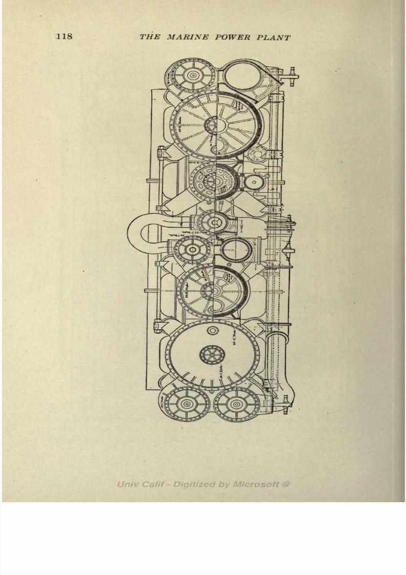
8/3/2019 Marine Power Plant Chaprich
http://slidepdf.com/reader/full/marine-power-plant-chaprich 130/335
118 THE MARINE POWER PLANT

8/3/2019 Marine Power Plant Chaprich
http://slidepdf.com/reader/full/marine-power-plant-chaprich 131/335
THE RECIPROCATING ENGINE 119
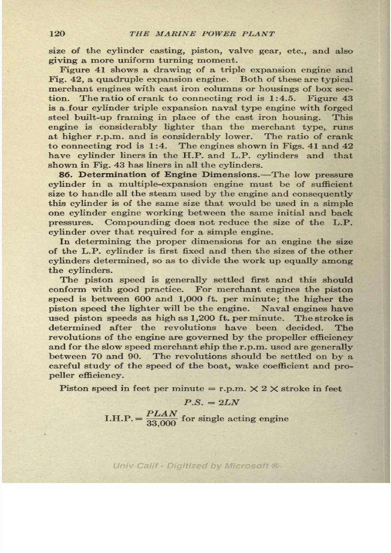
8/3/2019 Marine Power Plant Chaprich
http://slidepdf.com/reader/full/marine-power-plant-chaprich 132/335
120 THE MARINE POWER PLANT
size of the cylinder casting, piston, valve gear, etc., and also
giving a more uniform turning moment.
Figure 41 shows a drawing of a triple expansion engine andFig. 42, a quadruple expansion engine. Both of these are typical
merchant engines with cast iron columns or housings of box sec-
tion. The ratio of crank to connecting rod is 1:4.5. Figure 43
is a. four cylinder triple expansion naval type engine with forged
steel built-up framing in place of the cast iron housing. This
engine is considerably lighter than the merchant type,, runs
at higher r.p.m. and is considerably lower. The ratio of crank
to connecting rod is 1:4. The engines shown in Figs. 41 and 42
have cylinder liners in the H.P. and L.P. cylinders and that
shown in Fig. 43 has liners in all the cylinders.
86. Determination of Engine Dimensions. The low pressure
cylinder in a multiple-expansion engine must be of sufficient
size to handle all the steam used by the engine and consequently
this cylinder is of the same size that would be used in a simple
one cylinder engine working between the same initial and back
pressures. Compounding does not reduce the size of the L.P.
cylinder over that required for a simple engine.
In determining the proper dimensions for an engine the size
of the L.P. cylinder is first fixed and then the sizes of the other
cylinders determined, so as to divide the work up equally amongthe cylinders.
The piston speed is generally settled first and this should
conform with good practice. For merchant engines the piston
speed is between 600 and 1,000 ft. per minute; the higher the
piston speed the lighter will be the engine. Naval engines have
used piston speeds as high as 1,200 ft. per minute. The stroke is
determined after the revolutions have been decided. The
revolutions of the engine are governed by the propeller efficiency
and for the slow speed merchant ship the r.p.m. used are generally
between 70 and 90. The revolutions should be settled on by a
careful study of the speed of the boat, wake coefficient and pro-
peller efficiency.
Piston speed in feet per minute = r.p.m. X 2 X stroke in feet
P.S. = 2LN
PLAN ,I.H.P. = for single acting engine

8/3/2019 Marine Power Plant Chaprich
http://slidepdf.com/reader/full/marine-power-plant-chaprich 133/335
THE RECIPROCATING ENGINE 121
where P is the mean effective pressure acting on piston in pounds
per square inch.L the stroke in feet.
A the area of the L.P. cylinder in square inches.
N the revolutions per minute.
P.S. the piston speed.
For a double acting engine with steam acting on both sides of
the piston the I.H.P. becomes twice the above or
PX-4 XP $
I.H.P.
= ' - fordouble acting engine.oo,UUU
In working up the design of a multiple-expansion engine it is
assumed that all the work is done in the L.P. cylinder and hence
the "P" used in the above expressions is the m.e.p. (mean effec-
tive pressure) referred to the L.P. cylinder or as commonly written
m.r.p. (mean referred pressure) or r.m.e.p. This mean referred
pressure is used only in designing and is not the same as the
m.e.p.in the low
pressure cylinderof the actual
engine.It is
the m.e.p. that would result if all the expansion took place in
the L.P. cylinder instead a third or a fourth of the expansion as
is the actual case.
The theoretical mean referred pressure can be quickly obtained
when the initial pressure (Pi), the back pressure (P#), and the
ratio of expansion (R) have been settled upon. The ratio of
expansion is the number of times that the steam admitted
per stroke tothe
high pressure cylinder expandsin
volume.In other words it is the ratio of the volume of the H.P. cylinder
at cut-off to the volume of the L.P. cylinder. The proper ratio
of expansion to use can only be fixed after some knowledge
of engine design has been obtained by actual experience. Theo-
retically the higher the ratio of expansion used the higher will
be the thermal efficiency of the engine but other considerations
such as size, weight, and engine friction fix the ratio of expansion
that it is advisable to use. In naval vessels this ratio is lowerthan in merchant vessels in order to cut down the weight of the
engine and the size of the L.P. cylinder. (See Table IX.)
M.r.p. =A
x See HIRSHFELD & BARNARD, "Elements of Heat Power Engineering,"
for the derivation of this formula-

8/3/2019 Marine Power Plant Chaprich
http://slidepdf.com/reader/full/marine-power-plant-chaprich 134/335
122 THE MARINE POWER PLANT
The back pressure (PB) is the pressure existing in the L.P. cylinder
at exhaust and is somewhat higher than the pressure in the
condenser.The mean referred pressure found by the above formula is
the theoretical value that would be obtained for an expansion
between the limits of PI and PB under ideal conditions. Actu-
ally, the m.r.p. is much less than found by this expression due
US.S DELAWARE
COMBixto DIAGRAM
STOA
CARDS, SET No 4
M E P Rcrcmo TO l.PC'UNDCR- 5407
FIG. 44.
to cylinder condensation, leakage, transfer of steam from one
cylinder to another, wiredrawing, incomplete expansion and
clearance losses. The m.r.p. as found by above formula is
multiplied by a coefficient obtained from practice. This coef-
ficient is known as the "card effect" or "m.e.p. factor." Values
obtained from engine trials are given in Table IX. Figure 44
shows the theoretical and actual cards of the U. S. S. "Delaware"
from a paper by R. T. Hall in the Jour. A. S. N. E., 1909.

8/3/2019 Marine Power Plant Chaprich
http://slidepdf.com/reader/full/marine-power-plant-chaprich 135/335
THE RECIPROCATING ENGINE 123
After the area of the L.P. cylinder has been obtained the area
of the H.P. cylinder can be obtained from the ratio of expansion
after the cut off of that cylinder is decided on.
-P, ,. r . Volume of L.P. cylinder
Ratio of expansion=
^7-7 c ^ p ,. , aVolume of H.P. cylinderX per cent cut-off.
Corrections must be made for area of the piston rod and clear-
ance volumes as shown in the example in the following article.
The area of the intermediate piston is obtained from the L.P.
and H.P. by a ratio from practice so that the work done in each
cylinder is the same.
87. Example of Engine Design. Determine the dimensions of a three-
cylinder triple expansion engine for the following conditions:
I.H.P. =2,900
R.p.m.= 90
Boiler pressure= 210 Ibs. gage.
Pi (at throttle) =200 Ibs. gage.
Superheat at throttle = 60F.Vacuum in condenser (P2)=27 in. (1.46 Ibs./sq. in.).
Estimated steam consumption= 14.0 Ibs. per I.H.P. per hour.
Back pressure in engine cylinder (Pfl)=3.0 lbs./sq. in.
Ratio of expansions (R) assumed as 11.5 (Table IX).
Piston speed (assumed)= 900 ft. per min.
Theoretical referred m.e.p. =Pi(1+1 ge R) -pB
=(215 X.30) -3 = 61.5 lbs./sq. in.
Card effect or diagram factor = .55 (Table IX).
Actual referred m.e.p.= 61.5 X.55 = 33.8 lbs./sq. in.
I.H.P. X33.000 2,900 X33,000Net areaL.P.cylmder = __-_ =
3,140 sq. ft.
Diam. L.P. cylinder= 63J in.
H.P. cut-off (assumed)= .70
H.P. clearance (assumed) = 15 per cent.
L.P. clearance = 10 per cent.
Piston rod diameter (assumed) =5 in.
..Ratio of expansion
=(2^_ p>r>) (H<?+ft)
where
AL = L.P. cylinder area.
AH H.P. cylinder area.
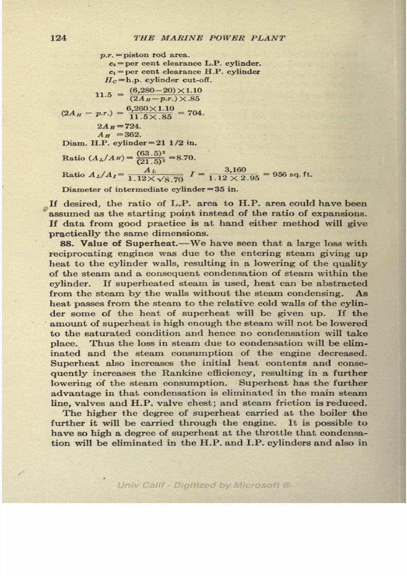
8/3/2019 Marine Power Plant Chaprich
http://slidepdf.com/reader/full/marine-power-plant-chaprich 136/335
124 THE MARINE POWER PLANT
p.r.=piston rod area.
Cz=per cent clearance L.P. cylinder,
ci=per
cent clearance H.P.cylinder#c =h.p. cylinder cut-off.
(6,280-20) X 1.1011.5 =
(2AH -p.r.)X.85
, 6,260X1.10 ,_.,(2AH -p.r.}=
-
=704.
= 724.
An =362.
Diam. H.P. cylinder= 21 1/2 in.
Ratio Uft/4')- 2Jj=8.70.
Ratio AjAr * =1.12
3
X
6
2.95= 956 sq ' ft '
Diameter of intermediate cylinder= 35 in.
,If desired, the ratio of L.P. area to H.P. area could have been*
assumed as the starting point instead of the ratio of expansions.
Ifdata
fromgood practice
is at hand either method willgive
practically the same dimensions.
88. Value of Superheat. We have seen that a large loss with
reciprocating engines was due to the entering steam giving up
heat to the cylinder walls, resulting in a lowering of the quality
of the steam and a consequent condensation of steam within the
cylinder. If superheated steam is used, heat can be abstracted
from the steam by the walls without the steam condensing. As
heat passes from the steam to the relative cold walls of the cylin-
der some of the heat of superheat will be given up. If the
amount of superheat is high enough the steam will not be lowered
to the saturated condition and hence no condensation will take
place. Thus the loss in steam due to condensation will be elim-
inated and the steam consumption of the engine decreased.
Superheat also increases the initial heat contents and conse-
quently increases the Rankine efficiency, resulting in a further
lowering of the steam consumption. Superheat has the further
advantage in that condensation is eliminated in the main steam
line, valves and H.P. valve chest; and steam friction is reduced.
The higher the degree of superheat carried at the boiler the
further it will be carried through the engine. It is possible to
have so high a degree of superheat at the throttle that condensa-
tion will be eliminated in the H.P. and I.P. cylinders and also in

8/3/2019 Marine Power Plant Chaprich
http://slidepdf.com/reader/full/marine-power-plant-chaprich 137/335
THE RECIPROCATING ENGINE 125
the L.P. cylinder up to the point of cut-off. Thus with 160 Ibs.
gageinitial
pressure and 250of
superheatan adiabatic
expansionwill not cross the dry steam line until it is reduced to about 15 Ibs.
gage. A superheat as high as this of course will greatly reduce
the steam consumption and prevent loss due to condensation and
leakage in all three cylinders, valves and receivers. With proper
lagging radiation losses need be no higher than with dry steam.
However, superheat may be carried so high that the cost of
producing it plus the greater first cost and maintenance charges
will offset the reduction in steam consumption. Neither steamnor fuel consumption is the true criterion for measuring the gain.
The gain should be measured in reduced fuel costs minus in-
creased capital and maintenance charges. Condensation in
the L.P. cylinder and valve chest can be kept under control
without superheat by using reheaters and steam jackets.
When using superheated steam, lubricating oil must be intro-
duced into the cylinders to lubricate the cylinder walls. This
requires special attention to the extraction of oil from the feedwater a problem not present when superheat is used with
turbines nor when saturated steam is used. Further, high
superheat requires special attention to valves and ports and
passage because of the erosive effect of superheated steam.
The volume occupied by a pound of steam increases as the degree
of superheat is increased, consequently a larger size cylinder will
have to be fitted when superheated steam is used. This may
result in a slightly increased first cost of the engine.
Gray (I. N. A., 1914) advocates theuseof 180 to 200 superheat
with triple and quadruple expansion engines in order to carry
dry steam through the L.P. valve chest. He quotes cases where
a reduction in coal consumption and a consequent gain in cargo
space have saved the cost of the superheater the first year. Cer-
tainly the losses in reciprocating engines in the past due to cylin-
der condensation and leakage around valve rods, valves and
piston rods have been very large and if superheat will eliminate
these losses that in itself is enough to recommend it. Gray
states a case where the leakage around the I.P. and L.P. valve
chest was 20 gallons per hour. Superheat as high as 200 with
its additional costs, increased size of engine, and complications,
hardly seems advisable at the present day, despite the gain
anticipated.

8/3/2019 Marine Power Plant Chaprich
http://slidepdf.com/reader/full/marine-power-plant-chaprich 138/335
126 THE MARINE POWER PLANT
The last ships in the U. S. Navy fitted with reciprocating
engines carried between 50 and 80 of superheat and showed
marked decrease in fuel consumption over the ships not using
superheat. This amount of superheat eliminates condensation
in the H.P. cylinder and yet is not high enough to cause troubles
due to high temperatures. Speaking of these ships in the
Jour. American Society of Naval Engineers, May, 1914, H. C.
.Dinger states:
"The experience with superheaters on B & W boilers in the navy in
connection with the latest designs of reciprocating, engines has been en-
tirely satisfactory. The superheaters have given no trouble and have
required practically no repairs. No more difficulty as to internal lubri-
cation has been experienced with superheat than there has been with-
out it."
In view of what has been stated it seems advisable to use
about 60 of superheat with reciprocating engines. With this
amount an appreciable reduction in the steam consumption will
result, internal lubrication will not be necessary and condensation
and leakage can be eliminated in the main steam line, and H.P.
chest and cylinder. This degree of superheat also allows the
use of Scotch boilers with the waste iype superheater. This
amount of superheat will give dry steam at cut-off.
A noteworthy example of superheated steam with reciprocating
engines is the Lehigh Valley R. R. Tug "Lehigh."1 This boat
is fitted with triple expansion engines and Scotch boilers. Theboilers are equipped with fire tube superheaters that give between
200 and 250F. superheat at the throttle. The horsepower of
the engines was increased 27 per cent and the economy increased
17 per cent by the use of this amount of superheat. Data for
this installation with and without superheat are given in Table
IX. Superheat has been used on this boat and other boats of
the same company for over four years and they have proved
very satisfactory and practically no outlay has been necessary
for maintenance. Lubricating oil is supplied to the cylinders
at the rate of 1 quart in 60 hours. The temperature at the base
of the stack was reduced from 527 to 385F. a very creditable
performance with Scotch boilers.
1 Marine Engineering & Shipping Age, Feb., 1922.

8/3/2019 Marine Power Plant Chaprich
http://slidepdf.com/reader/full/marine-power-plant-chaprich 139/335
THE RECIPROCATING ENGINE 127
89. Initial Steam Pressure. In Art. 13 it is shown that the
theoretical steam consumption of an engine is
2,545
~#i-#2
where Hi = the initial heat contents.
#2 = the final heat contents after an adiabatic expansion.
The lower we can reduce this theoretical consumption by in-
creasing HI the lower will be the steam consumption of the actual
engine. A study of the Mollier diagram or the steam tables
will show that H\ can be increased both by increasing the pressure
and by increasing the superheat. The Mollier diagram also
clearly shows that HI can be increased more rapidly by increasing
the degree of superheat than by increasing the steam pressure.
Thus increasing the pressure from 275 Ibs. absolute to 500 Ibs.
absolute (dry steam) increases HI from 1,202.8 b.t.u. to 1,210
b.t.u. a gain of 7.2 b.t.u. The same increase in b.t.u. could
be obtained by keeping the pressure at 275 Ibs. abs. and adding
only 9 of superheat. It will be seen that as far as initial heat
contents are concerned, increase in steam pressure over wide
ranges influences the initial heat contents HI very little.
There is a large gain, however, in the heat available for doing
work or "heat availability" by increasing the initial pressure.
Increasing the steam pressure lowers the entropy of the steam
and gives a lowerquality
(x2) at exhaust. Thus more heat is
converted into useful work and less rejected in the exhaust.
The work done per pound of steam = (ziri+gi #2) awBy increasing the steam pressure, x% is decreased for a given
back pressure and hence the heat rejected (x?r) is less. An
example will make this clear.
Case 1 Case 2
Pi = 500 at superheat PI *= 275 Ibs. at 9 superheat
P2= 28.83 in. (.575 Ib./sq. in.) P2= .575 Ib./sq. in.
<i= 467.3 2
= 418.5
Hi = 1,210 Hi = 1,210
#, = 797 S = .712 #a= 830 (Mollier) * = -745
= 1.47 = 1.53
tfi-#2=l,210-797 = 413 b.t.u. #i-#2
=1,210-830 = 380 b.t.u.
9 54.5 9 545wt=^if =6.17 lbs./s.h.p. hour wt=fr^7 <= 6 -7 Ibs./s.h.p.

8/3/2019 Marine Power Plant Chaprich
http://slidepdf.com/reader/full/marine-power-plant-chaprich 140/335
128 THE MARINE POWER PLANT
The initial heat contents (Hi) is the same in each case. In Case 1 the
steam pressure is 500 lbs./sq. in., while in Case 2 the pressure is 275 Ibs.
per sq. in. with sufficient superheat (9) to give the same initial heat contents
as Case 1. The quality (z2) in Case 1 after an adiabatic expansion to 28.83
in. vacuum is .712, while, in Case 2, z 2= .745. The result is that Hi in Case 1
is 797 and, in Case 2, 830. The steam consumption in Case 1 is consequently
0.53 Ib. (8.6 per cent) less than in Case 2.
It should also be noticed that the entropy for Case 1 is less than in Case
2, the higher "heat availability" being associated with a lower entropy.
The results of the foregoing cases are very clearly brought out on Mollier
and T<j> diagrams. By drawing out the two cases on the T<f> diagram it will
be observed that the area representing the heat rejected is greater in the
second case than in the first.
While superheat increases HI more rapidly than by increas-
ing the steam pressure it also decreases "heat availability";
increase in steam pressure, however, increases both HI and
"heat availability."
Pressures as high as 500 Ibs. are of course not feasible today,
and further we have already seen that superheat has many ad-
vantages not possible with high steam pressure. The purposeof the above discussion is to point out the gain due to high pres-
sures that is often overlooked. For high economy both high
pressures and moderate superheat are advisable.
Wire drawing or throttling is a constant heat change, the heat
contents being the same after throttling as before. But due to
the lower pressure the entropy is increased, the steam is super-
heated but the "heat availability" is reduced, resulting in less
heat being converted into useful work and greater heat entering
the condenser.
90. Vacuum. From our expression for theoretical steam con-
sumption it is apparent that a low vacuum will give a low value
of (#2) and hence reduce the steam consumption. While a
vacuum of slightly over 29 in. is possible, practical considera-
tions outweigh the theoretical gain expected. A vacuum can-
not be produced without the expenditure of power and if the
vacuum is carried too high the cost of producing it will offset
the gain in economy and horsepower obtained.
A study of the pressures and volumes of steam at low pres-
sures will show that the volume increases rapidly as the
pressure decreases. Thus, the volume of 1 Ib. of dry steam at
28 in. vacuum is practically double what it is at 26 in., and the
volume at 29 in. is nearly double that at 28 in. These large

8/3/2019 Marine Power Plant Chaprich
http://slidepdf.com/reader/full/marine-power-plant-chaprich 141/335
THE RECIPROCATING ENGINE 129
increases in steam volume can be easily taken care of in a tur-
bine;
but with areciprocating engine they
call for alarge
in-
crease in the size of the L.P. cylinder and valves. This not only
increases the size and first cost of the engine but also increases
the area of the cylinder walls and offers greater opportunity for
condensation. Further, the increased size of the cylinder, piston,
and valves greatly increases the friction of the mechanism. The
vacuum can be carried so high that the increase in friction in
the L.P. cylinder is greater than the gain in power due to the
highervacuum.
The above facts, together with the increased power and size
required for the air and circulating pumps, and greater danger
of air leakage show at once that a high vacuum is not desirable
with a reciprocating engine.
High vacua are often advocated for reciprocating engines and
trials are quoted to show the reduction in steam consumption.
First costs and cost of producing the higher vacuum are seldom
mentioned however. Probably 27 in. or possible 27 1/2 in. asa maximum can be carried to advantage in the condenser. This
will give 25 1/2 to 26 1/2 in. in the L.P. cylinder exhaust
ports. Even with these vacua, careful attention must be given
to the L.P. valve and steam passages to be sure that they are of
sufficient size to take care of the large volumes of steam.
Too little attention has been given to vacuum for merchant
ships and vacua around 21 or 22 in. are altogether too com-
mon. If proper attention is given to air pump capacity, air
leakage, valve and steam port design, a considerable gain in
economy and horsepower could be obtained by carrying a
higher vacuum.
Operating engineers at times, in ignorance of the gain due to
vacuum, decrease the vacuum in order to increase the tempera-
ture in the feed tank. Proper attention to the design of feed
heating system would obviate this bad practice.
91. Methods of Increasing Economy. In the engines for thelast U. S. battleships using reciprocating engines this type of
prime mover reached its highest state of development. Some
of the means adopted to improve the economy of these engines
are given below.
1. Forced lubrication.
2. Increased vacuum (27 in.) over merchant practice.

8/3/2019 Marine Power Plant Chaprich
http://slidepdf.com/reader/full/marine-power-plant-chaprich 142/335
130 MARINE POWER PLANT
aad'^5

8/3/2019 Marine Power Plant Chaprich
http://slidepdf.com/reader/full/marine-power-plant-chaprich 143/335
THE RECIPROCATING ENGINE 131
3. Moderate degree of superheat (60).
4. Large and straight H. P. valve passages by the use of piston valves
(resulting in reduction in steam velocities and hence less drop in pressure).
5. Reduction in cylinder clearances.
6. Steam jackets introduced on L.P. cylinder walls and ends (to reduce
condensation).
7. Double piston valves on L.P. cylinder.
8. Steam seal on L.P. piston rod (eliminating air leakage, water leakage
and entrance of oil into cylinder).
9. Four cylinder triple in place of quadruple expansion engine with its
large L.P. cylinder.
10. Increased size of L.P. valve ports.11. Reheaters fitted (to reduce condensation).
Assisting steam cylinders are often fitted on the intermediate
and low pressure valve rods to reduce the friction load on the
valve gear due to the heavy valves. Figure 42 shows an engine
fitted with assisting cylinders.
For details of reciprocating engines, engine design and valve gears, the
reader is referred to the following books and papers:
STERLING, "Marine Engineers' Handbook."
PEABODY,"Computations for Marine Engineers."
BRAGG, "Design of Marine Engines and Auxiliaries."
E. H. JANSON, "The Naval Reciprocating Steam Engine, Its Character-
istics, Dimensions and Economics." Jour. A. S. N. E., Feb., 1912.

8/3/2019 Marine Power Plant Chaprich
http://slidepdf.com/reader/full/marine-power-plant-chaprich 144/335
CHAPTER X
THE STEAM TURBINE
The elementary principle of the steam turbine consists in
converting the potential heat energy of the steam into kinetic
energy by expanding it through a nozzle. The steam leavingthe nozzle at high velocity is directed against the buckets of a
wheel which rotates due to the impinging action of the jet and
the kinetic energy of the steam is converted into mechanical
work.
92. The Flow of Steam. When steam under pressure is at
rest its energy is potential and is in the form of heat. Thus,
the potential energy of a pound of steam confined in a vessel
under a pressure of PI Ibs. per sq. in. is its total heat contents,
This potential heat energy is measured above the established
datum of 32F. If the vessel containing this steam is opened
up to the atmosphere or another vessel at lower pressure, flow
will take place from the higher to the lower pressure and part
of the potential energy in the form of heat contents will be
converted into kinetic energy or velocity.
Consider the vessel in Fig. 45.
Neglecting friction, we can say that
/> / L-7
the sum of the potential and kinetic
energies at (1) are equal to the sum
of the potential energies at (2). The
FIG. 45. total
energyat
(1)must
equalthe
total energy at (2), provided there
is no loss, by the law of conservation of energy. We can now
set up an energy equation between points (1) and (2),
WVi778
"7" '
132

8/3/2019 Marine Power Plant Chaprich
http://slidepdf.com/reader/full/marine-power-plant-chaprich 145/335
THE STEAM TURBINE 133
where HI and #2 are the heat contents at points (1) and (2)
WVi
2
WV2
2
in b.t.u. per lb., -~ and ~ are the kinetic energy at points
(1) and (2) in ft. Ibs. and W is the weight of steam present in
the vessel. By multiplying the heat contents by 778 all the
terms are reduced to a common basis of foot-pounds.1
Students of hydraulics will observe that by cancelling out the
Ws, the above equation is similar in form to the Bernouilli
equation with the term for gravity head omitted. In practi-
callyall cases
involvingthe flow of
steam,the difference in ele-
vation of two points can be neglected.
If we consider that the pressure at (2) is lower than at (1),
flow will take place from (1) to (2). In nearly all cases we can
consider that the steam in the initial condition at point (1) is
at rest; hence Fi = 0. Cancelling the W common to all terms
and placing V\ = we have
The velocity of the steam at point (2) in feet per second is,
where HI is the initial heat contents at pressure PI and H2 is
the final heat contents after expansion from PI to PZ.
93. Expansion of Steam through Nozzles. In steam turbines
the steam is expanded from pressure PI to pressure P2 in a nozzle,
Fig. 46. The expansion is
rapid and there is practically
no transfer of heat between FlGi 46._steam nozzle.
the sides of the nozzle and the
steam. Hence, as this is an expansion without heat being received
or rejected, the velocity must be created (i.e., work done) by the
heat in thesteam,
and theexpansion
must be adiabatic. This
expansion is an irreversible adiabatic and is not necessarily
isentropic.
In Art. 10 one form of adiabatic expansion was discussed,
i.e., throttling of steam, in which entropy increased; in fact the
1 The term 778 WH\ is in ft. Ibs. for H\ is expressed in b.t.u. per lb. and
W is in pounds; hence WH\ must be in b.t.u. and 778 WH\ in ft. Ibs.

8/3/2019 Marine Power Plant Chaprich
http://slidepdf.com/reader/full/marine-power-plant-chaprich 146/335
134 THE MARINE POWER PLANT
expansion line of the Mollier diagram crossed the lines of con-
stant entropy at right angles. This expansion at constant heat
contents (work = 0) is represented on the !F0 diagram, Fig. 47, byline 14. Line 1-2 represents the isentropic adiabatic expansion
in the cylinder of a steam engine where work done = 'i E%.
Experiments show that the adiabatic expansions of steam in
a nozzle is along a line 13 and very nearly isentropic. Due to
friction of the steam on the sides of the nozzle the heat contents
and the quality of the steam at the end of the expansion are
slightly higher than after a expansion (12) at constant entropy.
f
FIG. 47.
In all problems involving the flow of steam, the expansion are
assumed to take place at constant entropy and a correction
factor is used to correct for the final heat contents and quality.
The factor y is used to represent the percentage of the available
heat (Hi HZ) that is used in overcoming friction and hence
represents the percentage of loss. The factor (1 y), therefore,
represents the percentage of the available heat that is converted
into kinetic energy. Hence, the actual velocity of steam issuing
from a nozzle is,
The factor y is fairly well determined from experiments and ranges
between .05 and .10.
The percentage y of the available heat is not lost by radiation
through the walls of the nozzle but is used in overcoming friction

8/3/2019 Marine Power Plant Chaprich
http://slidepdf.com/reader/full/marine-power-plant-chaprich 147/335
THE STEAM TURBINE 135
and is returned to the steam in the form of heat. It appears in
the steam at point 3 in the form of increased heat contents.
We thus see that the frictional resistance offered by a nozzle
decreases the velocity of the steam and increases the final heat
contents (#2), quality, and entropy of the steam at the end of
the expansion.
94. Ideal or Theoretical (Rankine) Efficiency. In the ideal
nozzle there would be no friction, the expansion would be isen-
tropic and the velocity would be,
V =223.8VHI - H2 ft. per second.
Thus HI Hz b.t.u. per Ib. of steam would be converted into
useful work, the same as in the theoretical steam engine.
The expressions developed for the theoretical Rankine cycle
of the steam engine (Arts. 11 to 17) apply to the steam turbine
also.
IT ITTheoretical efficiency
=y/r/i q2
2 545Steam consumption of ideal turbine Wt
I H2
Thermal efficiency of actual turbine = ^' *-
^
W t
Efficiency Ratio = T==-
rr a
95. Thermodynamics of the Steam Turbine. Figure 48 shows
the T(f> diagram of the actual turbine. Area 12-3-4-5 repre-
sents the heat received (Hi q2); area 5-674 represents the
heat rejected (z2r 2), where z2 represents the quality at point 6
instead of at point 8 as in the ideal case. The heat rejected in
the theoretical cycle is area 8-3-4~5. As more heat is rejected in
the actual cycle than in the theoretical, less heat is convertedinto work. The heat converted into work is not represented by
any area on the diagram but is equal to area (1-2-3-4-5) area
(5-6-7-4) - This is equivalent to area (1-2-8-5)- area (8-6-7-3) .
In the foregoing discussion, the turbine has been considered
as a simple case of a single nozzle and one revolving wheel.
The difference between the energy at entrance and exit of the

8/3/2019 Marine Power Plant Chaprich
http://slidepdf.com/reader/full/marine-power-plant-chaprich 148/335
136 THE MARINE POWER PLANT
nozzle, (Hi H2) (1 y),has been converted into useful mechanical
work on the turbine shaft. Actual turbines consist of a com-
bination of many nozzles, revolving wheels and stages, but the
principles and theoretical equations given above will hold for
iL
4<f
J 7
FIG. 48. T<f> Diagram of the steam turbine.
the compound turbine as well as the simple turbine. The
point 1 always represents the condition at the turbine throttle
and 2 the condition in the condenser.
Example. Calculate the theoretical and actual velocity of steam ex-
panded in a nozzle from dry steam at 200 Ibs. abs. to atmospheric pressure,
friction factor (y)= .08.
Theoretical velocity= 223.8\/Hi-Hz
Actual velocity= 223.8V(#i -#2)X .92
From the Mollier diagram Hi for dry steam at 200 Ibs. =1,198 b.t.u.
Ht after adiabatic expansion (0=
1.545) at 14.7 Ibs. =1,010 b.t.u.
Hi-H2= "188 b.t.u.
V t-= 224Xx/188 = 3,070 ft. per sec.
Fa = 224X\/173 t=2,945 ft. per sec.
z 2= .855 (see T<t> diagram, Fig. 47).
The heat contents (#0 after an actual expansion in a nozzle with y =
.08 is,
H t=
1,198 -173 = 1,025
where
173 = (Hi Hi) (1 y), the heat converted into work.
Therefore, x zrt +92=
1,025
where x 8 is the actual quality of the steam.

8/3/2019 Marine Power Plant Chaprich
http://slidepdf.com/reader/full/marine-power-plant-chaprich 149/335
THE STEAM TURBINE 137
Solving for xt we have,
= i?.5
Jliz
= 1,025-180r, 970.3
z 8= .871 (see T<f> diagram, Fig. 47).
The quality x 3 can also be obtained from the Mollier diagram at P 8-
14.7,
and heat contents = 1,025.
xt after a pure adiabatic expansion, is .855
It will be observed that in obtaining actual velocity, theoretical steam
consumption, etc., the value of x 3 is not required; H t is obtained as if the
expansion were adiabatic, and (Hi H 2) is corrected by (1 y) as shown in
the above example.
96. Steam Nozzles. If steam is to be expanded adiabatically
from a high to a low pressure without irregular action, loss and
dissipation of energy, a nozzle must be used in which the areas
of the cross sections are made proportional to the changes in
the volume of the steam during its reduction in pressure. As
the heat contents of the steam is converted into velocity along
the nozzle, the pressure of the steam drops and the volume and
velocity increase. Thus we have three variables to determine
in fixing the areas of the sections of the nozzle.
From the fundamental equation of hydraulics, Q = av, we have
for the area of the nozzle in square inches,
Q 144 w.s.x.=
v= ^r
where 8 =the volume of one Ib. of steam in cu. ft.
x =the quality.
V = the velocity of the steam in feet per sec.
w = the number of Ibs. of steam flowing per sec.
Both analytical and experimental investigations show that
the area of the nozzles reaches a minimum at a pressure equal
to .58 of the initial pressure and then increases gradually again
to the point of exit. Thus the area of the cross section will bea minimum for P2
= .58Pi. The nozzle will first converge and
then diverge as shown by Fig. 46.
A correctly designed nozzle will have a curved contour from
entrance to exit. This curve from throat to exit is so nearly a
straight line that it is the universal practice, for the sake of
simplicity in construction, to give the nozzle a straight taper

8/3/2019 Marine Power Plant Chaprich
http://slidepdf.com/reader/full/marine-power-plant-chaprich 150/335
138 THE MARINE POWER PLANT
from throat to exit. The area at entrance is indeterminate.
Figure 46 shows a typical turbine nozzle. It is given a round-
ingcurve from entrance to
throat,a
straight taperfrom throat
to exit, and a cylindrical guide section between the exit and the
wheel. The length is obtained by using a taper of 1 : 5 to
1 : 12 from throat to exit and a small, additional length from
throat to entrance. The sections of the nozzle in practice are
made both square and circular.
97. Nozzle Design. The method of designing a nozzle is
illustrated by the following example:
Determine the areas at throat and exit for a nozzle to expand 1,800
Ibs. of steam per hour from 200 Ibs. abs. to 2 Ibs. abs.
y-.10.
Pi = 200 Ibs. (entrance).
P2= .58Pi = 116 Ibs. (throat).
P3= 2.0 Ibs. (exit).
W =1,800 -r-3,600
= 0.5 Ib. per sec.
#i = l,198.
#2 = 1,147 (Mollier diagram).= 1.545.
# 3 = 898 (Mollier diagram).
zi= 1.00.
x2= .956.
z s= .787.
Fi-0.
2= 224 Vl,198 =
1,147=
1,600 ft. per sec.
8=224-^(1,198
-898) .90 = 3,680 ft. per sec.
Hi* actual quality at 3 =
1,198- 270 - 94
1,021.9
From the Mollier diagram at P 3= 2 Ibe.and heat contents -(1,198 270)
928,
24=
.815, which is more readily obtained than by the above method.
XiSi = 1.00X2.288 = 2.29 cu. ft.
x 2sz=
.956X3.844 = 3.68 cu. ft.
z 4s 3= .815X173.1 = 141.00 cu. ft.
02= _ .
.166 sq . in .
144 X 141 X .5

8/3/2019 Marine Power Plant Chaprich
http://slidepdf.com/reader/full/marine-power-plant-chaprich 151/335
THE STEAM TURBINE 139
98. The Dynamics of the Steam Turbine. Figure 49 shows
the velocity diagram for a simple impulse turbine, with thesteam entering horizontally.
Vi = absolute velocity of the steam leaving nozzle.
u =peripheral velocity of blade.
Vi= relative velocity of steam entering blading.
Vz= relative velocity of steam leaving blading.
Vz= absolute velocity of steam leaving blading.
a angle of jet with direction of motion.
The steam leaves the nozzle at angle a to the direction of
motion with a velocity of Vi feet per second and the blades are
assumed to be moving with a linear velocity of u ft. per second.
Under these conditions the relative velocity of the steam jet
with respect to the wheel is Vi, as shown in Fig. 49. In order
FIG. 49. Velocity diagram of simple turbine.
that the steam may enter the blade without spattering, the
blade should be made tangent to v\. The steam is reversed in
direction and leaves the wheel with the relative velocity Vz.
Much higher efficiency could be obtained if the steam entered
and left the blades in the same line of direction with which the
blades are moving and with a velocity equal to twice that of
the blade. Under these conditions Vz would be equal to zero
and the maximum possible efficiency would be attained. Such
an arrangement could not be used in practice because of the
interference of the jet and blades, hence the steam must enter
and leave at an angle a to the blades as shown in Fig. 49.
The absolute velocity V\ can be resolved into two components
as shown in Fig. 49 where db=V\ cos a represents the useful
velocity causing rotation and ac = V\ sin a causing end thrust
along the shaft. In order to make ab large and ac small the
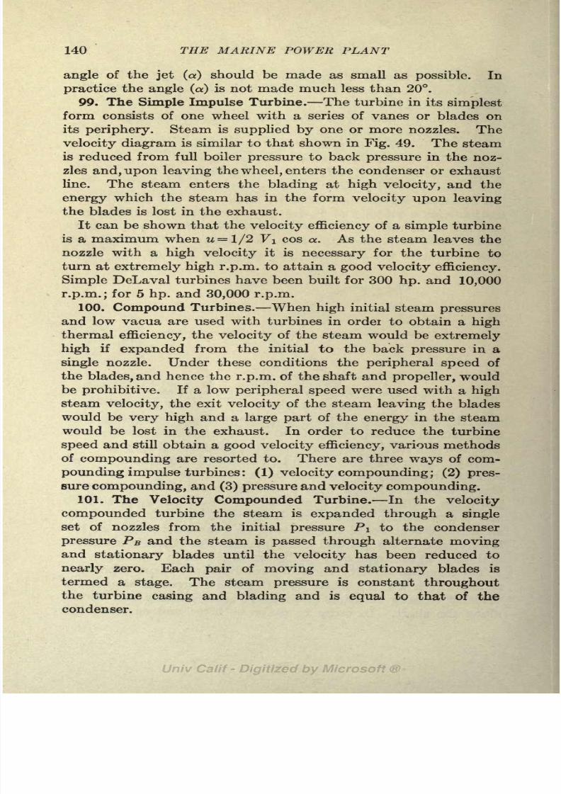
8/3/2019 Marine Power Plant Chaprich
http://slidepdf.com/reader/full/marine-power-plant-chaprich 152/335
140 THE MARINE POWER PLANT
angle of the jet (a) should be made as small as possible. In
practice the angle (a) is not made much less than 20.
99. The Simple Impulse Turbine. The turbine in its simplest
form consists of one wheel with a series of vanes or blades on
its periphery. Steam is supplied by one or more nozzles. The
velocity diagram is similar to that shown in Fig. 49. The steam
is reduced from full boiler pressure to back pressure in the noz-
zles and, upon leaving the wheel, enters the condenser or exhaust
line. The steam enters the blading at high velocity, and the
energy which the steam has in the form velocity upon leaving
the blades is lost in the exhaust.
It can be shown that the velocity efficiency of a simple turbine
is a maximum when u= l/2 V\ cos a. As the steam leaves the
nozzle with a high velocity it is necessary for the turbine to
turn at extremely high r.p.m. to attain a good velocity efficiency.
Simple DeLaval turbines have been built for 300 hp. and 10,000
r.p.m.; for 5 hp. and 30,000 r.p.m.
100.
CompoundTurbines. When
highinitial steam
pressuresand low vacua are used with turbines in order to obtain a high
thermal efficiency, the velocity of the steam would be extremely
high if expanded from the initial to the back pressure in a
single nozzle. Under these conditions the peripheral speed of
the blades, and hence the r.p.m. of the shaft and propeller, would
be prohibitive. If a low peripheral speed were used with a high
steam velocity, the exit velocity of the steam leaving the blades
would be very high and a large part of the energy in the steamwould be lost in the exhaust. In order to reduce the turbine
speed and still obtain a good velocity efficiency, various methods
of compounding are resorted to. There are three ways of com-
pounding impulse turbines : (1) velocity compounding; (2) pres-
sure compounding, and (3) pressure and velocity compounding.
101. The Velocity Compounded Turbine. In the velocity
compounded turbine the steam is expanded through a single
set of nozzles from the initial pressure PI to the condenser
pressure PB and the steam is passed through alternate movingand stationary blades until the velocity has been reduced to
nearly zero. Each pair of moving and stationary blades is
termed a stage. The steam pressure is constant throughout
the turbine casing and blading and is equal to that of the
condenser.

8/3/2019 Marine Power Plant Chaprich
http://slidepdf.com/reader/full/marine-power-plant-chaprich 153/335
THE STEAM TURBINE 141
As the steam passes through the first row of moving blades
partof its kinetic
energyis converted into mechanical work
and the steam leaves with less velocity than it had at entrance.
Upon leaving the first row of moving blades the steam enters
a row of stationary blades. These serve merely to reverse the
direction of the steam and, neglecting friction, there is no change
in velocity as the steam passes through these blades. The steam
next enters the second row of moving blades, where its velocity
is still further reduced.
Figure 50shows a
velocity diagramof a two
stage velocitycompounded turbine. It will be observed that the blade velo-
city (u) is constant for all mov-
ing vanes and is small com-
pared to the velocity (Yi) of
the steam leaving the nozzle.
The velocity is reduced in each
stage until it has the absolute
velocity of Vt at exit of thelast stage. A small DeLaval
velocitypcompounded turbine
is shown in Fig. 51.
The velocity diagrams, Figs.
50 and 49, are drawn for the
theoretical case when no fric-
tion exists. In the actual tur-
bine the friction of the steam
crossing the moving and sta-
tionary blades materially cuts
down the exit velocity from the
blades over that shown in Fig.
50. The effect of blade friction is to increase the heat contents
of the steam as was described under nozzle design, and to make tur-
bine design more complicated than the elementary case given here.
102. The Pressure Compounded Turbine. In the pressure
compounded turbine the steam passes successively through
nozzles and moving vanes until the pressure of the steam has
been reduced to that of the condenser. The nozzles are designed
so that there is only a small drop in pressure and hence the veloc-
ity of the steam at the exit of the nozzles is small. The energy
of the steam on leaving the first set of nozzles is partly kinetic
FIG. 50. Diagram of velocity
compounded turbine.
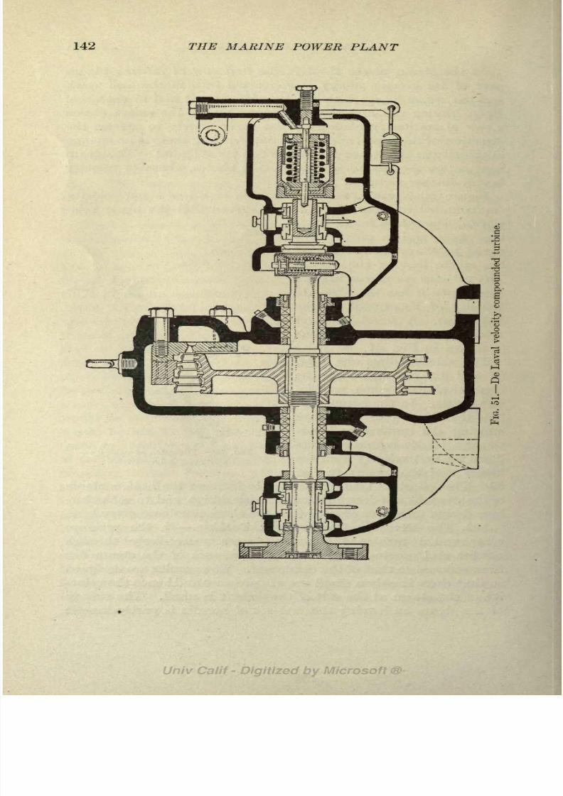
8/3/2019 Marine Power Plant Chaprich
http://slidepdf.com/reader/full/marine-power-plant-chaprich 154/335
142 THE MARINE POWER PLANT

8/3/2019 Marine Power Plant Chaprich
http://slidepdf.com/reader/full/marine-power-plant-chaprich 155/335
THE STEAM TURBINE 143
(velocity) and partly potential (heat contents). The heat con-
tents remainingin
the steamis
usedin
creating velocityin the
remaining nozzles. Figure 52 shows a seven stage pressure
compounded turbine. The pressure compounded turbine has
but one row of moving blades per stage and the pressure varies
from stage to stage. All the velocity acquired in the first set
of nozzles is converted into mechanical work in the first row of
moving blades. After leaving the first row of blades the steam
enters a second set of nozzles where the velocity is again increased
by a drop in pressure through the nozzles. As the steam in-

8/3/2019 Marine Power Plant Chaprich
http://slidepdf.com/reader/full/marine-power-plant-chaprich 156/335
144 THE MARINE POWER PLANT

8/3/2019 Marine Power Plant Chaprich
http://slidepdf.com/reader/full/marine-power-plant-chaprich 157/335
THE STEAM TURBINE 145
creases in volume with a reduction in pressure, the area through
the nozzles and blades must increase fromstage
as shown in
Fig. 52. As the pressure in each stage is different from that in
From Boiler
Through Steam
Strainer;
Emergency Valve,
and Ahead
Maneuvering Valve
To Steam Chest.
FIG. 53a. Diagram of velocity-pressure compounded turbine
(General Electric Co.).
the adjacent ones, each stage must be made steam tight in
order to avoid leakage. This is accomplished by extending the
diaphragm which holds the nozzles in to the shaft. As the cir-
cumference at the shaft is much less than it would be at the

8/3/2019 Marine Power Plant Chaprich
http://slidepdf.com/reader/full/marine-power-plant-chaprich 158/335
146 THE MARINE POWER PLANT
nozzles, a tight joint is more easily made between the moving
shaft and stationary diaphragm than would be possible if an
attempt were made to keep a tight joint close to the nozzles.
This method of securing steam tightness between stages results
in the disc type of construction shown in Fig. 52.
For a turbine of (n) stages the heat available per stage is
TT TT
--, where Hi is the heat contents at the initial pressure Pi
FIG. 54. Cylinder cover. L. P. unit. Westinghouse turbine.
and Hz the heat contents after an expansion to the condenser
pressure PB> The velocity at entrance to each stage is
7=
103. Pressure Velocity Compounded Turbine. This type of
turbine is a combination of the two previously discussed. It
consists of a number of pressure stages with several moving
(velocity compounded) wheels in each stage. A turbine of this
type is used where a large reduction is desired between the steam
and blade velocity. Figure 53 shows a turbine with a velocity

8/3/2019 Marine Power Plant Chaprich
http://slidepdf.com/reader/full/marine-power-plant-chaprich 159/335
THE STEAM TURBINE 147
compounded wheel in the first stage and the rest of the stages
pure pressure compounded.Figure 53a shows a diagram of the General Electric Co., Curtis
type turbine (See Figs. 53 and 57). This turbine is of the pres-
sure-velocity compound type. The first stage is velocity com-
pounded. The steam enters through the nozzles at C and
passes through two sets of moving blades, E and G, and one row of
stationary blades F. The four remaining stages are of the pres-
sure compounded type. It will be noticed that the nozzles are
converging, which is always the case when the exit pressure is
FIG. 65. H. P. cylinder base Westinghouse turbine.
greater than .58 PI. Figures 53a and 57 show clearly the disc
construction of impulse turbine.
104. The Parsons Reaction Turbine. The Parsons turbine
uses both the impulse and reaction of the steam in doing work.
The turbine consists of a large number of alternate moving and
stationary rings
of
blading.
No nozzles are used.
The steam upon leaving the throttle passes through an annular
set of stationary vanes attached to the turbine casing. These
blades are constructed so that the area at exit between two
adjacent blades is smaller than at entrance. This causes a drop
in pressure and an increase in the velocity of the steam, the same
as in a converging nozzle. Upon leaving the fixed blades the
steam enters the first set of moving vanes attached to the revolv-

8/3/2019 Marine Power Plant Chaprich
http://slidepdf.com/reader/full/marine-power-plant-chaprich 160/335
148 THE MARINE POWER PLANT
ing rotor. Here the kinetic energy of the steam due to its
velocity is converted into mechanical work and the velocity of
the steam is reduced as it approaches the middle of the passage
between the moving blades.
The moving blades are also constructed so that the passage
between them is converging, and the steam acquires a second
increase in velocity accompanied by a further drop in pressure
as it leaves the moving blades. The reaction due to this in-
crease in velocity in the moving vanes does useful work in turn-
ing the rotor. The same process takes place in each set of
stationary and moving vanes along the turbine until the pressure
has been reduced by successive steps to that existing in the
condenser. Although the turbine is called a reaction turbine
due to the reaction described above, it is in reality a combined
impulse and reaction turbine, as the driving is done both by the
impulse of the steam at entrance to the moving blades as well
as the reaction at exit. Figures 54 and 55 show the lower
casings and partof
the annular ringsof
stationaryblades of a
Westinghouse-Parsons turbine. Figure 55 is the H. P. unit of a
5,500 s.h.p. cross-compound unit and Fig. 54 the low pressure
unit. Figure 57 shows the rotor, cylinder base and cover of
a Westinghouse-Parsons turbine. The stationary blading in
the casing and the moving blades on the rotor are clearly shown
in this figure. Figure 59 shows a detail of Parsons blading
and the method of securing and spacing of the rotor blades.
Because of the small difference in pressure between the rows
of blading in the Parsons' type of turbine the drum construction
can be used as shown in Fig. 57.
This gives a stiffer rotor than the disc type of construction
used in the pressure compounded turbine of the impulse type.
The drum construction cannot be used with the latter type
because of the larger circumferential space that would be open
to leakage between the stages.
The pressure drops uniformly along the blading of a Parsons
turbine, and in order to reduce leakage between successive rows
of blades the radial clearance at the end of the blades is made
very small.
Due to the drop in pressure throughout the turbine, the
volume of the steam gradually increases from throttle to con-
denser. To take care of this increase in volume the blade

8/3/2019 Marine Power Plant Chaprich
http://slidepdf.com/reader/full/marine-power-plant-chaprich 161/335
THE STEAM TURBINE
*-
149

8/3/2019 Marine Power Plant Chaprich
http://slidepdf.com/reader/full/marine-power-plant-chaprich 162/335
150 THE MARINE POWER PLANT
heights are increased. Theoretically the increase should be of
a gradual character, but in order to make a more practical
construction the increase is made in successivegroups
as shown
in Figs. 54 and 55. When the blade heights become excessive
the diameter of the rotor and casing are increased (Figs. 54 and
55). This increases the circumference and also the peripheral
speed of the center of the moving blades, allowing the height
of blades to be decreased and yet pass the same volume of steam.
A row of fixed blades and a row of moving blades constitute a
stage in the Parsons turbine.
Because of the changes in the diameter of the rotor and the
action of the steam in the moving blades, an axial thrust is set
up in the rotor of a reaction turbine which must be balanced by
dummy pistons or by thrust bearings. The dummy pistons are
shown at the right hand end of the rotors in Figs. 56a and 56b.
Leakage by the dummies is prevented by labyrinth packing
consisting of brass or aluminum strips on the casing fitting into
grooves in the dummies. (See Figs. 56a, 56b and 57.)
The latest type of Parsons turbine used in stationary power
plants has been fitted with "end tightened" blading at the
high pressure end to reduce the leakage and to obviate the small
radial clearance previously required with the high pressure blading.
(See Art. 105.) This system has not been used to a very large
extent in marine installations but a number of ships are fitted
with this blading.1
Dummy pistonshave also been eliminated in the latest
type,the axial thrust being taken care of by a Mitchell or Kinsbury
type of thrust block on the rotor shaft.
The "end tightening" consists in fitting shrouding strips with
side extensions around the outer circumference of both the sta-
tionary and moving blades.
The overhanging extension of these shroud rings is tapered off
to a fine fin-like edge. This thin edge of the shroud ring on the
stationary blades abuts against the root of the foundation ring
of the following row of moving blades; and the shroud ring on
the moving blades abuts against the root of the foundation ring
of the preceding row of stationary blades. The axial clearances
between the shroud rings and the foundation rings of the next
JSee article and illustrations on geared turbines for S. S. "Corrientes."
Engineering (London), vol. 110, p. 211.

8/3/2019 Marine Power Plant Chaprich
http://slidepdf.com/reader/full/marine-power-plant-chaprich 163/335
THE STEAM TURBINE 151

8/3/2019 Marine Power Plant Chaprich
http://slidepdf.com/reader/full/marine-power-plant-chaprich 164/335
152 THE MARINE POWER PLANT
set of blades can be adjusted simultaneously to any desired
amount, while the turbine is running, by an adjustment at the
thrustbearing
at thehigh pressure
end of the turbine.
By this arrangement the radial clearance of the blades can be
made J^ in. or larger, a high superheat can be used, and, due to
the absence of dummies, leakage around the dummies has been
eliminated. This "end tightening" is used only on the short
FIG. 57. Cylinder base, cover and rotor. Westinghouse turbine.
high pressure blading where the percentage of leakage has been
large when tightness was secured by small radial clearance.
As there is no change in pressure in the blading of the impulse
turbine the radial clearance can be made as large as desired in
this type, and a high degree of superheat can be used.
Test of a Parsons stationary turbine fitted with "end tightened"
blades showed an efficiency ratio of .73 after 30 months operation.
This turbine carried a steam temperature of 700 (275 superheat)
at the throttle.

8/3/2019 Marine Power Plant Chaprich
http://slidepdf.com/reader/full/marine-power-plant-chaprich 165/335
THE STEAM TURBINE 153
105. Combined Parsons and Impulse Turbines. As already
pointed out, the leakage between successive rows of blading
(stages) in the Parsons turbine takes place over the end
of the blades and the clearance at the end of the blades is
made small to reduce this leakage. At the high pressure end
of the Parsons turbine where the pressure is high the blades are
extremely short because of the small specific volume of the
steam. As the mechanical clearance at the end of the blades is
practically the same for all blade lengths, the percentage of
clearance must bevery
much larger with the short,high
pressure
blades than with the longer blades. In consequence of this, the
percentage of leakage between rows of blades or stages at the
high pressure end is high, resulting in a low blade efficiency.
Many turbines of the Parsons type today use a single velocity
compounded impulse element with one set of nozzles at the high
pressure end. A turbine of this type is shown in Fig. 56a, the
nozzles and impulse blading being shown at A. This con-
struction doesaway
with alarge
number of rows of the in-
efficient, short, high pressure blading, and materially shortens
the turbine, giving a shorter and stiffer rotor. The use of the
impulse element also allows a higher degree of superheat to be
used than when pure Parsons H.P. blading is used.
106. Turbines for Ship Propulsion. All of the above men-
tioned types of compound turbines are used in marine work.
When the turbine was first used for ship propulsion it was
directly connected to the propeller shaft. This, however, wasnot an economic arrangement because the turbine required high
blade velocity for good economy, and the propeller low r.p.m.
for high efficiency. The result was that the turbines were
made large in diameter to get a satisfactory relation between
blade and steam velocities. The r.p.m. adopted was a com-
promise and was too low for good turbine efficiency and too
high for good propeller performance. Because of the large
diameter and low r.p.m., the turbines were extremely heavy,The "Lusitania" and "Mauretania" are examples of the direct
connected turbine.
In order to have the turbine and propeller running at speeds
that will give high efficiency for both, the geared turbine and
electric drive have been adopted. For installations of this
type in cargo vessels the turbine is run at about 3,500 r.p.m.

8/3/2019 Marine Power Plant Chaprich
http://slidepdf.com/reader/full/marine-power-plant-chaprich 166/335
154 THE MARINE POWER PLANT
and the propeller at 90 r.p.m. This gives a blade velocity that
is consistent with the velocity of the steam, and the turbine is
lightand
compact. Althoughthe
propeller r.p.m.is still too
high for the best efficiency for low speed cargo ships, the geared
turbine and electric drive give a satisfactory solution of the
problem and a propeller of nearly the maximum diameter that
can be swung.
When gearing is used the turbine is generally divided into
two units (cross compounded) a H.P. unit (Figs. 55 and 56a),
and a L.P. unit (Figs. 54 and 56b). The steam after passing
through the H.P. unit passes across to the L.P. unit and throughthis unit to the condenser. The L.P. unit is in reality but a
continuation of the H.P. unit, the blading being longer and
diameter of the rotor larger than for the H.P. unit. Each unit
is connected to the reduction gearing by a pinion, Figs. 61,
62 and 63a.
When electric drive is adopted only one turbine unit for each
generator is used with the H.P. and L.P. blading on one rotor.
The turbine is direct connected to a generator and runs at a
speed of about 3,500 r.p.m. Figure 53 shows one of the General
Electric-Curtis type velocity-pressure compounded impulse
turbines used on the "New Mexico." Figure 58 shows one of the
Westinghouse-Parsons turbines used on the "Tennessee."
This turbine has a velocity compounded unit in the H.P. end,
as explained in Art. 105. It is of the double flow type, the
steamdividing
afterpassing through
theimpulse blading
and
the first half of the Parsons blading. Half of the steam passes
over to the forward end through the cross connecting pipe, the
other half continuing in the same direction as before. Exhaust
connections to the condenser lead from each end of the turbine
as shown.
Fig. 56a shows the high pressure element and 56b the low
pressure element of a Westinghouse cross-compound geared
turbine. This turbine is a combined Parsons and impulse type.
The steam from the boiler enters atA, Fig. 56a, and passes through
a set of nozzles that reduces its pressure from 200 Ibs. to 100 Ibs.
per square inch. On leaving the nozzles, the steam enters the
velocity-compound impulse element which consists of two rows of
moving blades and one row of stationary blades.
At B the steam enters the Parsons blading and passes sue-
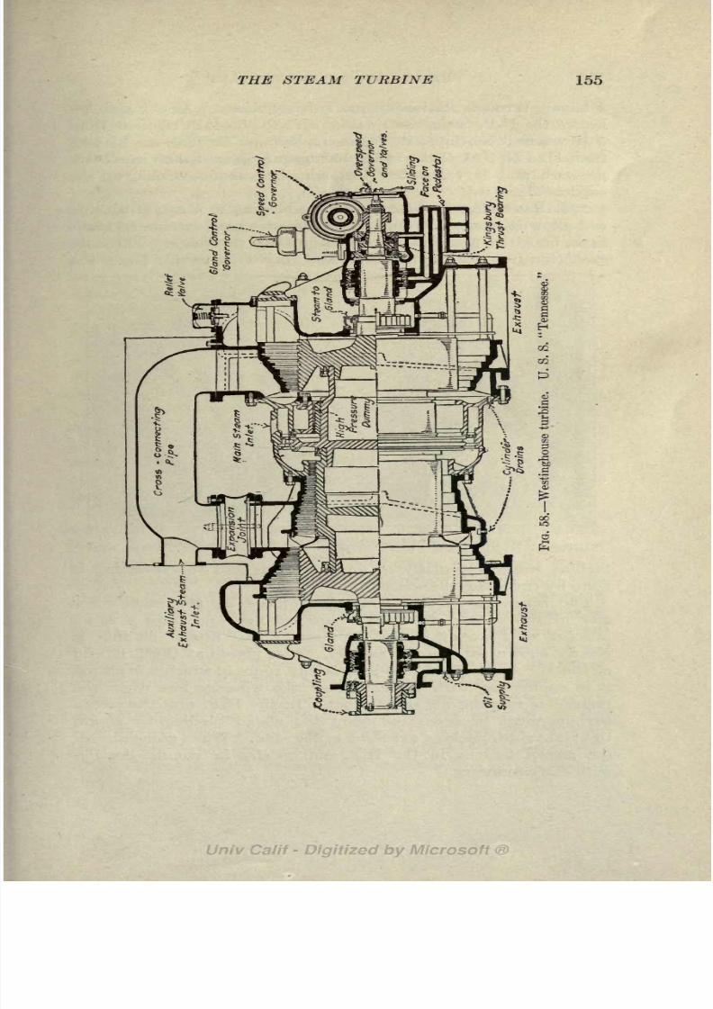
8/3/2019 Marine Power Plant Chaprich
http://slidepdf.com/reader/full/marine-power-plant-chaprich 167/335
THE STEAM TURBINE 155

8/3/2019 Marine Power Plant Chaprich
http://slidepdf.com/reader/full/marine-power-plant-chaprich 168/335
156 THE MARINE POWER PLANT
cessively through stationary and moving blades. At C the steam
leaves the H.P. casing and passes over to the L.P. element (Fig.
56b) where it continues its expansion through the Parsons bladingfrom F to H . At H the steam has been reduced to the condenser
pressure and is exhausted through the exhaust trunk to the
condenser.
107. Reversing Turbines. As the blading in a steam turbine
will allow it to operate only in one direction, all marine turbines
must be fitted with a separate turbine for reversing. The only
exception to this is when electric drive is used. Here the
FIG. 59. Construction and assembly of reaction blading.
turbine runs continually in one direction and the reversing is
done by reversing the motor.
The reversing turbine is always placed on the same rotor
and in the casing with the ahead turbine and only a small
number of rows of blades are used. The astern blading is
clearlyshown in
Figs.56 and 60. It is
placedat the L.P. end
of the L.P. unit (Fig. 56b) and as the space in which it is placed
is in connection with the condenser the windage loss when the
turbine is running ahead is small. In the H.P. unit the astern
turbine must be separated from the ahead blading by steam
tight labyrinth packing as shown in Fig. 56a. When going ahead,
the astern turbine in the H.P. unit is also in communication
with the condenser.

8/3/2019 Marine Power Plant Chaprich
http://slidepdf.com/reader/full/marine-power-plant-chaprich 169/335
THE STEAM TURBINE 157
For a geared turbine installation where the cross-compounded
turbine is
used,both units must be fitted with astern elements.
The astern turbine in such a case is also cross compounded,
the steam first passing through the H.P. blading and then through
the L.P. blading in the other unit.
The astern turbine is very inefficient due to the small amount
of blading used. Due to the low efficienny of the astern blading
the steam consumption when reversing is very high and the
astern power is only about 50 to 60 per cent of the ahead
power. This is sufficient, however, for maneuvering. Thereis a small loss when going ahead due to the friction or
windage loss in the astern blading.
108. Superheat with Turbines. With steam turbines the
flow of steam is always in one direction; hence there is no loss
due to condensation caused by hot steam coming in contact
with relative cold surfaces as is the case in reciprocating engines.
Superheat does not have the same use as with reciprocating
engines, but it is of value in increasing the initial heat contentsand decreasing the loss due to the friction and windage of the
steam in the high pressure end of the turbine. The lubricating
oil problem mentioned in discussing the use of superheat with
reciprocating engines is not present with turbines. There are
objections, however, to the use of superheat with turbines
that should be given careful attention.
The chief difficulty with superheat in marine turbines is the
variation in temperature that comes on the reversing blading.
When running ahead, the astern blading is operating in a vacuum
at a low temperature, and when full steam pressure is turned
into the astern turbine a large temperature change will take
place in the blading which will be increased when superheated
steam is used. Until recently 100 of superheat was thought to
be the highest value that it was safe to carry, but the latest
Cunard geared turbine ships are using. 200 superheat with no
apparent difficulty. When electric propulsion is used the above
objection does not hold as no astern turbine is necessary.
In fixing on the steam pressure and degree of superheat to
use with a turbine, full consideration should be given to the
question of "heat availability" discussed in Art. 89. A high
steam pressure is more desirable than a high degree of superheat.
109. Effect of High Vacuum. A consideration of the expres-

8/3/2019 Marine Power Plant Chaprich
http://slidepdf.com/reader/full/marine-power-plant-chaprich 170/335
158 THE MARINE POWER PLANT
sions for the Rankine and thermal efficiency of a turbine shows
that for high economy a high vacuum is desirable. This not
only decreases the steam consumption by decreasing H2 butalso increases the horsepower of the turbine, as each pound of
steam does a larger amount of work. In Art. 90 we saw that
27/4 in. was the highest vacuum advisable to carry with a
reciprocating engine due to the large volumes of steam to be
handled. With turbines, however, the large volume occupied bysteam at high vacua is not a detriment and only calls for longer
blade lengths at the low pressure end. The economy of a
turbine increases as the vacuum is increased up to the highest
vacuum that it is possible to maintain. Vacua higher than
29 in. are possible, but, as pointed out in Art. 90, if the vacuum
is carried too high the cost of producing it will be more than the
gain in economy attained. The tendency with marine instal-
lations, however, is not to carry as high a vacuum as is advisable
with turbines.
The foregoing chapter gives the underlying elementary thermodynamicsof the steam turbine and a description of the various types used in marine
practice. For the thermodynamics of the compound turbines, losses in
turbines, empirical methods of design, and more detailed information the
reader should consult books devoted to the steam turbine and steam turbine
design.
Details of construction and methods of operation are beyond the scope
of this book; these should be acquired by actual experience and observation
in the ship's engine room.

8/3/2019 Marine Power Plant Chaprich
http://slidepdf.com/reader/full/marine-power-plant-chaprich 171/335
CHAPTER XI
THE GEARED TURBINE AND COMBINATIONMACHINERY
110. General. As pointed out in the last chapter, mechanical
gearing has been interposed between the turbine and the propeller
in order to improve the efficiency of both propeller and turbine
by allowing each to run at the r.p.m. for best efficiency. The
introduction of the geared turbine is very recent and its develop-
ment has been extremely rapid. The first installations of the
geared turbine were in 1910 on the U.S.S."Neptune
"(West-
inghouse gears) and the S.S. "Vespasian" (Parsons gears). In
1922 more than a thousand merchant vessels 'and a like number
of naval craft have been fitted with this type of propelling
machinery.
The development of the geared turbine has been so rapid
that many failures have resulted due to lack of experience,
poor judgment in design, inferior workmanship, and mishandling
on the part of the crews. During the World War (1914-1918)
the demand for geared turbine sets was so pressing that manyfirms started building these units without proper experience of
the service conditions under which they would be used. As
the speed of production was very rapid a large number of sets
were installed before the sea trials of the first set had taken
place. The result of this has been that many shipowners
hesitate to adopt this type of machinery and the geared turbine
has continued to suffer from these early and natural mistakes.
At the present writing (1922) the geared turbine is an un-
qualified success. Experience with the unit in service at sea
both by designers and operating engineers has remedied all the
earlier mistakes and the unit is being installed without hesitation
by many engineers and shipowners. A number of ships with
geared turbines are now in operation after completing from
120,000 to 200,000 miles without gear troubles.
111. Types of Gearing. Reduction gears are built in both
159

8/3/2019 Marine Power Plant Chaprich
http://slidepdf.com/reader/full/marine-power-plant-chaprich 172/335
160 THE MARINE POWER PLANT

8/3/2019 Marine Power Plant Chaprich
http://slidepdf.com/reader/full/marine-power-plant-chaprich 173/335
THE GEARED TURBINE 161
single and double reduction units, depending upon the propeller
speed desired. Single reduction units, consisting of one set of
gears, reduce the revolutions from 1:15 to 1:20, and double
reduction units, consisting of a second pinion and gear, reduce
the r.p.m. about 1:36.
Most naval vessels, where high propellerspeeds are permissible,
use single reduction gearing. Figure 62 shows a single reduction
unit with cross-compound turbines. A number of passenger
FIG. 62. Single-reduction gears for destroyers.
vessels, cross channel steamers, and a few cargo ships have also
been fitted with single reduction sets. For these ships the
propeller speed is in the neighborhood of 125 r.p.m. and the
reduction ratio is about 1:18. This small reduction, however,
does not give the most advantageous turbine speed except for
powers between 10,000 and 20,000 s.h.p. In order to get the
lowest steam consumption possible, slow speed cargo ships of
low power should always use high turbine speed and double
reduction gearing.
The present turbine speed of 3,600 r.p.m., used with double
reduction gears, is still too low for best economy with turbines
of between 2,500 and 3,500 s.h.p. The present turbine speed
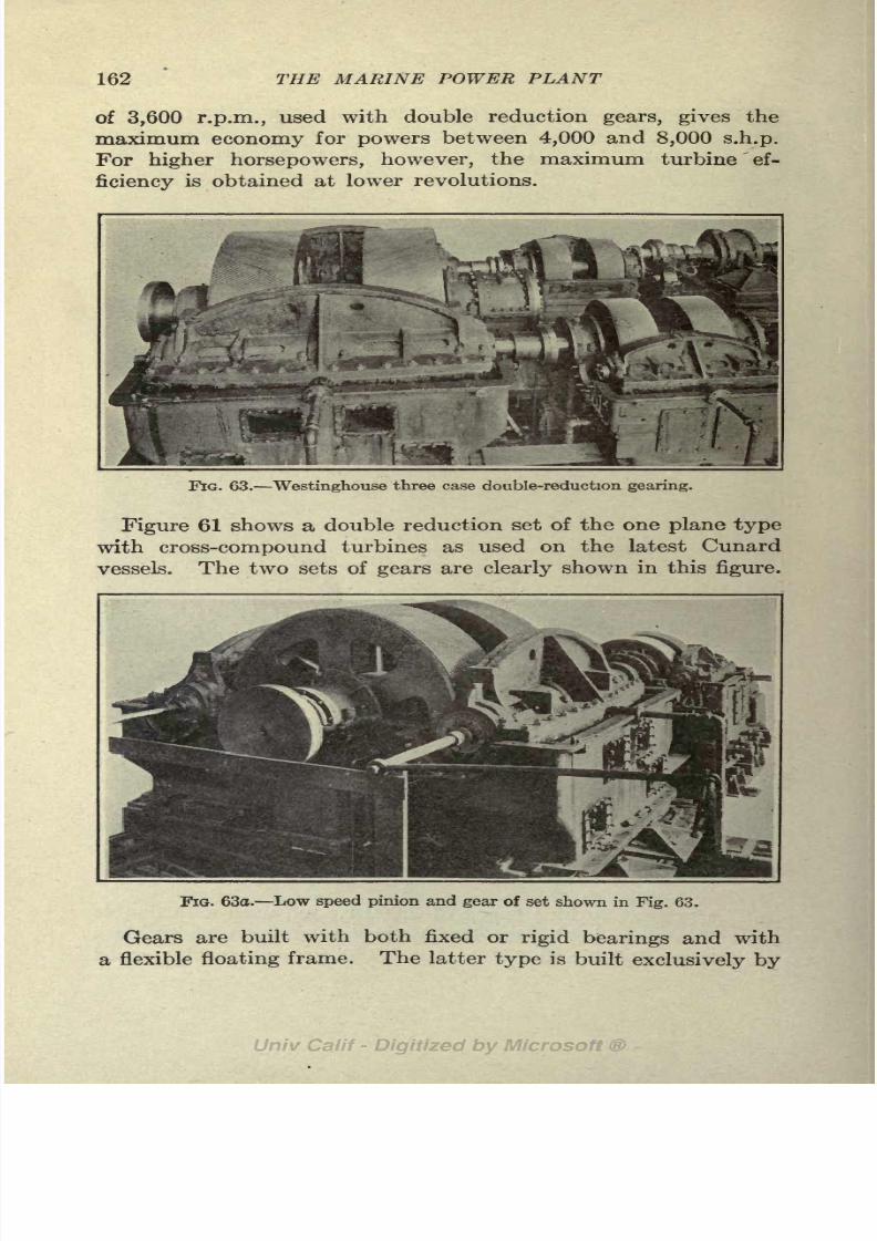
8/3/2019 Marine Power Plant Chaprich
http://slidepdf.com/reader/full/marine-power-plant-chaprich 174/335
162 THE MARINE POWER PLANT
of 3,600 r.p.m., used with double reduction gears, gives the
maximum economy for powers between 4,000 and 8,000 s.h.p.
For higher horsepowers, however, the maximum turbine ef-
ficiency is obtained at lower revolutions.
FIG. 63. Westinghouse three case double-reduction gearing.
Figure 61 shows a double reduction set of the one plane type
with cross-compound turbines as used on the latest Cunard
vessels. The two sets of gears are clearly shown in this figure.
FIG. 63o. Low speed pinion and gear of set shown in Fig. 63.
Gears are built with both fixed or rigid bearings and with
a flexible floating frame. The latter type is built exclusively by

8/3/2019 Marine Power Plant Chaprich
http://slidepdf.com/reader/full/marine-power-plant-chaprich 175/335
THE GEARED TURBINE 163
the Westinghouse Elec. & Mfg. Co. under the Melville-Macalpine
patents.All
other gear builders use the rigid bearing type.Figures 63 and 63a show views of a Westinghouse reduction gear
built for S. S. "Manalani" and "Manukai" of the Matson
Navigation Co. These gears are for a cross-compound installa-
tion of 5,500 s.h.p. The high speed pinion (enclosed in the
floating frame) and the high speed gears are shown at the right
in Fig. 63, and the low speed pinion and gear at the left. This
gear is of the three case type. The floating frame (Fig. 64) ,which
carries the driving pinion and its bearings, is independent of thehousing except for one support at the center. This arrangement
automatically maintains the alignment of the pinions and gives
FIG. 64. High speod pinion and floating frame.
a uniform distribution of tooth pressure over the tooth face.
Both the fixed bearing and floating frame types of reduction
gearing are giving excellent results in service on shipboard.
Data on a few typical installations are given in Table X.
The turbines described in Art. 106 and illustrated in Figs. 54,
55, 56a, 56b, 57 and 60 are used with the gear drive.
Figure 60 shows the General Electric Company's type of geared
turbine. This turbine consists of a single unit in contrast to the
cross-compound turbines illustrated in the other figures. The
astern blading is shown at the left hand end of the turbine.
A recent novel installation of a Parsons geared turbine on the
S. S. "Corrientes" 1consists of three units; the H.P. and I.P.
*See Engineering (London), vol. 110, p. 211.
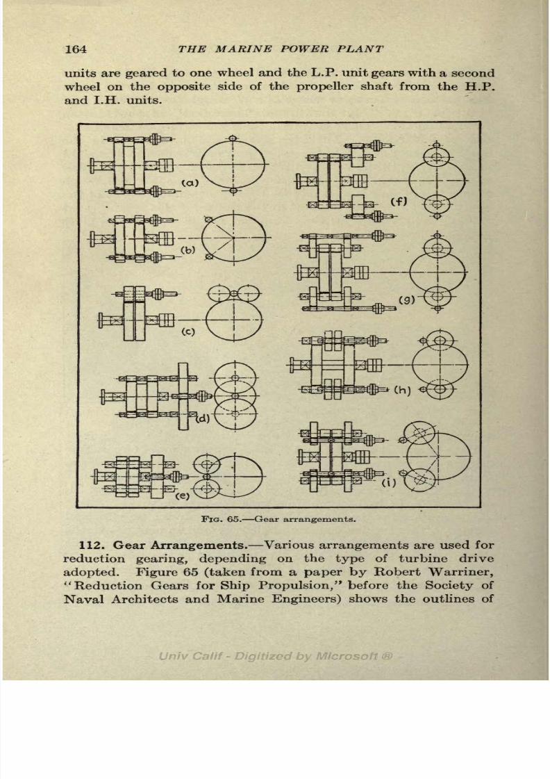
8/3/2019 Marine Power Plant Chaprich
http://slidepdf.com/reader/full/marine-power-plant-chaprich 176/335
164 THE MARINE POWER PLANT
units are geared to one wheel and the L.P. unit gears with a second
wheel on the opposite side of the propeller shaft from the H.P.
and I.H. units.
FIG. 65. Gear arrangements.
112. Gear Arrangements. Various arrangements are used for
reduction gearing, depending on the type of turbine drive
adopted. Figure 65 (taken from a paper by Robert Warriner,"Reduction Gears for Ship Propulsion/' before the Society of
Naval Architects and Marine Engineers) shows the outlines of

8/3/2019 Marine Power Plant Chaprich
http://slidepdf.com/reader/full/marine-power-plant-chaprich 177/335
THE GEARED TURBINE 165
a number of gear arrangements for both single and double
reduction.Arrangements c, d,
and e areadopted
whenonly
one turbine unit is used and the other arrangements are of the
two pinion type used with cross-compounded turbines. The
double reduction arrangements shown in g, h and i require only
one gear casing for the gearing while arrangement f requires
three gear casings. This latter arrangement is used on tankers
where the machinery is located aft. The turbines are well
separated so that the propeller shaft can be readily withdrawn
without disturbing the turbines. Thethree
case arrangementis also used for large units as shown in Fig. 63a.
113. Gear Construction. Because of the high pitch line
velocity all reduction gears are of the double herringbone or
helical type (Fig. 62), the teeth being cut right-handed on one
gear and left-handed on the other to balance the end thrust.
The involute tooth is used and the angle is generally between
22 and 45. Tooth pressures are much less than formerly used
and run between 300 and 450 Ibs. per inch of face for the high
speed elements and between 600 and 800 Ibs. for the low speed
elements. The gear wheel consists of a cast iron spider or built-
up forging with a forged steel rim shrunk on to form the face
for cutting the teeth.
Double reduction gears are built in the one plane and two
plane types. In the one plane type the center line of the
turbine and propeller shafts are in the same horizontal plane as
shown in Figs. 65a, d, f and g; in the two plane type the turbine
shafts are in a plane above that of the propeller shaft as shown
in Figs. 65b, c and h.
In the two plane type the low speed pinions are in contact
with the low speed gear near its top (Fig. 65e). This allows
an increase in the diameter of the low speed gear without neces-
sitating an increase in the diameter of the high speed gear and
a consequent increase in the distance between gear centers.
A large diameter of the low speed gear is advisable in order to
keep the tooth pressures down without unduly increasing the
width of the gear face. (See Fig. 60.)
114. Requirements for Successful Operation. In order to
avoid failure with geared turbine the utmost care must be given
to material, design, construction, installation and operation.
As already pointed out, the design of the gearing has now been

8/3/2019 Marine Power Plant Chaprich
http://slidepdf.com/reader/full/marine-power-plant-chaprich 178/335
166 THE MARINE POWER PLANT
perfected and, with the low tooth pressures used, failures due to
faulty design are now practically eliminated. Gears that have
successfully passed the shop tests have sometimes failed, how-ever, when placed in service on shipboard. The reasons for
the more severe conditions in service as compared to shop test
have now been pretty well investigated and the results of these
investigations are worthy of attention.
Tests on the S.S. "Jebsen" 1 showed that the torque varied
for a 2,000 s.h.p. unit from zero to 3,500 s.h.p. (75 per cent
overload) in 3 seconds and variations of less magnitude occurred
very rapidly over wide ranges under certain conditions. A paper
by R. J. Walker before the Inst. of Naval Architects in 1921 deals
at length with the variation in torque in geared turbine installa-
tions. An examination of the gears of the "San Florentine"
and "San Fernando/' in which the turbines were placed aft,
showed indications of excessive pressure at definite angular
positions around the gear. This was shown conclusively to be
caused by variations in the resistance of the propeller blade due
to the variations in intensity of the wake. The wake intensity
varied over the propeller disc area, being a maximum at the
center line of the stern post and close to the surface. In these
ships, the frequency of the four blades of the propeller passing
the stern post also synchronized with the natural period of
torsional vibrations of the shaft. The synchronism was de-
stroyed by fitting a three-bladed propeller. A careful study of
the variation in the torque by means of the torsion meter showedvariations of 30 per cent each side of the mean value, a maximum
and minimum occurring four times a revolution. For a pro-
peller running at 90 r.p.m. this would give variations in torque
of about 60 per cent twelve times a second.
From the foregoing it is seen that care must be exercised
that the natural period of torsional vibration of the shaft, fixed
by the amount of inertia of the propeller and gearing and
flexibility of the shaft, does not synchronize with the variation
in propeller wake.
The variation in the propeller load occurs as the blades pass
through the strong wake current at the stern post; hence the
frequency becomes four times the r.p.m. for a four-bladed
propeller and three times the r.p.m. for a three-bladed propeller.
1 General Electric Review, Feb., 1921.

8/3/2019 Marine Power Plant Chaprich
http://slidepdf.com/reader/full/marine-power-plant-chaprich 179/335
THE GEARED TURBINE 167
Gears fitted aft have been found to wear more quickly than
those placed amidships due to the shorter length of shaft between
gears and propeller. The long flexible line shafting used when
the turbine is installed amidship dampens out some of the
variation in torque caused by the irregular action of the propeller.
The successful operation of gears calls for exact attention to
lubrication. Not only must a regular and adequate supply of
lubricating oil be supplied to the gears and bearings but the
oil supply must be kept free from grit, lint, foreign matter and
all traces of salt water.
115. Lubricating Oil System. Three types of lubricating oil
systems are used for lubricating the gears and turbine bearings:
the pressure system, the gravity system, and the combined
pressure-gravity system. In the pressure system the oil is
supplied direct to the gears and bearings by the lubricating
oil pump. In the gravity system the pump delivers the oil to
overhead tanks and the oil flows from the tanks to the gearing
by gravity.In the
pressure-gravity systemoil is
supplied bythe oil pump direct to the bearings and gears as in the pressure
system. The pumps operate, however, at a higher rate than
necessary and the excess oil passes through a relief valve to an
overhead gravity tank. If for any reason the pressure falls,
the supply in the gravity tank automatically flows to the gears
and bearings, thus insuring a temporary supply until the pumpcan be started or the turbine stopped. The former system is
used almost universally on navalvessels
as thereis
notsuf-
ficient height to install a gravity system. The gravity system
is by far the best system and is used with practically all geared
turbine installations on merchant ships.
A gravity lubricating oiling system used by the De Laval
Steam Turbine Co. is shown in Fig. 66, and one used with West-
inghouse gears in Fig. 67. This is typical of all gravity systems.
The advantage of the gravity system is that in case of any
accident to the pump the oil supply in the gravity tanks is
sufficient to last several minutes, giving the engineer on watch
time to shut down the turbine before the oil supply, fails.
As shown in Fig. 66 the oil from the gear casing and turbine
bearings drains to a sump tank below the engine room flooring.
From here it is pumped by the lubricating oil pump to the
overhead gravity tanks. An oil cooler is interposed in the

8/3/2019 Marine Power Plant Chaprich
http://slidepdf.com/reader/full/marine-power-plant-chaprich 180/335
168 THE MARINE POWER PLANT

8/3/2019 Marine Power Plant Chaprich
http://slidepdf.com/reader/full/marine-power-plant-chaprich 181/335
THE GEARED TURBINE 169
f .' This Pipe is to be swung out of the waywhen not in use.
Connect to Steam
Funnel for' ~ '
filling SystemManhole, ,vent
2 Perforated'
A suitable platform .
anddrain pan shouldbe
proyided here for cleaning
Dram fro*Drainers.
Strainer'; OilLevel.' i
Gage61ass \
Gravitv Tanktjraviry
ianx
'Drain from abouf00 Gal.
,- Sett/ing Tank Gravity Capacity
Sream Heating Coil for
maintaining a Temperatureof about ISO" F
- Drain from Reserve Tank
Centrifugal Oil Purifier
or Pressure Filter
Main Oil ....
Supply Pipe
Thermometer
Spring LoadedReliefValve may be maintaine
in open position.
-Dram from Propelling Unit
nk about60O Go/. Capacity
BY PERMISSION MARINE ENGINEERING
FIG. 67. Lubricating oil system for \Vestinghouse geared turbine.

8/3/2019 Marine Power Plant Chaprich
http://slidepdf.com/reader/full/marine-power-plant-chaprich 182/335
170 THE MARINE POWER PLANT
discharge of the pump to remove the heat absorbed by the
oil in its passage through the gears and bearings. The oil
supplyto the turbine is withdrawn from the
gravitytanks at a
point somewhat above the bottom. This allows all water and
sediment to settle to the bottom of the tank where it can be
drawn off to the oil separator. The arrangement is clearly
shown in Fig. 66. Centrifugal purifiers are installed in all
lubricating oil systems for removing water and foreign matter
from the oil. If used while underway a large part of the foreign
matter will settle out. In port the whole oil supply can be
put through the purifier in a short time.
When the pressure system is used, the throttle valve to the
turbine should be designed to be held open by the oil pressure.
With this device a failure of the oil pump or oil supply would
immediately cause the throttle to close before any serious damagecould result. Electric alarms should be fitted on all systems to
notify the engineer of any falling off in the oil supply.
116. Essential Requirements of an Oiling System. The oiling
system is by far the most important auxiliary installed in a
geared turbine ship and it is essential that in design and opera-
tion it be the best possible to obtain. The requirements for
an oiling system may be summed up as follows:
1. Oil temperature. The same supply of lubricating oil is
used for both gears and bearings. The duty of the oil is to
carry awaythe heat
generated byfriction as well as to lubricate
;
hence the oil leaves at a temperature higher than that at which
it entered. Gears operate best with the oil, entering at a low
temperature, while bearings wear longer with an oil of higher
temperature and lower viscosity. If oil of high viscosity were
used for the gears the spray nozzles would not function and the
pumping of the oil would involve difficulties; hence the viscosity
of the oil must be kept low. The temperature used for the oil
entering the bearings and gears is between 90 and 120F.The oil should have a Saybolt viscosity between 300 and 500
seconds at 100F. The oil supply should be sufficient to carry
away the heat generated (about 5 per cent of the shaft horse
power) with a rise in temperature of 10 or 20F. Oil coolers are
fitted for reducing the temperature back to the proper value
for entering the gears and bearings, i.e., between 100 and

8/3/2019 Marine Power Plant Chaprich
http://slidepdf.com/reader/full/marine-power-plant-chaprich 183/335
THE GEARED TURBINE 171
110F. When operating in cold water the cooler may often be
by-passed. It is advisable to fit coolers in duplicate.2. Oil pressure. The gravity tanks should be high enough to
give a pressure at the gear nozzles and bearings of between 6
and 7 Ibs. per square inch. To obtain this pressure and to
give sufficient head to overcome the losses in valves, strainers
and pipes, the overflow of the gravity tank should be located
between 25 and 30 feet above the center line of the shaft.
3. Oil supply. The practice with geared turbines is to make
the capacity of the gravity tanks sufficient to hold about fouror five minutes
'
supply . With powers between 2,500 and 3,500
s.h.p. and 10 rise in temperature this will require two 500 or
600 gallon tanks. A third tank (see Fig. 66) of about the same
capacity is fitted as a reserve tank. The sump or drain tank
below the turbine is given a capacity of between 500 and 1,000
gallons for horsepowers mentioned above. For a reasonably
tight system, leakage should not exceed a gallon per day.
4- Cleanliness of Oil. It is very essential that the oil supply
be kept absolutely clean; and dirt, sediment, water and lint
be kept out of the system. Filters and strainers should be
installed in the system, as well as a centrifugal purifier (Figs.
66 and 67) to purify the oil that settles in the bottom of the
gravity tanks. As water, and especially salt water, is disastrous,
it is advisable to have the oil pressure in the coolers greater than
that of the salt circulating water, for then any leakage that
occurs will be a leakage of oil overboard instead of salt water
into the system.
117. Combination Machinery. This type of machinery con-
sists of a triple screw arrangement with two triple expansion
engines on the wing shafts exhausting to a low-pressure turbine
on the center shaft. It is an excellent arrangement on account
of the high efficiency of the reciprocating engines at high pres-
sures and the high efficiency of the turbine at low pressures.
The low pressure end of the triple expansion engine is very
inefficient due to the large volume of steam handled, high
cylinder condensation, friction and leakage. The high pressure
end, however, is very efficient if a small degree of superheat is
used to eliminate the cylinder condensation up to cut-off. The
high pressure end of the turbine, on the other hand, is not
so efficient as the low pressure end, due to the greater friction

8/3/2019 Marine Power Plant Chaprich
http://slidepdf.com/reader/full/marine-power-plant-chaprich 184/335
172 THE MARINE POWER PLANT
of high pressure steam. As pointed out in Art. 109, the L.P.
turbine can use a high vacuum to good advantage, increasing
the horsepower and economy thereby.
The disadvantages of the installation are its bulkiness and
large fore and aft space required to install the center line L.P.
turbine aft of the reciprocating wing engines. If the three
units can be installed abreast this disadvantage does not exist.
Unless a high vacuum is carried and theL.P.turbinebladed for
the highest possible vacuum, the gain in economy will not be
realized. The weight and space occupied is greater than that
of the geared turbine.
Combination machinery makes an ideal installation for low
r.p.m. and the economy is as good as that of the high speed
turbine and will give a substantial increase in power over that
possible with triple expansion engines alone. Except for the
introduction of the geared turbine this type of machinery would
have been used to a larger extent.
Combinationmachinery
has been fitted on the"Otaki,"
"Rochambeau," "Olympic," and "Minnekahda."
118. The Combination Machinery Installation on S.S. "Otaki."
This was the first installation of this type of machinery and
as sister ships, the S.S. "Onari" and S.S. "Oparva," were fitted
with twin reciprocating engines, comparisons in service are
available. The"Otaki" was lengthened 4 ft. 6 in. over her
sister ships to make up for the cargo space lost by the third shaft
alley. Otherwise the hulls were identical. It developed on the
trials that the reduction in fuel consumption and reduced size of
boilers required on the"Otaki" were more than enough to com-
pensate for the space lost by the shaft alley.
The principal characteristics of the "Otaki" are:
L.B.P. = 464 Displacement = 11,700 tons
D.w. =9,000 tons Draft =27 ft. 6 in.
Speed=12 knots fully loaded; 14 knots with 5,000 tons d.w.
In going astern only the reciprocating engines are used; hence
the turbine is not equipped with astern blading. Two con-
densers are fitted so that when reversing each reciprocating
engine can exhaust to a separate condenser. The ratio of the
H.P. and L.P. cylinders is 1:5.6 and on the sister ships the ratio
is 1:7.93. The boiler pressure used was 196 Ibs. abs. and the

8/3/2019 Marine Power Plant Chaprich
http://slidepdf.com/reader/full/marine-power-plant-chaprich 185/335
THE GEARED TURBINE 173
vacuum was 28.2 in. The L.P. cylinder exhaust was 11.5
Ibs. absolute and the initial pressure at the entrance of theturbine was 9.8 Ibs. abs. One-third of the total power was
developed in each unit. The steam consumption on the"Otaki
"
was 13.7 Ibs. per I.H.P. per hour against 16.5 Ibs. on the "Onari."
The machinery weight of the "Otaki" is only 3.25 per cent
greater than that of the sister ships.
The real comparison, of course, is in the results obtained in
service, where it was found that the fuel consumption of the
"Otaki" with combination machinery averaged between 12 and15 per cent less than used on the sister ships with twin triple
expansion engines.
TABLE X. TYPICAL REDUCTION GEARS
Ship

8/3/2019 Marine Power Plant Chaprich
http://slidepdf.com/reader/full/marine-power-plant-chaprich 186/335
CHAPTER XII
THE ELECTRIC DRIVE
The electric drive is a recognized form of ship propulsion and
hasproven
itself
beyondall doubt as a reliable
and economicaltype. Several battleships and a number of cargo vessels and
smaller craft have been fitted with electric drive and have been
highly successful in service.
119. Advantages. The outstanding advantages of this type
of propulsion are: flexibility of control, large reversing torque,
and, in some installations, high economy at reduced speeds.
Due to these features, it is the ideal machinery for battleships
and other types of ships where ease of maneuvering and high
economy at low speeds are essential. Its suitability for
merchant ships is a much debated question today. In space
occupied, weight, cost, and economy at full power, the electric
drive has no advantages over the geared turbine. Because of
its excessive weight and large space required, electric propulsion
is not applicable to high speed ships. A full comparison of
this type of propulsion with the other standard types is given
in Chap. XIV.
While the design and selection of the types of motors and
generators and the installation of the electrical machinery and
its controls belong in the field of the electrical engineer, it is
highly essential that the marine engineer and naval architect be
thoroughly conversant with this important type of propelling
machinery.
120. Essential Features. The electric drive is essentially aform of reduction gear. The current is generated by a two-
pole, high speed turbine driven generator and is transmitted to
a low speed, multi-pole motor on the propeller shaft. The
steam turbine that drives the generator runs at speeds between
2,000 and 3,500 r.p.m., which is practically the same speed as
used with geared turbine installations. This gives a small,
174

8/3/2019 Marine Power Plant Chaprich
http://slidepdf.com/reader/full/marine-power-plant-chaprich 187/335
THE ELECTRIC DRIVE 175
light weight turbine of high efficiency that is ideal for use on
shipboard.
In order to allow the use of a light, high speed generator,
alternating current of high voltage has been used in all in-
stallations of any appreciable power. After further develop-
ments of high speed direct current generators of high voltage,
this type of machinery may be introduced.
The revolutions of the propeller, and hence the speed of the
ship, are controlled as follows:
1 . By varying the speed of the turbine and thus changing the
frequency of the current.
2. By special motor windings whereby the number of poles may be
varied.
3. By shutting down one of the generators when more than one is
installed.
4. By inserting resistance in the rotor circuit, when the induction
motor is used.
121. Types of Propelling Motors. Several different types of
motors have been advocated for ship propulsion and practically
all of these have been installed and are now in service. Each
type of motor has its own advocates and each has some merits
and advantages not possessed by the others.
The types of motors used for ships populsion are:
1. Ordinary wound secondary induction motor.
2. Squirrel cage motor.
3. Combined squirrel cage and wound secondary.
4. Synchronous motor.
Diagrammatic schemes of all the above types are shown in
Figs. 68, 69, 70 and 71.l
The induction motor with secondary control inserted in the
rotor circuit has been used on some electrically propelled ships.
This gives a motor with good torque characteristics for reversing
and is used where a large amount of quick reversing is necessary.
On cargo ships the inserted resistance is used to give a high
torque in starting and reversing and is short circuited at full
speed; on the U. S. S. "Tennessee" the secondary windings have
lfrhese figures have been taken from a paper by W. E. Thau before the
Society of Naval Architects and Marine Engineers, 1921. This paper
gives an excellent discussion of electric propulsion and has been drawn from
in preparing this chapter.

8/3/2019 Marine Power Plant Chaprich
http://slidepdf.com/reader/full/marine-power-plant-chaprich 188/335
176 THE MARINE POWER PLANT
a variable control and are used with liquid rheostats for con-
trolling the speed of the motor.
The synchronous motor appears to be in favor for merchant
ship drives. Where only a small amount of maneuvering is
necessary this is probably an ideal motor. For maneuvering,
FIG. 68. Diagram of synchronous motor installation.
the motor is operated as an induction motor and is built with a
substantial squirrel cage winding. The synchronous motor is
more efficient than the induction motor and has a unity powerfactor against a power factor of .70 to .80 for the induction
motor. The synchronous motor is 'appreciably lighter and
Exciter Set
11

8/3/2019 Marine Power Plant Chaprich
http://slidepdf.com/reader/full/marine-power-plant-chaprich 189/335
THE ELECTRIC DRIVE 177
excited by an independently driven D. C. generator. (See
Fig. 68.)The induction motor with power factor correction has been
also proposed. It has the additional complication of the phase
advancer but is claimed to be lighter and less expensive than the
Exciter Set
I
Reversers
J2S1headj
Secondary
Control
WoundSecon-
daryInductionMotor
Fio. 70. Diagram of induction motor installation.
ordinary induction motor and to offer all the advantages of
both the induction and synchronous motors.
The motors for ship use are built smaller than those used on
shore and consequently are provided with independently driven
fans for cooling. (See Fig. 106.)
Exciter Set
FIG. 71. Diagram of installation with phase advancer.
122. Generators. A high speed, three phase, two pole A. C.
generator is used for supplying the current for the motors. The
speed of the generator is fixed by the required r.p.m. of the pro-
peller and the number of poles used in the motor. The larger

8/3/2019 Marine Power Plant Chaprich
http://slidepdf.com/reader/full/marine-power-plant-chaprich 190/335
178 THE MARINE POWER PLANT.
the number of motor poles used, the greater will be the speed
reduction. Motors for cargo ships have been built with 60
poles and running at 100 r.p.m.; this allows 3,000 r.p.m. for atwo pole generator. The upper limit of the number of poles in
the motor is probably in the neighborhood of 72, which will
allow a maximum generator speed of 3,240 r.p.m. with 90 r.p.m.
at the propeller.
All merchant ships so far fitted with electric propulsion have
used only one generator and one motor while the battleships
have been fitted with two generators and four motors.2
The power developed by the motor depends upon the field
excitation of the generator and the speed of the turbine. To
meet momentary variations in power during maneuvering, turn-
ing of the ship and variations in sea conditions, and to provide
a high torque for braking and quick reversing and starting, the
generator field is over excited.
On the "New Mexico" booster generators are used to add to
or subtract from the field excitation withoutchanging
the
voltageof the exciter generator.
123. Speed Control. On merchant vessels the speed of the
propeller, and hence the speed of the ship, is varied by changing
speed of the turbine. Varying the speed of the turbine driven
generator, varies the frequency of the current and hence changes
the revolutions of the motor.
When the speed of the ship is controlled by changing the speed
of the turbine, the economy falls off as the turbine r.p.m. are
reduced, and the electric drive has no better economy at low
speeds than the geared turbine.
In naval vessels two generators are used and the motors are
wound so that two combinations of poles can be used. This
allows the turbines to run at full speed for several speeds of the
propelling motor and thus high steam economy at reduced speeds
of the ship is possible.
As merchant ships run practically the entire time at full speed
the features used in naval vessels for providing economy at
reduced speeds are not required. A high speed passenger ship,
however, which has a sea speed of between 20 and 23 knots if
fitted with electric drive, should be equipped with two gener-
ators or pole changing motors so that high economy can
be had at speeds around 16 to 18 knots. This will allow such
2
See article on generators in General Electric Review, Feb., 1921.

8/3/2019 Marine Power Plant Chaprich
http://slidepdf.com/reader/full/marine-power-plant-chaprich 191/335
THE ELECTRIC DRIVE 179
a ship to run at reduced speeds with low steam consumption
when traveling conditions do not warrant full speed on the
passage. For the above conditions the electric drive offers
advantages not possessed by the geared turbine.
124. Starting and Reversing. In starting a ship fitted with
an induction motor, the turbine is first brought up to idling speed;
the reversing switch is put in the "ahead" position; and the
generator field switch is closed and excitation established.
As soon as the motor comes up to a steady speed the secondary
winding is short circuited and the motor is brought up to the
desired speed by increasing the speed of the turbine. All opera-
tions are performed by levers at one control station.
In reversing when underway at full speed, the turbine speed
is reduced to idling speed (about one-third full speed), the
field switch is opened and the reversing switch is thrown from
"ahead" to "astern" position. The generator field is then
excited and as soon as the motor speed has become steady it is
brought up to the desired speed as before in step with the turbine.
A complete system of interlocks is provided so that no operation
can be performed out of its sequence by an inexperienced engineer.
The propelling motor must not only develop a driving torque
quickly when reversed but it must also have a braking effect in
order to bring the propeller to rest before it is reversed. Motors
with special winding are necessary to give these characteristics.
125.
Special
Features of the U. S. S. "New Mexico" Instal-
lation. The electrical equipment on the "New Mexico" consists
of two turbine generator units of 10,500 kw. each, running at
2,100 r.p.m.; and four double squirrel cage, pole changing motors
running at 167 r.p.m. The motors are direct connected to the
propeller shafts. Fig. 107 shows a layout of this installation.
The generators are so wound that two voltage connections
are available a 3,000 voltage and a 4,240 voltage connection.
The motor stator
windingsare wound so that either a 24
poleor
36 pole arrangement is possible.
Between 15 and 17 knots one generator drives four motors
and the low voltage generator connection is used; above 17 knots
one generator drives two motors and the high voltage connection
is used. This arrangement, together with the pole changing
motor, gives high efficiency over a wide range of speeds. The
speed of the ship is controlled by the speed cf the turbines, the

8/3/2019 Marine Power Plant Chaprich
http://slidepdf.com/reader/full/marine-power-plant-chaprich 192/335
180 THE MARINE POWER PLANT
number of motor poles, and the number of generators in operation.
Although the double squirrel cage winding gives a larger motor,
it has the advantage of a high reversing torque and a low resist-
ance path at full speed.
For speeds up to 15 knots one generator is used with the low
voltage winding and the motors are connected up so that 36
poles are used. The propeller speed, and hence the speed of
the ship, is changed by varying the turbine speed. From 15 to
17 knots one generator is used with the low voltage windings as
before, but the motors are connected up so that the 24 pole
arrangement is used. Variations in the motor r.p.m. over this
range is controlled by the speed of the turbine generator.
From 17 knots to full speed both generators are used with
the high voltage winding and the motors are connected up for
the 24 pole arrangement.
The above arrangement allows the turbines to run at full
r.p.m. and maximum efficiency for a number of different speeds
of the ship. The variation in the turbine speed is small for
large changes in the ship's speed, resulting in a rather flat curve
for steam consumption per S.H.P. when plotted against the
speed of the ship.
126. Diesel-Electric Drive. The Diesel-electric drive is in
principle similar to the turbine-electric drive. Generators driven
by medium speed Diesel engines furnish the power for the low
speed motor on the propeller shaft. The advantages claimed
for this type of propulsion are the same as those of the turbine-
electric drive, namely, flexibility of control, economy at low
speeds and ease of reversing.
For large merchant ships, the Diesel-electric drive is between
15 and 25 per cent lighter, and probably somewhat cheaper
than direct Diesel propulsion, due to the higher speeds used
with the Diesel engines. The spaces occupied by the two
typesare
practically
the same. The Diesel-electric system,
however, is more complicated because of the larger number
of Diesel units used and the added electrical equipment. The
fuel per S.H.P. to the propeller is about 25 per cent greater due
to the electrical transmission losses and the higher fuel consump-
tion of the high speed Diesel engines. No better propeller
efficiency can be claimed for the single screw drive at 90 r.p.m.
than for the twin screw drive at 115 to 120 r.p.m.

8/3/2019 Marine Power Plant Chaprich
http://slidepdf.com/reader/full/marine-power-plant-chaprich 193/335
THE ELECTRIC DRIVE 181
Several small installations of Diesel-electric drive are in oper-
ation and some larger ones are now building. Notable amongthe existing installations are the "Tynemouth,
"a small cargo
ship of 500 s.h.p.; the "Mariner," a trawler of 400 s.h.p.; and the
"Guinevere," a schooner yacht of 550 s.h.p. The Western
Union cable ship now under construction will have an installa-
tion of 2,000 s.h.p.
127. Description of the Diesel-Electric Drive. An installa-
tion of this type of machinery on a single screw cargo ship will
consist of 4 to8 Diesel engine generator units running at between
200 and 300 r.p.m. and one double-armature motor running at
90 or 100 r.p.m.
Diesel engines of small powers and 200 to 250 r.p.m. can now
be obtained from a number of builders and because of the higher
r.p.m., and in some cases standardization, sell at a lower cost
per horsepower than engines of large power.
Because of the large number of generators used and the diffi-
culty of close regulation with Diesel engines, direct current has
been adopted in place of the alternating current used with turbo-
electric drive. The generators are operated in series, with
generator voltage control which gives a simple and.very efficient
arrangement.
The installation on the Western Union cable ship consists of
four 410-kw. 250-volt Diesel generating sets running at 250 r.p.m.
and two 1,000 s.h.p. motors turning 120 r.p.m. Two generators
connected in series supply current at 500 volts to one motor.
When a single screw arrangement is used a double-armature
motor is adopted with 500 to 750 volts on each armature.
The speed of the motor is controlled by varying the excitation
of the generator field. The motor fields are excited from a
separate source which is kept constant and in one direction at
all speeds. The speed on the motor will thus vary directly with
the generator voltage and the propeller speed can be controlled
directly from the field rheostat. Full speed ahead or astern
can be obtained at the motor without opening any circuit by
simply varying or reversing the generator field current. The
control is thus almost ideal and even better than that of the
turbo-electric drive.
Advocates of the Diesel-electric drive frequently propose the
use of Diesel engines of extremely high r.p.m. to decrease the

8/3/2019 Marine Power Plant Chaprich
http://slidepdf.com/reader/full/marine-power-plant-chaprich 194/335
182 THE MARINE POWER PLANT
size, weight, and cost of the installation. As pointed out in
Chap. XIII, Diesel engines running at speeds much over 250
r.p.m. are not feasible today for continuous commercial service.
Submarine engines have been built operating at speeds as high as
450 r.p.m., but these r.p.m. are maintained only for short runs
at full speed. The present day tendency is to reduce the full
speed r.p.m. and the latest types of submarine engines run at
350 to 375 r.p.m. at full speed.
With the Diesel-electric drive, reversing gear can be elimi-
nated on all the engines and air starting gear can be omitted from
all but one engine, the remaining sets being started by using the
generators as motors. However, a large merchant ship installa-
tion will be extremely complicated with 6-cylinder engines
and the large number of valves to keep in order. While this
type of machinery apparently offers no advantages for large
merchant ships it has many valuable features for small craft
and vessels of special types.
TABLE XI. REPRESENTATIVE ELECTRICALLY PROPELLED SHIPS

8/3/2019 Marine Power Plant Chaprich
http://slidepdf.com/reader/full/marine-power-plant-chaprich 195/335
CHAPTER XIII
THE DIESEL ENGINE
128. The Diesel Cycle. A PV diagram of the Diesel cycle is
shown in Fig. 72 and a T<f> diagram in Fig. 73. The heat is
added with an increase in temperature along the constant pres-
sure line ab; adiabatic expansion takes place along be; the heat
FIG. 72. PV diagram of Diesel
cycle.''
FIG. 73. T< diagram of Diesel
cycle.
is rejected along the constant volume line cd; and an adiabatic
compression from d to a completes the cycle.
The heat received along ab is,
The heat rejected along cd is,
The efficiency of the cycle becomes,
CP (tb -ta)
= i _ /! *-k)\
\n (tb -ta)J
where
183

8/3/2019 Marine Power Plant Chaprich
http://slidepdf.com/reader/full/marine-power-plant-chaprich 196/335
184 THE MARINE POWER PLANT
This can be reduced to,
r
Efficiency= 1 - <
-( y
"' 1
I \VJ
The expression for efficiency involves the term! rf as
in the Otto cycle, showing that the efficiency depends upon the
range of compression. It also involves the ratio of cut-off
volume to clearance volume, (T/~ ).
The efficiency of the Diesel
\ /
engine is higher than that of engines working on the Otto cycle
because of the higher compression pressure used. Theoretically
(a) First stroke (ad-
mission stroke)Piston travels
down;admission
valve open; cylin-
der is being Ailed
with pure air
(b)
(c
) Second stroke
ompressionstroke). Piston trav-
els
up:aU valves
closed; air in cyl-
inder is being com-
pressed.
(c) Third stroke
(power stroke). Pis-
ton travels down;fuel valve
openat
top dead-center,but closed at frac-
tion of stroke; gases
expand.
(d) Fourth stroke
(exhaust stroke).Piston travels up;
exhaust valve open;burnt gases are be-
ing expelled from
cylinder.
COURTESY OF BUSCH SULZER DIESEL ENGINE CO.
FIG. 74. Four-cycle Diesel engine.
the shorter the cut-off the higher the efficiency; but this does not
exist in practice.
TheDiesel
engineis
named after the inventor of the cycle,Dr. Rudolph Diesel. In working up his engine, it was the hopeof Diesel to obtain an isothermal admission instead of a constant
pressure admission, and thus approach the Carnot cycle.
129. Mechanical Operation. The Diesel engine operates on
both the two and four stroke cycle, the same as the Otto engine.
Heavy grades of oil are used for fuel and no electric sparking
device is needed as the fuel is ignited by the heat of compression.

8/3/2019 Marine Power Plant Chaprich
http://slidepdf.com/reader/full/marine-power-plant-chaprich 197/335
THE DIESEL ENGINE 185
In the four stroke cycle, or, as it is commonly called, the four
cycle engine, four strokes of the piston are required to completethe cycle. Consider view (a) in Fig. 74. As the piston moves
down, the admission valve is opened mechanically and a charge
of pure air is drawn in. At the end of the down stroke the
admission valve is closed and the piston begins its upward stroke
(6), compressing the air to about 500 Ibs. per square inch.
When the piston reaches the end of this upward stroke, the
spray valve opens for a small fraction of the stroke and finely
atomized fuel oil is sprayed into the combustion space. Dueto the heat of compression the fuel is ignited and burns during
the time that the fuel valve is open. The fuel spray valve
then closes and the gases expand, forcing the piston down on
(a) Piston traveling
down: all valves
and ports closed:
fuel injected and
burnt during first
part of stroke: gasea
expand.
(b) Piston travel-
ing down;piston
uncovers exhaust
ports; burnt gases
escape through ex-
hauat ports, reduc-
ing their pressure
to atmospheric
(c) Piston travelingdown; exlvaustports still uncov-
ered:
COURTESY OF BUSCH SULZER DIESEL ENGINE CO.
valves open . air
under light pressure
enters throughscavenging valves,
and blows gases outof cylinder.
(d) Piston traveling
up; piston covers
exhaust ports; scav-
enging valve closed :
air in cylinder is
being compressed.
FIG. 75. Two-cycle Diesel engine.
its working stroke (c). At the end of the third stroke the ex-
haust valve in the top of the cylinder opens and the piston rises
on its fourth stroke (d), forcing the burnt gases out. The ex-
haust valve then closes and the cycle is repeated. It will be
observed that four strokes are necessary to complete the cycle
and, as the engine is only single acting, there is only one work-
ing stroke during the cycle.
The two stroke cycle or two cycle engine requires but two
strokes to complete the cycle. In Fig. 75 at (a) the piston is
at the top of its stroke with pure air compressed in the clearance

8/3/2019 Marine Power Plant Chaprich
http://slidepdf.com/reader/full/marine-power-plant-chaprich 198/335
186 THE MARINE POWER PLANT
space. The fuel valve opens and a small quantity of finely
atomized oil is sprayed in. The fuel valve then closes and the
piston starts down on its working stroke, the gases expanding
behind the piston. As the piston reaches the end of its stroke
(6) it uncovers ports in the cylinder walls and the burnt gases
escape. An instant later (c) the scavenging valve in the top of
the cylinder is opened mechanically and air under low pressure
is forced in to drive out the burnt gases and fill the cylinder with
pure air. The piston then starts up on its second stroke (d)
and compresses the air. At the top of the stroke the spray
valve again opens and the cycle is repeated.
It will be observed that only two strokes are required to com-
plete the cycle and that there is a working stroke once every
revolution instead of every other revolution as is the case with
the four cycle engine.
In the two cycle engine the scavenging of the cylinder and the
filling of the cylinder volume with air take place at the end of
the down stroke by using air under low pressure, while in thefour cycle engine two idle strokes are used, one for scavenging
and one for drawing in the fresh air charge. The two cycle
engine requires a scavenging air pump to supply the scavenging
air at the end of the working stroke.
Practically all marine Diesel engines are single acting. The
notable exception is the double acting engines of the motorship"Fritz" which are three cylinder, 850 S.H.P. engines, 17 3/4 X
28 in. running at 120 r.p.m.
130. Fuel Injection Systems. There are two methods of in-
jecting the fuel oil into the cylinder of the Diesel engine air
injection and solid injection. Air injection is the most generally
used and is the one first used with Diesel engines.
The fuel system consists of fuel pumps, fuel oil piping, fuel
spray valve, high pressure air compressor, air coolers, spray air
flasks and air piping and control gear at the control station.
The fuel or spray valve is one of the most important parts of
the Diesel engine and each manufacturer has his own particular
type. The fuel valve has a dual function: (1) that of a valve
for admitting the fuel supply to the cylinder at the proper point
in the cycle; and (2) that of an atomizer for breaking the fuel
up into a fine fog like spray.
131. Air Injection System. A measured amount of fuel oil

8/3/2019 Marine Power Plant Chaprich
http://slidepdf.com/reader/full/marine-power-plant-chaprich 199/335
THE DIESEL ENGINE 187
is delivered to a pocket in the fuel valve by a plunger of the fuel
pumpwhile the fuel valve is closed. At the
proper pointin
the cycle the fuel valve is opened by the valve gear and the fuel
is forced into the combustion space by high pressure air. There
is no valve in the h.p. air line and the fuel valves are always in
communication with the spray air flasks. The object of supply-
ing air is to atomize the fuel in the passages of the fuel valve
and to insure that it enters the cylinder in a finely divided
state so that complete and rapid combustion will take place.
The amountof fuel delivered to the
sprayvalve
dependsupon the length of the working stroke of the fuel pump. One
method of controlling the fuel supply is to hold open the
suction valves of the pump during part of the pressure stroke
and thus allow part of the fuel to be returned back to the supply
tank. Both the hand and governor control are attached to the
suction valves of the pump and thus the control of the fuel
supply, and hence the speed of the engine, are regulated as
desired. Separate plungers are provided in the fuel pump foreach cylinder, or each pair of cylinders that can be grouped,
as the fuel supply must be delivered to the fuel valve while
it is closed. The fuel pump is always driven by the main engine.
The spray air is compressed in a three stage compressor to a
pressure between 800 and 1,200 Ibs. per sq. in. This compressor
is driven from the main crankshaft and is built as an integral
part of the engine. Because of the heat resulting from the high
compression, air coolers are needed between the stages for cooling
the air. Salt water is used for cooling. Heavy high-pressure
air piping is fitted from the compressors to the coolers and from
the last cooler to the spray air flasks and thence to the fuel
valves.
132. Solid Injection System. In this system the fuel is
forced into the cylinders under an extremely high pressure of
between 4,000 and 9,000 Ibs. per sq. in. Atomization is accom-
plished both by the design of the spray valves and the high
pressure used. The solid injection system is much simpler
than the air injection system as the high pressure air compressors,
air piping, and spray flasks are eliminated. On the other hand,
the fuel piping, fuel valve, and pump must be built to withstand
a very high pressure. The fuel oil pump is one of the most
delicate and important parts of the Diesel engine for it must

8/3/2019 Marine Power Plant Chaprich
http://slidepdf.com/reader/full/marine-power-plant-chaprich 200/335
188 THE MARINE POWER PLANT
deliver the correct amount of fuel to each fuel valve. The
speed and regularity of the engine depend directly upon the
amount of fuel supplied to the valve. The supply used per cycle
by each valve is extremely small and leakage at the pump or in
the fuel piping cannot be tolerated. It is evident that the
design of such a pump working under these high pressures re-
quires special attention.
133. Comparison of Air and Solid Injection. The engine
using the solid injection system is simpler, lighter, occupies less
space, and has a higher mechanical efficiency due to the elimina-
tion of the engine driven h.p. air compressor. The engine also
can be run at lower r.p.m. due to the absence of the cold air
blast inherent with the engine using the air injection system.
One of the greatest advantages of the solid injection system
is the absence of the injection air blast which cools the combustion
space. In many makes of Diesel engines the amount of injection
air and the duration of injection is constant, regardless of the
speed of the engine or the amount of fuel used per stroke. Thelarge and excessive supply of cold air at low r.p.m.'s, when the
amount of fuel per stroke has been cut down, makes steady
running at low speeds difficult and often impossible with the
air injection system.
The heavier and more viscous oils can be better used with
the solid injection system as they require more heat and higher
pressures to break them up into a fine spray. The objections to
the solid injection system are, the high oil pressures used, the
greater difficulty in keeping the pump and oil piping tight, and
the higher fuel consumption due to poorer atomization. The
makers of engines using solid injection deny that the fuel con-
sumption is any higher. Recent trials seem to indicate that with
increased experience with this system, better atomization has
been brought about and the fuel consumption is as low as that
obtained with air
injection.
If this is borne out in practice, the
solid injection system has most of the advantages in its favor.
134. Diesel Engine Auxiliaries. A marine Diesel engine is
supplied with the following equipment and auxiliary systems:
1. Fuel oil system.
2. Spray air system.
3. Lubricating oil system.
4. Circulating (cooling) water system.

8/3/2019 Marine Power Plant Chaprich
http://slidepdf.com/reader/full/marine-power-plant-chaprich 201/335
THE DIESEL ENGINE 189
5. Piston cooling system.
6. Air starting system with auxiliary air compressor.
7. Valve gears.
8. Reversing and speed control gear.
9. Auxiliary generating sets (to supply motor driven auxiliaries and
winches).
10. Exhaust system.
11. Scavenging air system.
The second system, as pointed out in the previous article, is not
used with solid injection and the last system is only used with
two cycle engines.
135. Lubricating Oil System. The lubricating oil system is
used to supply lubricating oil to the shaft bearings, connecting
rod bearings, pistons, camshafts and gears, cross head guides,
and thrust bearing. Lubricating oil pumps are fitted in duplicate
and are either driven by the main engine or independently by
an electric motor.
Twosystems
are ordinarily installed. Onesystem,
supplied
by the main lubricating oil pump, delivers oil to the main bearing,
thence to the crankpin bearings and finally up the connecting rod
to the wrist pin or to the cross head pin and guides. The oil
then drains by gravity to the crankcase and thence to the sumptank. The amount of oil circulated through the system is
between 1 and 2 gallons per B.H.P. An oil cooler is fitted in
the circuit between the engine and the pump to cool the lubricat-
ingoil. The
engineis fitted with a
tight housingto
keepthe
oil from being splashed about the engine room. A secondary
system operated by a mechanical oiler supplies oil to the main
and air compressor pistons.
136. Circulating Water System. Circulating water must be
supplied to the cylinder jackets, the cylinder heads and to the
water jackets of the exhaust manifold and piping. In large
engines, the exhaust valves and main bearings are also water
cooled. The circulating pump is practically always indepen-dently driven by an electric motor. Salt water is almost in-
variably used for cooling although the Doxford two cycle engine
uses fresh water which is recirculated and cooled by a separate
salt water circulating system. A fresh water cooling system
adds materially to the weight and space occupied by the ma-
chinery; yet for vessels operating in shallow and muddy water it

8/3/2019 Marine Power Plant Chaprich
http://slidepdf.com/reader/full/marine-power-plant-chaprich 202/335
190 THE MARINE POWER PLANT
may be a necessity in order to keep mud and sediment from
filling up the cylinder jackets.
When salt water is used for cooling it is necessary to keep the
circulating water system in operation after the engine has been
shut down so that salt scale will not be deposited in the jacket
space.
The practice of running both the circulating and lubricating
oil pumps after stopping should always be practiced on large
engines to keep the lubricating oil from hardening and thus
clogging upthe
passagesin the
engine.137. Piston Cooling System. Because of the excessive amount
of heat generated in large engines, and in all two cycle engines,
piston cooling has to be resorted to. Either lubricating oil or
fresh water is used for this purpose. Salt water cannot be
used because of the high temperatures and the resultant forma-
tion of scale that would result.1 In small engines the main lubri-
cating supply is used. The oil enters the hollow piston head
after leaving the wrist pin and drains from the piston to the
crankcase by gravity. In large engines either a separate supply
of oil or water is used for piston cooling. This necessitates
elaborate linkages or sliding joints in the piping because of the
reciprocating motion of the piston. Coolers must also be fitted
in the system and a separate motor driven pump supplied.
138. Air Starting. All marine engines use compressed air for
starting, reversing, and maneuvering. Air under 400 to 500
Ibs. pressure is used for this and is stored in large tanks in the
engine room (see Fig. 80). The compressed air supply is fur-
nished either by the engine driven compressor (when air injec-
tion is used) or by a separate compressor driven by an auxiliary
Diesel engine (Fig. 80).
139. Engine Control and Reversing. Diesel engines are
started by compressed air and as soon as the engine comes upto
speedthe air is cut off from the
startingvalves
and the fuel
pump is brought into action. In reversing, the fuel supply is
shut off, the valve gear shifted and the engine started in the
reverse direction by compressed air. When the engine is up to
JThe motorships "William Penn" "Californian" and "Missourian" which
are fitted with Burmeister and Wain engines use fresh water for cooling the
cylinder jackets and heads and salt water for cooling the pistons, bearings,
and exhaust piping.

8/3/2019 Marine Power Plant Chaprich
http://slidepdf.com/reader/full/marine-power-plant-chaprich 203/335
THE DIESEL ENGINE 191
the proper speed the air supply is cut off and the fuel valves
broughtinto action the same as when
goingahead.
Reversing is generally accomplished in Diesel engines by bring-
ing a second cam into operation by bodily shifting the camshaft.
The method used in reversing the Sulzer engine is shown in
Fig. 76. Two cams are fitted on the camshaft for each fuel
valve. The fuel valve is actuated by these cams through a
lever as shown in Fig. 76. In going ahead the cam (a) operates
the valve through roller (ai). When it is desired to reverse the
roller (ai) is lifted clearof the
cam (a) andthe roller
(61)is
brought into operation with cam (6). At the same time that
the rollers are shifted the air starting valves are opened and
FIG. 76. Reversing gear of Sulzer engine.
compressed air is admitted to the cylinders to start the engine
astern.
The handwheel shown in Fig. 76 also regulates the opening of
the fuel spray valve by varying the clearance between the roller
and cam. Thus, in this engine, the speed control is obtained
by the amount of opening of the fuel valve instead of having a
constant valve lift and controlling the speed by the stroke of
the fuel pump alone as is customary in most engines.
As already pointed out, in many engines the lift of the fuel
valve, and hence the supply of air admitted to the combustion
space, is constant for all speeds. The fuel supply, however, is
controlled by the stroke of the fuel pump which is shortened
as the speed and load are reduced. The Sulzer engine, described

8/3/2019 Marine Power Plant Chaprich
http://slidepdf.com/reader/full/marine-power-plant-chaprich 204/335
192 THE MARINE POWER PLANT
above, is one of the exceptions to this. In some engines there
is a control to the suction valve of the air compressor which
allows the pressure of the spray air flasks to be reduced at light
loads.
140. Scavenging System. Scavenging air is supplied for all
two cycle engines as pointed out in Art. 129. This scavenging
air may be supplied by valves in the head as in Fig. 75 or by
port scavenging (Figs. 77 and 78). The latter is the latest and
best method as the head casting is not complicated by the addi-
tional valve and the driving gear is simpler and quieter. The
scavenging air is at a low pressure and is supplied by an engine
driven scavenging pump. Sulzer Bros. (Art. 143) have replaced
their engine driven scavenging pump by a motor driven blower
(see Fig. 80), thus increasing the mechanical efficiency and
shortening the length of the engine.
141. Mechanical Efficiency. The mechanical efficiency of a
Diesel engine varies between 60 and 80 per cent and is much
lower than any of the other prime movers, due to the large
number of engine driven auxiliaries. The mechanical efficiency
can be improved by using independently driven auxiliaries, but
in such a case care must be exercised that the fuel consumption
of all these auxiliaries is charged up to the main engines. The
fuel per B.H.P. should be the fuel used by the main engine and
all main engine auxiliaries divided by the B.H.P. of the main
engine and not by the combined B.H.P. of main engine and auxili-
aries. The unit of power for the Diesel engine is the brake horse-
power (B.H.P.) which is equivalent to the S.H.P. The indicates
horsepower (I.H.P.) is frequently stated but is of little value
because indicator cards can seldom be taken and are not reli-
able, due to the high temperature effects. Fuel consumptions
based on I.H.P. are frequently stated but are of no value. They
are, in fact, often misleading. The horsepower delivered to the
shaft is the true criterion of
powerfor all
propellingunits.
Indicator cards are frequently taken on Diesel engines as a con-
tinuous plot in order to study the behavior of the spray valve.
142. Engine Details. The Diesel engine has rightly been
called "an engine of details." Far more troubles have arisen
over small details than from errors and inexperience in general
design. The high pressure and high temperatures require care-
ful attention to materials and quality of castings. Cylinder

8/3/2019 Marine Power Plant Chaprich
http://slidepdf.com/reader/full/marine-power-plant-chaprich 205/335
THE DIESEL ENGINE 193
heads with their many valve openings and complicated jacket
coreshave
been a constant source of trouble.
Bearing pressures,salt water in the lubricating oil supply, torsional vibrations of
the shafts, exhaust valves, and fuel valves causing improper
1. Combustion
and expansion.
2. Exhaust gases
reduced to atmo-
spheric pressure.
3. Commence-
ment of scaven-
ging-
4. Scavenging
and charging.
All ports covered by
piston. Scavenge
valve closed.
Piston uncovers
upper scavenge ports;
exhaust ports open ;
scavenge valve closed.
Piston uncovers
lower scavenge ports.
Scavenge ports open.
Piston approaches
lower dead centre.
Scavenge valve open.
5. After scaven- 6. After charging. 7. Compression. 8. Compression.
Piston closes sca-
venge ports. Sca-
venge valve open.
Piston closes exhaust
ports. Scavenge valve
open.
Piston closes upper
scavenge ports.
Scavenge valve open.
Piston approaches
upper dead centre.
Scavengevalve
closes slowly.
FIG. 77. Sulzer two-cycle Diesel engine with port scavenging.
atomization and pre-ignition, and cracked pistons are some of
the difficulties that have confronted the engineer in the develop-
ment of the Diesel engine.
The difficulties with details have increased as the r.p.m. of
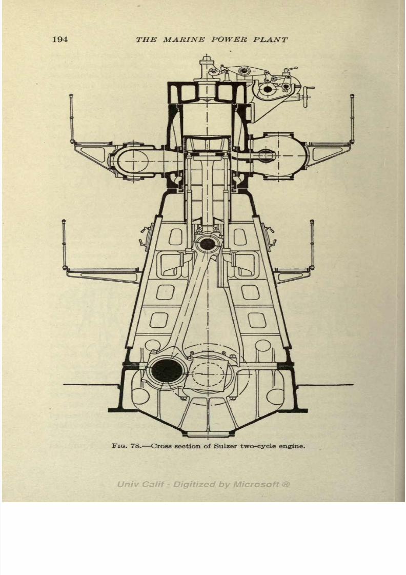
8/3/2019 Marine Power Plant Chaprich
http://slidepdf.com/reader/full/marine-power-plant-chaprich 206/335
194 THE MARINE POWER PLANT
FIG. 78. Cross section of Sulzer two-cycle engine.

8/3/2019 Marine Power Plant Chaprich
http://slidepdf.com/reader/full/marine-power-plant-chaprich 207/335
THE DIESEL ENGINE 195
the engines have been increased. Revolutions over 250 are
not recommended for commercial work and revolutions of 375,
while used in submarine engines, are only maintained for short
runs.
143. The Sulzer Two-Cycle Engine. This engine, built by
by Sulzer Brothers of Winterthur, Switzerland, is one of the
most reliable two-cycle engines built and has many valuable
and novel features in its design. The Sulzer engine is of the
port scavenging type. A diagram of the engine cycle is shown
in
Fig.77. Two
scavenging portsare
provideda lower one
which is uncovered by the piston in its downward stroke and
an upper port fitted with a valve (Fig. 77 shows a poppet type
scavenging valve but the latest practice is to use a rotary valve
as shown in Fig. 78). The valve in the upper port does not open
until the lower one has been uncovered, but it stays open (Fig.
77) after the exhaust port and lower scavenging port have been
closed by the upward movement of the piston. This allows a
larger supplyof fresh air
to be blowninto
the cylinder thanwhen only one scavenging port is used. Thus the cylinder is
filled with a larger supply of air and can develop more power per
stroke because of the higher m.e.p. A cross-section of the
engine is shown in Fig. 78. The use of the port scavenging
system eliminates all the valves in the head except the fuel
valve and air starting valve. These are fitted in a common
casing at the center of the cylinder head, thus requiring only
one opening through the head casting. This is an importantfeature as it greatly simplifies the jacketed head casting a
constant source of trouble in the development of the Diesel
engine. Piston cooling is carried out by the use of telescoping
pipes clearly shown in Fig. 78.
In the smaller powers the engine is fitted with a double acting
scavenging pump while, for powers above 1,000 S.H.P., electric
driven turbo-blowers are used. Figure 79 shows a view of a
Sulzer 1,350 S.H.P. engine fitted for using the motor driven blowerfor scavenging. Figure 80 shows an engine room arrangement
for a twin screw ship with two 4,500 S.H.P. Sulzer engines.
Due to the absence of exhaust, inlet and air scavenging valves
a two-cycle port scavenging engine, similar to the Sulzer engine,
can operate successfully on the inferior and heavy asphaltum
oils and Mexican fuel oils as pointed out in Art. 147.
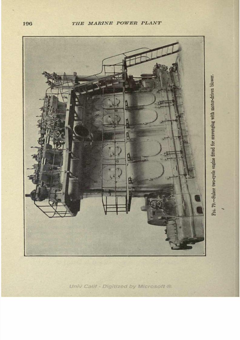
8/3/2019 Marine Power Plant Chaprich
http://slidepdf.com/reader/full/marine-power-plant-chaprich 208/335
196 THE MARINE POWER PLANT
fo

8/3/2019 Marine Power Plant Chaprich
http://slidepdf.com/reader/full/marine-power-plant-chaprich 209/335
THE DIESEL ENGINE 197

8/3/2019 Marine Power Plant Chaprich
http://slidepdf.com/reader/full/marine-power-plant-chaprich 210/335
198 THE MARINE POWER PLANT

8/3/2019 Marine Power Plant Chaprich
http://slidepdf.com/reader/full/marine-power-plant-chaprich 211/335
THE DIESEL ENGINE 199
144. Cammellaird-Fullagar Engine. This engine is of the
Junkers two-cycle type using opposed pistons. While most
opposed engines require three cranks per cylinder, making a
complicated mechanical design, the Cammellaird-Fullagar engine
uses only two cranks for each pair of cylinders. Thus the ad-
vantages of the opposed piston type are secured without the
disadvantages.
As shown in Fig. 81, the cylinders are arranged in pairs.
Each cylinder is open at both ends and fitted with two pistons.
The upper piston A of one cylinder is connected to the lower
piston B of the second cylinder by diagonal tie rods; and the
upper piston C of the second cylinder is connected to the lower
piston D of the first cylinder in a similar manner. When com-
bustion takes place in the first cylinder the pistons A and Dare forced apart, A moving upward and D downward. The pis-
tons in the second cylinder come together on the compression
stroke as A and D separate on the working stroke. Thus crank
E is forced down and crankF,
which is at 90 to
E,is forced
up.The fuel spray valves are placed in the center of the cylinder
between the two pistons. The exhaust ports are placed at the
top of the cylinder and are uncovered by the upper piston; the
scavenging air is admitted through a complete ring of ports
located at the bottom of the cylinder which are uncovered by the
lower piston. Tliis allows the scavenging air to transverse the
entire cylinder space and insures excellent scavenging. The
scavenging pumpsare
rectangularin cross-section and are
located on top of the cylinders.
The advantages claimed for this engine, many of which are
inherent with the Junkers type, are as follows:
1. Piston loads balanced so that no stress comes on columns or cylinders.
2. Cylinder heads with all their complications eliminated.
3. One-third to one-half the fore and aft space required for four-cycle
engine of same power.
4. Good balance due topistons moving
in
oppositedirections.
5. Rate of expansion of gases double that for other engines of same
piston speed, allowing operation at low r.p.m.
6. Excellent scavenging.
145. Burmeister and Wain Engine. This engine is the best
known of the four-cycle types, is built by a large number of
licensees, and has been used in motorships more widely than
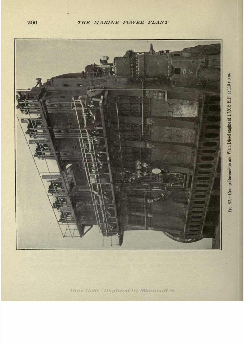
8/3/2019 Marine Power Plant Chaprich
http://slidepdf.com/reader/full/marine-power-plant-chaprich 212/335
200 THE MARINE POWER PLANT

8/3/2019 Marine Power Plant Chaprich
http://slidepdf.com/reader/full/marine-power-plant-chaprich 213/335
THE DIESEL ENGINE 201
any other make. Figure 82 shows a Burmeister and Wain
engine of 1,750 S.H.P. at 115 r.p.m. built by the William
Cramp& Sons S. & E. B. Co. of Philadelphia. This engine is of the
cross-head type and has six cylinders 29 1/8 in. bore by 45 1/4
in. stroke. Figure 83 is a
cross-sectional view through
the engine and shows clearly
the piston and cross-head
construction, piston cooling
arrangementand valve
gear.Burmeister and Wain have
also developed a long stroke
engine of 85 r.p.m. for single
screws in which the stroke-
bore ratio is slightly over 2.0.
The standard designs for twin
screw ships has a stroke-bore
ratio of about 1.5.
146. Nelseco Engine. The
New London Ship & Engine
Co. has developed a small
power type of four-cycle
Diesel engine. Standard com-
mercial engines of four, six
and eight cylinders are built
in horsepowers ranging from60 to 600 s.h.p. and r.p.m.
ranging between 200 and 350.
This company also has built a
large number of submarine engines of from 700 to 1,000 s.h.p.
which run at 350 and 375 r.p.m. Figure 84 shows a section
through the Nelseco engine. The inlet, exhaust and spray
valves, camshafts and valve gear are clearly shown. This
engine is typical of a large number of Diesel engines of small
powers and moderately high r.p.m. that are available for the
propulsion of small craft and for units in larger ships using Diesel-
electric drive.
147. Present Day Trend and Practice. Table XII shows the
sizes of Diesel engines used in some of the largest motorships.
Nearly all motorships have been built with twin screws because
FIG. 83. Cross-section of B. & W.engine.

8/3/2019 Marine Power Plant Chaprich
http://slidepdf.com/reader/full/marine-power-plant-chaprich 214/335
202 THE MARINE POWER PLANT
Diesel engines of large power have not been available and because
shipowners have considered the Diesel engine too precarious to
install a single engine. With the increase in horsepower of
Diesel engines and its greater reliability, the single screw motor-
ship will no doubt predominate.
A. Piston.
B. Inlet valve.
C. Inletmanifold.
D. Cylinder.
E. Fuel valve.
F. Crank shaft.
G. Exhaust valve.
H. Exhaust manifold.
FIG. 84. Cross-section of Nelseco Diesel engine.
Diesel engines of 2,700 S.H.P. are already in successful opera-
tion and larger sizes are already designed and firms are ready
to undertake their construction. The twin screw, 16 to 17 knot
motor liner of 12,000 S.H.P. will probably appear in the near
future.

8/3/2019 Marine Power Plant Chaprich
http://slidepdf.com/reader/full/marine-power-plant-chaprich 215/335
THE DIESEL ENGINE 203
Diesel engines of high r.p.m. and double acting engines so
far have not been successful but the double acting engine will
no doubt be developed.
Today the four-cycle engine predominates; but because of its
lighter weight and smaller fore and aft length the two-cycle
engine is bound to be used more and more, especially in ships of
moderately high speeds.
The one great drawback to the Diesel engine today is that it
requires a lighter and more expensive grade of fuel oil. Prices
of Diesel engine oil vary from 25 to 100 per cent morethan steamship "fuel oil." When the cost is twice that of fuel
oil the advantages of cost, space, and economy are all in favor
of the geared turbine ship.
Heavy tar oils have been successfully used with Diesel engines
on shore by heating the oil, but such a system is not feasible on
shipboard. The two-cycle engine, especially the port scaveng-
ing type, is better adapted for using the heavier fuel oils because
of the absence of valves.
The great necessity in future development with Diesel engines
is to make them available for burning the heavier Mexican and
Texas fuel oils and residual oils. This has already been accom-
plished to a limited extent by heating the fuel with the exhaust
gases.
148. Semi-Diesel Engines. Semi-Diesel engines operate on
the Otto cycle with constant volume admission and use a com-
pression pressure of about half that used in the Diesel engine.
They obtain their name because they use a heavy oil fuel, the
same as used in the Diesel engine.
Because of their low compression pressure the heat of com-
pression is not sufficient for igniting the fuel; hence the semi-
Diesel engine must rely on hot bulbs or hot plates for assisting
in the ignition. In starting a torch must be used to heat the
hot bulb or hot plate.
In the most recent designs the hot bulb and starting torch
have been replaced by electrically heated starting plugs. These
plugs are used only for a few minutes when starting up, and after
warming up the engine depends upon some heat retaining part
for igniting the fuel. This gives a safer and more satisfactory
engine than those using starting torches.
The advantage of this type of engine is its ability to burn Diesel

8/3/2019 Marine Power Plant Chaprich
http://slidepdf.com/reader/full/marine-power-plant-chaprich 216/335
204 THE MARINE POWER PLANT
g SiI*
3* 3
fe fc .S
li
bel
I
I
"C Am
hnBrit
^3
Mau
Amer
. fc
1 .9 .9 dl -a
-.ga-
03 0) 03 03 03
-a .s d d = 4 j, 1 s s
.
=
.
ll
1 : 1 s

8/3/2019 Marine Power Plant Chaprich
http://slidepdf.com/reader/full/marine-power-plant-chaprich 217/335
THE DIESEL ENGINE 205
engine fuels and the absence of the bad features of the Diesel
engine caused bythe
high compression pressures.The
greatobjection to the engine is the methods required for starting
when cold.
Semi-Diesel engines are generally built in small powers up to
about 500 h.p. and are very reliable and satisfactory for small
craft and auxiliaries where small power is desired.
Among the best known makes of semi-Diesel engines are the
Bolinders, Price-Rathbun, Beardmore and Vickers-Peters. The
Doxford engine recently brought outin
powers up to 3,000I.H.P. uses a low compression pressure of 300 Ibs. and has pistons
with thick "heat retaining" heads. The engine is started by
steam and uses solid injection with an oil pressure of 9,000
Ibs. per square inch. This engine is essentially of the semi-
Diesel type.
149. The Still Engine. This is a combination Diesel and
steam engine, devised to increase the thermal efficiency over
that of the Diesel engine. The heat ordinarily rejected in the
jacket water and to the exhaust is used to produce steam and
about 8 per cent of this heat is converted into useful work,
increasing the B.H.P. of the engine about 30 per cent.
A diagram of the Still engine is shown in Fig. 85. In its
present form the engine is double acting with the Diesel cycle
working on top of the piston and the steam cycle below the
piston. The water jacket is connected in a circuit with the
boiler and an exhaust generator as shown in Fig. 85. Thecooling water enters and leaves the jacket at a constant tempera-
ture corresponding to the pressure of the steam in the boiler.
The heat absorbed by the jacket water surrounding the com-
bustion cylinder is used to convert the water into steam at
constant temperature. In other words, the heat of combustion
that radiates through the walls is transferred into latent heat
of steam (7*1). The steam thus generated passes to the boiler.
The function of the boiler is to produce steam for warming upand starting the engine and to augment the supply generated in
the jackets if the jacket supply is not sufficient for the steam
end of the cylinder.
The boiler feed water is circulated through the jacket as shown
in Fig. 85. The feed water is taken from the feed tank by the
feed pump as in all steam plants and is delivered at about 100

8/3/2019 Marine Power Plant Chaprich
http://slidepdf.com/reader/full/marine-power-plant-chaprich 218/335
206 THE MARINE POWER PLANT
to a feed heater or exhaust generator where it absorbs the heat
in the exhaust gases. The temperature of the feed water is
thus raised from 100F. to between 350 and 450F. and the
exhaust gases are reduced from 900 to 150F. The feed
water then enters the jacket where it is converted into steam by
the heat of combustion.
The steam from the boiler enters the lower part of the cylin-
der and acts on the piston in practically the same manner as
STILL THERMAL CYCLE:
FIG. 85. Diagram of Still engine.
in a steam engine and is then exhausted to the condenser. Cyl-
inder condensation, which is a large loss with the ordinary
steam engine, is practically eliminated in the Still engine because
of the heat received from the combustion of the gases in Diesel
end.
During compression of the air on the Diesel side of the piston
the air charge absorbs heat from the cylinder walls because of
the high temperature in the jacket. With the straight Diesel
engine the transfer is in the opposite direction, due to the cold
circulating water. One result of this is that the required com-
8/3/2019 Marine Power Plant Chaprich
http://slidepdf.com/reader/full/marine-power-plant-chaprich 219/335
THE DIESEL ENGINE 207
pression pressure is less in the Still engine than in ordinary
Dieselengines.
The advantages due to the interaction of the combustion and
steam cycles are summarized by F. E. D. Acland in a paper
before the Royal Society of Arts as follows:
1. The mean temperature of the cylinder walls is higher than in ordinary
engines, the cooler parts being maintained at a higher, the hotter parts at
a lower temperature.
2. The piston is cooler, owing to the expansion of the steam behind it.
3. The heat efficiency of the combustion cycle is augmented owing to
the walls being at a higher and constant temperature, and is in proportion
to the rise in temperature of the jacket water.
4. Fractional losses are reduced by the higher temperature, and by the
steam overcoming the inertia of the reciprocating masses at the lower dead
center.
5. The mechanical efficiency of the whole engine is higher than that
obtainable in a normal engine of similar type.
6. The steam, expanding as it does in a cylinder hotter than itself,
gives an indicator diagram larger than that theoretically obtainable under
ideal conditions in an ordinary steam engine.
7. Twenty-nine per cent of additional brake horsepower is added to
the shaft of the engine, without increase in the fuel consumption. (Steam
not condensed.)
8. Forty per cent is added with condenser used. (Air pump separately
driven.)
9. The I.H.P. due to steam appears as B.H.P. added to the shaft, all the
mechanical losses having already been accounted for in measuring the
combustion B.H.P.
Besides the merits listed above the two-cycle Still engine has
the following advantages:
1. Fuel consumption 10 to 20 per cent lower than the Diesel engine.
2. Absence of cold circulating water causing large temperature dif-
ference and trouble with cylinder and head castings.
3. Absence of cylinder condensation in steam end.
4. Lower compression pressure.
5. Absence of air starting, circulating, and piston cooling system.
6. Absence of exhaust valves and gear.
7. Increased horsepower for a given bore and stroke.
8. Possibility of overload by forcing steam boiler.
9. Maneuvering at low r.p.m. is possible.
10. High temperature range 2,000 to 150F. (Carnot efficiency).
Trials with a single cylinder two-cycle Still engine were
carried out during 1921 by Scott's Shipbuilding & Engineering

8/3/2019 Marine Power Plant Chaprich
http://slidepdf.com/reader/full/marine-power-plant-chaprich 220/335
208 THE MARINE POWER PLANT
Co., Greenock, Scotland. Owing to the fact that the experi-
mental engine had only one cylinder, it was necessary to pro-
vide a small auxiliary H.P. steam cylinder, the lower end of the
main Still cylinder serving as a L.P. steam cylinder. In an actual
installation where several cylinders are used the lower part of
Combustion Cylinder.Reinforcing Steel Hoop.Scavenging Blower.Combustion Exhaust Pipe Jacketed
by Boiler Water.Exhaust Generator.Feed Water Heater.Fina Combustion Exhaust to Atmos-
phere.Boiler.
Main Steam Pipe.Steam Inlet and Exhaust Valves.Steam Cylinder.
Steam Exhaust to Condenser.Condenser.
14. Suction Pipe to Air Pump.15. Air Pump.16. Feed Pump.17. Delivery Pipe to Feed Heater.18. Circulating Water, Boiler to Exhaust
Generator.19. Circulating Water, Exhaust Generator
to Cylinder Jacket.20. Circulating Water and Steam; Jacket
to Boiler.
21. Auxiliary Oil Burner.22. Condenser Circulating Pump.23. Oil Fuel Injection Pump.
24. Oil Fuel Delivery to Injection Valve.25. Injection Valve.
FIG. 86. Section through Still engine."1
one can be used as a H.P. cylinder and the lower part of another
as a L.P. cylinder, thus obviating the use of an auxiliary cylinder.
All the auxiliaries except the scavenging air pump were driven
off the main engine in these trials. A diagrammatic view of this

8/3/2019 Marine Power Plant Chaprich
http://slidepdf.com/reader/full/marine-power-plant-chaprich 221/335

8/3/2019 Marine Power Plant Chaprich
http://slidepdf.com/reader/full/marine-power-plant-chaprich 222/335
210 THE MARINE POWER PLANT
eliminated and the small boiler employed with the Still engine
would generally be required on a Diesel ship for heating purposes.
It would seem that the claims of the inventor are borne out
by the recent trials and the engine has excellent possibilities
for marine propulsion.

8/3/2019 Marine Power Plant Chaprich
http://slidepdf.com/reader/full/marine-power-plant-chaprich 223/335
CHAPTER XIV
COMPARISON OF TYPES OF PROPELLING MACHINERY
150. General. Considerable difference of opinion exists today
on the proper type of machinery to use for ship propulsion. The
installation to give the most economical performance in servicedoes not necessarily mean the one showing the lowest fuel con-
sumption, for hand in hand with a study of fuel and steam con-
sumption must go a study of capital charges, depreciation, cost
of maintenance, weight, space occupied, r.p.m. and propeller
efficiency, possibilities of breakdown and the general feasibility
and reliability of the installation as a whole. As an example, a
case is on record where a quadruple expansion (land installa-
tion) showing excellent fuel consumption was replaced by an-other engine because of the high overall maintenance cost.
Here is a case where the low fuel consumption was outweighed
in actual practice by other considerations.
Another point that should not be overlooked is the inter-
relation of the efficiency of the power plant with the operating
efficiency of the ship as a whole. Obviously, if the repairs or
overhauling of a particular unit of a ship's power plant, or the
ability to obtain fuel, prolonged the ship's stay in port over
that necessary for discharging and loading the cargo, it would
be poor judgment to install such a unit or adopt a particular
fuel, no matter what gain in fuel economy resulted. For a
slow or medium speed cargo ship the fuel cost is not a large
proportion of the total operating expenses, and hence a reduction
in fuel consumption should not be accomplished at the expense
of some more important factor in the operating charges.
The power plant and fuel have another relation to the ship
as a whole, in that they both affect the cubic feet of cargo
space, the tonnage measurement, and the net deadweight capa-
city. We should not lose sight of the fact that a reduction in
steam consumption is accompanied by a reduction in the size
(and cost) of the boilers, piping, auxiliaries and bunkers which
211

8/3/2019 Marine Power Plant Chaprich
http://slidepdf.com/reader/full/marine-power-plant-chaprich 224/335
212 THE MARINE POWER PLANT
in turn increase the carrying capacity of the ship. So complex
is the problem that no exact solution is possible the best that
can be done is to give proper weight to all the factors involved.
The tendency in the past has been too conservative in regard
to innovations and improvements in a ship's power plant.
There has been some justification for this, for if troubles arise
with new types of machinery at sea the engineer cannot call on
the manufacturer for help and assistance as in a land installa-
tion, but must make his own repairs and solve his own problems.
Further, when a ship is at sea the superintending engineer does
not have access to the plant as in a land installation and the
chief engineer is thrown absolutely on his own resources. Abreakdown of a ship's machinery at sea is always a more serious
affair than in a power plant on shore; at times it might seriously
endanger the ship. During the war marked advances were
made in marine engineering and much of the conservatism has
been swept aside and many things almost impossible a few years
ago are today larger adopted. Still, there is a great deal of
conservatism left among shipowners, as the failure to adopt
Diesel engines and the continued use of the Scotch boiler engines
bear witness.
151. Types. In the selection of machinery for a merchant
ship, we have the following types to choose from:
1. Triple expansion reciprocating engines.
2. Quadruple expansion reciprocating engines.
3. Direct connected turbines.
4. Combination machinery triple expansion engines and L.P. turbine.
5. Geared turbines.
Single reduction 1 : 5 to 1 : 10.
Double reduction 1:25 to 1:35.
6. Electric drive.
7. Diesel engines.
(a) Two- or four-cycle.
(b) Solid injection; air injection.
8. Diesel electric drive.
v). Still engine combination of steam and Diesel cycles.
All of these types have virtues and defects and a selection
cannot be made on a few points alone.
The important factors to be considered in a selection are:
1. R.p.m. and propeller efficiency.
2. Fuel consumption.

8/3/2019 Marine Power Plant Chaprich
http://slidepdf.com/reader/full/marine-power-plant-chaprich 225/335
COMPARISON OF PROPELLING MACHINERY 213
3. Weight, and space occupied.
4. Capital charges, including maintenance, repairs and depreciation.
5. General reliability.
6. Time required in port for overhauling and repairs.
For a low speed cargo ship of moderate power, high propeller
efficiency requires low r.p.m. With the exception of the direct
connected turbine, all the types mentioned can be designed for
revolutions from 80 to 130.
With direct connected turbines the high r.p.m. necessary for
good turbine efficiency, reasonable weight, and size are detri-mental to propeller efficiency; hence this type of machinery has
practically disappeared from ship propulsion and will not be
considered here. The last noteworthy installation was on the
S.S. "Lusitania" and S.S. "Mauretania," which were ships of
25 knots speed with the propeller running at 180 r.p.m.
152. The Reciprocating Engine. With the exception of the
four-cycle Diesel engine the reciprocating engine as represented
by the three and four cylinder triple expansion and the quadrupleexpansion types is the heaviest and most bulky prime mover
used for ship propulsion. The marine reciprocating engine
always shows a higher steam consumption than the turbine.
This is due partly to the lower steam pressure, lower superheat
and lower vacuum used with the reciprocating engine and partly
to the lower efficiency ratio which is inherent with the recipro-
cating engine. It was pointed out in Art. 90 that it was inad-
visable to carry more than 27 or 27 1/2 in. c?r vacuum with a
reciprocating engine while with a turbine 29 in. is possible.
Reciprocating engines could, however, carry as high a steam
pressure and superheat as is used with turbines, but generally
when the former type of machinery is used the same conserva-
tism that leads to the adoption of the reciprocating engine
results in the use of lower steam pressures and generally no
superheat. We thus find the turbine working between more
extreme limits and hence having a larger Rankine efficiency.
The efficiency ratio of the reciprocating engine is lower than
a turbine even when both prime movers are working between
the same limits. This is due to the large losses by condensation
and leakage in the reciprocating engine. The engines of the
U.S.S. ''Delaware," which were exceptionally well designed
engines, had an efficiency ratio of only .55; and the S.S."Rampo
"

8/3/2019 Marine Power Plant Chaprich
http://slidepdf.com/reader/full/marine-power-plant-chaprich 226/335
214 THE MARINE POWER PLANT
with a quadruple expansion merchant engine showed an effi-
ciency ratio of only .597. Geared turbines, on the other hand,
will invariably show efficiency ratios of .60 and .65 (see Art.
184). Further, the turbine will continue to show good economyafter long service while the efficiency of the reciprocating engine
will fall off rapidly due to the wear of the numerous moving
parts such as pistons, valves, cylinders, cylinder liners, etc.
Some land installations with low r.p.m., large ratio of expan-
sion, and fitted with jackets, reheaters, etc,, have shown excel-
lent economy as indicated in Table IX. This table shows effi-
ciency ratios as high as .70 and .74 for stationary reciprocating
engines. Such units would not be at all feasible on shipboard
on account of weight and space requirement. If steam and
fuel consumption, weight and space were our only criterion in
selecting machinery the reciprocating engine would receive
little consideration today. The triple expansion engine, how-
ever, is an installation of proven reliability, repairs can generally
be made in any part of the world, and marine engineers arefamiliar with the unit. The geared turbine and electric drive,
on the other hand, are new and in some respects untried installa-
tions. Repair bills and the time lost in overhauling these units
when operated by inexperienced crews may more than offset
the advantages of lower steam consumption and reduced
machinery space.
The four cylinder triple expansion engine with the improve-
ments in design such as were used in the last reciprocating en-
gined ships of the U. S. Navy has much to recommend it for
certain low powered cargo ships, such as tramps, on account of
the character of the engine room force often available and possi-
bilities of repairs in out-of-the-way ports. There is no doubt,
however, that too many reciprocating steam engines are being
installed today, especially with the advantages offered by the
Diesel engine. The quadruple expansion engine shows better
economy than the triple expansion engine, but its first cost is
greater and it requires a longer fore and aft space. Thus, while
there is a reduction in annual coal bills and a reduction in bunker
and boiler space, there is a loss of cargo space on account of the
longer engine room required and an increase in capital charges
due to greater first cost of the engine. Unless the ship is of
sufficient size and the voyage long enough to show a fair increase

8/3/2019 Marine Power Plant Chaprich
http://slidepdf.com/reader/full/marine-power-plant-chaprich 227/335
COMPARISON OF PROPELLING MACHINERY 215
in annual profits due to reduction in fuel costs and bunker and
boiler space as offset against increased capital charges and loss
of cargo space (due to length of engine), the quadruple expansion
engine is not to be recommended. As a rule the four cylinder
triple expansion engine is to be preferred in place of a quadruple
expansion engine.
153. Combination Machinery. Combination machinery at
one time offered great possibilities in reduced steam consumption
and would no doubt have been widely adopted except for the
introduction of the geared turbine. This type of machinery
consists of a three screw arrangement with reciprocating engines
on the wing shaft, exhausting to a low pressure turbine on the
center shaft. The steam consumption of this arrangement is
nearly as good as that of the geared turbine. This is due to
the high efficiency of the reciprocating engine at high pressures
and the turbine and low pressures. The noteworthy installa-
tions are the S.S. "Otaki," S.S."Olympic" and S.S. "Rocham-
beau." The machinery requires a larger space than recipro-
cating engines because of the necessity of placing the turbine
on the center shaft aft of the wing engines. It was found in
the "Otaki" installation, however, that the loss in cargo space
was offset by the reduction in bunker and boiler space. There
resulted a considerable net gain due to reduced coal consump-
tion. The "Minnekahda" of the Red Star line, built as late
as 1917, is fitted with this type of machinery.
154. Geared Turbine and Electric Drive. From the fore-
going it appears that the choice of a steam installation narrows
down to the geared turbine and the electric drive. These two
types of machinery do not differ greatly from one another in
steam consumption, weight, and space occupied. Certainly,
the small difference in these factors is not enough to have an
influence in the selection of one or the other for a cargo ship.
Both can reduce the propeller revolutions down to a reasonable
value. The little difference existing is in favor of the
gearedturbine which can reduce the r.p.m. down to a value as low as
is desired while the lower limit for a motor of less than 3,000
S.H.P. is about 100 r.p.m.1 The efficiency is also slightly in favor
of the geared turbine which has an efl&ciency of 95 per cent for
the double reduction gears against 91.5 per cent for the combined
efficiency of the generator and motor. However, there is a

8/3/2019 Marine Power Plant Chaprich
http://slidepdf.com/reader/full/marine-power-plant-chaprich 228/335
216 THE MARINE POWER PLANT
small loss due to windage in the reversing turbine of the geared
installation which reduces the output of this installation. The
netresult is that the
gearedinstallation
requires about2^
percent less shaft horsepower than electric drive.
1 To this should
be added a slight possible gain in propeller efficiency if lower
r.p.m. are adopted with the geared turbine.
Ease of control and reversing, and economy at reduced speeds
are greatly in favor of the electric drive. Also, due to the fact
that the electric drive requires no reversing element, a higher
initial steam temperature can be carried which allows greater
possibilities in economy by using higher steam pressures and
superheat. Because of the constant speed inherit with the
synchronous motor, racing of the propeller in heavy weather
is impossible with the electric drive when synchronous motors
are used. Ships equipped with this type of machinery have
shown almost constant r.p.m. in a heavy sea. For this reason
the ship fitted with electric drive would show better economy
and outdistance the geared turbine ship in heavy weather.
The electric drive has been proven beyond all dispute to be
the ideal machinery for naval vessels where ease of handling
during maneuvering is essential and where good economy at
cruising speeds is required. These merits, however, do not
appear to be pertinent for merchant ships where continuous
duty at full power and a minimum amount of maneuvering are
involved.
The claim has been put forward for the electric drive that it
eliminates the shaft alley, but this is only accomplished by a
reduction in cargo space caused by the motor compartment aft.
It is also very poor practice to place a piece of machinery in a
compartment that has no communication with the engine room
except by going on .deck.
The electric drive has one advantage over the geared turbine
that may eventually prove of more importance than it does
today namely, the life of the installation. This turbine will
last indefinitely and will require little attention except for the
bearings, but the gears will probably have to be replaced from
time to time due to wearing, pitting, etc. The electric machin-
ery, however, will probably outlast several sets of gears. This
may prove an important factor in operating costs.
lMar. Eng., Dec., 1919, p. 817.

8/3/2019 Marine Power Plant Chaprich
http://slidepdf.com/reader/full/marine-power-plant-chaprich 229/335
COMPARISON OF PROPELLING MACHINERY 217
During the haste and rush of the war a number of geared
installations fell down due to poor workmanship; others failed
because of incorrect design caused by a lack of experience.
Perhaps the largest amount of trouble, and that which has
caused such a lot of prejudice and hesitation about adopting
geared turbines, has been due to the inefficient handling on
shipboard by inexperienced crews.
With the careful workmanship which is available today, ex-
tended experience in design, and proper attention to the oiling
system after installation, there should be little trouble experi-
enced with this installation. Most of the merchant ships fitted
with double reduction gears today are operating perfectly. A
paper before the Institution of Naval Architects in 1920 by
H. B. Tostevin points out that during the war there were 556
sets of geared turbines in the British Navy, some having been
in operation 6 years. Of these, three were removed for realign-
ment; two were removed and "dressed up" because of noise
andslight wearing;
two others
developedfractured teeth but
were not removed. Surely this is a creditable record.
The ships of the British Navy just referred to are practically
all fitted with single reduction gearing with reductions between
1 : 5 and 1 : 10, the propeller running at 200 to 400 r.p.m.
While revolutions as high as this give good propeller efficiency
with high speed naval vessels, they are not admissible for slow
speed merchant ships. Hence double reduction gearing has
beenadopted
in the merchant service.
A fair comparison, however, shows that the geared turbine
and electric drive are on a par in most respects and are by far
the best choice for steam machinery. If the cost of the electric
drive can be made the same as the geared installation probably
both will be used in the future.
The electric drive in connection with the Diesel engine offers
special advantages for small installations and will be taken up
later in this chapter.As already pointed out, the lower the propeller r.p.m. the
better the efficiency of the propeller. For cargo ships of 10
and 11 knots speed with about 3,000 S.H.P. r.p.m., of about 90
have been adopted with geared turbines. Revolutions lower
than this are even more desirable if suitable gearing can be
secured and the propeller diameter does not become too exces-
8/3/2019 Marine Power Plant Chaprich
http://slidepdf.com/reader/full/marine-power-plant-chaprich 230/335
218 THE MARINE POWER PLANT
sive. We thus see that the introduction of the geared turbine
offers low propeller r.p.m. coupled with light weight as well as
low steam consumption.155. Space Occupied by Machinery. The adoption of im-
proved types of machinery and consequent reduction in the
machinery space may lead to a reduction in revenue, and pos-
sibly a loss, at a place entirely unlocked for namely, in the
port and canal dues which are charged against net tonnage.
The existing rules (1921) for net tonnage measurement allow a
reduction from the gross tonnage of 32 per cent for the ma-
chinery space, provided the actual measurement of this space
is above 13 and under 20 per cent of the gross tonnage. If
this space does not lie between these limits the reduction is
1.75 times the actual space. With improved machinery and
reduced space the percentage might come out 12 per cent. In
this case the rule allows 12 X 1.75 or 21 per cent reduction
instead of 32 per cent.
A. T. Wall, who first directed attention to this fact in a paper
before the Institution of Naval Architects in 1919, cites the
following example: Ship 580 X 70 X 45 ft. with a gross tonnage of
20,000 and fitted with reciprocating engines and Scotch boilers.
The space occupied by engines and boilers works out 14 per
cent, allowing a reduction from the gross tonnage of 32 per cent,
or 6,400 tons. With an allowance of 1,350 tons for crew space,
the total reduction becomes 7,750 tons. This gives a net ton-
nage of 12,250 tons. If the same ship is fitted with turbine
machinery and water-tube boilers the actual space is 10 per
cent, which allows a reduction of 10 X 1.75 or 17.5 per cent
instead of 32 per cent as before. This results in a net tonnage
of 15,150 an increase in net tonnage of 24 per cent with an
actual gain of only 5 per cent in cargo space.
Thus the owner is required to pay tonnage dues on 2,900
additional tonnage by the adoption of more efficient machinery.
While the present tonnage measurements are in force it ap-
pears that the reduction in space brought about by turbine
engines and water-tube boilers might result in a loss instead of
a gain.
This again illustrates the point previously mentioned that
there are many factors which involve the hull as well as the
machinerv installation and that a decision as to the most suit-

8/3/2019 Marine Power Plant Chaprich
http://slidepdf.com/reader/full/marine-power-plant-chaprich 231/335
COMPARISON OF PROPELLING MACHINERY 219
able power plant cannot be given until every influencing factor
is
givenits
proper weight.The geared turbine occupies considerably less space than the
reciprocating engine and about the same space as the electric
drive. A careful comparison recently carried out by the author
between (1) a 3,200 I.H.P. single screw installation consisting of
a reciprocating engine, Scotch boilers and coal fuel; and (2) a
2,950 S.H.P. installation consisting of geared turbine water-tube
boilers and fuel oil, showed that the fore and aft space occupied
by machinery and fuel (including a cross bunker) in the formerinstallation was practically twice that occupied by the latter.
The S.H.P. of the geared turbine was fixed at 92 per cent of the
J.H.P. of the reciprocating engine, and the fuel radius was taken
as 4,000 miles.1
As an illustration of the small space occupied by geared tur-
bine machinery, attention is directed to the S.S. "Andrea Luck-
enbach,"2 which consists of a twin screw geared turbine and
water-tube installation of 6,000 S.H.P. The fore and aft space
occupied by the machinery is only 49 ft. No reciprocating or
Diesel engine installation of similar power could be accommo-
dated in this small space.
156. The Diesel Engine. The superior fuel economy of the
Diesel engine overall other types of prime movers is verymarked.
The fuel consumption of this engine averages about 0.42 lb./
S.H.P., while the very best performance with geared turbines and
water-tube boilers is about 0.90 Ib./S.H.P. per hour. With the
adoption of high steam pressures, superheat, high vacuum, and
the most efficient, oil burning water-tube boilers and geared
turbines, together with the most careful attention to the econom-
ical operation of the whole power plant, the fuel consumption
for a steamship might be reduced to 0.80 Ib./S.H.P. A consump-
tion as low as this, however, would be practically impossible
to maintain for any length of time in service conditions at sea.
The best that can be expected of the steam installation in service
is probably about 1.00 lb. per S.H.P. per hour. The Diesel engine,
however, can easily maintain a consumption of 0.42 Ib./S.H.P.
day in and day out at sea. Hence we can conclude that the
1 See art. 162.
2 An arrangement drawing of this ship is shown in Plate IX of The
Shipbuilding Cyclopaedia.

8/3/2019 Marine Power Plant Chaprich
http://slidepdf.com/reader/full/marine-power-plant-chaprich 232/335
220 THE MARINE POWER PLANT
best steam installation will have a fuel consumption of between
2 and 2.5 times that of the Diesel engine. This is comparing
the very best type of steam machinery with the Diesel engine.
If we extend the comparison to coal burning ships fitted with
reciprocating engines the fuel used will run from 3 to 3.5 times
that of the Diesel engine.
The Diesel engine has now reached the stage in its develop-
ment where shaft horsepowers of 2,500 to 3,000 are in successful
operation. With twin screws, an installation of 6,000 S.H.P. per
ship is possible today. The revolutions of Diesel engines now
in operation in cargo ships range from 85 to 130.
Diesel machinery has the disadvantage when compared with
steam machinery, in that it is considerably heavier and has a
higher first cost. It has the advantage in that it has a fuel
consumption of 1/4 to 1/2 of that of steam installations and the
stand-by losses are practically eliminated. A geared turbine
installation with water-tube boilers will occupy less space than
afour-cycle
Dieselengine, and about the same space as a two-
cycle engine.
Unfair comparisons of Diesel and steam machinery have at
times been published .showing that the Diesel machinery is no
heavier and cost no more per horsepower than steam. These
comparisons, on closer examination, generally reveal the fact
that a Diesel engine with 120 or more r.p.m. is compared to a
steam installation of 70 to 90 revolutions. All comparisons of
cost and weight should, of course, be made at the same r.p.m.
If an actual comparison of ships on a given trade route is
made, and the operating expenses and profits calculated, the
advantages of the motorship generally offset the small disad-
vantages of higher first cost and greater weight per horsepower
provided the motorship does not have to carry fuel for the
round trip and the price of Diesel engine fuel is the same as
"fuel oil."
The objections raised to Diesel machinery by vessel owners
appear to be mostly imaginary; it is a new type of machinerystill in a state of development and subject to breakdowns;
repairs may be difficult to obtain for this new type of machinery,
causing interrupted service and long delays in port with conse-
quent loss in profits; Diesel machinery is easily manhandled in the
hands of an inexperienced crew; there is a scarcity of operating

8/3/2019 Marine Power Plant Chaprich
http://slidepdf.com/reader/full/marine-power-plant-chaprich 233/335
COMPARISON OF PROPELLING MACHINERY 221
engineers and if the Diesel engine is widely adopted ships may be
held
upfor lack of a trained
engineroom
force;breakdowns
and various troubles are frequently reported, and oil cannot be
secured in all ports.
Along with these objections we must bear in mind that men
trained in steam engineering hesitate to give up a well known and
reliable type of machinery for a new and (to them) precarious
type. New types of machinery have always been slowly adopted
on shipboard as the operating engineer must be his own repair
man andthe
engineercannot call on the
manufacturerfor
adviceand assistance as could be done at a power plant on shore. This
last is a strong argument against the rapid adoption of the Diesel
engine for ship propulsion and can only be overcome by provid-
ing well trained and competent operating engineers. Careful
attention on the part of the engine builders to see that the crew
is properly instructed regarding the operation of their engine
and informed of all troubles likely to occur, will go a long- way
to solving this problem.The other objections can be thrown aside because the success-
ful motorship is a demonstrated fact. Those who are competent
to answer assure us that well trained Diesel engineers are avail-
able at all times.
The Diesel engine on account of its small power and large
weight per horsepower cannot be adopted at present for high
powered ships or fast passenger vessels. Also for the same
reason it is not suitable for naval vessels. For the cargo shipand small passenger liners the Diesel engine is an ideal installa-
tion. Its adoption will generally reduce the operating expenses
on account of the reduced fuel costs and increase the annual
profits because of the greater carrying capacity brought about
by the large reduction in fuel weight and space required for
fuel bunkers. The weight and space occupied by fuel for a
Diesel engine is about 25 per cent of that required for a coal
burning and 40 per cent of that for an oil burning steamship(see Chap. VII).
With a short voyage, long port detention or slow speed, the
gain of the motorship is not so pronounced over that of the
steamship on account of the small percentage that the fuel costs
bear to the total operating expenses. It is the combination of
reduced fuel costs and increased deadweight coupled with quick

8/3/2019 Marine Power Plant Chaprich
http://slidepdf.com/reader/full/marine-power-plant-chaprich 234/335
222 THE MARINE POWER PLANT
turn arounds and large number of trips per year that produce
the large gain in profits.
In comparing the fuel consumptions of Diesel engines and oil
burning steamships it must be remembered that the most makes
of Diesel engines require a lighter and more expensive grade of
fuel than steamship "fuel oil." This lighter Diesel oil is more
difficult to procure and is not available in all ports. The price
of Diesel fuel at times is 50 per cent dearer than "fuel oil."
This fact is important and will cut down to a considerable extent
the gain of the Diesel engine over the steam installation. How-
ever, this is probably only a temporary condition that will
pass with a more uniform demand for Diesel fuel and the improve-
ment in Diesel engines so that the heavy and inferior oils can
be used. As already pointed out (Art. 147), the two-cycle port
scavenging type lends itself more readily to the use of the heavier
oils and for this reason will probably be used to a large extent
in the future.
157. Comparison of Two- and Four-Cycle Diesel Engines.The two-cycle Diesel engine is a far more attractive proposition
on paper than the four-cycle, but on the other hand is not so
well known nor so universally used as the four-cycle. It appears
that the real question is not so much a comparison or selection
of cycle as of make of engine. The two-cycle engine is more
difficult to design and is not so well understood and there have
been more frequent breakdowns and troubles with this engine
than with the four-cycle. Hence those arguing for the four-
cycle engine have laid all these misfortunes at the door of the
two-cycle in general instead of the manufacturer in particular.
There are some builders of two-cycle engines, Sulzer Bros, for
example, who have had very good success with two-cycle engines
and apparently have made good most of the claims put forward
for this type.
Most of the attractive features of the two-cycleengine
are not
important enough to warrant the installation of this type in a
cargo ship if there is more probability of trouble than with a
four-cycle engine. The loss of one trip per year or increased
port detention due to frequent repairs will quickly offset all
the small gains brought about by more economical machinery.
Many of the features of the two-cycle engine are advantageous
for passenger ships and ships where weight of machinery is an

8/3/2019 Marine Power Plant Chaprich
http://slidepdf.com/reader/full/marine-power-plant-chaprich 235/335
COMPARISON OF PROPELLING MACHINERY' 223
important item. No doubt the two-cycle engine of the port
scavenging typeis destined to have a
largefield in
the future,especially after further development and experience.
The advantages claimed for the two-cycle engine are:
1. Weight 60 to 65 per cent of four-cycle at same r.p.m. (hence reduced
cost).
2. Space 55 to 80 per cent of four-cycle at same r.p.m.
3. With port scavenging, less complicated head casting and simpler
valve gear.
4. More uniform turning moment; reduced vibrations; shorter crank-
shaft.
5. Absence of exhaust valves.
6. Ability to operate on cheaper and inferior fuels.
The disadvantages charged against the two-cycle engine are:
1. Higher fuel consumption (5 to 10 per cent).
2. Higher lubricating oil consumption.
3. Lower m.e.p.
4. Special means of cooling required on account of great heat effects.
5. On account ofheat, piston cooling
must beadopted
athigh r.p.m.
As pointed out in Chap. XIII there are some makes of two-
cycle engines, notably the Sulzer Bros., to which most of these
objections do not hold.
158. Diesel-Electric Drive. The Diesel electric drive has been
frequently proposed for merchant ships and to some extent
actually fitted in small powers. The merits of this type of
machinery are that one or more high speed Diesel engines driving
electric generators can be installed and the ship propelled by anelectric motor of low r.p.m., and hence high propeller efficiency
obtained without reducing the revolutions of the engine.
Most of the claims brought forward for the electric drive
with steam machinery apply equally well to this type of installa-
tion and, as already pointed out, offer no particular attractions
for cargo ships.
For the electric drive the first cost may be slightly lower than
for direct Diesel drive; the space occupied about the same; the
saving in weight will be small; and the installation will be much
more complicated. Certainly little gain in economy or propeller
efficiency can be claimed and the direct connected Diesel engine
of low r.p.m. will be more reliable in service than the high speed
generating sets.
The Diesel-electric drive, however, does offer many advantages

8/3/2019 Marine Power Plant Chaprich
http://slidepdf.com/reader/full/marine-power-plant-chaprich 236/335
224 THE MARINE POWER PLANT
for naval vessels, yachts and fishing vessels where easy control
and high economy at reduced speed are important factors.
159. Geared Diesel Engines. High speed Diesel engines with
reduction gearing between the engine and propeller have been
used to some extent. An example of this is the S.S."Havelland
"
which has a twin screw installation consisting of two 10-cylinder
1,650 S.H.P. Diesels running at 230 r.p.m. (800 ft. per min. piston
speed) and geared down in a ratio of 2.7 : 1 so that the propeller
runs at 85 r.p.m. The engines used in this case were German
submarine engines built originally to run at 390 r.p.m.; hence
this installation was adopted to make use of engines already on
hand. It does not have any advantages over the Diesel-electric
drive and many of the valuable features of the latter drive are
not obtained by the geared drive.
160. Semi-Diesel Engines. This engine is available up to
powers of 500 S.H.P. and because of its lighter weight, cheaper
cost and its all-round simplicity, it is an ideal propelling unit
for small auxiliary sailing vessels and other craft where thepower required does not exceed 300 S.H.P. The semi-Diesel
engine is used to a considerable extent for an emergency auxiliary
air compressor and generator drive on motorships.
161. Gasoline Engines. This type of internal combustion
engine is used only for small launches and motorboats where
light weight and small horsepowers are essential. Because of
the high cost, and danger in storage and handling of gasoline,
this engine is not used in commercial vessels.
162. Comparison of Seven Types of Machinery Installation
for a Voyage of 4,000 Miles. The following comparison has been
made for ships fitted with :
1. Reciprocating engine, Scotch boilers and coal.
2. Reciprocating engine, water-tube boilers and oil.
3. Geared turbines, water-tube boilers and oil.
4. Four-cycle Diesel engines, (twin screws).
5. Two-cycle Diesel engines, (twin screws).
6. Diesel-electric drive (single screw).
7. Turbo-electric drive (synchronous motor).
A ship with the following characteristics has been used for
each installation:
L.B.P.=418M)".
Beam = 60'-0".

8/3/2019 Marine Power Plant Chaprich
http://slidepdf.com/reader/full/marine-power-plant-chaprich 237/335
COMPARISON OF PROPELLING MACHINERY 225
Depth= 35'-6".
Loaddraft = 26'-0".
Sea speed = 1 1 y% knots.
Load displacement=
14,600 tons.
Block coef.=.78.
Weight of hull and equipment= 4200 tons.
The E.H.P. was calculated from Robertson's data for a longitudinal
coefficient of forebody=
.83, and aftbody= .77.
Proper allowance has been made for struts on the twin screw
ships, for hull efficiencies, changes in wake, and propeller efficien-
cies,as shown in the
following
table. The notes below the table
should be consulted in this connection.
The machinery spaces in all the ship were greater than 13%of the gross tonnage; hence the gross and net tonnage for all the
ships are the same except the coal burning ship which is slightly
less than the others as no fuel is carried in the double bottoms.
The table shows some very interesting results and is worthy
of careful study. Attention is especially invited to the results
shownin lines
23, 24, 30and 31.
As laid out the turbo-electric drive proves itself superior in
space occupied, although the geared turbine and two-cycle Diesel
installations occupy practically the same space. The two cycle
Diesel installation allows the largest net cargo deadweight,
although the difference between the two and four cycle engines
in this respect is not large. The four cycle Diesel installation has
the lowest fuel consumption.
The geared turbine and water-tube boiler installation is the
cheapest, gives nearly the same net cargo deadweight as the
Diesel installation, and allows a volume of cargo space practically
as large as either the two-cycle Diesel or the turbo-electric drive.
The above comparison has been carried through in an impartial
and unbiased manner, the machinery arrangements1 were care-
fully laid out from drawings furnished by the engine builders,
and the weights summarized from authentic data. No doubt in
the hands of other designers the spaces occupied and the machin-
ery weightswouldvarysomewhat ;efficiencies and fuelconsumptions,
however, cannot be varied very much. While variations here and
there might be introduced, the results given above are comparable
1 The machinery arrangements were made by the senior students in the
course in Ship Design at Lehigh University under the direct supervision of
the author.

8/3/2019 Marine Power Plant Chaprich
http://slidepdf.com/reader/full/marine-power-plant-chaprich 238/335
226 THE MARINE POWER PLANT
and shed considerable light on certain aspects of the types of
propelling machinery in use today.
Of course a full and complete comparison must be made of
operating costs on a given trade route to determine which is the
all around most economical type. If authentic figures are avail-
able for the costs of machinery, fuel, lubricating oil, depreciation,
repairs, insurance, etc., operating costs can be quickly worked up
from the data given in the above table.
163. Conclusions. In reviewing the advantages and disad-
vantages of the various types of engines used for ship propulsion
it is seen that the engineer and shipowner are confronted with
a large number of types all of which are in successful commercial
operation. No definite decision can be given as to the best
type, for so many factors are involved that vary with the ship,
the trade route, the cargo to be carried, the type of crew avail-
able, etc. Each case must be carefully studied from the view-
points of efficiency, operating charges and all-round feasibility,
and what is the test type for one ship will not be the best foranother.
It should be borne in mind that much of the published data
and information available has been presented by men advocating
a particular type of propelling machinery and the data are often
biased and unfairly presented.

8/3/2019 Marine Power Plant Chaprich
http://slidepdf.com/reader/full/marine-power-plant-chaprich 239/335
COMPARISON OF PROPELLING MACHINERY 227
ill-
O i i O O t> '
<N O5 lO t (
(M1
<N CO
O CN to to to O O
C^ to to to CO COi i O O i i i (
i-T <N~<N~
ipl-
O *-i\ O^CO CO I
s** CO CO CO CO 00 OS 00 CO CO tO CO '
OStOl^- -OOOOtOOCNt^OOCO M^C^ O 1
O CO
'^Jn^
O Oi I IC
o3 S'o Oiw ra^
O-H to tO to
2 :
?r
as
"o^ : '-3
17 :S^fi
od

8/3/2019 Marine Power Plant Chaprich
http://slidepdf.com/reader/full/marine-power-plant-chaprich 240/335
228 THE MARINE POWER PLANT
co* I-H co* - oToT
-
02 O
S-S
% o i> oCO TH CO 1>.T^
oToT
00 1C
oToT
a
005
8
0505
lOCOCO
0500
_ : : fe :~ : : fc :
5. :.:& :s :J :a :
ilil
SilSgis-
"Ha SiW
s.S
111I-K*
ffi ^ tH
o|a^"s^ll-sllllo
I :i -I ;
^
:^a
: a : a
I :'
s
O5 O i-5 <N COrH<N(N(N (M coco

8/3/2019 Marine Power Plant Chaprich
http://slidepdf.com/reader/full/marine-power-plant-chaprich 241/335
COMPARISON OF PROPELLING MACHINERY 229
Notes on Table
1
All propellers are 3 bladed in this comparison.2Propeller efficiencies from Taylor's charts; mean width ratio = .25. Wake
for single screw ships=
.31; for twin screw = .23.
3 Hull efficiency for single screw ships=
1.05; for twin screw = 1.00.
4Efficiency ratio of S.S. "Rampo" = .58 without superheat; .59 is used in
above calculations due to reduced condensation with 60 superheat.
The S.H.P. of geared turbine installation is measured beyond the gears;
hence efficiency ratio includes loss in gears. For this reason efficiency ratio
of turbine driving generator has been taken as .67 against .63 for geared
turbine. Efficiency of gears taken as 95%; electric transmission as 92%;
1% loss allowed for geared turbine due to windage in astern blading.
5 Steam and fuel consumptions are expressed in Ibs. per S.H.P. per hour in
order to make all the figures comparable. The mechanical efficiency of the
reciprocating engines has been taken as 92% and all consumptions per I.H.P.
have been divided by .92 before recording them in the table. The recipro-
cating engines are fitted with attached air pumps and Kingsbury thrust
blocks.
6 20 Ibs. of coal per sq.ft. G.S. per hour; H.S.^G.S. =36.5.
7 Boiler efficiencies taken as 90% of test values.
8
Port fuel oil allowed as follows: Steamship = 7 tons per day; motorship= 1 ton per day. Days in port per single voyage assumed as 7 days. Coal
in port= 10 ton per day.
9 Where there is an offset in the aft bulkhead the length of a rectangular
compartment of equivalent floor area is given in table.
10 Cross coal bunker included in this length.
"With induction motor, weight= 325 Ibs. /S.H.P.
Calorific value of coal = 14,400 b.t.u. per lb.; oil = 18,800 b.t.u.

8/3/2019 Marine Power Plant Chaprich
http://slidepdf.com/reader/full/marine-power-plant-chaprich 242/335
CHAPTER XV
CONDENSERS
164. General. The object of the condenser is to reduce the
back pressure on the prime mover, thus lowering the final pres-
sure and causing less heat to be discharged in the exhaust. The
Rankine efficiency (#1 #2/#i #2) is improved and an actual
reduction in steam consumption results. The increased expan-
sion of the steam thus brought about causes more heat to be
converted into useful work and a greater horsepower obtained.
Also, the saving of the condensed steam by a surface condenser
is, of course, absolutely necessary on shipboard.
Theoretically,the
greaterthe vacuum the
greaterwill be
the efficiency of the prime mover; but practical considerations
impose limits to which the vacuum can be economically carried.
With a reciprocating engine, 25 to 27 in. is about the limit.
Vacua greater than this cause an undue size for the low pressure
cylinder in order to handle the increased steam volume. The
increase in the capital charges due to the larger cylinders, valves,
air pump and condenser, together with the losses brought about
by increased cylinder condensation and friction of the engine,
will more than offset the gain in economy and horsepower due
to the higher vacuum.
With a turbine, the disadvantages mentioned above for recip-
rocating engines do not exist and the economical limit of vacuum
is probably close to 29 in. The capital charges on equipment
and the cost of producing vacua higher than 29 in. will, as a
rule, more than offset any reduction in steam consumption.
High vacua have the further disadvantage in that the whole
system must be kept in the highest state of efficiency in order
to keep air leakage within a reasonable figure.
The following example shows the theoretical steam consump-
tions for two turbines, both having the same initial conditions
but one operating with 27 1/2 in. and the other 29 in. vacuum.
230

8/3/2019 Marine Power Plant Chaprich
http://slidepdf.com/reader/full/marine-power-plant-chaprich 243/335
CONDENSERS 231
Case I:
Pi (at throttle) =275 Ibs. abs. 100F. superheat.
PZ (in condenser) =29 in.
Theoretical steam consumption = 6.2 Ibs. per S.H.P. per hour.
Case II:
Pi = 275 Ibs. abs. 100F. superheat.
Pz (in condenser) =27 1/2 in.
#!_H2= 370.
Theoretical steam consumption= 6.9 Ibs. per S.H.P. per hour.
Increase in steam consumption of Case II over Case 1 = 11.3
per cent.
165. Air Leakage. The most important factor in producing
and maintaining a high vacuum is the presence of air in the
condenser. The main duty of the air pump is to remove the
air from the condenser at the same rate at which it enters,
and the cost of producing a high vacuumdepends directly
on
the amount of air leakage. The size of the air pump and the
power required to operate it depend more on the amount of
air leakage than on the vacuum carried or the size of the plant.
The possibility of air leakage of course increases with the amount
of vacuum, the size of the propelling unit, and the amount of
feed water used.
Besides increasing the size and horsepower required for the
air
pump,the
presenceof air in a condenser decreases the rate
of heat transfer between the exhaust steam and the cooling
water and thus lowers the efficiency of the condenser. Further,
the presence of air in a condenser lowers the temperature in the
condenser for a given vacuum which causes the condensate to
leave the condenser at a lower temperature. This results in a
lower temperature of the feed water entering the feed water
heater (qz) and may cause a reduced overall efficiency of the
plant.Not only must the condenser and exhaust trunk to the con-
denser be kept tight, but stuffing boxes and glands must be
designed so there is practically no air leakage and the boiler
feed water should be as free of air as possible. A large area
should be given to the feed water tank to facilitate the liberation
of air. Drains and auxiliary exhaust should never be led to

8/3/2019 Marine Power Plant Chaprich
http://slidepdf.com/reader/full/marine-power-plant-chaprich 244/335
232 THE MARINE POWER PLANT
the condenser. An air chamber fitted on the main feed line
between feed pump and the boiler will collect some of the air
in the feed water. This chamber should be fitted with a ventfor removing the air from time to time.
With reciprocating engines there may be considerable leakage
around the L.P. valve and piston rod, as the pressure within the
cylinder is less than that of the air outside. The "steam seal"
adopted in the later ships of the U. S. Navy that were fitted with
reciprocating engines was equipped with this device. The
"steam seal" also prevents the entrance of oil on the L.P. rod
into -the cylinders.
In order to eliminate air leakage around the shaft into the
low pressure stages of turbines, it is customary to fit labyrinth
packing under steam pressure. This causes a small leakage of
steam outward into the engine room instead of an entrance of
air from the engine room into the turbine casing. The Westing-
house Company now fits, in addition to the labyrinth packing, a
water sealed gland for use at high speeds. This gland consists
of a runner similar to that of a centrifugal pump which revolves
in the gland casing. The runner is supplied with fresh water
and a solid annulus of water is maintained at the outer edge,
thus making a seal against air leakage.
When a condenser is in operation the weight of air entering
and leaving in a given time must be the same. If the volume
of this air when it reaches the air pump suction is large and the
air pump is not of proper size to handle it, the vacuum falls
until an equilibrium has been established between the air pumpand condenser. It should be borne in mind that the function
of the condenser is to create the vacuum by condensing the
steam and the function of the air pump is to remove the con-
densed water and air so that the condenser can perform its
proper function at the desired back pressure.
The amount of air to be expected in a condenser can be esti-
mated from the following authorities:
1. Orrok (A. S. M. E., 1910) gives the following figures from
experiments on turbine units of 5,000 to 20,000 kw. :
1 cu. ft. free air per min. (4.5 Ibs. per hour) under best conditions.
15-20 cu. ft. free air per min. (68-91 Ibs. per hour) ordinary leakage.
30-50 cu. ft. free air per min. (136-230 Ibs. per hour) bad leakage.
2. Hodgkinson (Trans. Soc. N. A. & M. E., 1918) states that

8/3/2019 Marine Power Plant Chaprich
http://slidepdf.com/reader/full/marine-power-plant-chaprich 245/335
CONDENSERS 233
3 1/2 cu. ft. of free air per minute is considered good practice
with a 40,000 hp. turbine unit, and 7 cu. ft. is excessive leakage.
3. Kothny (Sterling's Marine Engineers' Handbook) gives
curves showing the air leakage for both turbines and recipro-
cating engines. These data show the air leakage increasing
with the steam consumption which, as already pointed out, is
often the case. For a 5,000 hp. turbine the leakage from these
curves would be 20 Ibs. of free air per hour (4.5 cu. ft. per min-
ute). The data give values consistent with the figures quoted
above.
In large power plants on shore air bells are often fitted to the
discharge of the air pump to measure the amount of air leakage.
While this practice is almost impossible for a ship operating at
sea there is no reason why a test by this method cannot be used
in port.
Air leakage with reciprocating engines is much greater than
with turbines because of the larger number of sliding joints, relief
valves,drains, etc. However, if the steam seal mentioned
above is used on the L.P. cylinder this leakage can be greatly
reduced over the present practice. It should also be borne in
mind that reciprocating engines never carry vacua over 27 or
possibly 27 1/2 in., so that possibilities of leakage and the bad
effects of air in the condenser are not so great as with turbines
where higher vacua are carried. Air leakage of about double
those given above for turbine installations should be allowed
withreciprocating engines.
166. Thermodynamics of the Condenser. For a complete
knowledge of the behavior of air and steam in a condenser it
is necessary to have an understanding of Dalton's Law.
Dalton's Law states:1
1. The pressure of a gaseous mixture (composed of two or
more gases or a gas and a vapor) contained within a vessel is
the sum of the pressures that the separate gases would exert
if each occupied the vessel alone.2. Each constituent behaves as if the others were not present,
that is, each occupies the volume of the vessel and each exerts
its own pressure, corresponding to the temperature within the
vessel.
lThe student is referred to textbooks on thermodynamics for a complete
statement and explanation of Dalton's Law.

8/3/2019 Marine Power Plant Chaprich
http://slidepdf.com/reader/full/marine-power-plant-chaprich 246/335
234 THE MARINE POWER PLANT
A mixture of water vapor, steam, and air in a condenser fol-
lows this law closely. The temperature at any point within
the condenser must be the same for both air and steam andmust correspond to that given in the steam tables for the partial
pressure of the steam. The vacuum or absolute pressure in the
condenser is the sum of the partial pressure of the air and the
partial pressure of the steam.
The following equations express Dalton's Law and give the
relations of volume, pressure, and temperature in a condenser:
If ya = volume of air present.
Y8= volume of steam present.
ta= temperature of air.
t= temperature of steam.
pa=pressure of air.
P, =pressure of steam.
Wa= weight of air present in condenser.
We have:
Pt =
144 Fa
The following example will make clear the application of Dai-
ton's Law to a condenser:
Vacuum in condenser= 29 in.
P t= 1.0 in. Hg. (.489 Ib./sq. in.)
Suppose that the temperature existing in the lower part of
the condenser is 70F. The partial pressure of the steam (P,)
correspondingto a
temperatureof 70 is .739 in.
Hg. (.363 lb./
sq. in.).
We now have:
P t=
.489 Ib./sq. in.
t.= = 70F.
P. = .363 Ib./sq. in.
V, (vol. occupied by 1 lb. steam at .739 in. Hg.) =871 cu.ft.

8/3/2019 Marine Power Plant Chaprich
http://slidepdf.com/reader/full/marine-power-plant-chaprich 247/335
CONDENSERS 235
Pa =P,-P8= (.489-.363)=.126 Ib./sq. in.
_WaRTg _ WaX 53.3X530 _=
144 Fa
=
144X871
Wa= .558 Ib. of air per Ib. of steam. (P,/P*
=.74)
This shows that at this particular place in the condenser the
ratio of air to steam by weight is .558:1.00.
The ratio of the weight of air to the weight of steam in a
condenser varies through the condenser. At the inlet of the
condenser the ratio of air to steam is very small and its effect
is negligible. As the mixture passes through the condenser the
steam is condensed and the weight of water vapor present is
constantly getting smaller while the weight of air remains the
same. Thus the ratio of air to water vapor increases rapidly
until at the air pump suction it is very high.
The partial pressure of the air increases as the steam is con-
densed, becoming a maximum in the bottom of the condenser.
The increase in the partial pressure of the air causes a reductionin the partial pressure of the steam, the total pressure in the
condenser remaining constant. This reduction in the partial
pressure of the steam results in a lowering of the temperature
of the mixture in the lower part of the condenser. As a result
of this lowering of the temperature in the lower part of the
condenser, the temperature of the condensate is reduced, giving
a lower value of qz for the water entering the feed tank. A low
temperature of the condensate leaving the condenser ("hot well
temperature") generally indicates a large air leakage although
it may be caused by too great a quantity or the wrong distribu-
tion of the cooling water. The hot well temperature ordinarily
runs from 3 to 20 lower than the temperature corresponding
to the vacuum.
The total pressure (vacuum) in a condenser is generally
nearly constant from the top to the bottom of the condenser
although there may be a small pressure drop of 0.05 to 0.10 in.
of mercury. A drop in pressure larger than this indicates that
the condenser is poorly designed. The temperature in the con-
denser, however, gradually decreases from the top to the bottom.
As already pointed out the temperature is fixed by the partial
pressure of the steam which decreases as the partial pressure
of the air increases.

8/3/2019 Marine Power Plant Chaprich
http://slidepdf.com/reader/full/marine-power-plant-chaprich 248/335
236 THE MARINE POWER PLANT
An illustration of the changes in temperature that might exist
in a condenser for a 29 in. vacuum is shown in the following
table:
Proportion of air and
steam by weight Temperature, F.
Saturated steam 79 (at condenser entrance)
Air .25 steam 1.00 75
Air .50 steam 1.00 71
Air .75 steam 1.00 67.5
Air 1.00 steam 1.00 64.5 (at air pump suction)
The table on page 237 from a paper by Stuart and Senner in
the Jour. A.S.N.E. 1920 (modified from a paper by Gibson and
Bancel, A.S.M.E. 1915) shows the action of a mixture of one
pound of air and steam in a condenser.
In the table on page 237 the air leakage has been taken as
.0002 Ib. of air per pound of steam. This corresponds to 1.2 cu.
ft.of free air per minute with a steam 'consumption of 27,000
Ibs. per hour.
1.2 cu. ft. free ^r per min. = 1.2 X.076X60 = 5.45 Ibs. per hour.
- = .0002 Ib. of air per pound of steam entering condenser.
^7,uUO
A study of this table will indicate the action taking place in
the condenser. At the entrance of condenser the total pressure
is 1 in Hg. The partial pressure of the air by Dalton's Law is:
.0002X53.3X539 1
657X144
where Va= V8 corresponding to the volume of steam at 79
which is the temperature at the top of condenser.
Wa = pounds of air present per pound of steam.
As the steam is condensed by the cooling water, the weight
of steam decreases rapidly from the top to the bottom of the
condenser. The above equation will show that the partial
pressure of the air (P ) increases as the volume of vapor is
decreased. (Line 3.)
The increase in the partial pressure of the air causes a decrease

8/3/2019 Marine Power Plant Chaprich
http://slidepdf.com/reader/full/marine-power-plant-chaprich 249/335
CONDENSERS 237
I
(M
_
CO
8
00
ss
s
00
00
CO
8
mpion
"p
.p
02

8/3/2019 Marine Power Plant Chaprich
http://slidepdf.com/reader/full/marine-power-plant-chaprich 250/335
238 THE MARINE POWER PLANT
in the partial pressure of the steam (Line 2) since the total pres-
sure is constant. This decrease in Ps causes the temperature
in the condenser to decrease (Line 1) ts = ta = temperature
corresponding to P3 in the steam tables.
Both the increase in the partial pressure of the air and the de-
crease in the condenser temperature from top to bottom cause
the volume occupied by the given weight of air to be decreased.
(Line 7.)1
A decrease in the volume of the air is, of course, necessary in
order to reduce its volume so that it can be handled
bythe air
pump. Thus the bottom of the condenser serves the purpose
of reducing the volume of the air although, as already pointed
out, it results in the lowering of the temperature of the con-
densate. Later on, under the discussion of air pumps, this will
receive further treatment. The greater the air leakage per pound
of steam the greater will be the depression of the hot well tem-
perature. If there is a fall in the total pressure in the condenser
from top to bottom, as is often the case, the temperature will befurther depressed.
167. Heat Transfer. Orrok, who has published by far the
most complete and reliable information on heat transfer in
condensers, gives the following law of heat transfer between
steam and water:
where C7 = b.t.u. transfer per sq. ft. per degree difference perhour.
Ci = cleanliness coef. (varies between 1.00 and .50).
Cz = material coef. (see table).
V =velocity of cooling water in ft. per sec.
P, = partial pressure of steam in condenser.
p t= total pressure of steam and air.
Theair richness factor
(Ps
/Pt)will of course
vary throughoutthe condenser, increasing rapidly at the bottom. Orrok (Mark's
Handbook, p. 1009) gives values of (P,/P t) =0.95-0.97 for tight
condensers. Table XIII shows this ratio varying between 1.00
1 At 59, Pa=
(.488-
.247)= .241 Ibs/sq. in. The volume occupied by the
air that entered with one pound of steam (.0002 Ibs.) is,
.0002X53.3X519
.241X144' 16

8/3/2019 Marine Power Plant Chaprich
http://slidepdf.com/reader/full/marine-power-plant-chaprich 251/335
CONDENSERS 239
and .80 for a temperature drop of 7; and 1.00 to .50 for a tem-
perature drop of 20. Probably the first figures represent thecase for the larger part of the condenser as nearly all the heat
transfer in condensing takes place in the upper part of the con-
denser. Experiments with two pass condensers show that about
3/4 of the heat transfer between the steam and cooling water
takes place in the second (upper) pass of the circulating water.
A mean of 1.00 and .80 gives P,/P<=
.90, which no doubt is too
low a value for the major part of the condensing surface. With
a two pass condenser this air richness ratio would be nearly
unity in the upper pass and .70 to .90 in the lower pass. There-
fore, values in the neighborhood of .95 would appear reasonable
for ordinary leakage. The foregoing brings out clearly the
effect that the presence of air has on the rate of heat transfer.
Table XIV
Material coefficient (C2)
Admiralty 98 Zinc...., 75
Copper 1 .00 Monel metal 74
Aluminum lined 97 Shelby steel 63
Admiralty (oxidized) 92 Admiralty (badly corroded) 55
Aluminum bronze 87 Admiralty (vulcanized inside) . . .47
Cupro-nickel. 80 Glass 25
Tin 79 Admiralty (vulcanized both sides) . 17
Admiralty (lead lined) 79
A study of the formula for heat transfer given above shows
that the rate of heat transfer varies as the square root of the
velocity of the cooling water. Orrok recommends a velocity of
the cooling water (V) of 8 ft. per second for high vacua. If a
higher velocity of cooling water is used a smaller and lighter
condenser can be obtained by reducing the cooling surface. In
high speed craft this, of course, is of importance. Further, a
high water velocity reduces the possibility of incrustation and
scale on the condenser tubes. Velocities as high as 15 ft. per
second are used in high speed ships where weight and space are
important.
With low vacua condensers, where the rise in the temperature
of the cooling water between inlet and discharge is large, due to
the higher temperature existing in the condenser, the speed of
the cooling water will have to be reduced below 8 ft. per second
in order to keep the length of the condenser within reasonable

8/3/2019 Marine Power Plant Chaprich
http://slidepdf.com/reader/full/marine-power-plant-chaprich 252/335
240 THE MARINE POWER PLANT
limits. Velocities of 3 to 5 ft. per second should be used with
condensers where the vacuum is in the neighborhood of 24
to 27 in., unless a three pass condenser is used.
The foregoing is clearly illustrated in Art. 198, and where
computations for condenser design are carried through.
The horsepower of the circulating pump varies as the cube
of the velocity of the cooling water (F3); so high velocities of
FIG. 87. Weir "Uniflux" condenser.
the circulating water, while reducing the size of the condenser,
cost more to maintain.A full explanation and discussion of the methods of obtaining
the amount of circulating water and cooling surface is given
under condenser design in Chap. XIX.
168. Types of Condensers. There are a great many types
and shapes of condensers some with baffles and some with
special tube spacing. Probably one of the best and simplest
types is the pear shaped condenser with regular tube spacing

8/3/2019 Marine Power Plant Chaprich
http://slidepdf.com/reader/full/marine-power-plant-chaprich 253/335
CONDENSERS 241
and without baffles similar to that used by Weir, Fig. 87. Manyclaims are put forward for special shapes and special interior
arrangements of tubes and baffles, but the simple type of pear
shaped condenser has given good, consistent results in practice.
In this shape of condenser the area decreases as the steam is
condensed, thus keeping the same high velocity of the steam
from top to bottom of condenser.

8/3/2019 Marine Power Plant Chaprich
http://slidepdf.com/reader/full/marine-power-plant-chaprich 254/335
242 THE MARINE POWER PLANT
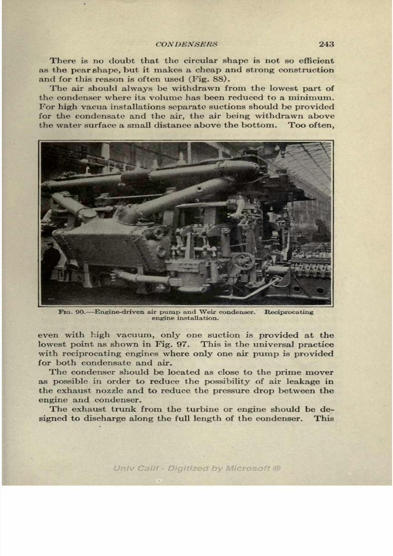
8/3/2019 Marine Power Plant Chaprich
http://slidepdf.com/reader/full/marine-power-plant-chaprich 255/335
CONDENSERS 243
There is no doubt that the circular shape is not so efficient
as the pear shape, but it makes a cheap and strong constructionand for this reason is often used (Fig. 88).
The air should always be withdrawn from the lowest part of
the condenser where its volume has been reduced to a minimum.
For high vacua installations separate suctions should be provided
for the condensate and the air, the air being withdrawn above
the water surface a small distance above the bottom. Too often,
FIG. 90. Engine-driven air pump and Weir condenser,
engine installation.
Reciprocating
even with high vacuum, only one suction is provided at the
lowest point as shown in Fig. 97. This is the universal practice
with reciprocating engines where only one air pump is provided
for both condensateand
air.
The condenser should be located as close to the prime mover
as possible in order to reduce the possibility of air leakage in
the exhaust nozzle and to reduce the pressure drop between the
engine and condenser.
The exhaust trunk from the turbine or engine should be de-
signed to discharge along the full length of the condenser. This

8/3/2019 Marine Power Plant Chaprich
http://slidepdf.com/reader/full/marine-power-plant-chaprich 256/335
244 THE MARINE POWER PLANT
is the universal practice with turbine installations as shown in
Fig. 89 but is not so general with reciprocating engines (see
Fig. 90).
Practically all condensers are of the two pass type. The
first pass of the circulating water should be through the lower
part of the condenser. This gives a large temperature difference
between the steam and the cooling water in the lower part of the
condenser, thus keeping the volume of air to be handled by the
air pump at a minimum. This arrangement has the further
advantage in giving a larger temperature difference in the lower
part where (Ps/Pt) is small and the coefficient of heat transfer
(U) consequently small. Three pass condensers are used where
space is limited either for the condenser or for withdrawing tubes,
and in low vacua installations to reduce the length of the con-
denser. Three pass condensers are objectionable because of the
added turbulence of the water, the baffles required at each end
and because of the fact that the circulating water leaves at the
opposite end from which it enters.
As mentioned in Chap. IV it is very essential that all salt
water be kept out of the feed water. This is especially so when
water-tube boilers are used. Practically the only place that
salt water can leak into the feed water system is in the condenser
where the salt circulating water is passing through the condenser
tubes.
The flat tube sheets at the end of the condenser require staying
on account of the difference of pressure between the inside and
outside of the condenser and leakage is liable to take place where
the stays are secured to the tube sheets. The tubes are generally
held in the tube sheets by screwed ferrules and corset lacing
packing and these tube packings are also a source of salt water
leakage. The practice in recent years in the U. S. Navy has
been to use tubes expanded into the tube sheets. This does
awaywith the troublesome
packing
but requires a curved tube
to take care of expansion. A type of condenser with tubes
expanded in both ends is shown in Fig. 88. This has been taken
from a paper by Dinger in the Journal of the A. S. N. E., May,
1914. The condenser has been curved to allow for expansion and
the stays have been eliminated as the expanded tubes serve
to stiffen the ends. It is claimed that salt leaks have been
practically eliminated with this type of condenser.

8/3/2019 Marine Power Plant Chaprich
http://slidepdf.com/reader/full/marine-power-plant-chaprich 257/335
CONDENSERS 245
The latest practice is to pack condenser tubes with metallic
packingsimilar to that used in
packing pistonrods. A
typeof
spirally wrapped babbitt foil packing, manufactured by the
Crane Packing Co., has recently been used for packing condenser
tubes with excellent success and is being widely adopted both in
the merchant and naval service.
The following table shows the performance of some "Weir-
Uniflux" Condensers:

8/3/2019 Marine Power Plant Chaprich
http://slidepdf.com/reader/full/marine-power-plant-chaprich 258/335
246 THE MARINE POWER PLANT
denser cools the air and reduces its volume so that it can be
handled by the air pump; yet the condensate is withdrawn at
a temperature from 8 to 20 higher than with many types of
SECTION 7HR(/L(m]NMmTCONDWSR.
FIG. 91. Lovekin condenser.
condensers which, of course, improves the overall plant efficiency.
A description of this condenser is given by Mr. Lovekin in a
paper before the Society of Naval Architects and Marine
Engineers, 1920. The following tests on a condenser of this

8/3/2019 Marine Power Plant Chaprich
http://slidepdf.com/reader/full/marine-power-plant-chaprich 259/335
CONDENSERS 247
type are taken from this paper. Attention is especially directed
to Line9, showing
thetemperature
difference between the steam
in the condenser and the cooling water exit.
DATA ON CONDENSER SHIP "CANTIGNY"
No.

8/3/2019 Marine Power Plant Chaprich
http://slidepdf.com/reader/full/marine-power-plant-chaprich 260/335
248 THE MARINE POWER PLANT
constitutes by far the largest part of the exhaust entering this
condenser in port. The heat of vaporization is carried away
by the circulating water for the condensate is already at the
same temperature as the exhaust and no steam is needed for
feed heating.
This practice is extremely poor engineering and the adoption
of electric deck winches will obviate this bad practice. Deck
winches are probably the most inefficient auxiliaries on ship-
board, and this is especially true in cold weather when the
condensation in the deck steam lines and winch cylinders is
FIG. 92. Wheeler condenser with combined air and circulating pumps.
high. Thus we have high steam consumption, heavy con-
densation, and a large part of the heat of the exhaust thrown
away.
If electric driven winches are used the high steam consumption
is eliminated. The current can be furnished by a turbine driven
generator working under a high vacuum and exhausting to the
auxiliarycondenser.
Abetter
arrangementwould be to install
a Diesel generating set for port use. This will eliminate entirely
the use of steam in port and allow the fires to be drawn in all
boilers except when needed for heating purposes. With electric
driven winches shore current may be used when available and
thus allow the ship's whole plant to be shut down. This will
relieve the engine force in port and allow repairs and over-
hauling to be carried out with great facility.

8/3/2019 Marine Power Plant Chaprich
http://slidepdf.com/reader/full/marine-power-plant-chaprich 261/335
CONDENSERS 249
It is thus seen that the auxiliary condenser has very little
useful function in the modern merchant ship. If the surplus of
auxiliary exhaust not needed for feed heating is discharged to
the L.P. stages of the main turbines it should be possible to
eliminate it.
Auxiliary condensers when fitted have a cooling surface of
roughly about 3 per cent of that the main condenser. This is
an arbitrary manner of fixing the size based on previous experi-
ence. The condenser air pump and circulating pump are often
a self-contained unit as shown in Fig. 92.

8/3/2019 Marine Power Plant Chaprich
http://slidepdf.com/reader/full/marine-power-plant-chaprich 262/335
CHAPTER XVI
AIR PUMPS
171. General. The function of the air pump is to remove
the air and condensed steam from the condenser so that the
condenser cancontinously produce
the desired vacuum. With
a low vacuum such as carried with reciprocating engines a
single "wet" air pump is sufficient to take care of the condensed
steam and air leakage. When a vacuum of 28 to 29 in.
is carried, the air pump becomes one of the most important
auxiliaries. The higher the vacuum, naturally the lower is the
pressure in the condenser and the greater is the volume occupied
by a given weight of air. Hence an air pump of large capacity
is required at high vacua to take care of this large volume of
air. As already pointed out, the amount of air to be removed
depends not on the size of the plant or the amount of steam
condensed but upon the amount of air leakage into the system;
although the larger the installation, the greater is the tendency
for air leakage.
By Dalton's Law, it will be remembered that the total pressure
within the condenser is the sum of the air pressure and the steam
pressure. Table XIII shows that at the entrance to the con-
denser the partial pressure of the air is very small, resulting in a
very large volume occupied by the weight of air present a volume
altogether too large to be handled by an air pump. As the
steam is condensed in its passage downward through the con-
denser, the volume occupied by a given weight of steam becomes
smaller and smaller. Hence the ratio of air to steam by weight
becomes larger and larger. Thiscauses an increase in the
partial
pressure of the air and a decrease in the partial pressure of the
steam. As already pointed out in the discussion of condensers,
the reduction in the partial pressure of the steam results in
a reduction of the temperature in the condenser. The increase
in the partial pressure of the air and the decrease in the tempera-
ture cause compression of the air present in the condenser to
250

8/3/2019 Marine Power Plant Chaprich
http://slidepdf.com/reader/full/marine-power-plant-chaprich 263/335
AIR PUMPS 251
a much smaller volume. Table XIII shows this clearly. In this
case the
temperatureof air
pumpsuction has been
depressed20, which is rather higher than necessary.
If the air leakage in a given installation should increase, the
circulating pump must be speeded up and the air pump suction
depressed so that the air present will be reduced in volume
sufficiently to be handled by the air pump installed. If the
air pump cannot handle the increased leakage, the partial pres-
sure of the air will rise, causing the vacuum to fall until a balance
is set
upbetween the air
pumpand condenser.
With high vacua, as a rule, two pumps are used: a "dry air"
pump handling air and water vapor and a "wet air" pump
handling the condensed steam. The best types of dry air
pumps are designed to reduce to the volume of the air either
by decreasing its temperature as in the Weir "Dual" air pumpor by compression as in the Parsons augmentor or "Radojet"
ejector.
The Weir "Dual" air pumpconsists of
two cylinders, oneacting as a "dry" air pump and the other as a "wet" air pump.
The "dry" air pump has an ingenious system whereby cold
water is injected into the cylinder to cool the air and thus
reduce its volume. The Parsons augmentor withdraws the air
by a steam ejector and delivers the air to an augmentor con-
denser where the ejector steam is condensed. The condensate
and air from both the main and augmentor condenser is handled
by a single reciprocating wet air pump.172. Ejector Type of Air Pumps. The steam ejector type of
air pump, of which the Wheeler "Radojet" and Westinghouse-
Le Blanc are examples, is being widely used today and is
giving excellent satisfaction. These use steam jets to withdraw
and compress the air. The steam and entrained air are dis-
charged into the feed tank where the heat in the steam used in
operating the ejector is utilized in heating the feed water. The
condensed steam is withdrawn from the condenser by a separatecondensate pump.
The ejector type of air pump is much smaller, lighter and
more compact than the reciprocating types. It uses more
steam, however, than the latter. If this steam can be used
advantageously for feed heating, as is often the case, this is not
a serious objection. However, it often happens, as is shown by

8/3/2019 Marine Power Plant Chaprich
http://slidepdf.com/reader/full/marine-power-plant-chaprich 264/335
252 THE MARINE POWER PLANT
the example in Art. 205, that there is more exhaust steam than is
necessary for feed heating. In such a case there may be a
disadvantage in using an air pump of this type. Where the
ejector steam can be used advantageously for feed heating this
air pump, either with or without intercondenser, is an excellent
type for high vacua.
173. Westinghouse-Le Blanc Air Ejector. Figure 93 shows a
diagrammatic arrangement of the Westinghouse-Le Blanc air
ejector system. This system has been installed on upwards of
300 merchantships
and on a number of
battleshipsand scout
cruisers.
,Live Steam, DrySaturated,
'pressurenot less fhan 185'Its.
Air Vent
Feed* FilterTank -'
ftTo FeedPump
Conc/snsate
SectionA-A
Atlighthadperiods the
conaensate willberaisedin
temperature inairseparatoras highas 205FJt/s thereforedes'irable toplace the feedtanh high enough togivesufficientsubmergence so
thatthe boiler feedpump cart
handle this hot water.
FIG. 93. Westinghouse-Le Blanc air ejector.
The air ejector for withdrawing the air, and the condensate
pump for handling the condensed steam, are clearly shown in
this diagram. The air ejector consists of two sets of steam
nozzles, arranged in series for withdrawing the air from the
condenser. The air is entrained
bythe
steam, compressedfrom
the vacuum pressure to atmospheric pressure by the velocity of
the steam and discharged with the exhaust steam to an air
separator.
The discharge from the air ejector enters the lower part of
the air separator and the discharge from the condensate pumpenters the air separator higher up. Thus this piece of equip-
ment acts as a jet condenser, condensing the exhaust from the

8/3/2019 Marine Power Plant Chaprich
http://slidepdf.com/reader/full/marine-power-plant-chaprich 265/335
AIR PUMPS 253
ejector. The air escapes into the engine room through a vent in
the top and the condensate absorbs the heat in theejector
exhaust and drains to the feed and filter tank. The upper part
of the air separator consists of a small surface condenser supplied
with circulating water from the main circulating pump. This
upper portion serves when starting up and at light loads and
condenses the small portion of vapor contained in the escaping
air. The heat of vaporization absorbed by the condensate in
the lower part is returned to
theboiler;
that absorbedby
the cooling water in the upper
part is lost in the overboard
discharge of the circulating
pump.
If there is a surplus of ex-
haust steam available for feed
heating, an intercondenser
may be installed between thetwo stages of the ejector and
the steam consumption re-
duced about 50 per cent.
174. "Radojet" Air Pump.
The following description
of the operation of the"Ra-
dojet"air pump is taken from
the publication of C. H.Wheeler Mfg. Co., and refers
to Fig. 94:
Live steam is delivered from a
source not shown through opening
L, through strainer cage 1, pipe
2, auxiliarysteam valve 3, strainer
cage 4, expansionnozzles
5,
across
suction chamber 6, of the first
stage ejector, which is in communi-
cation with the condenser through
the suction opening S. The steam
expands in the nozzles, leaving with a very high velocity and while
passing across suction chamber 6, entrains the air and vapors to be com-
pressed. The mixture passes into the diffuser 7 from where it is dis-
FIQ. 94. Cross-section of Radojetvacuum pump.

8/3/2019 Marine Power Plant Chaprich
http://slidepdf.com/reader/full/marine-power-plant-chaprich 266/335
254 THE MARINE POWER PLANT
charged at higher absolute pressure than that of the air entering at S,
into a double passage 8 communicating with the suction chambers 9 of
the second stage. These two suction chambers 9 are annular, giving the
commingled fluid a large entrainment surface. Steam is simultaneously
delivered through the strainer cage 1 into passage 10 which commu-
nicates with the annular expansion nozzle formed between nozzle 11
and nozzle point 12. Nozzle point 12 may be adjusted toward or away
from disc 11 by the adjusting screw 13.
The steam delivered radially by the annular nozzle 11 expands between
same and nozzle point 12, leaving it as a jet of high velocity in the form of
an annular sheet, and in passing across the suction chambers 9, entrains
LIVE STEAMFROM BOILER
FIG. 95. Diagram of condenser, radojet, and condensate pump.
the commingled air and steam coming from the first stage and carries them
into the annular diffuser 14, thereby compressing the mixture to atmo-
spheric pressure and discharging it into casing 15 which has the discharge
opening D.
The mixture discharged at D is delivered to the feed tank as
shown in Fig. 95. Figure 96 shows this type of air pump fitted
with an intercondenser between the two stages of the pump.
The operation with intercondenser is as follows:
The air to be compressed enters at S into the suction chamber of the
first stage, where it is acted upon in known manner by the steam issuing

8/3/2019 Marine Power Plant Chaprich
http://slidepdf.com/reader/full/marine-power-plant-chaprich 267/335
AIR PUMPS 255
in jets from nozzles. The mixture of air and steam is delivered into the
chamber B and passes downwardly through the condenser tubes i around
which is flowing the cooling water which condenses most of the steam.
The condensate remains in chamber C and passes off through pipe p,
while the air and steam continue their passage upward through the con-
denser tubes t of the second group, where the mixture is further cooled and
FIG. 96. Radojet with inter-condenser.
more steam is condensed. The condensate drips downward through
the drain tubes d into the chamber C. The air and remaining steam descend
through the tubes t of the third group from chamber E into chamber F,
the condensate passing off through pipe P. Finally the air ascends again
through the fourth group of tubest, any remaining condensate dripping
downward and passing off through drain pipes P.
The air arriving in the chamber H, being free from steam or vapors,

8/3/2019 Marine Power Plant Chaprich
http://slidepdf.com/reader/full/marine-power-plant-chaprich 268/335
256 THE MARINE POWER PLANT
passes to the suction chamber of the second stage, where it is compressed
to above atmospheric pressure as previously described.
The condensate from the intercondenser is delivered through
a trap to the condensate pump suction. The cooling water for
the intercondenser is supplied by the main circulating pump as
shown in Fig. 96.
It is claimed that by use of the intercondenser a considerable
saving in steam consumption is effected. Although the intercon-
denser somewhat complicates the installation, it may prove a
useful addition when thesupply
of exhaust steam is
greaterthan
required for feed heating.
The following extract of test readings made on a C. H. Wheeler
surface condenser show clearly that by the use of a "Radojet" the
air is effectively removed from the condenser and that the hot
well temperature is close to that of the entering exhaust steam.
Size of turbine, 10,000 kw. Cooling surface, 21,000 sq. ft.
Load in kw. on turbine 11,200
Barometer. 30.01
Vacuum at turbine exhaust (mercury column) 28 . 15
Vacuum at "Radojet" suction (mercury column) 28 . 25
Temperature of turbine exhaust, deg. F 98
Temperature of circulating water inlet, deg. F 75
Temperature of circulating water discharge, deg. F 90
Temperature of hot well, deg. F 94
Steam consumption of "Radojet," Ibs. per hr 600
175. Weir Dual Air Pump. The following description of theWeir air pump is taken from the publication of G. & J. Weir,
Ltd., and refers to Figs. 97 and 98.
Referring to Fig. 97 this shows in a diagrammatic form the arrangement
of Surface Condenser, Dual Air Pump, and Injection Water Cooler,
the entire combination being of novel design and giving high vacuum and
thermal efficiency. In all cases the pump A or wet pump is situated
below the steam cylinder, as this pump is the only one which works under
any considerable load; the dry pump B is driven by the beam and links
in the usual manner. One connection C is made to the condenser, but a
branch pipe D is led to the dry pump, and connection being made in such
a manner that the water will all pass by C' to the wet pump. Both pumps
are generally of the three valve marine type, but in certain cases the dry
pump may be of the suction valveless type.
The first and most important difference from an ordinary twin pump
consists in the separate suction to each pump, then in the dry pump dis-

8/3/2019 Marine Power Plant Chaprich
http://slidepdf.com/reader/full/marine-power-plant-chaprich 269/335
AIR PUMPS 257
charging through the return pipe E, through a spring loaded valve F,
into the wet pump at a point below its head valves. The next point con-
cerns the supply of water to the dry pump for water sealing, clearance
filling, cooling, and vapor condensing. When starting the pump the
filling valve G must be opened for a minute or so to enable the vacuum to
draw in a supply from the hot well of the wet pump. The valve is then
closed, and the water passes from the hot well of the dry pump by the pipe
H to the annular cooler, through which a supply of cold sea water circu-
lates, and after being cooled passes into the suction of the dry pump;
then passing through the pump it becomes heated and again passes to the
.-i--7TT / I J J
FIG. 97. Diagram of Bethlehem-Weir dual air pump.
cooler, and so on in a continuous closed circuit, any excess passing over the
pipe E to the wet pump. The spring loaded valve F is adjusted to main-
tain about 20 in. vacuum in the dry pump hot well when the condenser
is working at 28 in. vacuum, and this 8 in. difference of pressure is suffi-
cient to cause the water to overcome the cooler friction and pass into
the suction, and at the same time never allow any direct air connection
between the dry suction and discharge.
Attention should be directed to the method of reducing the
air volume by the use of the Weir dual air pump in contrast
with other types. This pump withdraws the air and condensate
from the condenser at a temperature from 3 to 10 below that
corresponding to the vacuum. The air is then delivered to the

8/3/2019 Marine Power Plant Chaprich
http://slidepdf.com/reader/full/marine-power-plant-chaprich 270/335
258 THE MARINE POWER PLANT
FIG. 98. Bethlehem-Weir dual air pump.
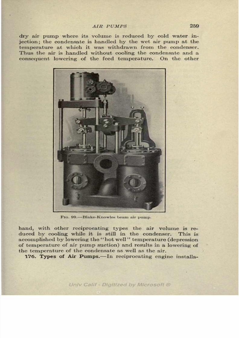
8/3/2019 Marine Power Plant Chaprich
http://slidepdf.com/reader/full/marine-power-plant-chaprich 271/335
AIR PUMPS 259
dry air pump where its volume is reduced by cold water in-
jection;the condensate is handled
bythe wet air
pumpat the
temperature at which it was withdrawn from the condenser.
Thus the air is handled without cooling the condensate and a
consequent lowering of the feed temperature. On the other
FIG. 99. Blake-Knowles beam air pump.
hand, with other reciprocating types the air volume is re-
duced by cooling while it is still in the condenser. This is
accomplished by lowering the "hot well" temperature (depression
of temperature of air pump suction) and results in a lowering of
the temperature of the condensate as well as the air.
176. Types of Air Pumps. In reciprocating engine installa-

8/3/2019 Marine Power Plant Chaprich
http://slidepdf.com/reader/full/marine-power-plant-chaprich 272/335
260 THE MARINE POWER PLANT
tions a single wet air pump is used for handling both the con-
densate and air. This is almost universally driven by a rocker
arm from the main engine, Fig. 90. For an engine working at
a low vacuum this arrangement has given satisfaction although
for moderately high vacua of 26 to 27 inches an independently
operated pump would no doubt show better efficiency. Figure 99
shows a twin air pump manufactured by the Worthington Pump& Mach. Corp. which is used to a large extent for vacua up
to about 28 inches. It is very similar to the Weir pump already
mentioned except it does not
have the cooling attachment
and other special features of
the dry air pump. Other
ejector air pumps are on the
market that use water instead
of steam as the ejecting
medium; rotary air pumps are
also used to some extent.
The condenser and air pumpshould be designed so that the
condensed steam does not re-
main in the bottom of the
condenser for any appreciable
time. If water is allowed to
collect in the condenser in
contact with the tubes it
would be in contact with the
coldest cooling water (55) and
FIG. 100. hence the condensate would
be drawn off at a tempera-
ture far below that corresponding to the vacuum.
D. B. Morrison has devised a very ingenious condenser using
this principle.1 His contra-flow condenser,
Fig.100, has a
receiver in the base divided off from the rest of the condenser.
This receiver is always filled with water which soon reaches the
lowest temperature of the cooling water. A two way cock is
fitted to the lower part of the condenser so that the condensate
can be withdrawn directly from the condenser without passing
throngh this receiver, or it can be made to pass through the
1 North-East Coast Inst. of Engineers and Shipbuilders, 1910.

8/3/2019 Marine Power Plant Chaprich
http://slidepdf.com/reader/full/marine-power-plant-chaprich 273/335
AIR PUMPS 261
receiver on its way to the air pump. Thus the temperature of
the water and air going to the air pump can be controlled by this
valve. In the tropics or elsewhere when there is a fall in vacuum
due to an increase in the temperature of the circulating water, he
claims that the vacuum can be increased \% to 3 in. by use
of this device.
With a condenser similar to that described in Art. 169, the
air is cooled in the condenser without lowering the temperature
of the condensate. This condenser, therefore, accomplishes
practically the same effect of cooling the air as is done by thecold water injection in the dry air cylinder of the Weir air pump.
The wet air pump suction should always lead from the bottom
of the condenser and the air pump located well below the con-
denser so that there will be a pressure head on the pump suction
sufficient to lift the foot valves. If an attempt is made to with-
draw the air and water vapor at a temperature too close to that
corresponding to the vacuum there will be danger of the pump
becoming vapor bound.With high vacuum, the difference between the temperature
corresponding to the vacuum and that of the sea water used for
cooling water is small. For a 29-in. vacuum this temperature
difference is about 20 in the North Atlantic and in southern
waters the difference will be smaller and may even disappear.
(See Art. 197 for an illustrative example.) A large depression of
the air pump suction cannot, therefore, be counted on and the
air will often be withdrawn at a fairly large volume and then
reduced by cooling or compression in the air pump.

8/3/2019 Marine Power Plant Chaprich
http://slidepdf.com/reader/full/marine-power-plant-chaprich 274/335
CHAPTER XVII
FEED WATER HEATERS
177. General. Feed water heaters are used on practically all
merchant and naval vessels today for raising the temperature of
the feed water above that of the feed tank. Feed heating not
only increases the overall efficiency of the plant but it also
increases the evaporation in the boilers. By relieving the
boiler of the strains and unequal expansions set up by water at
low temperature, feed heating increases the life of the boiler and
reduces the maintenance charges. If the feed water was injected
into the boiler at the same temperature at which it left the
condenser, the large difference in temperature between the water
in the boiler and the entering feed would set up severe local
strains and disturb the circulation and evaporation in the
boiler. For a ship using steam at 250 Ibs. pressure and a vacuum
of 28^2 in., the water in the boiler would be at 406F. while
the condensate entering the feed tank would be in the neighbor-
hood of 80 a difference of 326F.
The exhaust steam from the auxiliaries is used almost uni-
versallyfor
heatingthe feed
water, althougha few old
shipsare
fitted with feed water heaters using live steam. Obviously, there
is a loss instead of gain in economy if live steam is used because
of the boiler losses in generating the heating steam, although
the strains on the boiler due to cold feed water are relieved.
By using the heat in the exhaust steam from the auxiliaries
there is a direct gain, as heat which would otherwise be thrown
away is recovered. Auxiliary machinery on shipboard is always
run non-condensing. Non-condensing auxiliaries are cheaper
and require less attention than those operating with a vacuum.
For the installation mentioned above operating between 250
Ibs. and 28J/2 in., the saving due to heating the feed water to 220F.
140is 140 b.t.u. per pound, or-ry^r
=12.1 per cent. Not only are
140 b.t.u. per pound or 12.1 per cent of the heat saved, but this
262

8/3/2019 Marine Power Plant Chaprich
http://slidepdf.com/reader/full/marine-power-plant-chaprich 275/335
FEED WATER HEATERS 263
heat does not have to be added in the boiler as heat of the
liquid, and the capacity of the boiler is increased.
178. Open and Closed Heaters. There are two types of feed
water heaters used in power plant work open and closed. In
open heaters the feed water and the heating steam mix; in the
closed or tubular heater the heating steam and feed water do
not mix; the water passes through tubes and the heating steam
enters the space within the shell and surrounds the tubes on the
outside. Figure 101 shows a type of.open heater, and Figs. 102
and 103 showtypes
of closed
heaters. Both open and
closed heaters accomplish
the same results in raising
the temperature of the feed
water. The closed heater
acts the same as a surface
condenser working without
a vacuum. Thefeed
waterpassing through the tubes
condenses the steam and
absorbs the heat of vapori-
zation (z2r2) ;the heat of the
liquid (q2)is carried away
by the drip from the feed
water heater to the feed
water tank and is absorbed
FIG. 101. Bethlehem-Weir open feed
water heater.
by the feed water when the
drip mixes with the conden-
sate from the main engines
in the feed tank. The open heater acts as a jet condenser.
The steam and feed water mix together and the heat of vapor-
ization (rc2r2) and the heat of the liquid (qz) in the entering
steam are given up directly to the water when the two mix on
entering the heater. The heat of the liquid (q2) mentionedabove is the heat above that in the air pump discharge.
Open heaters are cheaper, simpler to maintain, and free the
air from the feed water better than closed heaters. The tempera-
ture of the feed can be raised slightly higher for a given pressure
of heating steam than with closed heaters. On the other hand,
closed heaters occupy more space than open heaters and as

8/3/2019 Marine Power Plant Chaprich
http://slidepdf.com/reader/full/marine-power-plant-chaprich 276/335
264 THE MARINE POWER PLANT
they are always located on the suction side of the feed pump, the
temperature of the feed water is limited to about 180 unless
the heater is given an elevation well above the feed pump.Water at 180F. is about the hottest that can be handled by a
feed pump unless there is a positive head on the suction side of
the pump. An additional "hot well" pump is required with
FIG. 102. Reilly feed water heater.
openheaters to
pumpthe feed water from the feed and filter
tank to the heater.
Open heaters are employed in stationary plants more than
closed heaters because of their cheapness and because of the
more complete separation of the air from the feed water possible
with the open heater. They have not been used to any extent
on shipboard chiefly because of the large amount of lubricating
oil generally found in the auxiliary exhaust. Because of the

8/3/2019 Marine Power Plant Chaprich
http://slidepdf.com/reader/full/marine-power-plant-chaprich 277/335
FEED WATER HEATERS 265
more general use of turbine and electric driven auxiliaries and
the consequent freedom of oil in the auxiliary exhaust
steam,open heaters are being advocated today to some extent for use
on shipboard.
Closed heaters may be located either on the suction side
(low pressure heaters) or discharge side (high pressure heaters)
of the feed pump. The general practice,
however, is to fit them on the discharge
side of the pump as there is then no diffi-
culty with vapor forming in the
pumpcyl-
inder due to the high temperature of the
pump suction. Heaters located on the dis-
charge side of the feed pump must be built
to withstand full boiler pressure and conse-
quently are heavier, more expensive and
more difficult to keep tight than low pressure
heaters.
179. Closed Heater Installation.
Figure104a shows an installation of a Reilly two
pass closed feed water heater. The auxiliary
exhaust line is connected to the shell of
the heater, and also through an automatic
back pressure valve to the auxiliary con-
denser. If the supply of exhaust steam is
greater than needed for feed heating the
back pressurevalve will
open and dischargesteam to the auxiliary condenser as soon as
the pressure builds up in the exhaust line.
The condensate from the exhaust steam is
drained from the shell of the feed heater to
the filter end of the feed and filter tank,
so that the heat of the liquid above the
temperature of the air pump suction is
recovered. The drain to the feed and filter
tank is either direct or through a trap. In the former case a
small amount of water is kept in the bottom of the heater as
a water seal. A gage glass is fitted to the bottom of the heater
so that the water level can be observed and the correct level is
maintained by regulating a valve in the drain line. Air vents
are fitted in the bottom of the heater just above the water
FIG. 103. Schutte &Koerting feed water
heater.
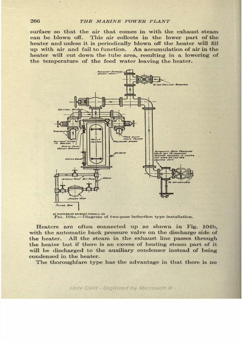
8/3/2019 Marine Power Plant Chaprich
http://slidepdf.com/reader/full/marine-power-plant-chaprich 278/335
266 THE MARINE POWER PLANT
surface so that the air that comes in with the exhaust steam
can be blown off. This air collects in the lower part of the
heater and unless it is periodically blown off the heater will fill
up with air and fail to function. An accumulation of air in the
heater will cut down the tube area, resulting in a lowering of
the temperature of the feed water leaving the heater.
3B LOH f/ffjxjff KeceittK
BY PERMISSION GRISCOM-RUSSELU CO.
FIG. 104a. Diagram of two-pass induction type installation.
Heaters are often connected up as shown in Fig. 104b,
with the automatic back pressure valve on the discharge side of
the heater. All the steam in the exhaust line passes through
the heater but if there is an excess of heating steam part of it
will be discharged to the auxiliary condenser instead of being
condensed in the heater.
The thoroughfare type has the advantage in that there is no

8/3/2019 Marine Power Plant Chaprich
http://slidepdf.com/reader/full/marine-power-plant-chaprich 279/335
FEED WATER HEATERS 267
tendency for the feed heater to become air bound as might be
the case with the induction type if the air vent was not given
proper attention.
180. Types of Closed Feed Heaters. Figure 102 shows a Reilly
marine type two pass heater. This make of heater is built in
both single and double pass. The single pass is lighter and
somewhat simpler; the double pass, however, has a higher
TO Got/offtse*
fl<.Tflt. Sox
faner
BY PERMISSION GRISCOM-RUSSELL CO,
FIG. 104b. Diagram of two-pass thoroughfare type installation.
efficiency as the length of the water travel in the steam space is
twice as great as in the single pass type. The heating surface
of the Reilly heater consists of helical coils fastened to the top
and bottom headers by screwed union joints. The helical shape
of the tubes causes the water in its passage through them to be
constantly thrown to the outside by centrifugal force. The
tubing is also crimped, which further assists to agitate the water
8/3/2019 Marine Power Plant Chaprich
http://slidepdf.com/reader/full/marine-power-plant-chaprich 280/335
268 THE MARINE POWER PLANT
in its passage along the tube. Because of the high efficiency of
the tubes in heating 'the water, a much smaller heating surface
is required than when straight tubes are used. The Reilly heater
has no baffles in the steam space, which are required in all
straight tube heaters. This heater is built with a cast iron shell
which insures a long life to the heater.
Figure 103 shows a Schutte & Koerting four pass feed
water heater. The feed water enters at the top, makes
four passes through the tubes as shown in Fig. 103 and leaves
at the top. The shell is of cast iron and the tubes are % in.
seamless drawn of brass or copper. The exhaust steam enters
the shell near the top and drains off at the bottom. The con-
struction, as clearly shown in Fig. 103, allows the heater to be
readily taken apart for inspection or replacing a tube.
181. Series Heaters. The temperature of the feed water
leaving the feed heater can never be greater than the tempera-
ture corresponding to the pressure of the exhaust steam and
generally the feed temperature is 5 to 12 lower than the auxiliary
exhaust. With auxiliary exhaust at 5 Ibs. gage (228F.) the
feed temperature is around 220F. It often happens that there
is more auxiliary exhaust steam than can be used for feed
heating (see example in Art. 205) and under such conditions
this heat is frequently rejected to the auxiliary condenser as
a dead loss.
In order to increase the feed temperature, series heaters are
sometimes used. Secondary heaters are placed between the
rnain heater and the boiler or series coils are placed in the
discharge end of the main feed heater. These receive the
discharge from the direct acting pumps or the drips from the
oil heater, evaporator, etc., which are at a higher temperature
than the auxiliary exhaust. While this will increase the tempera-
ture of the feed waterand the efficiency of the plant the increased
complicationscaused
bythe additional
pipingand
separateexhaust lines seldom warrant the adoption of series heaters.
182. Economizers. An economizer is a feed water heater
located in the path of the hot gases between the boiler and the
stack. They are widely used in land installation and show a
good gain in economy by transferring the heat of the waste
gases to the feed water. When used on shore mechanical draft
is always required as economizers not only create an added

8/3/2019 Marine Power Plant Chaprich
http://slidepdf.com/reader/full/marine-power-plant-chaprich 281/335
FEED WATER HEATERS 269
resistance but reduce the stack temperature to such a low
figurethat natural draft is
impossible.The Howden draft system as used with Scotch boilers is
similar in principle; but here the heat in the waste gases is
used to heat the air used for combustion instead of the feed
water.
In land installations where economizers are used a large
supply of auxiliary exhaust steam is not available for feed
heating as on shipboard. As shown in the calculations for feed
heater (Art. 205),there is
generallysufficient exhaust steam on
shipboard to raise the feed water up to a temperature of 220F.
Therefore, if economizers are used on shipboard they must
raise the feed water from around 220F. to as high a temperature
as possible with the waste gases.
The feed water is pumped through the economizer under full
boiler pressure; the water enters the economizer at the upper part
so that the coldest water is in contact with the coolest gases and
the flow of the feed water is thus opposite to that of the gases.An example will show the possibilities of the economizer:
Boiler heating surface = 5,240 sq. ft.
Actual evaporation per hour = 33,000 Ibs.
Oil per hour = 2,630 Ibs.
Temperature of feed entering economizer ti= 220F.
Assumed temperature of feed leaving economizer
Temperature of gases leaving boiler < 3= 550F.
Assumed temperature of gases leaving economizer <
Mean temperature difference between gases and water lm .
Stack gases with 24 per cent excess air = (14 XI.24) +1.0 = 18.3 Ibs.
per Ib. oil.
Specific heat of gases= .238.
B.t.u. available in waste gases= 18.3X 2630 X.238X230 =
2,640,000
per hour.
B.t.u. required to raise feed water (80) =33,000X80=2,640,000 per
hour.
The conditions have been assumed so as to give a balance be-
tween heat available in the gases and heat required to raise
the feed water. Thus under the assumed conditions we can
expect a rise of 80 in the feed water for a drop of 230 in the
temperature of the waste gases.

8/3/2019 Marine Power Plant Chaprich
http://slidepdf.com/reader/full/marine-power-plant-chaprich 282/335
270 THE MARINE POWER PLANT
The coefficient of heat transfer between gases and water is
about 4.5 b.t.u. per sq. ft. per degree difference per hour. B.t.u.
heat transfer per sq. ft. per hour = 4.5 XI64 = 740 b.t.u.
2 640 000Economizer heating surface required
= '
=3,600 sq. ft.
As the heating surface of the boiler is 5,240 sq. ft., we see that the
economizer surface necessary to increase the feed temperature
80 is nearly 70 per cent of that required for generating steam in
the boilers. It is evident, as shown by the above example, that
both space and weight requirements prohibit the use of econ-
omizers on shipboard unless used in the place of the auxiliary
exhaust method of heating the feed water.
If auxiliaries with low steam consumption are used, as would
be the case with electric driven auxiliaries supplied with current
from a turbine driven generator, economizers are entirely
feasible. With such an installation the steam consumption of
the auxiliaries would be about one-half what it is at present andthe temperature of the feed water leaving the heater would be
around 140F. Under these conditions the economizer would
operate with a greater mean temperature difference and its
heating surface would be smaller.
There is no doubt that attention to economy will next be
focused on the auxiliaries. It is certainly poor engineering to
heat the feed water with steam when a large supply of heat is
available in the uptake gases. A single generating set working
under high pressure and at the same vacuum as the main turbine
and supplying current to electrically driven auxiliaries is an
obvious step in marine engineering.

8/3/2019 Marine Power Plant Chaprich
http://slidepdf.com/reader/full/marine-power-plant-chaprich 283/335
CHAPTER XVIII
THE POWER PLANT LAYOUT
183. Power Plant Diagram. A diagrammatic layout of the
marine power plant is shown in Fig. 105. The live steam line,
exhaust steam lines and feed lines are clearly shown by different
types of lines. In order not to make the diagram too compli-
cated several smaller pieces of apparatus, as the forced draft
blower and auxiliary circulating pump, have been omitted and
the evaporator and distiller auxiliaries have also been left out.
The diagram should receive careful attention during the study
of marine engineering and especially in connection with the
power plant calculations in Chap. XIX.
Power Plant Layouts. Typical engine and boiler room layouts
are shown in Figs. 106 to 112. Figures 106a and 106b show
a plan and elevation of the machinery of the electric driven
cargo ship"Eclipse," one of the first merchant ships to be
fitted with this type of machinery. Figure 107 shows the electric
drive layout for the quadruple screw battleship "New Mexico."
The machinery arrangement for the battle cruiser "Hood" is
shown in Fig. 111. This installation consists of four single
reduction gear units of 36,000 s.h.p., the data for which are given
in Table X. Figure 108 shows the echelon arrangement of the
geared turbine machinery of the destroyer "Wadsworth" and
Fig. 112 the arrangement of a ship with geared electric drive
(Table X) . Figures 109 and 1 10 are included as a representative
layout of a single screw geared turbine ship.
Layouts of merchant ship machinery with reciprocating
engines, geared turbines, etc., have not been included as the
reader can find such layouts in current issues of marine engine-
ering publications.
The above layouts need no explanation. They are included
here to show some of the special types of machinery used for
ship propulsion.
271

8/3/2019 Marine Power Plant Chaprich
http://slidepdf.com/reader/full/marine-power-plant-chaprich 284/335
272 THE MARINE POWER PLANT
_J

8/3/2019 Marine Power Plant Chaprich
http://slidepdf.com/reader/full/marine-power-plant-chaprich 285/335
POWER PLANT LAYOUT 273
2& 29
BY PERMISSION "MARINE ENGINEERING"
FIQ. 106a. Plan of engine room of the "Eclipse.1

8/3/2019 Marine Power Plant Chaprich
http://slidepdf.com/reader/full/marine-power-plant-chaprich 286/335
274 THE MARINE POWER PLANT
BY PERMISSION "MARINE ENGINEERING-
FIG. 106b. Elevation of engine room of the "Eclipse.1

8/3/2019 Marine Power Plant Chaprich
http://slidepdf.com/reader/full/marine-power-plant-chaprich 287/335
POWER PLANT LAYOUT
Fire andBilge
FeedPressure Fire andBilge Pumps
Pumps -^ __ Pump
275
FIG. 107. Machinery arrangement of U. S. S. "New Mexico."
FIG. 108. Machinery arrangement U. S. S. "Wadsworth.'

8/3/2019 Marine Power Plant Chaprich
http://slidepdf.com/reader/full/marine-power-plant-chaprich 288/335
276 THE MARINE POWER PLANT
OutboardDischarge
Cashing MainFeedAux.ree.dR/mp
StaChesf Pumps DischgyeManifold
> . f 1TO, J a
Fio. 109. Plan of engine room of geared turbine ship.

8/3/2019 Marine Power Plant Chaprich
http://slidepdf.com/reader/full/marine-power-plant-chaprich 289/335
POWER PLANT LAYOUT 277
/LubnccrtingOi
Basel/tie BilgeSudionManifold
FIG. 110. Section through engine room shown in figure 109.
48'
Toial3ha'ftHorsepower- 144,000
Revs.ofPropellerShaffs- 2/0
72* Revs.ofH.PJurbines 1,497
Revs.ofLP. Turbines 1,096
FROM TRANS. INST. NAV. ARCH, 1919
FIG. 111. Plan of geared turbine installation H. M. S. "Hood."
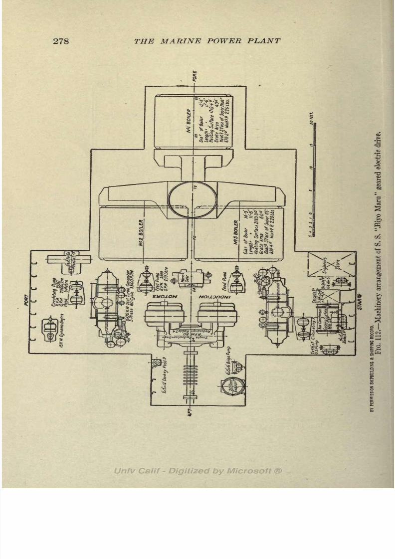
8/3/2019 Marine Power Plant Chaprich
http://slidepdf.com/reader/full/marine-power-plant-chaprich 290/335
278 THE MARINE POWER PLANT
S

8/3/2019 Marine Power Plant Chaprich
http://slidepdf.com/reader/full/marine-power-plant-chaprich 291/335
CHAPTER XIX
COMPUTATIONS FOR THE POWER PLANT OF THEMERCHANT SHIP
Case I. Geared turbines with both coal and oil fired water-
tube boilers.
E.H.P. = 1,500.
Service s.h.p.=2,700 (single screw).
Service speed= 11 knots.
Propeller r.p.m.=90.
(See Journal A. S. N. E., May, 1920, for propeller calculations.)
Double reduction gears with reduction of 36 : 1.
Steam pressure at throttle = 260 Ibs. gage.
Boiler pressure= 270 Ibs. gage.
Superheat =100F.Vacuum in condenser 29 in. (30 in. barometer).
Back pressure at turbine exhaust nozzle = 28.8 in.
High initial steam pressure with a reasonably high superheat
and a high vacuum has been adopted in order to reduce the
steam consumption as low as possible. A high vacuum requires
close attention to air leakage, but with a reasonably tight system,
proper air pump equipment and an efficient engine force, 29in. would be possible except in tropical waters. There is no
doubt that 29 in. is rather too high to expect in service con-
ditions on the average cargo steamer. It has been selected more
to illustrate the possibilities and value of high vacuum than to
follow present day practice.
A steam pressure as high as 270 Ibs. is beyond the practice
of Scotch boilers, but good practice with water-tube boilers. In
Case II, where Scotch boilers are used, a lower initial pressure
will be used.
184. Steam Consumption of Main Turbine. The main
engines should be considered first so that a steam consumption
can be settled on for estimating the size of boilers and auxiliaries.
Needless to say, a fairly accurate estimate of the steam con-
279
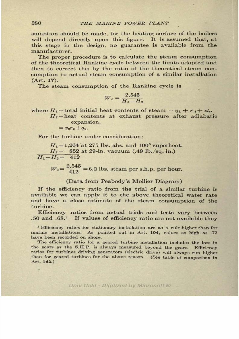
8/3/2019 Marine Power Plant Chaprich
http://slidepdf.com/reader/full/marine-power-plant-chaprich 292/335
280 THE MARINE POWER PLANT
sumption should be made, for the heating surface of the boilers
will depend directly upon this figure. It is assumed that, at
this stage in the design, no guarantee is available from the
manufacturer.
The proper procedure is to calculate the steam consumption
of the theoretical Rankine cycle between the limits adopted and
then to correct this by the ratio of the theoretical steam con-
sumption to actual steam consumption of a similar installation
(Art. 17).
The steamconsumption
of the Rankine cycle is
2,545
where HI = total initial heat contents of steam <?i + r i-f cta .
H2= heat contents at exhaust pressure after adiabatic
expansion.
For the turbine under consideration :
#! = 1,264 at 275 Ibs. abs. and 100 superheat.
Hi = 852 at 29-in. vacuum (.49 Ib./sq. in.)
#,_#,= 412
-TTQ" =6.2 Ibs. steam per s.h.p. per hour.
(Data from Peabody's Mollier Diagram)
If the efficiency ratio from the trial of a similar turbine is
available we can apply it to the above theoretical water rate
and have a close estimate of the steam consumption of the
turbine.
Efficiency ratios from actual trials and tests vary between
.50 and .68.1
If values of efficiency ratio are not available they
1
Efficiency ratios for stationary installation are as a rule higher than for
marine installations. As pointed out in Art. 104, values as high as .73
have been recorded on shore.
The efficiency ratio for a geared turbine installation includes the loss in
the gears as the S.H.P. is always measured beyond the gears. Efficiency
ratios for turbines driving generators (electric drive) will always run higherthan for geared turbines for the above reason. (See table of comparison in
Art. 162.)

8/3/2019 Marine Power Plant Chaprich
http://slidepdf.com/reader/full/marine-power-plant-chaprich 293/335
COMPUTATION FOR POWER PLANT 281
may be worked up from trial data as shown in the following
examples :
Published data of a trial of a similar turbine of 4,000 s.h.p.
showed a steam consumption on trial of 11.2 Ibs. per s.h.p. per
hour with an initial steam pressure of PI = 191 Ibs. abs. dry
steam and a vacuum of 28.75 Ibs. (P2= .61 Ibs./sq.in.)
The calculations for the theoretical steam consumption of
this turbine are as follows :
//i= 1,197 at 191 Ibs. abs. No superheat
#2 = 840
#!-#*= 357
7 14Ratio of theoretical to actual (efficiency ratio)
=jYo^fr*.
As a further illustration of the use of efficiency ratio the following
comparison is given. In Marine Engineering, for May, 1919, a
proposal for an electric drive1 was given. The estimated steam
consumption of the turbine was quoted as 9.4 Ibs. with PI =
280 Ibs. abs. and 150 superheat and P2= 28.5 in.
Hi = 1,292 at 280 Ibs. abs. 150 superheat.
#2= 887 at .75 Ibs./sq.in. abs.
#!-#2= 405
TO p, 2,545 2,545= =
9.4X405=
'67
By estimating the steam consumption by the procedure
outlined above all guesswork is eliminated and a proper allow-
ance can be made for changes of superheat, increase or decrease
of initial steam pressure, and variations in vacuum. The
theoretical result of course is of little value unless coefficients
are available from practice.
Returning again to the problem in hand and using an effi-
ciency ratio of .62 we have:
r> c\
Actual steam consumption (Wa)=-^
Ibs. = 10.0 Ibs. s.h.p./hour.
!See footnote on page 280.

8/3/2019 Marine Power Plant Chaprich
http://slidepdf.com/reader/full/marine-power-plant-chaprich 294/335
282 THE MARINE POWER PLANT
This of course is an estimated figure and may have to be
modified later to agree with the manufacturer's guarantee.
Obviously for continuous service at sea, where the conditions are
not those that exist on trials and where air leakage may reduce
the vacuum, a steam consumption as low as obtained on trial
cannot be expected. The efficiency of .62 used above is very
conservative for trial conditions and later a percentage allowance
will be used to cover all possible increases in steam and fuel
consumption in service.
185. Total SteamConsumption.
In order to determine the
size of the boilers and other auxiliaries an estimate must be
made at this stage of the steam used by the auxiliaries.
The present practice is to quote auxiliary steam consumption
as a percentage of the main engines. This is not a good method,
especially for an installation like the one under consideration.
The steam consumption of many of the auxiliaries is a constant
quantity and but few show a reduction in steam consumption
with a reduction in main engine steam; in fact some, such asthe circulating and air pump, will increase with a high vacuum
of 29 in. Consequently, with a geared turbine of low steam
consumption and high vacuum we would expect a higher per-
centage than with a reciprocating engine. A much better wayto quote auxiliary consumption is in pounds per s.h.p. of the
main engines.
As will be shown later no effort is going to be made in this
installation to use auxiliaries of high efficiency, and a rather
high figure should be used for auxiliary steam. A reasonable
value for this, from data at hand, is about 20 per cent of that
used by the main engines or 2.0 per s.h.p. of main engines per
hour.
We now have for the estimated total steam consumption:
Main engines: 2,700X 10 = 27,000 Ibs.
Auxiliaries: 27,000 X.20= 5,400 Ibs.
Total steam =32,400 Ibs. per hour.
Later a separate calculation will be made for the steam used byeach piece of auxiliary machinery and a more accurate value
obtained for auxiliary steam consumption.
With the above estimate of steam consumption we are now

8/3/2019 Marine Power Plant Chaprich
http://slidepdf.com/reader/full/marine-power-plant-chaprich 295/335
COMPUTATION FOR POWER PLANT 283
ready to calculate the size of boilers required. Water-tube
boilers will be used in this case and, to fully illustrate the problem,calculations will be carried through for both coal fired and oil
fired boilers.
Lbs.
Steam used for propelling machinery and ship
auxiliaries................................. 32,400
Arbitrary allowance for heating ............... 600
Total steam to be generated per hour ........ 33,000
33 000Steam per s.h.p. per hour all purposes
= * = 12.2 Ibs.
186. Boilers. (a) Babcock & Wilcox coal fired water-tube
boilers. Experience with hand fired boilers in the merchant
service indicates 20 to 25 Ibs. of coal per sq. ft. of grate is about
the maximum that can be attained for continuous service with-
out undue difficulty in stoking. Probably 22 Ibs. of "dry coal"per sq.ft. g.s. is as high a figure as should be used for design
purposes. Higher values of this can be maintained for short
times; 30 and even 45 Ibs. per sq.ft. G.S. per hour have been used
on naval vessels but not for continuous service, however.
It will be observed that the above rate is for "dry coal'1
with a reasonable percentage of ash. If the coal contains 5
per cent moisture the rate will be 23 Ibs. per sq. ft.;and if the
coal is high in ash an even higher rate will have to be maintainedto give the required evaporation.
It is not a wise plan to cut too close on boiler heating surface
or allow too high a rate of combustion, for a ship that requires
hard firing to maintain the required steam pressure soon gets
a bad reputation and it is more difficult to pick up firemen.
The factor of evaporation for a boiler producing steam at
285 Ibs. abs. and 100 superheat and feed at 218F. (10 below
auxiliary back pressure of 5 Ibs. gage) is as follows:
Factor of Evaporation = 1>2
g
5
7J"4
186 = 1-H
The size of the boiler is obtained by the following procedure :
Assume heat contents of coal = 14,000 b.t.u. per Ib.
Assume a boiler efficiency in service = 66 per cent.

8/3/2019 Marine Power Plant Chaprich
http://slidepdf.com/reader/full/marine-power-plant-chaprich 296/335

8/3/2019 Marine Power Plant Chaprich
http://slidepdf.com/reader/full/marine-power-plant-chaprich 297/335
COMPUTATION FOR POWER PLANT 285
ciency and heat contents of the coal would not warrant the
above refinement in calculations at this
stage. However,the
actual condition should be kept in mind, for in certain cases it
might be of importance.
The rate of evaporation calculated above can be compared with
the curve shown in Fjg. 113, as a check. The curve for the
B. & W. boiler in Fig. 113 shows that for a rate of combustion
of 22 Ibs. of dry coal per sq. ft. G.S. per hour the equivalent
evaporation per sq. ft. of heating surface is 5.6 Ibs. In this
particularcase the ratio of
H.S./G.S.was chosen so that it
gavean exact check with the curve. This, however, will not always
happen.
24- 26 28 30 32 34 36 3
Pounds Dry Coal per Sq. Ft,G.S,per Hour
FIG. 113.
The curves in Fig. 113 have been compiled from a large
number of tests and will serve as a guide for fixing the heating
surface of coal fired boilers. They should be used with care
and discretion, however, for the evaporation per sq. ft. of H.S.
will vary not only with changes in the ratio of H.S./G.S. but also
with the efficiency of the boiler.1 The fact that the Scotch
boiler curve lies above some of the other curves is simply due
to the general practice of building Scotch boilers with a lower
ratio of H.S./G.S. and does not indicate a higher efficiency.
In order to allow a good margin for an increase in steam
1 The actual evaporation per sq. ft. of H.S. per hour can be expressed
as follows:
Eff. X rate of combustion X b.t.u. per Ib. coalActual Evap.=
(H.& + G.8.) X <H,-
4.)

8/3/2019 Marine Power Plant Chaprich
http://slidepdf.com/reader/full/marine-power-plant-chaprich 298/335
286 THE MARINE POWER PLANT
consumption of main engines and auxiliaries in service over
that of trial conditions, and to allow for poor coal, bad firing
and a general falling off in boiler efficiency this calculated heat-
ing surface should be increased by about 15 per cent. This is
the only increase so far allowed, for the assumed steam con-
sumption was based on a trial result and the heating surface
was based on good service practice. It is far better to hold
closely to the calculated figures and allow an overall increase
in one place to take care of all contingencies, than to keep adding
small increases to each calculation.
Heating surface to be provided= 6,550X1. 15
=7,540 sq. ft.
For the boilers with 15 per cent increase in heating surface:
H.S. = 7,540 sq.ft.
G.S.= 201 sq.ft.
Evaporation per pound of coal (actual)
360'
Evaporation per pound of coal (equivalent)
= 8.55 X 1.11 = 9.5 Ibs.
As a check on the calculated equivalent evaporation we have :
- - = 9.5 Ibs. of water from and at 212 per Ib. coal.
y i u.4
From Sterling's ''Marine Engineers' Handbook/' page 733, the
following B. & W. boilers have been tentatively selected. A
final selection can only be made by making a study of the
arrangement and layout on the plans of the ship.
Three Boilers (4-in. tubes)
Grate surface = 66.8 sq.ft. each (3 boilers = 200 sq.ft.)
Heating surface = 2,490 sq. ft. each (3 boilers = 7,460 sq. ft.)
H.S.Ratio ^-^ =37.28.
(jr.b.
Length of tube 10 ft.
Weight, dry = 78,000 Ibs. each (excluding superheater).
Weight, wet = 93,000 Ibs. each (excluding superheater)-
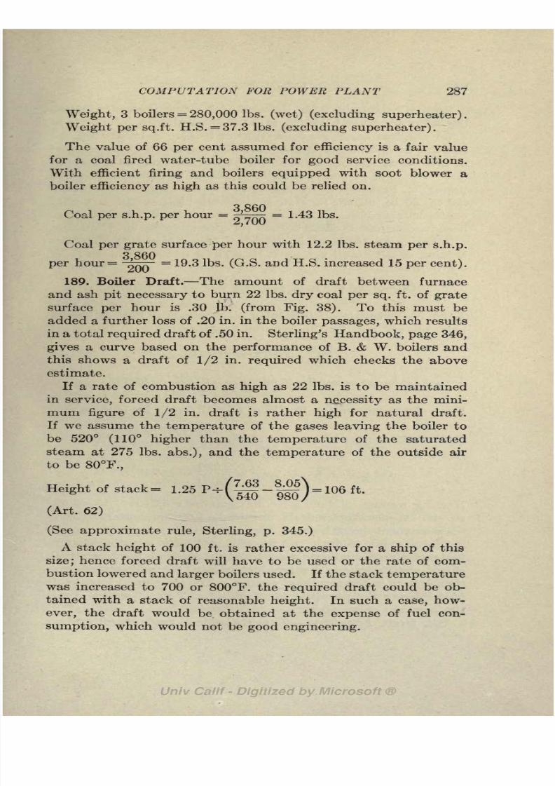
8/3/2019 Marine Power Plant Chaprich
http://slidepdf.com/reader/full/marine-power-plant-chaprich 299/335
COMPUTATION FOR POWER PLANT 287
Weight, 3 boilers = 280,000 Ibs. (wet) (excluding superheater).
Weight per sq.ft.H.S. = 37.3 Ibs.
(excluding superheater).
The value of 66 per cent assumed for efficiency is a fair value
for a coal fired water-tube boiler for good service conditions.
With efficient firing and boilers equipped with soot blower a
boiler efficiency as high as this could be relied on.
Coal per s.h.p. per hour = ^^ = 1.43 Ibs.
Zj 1 00
Coal per grate surface per hour with 12.2 Ibs. steam per s.h.p.Q OCA
per hour ='
~ = 19.3 Ibs. (G.S. and H.S. increased 15 per cent).
189. Boiler Draft. The amount of draft between furnace
and ash pit necessary to burn 22 Ibs. dry coal per sq. ft. of grate
surface per hour is .30 Ib. (from Fig. 38). To this must be
added a further loss of .20 in. in the boiler passages, which results
in a total
requireddraft of .50 in.
Sterling's Handbook, page 346,gives a curve based on the performance of B. & W. boilers and
this shows a draft of 1/2 in. required which checks the above
estimate.
If a rate of combustion as high as 22 Ibs. is to be maintained
in service, forced draft becomes almost a necessity as the mini-
mum figure of 1/2 in. draft is rather high for natural draft.
If we assume the temperature of the gases leaving the boiler to
be 520 (110 higher than the temperature of the saturatedsteam at 275 Ibs. abs.), and the temperature of the outside air
to be 80F.,
Height of stack= 1.25P-- = 106 ft.
(Art. 62)
(See approximate rule, Sterling, p. 345.)
A stack height of 100 ft. is rather excessive for a ship of this
size; hence forced draft will have to be used or the rate of com-
bustion lowered and larger boilers used. If the stack temperature
was increased to 700 or 800F. the required draft could be ob-
tained with a stack of reasonable height. In such a case, how-
ever, the draft would be obtained at the expense of fuel con-
sumption, which would not be good engineering.

8/3/2019 Marine Power Plant Chaprich
http://slidepdf.com/reader/full/marine-power-plant-chaprich 300/335
288 THE MARINE POWER PLANT
Sample calculations for the size and horsepower of a forced
draft fan are given under Case (6) following:
(b) Oil fired water-tube boiler (Foster type). A boiler using oil
fuel can be operated at higher rate of combustion than with coal
as there is no arduous work on the part of the firemen to account
for. The rate of combustion is expressed in Ibs. of oil burned
per sq. ft. heating surface per hour. For a cargo ship a rate of
.50 to .60 Ib. oil/sq. ft. H.S. is probably high enough to use for
continuous service. Rates as high as 1.0 Ib./sq. ft. H.S. have
been used onnaval vessels but not for continuousservice,
however.
Allowing an efficiency in service of 72 per cent a rate of com-
bustion of .50 Ib. oil per sq. ft. H.S., and 18,800 b.t.u. per Ib. of
oil, we have,
OU burned per hour = =2,620 Ibs.
A rate of combustion of 0.50 Ib. of oil per sq. ft. of heating surface
perhour will
givefor the
required heating surface,
?4^= 5,240 sq.ft. H.S..50
33 000Actual evaporation per Ib. of oil r- = 12.6 Ibs.
Equivalent evaporation per Ib. of oil = 12.6 XI. 11 = 14.0 Ibs.
qoEquivalent evaporation per sq. ft. H.S. = -^ - X 1 . 1 1 = 7.0.
Oil per s.h.p. per hour = ^^ = 0.97 Ib.((
Heating surface of boilers to be installed = 5,240XL 15 = 6,020
sq. ft. Approximate draft required= 1.00 in. water. (From
tests on this
typeof
boiler.)The amount of draft to use with fuel oil is a rather illusive
factor, for published data vary widely. Ships of the Navy with
closed stokeholes use a much higher rate, for military reasons,
than is used in the merchant service. The fan should be capable
of delivering the proper amount of air at 2 in. of water twice
the pressure given above.
188. Draft Apparatus. The theoretical amount of air per

8/3/2019 Marine Power Plant Chaprich
http://slidepdf.com/reader/full/marine-power-plant-chaprich 301/335
COMPUTATION FOR POWER PLANT 289
pound of fuel oil is about 14 Ibs. (184 cu. ft.) for the average run
of fuel oil. Allowing 30 per cent excess air, the air required
per hour is:
Air per hour = 2,620X14 XI.30 = 47,500 Ibs.
Blower capacity in service =
47,500
60X.07610,400 cu. ft. per min. at 60F.
Air pressure allowed = 1.0 in. of water (68 ft. air)
Service hp. of blower at 40 per cent efficiency=
47,500X68
33,000X 60X.40
The common practice in fixing the area of stack and uptakes
is to allow 1 sq. ft. of area for each 200 Ibs. oil burned per hour.
Naval vessels use smaller stacks than this, but on the other hand
the drafts used are greater.
2 620Area of stack = - - = 13.1 sq. ft.
ZOO
Case II. Scotch Boilers with Coal; Reciprocating Engines.
The following conditions are assumed for this case:
I.H.P. = 2,900
R.p.m.= 90
Pi at throttle = 200 Ibs. gage (215 Ibs. abs.)
Boiler pressure= 210 Ibs. gage (225 Ibs. abs.)
Superheat at boiler = 60F. (*i= 452F.)
Vacuum in condenser = 27 in.
Four cylinder triple expansion engine.
189. Main Engines (steam consumption). We will follow the
same procedure to find the steam consumption as was used in
Case I. From the trial data of the U.S.S.
"
Delaware" the
efficiency ratio is found to be 56 per cent. Calculations both
for the ''Delaware" and the assumed conditions follow:
U.S.S. "Delaware:"
PI = 285 Ibs. abs. (at engine)
Superheat = 61.6F. (at engine)

8/3/2019 Marine Power Plant Chaprich
http://slidepdf.com/reader/full/marine-power-plant-chaprich 302/335
290 THE MARINE POWER PLANT
Vacuum = 26.3 in. (1.82 Ibs. abs.)
Steam consumption on trial (wa)= 13.38 Ibs. per i.h.p. per hour.
2545
(w t)theoretical consumption
="040"
= 7-50 Ibs. per i.h.p.
#! = 1,245
#2= 905
!-# 2= 340
7 ^0Eff. ratio = = .56
The above data are from the full power trial; at 19 knots the
efficiency ratio was higher (see A. S. N. E., Nov., 1909). For
further data on efficiency ratios see Table IX.
Steam consumption for Case II:
P! at throttle = 215 Ibs. abs.
Superheat (at throttle)= 55
Vacuum in condenser= 27 in. (1.47 Ibs.)
Assumed efficiency ratio = 55 per cent
#! = 1,232
#2= 902
#!_#,,= 330
2545Theoretical steam consumption= = 7.70 Ibs. per i.h.p. per hour.
ooU
Probable action consumption=
^-= 14.0 Ibs. per i.h.p. per hour.
Before taking up the consideration of the boilers it is necessary
to make an estimate of the steam used by auxiliaries. Naval
vessels with engines similar to the "Delaware" show a steam con-
sumption for the main engine auxiliaries of about 12 per cent
of that of main engines. This, however, does not include
gen-erator set or hull auxiliaries. Merchant ship auxiliaries use
about 15 per cent of that used by the main engines or about
2.0 per i.h.p. per hour. Allowing 15 per cent for the installation
under consideration we have 6,100 Ibs. per hour or 2.1 Ibs. per
i.h.p. per hour. As pointed out in Case I a detailed estimate
should be made for each auxiliary later on, to check up this
preliminary estimate.

8/3/2019 Marine Power Plant Chaprich
http://slidepdf.com/reader/full/marine-power-plant-chaprich 303/335
COMPUTATION FOR POWER PLANT 291
Lbs per hour
Steam required for main engine=2,900X 14 = 40,600
Steam required for all auxiliaries (15 per cent) 6,100
46,700
Heating (arbitrary allowance) 600
Total steam required per hour (16.3 Ibs. per I.H.P.) 47,300
190. Scotch Boilers. We will assume the same rate of com-
bustion as was used in Case I with water-tube boilers, namely,
22 Ibs. dry coal per sq. ft. of grate surface per hour. This is
close to the upper limit for continuous hand firing. We will,
however, design the boiler for this rate and then, as before,
allow sufficient margin in the heating surface so that this rate
will not be exceeded in service.
The factor of evaporation for the conditions stated is
Factor of evaporation= 2 = -'
97Q4= 1.045
The feed water temperature has been assumed, 218F. as before.
This is 10 below the temperature of the auxiliary exhaust which
is used for feed heating. In calculating the factor of evapora-
tion, the initial condition has been assumed as dry steam, no
account being taken of the 60 superheat. It is planned in
this case to use a waste heat type superheater, installed in the
uptake. All the data which have been used in this estimate are
based upon Scotch boilers without superheaters, and obviously
a superheater absorbing heat from the waste gases does not
influence the boiler performance. If a flue type superheater
were used, the heat of the superheated steam would have to be
considered.
If we assume the heat contents of the coal as 14,000 b.t.u. per
Ib. and the boiler efficiency 67 per cent we have;
47,300 X (1,200-
186) , 19nlKaCoal
perhour =
14,000 X .67
=5,120 Ibs.
Grate surface = ^^ = 232 sq. ft.
&
TTg
Allowing a tentative ratio of^rW
of 36, we have:
Heating surface = 232X36 = 8,350 sq. ft.

8/3/2019 Marine Power Plant Chaprich
http://slidepdf.com/reader/full/marine-power-plant-chaprich 304/335
292 THE MARINE POWER PLANT
47 300Actual evaporation per sq. ft. H.S. = * = 5.68 Ibs. per hour.
O,OOU
Equivalent evaporation per sq. ft. H.S. = 5.68X 1.045 = 5.94 Ibs.
per hour.
Actual evaporation per Ib. of coal =
47,300 (14,000 X .67) .
1,014
Equivalent evaporation per Ib. of coal = 9.25 XI.045 = 9.70 Ibs.
In Fig. 113 is a curve showing average results from the per-
formance and trials of a large number of Scotch boilers. It will
be observed from these curves that at a rate of combustion of
22 Ibs. per sq. ft. the equivalent evaporation is 6.2 Ibs. per
sq. ft. H.S., which is slightly higher than our estimate. The
evaporation per sq.ft. H.S. for a given rate of combustion dependsTT Q
on theratio of
7s~V,so this curve
onlyserves as a
roughcheck.
Coal per I.H.P. per hour = |^ = 1.76 Ibs.
^,yuu
Allowing, as before, an increase of 15 per cent in heating sur-
face to cover all contingencies, such as poor firing, inferior coal,
dirty boilers and increased steam consumption, we have:
Heatingsurface to be
provided
=8,350
XI. 15 =9,600 sq.
ft.
Grate surface to be provided = 232X 1 . 15 = 267 sq. ft.
47 300Evaporation per sq. ft. H.S. in service = * = 4.93 Ibs. per hour
*j \J\J\J
Allowing 3 boilers of 3,200 sq. ft. we have the following
possibility (Sterling's Handbook, p. 363) :
Length,11 ft. 6 in.
Diameter, 16 ft. 6 in.
Furnaces, 4.
Tubes, 414
H.S., 3,072
G.S., 83.2

8/3/2019 Marine Power Plant Chaprich
http://slidepdf.com/reader/full/marine-power-plant-chaprich 305/335
COMPUTATION FOR POWER PLANT 293
Weight 3 boilers (wet)=640,000 Ibs.
Weight per sq. ft. h.s.=69.5 Ibs.
(Compare the above weight with that of the water-tube boilers
of Case I).
Considerable discretion based on experience must be used in
fixing the value of H.S./G.S. With a large ratio, the gases have
a better opportunity to give up their heat to the water. For
forced draft a -higher ratio should be used than with natural
draft. When waste-heat superheaters are to be used a lower value
can be used, for heat not taken up in the boiler will be absorbedby the superheater. For the same reason a boiler fitted with a
waste-heat superheater can be shorter and forced at a higher
rate than one without.
Good practice generally limits the evaporation in scotch boilers
to about 5 Ibs. per sq. ft. of heating surface per hour. Rates
higher than this are liable to cause leaks and shorten the life of
the boiler. The above service rates of 5.7 Ibs. per sq. ft. of
heating surface per hour as a maximum and 4.9 Ibs. as a minimumare certainly as high as it is advisable to go.
The results obtained in the three cases above for boiler heating
surface are given merely to illustrate a rational method of obtain-
ing the heating surface. The calculations, of course, are subject
to considerable modification, depending on the particular type of
boiler used and the exact data for this boiler that may be avail-
able from trials and experience in service.
The above clearly shows that arbitrarily basing the boiler
heating surface on the horsepower of the main engines is not a
correct or logical procedure, unless all facts regarding type of
boiler, fuel, steam consumption of engines and auxiliaries are
given proper weight.
191. Approximate Draft Required. The total draft should
be sufficient to overcome the losses through the grate, boiler
tubes, flues, superheater, and air heater. Curves showing the
necessary draft between furnace and ashpit are given in Fig. 38
Between furnace and ashpit 30 in.
Boiler tubes 40 in.
Superheater . . 20 in.
Howden heater 30 in.
Total draft between ashpit and uptake 1. 20 in.
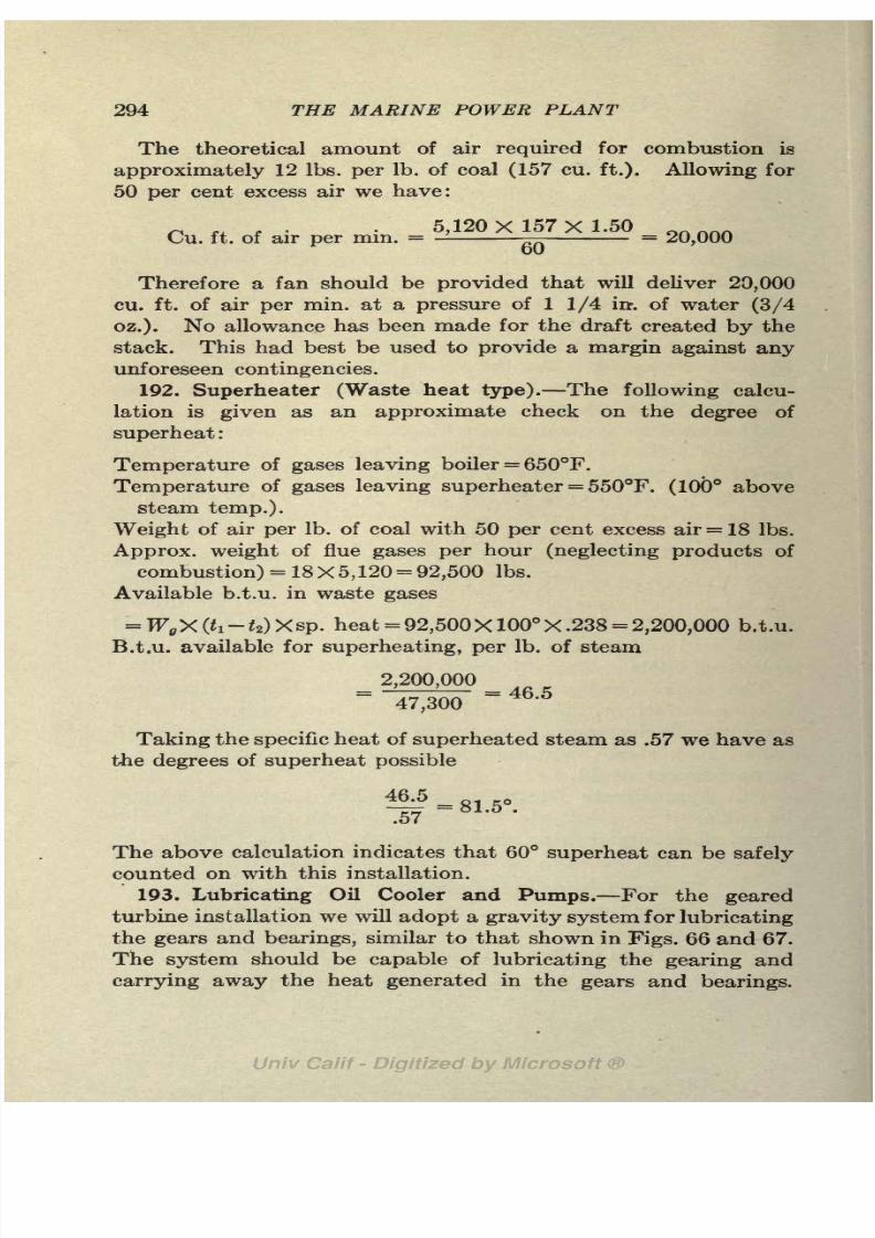
8/3/2019 Marine Power Plant Chaprich
http://slidepdf.com/reader/full/marine-power-plant-chaprich 306/335
294 THE MARINE POWER PLANT
The theoretical amount of air required for combustion is
approximately 12 Ibs. per Ib. of coal (157 cu. ft.). Allowing for
50 per cent excess air we have:
Cu. ft. of air per min. = 5,120 X 157 X 1.50 _OU
Therefore a fan should be provided that will deliver 20,000
cu. ft. of air per min. at a pressure of 1 1/4 in-, of water (3/4
oz.). No allowance has been made for the draft created by the
stack. This had best be used to provide a margin against any
unforeseen contingencies.
192. Superheater (Waste heat type). The following calcu-
lation is given as an approximate check on the degree of
superheat :
Temperature of gases leaving boiler = 650F.
Temperature of gases leaving superheater= 550F. (100 above
steam temp.).
Weight of air per Ib. of coal with 50 per cent excess air= 18 Ibs.
Approx. weight of flue gases per hour (neglecting products of
combustion) = 18X5, 120 = 92,500 Ibs.
Available b.t.u. in waste gases
=W X(ti-t2)Xsp. heat = 92,500X 100 X.238 = 2,200,000 b.t.u.
B.t.u. available for superheating, per Ib. of steam
2,200,000 " 46 -5
Taking the specific heat of superheated steam as .57 we have as
the degrees of superheat possible
46.5
^7
The above calculation indicates that 60 superheat can be safely
counted on with this installation.
193. Lubricating Oil Cooler and Pumps. For the geared
turbine installation we will adopt a gravity system for lubricating
the gears and bearings, similar to that shown in Figs. 66 and 67.
The system should be capable of lubricating the gearing and
carrying away the heat generated in the gears and bearings.

8/3/2019 Marine Power Plant Chaprich
http://slidepdf.com/reader/full/marine-power-plant-chaprich 307/335
COMPUTATION FOR POWER PLANT 295
If we assume the efficiency of the gearing and bearings as 93
per cent, which is somewhat worse than good practice, the
lubricating oil will have to carry away,
2,700 X.07X2,545 =^^ per^Assume the following conditions for the coolers:
h= Temperature of circulating water inlet = 60F.
tz= Temperature of circulating discharge
= 90.
fa
=Temperature of lubricating oil entering cooler
=120.
I*= Temperature of lubricating oil leaving cooler = 100.
Lubricating oil required per minute
b.t.u. per min. 8,000 Rq9
03-
U) X sp. heat of oil
~(120
-100) X .48
~
Allowing the weight of oil as 7.3 per gallon we have:
832
y^ = 114 g.p.m.
The combined suction and discharge heads for the lubricating
oil pumps when the gravity tanks are located 30 ft. above the
turbine shaft would be about 40 ft.
To this head should be added the velocity head of the oil and
the losses due to pipe friction bends and valves, and the loss
through cooler.
Velocity head of oil at 3 ft. per sec negligible
Loss head pipe friction bends and valves (with oil
velocity of 3 ft. per sec.) approx 20 ft.
Loss through cooler (10 Ibs./sq. in.) 27 ft.
Suction and discharge head 40 ft.
Total head required at pump 87 ft.
Hp. of lubricating oil pump at 60 per cent efficiency
832 X 87
33,000 X .60
b.t.u. to remove per min.
Cooling water required= -
_
3.7 hp.
'emovt
ti-ti

8/3/2019 Marine Power Plant Chaprich
http://slidepdf.com/reader/full/marine-power-plant-chaprich 308/335
296 THE MARINE POWER PLANT
As already pointed out, the pressure of the oil in the cooler
should be greater than that of the water so that if there is any
leakage it will be the oil leaking into the circulating water. This
requires that the cooler be designed so that the resistance of the
circulating water is less than 10 Ibs. per sq. in. Allowing 21 ft.
as the total head required at the pump, we have :
Horsepower of circulating pump at 50 per cent efficiency
267 X 21
33,000 X .50
= 0.34 h.p.
As the sea water may at times reach a temperature much
higher than 60 the rise in temperature of the cooling water maybe only 10 instead of the 30 allowed. Under these conditions
1.00 hp. would be required. A pump and motor capable of
this increased duty should be installed.
In this installation it is proposed to use motor driven pumpsfor both oil and cooling water. A direct acting lubricating oil
pump should be installed as a stand-by.
194. Fuel Oil System. In order that the fuel oil will have a
low viscosity so that it will atomize in the burners it must be
heated to between 100 and 240F., depending on the kind of
oil used.
With following conditions existing we can now calculate the
amount of steam from the auxiliary line required for heating
the fueloil.
Fuel oil required per hour (see boiler calculations)=2,620 Ibs.
Temperature of oil in tanks (assumed) 60F
Temperature of oil at burners 200F.
Specific heat of oil 0.50
Efficiency of heater, per cent 85
Temperature of drip leaving heater 250
Heat of vaporization at 100 Ibs. gage 880 b.t.u.
Heat in liquid above 250 90 b.t.u.
Heating steam required
2,620 X .50 X (200-
60)
(880 + 90) X.85= 222 lbs ' per hour '
When the temperature of the oil in the fuel oil tanks is too
low to be handled by the pumps a heating coil has to be fitted

8/3/2019 Marine Power Plant Chaprich
http://slidepdf.com/reader/full/marine-power-plant-chaprich 309/335
COMPUTATION FOR POWER PLANT 297
at the end of the suction line. The efficiency of such a coil will
be much lower than the heater. In view of thesepossibilities,
300 Ibs. of steam is a fair allowance for heating the fuel oil.
195. Fuel Oil Pumps. Two oil pumps are required: one, the
booster or transfer pump, draws the oil from the tanks and de-
livers it to the fuel oil tanks amidships or settling tanks in the
fire room; the other, the fuel oil service pump, takes the oil from
the discharge of the booster pump and discharges it through
the heaters to the burners. The service pumps are always
fitted in
duplicate,one
servingas a
stand-by pump.The exact division of the total head between these pumps varies
with different installations. For our present purpose, where the
steam necessary is all that is required, the horse power of the
two will be combined.
The oil pressure necessary at the burners varies between 100
and 200 Ibs. per sq. in. 160 Ibs. per sq. in. will be allowed in
this case.
FeetHead required at burner (160 Ibs./sq. in.) 430
Suction and discharge heads 10
Pipe friction, head lost in bends, valves, strainers, manifolds,
etc 70
Head lost through heater 20
Total head required for pumps 530
Fuel oil per hour = 2,620 Ibs.
Oil h.p. required=g|X|30
= 0.70 hp.
Allowing say 1.0 h.p., required in the oil cylinders of the pumps,
we have
Steam required per hour = 100X1.0 = 100 Ibs.
(The steam consumption of direct acting pumps is generally
figured in Ibs. per water horsepower per hour and varies between
100 and 125 Ibs. per w.h.p. par hour.)
196. Feed and Filter Tank. The feed and filter tank should
have sufficient capacity to hold at least fifteen minutes' supply
of fesd water.

8/3/2019 Marine Power Plant Chaprich
http://slidepdf.com/reader/full/marine-power-plant-chaprich 310/335

8/3/2019 Marine Power Plant Chaprich
http://slidepdf.com/reader/full/marine-power-plant-chaprich 311/335
COMPUTATION FOR POWER PLANT 299
low value of the air richness ratio (P9/P t) has been chosen and a
cleanliness factor of .90 assumed.
10 cu. ft. per min. = 600 cu. ft. per hour = 45.5 Ibs. free air per
hour.
Ratio air to steam by weight at entrance of condenser
45.5
27,000.0017
Thus every pound of steam contains .0017 Ib. of air. Under these
conditions the partial pressure of the air is negligible at the top
of the condenser.
(a) Circulating Water. Salt water is circulated through the
condenser to condense the steam by carrying away the heat of
vaporization. The formula for heat transfer in b.t.u. per sq.
ft. per degree difference per hour, is
U = 350 CiC2 (Ps/PtY VV (Art. 167)
Ci = .90 for cleanliness factor.
Cz = .98 for admiralty tubes.
(P8/Pt)= .90 (assumed)
(P8/P<)2 = -81
Hot well temperature (air pump suction)= 67
U = 350 X.90 X.98 X.SIX 2.83 = 705 b.t.u. per degree difference
per hr.
The heat (H) to be removed by the cooling water is the heat
of vaporization in the exhaust steam at 29 in. vacuum.
Actually, H = (H 2 qs)X steam per hour =(x2r2+q2 q3) X
steam per hour, where H2 is total heat at vacuum temperature
and #3 is heat of liquid at hot well temperature.
For the turbine under investigation the quality after adiabatic
expansion from 275 Ibs. and 100 superheat to 29 in. was 0.77.
In the actual turbine, due to friction, etc., the quality would be
about .92. In order to be on the safe side we will assume dry
steam at exhaust. H 2 at 79 =1,094.2, $3 at 67 =
35.1, H2-q3=
1,059.1.
H= 1,059X27,000=28,600,000 b.t.u. per hr. to be removed
by cooling water.

8/3/2019 Marine Power Plant Chaprich
http://slidepdf.com/reader/full/marine-power-plant-chaprich 312/335
300 THE MARINE POWER PLANT
Quantity of cooling water (Q) per hr. in Ibs.
_B.t.u. to be removed per hour
i(et) - /2 (inlet)~~
Q = 28,600,000/ (67 -55) =2,380,000 Ibs./hr.
Q = 2,380,000/(60X8.55) =4,630 g.p.m.
Ratio of cooling water to condensed steam (Q/W) =2,380,000/
27,000= 88.
It is interesting at this point to note the large amount of
coolingwater
requiredwith
highvacua. Due to the low tem-
perature existing in the bottom of the condenser with 29 in.
vacuum, namely 67, and the lowest advisable temperature to
use for the sea water (55), there is a difference in temperature
of only 12 between the inlet and discharge of the cooling water.
With a vacuum of 25 1/2 in. the temperature in the bottom of
the condenser would be about 118 (13012). Using the same
sea temperature this would give a temperature difference of 63
between inlet and discharge which would require only one-fifth
as much cooling water for the same b.t.u. per hour. We thus
see that the cost of producing a vacuum of 29 in. requires a very
large increase in size and power of circulating pump. Later on
we will see that the sizes of the condenser and air pump are also
greatly increased for high vacua.
(6) Cooling Surface. The mean temperature difference be-
tween the steam and water (tm) is,
2
where t$= initial temperature difference (79 55)
U = final temperature difference (79 67)
Generally an arithmetic mean can be used without any appre-
ciable error. In this case the arithmetic mean is
79_(6755) =
Due to the fact that the temperature within the condenser is
less at the bottom than at the top (in this case 12 lower), the
above method of arriving at a mean temperature difference is
in error. However, the constant 350 was found from condenser

8/3/2019 Marine Power Plant Chaprich
http://slidepdf.com/reader/full/marine-power-plant-chaprich 313/335
COMPUTATION FOR POWER PLANT 301
tests using this method of arriving at the mean temperature;
hence the resultswill
beconsistent.
28,600,000Coolmg surface required
= _ _ _ = 2,400 sq. ft.
/Uo /\ 1 /
Allowing 10 per cent for margin we have c. s. = 2,640 sq. ft.
Condensation per sq. ft. c.s. = -c
- = 11.25Z,4UU
Cooling surface per s.h.p. ='
= .98 sq. ft.
^, /uu
(c) Condenser Tubes. Two sizes of tubes are in common use
3/4 in. & 5/8 in. o.d. Calculations will be carried through for
both sizes. The 3/4 in. tubes give a much more satisfactory
condenser than the 5/8 in. tubes on account of the smaller num-
ber of tubes required. The 5/8 in. tubes, however, give a lighter
condenser. Tubes of 3/4 in. diameter are used as a rule for
condenser on merchant ships and 5/8 in. diameter on naval
vessels. In land installations where the circulating water is
liable to be dirty 1 in. and sometimes 1 1/4 in. tubes are used.
Using 5/8 in. tubes (18 B.W.G.) :
o.d. = .625 in.
i.d. = .537in.
Outside surface per lineal ft. = .164 sq. ft.
Area through one tube=.00157 sq.
ft.
Quantity of water per sec. = 10.45 cu. ft. (4,700 g.p.m.)
Velocity of water through tubes = 8 ft. per sec.
Cooling surface = 2,640 sq. ft.
Number of tubes required= ' = 832
.UUlO/ Xo
u _ cooling surface in sq. ft. _ 2,640
"No. of tubes X surface area per ft.
"832 X. 164
Length= 19.35 ft. for one pass condenser (832 tubes)
= 9.67 ft. for two pass condenser (1,664 tubes)
Using 3/4 in. tubes (18 B.W.G.) :
o.d. = .75 in.
i.d. = .652 in.

8/3/2019 Marine Power Plant Chaprich
http://slidepdf.com/reader/full/marine-power-plant-chaprich 314/335
302 THE MARINE POWER PLANT
Outside surface per lineal ft. = .196 sq. ft.
Area through one tube = .00232 sq. ft.
Number of tubes required=
r.rtooo . -5= 564
X o
o
Length of tube - - 24 ft.
Length = 24 ft. for one pass condenser (564 tubes)
= 12 ft. for two pass condenser (1,128 tubes)
A layout can now be made for the condenser with the proper
length, area of tube sheet, etc. Experience with the details of
condenser construction is, of course, necessary in order to draw
up a suitable condenser.
(d) Vacuum in the Tropics. To illustrate the loss in vacuum
that a ship will experience in tropical waters, the following calcu-
lation is given :
ti (sea temperature)= 75
Condenser temperature possible with circulating water leaving
condenser at a temperature 12 below that of steam in condenser
and with a 10 rise in cooling water:
75+ 10+12 = 97 (vacuum corresponding= 28 1/4 in.)
Temperature of inlet water= 75
Temperature of exit water=85
Temperature of top of condenser= 97
With this falling off in vacuum there will be a reducing in
s.h.p. of the engines and an increase in the steam consumption
per s.h.p. If, however, we allow the same total steam as before,
we have:
(97-
75) -(97- 85) _ 10
1.83 .604
~
Both U and tm are practically the same as before;so the cooling
surface is sufficient.
The heat to be removed = (H2-q 8 5) X 27,000
= 1,049.3X27,000=28,300,000 b.t.u. per hour.
28,300,000
(85-
75) X 60X8.555
'5

8/3/2019 Marine Power Plant Chaprich
http://slidepdf.com/reader/full/marine-power-plant-chaprich 315/335
COMPUTATION FOR POWER PLANT 303
This brings out the fact that the circulating pump should have
a reservedcapacity
over that calculated to allow for
tropicalconditions and also for possible increases in steam consumption
over that allowed.
A vacuum somewhat higher than 28 1/4 in. could be produced
with sea water at 75 if a larger quantity of cooling water
were used. This, however, would increase the velocity of the
water through the tubes and call for a pump delivering not only
a larger quantity of water but at a greater pressure due to the
increased head causedby
thehigher speed
of the waterthrough
the tubes.
198. Condensers for Low Vacua. For low vacuum condensers
where the rise in the temperature of the cooling water between
inlet and discharge is large, the speed of the cooling water will
have to be reduced in order to keep the length of the condenser
down. With a high velocity of the cooling water, the number
of tubes required to give the proper area to pass the cooling
water through (Q=
av) is greatly reduced; and in order to getthe required cooling surface with the smaller number of tubes
long tubes would have to be used.
Speeds of 3 to 5 ft. per second should be used with installations
of this type and the discharge temperature of the cooling water
should not be allowed to exceed much over 100F. As already
pointed out, temperatures higher than this will cause trouble by
scale forming on the tubes. An example of an extreme case will
make this clear:
Vacuum = 26 in. (125F.)
Inlet temperature= 55F.
Discharge temperature = (125-12) = 113.
Steam condensed per hour = 46,400 Ibs.
B.t.u. to be removed per hour = 48,000,000=(1,033X46,400).
Cooling water per hour =
4
i
8
iQ>(
iT = 827,500 Ibs. per hour (3.59 cu. ft./sec.)llo oo
Cooling surface required=2,268 sq.ft. (allowing 10 per cent
excess as before).
3/4 in. tubes (18 B.W.G.)
Cross sectional area (inside)= .00232 sq.ft.
Cooling surface per foot of length= .196 sq.ft.

8/3/2019 Marine Power Plant Chaprich
http://slidepdf.com/reader/full/marine-power-plant-chaprich 316/335
304 THE MARINE POWER PLANT
Number of tubes in one pass=
3'
59*
f 6o o
.00232 X 8= 194 tubes with velocity of 8 ft. /sec.
2 268
Length of two pass condenser = -'
1%X 1/2
= 30.00 ft.
If speed of cooling water is taken as 4 ft. per second, we have:
oorjf)
Length =196
X 1/2= 21 ft. for two pass
A reduction in the speed of the cooling water decreases U
and hence increases the cooling surface as the square root of
the change in velocity, and increases the number of tubes
directly as the change. Hence the net result is that the length
of the condenser changes as the square root of the change in
velocity
199. Condenser for Reciprocating Engine Installation.
Vacuum in condenser= 27 in. (115F.)
Steam condensed per hour = 40,600 Ibs.
ti (at entrance) =55F.
t* (atexit)=90F. (115-25).
V =4 ft. per sec.
Temperatures of sea water greater than 90 or 100F. are
liable to cause scale unless the speed of the circulating wateris sufficiently high.
t/ = 350X.90X.98X.8lX4= 500 b.t.u. per degree difference
per hour.
Hot well temperature (air pump suction)= 105F. (115-10).
#2-tfio5= 1,110-73 = 1,037.
# = 1,037X40,600=42,150,000 b.t.u. to remove per hour.
42,150,000Q -
(90-
55) X 60 X 8.55= 2
>35 g 'P 'm -
_ (115-55)- (115-90) =
35tm ~ '
log, 60/25 .875
Cooling surface =' '
4Q=
2,110 sq. ft.
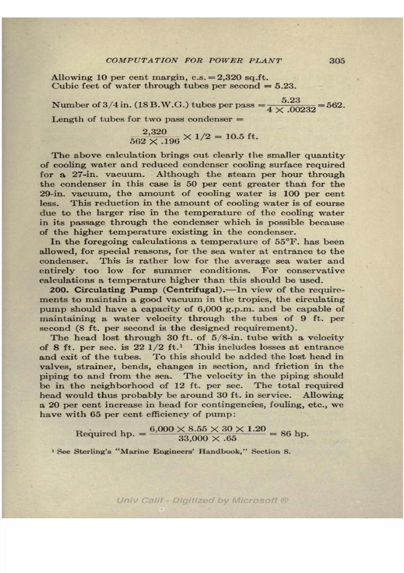
8/3/2019 Marine Power Plant Chaprich
http://slidepdf.com/reader/full/marine-power-plant-chaprich 317/335
COMPUTATION FOR POWER PLANT 305
Allowing 10 per cent margin, c.s. =2,320 sq.ft.
Cubic feet of water through tubes per second = 5.23.
c OQNumber of 3/4 in. (18 B.W.G.) tubes per pass
=j-^ ^- = 562.4
Length of tubes for two pass condenser =
The above calculation brings out clearly the smaller quantity
of coolingwater
andreduced condenser
cooling surface requiredfor a 27-in. vacuum. Although the steam per hour through
the condenser in this case is 50 per cent greater than for the
29-in. vacuum, the amount of cooling water is 100 per cent
less. This reduction in the amount of cooling water is of course
due to the larger rise in the temperature of the cooling water
in its passage through the condenser which is possible because
of the higher temperature existing in the condenser.
In the foregoing calculations a temperature of 55F. has beenallowed, for special reasons, for the sea water at entrance to the
condenser. This is rather low for the average sea water and
entirely too low for summer conditions. For conservative
calculations a temperature higher than this should be used.
200. Circulating Pump (Centrifugal). In view of the require-
ments to maintain a good vacuum in the tropics, the circulating
pump should have a capacity of 6,000 g.p.m. and be capable of
maintaining a water velocity through the tubes of 9 ft. per
second (8 ft. per second is the designed requirement).
The head lost through 30 ft. of 5/8-in. tube with a velocity
of 8 ft. per sec. is 22 1/2 ft.1 This includes losses at entrance
and exit of the tubes. To this should be added the lost head in
valves, strainer, bends, changes in section, and friction in the
piping to and from the sea. The velocity in the piping should
be in the neighborhood of 12 ft. per sec. The total required
head would thus probably be around 30 ft. in service. Allowing
a 20 per cent increase in head for contingencies, fouling, etc., we
have with 65 per cent efficiency of pump:
6,000 X 8.55 X 30 X 1.20
Required hp '-
33,000 X .65
= 86 hp '
1 See Sterling's "Marine Engineers' Handbook," Section 8.

8/3/2019 Marine Power Plant Chaprich
http://slidepdf.com/reader/full/marine-power-plant-chaprich 318/335
306 THE MARINE POWER PLANT
201. Condensate Pump. If an injector type of air pump is
used, as the "Radojet" which is used in this case, a condensate
pump must be installed to handle the condensed water from
the condenser and the condensed steam used by the first stage
of air pump. (See description of "Radojet" air pump with
intercondenser.)
This pump will have to raise the water from a pressure cor-
responding to 29 in. to atmospheric pressure, or 33 ft. Allow-
ing for pipe friction, entrance losses, etc., and a small lift to
feed tank, the total head will probably be around 40 ft.
Water handled per hour, 27,000+900 = 27,900 Ibs.
Allowing 60 per cent as the efficiency of the pump we have :
In this installation we will use a motor driven centrifugal
pump.
Hp. input at 77 per cent motor efficiency= 1.2 hp.
202. Boiler Feed Pump. Feed per hour under the best
conditions = 33,000 Ibs.
The capacity of the pump should be twice the rated con-
sumption so that it can take care of any sudden overload or
bring the level of the water in the boiler back to normal quickly
in case it should fall for any reason. Boiler feed pumps must
be fitted in duplicate, one for a service pump and one for a
stand-by. The feed pump must overcome the boiler pressure
and the lost heads due to pipe friction, bends, valves, and feed
heater and in addition produce a head sufficient to create a
velocity of flow into the boiler. In this case where the boiler
pressureis 270 Ibs., a head of 300 Ibs. should be allowed at
entrance to the boiler. An estimate of the lost heads for this
installation indicates a total loss of about 50 ft. with a possible
loss of 100 ft. due to partially closed valves.
In the selection of a boiler feed pump we have a choice between
several types of direct acting reciprocating pumps and a centrif-
ugal pump. At high pressures the centrifugal pump gives
a much more even delivery and avoids the shock caused by

8/3/2019 Marine Power Plant Chaprich
http://slidepdf.com/reader/full/marine-power-plant-chaprich 319/335
COMPUTATION FOR POWER PLANT 307
reciprocating pumps Hence it is easier on the piping, check
valves, etc. Also the steam consumption of a direct
actingpump is more than twice that of a turbine driven pump; and in
this installation it can be foreseen that the auxiliary exhaust
steam for feed heating is running high.
A turbine driven centrifugal pump will be selected for the
service pump with a direct acting vertical simplex pump as
a stand-by. An efficiency of 65 per cent can be counted on
for a centrifugal type of pump and efficiencies better than this
maybe
expected.
300 Ibs. sq.in.=a head of 300X2.30 = 690 ft.
, , 33,000 X 2 X 790MaX ' hp '
=33^00 X 60 X.65
= 4 -5hp '
c . , 33,000 X (690 + 50)Semce hp '
'
33,000 X 60 X .65
= 19 hp '
Required pump: 130-65 g.p.m.; head 790 ft.
This will probably require a three stage pump.
203. Evaporator. An allowance should be made for a make-
up feed in service of 5 per cent which in this case is 1,400 Ibs./hour.
This value is much less than common practice but is none too
low for a good installation using superheat steam where careful
attention is given to small leaks. The capacity of the evap-
orator should be somewhat greater than twice this allowance or
about 30 tons per 24 hours. Most cargo ships that are fitted
with evaporators have single effect evaporators. For the best
economy, however, only double effect evaporators should be
considered. The following rates for steam used by evaporators
are taken from the Journal of the A. S. N. E., Feb., 1914:
1 Ib. steam at 50 Ibs. will evaporate (single effect) 0.8 Ib.
water per hour.
1 Ib. steam at 50 Ibs. will evaporate (double effect) 1.45 Ibs.
water per hour.
1 Ib. steam at 50 Ibs. will evaporate (triple effect) 1.95 Ibs.
water per hour.
If a triple effect evaporator is fitted with evaporator feed heater
using steam from third effect the evaporation will be 2.35 Ibs.

8/3/2019 Marine Power Plant Chaprich
http://slidepdf.com/reader/full/marine-power-plant-chaprich 320/335
308 THE MARINE POWER PLANT
water per hour per pound of steam. With a double effect
evaporator 1 Ib. steam at 50 Ibs. gage will evaporate about
1.45 Ibs. of water. Allowing this evaporation, 1,400 Ibs. make-
up feed will require:
1 400
TF- Ibs. = 970 Ibs. of steam at 50 Ibs. gage.
204. Auxiliaries. In the merchant service the auxiliaries are
supplied by a dry steam line which leaves the boilers before
the steam has been passed through the superheater. In some
ships, especially in the U. S. Navy, full boiler pressure is used
on all the auxiliaries. The better practice is to use reduced
pressure on the auxiliaries except direct acting boiler feed pumps.
In this case where a centrifugal feed pump is used reduced
pressure can be used on all the auxiliaries. Reducing the
pressure, which is a constant heat contents change, results in
superheating the steam and thus avoids the losses due to con-densation and drip from pipes, valves, valve chests, etc.
If for the case under consideration the pressure in the
auxiliary line is reduced from dry steam at 285 Ibs. abs. to 100
Ibs. gage, we have from the Mollier diagram:
H l at 285 Ibs, dry=
1,203 b.t.u.
At 115 Ibs. abs. and 1,203 b.t.u. (constant heat line) the steam
is at about 25 superheat.
All the auxiliaries exhaust to the auxiliary exhaust line at
5 Ibs. gage, and the auxiliary exhaust line delivers the steam to
the feed heater.
In some installations there is a cross-connection from the
superheated steam line to the auxiliary saturated steam line and
the auxiliaries are started on saturated steam and thenoperatedwith superheated steam. This procedure, of course, could not
be used when a reduced steam pressure is used on the auxiliaries.
In fact, using superheat with auxiliaries has very little to
recommend it.
We are now ready to tabulate our auxiliaries and make an
estimate of the steam used by each. The following steam
consumptions have been allowed and are representative figures

8/3/2019 Marine Power Plant Chaprich
http://slidepdf.com/reader/full/marine-power-plant-chaprich 321/335
COMPUTATION FOR POWER PLANT 309
ESTIMATE OP STEAM CONSUMPTION FOR AUXILIARY MACHINERY 2,700 S.H.P.
GEARED TURBINE WITH OIL FIRED BOILERS
Auxiliary

8/3/2019 Marine Power Plant Chaprich
http://slidepdf.com/reader/full/marine-power-plant-chaprich 322/335
310 THE MARINE POWER PLANT
for turbines and reciprocating engines working between 100 Ibs.
gage and atmospheric exhaust:
Direct acting steam pumps 100-125 Ibs. per water hp. per hr.
Geared turbines, 25 h.p., 40-50 Ibs. per s.h.p. per hr.
Geared turbines, 100 h.p., 35 Ibs. per s.h.p. per hr.
Reciprocating engines, 10 h.p. 60 Ibs. per s.h.p. per hr.
Weir air pumps 1 per cent total steam.
"Radojet" air pump (See A.S.N.E. Journal, Aug., 1920).
"Radojet" air pump with intercondenser, handling 10 cu. ft.
free air per min. at 29 in. = 860 Ibs.
"Radojet" air pump without intercondenser, handling 10
cu.ft. free air per min. at 29 in. = 1,700 Ibs.
The preliminary estimate for^the steam for auxiliaries was
5,400 Ibs. per hour (20 per cent). The new figure by independent
estimate is 6,390 Ibs. per hour or 23.6 per cent of that used by
the main engines. The total increase in the steam required is
990 Ibs. or practically 3 per cent increase hardly enough to
warrant an increase over our preliminary estimate for heating
surface.
205. Calculations for Feed Heating.
Estimated Steam Consumption: Lbs.
Steam used by main engine per hour 27,000
Auxiliary exhaust at 5 Ibs. gage to feed heater . . . 4,220
Radojet, evaporator and oil heater drip 2,170
Steam for heating1 600
Total steam per hour 33,990
Heat available in feed tank:
B.t.u. available above 32F. :
In make-up feed (5 per cent) at B.t.u.
200F. fromevaporator
2
1,400X 168= 235,000In condensate from condenser at
67 2
25,600X 35= 897,000
In auxiliary exhaust drip from
feed heater at 228 4,220X 196 = 828,000
1 For convenience, drips from heating steam taken at 125.8 For convenience all the make-up feed assumed to be lost from main
engine steam.

8/3/2019 Marine Power Plant Chaprich
http://slidepdf.com/reader/full/marine-power-plant-chaprich 323/335
COMPUTATION FOR POWER PLANT 311
In evaporator drip at 250 ........ 970X 218 = 212,000
In oil heater drip at 250 ......... 300X 218 = 65,500
In Radojet exhaust 3 ............. 900X1,000= 900,000
Total b.t.u. in feed tank above 32F............ =3,137,500
o -1 07 con
Temperature of water in feed tank =32+33
Heat available in a pound of auxiliary exhaust = heat of
vaporizationat 5 Ibs.
gage.Total heat available in auxiliary exhaust = 959X4,220 =
4,050,000 b.t.u. per hour.
Allowing an efficiency of 90 per cent for the heater due to
radiation, we have for the temperature of the feed water at
entrance and exit of feed heater:
Temperature of feed entering heater = 125F.
4 050 000
X90
Rise in temperature in feed heater = - n- = 107F.
Temperature of feed leaving heater = 125+107 = 232.
It will be observed that the calculated temperature of the
feed water is 4 higher than the temperature of the heating
steam. With a closed heater the feed water can as a rule be
heated to within about 10 of the steam temperature. In this
case the maximum temperature possible for the feed water would
be about 218 (228-10). The foregoing calculations, which show
that the temperature is greater than that of the heating steam,
of course, simply indicates that there is more heating steam
available than can be used.
In a case such as this we have four alternatives: (1) Better
designed auxiliaries, using less steam, could be installed; (2) the
steam pressure in the exhaust line could be increased, thus
increasing the temperature of the steam entering the heater;
(3) part of the exhaust steam could be discharged into the low
pressure stages of the main turbine;or (4) a series heat could be
employed with part of the exhaust steam at a higher pressure.
'Radojet fitted with intercondenser but heat accounted for in this
manner.

8/3/2019 Marine Power Plant Chaprich
http://slidepdf.com/reader/full/marine-power-plant-chaprich 324/335
312 THE MARINE POWER PLANT
If a separate coil were fitted in the discharge end of the heater
supplied with exhaust from the direct acting steam pumps,
which discharge at a much higher pressure than the other
auxiliaries, a certain amount of steam would be available at
a temperature higher than 228. This would allow the feed to
be heated to a higher temperature. The series coil might be
connected to the drips from oil heaters, evaporators, etc., which
are at a higher temperature than 228; or the back pressure on
certain auxiliaries might be carried higher than 5 Ibs. gage and
this exhaust sent
throughthe second coil of the feed heater.
While the use of a series feed heater offers an opportunity for
better economy and a higher feed temperature, it would require
two separate auxiliary exhaust lines and otherwise complicate
the piping. Hence, this installation would not appeal to many
shipowners, and the best solution would be to use the surplus
exhaust in the L.P. turbine. In no case should continuous surplus
of exhaust steam be sent to the auxiliary condenser.
Ordinarily the drains from the heating system when in opera-
tion are led to the feed tank. As the heating eteam is at a low
pressure and very small in quantity compared to the total feed,
no allowance has been made for it in the foregoing calculations.
If the make-up feed had been drawn from the make-up feed
water tank in the double bottom instead of being evaporated
from salt water our feed temperature would be slightly lower.
The general practice in merchant ships is to draw the make-up
feed up from the double bottom through a connection to the
main condenser. Thus the vacuum in the condenser serves to
lift the water from the tank. The make-up feed mixes with the
condensate in the bottom of the condenser. While this is a
very simple and convenient arrangement, it is not to be recom-
mended in high vacuum installations.
In the foregoing calculations for feed heating, the exhaust
from the auxiliaries has been assumed dry and the total heat of
vaporization has been assumed available for feed heating. The
steam in the auxiliary line is obtained by reducing steam at
full boiler pressure (270 Ibs. gage) down to 100 Ibs. gage which
gives the steam in the auxiliary line a superheat between 20
and 30F. (Art. 10). This amount of superheat is sufficient to
allow for all radiation losses and to insure dry steam at the
throttle of all auxiliaries. An adiabatic expansion from dry

8/3/2019 Marine Power Plant Chaprich
http://slidepdf.com/reader/full/marine-power-plant-chaprich 325/335

8/3/2019 Marine Power Plant Chaprich
http://slidepdf.com/reader/full/marine-power-plant-chaprich 326/335

8/3/2019 Marine Power Plant Chaprich
http://slidepdf.com/reader/full/marine-power-plant-chaprich 327/335
INDEX
Adiabatic expansion, 10
Analysis, of coal, 28
of flue gas, 73
of fuel oil, 31
proximate, 26
ultimate, 26
Air for combustion, 69, 71, 87, 289,
294
Air in condenser, 231, 234-238
Air in feed water heaters, 265
Air injection, 186
Air leakage, 231, 232
supplyfor
combustion, 71,87
Air pumps, Bethlehem-Weir, 258
Blake-Knowles, 259
dual, 256
dry air, 251
ejector type, 251
object of, 250
Radojet, 253
suction temperature, 238
Weir dual, 256
Westinghouse Le Blanc, 252
wet air, 251
with reciprocating engines, 243
Atomization of oil, 82
Augmentor, Parsons, 251
Auxiliaries, 308-313
electric, 270
B
Babcock & Wilcox (see boiler)
Back pressure, 4, 121, 311
Baum6, 33
Boilers, Babcock & Wilcox, 46, 283
calculations for heating surface,
283-291
circulation, 63-64
Boilers, coal burning, 44, 66, 283, 289
efficiency, 61, 76
express, 35, 49
fire tube (see Scotch)
Foster, 35-46
furnace, 38, 86heat balance, 75
heating surface, 41, 52-57, 62
heat transmission, 52
horse power, 62
losses, 72-75
oil burning, 42, 45, 67, 288
performance, 52, 53, 57, 64, 66,
67
Scotch, 35-42, 61, 63, 76, 96,289
stresses, 262
temperature, 53-5, 76
tests, 61, 66, 67
water tube, 42, 63
Ward, 47
Yarrow, 49-51
Calorimeter, 13
Carbon dioxide, 69
Carbon monoxide, 69
Cargo deadweight, 228
Circulating pump, 305
Clausius cycle, 13
Coal, analysis, 24, 28
anthracite, 29
bituminous, 29
bunker, 78, 105
calorific value, 27, 29
classification, 26
compared with oil, 103-109
composition, 26
dry, 27
moisture in, 72
powdered, 30, 79
315

8/3/2019 Marine Power Plant Chaprich
http://slidepdf.com/reader/full/marine-power-plant-chaprich 328/335
316 INDEX
Coal, purchase of, 30
proximate analysis, 24
semi-bituminous, 29
Colloidal fuel, 108
Combination machinery, 171, 215
Combustible, 27
Combustion, air required for, 69, 71,
82,87
chemistry of, 68
excess air, 70
incomplete, 73
rate of, 59-60, 283
Comparison of propelling machinery,
211-229
two and four cycle, Diesel, 222
boilers, 63
coal and oil, 103-109
land and marine installations, 1
Compound (see reciprocating and
turbine)
Computations for power plant, 279-
313.
Cooling surface (see condenser)
Condensate pump, 306
Condensation, cylinder, 17-19, 115,
124
Condensers, ah* leakage, 231
auxiliary, 247
calculations, 298-304
contraflow, 280
cooling surface, 300
design, 298-304
heat transfer in, 23?
location, 243
Lovekin, 245
object of, 230
temperature in, 235, 298
thermodynamics of, 233
tubes, 301, 245
types, 240
Weir, 241
.Constant heat change, 12
Cycle, actual steam engine, 17
Clausius, 13
Diesel, 183
direct acting pump, 22
four, 183
Cycle, Otto, 184
Rankine, 13, 20
two, 183
Dalton's law, 233
"Delaware" U. S. S., 129, 116
Design (see auxiliaries, condenser,
turbine, etc.)
Diagramof
power plant,272
Diesel cycle, 128
electric drive, 180, 223, 228
fuel, 107, 220
Diesel engine, auxiliaries, 188
Burmeister and Wain, 199
circulating water, 189
Cammellaird-Fullagar, 199
control, 190
comparison, 219, 224-229
fuel injection, 186-188
geared, 224
losses in 5
lubrication, 189
mechanical efficiency, 192
Nelseco, 201
piston cooling;, 190, 195
reversing, 190
scavenging, 192
semi-Diesel, 203, 224
solid injection, 187
starting, 190
Sulzer, 195
two cycle, 185, 222
valve gear, 191
weights, 2, 229
Direct acting pumps, 23
Draft, 90
apparatus, 228
forced, 93
Draft, Howden, 37, 84, 94, 269
induced, 94
mechanical, 90, 93
natural, 91, 287
Draft, pressure, 90, 100-102, 293
Drips, 308-313
Dulong's formula, 29

8/3/2019 Marine Power Plant Chaprich
http://slidepdf.com/reader/full/marine-power-plant-chaprich 329/335
INDEX317
Economizers, 55, 268
Efficiency, boiler, 61, 76
Diesel cycle, 183
engine, 2
overall, 2
mechanical, 22
of Diesel, 192
plant, 2
Rankine, 15, 20
ratio, 19, 20, 21, 135, 152, 214,
227, 229, 280
thermal, 19, 20
turbine, 135
Electric drive, 174-182
advantages of, 174
comparison, 215
diagrams, 175, 177
Diesel electric, 180-182
data, 182
"Eclipse," 272-273
essential features of, 174
reversing, 179
motors, 175
Engine (see Diesel, Steam, Still, etc.)
Rankine, 13
real, 17
Entropy, 6
diagram, 9, 11, 14, 136
Engler viscosity, 34Equivalent evaporation, 57, 285
Evaporation, 57-58, 307
Excess air, 70
Expansion of steam, 10, 121, 133
Factor of evaporation, 58
Fans, 95, 99
Feed heaters
air in, 266
Bethlehem-Weir, 263
calculations, 308-313
closed, 263, 265, 267
high pressure, 265
low pressure, 265
open, 263
Reilly, 264, 267
Schutte and Koerting, 265, 268
series, 268
temperature, 308-313
two pass, 266
heating, 262, 310
tank, 297, 310
water, 263, 308-313
Floating frame, 162
Four cycle Diesel engine, 107, 185, 222
Fuel oil, analysis, 32
burners, 82, 84calorific value, 33
combustion of, 82
comparison with coal, 103-107
Diesel, 220, 107
flash point, 33
fire point, 33
furnaces for, 85
future supply, 106, 108
heater, 296
operation with, 86
pumps, 89, 297
properties of, 33
specific gravity, 33
systems, 296
viscosity of, 34
Gasoline engine, 224
Geared Diesel, 224
electric drive, 278
Gear arrangement, 164, 227-228, 267-
277
construction, 165
data, 173
Geared turbine, 159-171
compared to electric drive. 215
failures, 167
oiling systems, 167
Geared turbine, tooth pressure, 165,
166
torque variations, 163
two plane types, 165
types of gearing, 159
Grate surface, boiler, 62

8/3/2019 Marine Power Plant Chaprich
http://slidepdf.com/reader/full/marine-power-plant-chaprich 330/335
318 INDEX
H
Heat availability, 127
balance, 75
consumption, 22
losses in steam engine, 5, 19
losses in boiler, 72
of combustion of coal, 26, 29
of combustion of oil, 33
of vaporization, 7
transmission in condenser, 238
transmission in boilers, 52Heaters (see feed water heaters, fuel
oil heaters, etc.)
Heating surface calculations, 283-292
Horse power, boiler, 62
brake, 20
indicated 20, 22, 120
shaft, 20
Hot well pump, 264
Howden draft(see draft)
Incomplete combustion, 73
Indicated horse power, 20, 22, 120
Induction motor, 177
Initial pressure, 127
Intrinsic energy, 7
Liquid, heat of, 7
Losses in boiler, 72-75
heat, in engines, 19
in propelling machinery, 5
Lubricating oil, cooler, 295
for Diesel engines, 189
for geared turbines, 167
in feed water, 264
Lubricating oil pumps, 295
temperature, 295
M
Machinery arrangements, 197, 243,
227-228, 272-278
compared, 224
Mechanical draft, 90
Mechanical efficiency, 22
stokers, 77
Mollier diagram, 10
Motors (see electric drive)
Motorship data, 204, 221, 224, 228
"New Mexico," U. S. S.
electric drive, 179
machinery arrangement, 275
turbine, 144
NNozzle, steam, 133, 137
Oil (see fuel, lubricating, etc.)
Parsons' Turbine, 147Partial pressure, 233-238
Petroleum, 31
Port scavenging, 185, 195
Power plant diagram, 272
layouts, 273-278
Powdered coal, 30, 79
Pump, boiler feed, 306
circulating, 305
condensate, 306direct acting, 203
fuel oil, 89, 297
hot well, 264
lubricating oil, 294
Pressure, initial, 127
Pressure, partial, 233-238
Propeller, r. p. m , 2, 3, 212, 215
Proximate analysis, 26
Q
Quadruple expansion (see recipro-
cating)
Radojet vacuum pump, 253
Rankine cycle, 13
efficiency, 15

8/3/2019 Marine Power Plant Chaprich
http://slidepdf.com/reader/full/marine-power-plant-chaprich 331/335

8/3/2019 Marine Power Plant Chaprich
http://slidepdf.com/reader/full/marine-power-plant-chaprich 332/335
320 INDEX
Turbine, thermodynamics of, 135
velocity compounded, 140
Westinghouse, 153-155Two cycle Diesel engine, 185, 222
Vacuum, high, 157, 279
in condensers, 230-248
in tropics, 302
Vacuum, low, 303
withreciprocating
engines, 128
with turbines, 157
Vaporization, heat of, 7
Velocity of steam (see steam)
Viscosity of oil, 34, 170
Volatile matter in coal, 27
Volume of air in condenser, 234-238
W
Wager bridge wall, 71, 77
Wake, 166
Water tube boilers (see boilers)
Weight of boilers, 40, 57
fuel, 105
machinery, 2, 3, 227-228
Westinghouse air
pump,252
turbine, 153
Wet air pump, 25
Winches, deck, 247

8/3/2019 Marine Power Plant Chaprich
http://slidepdf.com/reader/full/marine-power-plant-chaprich 333/335

8/3/2019 Marine Power Plant Chaprich
http://slidepdf.com/reader/full/marine-power-plant-chaprich 334/335
UNIVERSITY OF CALIFORNIA LIBRARYBERKELEY
Return to desk from which borrowed.
This book is DUE on the last date stamped below.
MAY 7 1348
APR 8 6 1948
LD 21-100m-9,'47(A5702sl6)476

8/3/2019 Marine Power Plant Chaprich
http://slidepdf.com/reader/full/marine-power-plant-chaprich 335/335
YC 34147
THE UNIVERSITY OF CALIFORNIA LIBRARY