Embed Size (px)
Citation preview
n Ballast
n Bildge
n FireProtectionSystems
n FlareGasSystems
n InjectionWater
n InstrumentIsolation
n PumpSkids
n Sea-Chest
n UtilitySeawater
n WaterFlood
MARINE&OFFSHOREVALVES
www.pbmvalve.com
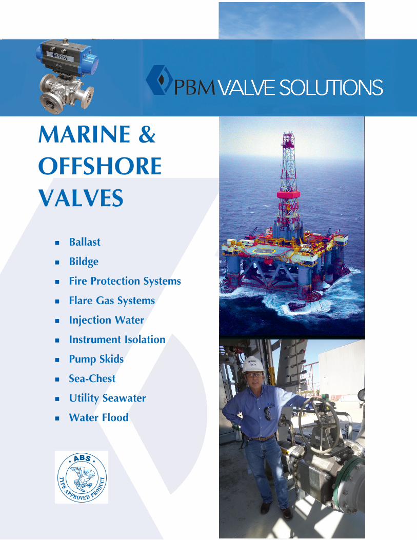
MARINE VALVE SOLUTIONS - ShIpbUILdINg - OffShORE ExpLORATION & pROdUcTION
3-PieceBronzeValve
PBMSeawaterValves-2-Way,DiverterPort, Multi-Port,&Instrument
n Services: Bilge, Ballast, Utility, Fire Protection, Flare, Pump Skids, Flood Water
n 3-piece Industrial valves* n 2-piece per ANSI B16.10 length* n Instrument valves* n Cryogenic valves - refining processes onboard FPSO, LNG
tankers,CNGfreighters
n Materials:Bronzes,StainlessSteels,Duplex,Monels,Hastelloys, CarbonSteel
n SeatMaterials Soft:TFMTM,S-TEF®,RTFE,PEEK Metal:Stellite,TungstenCarbide,ChromeCarbide
n Sizes:1/4”-12”
n PressureClasses:ANSICL150andCL300 n Ends:Flanges,ButtorSocketWelds,Threaded n BronzeandCopperNickelvalvetestingandacceptancecriteria
IAWMSSSP-72, allothermaterialsASTMB16.34andMSS-61 asapplicable
n CertifiedandMaterialTestReportsareavailablewhen requestedatthetimeoforder.
n PositiveMaterialIdentification(PMI)maybeavailablewhen requested.
n AmericanBureauofShipbulding(ABS)andU.S.CoastGuard requestedatthetimeoforder. n EUPressureEquipmentDirective(PED)pending n Automation:Electric,pneumaticandhydraulicautomation/control
packagesavailable
*FireTightDesign
ANSITrunnionANSIValve
www.pbmvalve.com
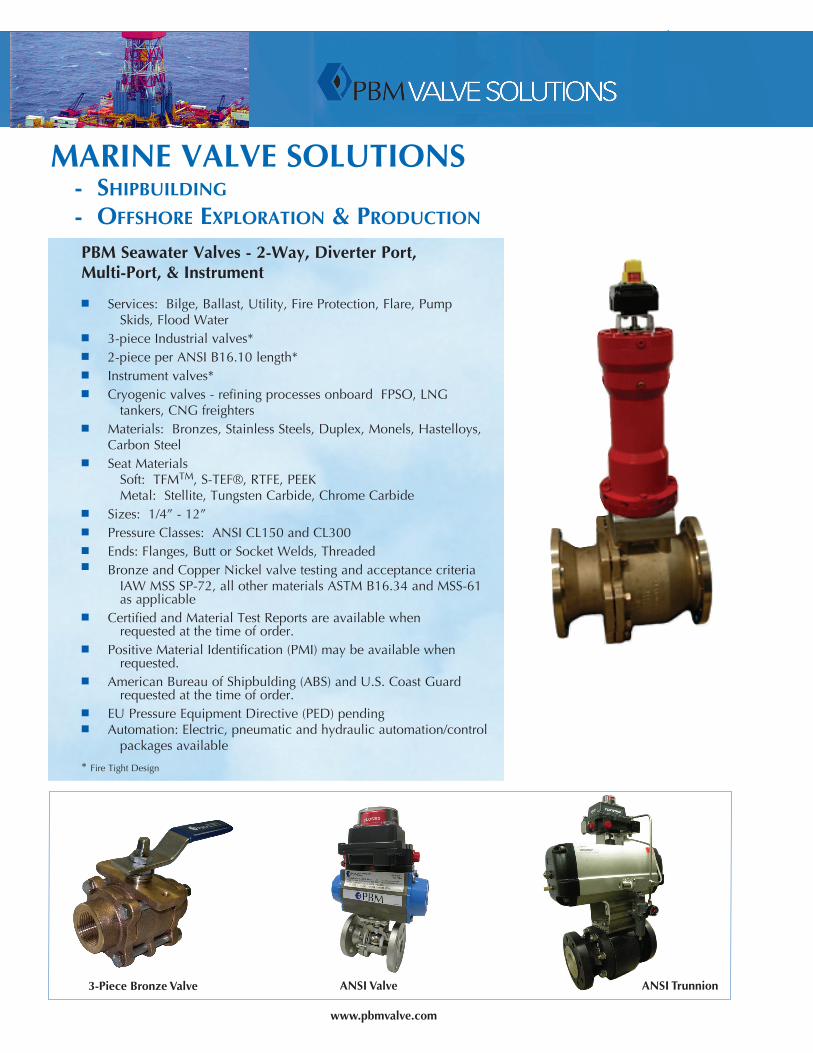
A
Sp SERIES 1 (836 bRONzE) SPSeries1seawatervalvesare3-piecevalvesavailableinfemaleNPT,socket-weld(forpipe),sil-braze(forpipe)and150#flangedendfittings.
Size
PortDiameter
A B C D E
FacetoFace CLtoFace HandleLengthfrom
CL
CLto
TopofHandle
CLtoBottom Approx.Wgt.
Q-S-U- L- Q-S-U- L-Q-S-U-
L- Q-S-U- L-
inch mm inch mm inch mm inch mm inch mm inches mm inch mm inch mm inch mm lb kg lb kg
1/4” DN8 0.62 16 3.12 79 - - 1.56 40 - - 6.09 155 3.03 77 1.34 34 - - 2 0.9 - -
1/2” DN15 0.62 16 3.12 79 5.38 137 1.56 40 2.69 68 6.09 155 3.03 77 1.34 34 1.81 46 2 0.9 5 2.3
3/4” DN20 0.81 21 3.45 88 5.75 146 1.72 44 2.88 73 6.09 155 3.15 80 1.47 37 1.88 48 3 1.4 6 2.7
1” DN25 1.00 25 3.90 99 6.30 160 1.95 50 3.15 80 8.69 221 3.53 90 1.69 43 2.13 54 4 1.8 9 4.1
1-1/4” DN32 1.25 32 4.54 115 7.26 184 2.27 58 3.63 92 8.69 221 4.90 124 1.57 40 2.31 59 8 3.6 15 6.8
1-1/2” DN40 1.50 38 5.36 136 6.98 177 2.68 68 3.49 89 8.69 221 5.08 129 1.71 43 2.50 64 10 4.5 17 7.7
2” DN50 2.00 51 5.75 146 8.43 214 2.87 73 4.21 107 8.69 221 5.45 138 2.03 52 3.00 76 13 5.9 25 11.3
2-1/2” DN65 2.50 64 8.36 212 10.86 276 4.18 106 5.42 138 12.44 316 5.50 140 2.81 71 3.50 89 33 15.0 52 23.6
3” DN80 2.75 70 8.62 219 12.04 306 4.31 109 6.02 153 12.44 316 6.82 173 3.88 99 3.88 99 49 22.2 77 34.9
4” DN100 3.50 89 10.46 266 12.90 328 5.23 133 6.45 164 12.44 316 7.32 186 4.50 114 4.50 114 84 38.1 115 52.2
NOTES: 1.SPSeriesvalveswith150#flangesare3-piecevalvesthatdonotmeetANSIfacetofacedimensions.UseANSeries2-pieceflangedvalvesifANSIfacetoface dimensionsarerequired. 2.ConsultPBMforactuatormountingdimensions. 3.Forflangedvalves,flangeholesstraddlethecenterlineexceptfortheSPSeries1,1-1/2”valves.
3
B
C
SocketWeldU-
ButtWeldB-,D-
150#FlangeL-
D
E
VALVEWEIGHT FACE-TO-FACEDIMENSIONS
SERIES1 SERIES5 SERIES1 SERIES5
StdBody/EndMaterial 836Bronze(B62,C83600)
922Bronze(B61,C92200)
836Bronze(B62,C83600)
922Bronze(B61,C92200)
Std.TrimMaterial 316StainlessSteel 316StainlessSteel 316StainlessSteel 316StainlessSteel
StandardSeat/SealMaterial RTFE(GlassFilledTeflon) TFMTM RTFE(GlassFilledTeflon) TFMTM
SwingOutDesign No Yes No Yes
BodyBoltPatterns Non-Symmetricon1/2”-1”and3”sizes
Symmetricpatternsonallsizes(4boltsupto3”,8boltson4”)
Non-Symmetricon1/2”-1”and3”sizes
Symmetricpatternsonallsizes(4boltsupto3”,8boltson4”)
ActuatorMounting Standardexcept1-1/4” Standard Standardexcept1-1/4” Standard
EndConnectionsFNPT,Sil-Braze,SW,SolderJoint
150#F.F.Flange
FNPT,Sil-Braze,SW,SolderJoint
150#F.F.Flange
FNPT,Sil-Braze,SW,SolderJoint
150#F.F.Flange
FNPT,Sil-Braze,SW,SolderJoint
150#F.F.Flange
Size lb kg lb kg lb kg lb kg in mm in mm in mm in mm1/2” DN15 2 0.9 5.0 2.3 2 0.9 4 1.8 3.12 79 5.38 137 3.12 79 5.50 1403/4” DN20 3 1.4 6.4 2.9 2 0.9 6 2.7 3.45 88 5.75 146 3.45 88 5.75 1461” DN25 4 1.8 8.6 3.9 5 2.3 9 4.1 3.90 99 6.30 160 4.25 108 6.50 165
11/4” DN32 8 3.6 14.5 6.6 - - - - 4.54 115 7.26 184 - - - -11/2” DN40 9.5 4.3 17 7.7 11 5.0 17 7.7 5.36 136 6.98 177 5.50 140 8.00 203
2” DN50 13 5.9 25 11.3 17 7.7 26 11.8 5.75 146 8.43 214 6.00 152 9.75 24821/2” DN65 33 15.0 52 23.6 37 16.8 53 24.0 8.36 212 10.86 276 8.00 203 11.50 292
3” DN80 49 22.2 77 34.9 50** 22.7 64** 29.0 8.62 219 12.04 306 9.00 229 12.75 3244” DN100 84 38.1 115 52.2 133** 60.3 143** 64.9 10.46 266 12.90 328 12.00 305 15.00 381
bRONzE 2-WAy Sp SERIES VALVE cOMpARISON
**Series1-3”valvehasportI.D.of2.75”,Series1-4”valvehasportI.D.of3.5”.Series5valvesarefullport(3.00”and4.00”respectively).
www.pbmvalve.com4
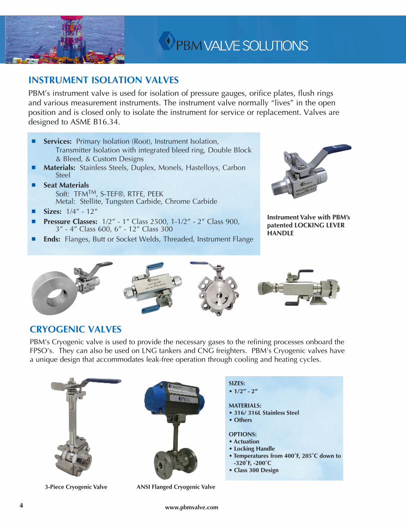
INSTRUMENT ISOLATION VALVESPBM’s instrument valve is used for isolation of pressure gauges, orifice plates, flush rings and various measurement instruments. The instrument valve normally “lives” in the open position and is closed only to isolate the instrument for service or replacement. Valves are designed to ASME B16.34.
cRyOgENIc VALVESPBM’s Cryogenic valve is used to provide the necessary gases to the refining processes onboard the FPSO’s. They can also be used on LNG tankers and CNG freighters. PBM’s Cryogenic valves have a unique design that accommodates leak-free operation through cooling and heating cycles.
n Services: Primary Isolation (Root), Instrument Isolation, Transmitter Isolation with integrated bleed ring, Double Block & Bleed, & Custom Designs
n Materials: Stainless Steels, Duplex, Monels, Hastelloys, Carbon Steel
n SeatMaterials Soft: TFMTM, S-TEF®, RTFE, PEEK Metal: Stellite, Tungsten Carbide, Chrome Carbiden Sizes: 1/4” - 12”n PressureClasses: 1/2” - 1” Class 2500, 1-1/2” - 2” Class 900, 3” - 4” Class 600, 6” - 12” Class 300n Ends: Flanges, Butt or Socket Welds, Threaded, Instrument Flange
SIZES:•1/2”-2”
MATERIALS:•316/316LStainlessSteel•Others
OPTIONS:•Actuation•LockingHandle•Temperaturesfrom400˚F,205˚Cdownto-320˚F,-200˚C•Class300Design
3-PieceCryogenicValve ANSIFlangedCryogenicValve
InstrumentValvewithPBM’spatentedLOCKINGLEVERHANDLE
www.pbmvalve.com
F
E
D
B
A
G
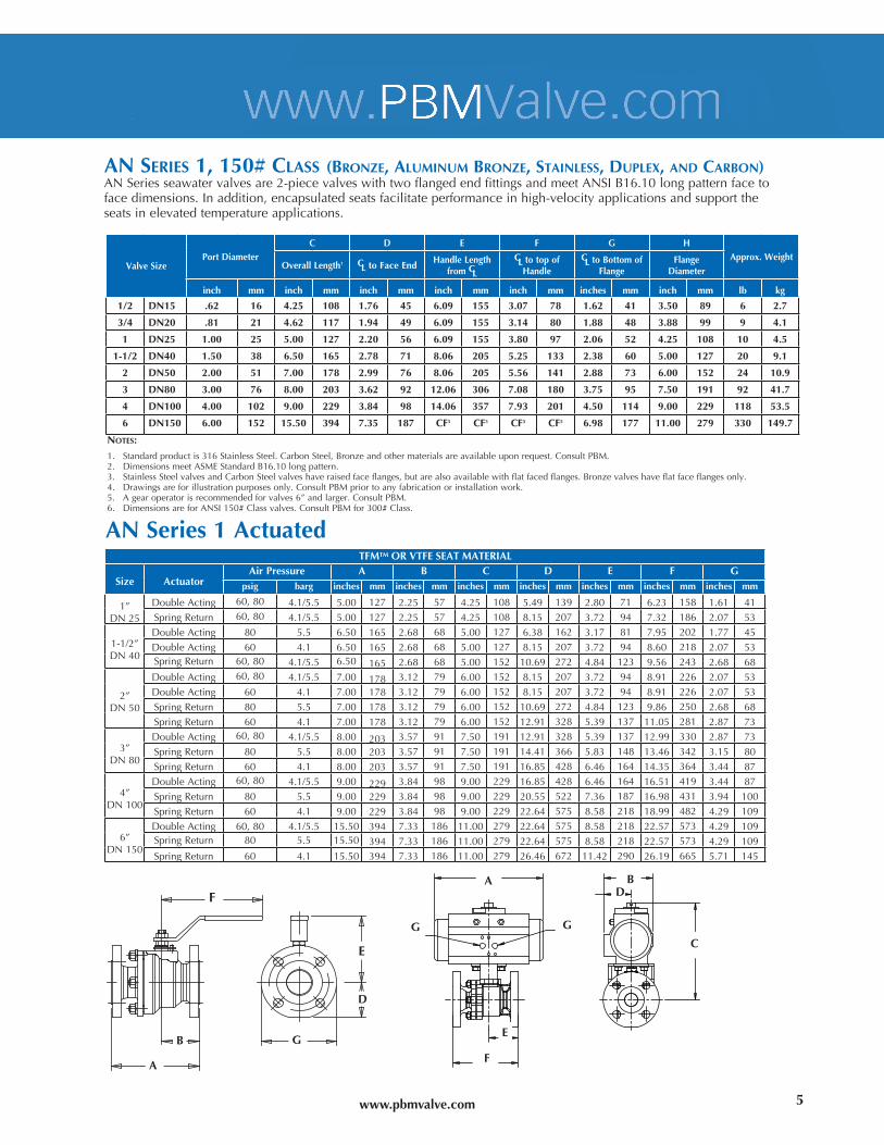
AN SERIES 1, 150# cLASS (bRONzE, ALUMINUM bRONzE, STAINLESS, dUpLEx, ANd cARbON)ANSeriesseawatervalvesare2-piecevalveswithtwoflangedendfittingsandmeetANSIB16.10longpatternfacetofacedimensions.Inaddition,encapsulatedseatsfacilitateperformanceinhigh-velocityapplicationsandsupporttheseatsinelevatedtemperatureapplications.
NOTES:
1. Standardproductis316StainlessSteel.CarbonSteel,Bronzeandothermaterialsareavailableuponrequest.ConsultPBM.2. DimensionsmeetASMEStandardB16.10longpattern.3. StainlessSteelvalvesandCarbonSteelvalveshaveraisedfaceflanges,butarealsoavailablewithflatfacedflanges.Bronzevalveshaveflatfaceflangesonly.4. Drawingsareforillustrationpurposesonly.ConsultPBMpriortoanyfabricationorinstallationwork.5. Agearoperatorisrecommendedforvalves6”andlarger.ConsultPBM.6. DimensionsareforANSI150#Classvalves.ConsultPBMfor300#Class.
ValveSizePortDiameter
C D E F G HApprox.Weight
OverallLength1 CLtoFaceEndHandleLength
fromCL
CLtotopofHandle
CLtoBottomofFlange
FlangeDiameter
inch mm inch mm inch mm inch mm inch mm inches mm inch mm lb kg
1/2 DN15 .62 16 4.25 108 1.76 45 6.09 155 3.07 78 1.62 41 3.50 89 6 2.7
3/4 DN20 .81 21 4.62 117 1.94 49 6.09 155 3.14 80 1.88 48 3.88 99 9 4.1
1 DN25 1.00 25 5.00 127 2.20 56 6.09 155 3.80 97 2.06 52 4.25 108 10 4.5
1-1/2 DN40 1.50 38 6.50 165 2.78 71 8.06 205 5.25 133 2.38 60 5.00 127 20 9.1
2 DN50 2.00 51 7.00 178 2.99 76 8.06 205 5.56 141 2.88 73 6.00 152 24 10.9
3 DN80 3.00 76 8.00 203 3.62 92 12.06 306 7.08 180 3.75 95 7.50 191 92 41.7
4 DN100 4.00 102 9.00 229 3.84 98 14.06 357 7.93 201 4.50 114 9.00 229 118 53.5
6 DN150 6.00 152 15.50 394 7.35 187 CF5 CF5 CF5 CF5 6.98 177 11.00 279 330 149.7
ANSeries1ActuatedTFMTMORVTFESEATMATERIAL
Size ActuatorAirPressure A B C D E F G
psig barg inches mm inches mm inches mm inches mm inches mm inches mm inches mm
1”DN25
DoubleActing 60,80 4.1/5.5 5.00 127 2.25 57 4.25 108 5.49 139 2.80 71 6.23 158 1.61 41SpringReturn 60,80 4.1/5.5 5.00 127 2.25 57 4.25 108 8.15 207 3.72 94 7.32 186 2.07 53
1-1/2”DN40
DoubleActing 80 5.5 6.50 165 2.68 68 5.00 127 6.38 162 3.17 81 7.95 202 1.77 45DoubleActing 60 4.1 6.50 165 2.68 68 5.00 127 8.15 207 3.72 94 8.60 218 2.07 53SpringReturn 60,80 4.1/5.5 6.50 165 2.68 68 5.00 152 10.69 272 4.84 123 9.56 243 2.68 68
2”DN50
DoubleActing 60,80 4.1/5.5 7.00 178 3.12 79 6.00 152 8.15 207 3.72 94 8.91 226 2.07 53DoubleActing 60 4.1 7.00 178 3.12 79 6.00 152 8.15 207 3.72 94 8.91 226 2.07 53SpringReturn 80 5.5 7.00 178 3.12 79 6.00 152 10.69 272 4.84 123 9.86 250 2.68 68SpringReturn 60 4.1 7.00 178 3.12 79 6.00 152 12.91 328 5.39 137 11.05 281 2.87 73
3”DN80
DoubleActing 60,80 4.1/5.5 8.00 203 3.57 91 7.50 191 12.91 328 5.39 137 12.99 330 2.87 73SpringReturn 80 5.5 8.00 203 3.57 91 7.50 191 14.41 366 5.83 148 13.46 342 3.15 80SpringReturn 60 4.1 8.00 203 3.57 91 7.50 191 16.85 428 6.46 164 14.35 364 3.44 87
4”DN100
DoubleActing 60,80 4.1/5.5 9.00 229 3.84 98 9.00 229 16.85 428 6.46 164 16.51 419 3.44 87SpringReturn 80 5.5 9.00 229 3.84 98 9.00 229 20.55 522 7.36 187 16.98 431 3.94 100SpringReturn 60 4.1 9.00 229 3.84 98 9.00 229 22.64 575 8.58 218 18.99 482 4.29 109
6”DN150
DoubleActing 60,80 4.1/5.5 15.50 394 7.33 186 11.00 279 22.64 575 8.58 218 22.57 573 4.29 109SpringReturn 80 5.5 15.50 394 7.33 186 11.00 279 22.64 575 8.58 218 22.57 573 4.29 109SpringReturn 60 4.1 15.50 394 7.33 186 11.00 279 26.46 672 11.42 290 26.19 665 5.71 145
D
E
F
G
A B
CG
5
www.pbmvalve.com
A B
D
C
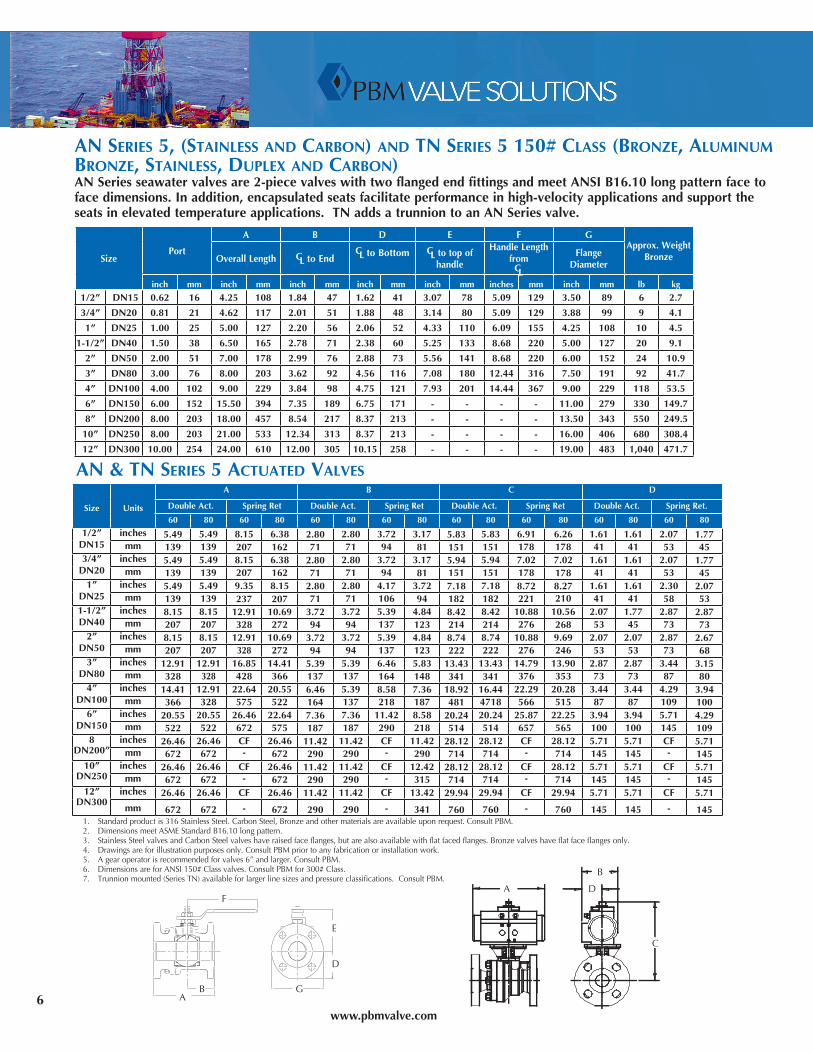
AN SERIES 5, (STAINLESS ANd cARbON) ANd TN SERIES 5 150# cLASS (bRONzE, ALUMINUM bRONzE, STAINLESS, dUpLEx ANd cARbON)ANSeriesseawatervalvesare2-piecevalveswithtwoflangedendfittingsandmeetANSIB16.10longpatternfacetofacedimensions.Inaddition,encapsulatedseatsfacilitateperformanceinhigh-velocityapplicationsandsupporttheseatsinelevatedtemperatureapplications.TNaddsatrunniontoanANSeriesvalve.
SizePort
A B D E F GApprox.Weight
BronzeOverallLength CLtoEndCLtoBottom CLtotopof
handle
HandleLengthfromCL
FlangeDiameter
inch mm inch mm inch mm inch mm inch mm inches mm inch mm lb kg
1/2” DN15 0.62 16 4.25 108 1.84 47 1.62 41 3.07 78 5.09 129 3.50 89 6 2.7
3/4” DN20 0.81 21 4.62 117 2.01 51 1.88 48 3.14 80 5.09 129 3.88 99 9 4.1
1” DN25 1.00 25 5.00 127 2.20 56 2.06 52 4.33 110 6.09 155 4.25 108 10 4.5
1-1/2” DN40 1.50 38 6.50 165 2.78 71 2.38 60 5.25 133 8.68 220 5.00 127 20 9.1
2” DN50 2.00 51 7.00 178 2.99 76 2.88 73 5.56 141 8.68 220 6.00 152 24 10.9
3” DN80 3.00 76 8.00 203 3.62 92 4.56 116 7.08 180 12.44 316 7.50 191 92 41.7
4” DN100 4.00 102 9.00 229 3.84 98 4.75 121 7.93 201 14.44 367 9.00 229 118 53.5
6” DN150 6.00 152 15.50 394 7.35 189 6.75 171 - - - - 11.00 279 330 149.7
8” DN200 8.00 203 18.00 457 8.54 217 8.37 213 - - - - 13.50 343 550 249.5
10” DN250 8.00 203 21.00 533 12.34 313 8.37 213 - - - - 16.00 406 680 308.4
12” DN300 10.00 254 24.00 610 12.00 305 10.15 258 - - - - 19.00 483 1,040 471.7
Size Units
A B C D
DoubleAct. SpringRet DoubleAct. SpringRet DoubleAct. SpringRet DoubleAct. SpringRet.
60 80 60 80 60 80 60 80 60 80 60 80 60 80 60 80
1/2”DN15
inches 5.49 5.49 8.15 6.38 2.80 2.80 3.72 3.17 5.83 5.83 6.91 6.26 1.61 1.61 2.07 1.77mm 139 139 207 162 71 71 94 81 151 151 178 178 41 41 53 45
3/4”DN20
inches 5.49 5.49 8.15 6.38 2.80 2.80 3.72 3.17 5.94 5.94 7.02 7.02 1.61 1.61 2.07 1.77mm 139 139 207 162 71 71 94 81 151 151 178 178 41 41 53 45
1”DN25
inches 5.49 5.49 9.35 8.15 2.80 2.80 4.17 3.72 7.18 7.18 8.72 8.27 1.61 1.61 2.30 2.07mm 139 139 237 207 71 71 106 94 182 182 221 210 41 41 58 53
1-1/2”DN40
inches 8.15 8.15 12.91 10.69 3.72 3.72 5.39 4.84 8.42 8.42 10.88 10.56 2.07 1.77 2.87 2.87mm 207 207 328 272 94 94 137 123 214 214 276 268 53 45 73 73
2”DN50
inches 8.15 8.15 12.91 10.69 3.72 3.72 5.39 4.84 8.74 8.74 10.88 9.69 2.07 2.07 2.87 2.67mm 207 207 328 272 94 94 137 123 222 222 276 246 53 53 73 68
3”DN80
inches 12.91 12.91 16.85 14.41 5.39 5.39 6.46 5.83 13.43 13.43 14.79 13.90 2.87 2.87 3.44 3.15mm 328 328 428 366 137 137 164 148 341 341 376 353 73 73 87 80
4”DN100
inches 14.41 12.91 22.64 20.55 6.46 5.39 8.58 7.36 18.92 16.44 22.29 20.28 3.44 3.44 4.29 3.94mm 366 328 575 522 164 137 218 187 481 4718 566 515 87 87 109 100
6”DN150
inches 20.55 20.55 26.46 22.64 7.36 7.36 11.42 8.58 20.24 20.24 25.87 22.25 3.94 3.94 5.71 4.29mm 522 522 672 575 187 187 290 218 514 514 657 565 100 100 145 109
8DN200”
inches 26.46 26.46 CF 26.46 11.42 11.42 CF 11.42 28.12 28.12 CF 28.12 5.71 5.71 CF 5.71mm 672 672 - 672 290 290 - 290 714 714 - 714 145 145 - 145
10”DN250
inches 26.46 26.46 CF 26.46 11.42 11.42 CF 12.42 28.12 28.12 CF 28.12 5.71 5.71 CF 5.71mm 672 672 - 672 290 290 - 315 714 714 - 714 145 145 - 145
12”DN300
inches 26.46 26.46 CF 26.46 11.42 11.42 CF 13.42 29.94 29.94 CF 29.94 5.71 5.71 CF 5.71
mm 672 672 - 672 290 290 - 341 760 760 - 760 145 145 - 1451. Standardproductis316StainlessSteel.CarbonSteel,Bronzeandothermaterialsareavailableuponrequest.ConsultPBM.2. DimensionsmeetASMEStandardB16.10longpattern.3. StainlessSteelvalvesandCarbonSteelvalveshaveraisedfaceflanges,butarealsoavailablewithflatfacedflanges.Bronzevalveshaveflatfaceflangesonly.4. Drawingsareforillustrationpurposesonly.ConsultPBMpriortoanyfabricationorinstallationwork.5. Agearoperatorisrecommendedforvalves6”andlarger.ConsultPBM.6. DimensionsareforANSI150#Classvalves.ConsultPBMfor300#Class.7. Trunnionmounted(SeriesTN)availableforlargerlinesizesandpressureclassifications.ConsultPBM.
AN & TN SERIES 5 AcTUATEd VALVES
F
E
A
B
D
6 G
www.pbmvalve.com
ValveSize
B C D G E FApproximate
WeightBallPort
Face-to-Face CLtoEnd CLtoBottomorSide HandleLengthfromCL
CLtoTopofHandle
150#FlangeDiam.Q-
S-U-
L-Q-S-U-
L- Q-S-U-
L-Q-S-U-
L-
Size inch mm inch mm inch mm inch mm inch mm inch mm inch mm inches mm inch mm inch mm lb kg lb kg
1/2” DN15 0.62 16 3.12 79 - - 1.56 40 - - 2.50 64 - - 5.06 129 3.03 77 3.50 89 2 0.9 - -
3/4” DN20 0.81 21 3.44 87 - - 1.77 45 - - 2.50 64 - - 5.06 129 3.03 77 2.38 60 2 0.9 - -
1” DN25 1.00 25 3.90 99 6.28 160 1.95 50 3.14 80 2.44 62 3.16 80 6.06 154 3.53 90 4.25 108 4 1.8 10 4.5
1-1/2” DN40 1.50 38 5.36 136 7.00 178 2.68 68 3.50 89 3.25 583 3.50 89 8.06 205 5.05 128 5.00 127 10 4.5 23 10.4
2” DN50 1.94 49 5.71 145 8.40 213 2.86 73 4.20 107 3.25 83 4.20 107 8.06 205 5.42 138 6.00 152 15 6.8 30 13.6
3” DN80 2.75 70 8.62 219 11.87 301 4.31 109 5.93 151 5.12 130 6.00 152 12.06 306 6.71 170 7.50 191 49 22.2 79 35.8
4” DN100 3.50 89 - - 12.91 328 N/A 6.45 164 - - 6.44 164 12.06 306 7.21 183 9.00 229 79 35.8 120 54.4
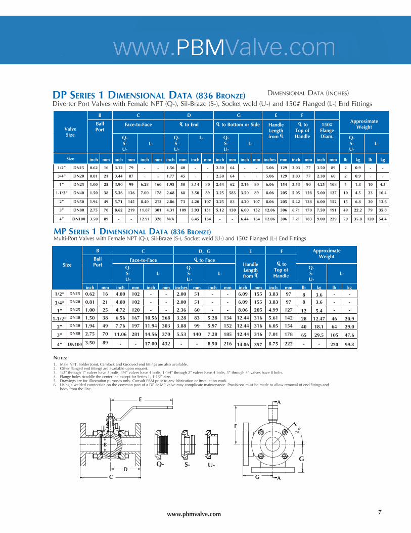
dp SERIES 1 dIMENSIONAL dATA (836 bRONzE)DiverterPortValveswithFemaleNPT(Q-),Sil-Braze(S-),Socketweld(U-)and150#Flanged(L-)EndFittings
NOTES:1. MaleNPT,SolderJoint,CamlockandGroovedendfittingsarealsoavailable.2. Otherflangedendfittingsareavailableuponrequest.3. 1/2”through1”valveshave3bolts,3/4”valveshave4bolts,1-1/4”through2”valveshave4bolts,3”through4”valveshave8bolts.4. FlangeholesstraddlethecenterlineexceptforSeries1,1-1/2”size.5. Drawingsareforillustrationpurposesonly.ConsultPBMpriortoanyfabricationorinstallationwork.6. UsingaweldedconnectiononthecommonportofaDPorMPvalvemaycomplicatemaintenance.Provisionsmustbemadetoallowremovalofendfittingsand
bodyfromtheline.
7
U-S-Q-
Size
B C D,G E F ApproximateWeightBall
PortFace-to-Face CLtoFace
HandleLengthfromCL
CLtoTopofHandle
Q-S-U-
L-Q-S-U-
L-Q-S-U-
L-
inch mm inch mm inch mm inches mm inch mm inch mm inch mm lb kg lb kg1/2” DN15 0.62 16 4.00 102 - - 2.00 51 - - 6.09 155 3.83 97 8 3.6 - -
3/4” DN20 0.81 21 4.00 102 - - 2.00 51 - - 6.09 155 3.83 97 8 3.6 - -
1” DN25 1.00 25 4.72 120 - - 2.36 60 - - 8.06 205 4.99 127 12 5.4 - -
1-1/2” DN40 1.50 38 6.56 167 10.56 268 3.28 83 5.28 134 12.44 316 5.61 142 28 12.47 46 20.9
2” DN50 1.94 49 7.76 197 11.94 303 3.88 99 5.97 152 12.44 316 6.05 154 40 18.1 64 29.0
3” DN80 2.75 70 11.06 281 14.56 370 5.53 140 7.28 185 12.44 316 7.01 178 65 29.5 105 47.6
4” DN100 3.50 89 - - 17.00 432 - - 8.50 216 14.06 357 8.75 222 - - 220 99.8
E
DC A
G
F
A
G
B
DiMensional DaTa (inches)
Mp SERIES 1 dIMENSIONAL dATA (836 bRONzE)Multi-PortValveswithFemaleNPT(Q-),Sil-Braze(S-),Socketweld(U-)and150#Flanged(L-)EndFittings
www.pbmvalve.com
8
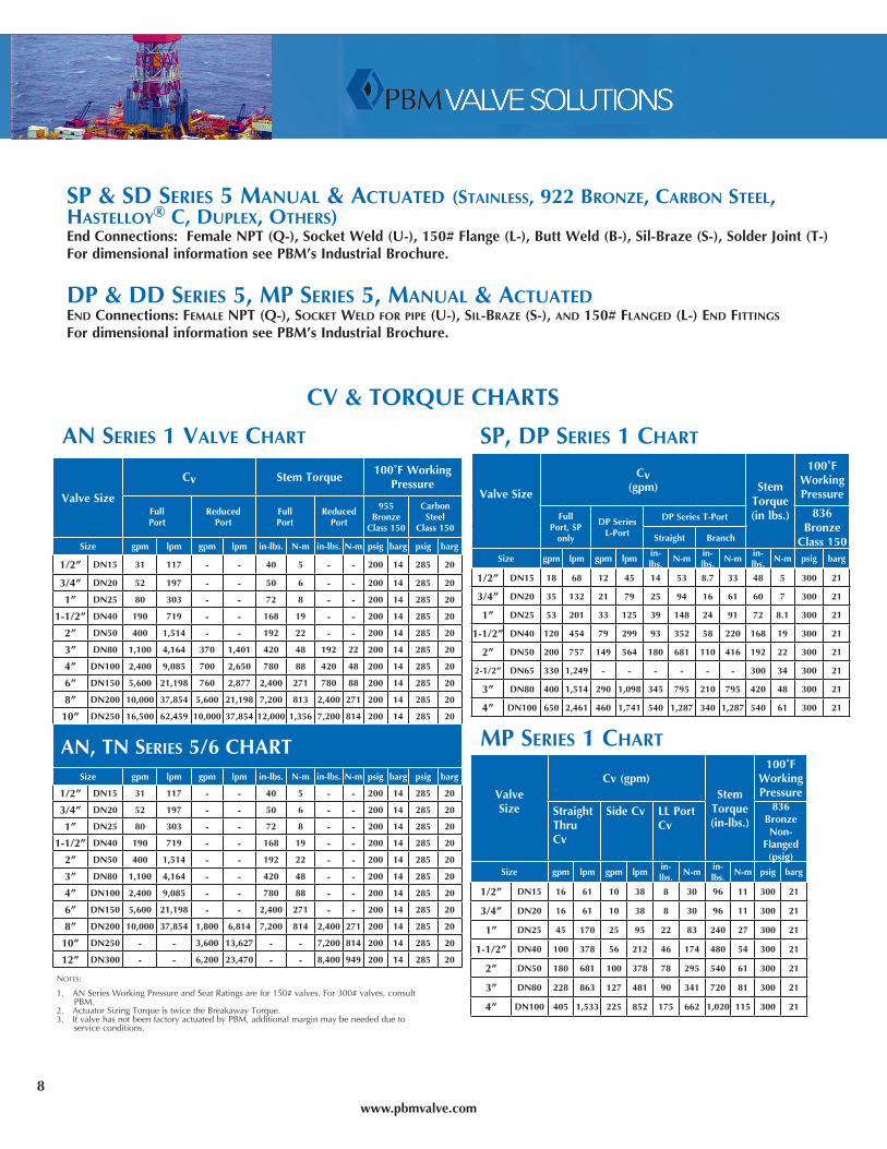
Sp & Sd SERIES 5 MANUAL & AcTUATEd (STAINLESS, 922 bRONzE, cARbON STEEL, hASTELLOy® c, dUpLEx, OThERS)EndConnections:FemaleNPT(Q-),SocketWeld(U-),150#Flange(L-),ButtWeld(B-),Sil-Braze(S-),SolderJoint(T-)FordimensionalinformationseePBM’sIndustrialBrochure.
dp & dd SERIES 5, Mp SERIES 5, MANUAL & AcTUATEd ENd Connections: fEMALE NpT (Q-), SOckET WELd fOR pIpE (U-), SIL-bRAzE (S-), ANd 150# fLANgEd (L-) ENd fITTINgS
FordimensionalinformationseePBM’sIndustrialBrochure.
cV & TORQUE chARTS
Sp, dp SERIES 1 chART
ValveSize
Cv(gpm) Stem
Torque(inlbs.)
100˚FWorkingPressure
FullPort,SP
only
DPSeriesL-Port
DPSeriesT-Port 836Bronze
Class150Straight Branch
Size gpm lpm gpm lpmin-lbs.
N-min-lbs.
N-min-lbs.
N-m psig barg
1/2” DN15 18 68 12 45 14 53 8.7 33 48 5 300 21
3/4” DN20 35 132 21 79 25 94 16 61 60 7 300 21
1” DN25 53 201 33 125 39 148 24 91 72 8.1 300 21
1-1/2” DN40 120 454 79 299 93 352 58 220 168 19 300 21
2” DN50 200 757 149 564 180 681 110 416 192 22 300 21
2-1/2” DN65 330 1,249 - - - - - - 300 34 300 21
3” DN80 400 1,514 290 1,098 345 795 210 795 420 48 300 21
4” DN100 650 2,461 460 1,741 540 1,287 340 1,287 540 61 300 21
Mp SERIES 1 chART
ValveSize
Cv(gpm)Stem
Torque(in-lbs.)
100˚FWorkingPressure
StraightThruCv
SideCv LLPortCv
836BronzeNon-
Flanged(psig)
Size gpm lpm gpm lpmin-lbs.
N-min-lbs.
N-m psig barg
1/2” DN15 16 61 10 38 8 30 96 11 300 21
3/4” DN20 16 61 10 38 8 30 96 11 300 21
1” DN25 45 170 25 95 22 83 240 27 300 21
1-1/2” DN40 100 378 56 212 46 174 480 54 300 21
2” DN50 180 681 100 378 78 295 540 61 300 21
3” DN80 228 863 127 481 90 341 720 81 300 21
4” DN100 405 1,533 225 852 175 662 1,020 115 300 21
AN SERIES 1 VALVE chART
ValveSize
Cv StemTorque100˚FWorking
Pressure
FullPort
ReducedPort
FullPort
ReducedPort
955Bronze
Class150
CarbonSteel
Class150
Size gpm lpm gpm lpm in-lbs. N-m in-lbs. N-m psig barg psig barg
1/2” DN15 31 117 - - 40 5 - - 200 14 285 20
3/4” DN20 52 197 - - 50 6 - - 200 14 285 20
1” DN25 80 303 - - 72 8 - - 200 14 285 20
1-1/2” DN40 190 719 - - 168 19 - - 200 14 285 20
2” DN50 400 1,514 - - 192 22 - - 200 14 285 20
3” DN80 1,100 4,164 370 1,401 420 48 192 22 200 14 285 20
4” DN100 2,400 9,085 700 2,650 780 88 420 48 200 14 285 20
6” DN150 5,600 21,198 760 2,877 2,400 271 780 88 200 14 285 20
8” DN200 10,000 37,854 5,600 21,198 7,200 813 2,400 271 200 14 285 20
10” DN250 16,500 62,459 10,000 37,854 12,000 1,356 7,200 814 200 14 285 20
AN, TN SERIES 5/6 chARTSize gpm lpm gpm lpm in-lbs. N-m in-lbs. N-m psig barg psig barg
1/2” DN15 31 117 - - 40 5 - - 200 14 285 20
3/4” DN20 52 197 - - 50 6 - - 200 14 285 20
1” DN25 80 303 - - 72 8 - - 200 14 285 20
1-1/2” DN40 190 719 - - 168 19 - - 200 14 285 20
2” DN50 400 1,514 - - 192 22 - - 200 14 285 20
3” DN80 1,100 4,164 - - 420 48 - - 200 14 285 20
4” DN100 2,400 9,085 - - 780 88 - - 200 14 285 20
6” DN150 5,600 21,198 - - 2,400 271 - - 200 14 285 20
8” DN200 10,000 37,854 1,800 6,814 7,200 814 2,400 271 200 14 285 20
10” DN250 - - 3,600 13,627 - - 7,200 814 200 14 285 20
12” DN300 - - 6,200 23,470 - - 8,400 949 200 14 285 20
Notes:
1. ANSeriesWorkingPressureandSeatRatingsarefor150#valves.For300#valves,consultPBM.
2. ActuatorSizingTorqueistwicetheBreakawayTorque.3. IfvalvehasnotbeenfactoryactuatedbyPBM,additionalmarginmaybeneededdueto
serviceconditions.
www.pbmvalve.com
bOdy bOLTS304 STAINLESS STEELAlloy304,A193gradeB8,class1bolts/studsandA194,grade8nuts.PBMdoesnotrecommendtheuseofstainlesssteelinasalt-waterenvironment.Stainlessissubjecttopittingandstresscorrosioncrackingwhenincontactwithseawater.Alloy304is18-20%chromium,8-10%nickel,andabalanceofironandtraceelements.
cOppER SILIcON bRONzECopperSiliconBronzeissuppliedtoalloynumbersCu651andCu655.AlloynumberCu655is94.8%copper,0.8%iron,1.5%manganese,0.6%nickel,2.8-3.8%silicon,1.5%zinc,and0.05%lead.AlloynumberCu651is96%copper,0.8%iron,0.7%man-ganese,0.8-2%silicon,1.5%zinc,and0.05%lead.BoltsandstudsaremadetospecificationF468fornon-ferrousbolts.NutsaremadetospecificationF467.
MONEL® Monelbolts(F468)arealloyN.400orN.405nickelcopper,andnuts(F467)arealloyN04400orN04405nickelcopper.Compositionis63-70%nickel,25.5-32.5%copper,2.5%iron,and2%manganese.
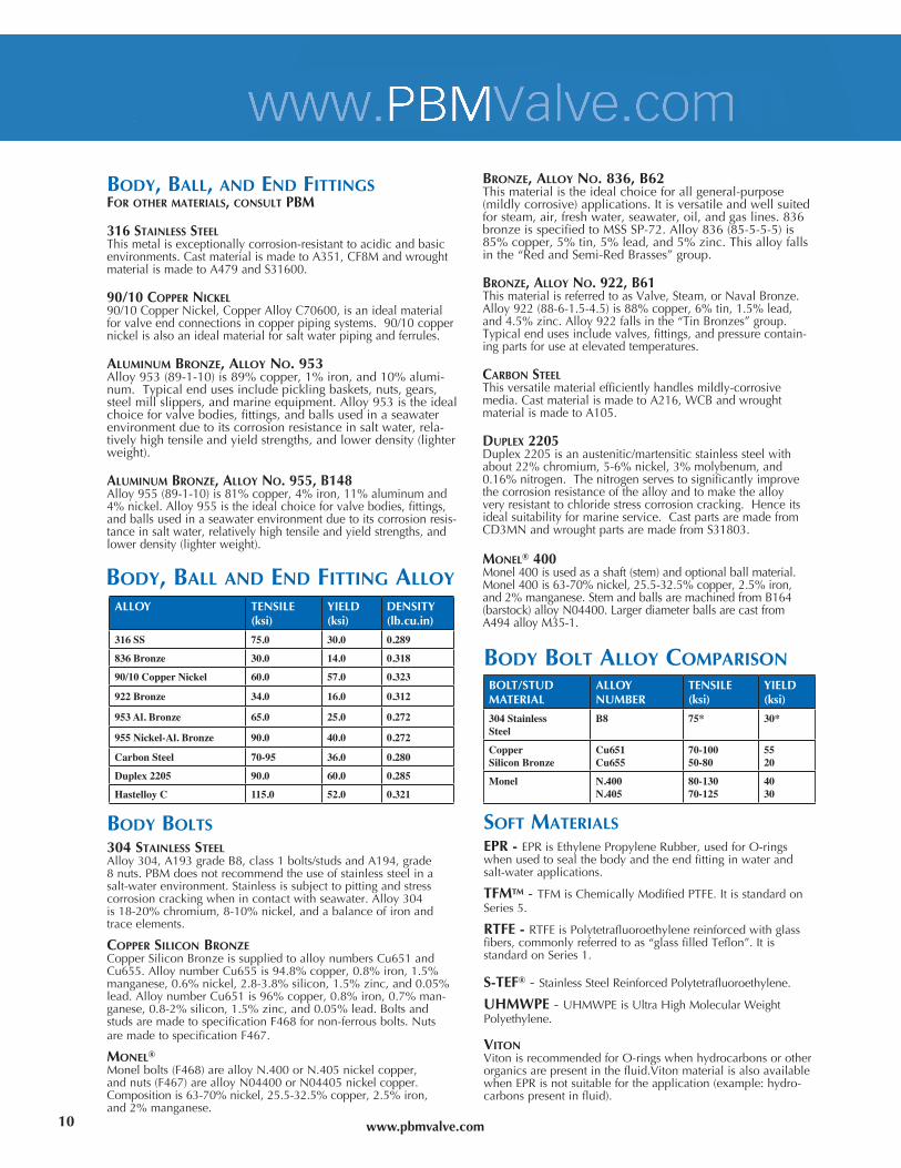
bOdy, bALL, ANd ENd fITTINgSfOR OThER MATERIALS, cONSULT pbM
316 STAINLESS STEELThismetalisexceptionallycorrosion-resistanttoacidicandbasicenvironments.CastmaterialismadetoA351,CF8MandwroughtmaterialismadetoA479andS31600.
90/10 cOppER NIckEL90/10CopperNickel,CopperAlloyC70600,isanidealmaterialforvalveendconnectionsincopperpipingsystems.90/10coppernickelisalsoanidealmaterialforsaltwaterpipingandferrules.
ALUMINUM bRONzE, ALLOy NO. 953 Alloy953(89-1-10)is89%copper,1%iron,and10%alumi-num.Typicalendusesincludepicklingbaskets,nuts,gears,steelmillslippers,andmarineequipment.Alloy953istheidealchoiceforvalvebodies,fittings,andballsusedinaseawaterenvironmentduetoitscorrosionresistanceinsaltwater,rela-tivelyhightensileandyieldstrengths,andlowerdensity(lighterweight).
ALUMINUM bRONzE, ALLOy NO. 955, b148Alloy955(89-1-10)is81%copper,4%iron,11%aluminumand4%nickel.Alloy955istheidealchoiceforvalvebodies,fittings,andballsusedinaseawaterenvironmentduetoitscorrosionresis-tanceinsaltwater,relativelyhightensileandyieldstrengths,andlowerdensity(lighterweight).
bRONzE, ALLOy NO. 836, b62Thismaterialistheidealchoiceforallgeneral-purpose(mildlycorrosive)applications.Itisversatileandwellsuitedforsteam,air,freshwater,seawater,oil,andgaslines.836bronzeisspecifiedtoMSSSP-72.Alloy836(85-5-5-5)is85%copper,5%tin,5%lead,and5%zinc.Thisalloyfallsinthe“RedandSemi-RedBrasses”group.
bRONzE, ALLOy NO. 922, b61ThismaterialisreferredtoasValve,Steam,orNavalBronze.Alloy922(88-6-1.5-4.5)is88%copper,6%tin,1.5%lead,and4.5%zinc.Alloy922fallsinthe“TinBronzes”group.Typicalendusesincludevalves,fittings,andpressurecontain-ingpartsforuseatelevatedtemperatures.
cARbON STEEL Thisversatilematerialefficientlyhandlesmildly-corrosivemedia.CastmaterialismadetoA216,WCBandwroughtmaterialismadetoA105.
dUpLEx 2205Duplex2205isanaustenitic/martensiticstainlesssteelwithabout22%chromium,5-6%nickel,3%molybenum,and0.16%nitrogen.Thenitrogenservestosignificantlyimprovethecorrosionresistanceofthealloyandtomakethealloyveryresistanttochloridestresscorrosioncracking.Henceitsidealsuitabilityformarineservice.CastpartsaremadefromCD3MNandwroughtpartsaremadefromS31803.
MONEL® 400Monel400isusedasashaft(stem)andoptionalballmaterial.Monel400is63-70%nickel,25.5-32.5%copper,2.5%iron,and2%manganese.StemandballsaremachinedfromB164(barstock)alloyN04400.LargerdiameterballsarecastfromA494alloyM35-1.
ALLOY TENSILE(ksi)
YIELD(ksi)
DENSITY(lb.cu.in)
316 SS 75.0 30.0 0.289
836 Bronze 30.0 14.0 0.318
90/10 Copper Nickel 60.0 57.0 0.323
922 Bronze 34.0 16.0 0.312
953 Al. Bronze 65.0 25.0 0.272
955 Nickel-Al. Bronze 90.0 40.0 0.272
Carbon Steel 70-95 36.0 0.280
Duplex 2205 90.0 60.0 0.285
Hastelloy C 115.0 52.0 0.321
BOLT/STUDMATERIAL
ALLOYNUMBER
TENSILE(ksi)
YIELD(ksi)
304 StainlessSteel
B8 75* 30*
Copper Silicon Bronze
Cu651Cu655
70-10050-80
5520
Monel N.400N.405
80-13070-125
4030
bOdy, bALL ANd ENd fITTINg ALLOy
bOdy bOLT ALLOy cOMpARISON
SOfT MATERIALSEPR-EPRisEthylenePropyleneRubber,usedforO-ringswhenusedtosealthebodyandtheendfittinginwaterandsalt-waterapplications.
TfMTM - TFMisChemicallyModifiedPTFE.ItisstandardonSeries5.
RTfE - RTFEisPolytetrafluoroethylenereinforcedwithglassfibers,commonlyreferredtoas“glassfilledTeflon”.ItisstandardonSeries1.
S-TEf® - StainlessSteelReinforcedPolytetrafluoroethylene.
UhMWpE - UHMWPEisUltraHighMolecularWeightPolyethylene.
VITONVitonisrecommendedforO-ringswhenhydrocarbonsorotherorganicsarepresentinthefluid.VitonmaterialisalsoavailablewhenEPRisnotsuitablefortheapplication(example:hydro-carbonspresentinfluid).
10
www.pbmvalve.com
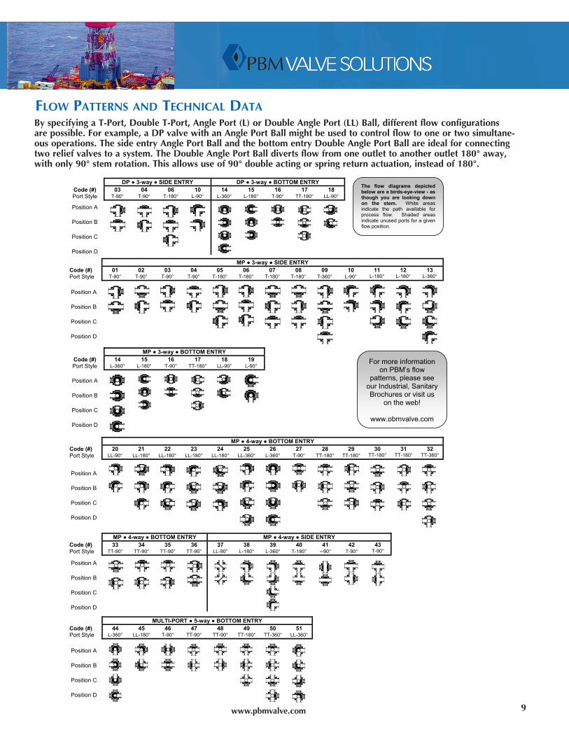
ByspecifyingaT-Port,DoubleT-Port,AnglePort(L)orDoubleAnglePort(LL)Ball,differentflowconfigurationsarepossible.Forexample,aDPvalvewithanAnglePortBallmightbeusedtocontrolflowtooneortwosimultane-ousoperations.ThesideentryAnglePortBallandthebottomentryDoubleAnglePortBallareidealforconnectingtworeliefvalvestoasystem.TheDoubleAnglePortBalldivertsflowfromoneoutlettoanotheroutlet180°away,withonly90°stemrotation.Thisallowsuseof90°doubleactingorspringreturnactuation,insteadof180°.
fLOW pATTERNS ANd TEchNIcAL dATA
FLOW
PATTER
NS
For more information on PBM’s flow
patterns, please see our Industrial, Sanitary Brochures or visit us
on the web!
www.pbmvalve.com
DP ● 3-way ● SIDE ENTRY DP ● 3-way ● BOTTOM ENTRY Code (#) 03 04 06 10 14 15 16 17 18 Port Style T-90° T-90° T-180° L-90° L-360° L-180° T-90° TT-180° LL-90°
Position A
Position B
Position C
Position D
MP ● 3-way ● SIDE ENTRY Code (#) 01 02 03 04 05 06 07 08 09 10 11 12 13 Port Style T-90° T-90° T-90° T-90° T-180° T-180° T-180° T-180° T-360° L-90° L-180° L-180° L-360°
Position A
Position B
Position C
Position D
MP ● 3-way ● BOTTOM ENTRY Code (#) 14 15 16 17 18 19 Port Style L-360° L-180° T-90° TT-180° LL-90° L-90°
Position A
Position B
Position C
Position D
MP ● 4-way ● BOTTOM ENTRY Code (#) 20 21 22 23 24 25 26 27 28 29 30 31 32 Port Style LL-90° LL-180° LL-180° LL-180° LL-180° LL-360° L-360° T-90° TT-180° TT-180° TT-180° TT-180° TT-360°
Position A
Position B
Position C
Position D
MP ● 4-way ● BOTTOM ENTRY MP ● 4-way ● SIDE ENTRY Code (#) 33 34 35 36 37 38 39 40 41 42 43 Port Style TT-90° TT-90° TT-90° TT-90° LL-90° L-180° L-360° T-180° ─90° T-90° T-90°
Position A
Position B
Position C
Position D
MULTI-PORT ● 5-way ● BOTTOM ENTRY Code (#) 44 45 46 47 48 49 50 51 Port Style L-360° LL-180° T-90° TT-90° TT-90° TT-180° TT-360° LL-360°
Position A
Position B
Position C
Position D
The flow diagrams depicted below are a birds-eye-view - as though you are looking down on the stem. White areas indicate the path available for process flow. Shaded areas indicate unused ports for a given flow position.
9
www.pbmvalve.com 11
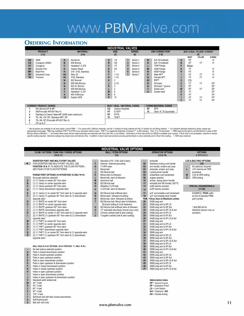
ORdERINg INfORMATION
INDUSTRIAL VALVES
PRODUCT (1-2)
MATERIAL2
(3-4) SIZE (5)
SERIES (6)
END CONNECTION3 (7-8)
SEAT & SEAL / FILLERS / O-RINGS4 (9)
SEAT FILLER O-RING
AN ANSI A- Aluminum A 1/4 1 Series 1 B- Sch 40 buttweld A RT VI CN Cryogenic (ANSI) B- 836 Bronze B 3/8 3 Series 3 D- Sch 10 buttweld B RT VT VI CP Cryogenic C- Hastelloy® C-276 C 1/2 4 Series 4 L- 150# Flange F Metal DP Diverter Port E- Carbon Steel6 D 3/4 5 Series 5 M- 300# Flange G TF VI MP Multi-Port H- 316 / 316L Stainless E 1 6 Series 6 N- 600# Flange H HT VI SP Industrial 2-way HC Alloy 20 F 1-1/4 7 Series 7 P- Male NPT I HT VT VI TN Trunnion HL 316L Stainless G 1-1/2 Q- Female NPT J TF VT VI
N- 922 Bronze5 H 2 Q1 BSPT Q CG R- 955 NiAl-Bronze J 2-1/2 R- Sil-braze U VT VT EP S- 953 Al- Bronze K 3 S- Sil-braze 1 groove V RT EP X- 958 NiAl-Bronze L 4 T- Solder joint W RT VT EP
Y- Hastelloy® C-22® M 6 U- Socket weld Z TF EP 9- 954 Al-Bronze N 8 0 HT EP 22 Duplex 2205 P 10 1 HT VT EP 2 TF VT EP CURRENT PRODUCT SERIES SEAT / SEAL / MATERIAL CODES O-RING MATERIAL CODES
1 AN, Bronze DP & MP CG Carbon-Graphite EP EPR 3 AN(Fire-safe API-607 Rev 4) HT S-TEF® VI Viton “A” 75 Durometer 4 Stainless & Carbon Steel MP (300# class maximum) RT RTFE 5 TN, AN, CN, DP, Stainless MP8, SP TF TFM™ 6 TN, AN, SP (Fire-safe API-607 Rev 4) 7 CP up to 2”
1 - Not all options are available on all valve styles; consult PBM. 2 - For valves with 2 different materials, use the 1st position for body material and the 2nd position for end fitting material. 4 - For standard seat/seal material by series, please see appropriate pricing page. PBM may substitute TFM™ for RTFE at our discretion without notice. TFM™ is a registered trademark of Dyneon™ - a 3M Company. Viton “A” is 75 Durometer. 5 - PBM reserves the right to use 922 Bronze in place of 836 Bronze without notification. 6 - All Carbon Steel valves will be coated internally and externally with Rust Veto 342, a rust inhibitor. Information on Rust Veto and/or an MSDS is available upon request. If Rust Veto is not acceptable, customer to advise specific coating required. Alternate coatings may impact price and delivery time. In addition, Carbon steel cast products are also painted (black in color) externally prior to Rust Veto coating. . 8 -150# class maximum
INDUSTRIAL VALVE OPTIONS
FLOW PATTERN / TANK PAD / PURGE OPTIONS (10 & 11)
BALL / STEM OPTIONS (12)
OPERATOR OPTIONS (13 & 14)
OPTIONS & SPECIALS
DIVERTER PORT AND MULTI-PORT VALVES - Standard (316 / 316L ball & stem) - - w/handle LOX & BOLTING OPTIONS FOR DIVERTER AND MULTI-PORT VALVES, USE F Internal / external grounding 00 Stainless locking oval handle (16) POSITION 10 & 11 TO INDICATE THE FLOW PATTERN - G 17-4PH stem 02 w/o handle, w/stem actr prep - No option(s) required SEE PAGE 8 FOR FLOW PATTERNS I Monel ball 03 w/handle, w/stem actr prep L LOX cleaning per PBM
J 932 Bronze ball 04 Locking lever handle procedure PURGE PORT OPTIONS (POSITION 10 ONLY) K Monel stem & followers 05 w/stainless oval handwheel M LOX & CRN bolting - No purge option(s) selected1 L Monel ball, stem & followers 08 w/gear operator Z CRN bolting A (1) ½” clamp on center 90° from stem M Aluminum ball 10 w/man. spring return handle B (1) ½” clamp on center opposite stem N 922 Bronze ball 11 w/fusible link SR handle (165°F) C (1) ½” clamp upstream 90° from stem O Hastelloy C-276 ball 13 w/N4 electric actuator
D (1) ½” clamp downstream opposite stem P C-276 ball, stem & followers 14 w/XP electric actuator SPECIAL ENGINEERING #
(17-20)
E (2) ½” clamp (1) on center 90° from stem & (1) opposite stem Q 922 Bronze ball w/Monel stem 17 w/4” ext lockable oval handwheel EXAMPLE: PXXX suffix F (2) ½” clamp (1) upstream 90° from stem & (1) downstream R Monel stem, followers & bolting 18 w/4” ext lockable lever handle at end of standard PBM opposite stem S Monel ball, stem, followers & bolting PBM, 110vac Asco & Westlock combo part number
G (1) ½” BWTE on center 90° from stem T 922 Bronze ball, Monel stem & followers, 20 DA80 psig actr H (1) ½” BWTE on center opposite stem Sil-braze bolting & CuSi fasteners 21 DA80 psig actr & GP LS I (1) ½” BWTE upstream 90° from stem U 922 Bronze ball w/Monel stem & followers 22 DA80 psig actr & GP Sol 3 Add $95 list for J (1) ½” BWTE downstream opposite stem V 12” extended stem/body bonnet (cryo only) 23 DA80 psig actr & GP LS & Sol Westlock beacon only on K (2) ½” BWTE on center (1) 90° from stem & (1) opposite stem 1 Chrome carbide (ball & seat coating) 24 DA80 psig actr & XP LS actuators L (2) ½” BWTE (1) upstream 90° from stem & (1) downstream 2 Tungsten carbide (ball & seat coating) 25 DA80 psig actr & XP Sol opposite stem 26 DA80 psig actr & XP LS & Sol
M (1) ¼” FNPT on center 90° from stem 27 DA60 psig actr N (1) ¼” FNPT on center opposite stem 31 DA60 psig actr & XP LS
O (1) ¼” FNPT upstream 90° from stem 32 DA60 psig actr & XP Sol P (1) ¼” FNPT downstream opposite stem 33 DA60 psig actr & XP LS & Sol Q (2) ¼” FNPT (1) on center 90° from stem & (1) opposite stem 34 SR80 psig actr R (2) ¼” FNPT (1) upstream 90° from stem & (1) downstream 35 SR80 psig actr & GP LS opposite stem 36 SR80 psig actr & GP Sol
37 SR80 psig actr & GP LS & Sol 38 SR80 psig actr & XP LS
BALL HOLE & FLAT OPTIONS ( POSITION 11 ONLY ) 39 SR80 psig actr & XP Sol - No ball options selected position 40 SR80 psig actr & XP LS & Sol A Flats in closed downstream position 41 SR60 psig actr B Flats in closed upstream position 42 SR60 psig actr & GP LS C Flats in open upstream position 43 SR60 psig actr & GP Sol D Flats in open downstream position 44 SR60 psig actr & GP LS & Sol E Flats in open upstream & downstream position 45 SR60 psig actr & XP LS F Holes in closed downstream position 46 SR60 psig actr & XP Sol G Holes in closed upstream position 47 SR60 psig actr & XP LS & Sol H Holes in open upstream position I Holes in open downstream position J Holes in open upstream & downstream position V Standard width slotted ball Abbreviation Index W 30° V-ball GP = General Purpose X 45° V-ball XP = Explosion Proof Y 60° V-ball LS = Limit Switch Z 90° V-ball Sol = Solenoid - N/C 1 120° V-ball DA = Double Acting 7 Self-flush ball with flats closed downstream 8 Self-flushing ball 9 Ball with vent hole
LT-2D 6/13
To find your local PBM representatiive or for more information about PBM valves, visitwww.pbmvalve.com or
call us at 1-800-967-4PBM.
www.PBMValve.comPBM,Inc.•1070SandyHillRoad,Irwin,PA15642
Phone:800.967.4PBM•724.863.0550•Fax:724.864.9255E-mail:[email protected]
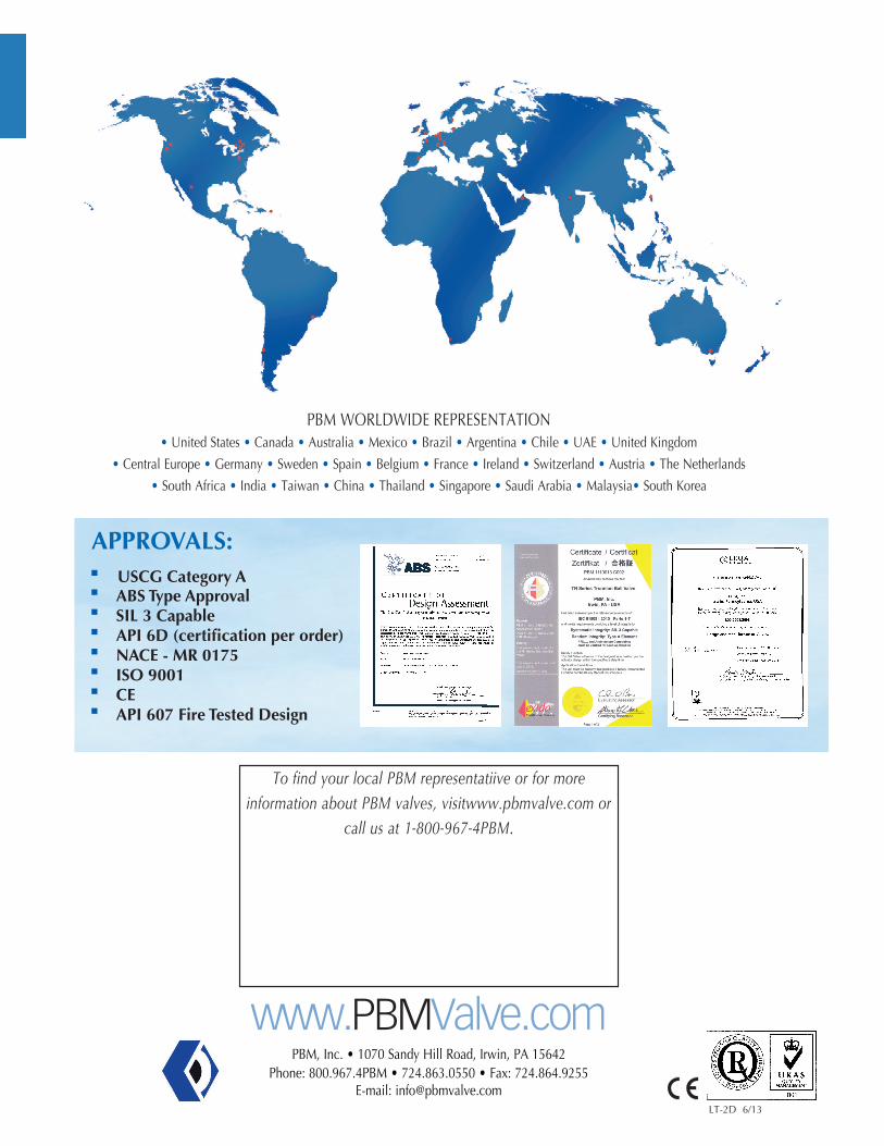
PBMWORLDWIDEREPRESENTATION•UnitedStates•Canada•Australia•Mexico•Brazil•Argentina•Chile•UAE•UnitedKingdom
•CentralEurope•Germany•Sweden•Spain•Belgium•France•Ireland•Switzerland•Austria•TheNetherlands
•SouthAfrica•India•Taiwan•China•Thailand•Singapore•SaudiArabia•Malaysia•SouthKorea
APPROVALS:n USCGCategoryAn ABSTypeApprovaln SIL3Capablen API6D(certificationperorder)n NACE-MR0175n ISO9001n CEn API607FireTestedDesign