Embed Size (px)
Citation preview

MARINE INERGEN 150-BAR SYSTEMS Component Sheet Library
One Stanton Street / Marinette, WI 54143-2542, USA / +1-715-735-7411 / www.ansul.comCopyright © 2015 Tyco Fire Products LP. / All rights reserved. / Form No. PN426313-01 Component Sheets


Form No. Pages
I. ComPoNeNts 1-1 – 1-51
Parts List for ansuL Marine inerGen systeMs 1-1 – 1-4
150-Bar CV-98 VaLVe/CyLinder shiPPinG asseMBLy f-98086-3 1-5
fLexiBLe disCharGe Bend f-98107-2 1-6
LeVer reLease aCtuator f-98092-4 1-7
ConneCtinG Link f-98105-2 1-8
BLank PaGe – – – 1-9
ManuaL PuLL Box f-98093-2 1-10a/b
CoMBination LatCh and Break GLass PuLL Box f-98094-2 1-11
enCLosed douBLe CaBLe PuLL Box f-99103-2 1-11.1
CaBLe with swaGed end fittinG f-98095-2 1-12a/b
Corner PuLLey f-98096-2 1-13
duaL/triPLe ControL Boxes f-98097-2 1-14
reMote CaBLe PuLL equaLizer f-98098-2 1-15
Marine aCtuation station – two-steP f-98101-2 1-16a/b
Marine aCtuation station – one-steP f-98102-2 1-17a/b
extended distanCe Marine aCtuation Method – two-steP f-2005053-2 1-17.1
seLeCtor/isoLation VaLVe PneuMatiC aCtuation f-2010259-1 1-17.2
PiLot VaLVe aCtuation adaPtor f-98099-3 1-18
stainLess steeL aCtuation hose f-98111-2 1-19
1/4 in. Pressure BLeeder PLuG and 1/4 in. Vent fittinG f-98106-2 1-20
BLank PaGe – – – 1-21
BLank PaGe – – – 1-22
header Vent PLuG f-98109-2 1-23
ManifoLd reLief VaLVe f-98110-2 1-24
tiMe deLay asseMBLy f-98104-2 1-25
CheCk VaLVes – threaded f-98108-2 1-26a/b
CheCk VaLVes – fLanGed f-98128-2 1-27a/b
GLoBe VaLVes and ControLs f-98087-2 1-28a/b
seLeCtor VaLVes f-98088-3 1-29a/b
Pressure oPerated staCkaBLe aCtuator f-2001245-2 1-30
BLank PaGe – – – 1-31a
sinGLe MatinG fLanGes f-99065-2 1-32
BLank PaGe – – – 1-33
Pressure reduCer/union f-98112-3 1-34
Pressure reduCer/niPPLe f-98113-3 1-35

Form No. Pages I. ComPoNeNts (Continued) BLank PaGe – – – 1-33
Pressure reduCer/union f-98112-3 1-34
Pressure reduCer/niPPLe f-98113-3 1-35
fLanGed Pressure reduCer f-99067-3 1-36a/b
orifiCe PLate f-99068-3 1-37
360° disCharGe nozzLe f-98114-3 1-38
180° disCharGe nozzLe f-98115-3 1-39
Pressure-oPerated siren f-2012070 1-40
Pressure switCh – 3Pdt f-2012058 1-41
Pressure switCh – dPdt – exPLosion Proof f-98118-2 1-42
BLank PaGe – – – 1-43
Pressure triP f-98120-2 1-44
CyLinder BraCketinG f-98116-2 1-45a/b
Pressure test asseMBLy f-98121-2 1-46
oPeratinG instruCtions – PuLL CaBLe oPeration f-98127-2 1-47
warninG PLate – inside rooM with aLarM f-98125-2 1-48
warninG PLate – outside rooM without aLarM f-98126-2 1-49
naMePLate – Main f-98123-2 1-50
naMePLate – reserVe f-98124-2 1-51
SECTION IU.S.C.G. APPROVAL NO. 162.162/1/0 REV. 4
UL EX-4510 7-14-14 Page 1-1
Components
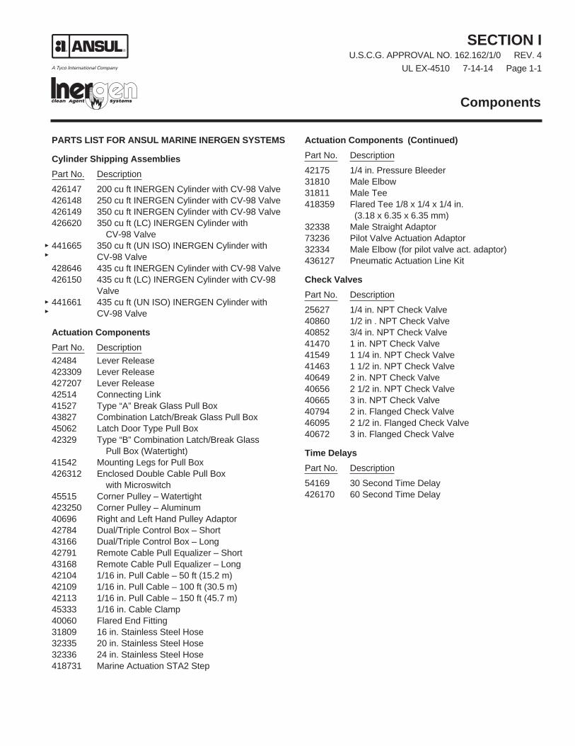
ParTS LIST fOr aNSuL MarINE INErGEN SySTEMS
Cylinder Shipping assembliesPart No. Description426147 200 cu ft INERGEN Cylinder with CV-98 Valve426148 250 cu ft INERGEN Cylinder with CV-98 Valve426149 350 cu ft INERGEN Cylinder with CV-98 Valve426620 350 cu ft (LC) INERGEN Cylinder with
CV-98 Valve441665 350 cu ft (UN ISO) INERGEN Cylinder with
CV-98 Valve428646 435 cu ft INERGEN Cylinder with CV-98 Valve426150 435 cu ft (LC) INERGEN Cylinder with CV-98
Valve441661 435 cu ft (UN ISO) INERGEN Cylinder with
CV-98 Valve
actuation ComponentsPart No. Description42484 Lever Release423309 Lever Release427207 Lever Release42514 Connecting Link41527 Type “A” Break Glass Pull Box43827 Combination Latch/Break Glass Pull Box45062 Latch Door Type Pull Box42329 Type “B” Combination Latch/Break Glass Pull Box (Watertight)41542 Mounting Legs for Pull Box426312 Enclosed Double Cable Pull Box with Microswitch45515 Corner Pulley – Watertight423250 Corner Pulley – Aluminum40696 Right and Left Hand Pulley Adaptor42784 Dual/Triple Control Box – Short43166 Dual/Triple Control Box – Long42791 Remote Cable Pull Equalizer – Short43168 Remote Cable Pull Equalizer – Long42104 1/16 in. Pull Cable – 50 ft (15.2 m)42109 1/16 in. Pull Cable – 100 ft (30.5 m)42113 1/16 in. Pull Cable – 150 ft (45.7 m)45333 1/16 in. Cable Clamp40060 Flared End Fitting31809 16 in. Stainless Steel Hose32335 20 in. Stainless Steel Hose32336 24 in. Stainless Steel Hose418731 Marine Actuation STA2 Step
actuation Components (Continued)Part No. Description42175 1/4 in. Pressure Bleeder31810 Male Elbow31811 Male Tee418359 Flared Tee 1/8 x 1/4 x 1/4 in. (3.18 x 6.35 x 6.35 mm)32338 Male Straight Adaptor73236 Pilot Valve Actuation Adaptor32334 Male Elbow (for pilot valve act. adaptor)436127 Pneumatic Actuation Line Kit
Check ValvesPart No. Description25627 1/4 in. NPT Check Valve40860 1/2 in . NPT Check Valve40852 3/4 in. NPT Check Valve41470 1 in. NPT Check Valve41549 1 1/4 in. NPT Check Valve41463 1 1/2 in. NPT Check Valve40649 2 in. NPT Check Valve40656 2 1/2 in. NPT Check Valve40665 3 in. NPT Check Valve40794 2 in. Flanged Check Valve46095 2 1/2 in. Flanged Check Valve40672 3 in. Flanged Check Valve
Time DelaysPart No. Description54169 30 Second Time Delay426170 60 Second Time Delay

Components
SECTION IU.S.C.G. APPROVAL NO. 162.162/1/0 REV. 3UL EX-4510 4-16-12 Page 1-2
ParTS LIST fOr aNSuL MarINE INErGEN SySTEMS (Continued)
Globe Valves and Controls (for Pull Cable or Manual Operation)Part No. Description41451 1/2 in. Globe Valve40276 1/2 in. Sector40238 1/2 in. Lever, Normally Closed40248 1/2 in. Lever, Normally Open41102 3/4 in. Globe Valve40279 3/4 in. Sector40239 3/4 in. Lever, Normally Closed40267 3/4 in. Lever, Normally Open
Selector ValvesPart No. Description427185 1 in. Selector Valve – Threaded427150 2 in. Selector Valve – Threaded57433 3 in. Selector Valve – Flanged57445 4 in. Selector Valve – Flanged
actuation Components for Selector ValvesPart No. Description427207 Lever Release428566 Pressure-Operated Stackable Actuator
remote Pressure actuation ComponentsPart No. Description418731 Marine Actuation Station – 2 Step67686 Marine Actuation Station – 1 Step7012 LT-20-L Nitrogen Cartridge52056 1/2 in. 14 NPT Pipe Plug
360° Discharge NozzlesPart No. Description417908 1/4 in. NPT Nozzle417723 3/8 in. NPT Nozzle417362 1/2 in. NPT Nozzle417363 3/4 in. NPT Nozzle417364 1 in. NPT Nozzle417365 1 1/4 in. NPT Nozzle417366 1 1/2 in. NPT Nozzle426155 2 in. NPT Nozzle426156 2 1/2 in. NPT Nozzle426137 3 in. NPT Nozzle
180° Discharge NozzlesPart No. Description426138 1/4 in. NPT Nozzle426139 3/8 in. NPT Nozzle426140 1/2 in. NPT Nozzle426141 3/4 in. NPT Nozzle426142 1 in. NPT Nozzle426143 1 1/4 in. NPT Nozzle426157 1 1/2 in. NPT Nozzle426144 2 in. NPT Nozzle426145 2 1/2 in. NPT Nozzle426146 3 in. NPT Nozzle
Components

SECTION IU.S.C.G. APPROVAL NO. 162.162/1/0 REV. 1
UL EX-4510 12-18-09 Page 1-3
Components
ParTS LIST fOr aNSuL MarINE INErGEN SySTEMS (Continued)
Nameplates Note: System operating instruction charts are provided to
suit each individual system and have part numbers unique to each system. A prefix of “S-” will identify instruction chart part numbers.
Part No. Description41942 Nameplate – Main41943 Nameplate – Reserve416265 Warning Plate – Inside Room with Alarm416266 Warning Plate – Outside Room without Alarm41915 Operating Instructions – Pull Cable Actuation41925 Alarm Warning Plate41927 Entrance Warning Plate41908 Nameplate (Specify)432150 Cylinder Actuation Instruction Plate432151 Selector Valve Actuation Instruction Plate
Cylinder Bracketing ComponentsPart No. Description45120 200 cu ft Cylinder Strap45244 200 cu ft Cylinder Channel with Nuts and Bolts45121 250 cu ft Cylinder Strap45261 250 cu ft Cylinder Channel with Nuts and Bolts45122 350 cu ft Cylinder Strap45245 350 cu ft Cylinder Channel with Nuts and Bolts427704 435 cu ft Cylinder Strap427705 435 cu ft Cylinder Channel with Nuts and Bolts79638 Back Frame Assembly – 2 Cylinder79639 Back Frame Assembly – 3 Cylinder79640 Back Frame Assembly – 4 Cylinder79641 Back Frame Assembly – 5 Cylinder79642 Back Frame Assembly – 6 Cylinder73257 Upright73553 Single Row or Back-to-Back Row Bracket Foot
– Left Side73554 Single Row or Back-to-Back Row Bracket Foot
– Right Side73555 Double Row Bracket Foot – Left Side73556 Double Row Bracket Foot – Right Side418508 Center Upright Foot79413 Connector73250 10.5 in. Carriage Bolt with Nut73251 11 in. Carriage Bolt with Nut73252 12.5 in. Carriage Bolt with Nut418502 13 in. Carriage Bolt with Nut73253 21 in. Carriage Bolt with Nut73254 22 in. Carriage Bolt with Nut73255 26 in. Carriage Bolt with Nut418503 27 in. Carriage Bolt with Nut73091 Cylinder Clamp – 2 Cylinders73092 Cylinder Clamp – 3 Cylinders71683 Weigh Rail Support – Single Row71682 Weigh Rail Support – Double Row71684 Weigh Rail Support – Back-to-Back Rows423027 Bracket Upright – Weigh Rail Support Back-to-
Back Double Row

Components
SECTION IU.S.C.G. APPROVAL NO. 162.162/1/0 REV. 3UL EX-4510 4-16-12 Page 1-4
ParTS LIST fOr aNSuL MarINE INErGEN SySTEMS (Continued)
Miscellaneous System ComponentsPart No. Description437900 Pressure Switch – 3PDT43241 Pressure Switch DPST-EXP-Proof05156 Pressure Trip423923 Pressure Test Assembly437616 Pressure-Operated Siren426823 2 1/2 in. Threaded Flanged Pressure Reducer426824 3 in. Threaded Flanged Pressure Reducer426825 4 in. Threaded Flanged Pressure Reducer426847 2 1/2 in. Slip-on Flanged Pressure Reducer426848 3 in. Slip-on Flanged Pressure Reducer426849 4 in. Slip-on Flanged Pressure Reducer426853 2 1/2 in. Weld Neck Flanged Pressure Reducer426854 3 in. Weld Neck Flanged Pressure Reducer426855 4 in. Weld Neck Flanged Pressure Reducer417057 2 1/2 in. NPT Pressure Reducer/Nipple417058 3 in. NPT Pressure Reducer/Nipple416677 1/2 in. NPT Pressure Reducer/Union416678 3/4 in. NPT Pressure Reducer/Union416679 1 in. NPT Pressure Reducer/Union416680 1 1/4 in. NPT Pressure Reducer/Union416681 1 1/2 in. NPT Pressure Reducer/Union416682 2 in. NPT Pressure Reducer/Union418095 1/2 in. Replacement Orifice Plate418096 3/4 in. Replacement Orifice Plate418097 1 in. Replacement Orifice Plate418098 1 1/4 in. Replacement Orifice Plate418099 1 1/2 in. Replacement Orifice Plate418100 2 in. Replacement Orifice Plate426984 2 1/2 in. Replacement Orifice Plate426985 3 in. Replacement Orifice Plate426986 4 in. Replacement Orifice Plate426856 2 1/2 in. Threaded Single Mating Flange426857 3 in. Threaded Single Mating Flange426858 4 in. Threaded Single Mating Flange426859 2 1/2 in. Slip-on Single Mating Flange426860 3 in. Slip-on Single Mating Flange426861 4 in. Slip-on Single Mating Flange426862 2 1/2 in. Weld Neck Single Mating Flange426863 3 in. Weld Neck Single Mating Flange426864 4 in. Weld Neck Single Mating Flange
Miscellaneous System Components (Continued)Part No. Description418378 1/2 in. Manifold Relief Valve40309 Vent Plug427082 Flexible Discharge Bend437919 Gasket42430 Gasket (for previous adaptor design)426028 Bleed Down Device42411 Plug for Actuation Port423923 CV-98 Pressure Tester

System ComponentsU.S.C.G. APPROVAL NO. 162.162/1/0 REV. 4
UL EX-4510 7-14-14 Page 1-5a
150-Bar CV-98 Valve / Cylinder Shipping Assembly
PRESSUREGAUGE
SAfEtyRELiEfVALVE
fiLL iNLEt PORt
002252
VALVE
HEiGHt tO OUtLEtCENtER
002251
RECORdtAG
PRESSUREGAUGE
CyLiNdERSHiPPiNG CAP
VALVE SHiPPiNG CAP
B
A
Descriptionthe cylinder is factory filled with iNERGEN agent. A single cylinder may be used or multiple cylinders can be mani-folded together to obtain the required quantity of agent for total flooding. the cylinder valve can be actuated automat-ically, pneumatically, and/or manually with approved valve actuation components. All valves are equipped with an anti-recoil feature.the cylinders are shipped with a maintenance record card and protective shipping cap attached to the threaded neck of each cylinder. this cap entirely encloses and protects the valve while in shipment.the friction loss through the valve (equivalent length) and flexible discharge bend is equal to 38 ft (11.6 m) of 1/2 in. Sch. 40 pipe.
Shipping Nominal Cylinder Actual INERGEN ApproximateAssembly Size Agent Quantity Weight Dimension A Dimension BPart No. ft3 (m3) ft3 (m3) lb (kg) in. (mm) in. (mm) Shipping Assemblies – Red Enamel Paint426147 200 (dOt/tC) (5.7) 205 (5.8) 128 (58) 52.7 (1339) 8.5 (216)426148 250 (dOt/tC) (7.1) 266 (7.5) 169 (77) 57.7 (1466) 9.3 (235)426149* 350 (dOt/tC) (9.9) 355 (10.1) 217 (98) 60.0 (1516) 10.7 (272)426620* 350 (dOt/tC) (9.9) 355 (10.1) 217 (98) 60.5 (1537) 10.5 (268)441665 350 (UN) (9.9) 355 (10.1) 217 (98) 60.5 (1537) 10.5 (268)428646* 435 (dOt/tC) (12.3) 439 (12.4) 260 (118) 66.0 (1676) 11.0 (279)426150* 435 (dOt/tC) (12.3) 439 (12.4) 260 (118) 67.0 (1702) 11.0 (279)441661 435 (UN) (12.3) 439 (12.4) 260 (118) 67.0 (1702) 11.0 (279)
Component Material Specification Cylinders dOt Specification Steel 3AA2300 Meets tC3AM176 or tC3AAM176 UN Specification Steel iSO 9809-1 Valve Brass Safety Relief Valve Brass Valve/Cylinder UL Listed (EX-4510)
Assembly Shipping Cap Steel
*These containers are special order: minimum order quantities apply, please call for delivery time.

CV-98 INERGEN ValveThe valve requires no internal maintenance. the valve is sealed closed and must not be disassembled. if there is ever a malfunction of the CV-98 valve, the complete valve must be returned to tyco fire Protection Products.Note: Use flexible discharge Bend (Part No. 427082) when
attaching valve to supply pipe or manifold.
System ComponentsU.S.C.G. APPROVAL NO. 162.162/1/0 REV. 0UL EX-4510 7-14-14 Page 1-5b
Copyright © 2014 tyco fire Products LP.All rights reserved.
form No. f-98086-04One Stanton Street +1-715-735-7411Marinette, Wi 54143-2542 www.ansul.com

System ComponentsU.S.C.G. APPROVAL NO. 162.162/1/0 REV. 2
UL EX-4510 4-16-12 Page 1-6
Description
The valve Flexible Discharge Bend (Part No. 427082) is a5/8 in. (16 mm) I.D. extra-heavy flexible hose which con-nects the valve discharge outlet to the fixed piping or head-er manifold. The discharge bend has a special femalethread for connecting to the valve outlet and a male 1/2 in.NPT thread for connecting to the fixed piping or manifold.The discharge bend will withstand a pressure of 9000 psi(620.5 bar). Its flexible connection allows for easy align-ment of multiple cylinder banks to fixed piping. Each bendhas a built-in check valve that prevents loss of agent shouldthe system discharge while any cylinder is removed.
The equivalent length of the valve and hose is equal to 38 ft(11.6 m) of 1/2 in. Sch. 40 pipe.
Flexible Discharge Bend
Shipping AssemblyPart No. Description
427082 Flexible discharge bend
437919 Gasket
42430 Gasket (for previous adaptordesign)
Thread Size/Type
Component Material Valve End Manifold End Approvals
5/8 in. Flexible SAE 100 R2 Special to 1/2 in. NPT Male UL Listed (EX-4510)Discharge Bend Hose Type AT mate with
CV-98 Valve
18 7/8 IN.(479 mm)
MANIFOLD END
000658
1/2 IN. NPTMALE COUPLING
FEMALE ADAPTOR(SWIVEL, BRASS)
VALVE END
CHECKWASHER
SWAGE ON
Previous Adaptor Design(Required Gasket – Part No. 42430)
New Adaptor Design(Required Gasket – Part No. 437919)
Note: The figures below identify the previous and current adaptor designs and required gasket part numbers.
Copyright © 2012 Tyco Fire Products LP.All rights reserved.
Form No. F-98107-02
One Stanton Street +1-715-735-7411Marinette, WI 54143-2542 www.ansul.com

System ComponentsU.S.C.G. APPROVAL NO. 162.162/1/0 REV. 4
UL EX-4510 4-16-12 Page 1-7
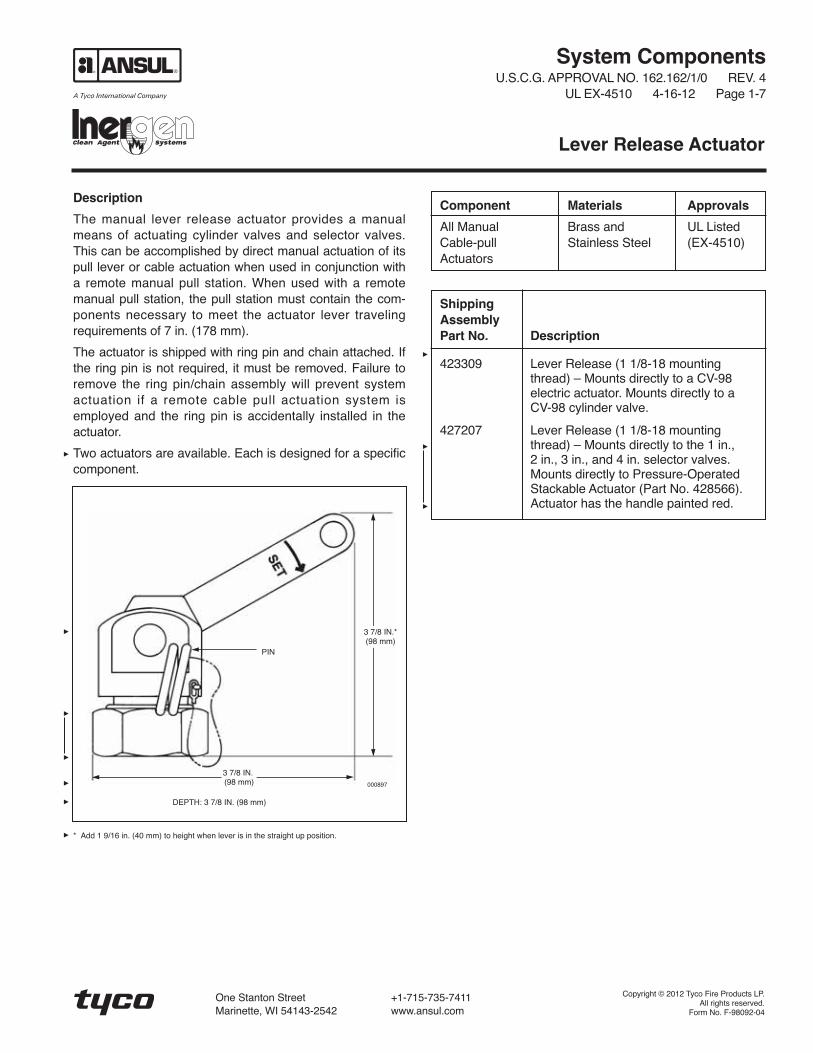
Description
The manual lever release actuator provides a manualmeans of actuating cylinder valves and selector valves.This can be accomplished by direct manual actuation of itspull lever or cable actuation when used in conjunction witha remote manual pull station. When used with a remotemanual pull station, the pull station must contain the com-ponents necessary to meet the actuator lever travelingrequirements of 7 in. (178 mm).
The actuator is shipped with ring pin and chain attached. Ifthe ring pin is not required, it must be removed. Failure toremove the ring pin/chain assembly will prevent systemactuation if a remote cable pull actuation system isemployed and the ring pin is accidentally installed in theactuator.
Two actuators are available. Each is designed for a specificcomponent.
Lever Release Actuator
Component Materials Approvals
All Manual Brass and UL ListedCable-pull Stainless Steel (EX-4510)Actuators
3 7/8 IN.(98 mm)
DEPTH: 3 7/8 IN. (98 mm)
3 7/8 IN.*(98 mm)
000897
* Add 1 9/16 in. (40 mm) to height when lever is in the straight up position.
PIN
ShippingAssemblyPart No. Description
423309 Lever Release (1 1/8-18 mountingthread) – Mounts directly to a CV-98electric actuator. Mounts directly to aCV-98 cylinder valve.
427207 Lever Release (1 1/8-18 mountingthread) – Mounts directly to the 1 in.,2 in., 3 in., and 4 in. selector valves.Mounts directly to Pressure-OperatedStackable Actuator (Part No. 428566).Actuator has the handle painted red.
Copyright © 2012 Tyco Fire Products LP.All rights reserved.
Form No. F-98092-04
One Stanton Street +1-715-735-7411Marinette, WI 54143-2542 www.ansul.com

System ComponentsU.S.C.G. APPROVAL NO. 162.162/1/0 REV. 2
UL EX-4510 4-16-12 Page 1-8
Description
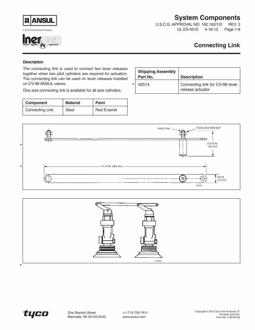
The connecting link is used to connect two lever releasestogether when two pilot cylinders are required for actuation.The connecting link can be used on lever releases installedon CV-98 ANSUL valves.
One size connecting link is available for all size cylinders.
Connecting Link
Shipping AssemblyPart No. Description
42514 Connecting link for CV-98 leverrelease actuator
Component Material Paint
Connecting Link Steel Red Enamel
001885
PIVOT PIN
14 1/4 IN. (362 mm)
3/4 IN.(19 mm)
FLEXLOCK HEX NUT
007978
2 5/16 IN.(59 mm)
Copyright © 2012 Tyco Fire Products LP.All rights reserved.
Form No. F-98105-02
One Stanton Street +1-715-735-7411Marinette, WI 54143-2542 www.ansul.com


System ComponentsU.S.C.G. APPROVAL NO. 162.162/1/0 REV. 2
UL EX-4510 4-16-12 Page 1-9
THIS PAGE INTENTIONALLYLEFT BLANK


Description
The pull box on an INERGEN system is used to providemechanical release of the system from a manually operat-ed remote station. Two types of pull boxes are available.The latched door type has a solid cast brass door whichmust be opened to reach the pull handle. The second typehas a break glass window and a spring mounted handlewhich rotates forward for use when the glass is broken. A3/8 in. female NPT opening is provided at the back of eachenclosure for connection of the cable housing. Both typesare painted red.
A pulley elbow may be attached directly to the back of thepull box, if necessary, to provide immediate changes in pullcable direction. With this option, the pull box can beextended an additional 3 1/2 in. (89 mm) from the mountingsurface by using support legs attached to the back of thepull box (one set for latched door type, two sets for break-glass type).
System ComponentsU.S.C.G. APPROVAL NO. 162.162/1/0 REV. 2
UL EX-4510 4-16-12 Page 1-10a
Manual Pull Box
Component Material Approvals
Latch door Brass UL Listed (EX-4510)pull box (painted red)
Break glass Brass UL Listed (EX-4510)window pull (painted red)box
Support legs Brass UL Listed (EX-4510)(painted red)
Shipping AssemblyPart No. Description
45062 Latch door type pull box41527 Break-glass window pull box41542 Support legs
Manual Pull Box Latched Door Type (Part No. 45062)KNOB TOOPEN PULLBOX DOORLEAD AND
WIRE SEAL –BROKENSIMULTANEOUSLYWHEN KNOB ISPULLED
HINGEDDOOR (CASTBRONZE –PAINTED RED)
MOISTURE-PROOFJOINT
3/8 IN. NPT
PULLHANDLE(BRASS)
FOR FIRE
OPEN DOOR
PULL HANDLE HARD
STAINLESSSTEEL PULLCABLE
3/8 IN. PIPEFOR ENCLOSINGPULL CABLE
BODY (CASTBRONZE –PAINTED RED)
1 7/16 IN.(36 mm)
1 15/16 IN.(49 mm)
4 3/16 IN.(106 mm)
4 1/8 IN.(104 mm)
000684b
000684a

Manual Pull Box Break Glass Type “A” (Part No. 41527)
2 13/16 IN.(71 mm)
MOISTUREPROOF JOINT
PULLHANDLE
GLASS FRONT
CAST BRASSHINGED COVER(PAINTED RED)
CAST BRASS BODY(PAINTED RED)
3/8 IN. STAINLESSSTEEL PULL CABLE
STOWAGE SPACEFOR SPAREBREAK GLASS
SPRING FORCESHANDLE OUT INTOOPERATINGPOSITION WHENGLASS IS BROKEN
3/8 IN. PIPE TOENCLOSE PULL CABLE
BRASS HAMMERAND CHAINSECURED TO BOX
4 – 3/16 IN. MOUNTING HOLES
PROTECTED HAZARDENGRAVED INNAMEPLATE (SPECIFY)
IN CASE OF FIREBREAK GLASS AND
PULL HANDLE HARDUNTIL RED PAINTMARK ON CABLE
SHOWS
3 1/4 IN.(83 mm)
4 7/16 IN.(112 mm)
4 7/8 IN.(123 mm)
3 IN.(76 mm)
000676a
000676b
System ComponentsU.S.C.G. APPROVAL NO. 162.162/1/0 REV. 2UL EX-4510 4-16-12 Page 1-10b
Copyright © 2012 Tyco Fire Products LP.All rights reserved.
Form No. F-98093-02
One Stanton Street +1-715-735-7411Marinette, WI 54143-2542 www.ansul.com

System ComponentsU.S.C.G. APPROVAL NO. 162.162/1/0 REV. 2
UL EX-4510 4-16-12 Page 1-11
Description
The pull box on an INERGEN system provides mechanicalrelease of the system or directional valve from a manuallyoperated remote station. To operate, release both latchesand open the door. Break the glass with the hammerattached to side of box. When the glass is broken, a springrotates the handle forward for a straight pull.
Combination Latch and Break Glass Pull Box
Shipping AssemblyPart No. Description
43827 Latch type pull box
42329 Type “B” Latch type pull box(watertight)
3 1/8 IN.(79 mm)
MOISTUREPROOF JOINT
PULLHANDLE
GLASS FRONT
DRAIN HOLE
CAST BRASSHINGED COVER
“O” RINGGASKET
CAST BRASS HINGEDFRONT WITH GLASS
LEVER TYPELATCH
BRASS HAMMERAND CHAINSECURED TO BOX
4 – 9/32 IN. DIAMETERMOUNTING HOLES
PROTECTED HAZARDENGRAVED INNAMEPLATE (SPECIFY)
IN CASE OF FIRERELEASE LATCHES,OPEN DOOR, BREAK
GLASS AND PULLHANDLE HARD UNTILRED PAINT MARK ON
CABLE SHOWS
CAST BRASS BODY(PAINTED RED)
1/8 IN. STAINLESSSTEEL PULL CABLE
STOWAGE SPACEFOR SPAREBREAK GLASS
SPRING FORCESHANDLE OUT INTOOPERATINGPOSITION WHENGLASS IS BROKEN
3/8 IN. CONDUIT TOENCLOSE PULL CABLE
3 1/4 IN.(83 mm)
6 3/4 IN.(171 mm)
4 7/8 IN.(124 mm)
3 IN.(76 mm)
000680
Component Material Approvals
Latch-type Brass UL Listedpull box (painted red) (EX-4510)
Watertight latch- Brass UL Listedtype pull box (painted red) (EX-4510)
Copyright © 2012 Tyco Fire Products LP.All rights reserved.
Form No. F-98094-02
One Stanton Street +1-715-735-7411Marinette, WI 54143-2542 www.ansul.com


System ComponentsU.S.C.G. APPROVAL NO. 162.162/1/0 REV. 2
UL EX-4510 4-16-12 Page 1-11.1
Description
The double pull box on an INERGEN system providesmechanical release of the pilot cylinders and the directionalvalve from a manually operated remote station. To reachthe pull handles, release the cover latch and open the door.When the door opens, the microswitch activates the systemalarm and system indicators or devices. Pull the CYLIN-DER RELEASE handle to open the pilot cylinders. Pull theVALVE RELEASE handle to open the selector valve to theprotected space.
Enclosed Double Cable Pull Box with Microswitch
Shipping AssemblyPart No. Description
426312 Enclosed Double Cable PullBox with Microswitch
18 NPT
SIDE VIEW OF CABLE PULL
INSIDE VIEW SHOWING CABLE PULLS AND MICROSWITCH6 IN. (152 mm) DEEP
Part No. 426312
004201
Component Material Approvals
Double Pull Box Steel
Cable Pull Brass
Enclosed Assembly UL Listed (EX-4510)
3 IN.(76 mm)
10 IN.(254 mm)
12 IN.(305 mm)
13 IN.(330 mm)
Copyright © 2012 Tyco Fire Products LP.All rights reserved.
Form No. F-99103-02
One Stanton Street +1-715-735-7411Marinette, WI 54143-2542 www.ansul.com


System ComponentsU.S.C.G. APPROVAL NO. 162.162/1/0 REV. 2
UL EX-4510 4-16-12 Page 1-12a
Description
The 1/16 in. (2 mm) diameter cable is used to attachremote manual pull boxes to cylinder valves, pull equalizersand control boxes. The cable is constructed of stranded,stainless steel wire. The cable is available in lengths of 50,100, and 150, (15.2, 30.5, and 45.7 m). The cable assem-blies include a brass swaged end fitting for attaching to theremote pull box.
The cable clamp is used to create a loop in the wire ropefor attachment of the wire rope to a lever release actuator.
The Flared End Fitting provides a smooth transition on theend of a pipe run for the pull cable. When the wire ropeexits the pipe to connect to lever actuators on pilot cylin-ders, selector valves, or globe valves the fitting preventschaffing of the wire rope due to sharp edges on the end ofthe pipe. Use the flared end fitting on pipe ends any timethe wire rope extends beyond the piping.
Cable with Swaged End Fitting
Component Material Approvals
Cable Stainless Steel
Swaged Fitting Brass
Cable Assembly UL Listed (EX-4510)
Shipping AssemblyPart No. Description
42104 50 ft (15.2 m) 1/16 in. (2 mm)cable with swaged end fitting
42109 100 ft (30.5 m) 1/16 in. (2 mm)cable with swaged end fitting
42113 150 ft (45.7 m) 1/16 in. (2 mm)cable with swaged end fitting
45333 1/16 in. (2 mm) cable clamp
40060 Flared End Fitting
Note: The strength of the end fitting exceeds the breaking point of the cable.
000689a
000689b
SLOT IN COUPLING FOR INSTALLATIONOF CABLE END FITTING
HANDLE
CABLE END(BRASS)
COUPLING
STAINLESS STEEL CABLE WITH SWAGED CABLE END FORPULL BOX, CABLE END HAVING RED PAINT MARK

ALLEN HEADSET SCREW
1/16 IN. CABLE
CABLE CLAMP
1/2 IN.(13 mm)
1/2 IN.(13 mm)
1/4 IN.(6 mm)
Cable Clamp (Part No. 45333)
000693
000691
3/8 IN.STANDARDPIPE THREAD
27/64 IN.(11 mm)
1 IN.(25 mm)
7/8 IN. HEX(22 mm)
Flared End Fitting (Part No. 40060)
System ComponentsU.S.C.G. APPROVAL NO. 162.162/1/0 REV. 2UL EX-4510 4-16-12 Page 1-12b
Copyright © 2012 Tyco Fire Products LP.All rights reserved.
Form No. F-98095-02
One Stanton Street +1-715-735-7411Marinette, WI 54143-2542 www.ansul.com

System ComponentsU.S.C.G. APPROVAL NO. 162.162/1/0 REV. 2
UL EX-4510 4-16-12 Page 1-13
Description
The corner pulley is required on an INERGEN systemwhenever a mechanical release pull cable run involvesa change in direction. Corner pulleys are installed as partof the cable housing (pipe) and provide 90° directionchanges with minimal force loss and no induced kinking.
The corner pulley is made of forged brass and is threadedfor 3/8 in. NPT pipe. The pulley is watertight and isdesigned for location inside or outside the protected space.Thread adaptors are available to simplify the installation.
Corner Pulley
ThreadComponent Material Size/Type Approvals
Corner Brass 3/8 in. NPT UL ListedPulley (EX-4510)
Shipping AssemblyPart No. Description
45515 Brass corner pulley(brass wheel)
40696 Thread adaptor – right/left hand(brass pulley only)
Forged Brass Watertight Corner Pulley,Sheave Type (Part No. 45515)
4 3/16 IN.(106 mm)
2 11/16 IN.(17 mm)
3/8 IN. NPT
LEAD-CLADCOPPERGASKET
3/8 IN. PIPE
REMOVABLEFACE FORRUNNING CABLE
ADAPTOR
000690b
000690a
1 5/32 IN.(29 mm)
Copyright © 2012 Tyco Fire Products LP.All rights reserved.
Form No. F-98096-02
One Stanton Street +1-715-735-7411Marinette, WI 54143-2542 www.ansul.com


System ComponentsU.S.C.G. APPROVAL NO. 162.162/1/0 REV. 2
UL EX-4510 4-16-12 Page 1-14
Description
The dual/triple control boxes allow manual actuation of acylinder valve from two or three remote pull stations. Twostyles of control boxes are available. Part No. 42784 is13 3/4 in. (349 mm) and Part No. 43166 is 20 3/4 in.(527 mm) long. Both styles can be used for cylinder valveactuation. Only the longest control box (Part No. 43166)can be used for valves utilizing sectors (globe valves). Theinlet and outlet connections are threaded for 3/8 in. pipe.
Dual/Triple Control Boxes
Shipping AssemblyPart No. Description
42784 Dual/triple control box (short)43166 Dual/triple control box (long)
Component Material Thread Size/Type Approvals
Control Box (short) Steel 3/8 in. NPT Female UL Listed (EX-4510)
Control Box (long) Steel 3/8 in. NPT Female UL Listed (EX-4510)
Short Control Box (Shown without cover) (Part No. 42784)
13 3/4 IN. (349 mm)(OVERALL)
12 1/4 IN.(311 mm)
DIRECTION OF PULLCABLE CLAMP
CABLE PULL FROMPULL-BOXES
REMOVABLE COVER
5/8 IN. (15 mm)
1 7/8 IN. (47 mm)
11/16 IN.(17 mm)
1/2 IN. (12 mm)
1 IN. (25 mm)
2 3/4 IN.(69 mm)
3 1/4 IN. (82 mm)
CABLE – PULL TOCYLINDERRELEASE
3/8 IN. PIPE
FLEXIBLE TRANSPARENTPROTECTION RING
4 – 9/32 IN. (71 mm)MOUNTING HOLES
000685a
End View
000685b
CLAMP WITHINBLACK AREA
Long Control Box (Shown without cover) (Part No. 43166)
20 3/4 IN.(527 mm)
19 1/4 IN.(488 mm)
DIRECTION OF PULLCABLE CLAMP
CABLE PULL FROMPULL-BOXES
REMOVABLE COVER
5/8 IN. (15 mm)
11/16 IN.(17 mm)
1/2 IN. (12 mm)
1 IN. (25 mm)
3 1/4 IN. (82 mm)
CABLE – PULL TOCYLINDERRELEASE
3/8 IN. PIPE
FLEXIBLE TRANSPARENTPROTECTION RING
4 – 9/32 IN. (71 mm)MOUNTING HOLES
000685a
End View
000685b
CLAMP WITHINBLACK AREA
2 3/4 IN.(69 mm)
1 7/8 IN. (47 mm)
Copyright © 2012 Tyco Fire Products LP.All rights reserved.
Form No. F-98097-02
One Stanton Street +1-715-735-7411Marinette, WI 54143-2542 www.ansul.com


System ComponentsU.S.C.G. APPROVAL NO. 162.162/1/0 REV. 2
UL EX-4510 4-16-12 Page 1-15
Description
The remote cable pull equalizer is used in systems wheremanual actuation of the cylinder valve and operation of aselector valve must be accomplished at the same time. Thepull equalizer is mounted in the remote pull station cableline. By pulling the remote pull box, the cable attached tothe pull equalizer will pull the internal cable clamp in thepull equalizer which in turn will pull the cables attached tothe cylinder valve and selector valve, causing them to oper-ate. Two styles of pull equalizers are available. Part No.42791 is 13 3/4 in. (349 mm) long and Part No. 43168 is
20 3/4 in. (527 mm). Only the longest equalizer (Part No.43168) can be used for valves utilizing sectors. The inletand outlet connections are threaded for 3/8 in. pipe.
Remote Cable Pull Equalizer
Shipping AssemblyPart No. Description
42791 Remote cable pull equalizer(short)
43168 Remote cable pull equalizer(long)
Component Material Thread Size/Type Approvals
Pull Equalizer (short) Steel 3/8 in. NPT Female UL Listed (EX-4510)
Pull Equalizer (long) Steel 3/8 in. NPT Female UL Listed (EX-4510)
Short Equalizer Box (Shown Without Cover) (Part No. 42791)
End View
3 1/4 IN.(82 mm)
2 3/4 IN.(69 mm)
1 7/8 IN.(47 mm)
11/16 IN.(17 mm)
REMOVABLE COVER
1 IN.(25 mm)
12 1/4 IN.(311 mm)
13 3/4 IN. (349 mm)(OVERALL)
DIRECTIONOF PULL
CABLE TO PULL BOX
001844a
001844b
FLEXIBLE TRANSPARENTPROTECTION RING
CABLE CLAMP
CABLE FROMCYLINDER ANDVALVE RELEASES
4 – 9/32 IN. (71 mm)MOUNTING HOLES
3/8 IN. PIPE
Long Equalizer Box (Shown Without Cover) (Part No. 43168)
3 1/4 IN.(82 mm)
2 3/4 IN.(69 mm)
1 7/8 IN.(47 mm)
11/16 IN.(17 mm)
REMOVABLE COVER
1 IN.(25 mm)
19 1/4 IN.(488 mm)
20 3/4 IN. (527 mm)(OVERALL)
DIRECTIONOF PULL
CABLE TO PULL BOX
FLEXIBLE TRANSPARENTPROTECTION RING
CABLE CLAMP
CABLE FROMCYLINDER ANDVALVE RELEASES
4 – 9/32 IN. (71 mm)MOUNTING HOLES
3/8 IN. PIPE
End View
001844a
001844b
Copyright © 2012 Tyco Fire Products LP.All rights reserved.
Form No. F-98098-02
One Stanton Street +1-715-735-7411Marinette, WI 54143-2542 www.ansul.com


System ComponentsU.S.C.G. APPROVAL NO. 162.162/1/0 REV. 2
UL EX-4510 4-16-12 Page 1-16a
Description
The marine actuation station is used to release the systempilot cylinders by means of compressed nitrogen gas. Thisis accomplished by pulling the operating handle markedCYLINDER RELEASE which punctures the nitrogen car-tridge, allowing the gas to flow to a pilot port located on thepilot cylinders, and pulling the operating handle markedVALVE RELEASE which punctures the nitrogen cartridge,allowing the gas to flow to a pressure operated selectorvalve.
The marine actuation station comes equipped with 1/4 in.stainless steel compression fittings for attaching 1/4 in. ODstainless steel tubing. The enclosure is rainproof, construct-ed of 16 ga. galvanized steel and is equipped with a drawpull catch.
Actuation pressure is achieved by means of an LT-20-LNitrogen cartridge (Part No. 7012).
Marine Actuation Station – Two Step – (S.O.L.A.S.)
INSTRUCTIONCHART
TOVALVE
TOCYLINDER
PULL CATCH
NITROGENCARTRIDGE
000694
10 IN.(254 mm)
VALVE
REL
CYLINDER
REL
COMPRESSIONFITTING FOR 1/4 IN.OD S.S. TUBE
12 IN.(305 mm)
6 IN.(152 mm)
13 IN.(330 mm)
3 IN.(76 mm)
ShippingAssembly Part No. Description
418731 Marine Actuation Station – Two Step
7012 LT-20-L Nitrogen Cartridge
Component Material Approvals
Marine Actuation Steel UL ListedStation – Two Step (EX-4510)

001382
MAXIMUM LENGTH RUN (FEET)0 50 100 150 200 250 300
WA
LL
TH
ICK
NE
SS
(IN
CH
ES
)
1/4 IN. STAINLESSSTEEL TUBE
0.028
0.035
0.049
0.065
5867
94
150
0.020
0.025
0.030
0.035
0.040
0.045
0.050
0.055
0.060
0.065
0.070
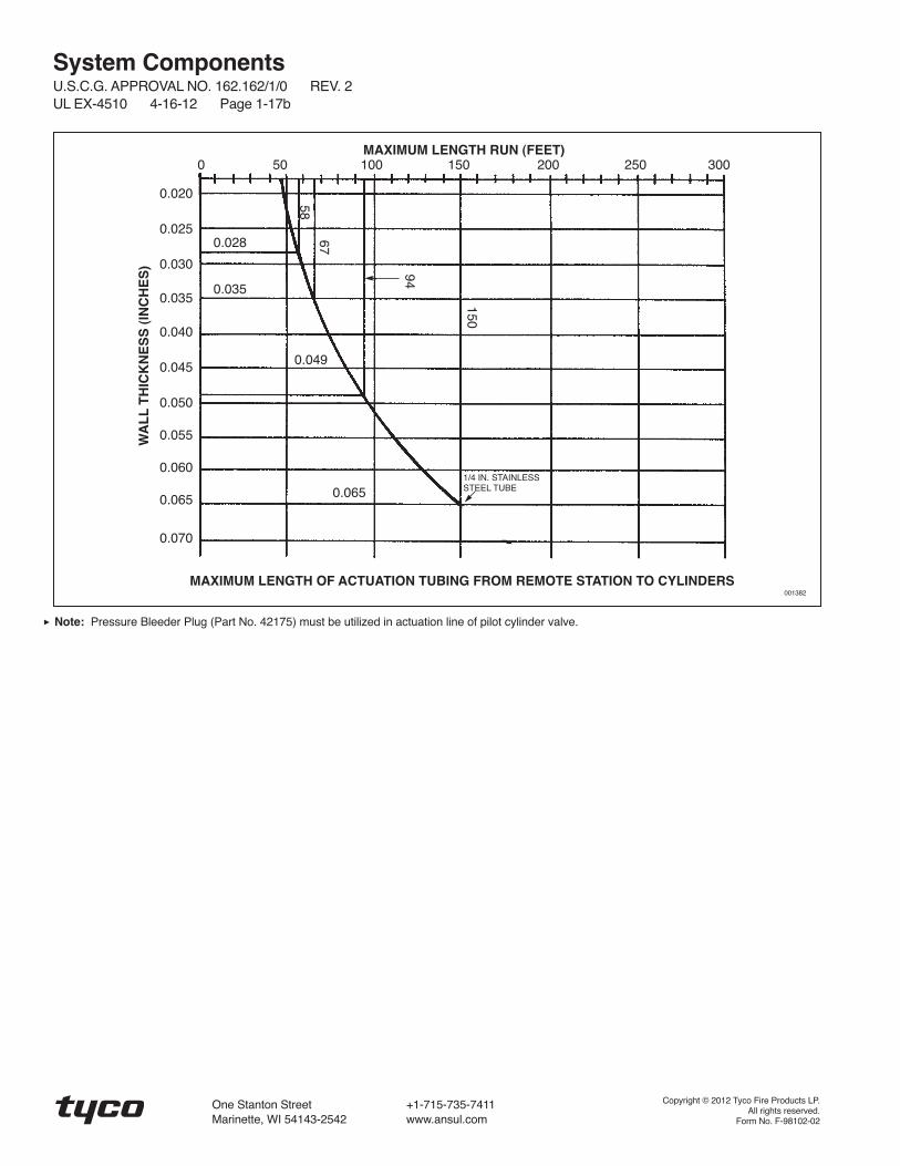
Note: Pressure Bleeder Plug (Part No. 42175) must be utilized in actuation line of pilot cylinder valve.
MAXIMUM LENGTH OF ACTUATION TUBING FROM REMOTE STATION TO CYLINDERS
System ComponentsU.S.C.G. APPROVAL NO. 162.162/1/0 REV. 2UL EX-4510 4-16-12 Page 1-16b
Copyright © 2012 Tyco Fire Products LP.All rights reserved.
Form No. F-98101-02
One Stanton Street +1-715-735-7411Marinette, WI 54143-2542 www.ansul.com
System ComponentsU.S.C.G. APPROVAL NO. 162.162/1/0 REV. 2
UL EX-4510 4-16-12 Page 1-17a
Description
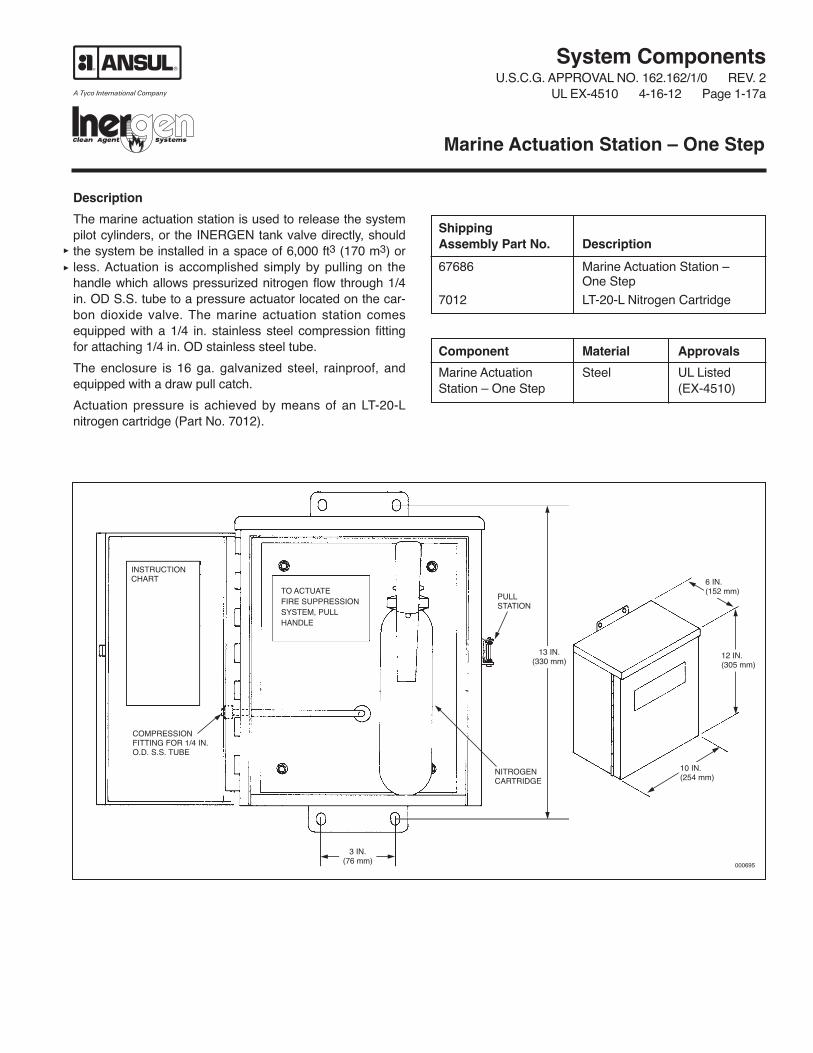
The marine actuation station is used to release the systempilot cylinders, or the INERGEN tank valve directly, shouldthe system be installed in a space of 6,000 ft3 (170 m3) orless. Actuation is accomplished simply by pulling on thehandle which allows pressurized nitrogen flow through 1/4in. OD S.S. tube to a pressure actuator located on the car-bon dioxide valve. The marine actuation station comesequipped with a 1/4 in. stainless steel compression fittingfor attaching 1/4 in. OD stainless steel tube.
The enclosure is 16 ga. galvanized steel, rainproof, andequipped with a draw pull catch.
Actuation pressure is achieved by means of an LT-20-Lnitrogen cartridge (Part No. 7012).
Marine Actuation Station – One Step
NITROGENCARTRIDGE
COMPRESSIONFITTING FOR 1/4 IN.O.D. S.S. TUBE
PULLSTATION
INSTRUCTIONCHART
000695
TO ACTUATEFIRE SUPPRESSIONSYSTEM, PULLHANDLE
6 IN.(152 mm)
12 IN.(305 mm)
10 IN.(254 mm)
ShippingAssembly Part No. Description
67686 Marine Actuation Station – One Step
7012 LT-20-L Nitrogen Cartridge
Component Material Approvals
Marine Actuation Steel UL ListedStation – One Step (EX-4510)
3 IN.(76 mm)
13 IN.(330 mm)
001382
MAXIMUM LENGTH RUN (FEET)0 50 100 150 200 250 300
WA
LL
TH
ICK
NE
SS
(IN
CH
ES
)
1/4 IN. STAINLESSSTEEL TUBE
0.028
0.035
0.049
0.065
58
67
94
150
0.020
0.025
0.030
0.035
0.040
0.045
0.050
0.055
0.060
0.065
0.070
Note: Pressure Bleeder Plug (Part No. 42175) must be utilized in actuation line of pilot cylinder valve.
MAXIMUM LENGTH OF ACTUATION TUBING FROM REMOTE STATION TO CYLINDERS
System ComponentsU.S.C.G. APPROVAL NO. 162.162/1/0 REV. 2UL EX-4510 4-16-12 Page 1-17b
Copyright © 2012 Tyco Fire Products LP.All rights reserved.
Form No. F-98102-02
One Stanton Street +1-715-735-7411Marinette, WI 54143-2542 www.ansul.com

System ComponentsU.S.C.G. APPROVAL NO. 162.162/1/0 REV. 2
UL EX-4510 4-16-12 Page 1-17.1
Description
The extended distance marine actuation method is used torelease the system pilot cylinders and open the selectorvalve by means of INERGEN agent when the distancebetween pilot cylinder/selector valve and the remote actua-tion location exceeds the limits of the marine actuation sta-tion. Actuation is accomplished by pulling the lever of eachmanual actuator located on top of each cylinder valve. Onecylinder should be piped to the pilot cylinder valve and theother cylinder should be piped to the pressure operatedselector valve.
Utilizing a 200 cu ft INERGEN cylinder*, piped through1/4 in. stainless steel tubing (0.028 in. minimum wall thick-ness), the maximum length of tubing allowed is 600 ft(182.9 m).
See Page 1-18 for connection at the pilot cylinders.
Instruction plates are available for mounting next to eachcylinder.
Extended Distance Marine Actuation Method – Two Step (Utilizing 200 cu ft INERGEN Cylinders)
Quantity Part No. Description
2 426147 200 cu ft INERGEN CylinderShipping Assembly*
2 427082 Flexible Discharge Bend2 423309 Lever Release Actuator2 79638 Back Frame Assembly
(2 Cylinder)2 73251 11 in. (279 mm) Carriage Bolt
with Nut2 73091 Cylinder Clamp (2 Cylinder)
LEVERRELEASEACTUATOR(S)
006626
BRACKETCOMPONENTS
TO PILOTCYLINDER
TO SELECTORVALVE**
Note: Flexible discharge bend outlet is 1/2 in. NPT malethread. Adaptor (sup plied by others) must be usedto connect to 1/4 in. stainless steel tube fitting.
*Note: Alternate 250 cu ft INERGEN cylinders, Part No.426148 can be used in place of the 200 cu ftcylinders.
**Note: When connecting the pneumatic actuation linefrom 200 or 250 cu ft Extended Distance MarineActuation Cylinders, a Bleeder Plug (Part No.42175) should be installed in the pneumatic linenear the stop or selector valve.
FLEXIBLEDISCHARGEBEND(S)
200 CU FTINERGENCYLINDER(S)*
1/2 IN. NPTMALE THREAD
Copyright © 2012 Tyco Fire Products LP.All rights reserved.
Form No. F-2005053-02
One Stanton Street +1-715-735-7411Marinette, WI 54143-2542 www.ansul.com


System ComponentsU.S.C.G. APPROVAL NO. 162.162/1/0 REV. 1
UL EX-4510 4-16-12 Page 1-17.2
Selector/Isolation ValvePneumatic Actuation
The selector valves and 3/4 in. isolation valve can be pneu-matically actuated by the Marine Actuation Station. Use theSelector Valve Pneumatic Actuation Line Kit to control thepressure in the actuation line. One Selector ValvePneumatic Actuation Line Kit is required for each pneumaticactuator and must be installed within 1 ft (0.3 m) of thepneumatic actuator/isolation valve. The Low Pressure VentPlug and Safety Relief Valve are to be installed with atorque of 125 in.-lb (14 Nm). After system discharge, allpressure in the actuation line must be relieved by pullingthe ring on the safety relief valve.
Part No. Description______ __________428566 Pressure Operated Stackable Actuator*
41702 3/4 in. Pressure Operated Isolation Valve
436127 Selector Valve Pneumatic Actuation Line Kit(Kit includes Low Pressure Vent Plug(Part No. 436085), Safety Relief Valve (Part No.15677), 1/4 in. Close Nipple (Part No. 28484),and 1/4 in. Tee (Part No. 27350))
*Note: The Pressure Operated Stackable Actuator is only required on selectorvalves.
008204
PRESSURE OPERATEDSTACKABLE ACTUATOR(PART NO. 428566)
1 IN., 2 IN., 3 IN., OR 4 IN.SELECTOR VALVE(4 IN. SHOWN)
TO MARINE ACTUATION STATIONFOR ʻVALVE RELEASEʼ
THE ACTUATION LINE KIT IS USED ONLYWHEN BEING PRESSURIZED FROM ANLT-20 CARTRIDGE OF A REMOTEMANUAL STATION. WHEN CONNECTEDTO 200 OR 250 CU FT EXTENDEDDISTANCE ACTUATION CYLINDERS, USEA BLEEDER PLUG (PART NO. 42175) INPLACE OF THE ACTUATION LINE KIT.
008334
SELECTOR VALVE PNEUMATICACTUATION LINE KIT (PART NO. 436127)
SELECTOR VALVE PNEUMATICACTUATION LINE KIT(PART NO. 436127)
3/4 IN. PRESSURE ACTUATED ISOLATIONVALVE (PART NO. 41702)
TO MARINEACTUATIONSTATION
1/4 IN. TEE
LOW PRESSUREVENT PLUG
SAFETYRELIEF VALVE
1/4 IN. CLOSENIPPLE
4 3/4 IN.(121 mm)
1 3/4 IN.(44 mm)
008246
Copyright © 2012 Tyco Fire Products LP.All rights reserved.
Form No. F-2010259-01
One Stanton Street +1-715-735-7411Marinette, WI 54143-2542 www.ansul.com


System ComponentsU.S.C.G. APPROVAL NO. 162.162/1/0 REV. 3
UL EX-4510 4-16-12 Page 1-18
Description
The Pilot Valve Actuation Adaptor and fittings are used inlarge INERGEN systems requiring more than one pilotcylinder. This is required in systems where, because of thesize of the union orifice, low manifold pressure can be pro-duced which is not high enough to adequately operate theremaining cylinders on the manifold.
To overcome this, additional pilot cylinders, pneumaticallyoperated through the pilot actuation port, are required.
Refer to system design to determine if additional pilot cylin-ders are required in the system.
Note: Systems comprising three or more cylinders mustuse a minimum of two pilot cylinders.
Pilot Valve Actuation Adaptor
Shipping AssemblyPart No. Description
73236 Pilot valve actuator adaptor
32334 Male elbow
418359 Flared tee
TEE (PARTNO. 418359)(TYP.)
MALE ELBOW (PARTNO. 32334) (TYP.)
TO MARINEACTUATIONSTATION
1/4 IN. CHECK VALVE (PART NO. 25627)
ADAPTOR(PART NO.73236) (TYP.)
16 IN. STAINLESS STEEL HOSE (PART NO. 31809) (TYP.)
STRAIGHT ADAPTOR(PART NO. 32338)(OR ELBOW, PART NO. 31810)
003636
Component Material Approvals
Pilot valve Brass UL Listed (EX-4510)actuator adaptor
Male elbow Brass UL Listed (EX-4510)
Flared tee Brass UL Listed (EX-4510)
Copyright © 2012 Tyco Fire Products LP.All rights reserved.
Form No. F-98099-03
One Stanton Street +1-715-735-7411Marinette, WI 54143-2542 www.ansul.com


System ComponentsU.S.C.G. APPROVAL NO. 162.162/1/0 REV. 2
UL EX-4510 4-16-12 Page 1-19
Description
The Stainless Steel Actuation Hose is used to connect theactuation line compression tees between each agent tank.The hose has the same thread, 7/16-20, as the compres-sion tees. The actuation hose allows flexibility between therigid actuation piping and the tank valve.
Additional actuation fittings are available:
Part No. Description_______ _________
31810 Male Elbow (7/16-20 x 1/4 in. NPT)31811 Male Tee (7/16-20 x 7/16-20 x 1/4 in. NPT)32338 Male Straight Connector (7/16-20 x 1/4 in. NPT)418359 Flared Tee (7/16 – 20 x 7/16 – 20 x 1/8 in. NPT)73236 Pilot Valve Actuation Adaptor32334 Male Elbow (7/16 – 20 Flare x 1/8 in. NPT)
Stainless Steel Actuation Hose
Shipping AssemblyPart No. Description
31809 16 in. (406 mm) StainlessSteel Hose
32335 20 in. (508 mm) StainlessSteel Hose
32336 24 in. (609 mm) StainlessSteel Hose
Component Material Thread Size Approvals
Stainless Steel Stainless Steel Female 7/16-20 UL Listed (EX-4510)Hose (Both ends)
24 IN.(610 mm)
7/16-20
000433
7/16-20
Copyright © 2012 Tyco Fire Products LP.All rights reserved.
Form No. F-98111-02
One Stanton Street +1-715-735-7411Marinette, WI 54143-2542 www.ansul.com


System ComponentsU.S.C.G. APPROVAL NO. 162.162/1/0 REV. 2
UL EX-4510 4-16-12 Page 1-20
Description
The pressure bleeder plug can be used to relieve the pres-sure in closed actuation lines. The plug relieves the pres-sure through a small orifice. This slow relief of pressuredoes not affect the function of the actuation line.
Pressure Bleeder Plug (Part No. 42175) must not beinstalled anywhere in the directional/selector valve actua-tion line as the directional/selector valve may not remainopen during a complete system discharge, potentiallyinterfering with the ability of the system to suppress a fire.
CAUTION
1/4 in. Pressure Bleeder Plug
Component Material Thread Size/Type Approvals
Pressure Bleeder Plug Brass 1/4 in. NPT Male UL Listed (EX-4510)
Shipping AssemblyPart No. Description
42175 Pressure Bleeder Plug
ORIFICE
1/4 in. Pressure Bleeder Plug3/8 IN.(9.5 mm)
1/4 IN. NPT
001839
3/4 IN.(19 mm)
Copyright © 2012 Tyco Fire Products LP.All rights reserved.
Form No. F-98106-02
One Stanton Street +1-715-735-7411Marinette, WI 54143-2542 www.ansul.com


System ComponentsU.S.C.G. APPROVAL NO. 162.162/1/0 REV. 2
UL EX-4510 4-16-12 Page 1-21
THIS PAGE INTENTIONALLYLEFT BLANK


System ComponentsU.S.C.G. APPROVAL NO. 162.162/1/0 REV. 1
UL EX-4510 4-16-12 Page 1-22
THIS PAGE INTENTIONALLYLEFT BLANK


Description
The header vent plug is used to release low pressure build-up that may occur in a closed system utilizing selectorvalves or check valves. The header vent plug should alsobe installed on the cylinder sides of the check valves onboth main and reserve systems to relieve any pressure thatmay leak past the check valve and accidentally actuate thereserve system while the main system is discharging.
A header vent plug must be installed in all closed sectionsof the system manifold(s). The omission of a header ventplug may cause the manifold to build pressure. This couldresult in the actuation of a system cylinder, which wouldthen cause all cylinders in that specific system to actuate.
Closing pressure is 30 psi (2.1 bar).
CAUTION
System ComponentsU.S.C.G. APPROVAL NO. 162.162/1/0 REV. 2
UL EX-4510 4-16-12 Page 1-23
Header Vent Plug
Shipping AssemblyPart No. Description
40309 Header vent plug
Component Material Thread Size/Type Approvals
Vent Plug Body: Brass 1/2 in. NPT Male UL Listed (EX-4510)
Spring: Bronze
Seal: Neoprene
SPRING
CHECK SEAL
CHECK CUP
1/2 IN. NPT
000707
STEM
BODY
WASHER
29/32 IN.(23 mm)7/8 IN.
(22 mm)
Copyright © 2012 Tyco Fire Products LP.All rights reserved.
Form No. F-98109-02
One Stanton Street +1-715-735-7411Marinette, WI 54143-2542 www.ansul.com

Description
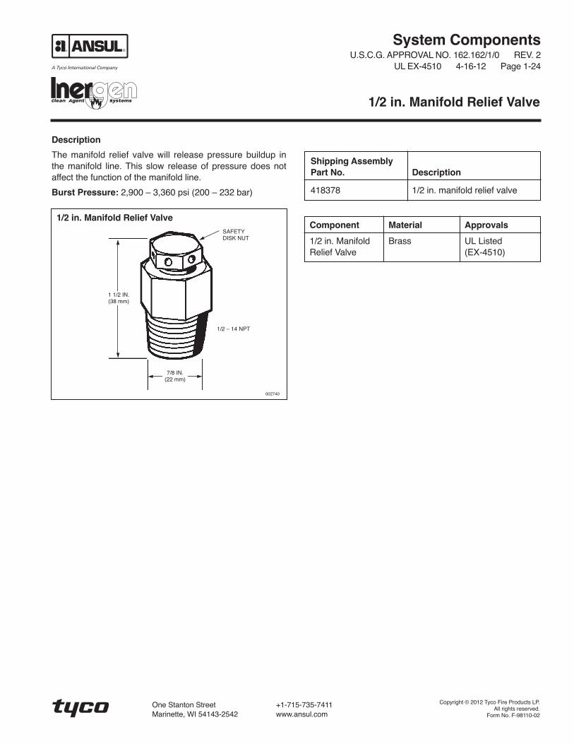
The manifold relief valve will release pressure buildup inthe manifold line. This slow release of pressure does notaffect the function of the manifold line.
Burst Pressure: 2,900 – 3,360 psi (200 – 232 bar)
System ComponentsU.S.C.G. APPROVAL NO. 162.162/1/0 REV. 2
UL EX-4510 4-16-12 Page 1-24
1/2 in. Manifold Relief Valve
Shipping AssemblyPart No. Description
418378 1/2 in. manifold relief valve
SAFETYDISK NUT
1/2 – 14 NPT
002740
1/2 in. Manifold Relief Valve
7/8 IN.(22 mm)
1 1/2 IN.(38 mm)
Component Material Approvals
1/2 in. Manifold Brass UL ListedRelief Valve (EX-4510)
Copyright © 2012 Tyco Fire Products LP.All rights reserved.
Form No. F-98110-02
One Stanton Street +1-715-735-7411Marinette, WI 54143-2542 www.ansul.com


System ComponentsU.S.C.G. APPROVAL NO. 162.162/1/0 REV. 2
UL EX-4510 4-16-12 Page 1-25
Description
In some applications, the system discharge must bedelayed for a short time following actuation. This is usuallyin areas where it is necessary to evacuate personnel priorto discharge. A manual release is incorporated on the timedelay valve to allow instant override of the time delay. Thelength of delay is factory set and is not adjustable.
The time delay assembly uses INERGEN pressure topower the factory-set delay mechanism. Install the assem-bly in the discharge piping, either directly after the control(pilot) cylinder or further along the piping. The assembly isreversible to accommodate right and left hand configura-tions and will operate in any mounting orientation. After thedischarge is complete, pressure in the assembly slowlyreturns to normal and closes the time delay valve.
Time Delay Assembly
Shipping AssemblyPart No. Description
426170 60 Second time delay
54169 30 Second time delay
000699
3/4 IN. – 14 NPT BOTH SIDES
CROSS SECTION OF VALVE
5 1/2 IN.(140 mm)
5 7/8 IN.(149 mm)
23 3/8 IN.(594 mm)
Component Material Approvals
Valve Brass
Accumulator Steel(Sch. 80 Pipe)
Time Delay UL Listed (EX-4510)Assembly
004372
Copyright © 2012 Tyco Fire Products LP.All rights reserved.
Form No. F-98104-02
One Stanton Street +1-715-735-7411Marinette, WI 54143-2542 www.ansul.com


System ComponentsU.S.C.G. APPROVAL NO. 162.162/1/0 REV. 2
UL EX-4510 4-16-12 Page 1-26a
Description
Check valves are used in main/reserve and selector valvesystems. On main/reserve systems, the check valve pre-vents pressurization of the reserve system manifold byblocking the flow of INERGEN agent from the main systemto the reserve system. The check valve allows gas flowfrom the reserve (if actuated) to pass through into the distri-bution piping. On selector valve systems, the check valveprevents the cylinders from the selected hazard from pres-surizing the manifold of the cylinders required for protectinga separate hazard. Only the cylinders needed for the partic-ular hazard are activated.
The threaded check valves are available in sizes from1/4 in. through 2 1/2 in.
Check Valves – Threaded
Shipping AssemblyPart No. Description
25627 1/4 in. check valve (pkg. of 2)40860 1/2 in. check valve40852 3/4 in. check valve41470 1 in. check valve41549 1 1/4 in. check valve41463 1 1/2 in. check valve40649 2 in. check valve40656 2 1/2 in. check valve
Check Valve – Threaded
Dimension A Dimension B Equivalent LengthValve Size in. (mm) in. (mm) Weight (Sch. 80 Pipe)
1/2 in. 3 (76) 2 5/8 (66) 2 lb (0.9 kg) 12.0 ft (3.7 m)3/4 in. 3 5/8 (92) 3 1/8 (79) 4 lb (1.8 kg) 24.0 ft (7.3 m)1 in. 4 1/8 (104) 3 3/4 (95) 7 lb (3 kg) 28.0 ft (8.5 m)1 1/4 in. 5 (127) 4 1/2 (114) 10 lb (8.7 kg) 43.0 ft (13.1 m)1 1/2 in. 5 1/2 (139) 5 1/8 (130) 13 lb (5.9 kg) 51.0 ft (15.5 m)2 in. 6 1/2 (165) 6 7/16 (164) 15 lb (6.8 kg) 48.0 ft (14.6 m)2 1/2 in. 8 (203) 6 3/4 (171) 34 lb (15.4 kg) 60.0 ft (18.3 m)
A
B
BONNET
BODY
SPRING
CHECK
DIRECTIONOF FLOW
002737
Length:1 5/8 in. (41 mm)Width: 3/4 in. (19 mm)Height: 1 1/8 in. (27 mm)
000899
1/4 in. Check Valve (Part No. 25627)
ARROW INDICATESDIRECTION OF FLOW
1/4 IN. – 18 NPT FEMALE(BOTH ENDS)

A
B
002739
2 1/2 in. Check Valve (Part No. 40656)
Component Material Thread Size/Type Body Type Approvals
Check Valve Brass 1/4 – 18 NPT Female Threaded UL Listed (EX-4510)
Check Valve Bronze 1/2-14 NPT Female Threaded UL Listed (EX-4510)
Check Valve Bronze 3/4-14 NPT Female Threaded UL Listed (EX-4510)
Check Valve Bronze 1 - 11 1/2 NPT Female Threaded UL Listed (EX-4510)
Check Valve Bronze 1 1/4 - 11 1/2 NPT Female Threaded UL Listed (EX-4510)
Check Valve Bronze 1 1/2 - 11 1/2 NPT Female Threaded UL Listed (EX-4510)
Check Valve Bronze 2 - 11 1/2 NPT Female Threaded UL Listed (EX-4510)
Check Valve Bronze 2 1/2 - 8 NPT Female Threaded UL Listed (EX-4510)
DIRECTIONOF FLOW
System ComponentsU.S.C.G. APPROVAL NO. 162.162/1/0 REV. 2UL EX-4510 4-16-12 Page 1-26b
Copyright © 2012 Tyco Fire Products LP.All rights reserved.
Form No. F-98108-02
One Stanton Street +1-715-735-7411Marinette, WI 54143-2542 www.ansul.com

Description
Check valves are used in main/reserve systems and onsystems protecting multiple hazards of different volumesusing selector valves to control the direction of agent flow.On main/reserve systems the check valve prevents pres-surization of the reserve system manifold by blocking theflow of INERGEN from the main system. The check valveallows gas flow from the reserve (if actuated) to passthrough into the distribution piping. On selector valve sys-tems, the check valve prevents the cylinders from the
selected hazard from pressurizing the manifold of the cylin-ders required for protecting a separate hazard. Only thecylinders needed for the particular hazard are activated.
The weld neck flange style valves are supplied with two (2)600 lb weld neck, flat faced, forged steel flanges, completewith bolts, nuts and gaskets. Threaded flanges with bolts,nuts, and gaskets are included with the 3 in. threadedflange valve.
System ComponentsU.S.C.G. APPROVAL NO. 162.162/1/0 REV. 2
UL EX-4510 4-16-12 Page 1-27a
Check Valves – Flanged
Component Material Thread Size/Type Body Type Approvals
Check Valve Body: Bronze N/A 2 in. Weld UL Listed (EX-4510)Flange: Steel Neck Flange
Check Valve Body: Bronze N/A 2 1/2 in. UL Listed (EX-4510)Flange: Steel Weld Neck
Check Valve Body: Bronze N/A 3 in. Weld UL Listed (EX-4510)Flange: Steel Neck Flange
Check Valve Body: Bronze 3 in. NPT Threaded UL Listed (EX-4510)Flange: Steel Flange
Shipping AssemblyPart No. Description Weight Equivalent Length
40794 2 in. check valve – weld neck flange 40 lb (18 kg) 48 ft (14.6 m)46095 2 1/2 in. check valve – weld neck flange 45 lb (20 kg) 60 ft (18.3 m)40672 3 in. check valve – weld neck flange 125 lb (57 kg) 154 ft (46.9 m)40665 3 in. check valve – threaded flange 125 lb (75 kg) 154 ft (46.9 m)

Check Valve – Weld Neck Flange
Dimension A Dimension BValve Size in. (mm) in. (mm)
2 in. 10 1/4 (260) 7 1/2 (191)2 1/2 in. 10 3/4 (273) 8 11/16 (221)
3 in. 11 1/2 (292) 9 1/2 (241)
Check Valve – Threaded Flange
Valve Dimension A Dimension B Dimension CSize in. (mm) in. (mm) in. (mm)
3 in. 11 1/2 (292) 15 (381) 9 1/2 (241)A
C
B
CHECK
BODY
BONNET
SPRING
OUTLETINLET
B
A
000683
001817
3 in. Threaded Flange
Weld Neck Flange
System ComponentsU.S.C.G. APPROVAL NO. 162.162/1/0 REV. 2UL EX-4510 4-16-12 Page 1-27b
Copyright © 2012 Tyco Fire Products LP.All rights reserved.
Form No. F-98128-02
One Stanton Street +1-715-735-7411Marinette, WI 54143-2542 www.ansul.com

Description
Globe valves are used to either manually control the flow ofINERGEN agent into a hazard area or to manually controlthe flow into one of several hazards being protected by acommon bank of INERGEN cylinders. These valves areoperated manually, either by the use of a hand leverattached directly to the valve or by meansof a remote manual pull box which will operate a sector
attached to the valve. Globe valves can be used as a safetyfeature, keeping the flow of INERGEN from entering a haz-ard area, either because of a false discharge or to allow theoccupants enough time to exit the area prior to the valvebeing manually opened. The valves are available in 1/2 in.and 3/4 in. sizes. Each size can be used with a hand leveror a sector.
Component Material Thread Size/Type Approvals
Globe Valve Forged Brass 1/2 in. NPT Female UL Listed (EX-4510)
Globe Valve Forged Brass 3/4 in. NPT Female UL Listed (EX-4510)
Shipping AssemblyPart No. Description
41451 1/2 in. direction/stop valve (valve only)41102 3/4 in. direction/stop valve (valve only)
40248 Handle – normally open (for use with 1/2 in. valve)40267 Handle – normally open (for use with 3/4 in. valve)
40238 Handle – normally closed (for use with 1/2 in. valve)40239 Handle – normally closed (for use with 3/4 in. valve)
40276 Sector (for use with 1/2 in. valve)40279 Sector (for use with 3/4 in. valve)
System ComponentsU.S.C.G. APPROVAL NO. 162.162/1/0 REV. 2
UL EX-4510 4-16-12 Page 1-28a
Globe Valves and Controls

A B C D EValve Size in. (mm) in. (mm) in. (mm) in. (mm) in. (mm)
1/2 in. 10 (254) 9 3/8 (238) 4 3/4 (121) 7/8 (22) 2 15/16 (74)3/4 in. 14 (355) 12 3/4 (323) 5 5/8 (142) 1 1/8 (28) 3 5/8 (92)
A B C DValve Size in. (mm) in. (mm) in. (mm) in. (mm)
1/2 in. 4 3/4 (121) 3 (76) 7/8 (22) 2 15/16 (74)3/4 in. 5 5/8 (142) 3 5/8 (93) 1 1/8 (28) 3 5/8 (92)
*THIS DIMENSION WITHVALVE IN OPEN POSITIONA
001427a
001427b
000674a
000674b
D
PIPE
HANDLEIN OPENPOSITION
E
B
C*
HANDLE INNORMALLYCLOSEDPOSITION
CABLECLAMP
1/2 IN. STAINLESS STEEL ORMONEL CABLE TO PULL BOX
3/4 IN. FLAREDEND FITTING
CABLE TO HAVE A SLIGHTSLACK WHEN VALVE IS INCLOSED POSITION
PROVIDE A STOP FORSECTOR AT THIS POINT
30°
4 3/4 IN.(121 mm)
7 11/16 IN.
(195 mm)
ATTACHCABLE IN“FIGURE 8(LOOP)”BEFOREFASTENINGCLAMP
D
3 3/8 IN.(85 mm)
6 13/16 IN.(173 mm)
A
B C
System ComponentsU.S.C.G. APPROVAL NO. 162.162/1/0 REV. 2UL EX-4510 4-16-12 Page 1-28b
Copyright © 2012 Tyco Fire Products LP.All rights reserved.
Form No. F-98087-02
One Stanton Street +1-715-735-7411Marinette, WI 54143-2542 www.ansul.com
System ComponentsU.S.C.G. APPROVAL NO. 162.162/1/0 REV. 3
UL EX-4510 4-16-12 Page 1-29a
Description
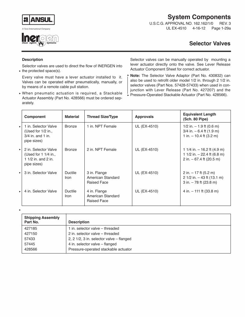
Selector valves are used to direct the flow of INERGEN intothe protected space(s).
Every valve must have a lever actuator installed to it.Valves can be operated either pneumatically, manually, orby means of a remote cable pull station.
When pneumatic actuation is required, a StackableActuator Assembly (Part No. 428566) must be ordered sep-arately.
Selector valves can be manually operated by mounting alever actuator directly onto the valve. See Lever ReleaseActuator Component Sheet for correct actuator.
Note: The Selector Valve Adaptor (Part No. 430832) canalso be used to retrofit older model 1/2 in. through 2 1/2 in.selector valves (Part Nos. 57428-57433) when used in con-junction with Lever Release (Part No. 427207) and thePressure-Operated Stackable Actuator (Part No. 428566).
Selector Valves
Component Material Thread Size/Type ApprovalsEquivalent Length(Sch. 80 Pipe)
1 in. Selector Valve Bronze 1 in. NPT Female UL (EX-4510) 1/2 in. – 1.9 ft (0.6 m)(Used for 1/2 in., 3/4 in. – 6.4 ft (1.9 m)3/4 in. and 1 in. 1 in. – 10.4 ft (3.2 m)pipe sizes)
2 in. Selector Valve Bronze 2 in. NPT Female UL (EX-4510) 1 1/4 in. – 16.2 ft (4.9 m)(Used for 1 1/4 in., 1 1/2 in. – 22.4 ft (6.8 m)1 1/2 in. and 2 in. 2 in. – 67.4 ft (20.5 m)pipe sizes)
3 in. Selector Valve Ductile 3 in. Flange UL (EX-4510) 2 in. – 17 ft (5.2 m)Iron American Standard 2 1/2 in. – 43 ft (13.1 m)
Raised Face 3 in. – 78 ft (23.8 m)
4 in. Selector Valve Ductile 4 in. Flange UL (EX-4510) 4 in. – 111 ft (33.8 m)Iron American Standard
Raised Face
Shipping AssemblyPart No. Description
427185 1 in. selector valve – threaded427150 2 in. selector valve – threaded57433 2, 2 1/2, 3 in. selector valve – flanged57445 4 in. selector valve – flanged428566 Pressure-operated stackable actuator

A B C DValve Size Body in. (mm) in. (mm) in. (mm) in. (mm)
1 in. Threaded – 5 1/2 (140) — — 2 9/16 (67) 7 (178)1 in. NPT female
2 in. Threaded – 7 1/2 (191) — — 3 1/2 (89) 8 9/16 (218)2 in. NPT female
3 in. Flanged – 3 in. 13 (330) 5 3/4 (146) 6 1/8 (156) 15 (381)
4 in. Flanged – 4 in. 16 (406) 5 3/4 (146) 8 3/4 (222) 17 3/16 (437)
006035
1 IN. AND 2 IN. THREADED VALVE
Note: A lever actuator or brass cap must be used witheach selector valve. Valve will not operate properly with-out one of these on top of pressure actuator assembly.
A
C
D
1 1/8 – 18 UNEF
System ComponentsU.S.C.G. APPROVAL NO. 162.162/1/0 REV. 3UL EX-4510 4-16-12 Page 1-29b
C
A
B
IF FLANGED007399
3 IN. AND 4 IN. FLANGED VALVE
D
1 1/8-18 UNEF
Copyright © 2012 Tyco Fire Products LP.All rights reserved.
Form No. F-98088-03
One Stanton Street +1-715-735-7411Marinette, WI 54143-2542 www.ansul.com

System ComponentsU.S.C.G. APPROVAL NO. 162.162/1/0 REV. 2
UL EX-4510 4-16-12 Page 1-30
Description
The Pressure-Operated Stackable Actuator (Part No.428566) is necessary when pneumatic actuation is requiredon any selector valve. This actuator is installed on top ofthe selector valve and a 1/4 in. pressure line must beattached to the 1/8 in. pressure port on the side of the actu-ator. The actuator must be manually reset.
Installations which utilize the pressure-operated stackableactuator must incorporate a Selector Valve PneumaticActuation Line Kit (Part No. 436127) in the directional/selector valve actuation line for each actuator. SeeComponent Page 1-17.2 for kit details.
Pressure-Operated Stackable Actuator
006036
2.309 IN.(59 mm)
2.926 IN.(74 mm)
1/8 IN.PRESSUREPORT
1 1/8 – 18 UNEF
1 1/8 – 18 UNEF
Copyright © 2012 Tyco Fire Products LP.All rights reserved.
Form No. F-2001245-02
One Stanton Street +1-715-735-7411Marinette, WI 54143-2542 www.ansul.com


System ComponentsU.S.C.G. APPROVAL NO. 162.162/1/0 REV. 3
UL EX-4510 4-16-12 Page 1-31a
THIS PAGE INTENTIONALLYLEFT BLANK

System ComponentsU.S.C.G. APPROVAL NO. 162.162/1/0 REV. 2
UL EX-4510 4-16-12 Page 1-32
Description
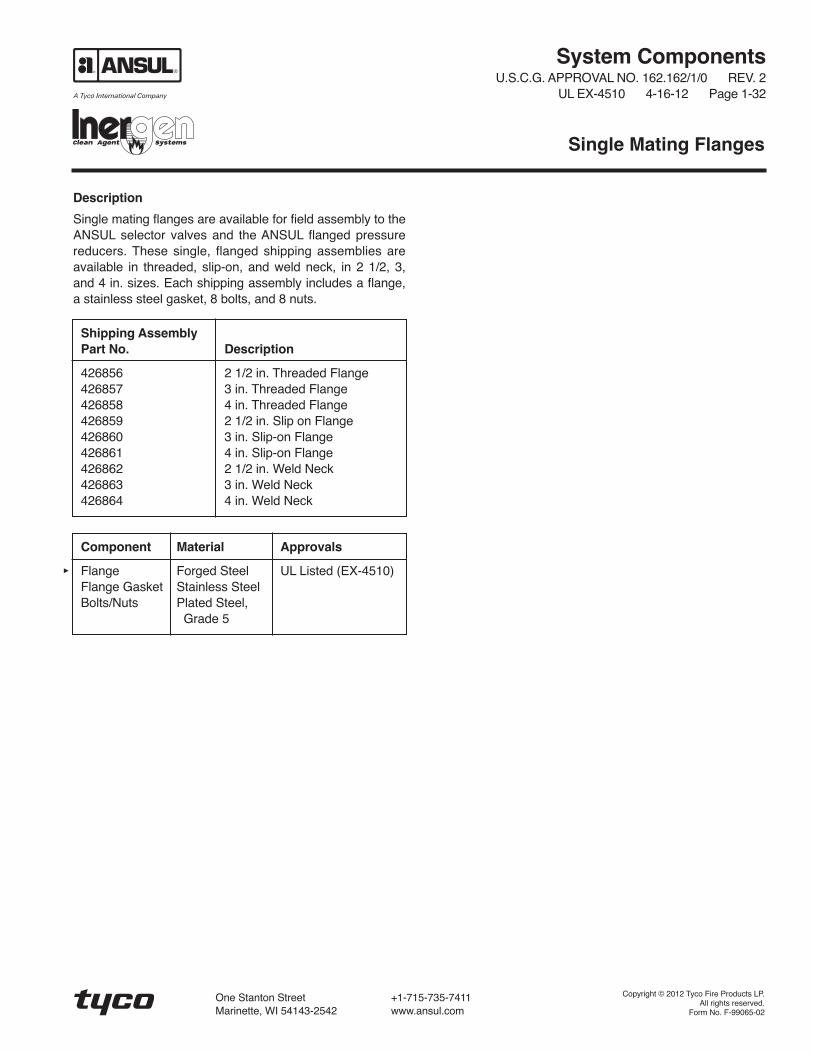
Single mating flanges are available for field assembly to theANSUL selector valves and the ANSUL flanged pressurereducers. These single, flanged shipping assemblies areavailable in threaded, slip-on, and weld neck, in 2 1/2, 3,and 4 in. sizes. Each shipping assembly includes a flange,a stainless steel gasket, 8 bolts, and 8 nuts.
Single Mating Flanges
Shipping AssemblyPart No. Description
426856 2 1/2 in. Threaded Flange426857 3 in. Threaded Flange426858 4 in. Threaded Flange426859 2 1/2 in. Slip on Flange426860 3 in. Slip-on Flange426861 4 in. Slip-on Flange426862 2 1/2 in. Weld Neck426863 3 in. Weld Neck426864 4 in. Weld Neck
Component Material Approvals
Flange Forged Steel UL Listed (EX-4510)Flange Gasket Stainless SteelBolts/Nuts Plated Steel,
Grade 5
Copyright © 2012 Tyco Fire Products LP.All rights reserved.
Form No. F-99065-02
One Stanton Street +1-715-735-7411Marinette, WI 54143-2542 www.ansul.com

System ComponentsU.S.C.G. APPROVAL NO. 162.162/1/0 REV. 2
UL EX-4510 4-16-12 Page 1-33
THIS PAGE INTENTIONALLYLEFT BLANK

System ComponentsU.S.C.G. APPROVAL NO. 162.162/1/0 REV. 3
UL EX-4510 4-16-12 Page 1-34
Description
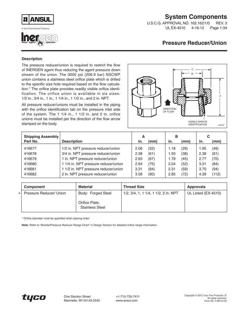
The pressure reducer/union is required to restrict the flowof INERGEN agent thus reducing the agent pressure downstream of the union. The 3000 psi (206.9 bar) NSCWPunion contains a stainless steel orifice plate which is drilledto the specific size hole required based on the flow calcula-tion.* The orifice plate provides readily visible orifice identi-fication. The orifice union is available in six sizes:1/2 in., 3/4 in., 1 in., 1 1/4 in., 1 1/2 in., and 2 in. NPT.
All pressure reducer/unions must be installed in the pipingwith the orifice identification tab on the pressure inlet sideof the system. The 1 1/4 in., 1 1/2 in. and 2 in. orificeunions must be installed per the direction of the flow arrowstamped on the body.
Pressure Reducer/Union
Shipping Assembly A B CPart No. Description in. (mm) in. (mm) in. (mm)
416677 1/2 in. NPT pressure reducer/union 2.06 (52) 1.18 (29) 1.95 (49)416678 3/4 in. NPT pressure reducer/union 2.38 (61) 1.50 (38) 2.38 (61)416679 1 in. NPT pressure reducer/union 2.63 (67) 1.78 (45) 2.77 (70)416680 1 1/4 in. NPT pressure reducer/union 2.94 (75) 2.04 (52) 3.31 (84)416681 1 1/2 in. NPT pressure reducer/union 3.31 (84) 2.31 (59) 3.70 (94)416682 2 in. NPT pressure reducer/union 3.56 (90) 2.85 (72) 4.39 (112)
Component Material Thread Size Approvals
Pressure Reducer/ Union Body: Forged Steel 1/2, 3/4, 1, 1 1/4, 1 1/2, 2 in. NPT UL Listed (EX-4510)
Orifice Plate:Stainless Steel
* Orifice diameter must be specified when placing order.
Note: Refer to “Nozzle/Pressure Reducer Range Chart” in Design Section for detailed orifice range information.
VISIBLE ORIFICEIDENTIFICATION 002197
DIRECTIONOF FLOW
C
A
B
Copyright © 2012 Tyco Fire Products LP.All rights reserved.
Form No. F-98112-03
One Stanton Street +1-715-735-7411Marinette, WI 54143-2542 www.ansul.com

System ComponentsU.S.C.G. APPROVAL NO. 162.162/1/0 REV. 3
UL EX-4510 4-16-12 Page 1-35
Description
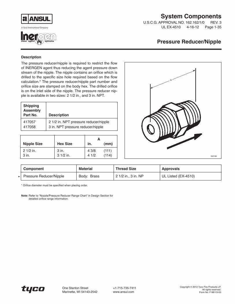
The pressure reducer/nipple is required to restrict the flowof INERGEN agent thus reducing the agent pressure downstream of the nipple. The nipple contains an orifice which isdrilled to the specific size hole required based on the flowcalculation.* The pressure reducer/nipple part number andorifice size are stamped on the body hex. The drilled orificeis on the inlet side of the nipple. The pressure reducer nip-ple is available in two sizes: 2 1/2 in., and 3 in. NPT.
* Orifice diameter must be specified when placing order.
Note: Refer to “Nozzle/Pressure Reducer Range Chart” in Design Section fordetailed orifice range information.
Pressure Reducer/Nipple
ShippingAssemblyPart No. Description
417057 2 1/2 in. NPT pressure reducer/nipple417058 3 in. NPT pressure reducer/nipple
ANipple Size Hex Size in. (mm)
2 1/2 in. 3 in. 4 3/8 (111)3 in. 3 1/2 in. 4 1/2 (114)
Component Material Thread Size Approvals
Pressure Reducer/Nipple Body: Brass 2 1/2 in., 3 in. NP UL Listed (EX-4510)
A
002198
Copyright © 2012 Tyco Fire Products LP.All rights reserved.
Form No. F-98113-03
One Stanton Street +1-715-735-7411Marinette, WI 54143-2542 www.ansul.com


System ComponentsU.S.C.G. APPROVAL NO. 162.162/1/0 REV. 3
UL EX-4510 4-16-12 Page 1-36a
Description
The flanged pressure reducer assembly is required torestrict the flow of INERGEN agent thus reducing the agentpressure down stream of the pressure reducer. The flangedpressure reducer assembly contains a stainless steel ori-fice plate which is drilled to the specific size hole requiredbased on the flow calculation.* The orifice plate providesreadily visible orifice identification. The flanged pressurereducer assembly is available in three sizes; 2 1/2, 3, and 4in. Each size is available in threaded, slip-on, and weldneck flange.
All orifice plates must be installed in the piping system withthe orifice identification information on the tab facing thepressure inlet side of the system.
* Orifice diameter must be specified when placing order.
Note: Refer to “Nozzle/Pressure Reducer Range Chart” in Design Section fordetailed orifice range information.
Flanged Pressure Reducer
ShippingAssembly EPart No. Description A B C D (8 Places)426823 2 1/2 in Threaded 4.23 in. 7.50 in. 9.70 in. 5.88 in. 0.88 in.
(107 mm) (191 mm) (246 mm) (149 mm) (22 mm)
426824 3 in. Threaded 4.10 in. 8.25 in. 10.46 in. 6.63 in. 0.88 in.(104 mm) (209 mm) (266 mm) (168 mm) (22 mm)
426825 4 in. Threaded 4.73 in. 10.75 in. 12.59 in. 8.50 in. 1.00 in.(120 mm) (273 mm) (319 mm) (216 mm) (25 mm)
426847 2 1/2 in. Slip-on 4.24 in. 7.50 in. 9.70 in. 5.88 in. 0.88 in.(108 mm) (191 mm) (246 mm) (149 mm) (22 mm)
426848 3 in. Slip-on 4.60 in. 8.25 in. 10.46 in. 6.63 in. 0.88 in.(117 mm) (209 mm) (266 mm) (168 mm) (22 mm)
426849 4 in. Slip-on 5.24 in. 10.75 in. 12.59 in. 8.50 in. 1.00 in.(133 mm) (273 mm) (319 mm) (216 mm) (25 mm)
426853 2 1/2 in. Weld Neck 7.23 in. 7.50 in. 9.70 in. 5.88 in. 0.88 in.(184 mm) (191 mm) (246 mm) (149 mm) (22 mm)
426854 3 in. Weld Neck 7.48 in. 8.25 in. 10.46 in. 6.63 in. 0.88 in.(189 mm) (209 mm) (266 mm) (168 mm) (22 mm)
426855 4 in. Weld Neck 8.98 in. 10.75 in. 12.59 in. 8.50 in. 1.00 in.(228 mm) (273 mm) (319 mm) (216 mm) (25 mm)
Component Material Approvals
Flange Forged Steel UL Listed (EX-4510)Flange Gasket Stainless SteelOrifice Plate Stainless SteelBolts Plated Steel,
Grade 5

Threaded
A
003655
Slip-On
A
003656
Weld Neck
A
003653
C
B003654
D
E
System ComponentsU.S.C.G. APPROVAL NO. 162.162/1/0 REV. 3UL EX-4510 4-16-12 Page 1-36b
Copyright © 2012 Tyco Fire Products LP.All rights reserved.
Form No. F-99067-03
One Stanton Street +1-715-735-7411Marinette, WI 54143-2542 www.ansul.com
System ComponentsU.S.C.G. APPROVAL NO. 162.162/1/0 REV. 3
UL EX-4510 4-16-12 Page 1-37
Description
Orifice plate shipping assemblies are available as replace-ment plates. Replacement plates may be required in situa-tions where the piping and pressure reducer size can staythe same but because of some hazard change, the size ofthe orifice in the pressure reducer must change.
The orifice size must be specified when ordering the orificeplate.
Note: Replacement orifice plates for orifice nipples are not available as the plateis a permanent fixture of the part.
Note: Refer to “Nozzle/Pressure Reducer Range Chart” in Design Section fordetailed orifice range information.
Orifice Plate
Part No. Description
418095 1/2 in. Replacement Orifice Plate418096 3/4 in. Replacement Orifice Plate418097 1 in. Replacement Orifice Plate418098 1 1/4 in. Replacement Orifice Plate418099 1 1/2 in. Replacement Orifice Plate418100 2 in. Replacement Orifice Plate426984 2 1/2 in. Replacement Orifice Plate426985 3 in. Replacement Orifice Plate426986 4 in. Replacement Orifice Plate
Copyright © 2012 Tyco Fire Products LP.All rights reserved.
Form No. F-98068-03
One Stanton Street +1-715-735-7411Marinette, WI 54143-2542 www.ansul.com

System ComponentsU.S.C.G. APPROVAL NO. 162.162/1/0 REV. 3
UL EX-4510 4-16-12 Page 1-38
Description
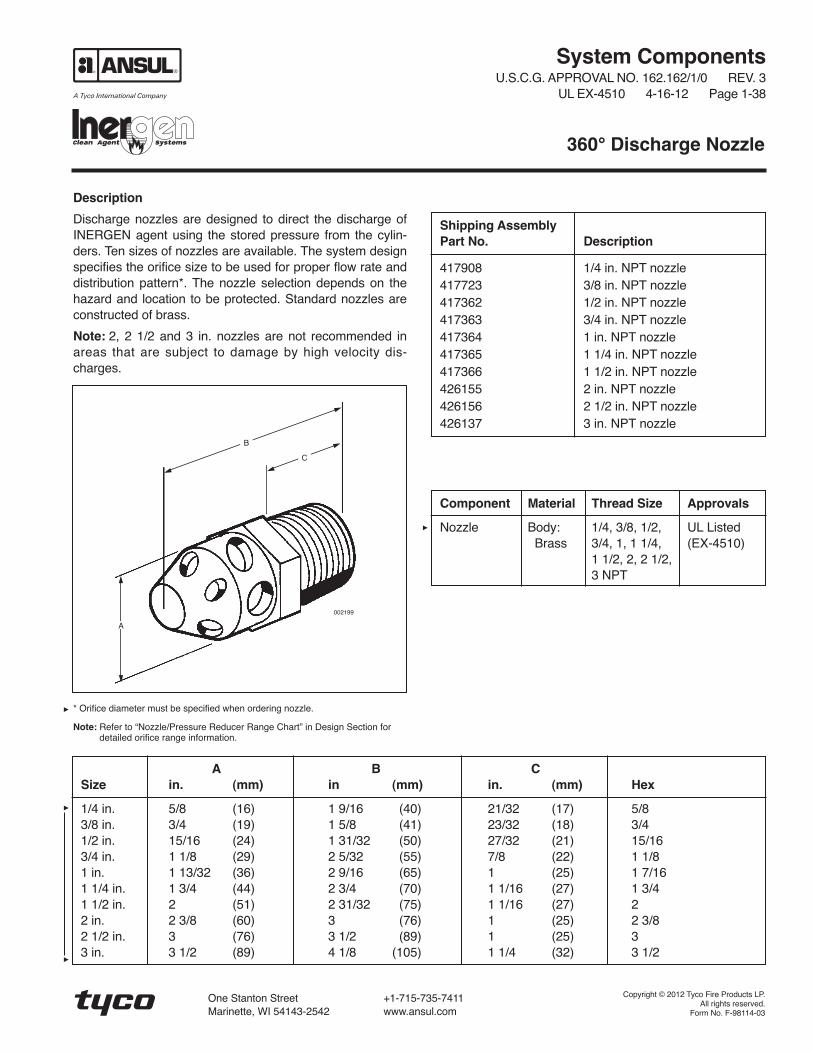
Discharge nozzles are designed to direct the discharge ofINERGEN agent using the stored pressure from the cylin-ders. Ten sizes of nozzles are available. The system designspecifies the orifice size to be used for proper flow rate anddistribution pattern*. The nozzle selection depends on thehazard and location to be protected. Standard nozzles areconstructed of brass.
Note: 2, 2 1/2 and 3 in. nozzles are not recommended inareas that are subject to damage by high velocity dis-charges.
* Orifice diameter must be specified when ordering nozzle.
Note: Refer to “Nozzle/Pressure Reducer Range Chart” in Design Section fordetailed orifice range information.
360° Discharge Nozzle
Shipping AssemblyPart No. Description
417908 1/4 in. NPT nozzle417723 3/8 in. NPT nozzle417362 1/2 in. NPT nozzle417363 3/4 in. NPT nozzle417364 1 in. NPT nozzle417365 1 1/4 in. NPT nozzle417366 1 1/2 in. NPT nozzle426155 2 in. NPT nozzle426156 2 1/2 in. NPT nozzle426137 3 in. NPT nozzle
Component Material Thread Size Approvals
Nozzle Body: 1/4, 3/8, 1/2, UL ListedBrass 3/4, 1, 1 1/4, (EX-4510)
1 1/2, 2, 2 1/2,3 NPT
A B CSize in. (mm) in (mm) in. (mm) Hex
1/4 in. 5/8 (16) 1 9/16 (40) 21/32 (17) 5/83/8 in. 3/4 (19) 1 5/8 (41) 23/32 (18) 3/41/2 in. 15/16 (24) 1 31/32 (50) 27/32 (21) 15/163/4 in. 1 1/8 (29) 2 5/32 (55) 7/8 (22) 1 1/81 in. 1 13/32 (36) 2 9/16 (65) 1 (25) 1 7/161 1/4 in. 1 3/4 (44) 2 3/4 (70) 1 1/16 (27) 1 3/41 1/2 in. 2 (51) 2 31/32 (75) 1 1/16 (27) 22 in. 2 3/8 (60) 3 (76) 1 (25) 2 3/82 1/2 in. 3 (76) 3 1/2 (89) 1 (25) 33 in. 3 1/2 (89) 4 1/8 (105) 1 1/4 (32) 3 1/2
B
C
A
002199
Copyright © 2012 Tyco Fire Products LP.All rights reserved.
Form No. F-98114-03
One Stanton Street +1-715-735-7411Marinette, WI 54143-2542 www.ansul.com


System ComponentsU.S.C.G. APPROVAL NO. 162.162/1/0 REV. 3
UL EX-4510 4-16-12 Page 1-39
Description
Discharge nozzles are designed to direct the discharge ofINERGEN agent using the stored pressure from the cylin-ders. Ten sizes of nozzles are available. The system designspecifies the orifice size to be used for proper flow rate anddistribution pattern*. The nozzle selection depends on thehazard and location to be protected. The 180° nozzle iscommonly used when nozzle placement is at or near thebulkhead. Standard nozzles are constructed of brass.
An index mark is stamped on the bottom of the nozzle toindicate aiming direction.
* Orifice diameter must be specified when ordering nozzle.
Note: Refer to “Nozzle/Pressure Reducer Range Chart” in Design Section fordetailed orifice range information.
180° Discharge Nozzle
Shipping AssemblyPart No. Description
426138 1/4 in. NPT nozzle426139 3/8 in. NPT nozzle426140 1/2 in. NPT nozzle426141 3/4 in. NPT nozzle426142 1 in. NPT nozzle426143 1 1/4 in. NPT nozzle426157 1 1/2 in. NPT nozzle426144 2 in. NPT nozzle426145 2 1/2 in. NPT nozzle426146 3 in. NPT nozzle
002743
22.5°
A
Component Material Thread Size Approvals
Nozzle Body: 1/4, 3/8, 1/2, UL ListedBrass 3/4, 1, 1 1/4, (EX-4510)
1 1/2, 2, 2 1/2,3 NPT
C
002742
B
INDEXMARK
A B CSize in. (mm) in (mm) in. (mm) Hex
1/4 in. 5/8 (16) 1 9/16 (40) 21/32 (17) 5/83/8 in. 3/4 (19) 1 5/8 (41) 23/32 (18) 3/41/2 in. 15/16 (24) 1 31/32 (50) 27/32 (21) 15/163/4 in. 1 1/8 (29) 2 5/32 (55) 7/8 (22) 1 1/81 in. 1 13/32 (36) 2 9/16 (65) 1 (25) 1 7/161 1/4 in. 1 3/4 (44) 2 3/4 (70) 1 1/16 (27) 1 3/41 1/2 in. 2 (51) 2 31/32 (75) 1 1/16 (27) 22 in. 2 3/8 (60) 3 (76) 1 (25) 2 3/82 1/2 in. 3 (76) 3 1/2 (89) 1 (25) 33 in. 3 1/2 (89) 4 1/8 (105) 1 1/4 (32) 3 1/2
Copyright © 2012 Tyco Fire Products LP.All rights reserved.
Form No. F-98115-03
One Stanton Street +1-715-735-7411Marinette, WI 54143-2542 www.ansul.com


Pressure-Operated Siren
System ComponentsU.S.C.G. APPROVAL NO. 162.162/1/0 REV. 2
UL EX-4510 4-16-12 Page 1-40
Description
The pressure-operated siren is used to warn personnel of asystem discharge. The siren is operated with the nitrogenpressure from the pilot cylinder. The siren will operate atthe start of the INERGEN system actuation and willcontinue through most of the discharge time. A pipe hangeror bracket must be installed within one foot of the siren.
The design requirements are as follows:
Maximum Pipe Length:
– 240 ft (73.2 m) of 3/4 in. Schedule 40 pipe
– 430 ft (131.1 m) of 1/2 in. Schedule 40 pipe
– 675 ft (205.7 m) of 3/8 in. Schedule 40 pipe
• Maximum Sirens: 5
• Maximum Elbows: 30Component Material Approvals
Siren Body: Brass UL EX-4510; Listed
Grille: Steel for use with FM
Screen: Stainless Approved systems
Steel
Shipping AssemblyPart No. Description
437616 Pressure-operated siren
1/4 IN.NPTINLET
6.25 IN.(159 mm)
5.60 IN.(142 mm)
008806
0.34 IN. (9 mm)DIA. HOLE (2)
3.42 IN.(87 mm)
5.25 IN.(133 mm)
Copyright © 2012 Tyco Fire Products LP.All rights reserved.
Form No. F-2012070
One Stanton Street +1-715-735-7411Marinette, WI 54143-2542 www.ansul.com


Description
The pressure switch is operated by the INERGEN agentpressure when the system is discharged. The pressureswitch can be used to open or close electrical circuits toshut down equipment (single or 3-phase) or turn on lights oralarms. The housing is constructed of 16 ga. steel, paintedred, and is rated IP65 for dust and water ingress. The 3/8in. NPT brass pressure inlet is used to connect the pres-sure switch to the suppression system.
Minimum operating pressure is 50 psi (3.5 bar).
System ComponentsU.S.C.G. APPROVAL NO. 162.162/1/0 REV. 3
UL EX-4510 4-16-12 Page 1-41
Pressure Switch – 3PDT
Shipping AssemblyPart No. Description
437900 Pressure switch – 3PDT
Component Material Thread Size/Type Electrical Rating Approvals
Pressure Switch Switch: Nickel-plated Brass Conduit Inlets: 10A, 250 VAC UL Listed– 3PDT Housing/Cover: C.R. 16 ga steel 3/4 in. and 1/2 in. 15A, 125 VAC (EX-4510)
Plunger: Stainless Steel Pressure Inlet: 3/4 HP, 250 VAC
Pressure Port: C37700 Brass 3/8 in. NPT Female 1-, 2-, and 3-phase
008979
6.0 IN.(152 mm)
4.45 IN.(113 mm)
5.25 IN.(133 mm)
2.75 IN.(70 mm)
0089783.83 IN.(97 mm)
4.45 IN.(113 mm)
4.51 IN.(115 mm)
Copyright © 2012 Tyco Fire Products LP.All rights reserved.
Form No. F-2012058
One Stanton Street +1-715-735-7411Marinette, WI 54143-2542 www.ansul.com


Description
The pressure switch is operated by the INERGEN agentpressure when the system is discharged. The pressureswitch can be used to open or close electrical circuits toeither shut down equipment or ventilation systems and turnon lights or alarms. The double pole, double throw (DPDT)pressure switch is constructed with an explosion-proof hous-ing suitable for hazardous environments. A 1/4 in. NPT pres-sure inlet is used to connect the 1/4 in. pipe from the INERGEN system.
Note: Suitable for hazardous locations, Class I, Division I, Groups C, D,and Class II, Division I, Groups E, F, G.
The pressure switch can be installed either before or afterthe pressure reducer in the distribution piping.
Minimum operating pressure is 100 psi (6.9 bar).
System ComponentsU.S.C.G. APPROVAL NO. 162.162/1/0 REV. 2
UL EX-4510 4-16-12 Page 1-42
Pressure Switch DPDT – Explosion-Proof
Shipping AssemblyPart No. Description
43241 Pressure switch – DPDT
Component Material Thread Size/Type Electrical Rating Approvals
Pressure Switch Housing: Conduit Inlet: 3/4 in. NPT Female 10A - 125 VAC UL Listed (EX-4510)DPDT Malleable Iron Pressure Inlet: 1/4 in. NPT Female 5A - 250 VAC
1/4 IN. PIPE CONNECTIONTO INERGEN SYSTEM
1/4 IN. UNION
3/8 IN. X 1/4 IN. BUSHING
NAMEPLATE
2 11/32 IN.MOUNTING HOLES
7 7/8 IN.(200 mm)
6 1/2 IN.(165 mm)
5 3/16 IN.(147 mm)
5 1/8 IN.(130 mm)
3 9/16 IN.(91 mm)
5 5/8 IN.(142 mm)
2 5/8 IN.(66 mm)
3/4 IN.CONDUITOUTLET
000455000454
3/4 IN.CONDUITOUTLET
Copyright © 2012 Tyco Fire Products LP.All rights reserved.
Form No. F-98118-02
One Stanton Street +1-715-735-7411Marinette, WI 54143-2542 www.ansul.com


System ComponentsU.S.C.G. APPROVAL NO. 162.162/1/0 REV. 2
UL EX-4510 4-16-12 Page 1-43
THIS PAGE INTENTIONALLYLEFT BLANK


System ComponentsU.S.C.G. APPROVAL NO. 162.162/1/0 REV. 2
UL EX-4510 4-16-12 Page 1-44
Description
The pressure trip is connected to the actuation or dischargeline of an INERGEN system. By either pneumatic or manu-al actuation, the pressure trip can release spring or weightpowered devices to close ventilation dampers, open fueldump valves, close fire dampers or close fuel supplyvalves. The pressure trip is constructed of brass with two1/4 in. NPT fittings for connection to discharge or actuationlines. The link on the pressure switch is released eitherpneumatically, by agent discharge pressure; or manually,
by use of the pull ring. The link then releases the devicewhich performs the auxiliary functions.
Note: Operating pressure must be a minimum of 75 psi(5.2 bar) with a maximum load of 70 lb (31.8 kg).
Pressure Trip
Shipping AssemblyPart No. Description
5156 Pressure trip
Component Material Thread Size/Type Approvals
Pressure Trip Brass 1/4 in. NPT Female UL Listed (EX-4510)
3 3/4 IN.(95 mm)
1/4 IN. NPT
000452
3 IN.(76 mm)
Copyright © 2012 Tyco Fire Products LP.All rights reserved.
Form No. F-98120-02
One Stanton Street +1-715-735-7411Marinette, WI 54143-2542 www.ansul.com


System ComponentsU.S.C.G. APPROVAL NO. 162.162/1/0 REV. 2
UL EX-4510 4-16-12 Page 1-45a
Description
The cylinder bracketing is designed to rigidly support theinstalled INERGEN agent cylinders. The bracketing compo-nents are constructed of heavy structural steel. Bracketassemblies are available in modules for two to six cylindersand can also be connected together for any combinationover six. Bracketing can be assembled to support singlerow, double row or back-to-back rows of cylinders.Bracketing components are painted with a red enamel
coating. Uprights and back frame assemblies can be boltedor welded together, which ever makes the installation moreconvenient.
Cylinder Bracketing
Component Material Approvals
Bracketing Steel UL Listed (EX-4510)
ShippingAssemblyPart No. Description
45120 200 ft3 (5.7 m3) cylinder strap (single cylinder)45244 200 ft3 (5.7 m3) cylinder channel with nuts and bolts (single cylinder)45121 250 ft3 (7.1 m3) cylinder strap (single cylinder)45261 250 ft3 (7.1 m3) cylinder channel with nuts and bolts (single cylinder)45122 350 ft3 (9.9 m3) cylinder strap (single cylinder)45245 350 ft3 (9.9 m3) cylinder channel with nuts and bolts (single cylinder)427704 435 ft3 (12.3 m3) cylinder strap with padding (single cylinder)427705 435 ft3 (12.3 m3) cylinder channel with nuts, bolts, saddle, and padding (single cylinder)79638 Back frame assembly (2 cylinder)79639 Back frame assembly (3 cylinder)79640 Back frame assembly (4 cylinder)79641 Back frame assembly (5 cylinder)79642 Back frame assembly (6 cylinder)73257 Upright for 200, 250, 350, and 435 ft3 cylinders (used either for right side, left side or center (center upright
required when connecting seven or more cylinders in a row))73553 Single row or back-to-back row bracket foot (left side)73554 Single row or back-to-back row bracket foot (right side)73555 Double row bracket foot (left side)73556 Double row bracket foot (right side)418508 Center upright foot79413 Connector (required to hook together back frames for seven or more cylinders)73250 10.5 in. (267 mm) carriage bolt with lockwasher and nut (for single row 200 ft3 (5.7 m3) cylinders)73251 11 in (279 mm) carriage bolt with lockwasher and nut (for single row 250 ft3 (7.1 m3) cylinders)73252 12.5 in. (318 mm) carriage bolt with lockwasher and nut (for single row 350 ft3 (9.9 m3) and 425 ft3
(12.0 m3) cylinders)418502 13 in. (330 mm) carriage bolt with lockwasher and nut (for single row 435 ft3 (12.3 m3) cylinders)73253 21 in. (533 mm) carriage bolt with lockwasher and nut (for double row 200 ft3 (5.7 m3) cylinders)73254 22 in. (559 mm) carriage bolt with lockwasher and nut (for double row 250 ft3 (7.1 m3) cylinders)73255 26 in. (660 mm) carriage bolt with lockwasher and nut (for double row 350 ft3 (9.9 m3) and 425 ft3
(12.0 m3) cylinders)418503 27 in. (686 mm) carriage bolt with lockwasher and nut (for double row 435 ft3 (12.3 m3) cylinders)

Multi-Cylinder Single Cylinder
UPRIGHT
BACK FRAME*
CYLINDER CLAMP*
CARRIAGE BOLTWITH NUT ANDLOCKWASHER
RIGHTBRACKET FOOT
LEFTBRACKET FOOT
CHANNEL
004386
CLAMP
* Note: Two sets of cylinder clamps and back frame assemblies are required to secure cylinders.
73091 Cylinder clamp (2 cylinders)73092 Cylinder clamp (3 cylinders)71683 Weigh rail support – single row71682 Weigh rail support – double row71684 Weigh rail support – back-to-back rows423027 Weigh rail support back-to-back double row
ShippingAssemblyPart No. Description
System ComponentsU.S.C.G. APPROVAL NO. 162.162/1/0 REV. 2UL EX-4510 4-16-12 Page 1-45b
Copyright © 2012 Tyco Fire Products LP.All rights reserved.
Form No. F-98116-02
One Stanton Street +1-715-735-7411Marinette, WI 54143-2542 www.ansul.com

System ComponentsU.S.C.G. APPROVAL NO. 162.162/1/0 REV. 2
UL EX-4510 4-16-12 Page 1-46
Description
The Pressure Test Assembly (Part No. 423923) is requiredto properly perform the semi-annual pressure check perNFPA 2001. The pressure test assembly consists of a cali-brated gauge, adaptor, and handwheel. The assembly isattached to the fill port of the INERGEN valve. As the hand-wheel is turned in, the fill port is opened and the pressure isread on the gauge. After verifying the pressure in the cylin-der, the handwheel is turned out, closing the fill port andventing the pressure. With the pressure vented, the assem-bly can be removed.
Pressure Test Assembly
Shipping AssemblyPart No. Description
423923 Pressure Test Assembly
Component Material Approvals
Handwheel Cast Zinc Alloy UL Listed (EX-4510)Body BrassAdaptor BrassGauge Stainless
Steel CaseLaminatedSafetyGlass Lens
002744
Copyright © 2012 Tyco Fire Products LP.All rights reserved.
Form No. F-98121-02
One Stanton Street +1-715-735-7411Marinette, WI 54143-2542 www.ansul.com


System ComponentsU.S.C.G. APPROVAL NO. 162.162/1/0 REV. 2
UL EX-4510 4-16-12 Page 1-47
Description
The operating instruction plate is available for mounting atthe pull box location to instruct personnel on system actua-tion. The operating plate is furnished with four mountingholes for ease of installation. The plate is constructed ofaluminum.
Operating Instructions Plate – Pull Cable Actuation
Shipping AssemblyPart No. Description
41915 Operating Instructions – PullCable Actuation
Component Material Mounting Hole Size Approvals
Operating Instructions Aluminum 1/4 in. (64 mm) UL Listed (EX-4510)Instructions –Pull Cable Actuation
FIRE SUPPRESSION SYSTEMTO OPERATE:
1. BE SURE ALL DOORS OR OTHER OPENINGS ARESECURED IN PROTECTED SPACE
2. BREAK GLASS AND PULL HANDLE HARD IN PULLBOX MARKED “VALVE RELEASE”
3. BREAK GLASS AND PULL HANDLE HARD IN PULLBOX MARKED “CYLINDER RELEASE”
4. THIS SOUNDS ALARM. DISCHARGE OF GAS ISDELAYED SECONDS TO ALLOW PERSONNELTO CLEAR FIRE AREA
8 IN.(203 mm)
7.5 IN.(191 mm)
5 IN.(127 mm)
LABEL NO. 41915
002748
4.5 IN.(114 mm)
.22 Ø – 4 HOLES
Copyright © 2012 Tyco Fire Products LP.All rights reserved.
Form No. F-98127-02
One Stanton Street +1-715-735-7411Marinette, WI 54143-2542 www.ansul.com

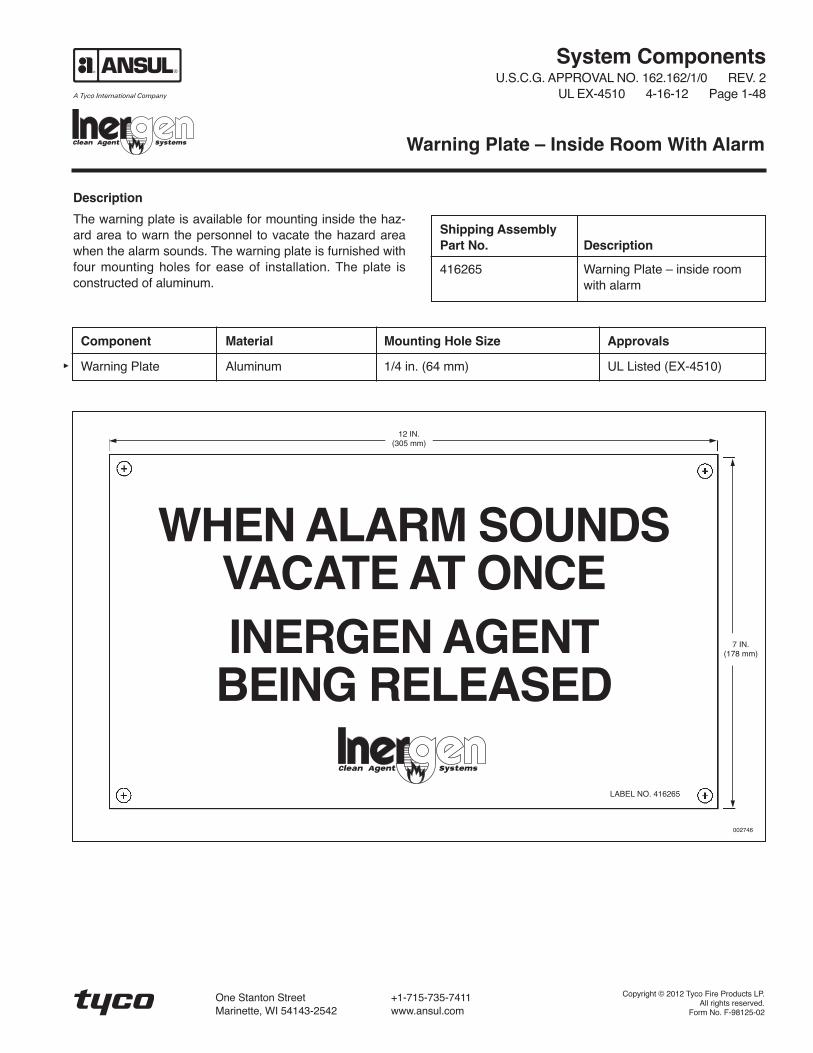
System ComponentsU.S.C.G. APPROVAL NO. 162.162/1/0 REV. 2
UL EX-4510 4-16-12 Page 1-48
Description
The warning plate is available for mounting inside the haz-ard area to warn the personnel to vacate the hazard areawhen the alarm sounds. The warning plate is furnished withfour mounting holes for ease of installation. The plate isconstructed of aluminum.
Warning Plate – Inside Room With Alarm
Shipping AssemblyPart No. Description
416265 Warning Plate – inside roomwith alarm
Component Material Mounting Hole Size Approvals
Warning Plate Aluminum 1/4 in. (64 mm) UL Listed (EX-4510)
WHEN ALARM SOUNDSVACATE AT ONCEINERGEN AGENT
BEING RELEASED
12 IN.(305 mm)
7 IN.(178 mm)
LABEL NO. 416265
002746
Copyright © 2012 Tyco Fire Products LP.All rights reserved.
Form No. F-98125-02
One Stanton Street +1-715-735-7411Marinette, WI 54143-2542 www.ansul.com


System ComponentsU.S.C.G. APPROVAL NO. 162.162/1/0 REV. 2
UL EX-4510 4-16-12 Page 1-49
Description
The warning plate is available for mounting outside the haz-ard area to warn the personnel that the space is protectedby an INERGEN system and no one should enter after adischarge without being properly protected. The warningplate is furnished with four mounting holes for ease ofinstallation.
Warning Plate – Outside Room Without Alarm
Shipping AssemblyPart No. Description
416266 Warning Plate – outsideroom
Component Material Mounting Hole Size Approvals
Warning Plate Stainless Steel 7/32 in. (56 mm) UL Listed (EX-4510)
WARNINGTHIS SPACE IS PROTECTED BY AN INERGENFIRE SUPPRESSION SYSTEM.
WHEN SYSTEM IS DISCHARGED AS A RESULTOF FIRE, CAUTION MUST BE TAKEN TO AVOIDEXPOSURE TO PRODUCTS OF COMBUSTION.
DO NOT ENTER WITHOUT APPROVED SELF-CONTAINED BREATHING APPARATUS ORUNTIL VENTILATION HAS BEEN OPERATEDFOR AT LEAST 15 MINUTES.
8 IN.(203 mm)
7 IN.(178 mm)
LABEL NO. 416266
002747
!
Copyright © 2012 Tyco Fire Products LP.All rights reserved.
Form No. F-98126-02
One Stanton Street +1-715-735-7411Marinette, WI 54143-2542 www.ansul.com

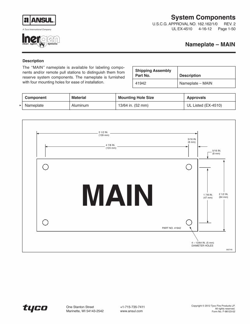
System ComponentsU.S.C.G. APPROVAL NO. 162.162/1/0 REV. 2
UL EX-4510 4-16-12 Page 1-50
Description
The ʻʻMAINʼʼ nameplate is available for labeling compo-nents and/or remote pull stations to distinguish them fromreserve system components. The nameplate is furnishedwith four mounting holes for ease of installation.
Nameplate – MAIN
Shipping AssemblyPart No. Description
41942 Nameplate – MAIN
Component Material Mounting Hole Size Approvals
Nameplate Aluminum 13/64 in. (52 mm) UL Listed (EX-4510)
MAIN
5 1/2 IN.(139 mm)
4 7/8 IN.(124 mm)
1 7/8 IN.(47 mm)
2 1/2 IN.(64 mm)
5/16 IN.(8 mm)
5/16 IN.(8 mm)
PART NO. 41942
4 – 13/64 IN. (5 mm)DIAMETER HOLES
002745
Copyright © 2012 Tyco Fire Products LP.All rights reserved.
Form No. F-98123-02
One Stanton Street +1-715-735-7411Marinette, WI 54143-2542 www.ansul.com


System ComponentsU.S.C.G. APPROVAL NO. 162.162/1/0 REV. 2
UL EX-4510 4-16-12 Page 1-51
Description
The ʻʻRESERVEʼʼ nameplate is available for labeling com-ponents and/or remote pull stations to distinguish themfrom main system components. The nameplate is furnishedwith four mounting holes for ease of installation.
Nameplate – RESERVE
Shipping AssemblyPart No. Description
41943 Nameplate – RESERVE
Component Material Mounting Hole Size Approvals
Nameplate Aluminum 13/64 in. (52 mm) UL Listed (EX-4510)
RESERVE
5 1/2 IN.(139 mm)
4 7/8 IN.(124 mm)
1 7/8 IN.(48 mm)
2 1/2 IN.(64 mm)
5/16 IN.(8 mm)
5/16 IN.(8 mm)
PART NO. 41943
4 – 13/64 IN. (52 mm)DIAMETER HOLES
002745
Copyright © 2012 Tyco Fire Products LP.All rights reserved.
Form No. F-98124-02
One Stanton Street +1-715-735-7411Marinette, WI 54143-2542 www.ansul.com