Embed Size (px)
Citation preview

USE AND MAINTENANCEUSO E MANUTENZIONEUTILISATION ET ENTRETIENBETRIEB UND WARTUNGUSO Y MANTENIMIENTO
MARINE ENGINES
NEF SERIES ELECTRONIC INJECTION SYSTEM
Publication edited byMarketing - Adv. & PromotionPrint L31900008 - 10/05
1
EN
GL
ISH
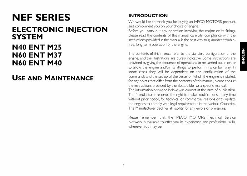
NEF SERIESELECTRONIC INJECTION SYSTEM N40 ENT M25N60 ENT M37N60 ENT M40
USE AND MAINTENANCE
INTRODUCTIONWe would like to thank you for buying an IVECO MOTORS product,and compliment you on your choice of engine.Before you carry out any operation involving the engine or its fittings,please read the contents of this manual carefully; compliance with theinstructions provided in the manual is the best way to guarantee trouble-free, long term operation of the engine.
The contents of this manual refer to the standard configuration of theengine, and the illustrations are purely indicative. Some instructions areprovided by giving the sequence of operations to be carried out in orderto allow the engine and/or its fittings to perform in a certain way. Insome cases they will be dependent on the configuration of thecommands and the set-up of the vessel on which the engine is installed;for any points that differ from the contents of this manual, please consultthe instructions provided by the Boatbuilder or a specific manual.The information provided below was current at the date of publication.The Manufacturer reserves the right to make modifications at any timewithout prior notice, for technical or commercial reasons or to updatethe engines to comply with legal requirements in the various Countries.The Manufacturer declines all liability for any errors or omissions.
Please remember that the IVECO MOTORS Technical ServiceNetwork is available to offer you its experience and professional skills,wherever you may be.
2
CONTENTS PageGENERAL INFORMATION . . . . . . . . . . . . . . . . . . . . . . . . . . . . . .3Guarantee . . . . . . . . . . . . . . . . . . . . . . . . . . . . . . . . . . . . . . . . . . . . . .3Spare Parts . . . . . . . . . . . . . . . . . . . . . . . . . . . . . . . . . . . . . . . . . . . . .3Liability . . . . . . . . . . . . . . . . . . . . . . . . . . . . . . . . . . . . . . . . . . . . . . . . .3Safety . . . . . . . . . . . . . . . . . . . . . . . . . . . . . . . . . . . . . . . . . . . . . . . . . .3Engine technical data N40 ENT M25. . . . . . . . . . . . . . . . . . . . . . . .4Engine technical data N60 ENT M37/M40 . . . . . . . . . . . . . . . . . . .6Signs . . . . . . . . . . . . . . . . . . . . . . . . . . . . . . . . . . . . . . . . . . . . . . . . . . .8USE . . . . . . . . . . . . . . . . . . . . . . . . . . . . . . . . . . . . . . . . . . . . . . . . . . . .9Preliminary checks. . . . . . . . . . . . . . . . . . . . . . . . . . . . . . . . . . . . . . . .9Starting and stopping the engine . . . . . . . . . . . . . . . . . . . . . . . . . . . .9Starting and stopping the engine from the analogue control panel . . . . 10Recognising alarms . . . . . . . . . . . . . . . . . . . . . . . . . . . . . . . . . . . . . .13Starting and stopping the engine from the digital control panel .14Recognising alarms . . . . . . . . . . . . . . . . . . . . . . . . . . . . . . . . . . . . . .16Managing the engine from the Relay box . . . . . . . . . . . . . . . . . . .19Proper use of the engine . . . . . . . . . . . . . . . . . . . . . . . . . . . . . . . . .20Special warnings . . . . . . . . . . . . . . . . . . . . . . . . . . . . . . . . . . . . . . . .20Running in . . . . . . . . . . . . . . . . . . . . . . . . . . . . . . . . . . . . . . . . . . . . .21Refuelling . . . . . . . . . . . . . . . . . . . . . . . . . . . . . . . . . . . . . . . . . . . . . .22CONTROLS AND MAINTENANCE . . . . . . . . . . . . . . . . . . . . .23Maintenance personnel . . . . . . . . . . . . . . . . . . . . . . . . . . . . . . . . . .23Accident prevention . . . . . . . . . . . . . . . . . . . . . . . . . . . . . . . . . . . . .23Frequency . . . . . . . . . . . . . . . . . . . . . . . . . . . . . . . . . . . . . . . . . . . . .24Requirements . . . . . . . . . . . . . . . . . . . . . . . . . . . . . . . . . . . . . . . . . .26How to proceed. . . . . . . . . . . . . . . . . . . . . . . . . . . . . . . . . . . . . . . .26Moving the engine . . . . . . . . . . . . . . . . . . . . . . . . . . . . . . . . . . . . . .33Disposal of waste . . . . . . . . . . . . . . . . . . . . . . . . . . . . . . . . . . . . . . .33LONG PERIODS OF INACTIVITY . . . . . . . . . . . . . . . . . . . . . . .34Preparing the engine for a long period of inactivity . . . . . . . . . . .34Restarting the engine after a long period of inactivity . . . . . . . . .35ENGINE MALFUNCTIONS . . . . . . . . . . . . . . . . . . . . . . . . . . . . .36
Page
EMERGENCIES ON BOARD . . . . . . . . . . . . . . . . . . . . . . . . . . . .37IN APPENDIX . . . . . . . . . . . . . . . . . . . . . . . . . . . . . . . . . . . . . . . . . . .Oil viscosity level according to surrounding temperatures . . . . . . .
3
EN
GL
ISH
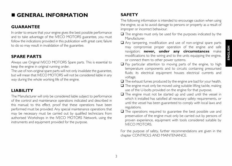
GENERAL INFORMATION
GUARANTEEIn order to ensure that your engine gives the best possible performanceand to take advantage of the IVECO MOTORS guarantee, you mustfollow the indications provided in this publication with great care; failureto do so may result in invalidation of the guarantee.
SPARE PARTSAlways use Original IVECO MOTORS Spare parts. This is essential tokeep the engine in original running order.The use of non-original spare parts will not only invalidate the guarantee,but will mean that IVECO MOTORS will not be considered liable in anyway during the whole working life of the engine.
LIABILITYThe Manufacturer will only be considered liable subject to performanceof the control and maintenance operations indicated and described inthis manual; to this effect, proof that these operations have beenperformed must be provided. Any special maintenance operations thatmay be necessary must be carried out by qualified technicians fromauthorised Workshops in the IVECO MOTORS Network, using theinstruments and equipment provided for the purpose.
SAFETYThe following information is intended to encourage caution when usingthe engine, so as to avoid damage to persons or property as a result ofimproper or incorrect behaviour.
The engines must only be used for the purposes indicated by theManufacturer.Any tampering, modification and use of non-original spare partsmay compromise proper operation of the engine and safenavigation; never, under any circumstances makemodifications to the wiring and to the units equipping the engine,or connect them to other power systems. Pay particular attention to moving parts of the engine, to hightemperature components and to circuits containing pressurisedfluids; its electrical equipment houses electrical currents andvoltage.The exhaust fumes produced by the engine are bad for your health.The engine must only be moved using suitable lifting tackle, makinguse of the U-bolts provided on the engine for that purpose.The engine must not be started up and used until the vessel inwhich it installed has satisfied all necessary safety requirements, oruntil the vessel has been guaranteed to comply with local laws andregulations.The operations required to guarantee the best possible use andpreservation of the engine must only be carried out by persons ofproven experience, equipment with tools considered suitable byIVECO MOTORS.
For the purpose of safety, further recommendations are given in thechapter CONTROLS AND MAINTENANCE.
4
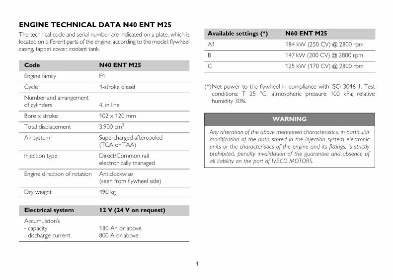
ENGINE TECHNICAL DATA N40 ENT M25The technical code and serial number are indicated on a plate, which islocated on different parts of the engine, according to the model: flywheelcasing, tappet cover, coolant tank.
(*)Net power to the flywheel in compliance with ISO 3046-1. Testconditions: T 25 °C; atmospheric pressure 100 kPa; relativehumidity 30%.
Code N40 ENT M25
Engine family F4
Cycle 4-stroke diesel
Number and arrangementof cylinders 4, in line
Bore x stroke 102 x 120 mm
Total displacement 3.900 cm3
Air system Supercharged aftercooled (TCA or TAA)
Injection type Direct/Common rail electronically managed
Engine direction of rotation Anticlockwise (seen from flywheel side)
Dry weight 490 kg
Electrical system 12 V (24 V on request)
Accumulator/s- capacity 180 Ah or above- discharge current 800 A or above
Available settings (*) N60 ENT M25
A1 184 kW (250 CV) @ 2800 rpm
B 147 kW (200 CV) @ 2800 rpm
C 125 kW (170 CV) @ 2800 rpm
WARNING
Any alteration of the above mentioned characteristics, in particularmodification of the data stored in the injection system electronicunits or the characteristics of the engine and its fittings, is strictlyprohibited, penalty invalidation of the guarantee and absence ofall liability on the part of IVECO MOTORS.
5
EN
GL
ISH
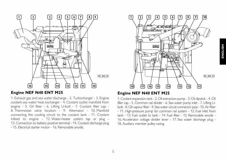
Engine NEF N40 ENT M25 1. Exhaust gas and sea water discharge - 2. Turbocharger - 3. Enginecoolant-sea water heat exchanger - 4. Coolant outlet manifold fromengine - 5. Oil filter - 6. Lifting U-bolt - 7. Coolant filler cap -8. Thermostat valve location - 9. Alternator - 10. Manifoldconnecting the cooling circuit to the coolant tank - 11. Coolantinfeed to engine - 12. Water-heater system tap or plug -13. Connection to battery positive terminal - 14. Coolant discharge plug- 15. Electrical starter motor - 16. Removable anode.
Engine NEF N40 ENT M251. Coolant expansion tank - 2. Oil extraction pump - 3. Oil dipstick - 4. Oilfiller cap - 5. Common rail divider - 6. Sea water pump inlet - 7. Lifting U-bolt - 8. Oil vapour filter - 9. Sea water circuit connector pipe - 10. Air filter- 11. High-pressure pump for common rail system - 12. Fuel inlet fromtank - 13. Fuel outlet to tank - 14. Fuel filter - 15. Removable anode -16. Accelerator voltage divider lever - 17. Sea water discharge plug -18. Auxiliary member pulley casing.
04_363_N 04_364_N
6
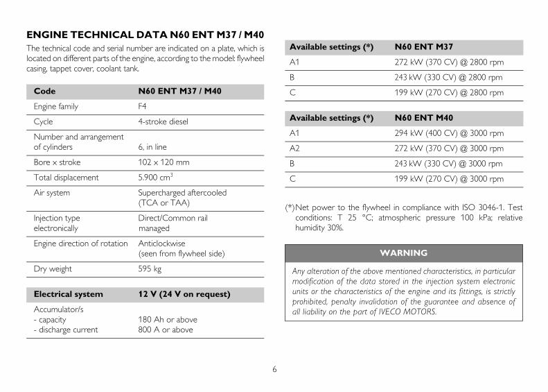
ENGINE TECHNICAL DATA N60 ENT M37 / M40The technical code and serial number are indicated on a plate, which islocated on different parts of the engine, according to the model: flywheelcasing, tappet cover, coolant tank.
(*)Net power to the flywheel in compliance with ISO 3046-1. Testconditions: T 25 °C; atmospheric pressure 100 kPa; relativehumidity 30%.
Code N60 ENT M37 / M40
Engine family F4
Cycle 4-stroke diesel
Number and arrangementof cylinders 6, in line
Bore x stroke 102 x 120 mm
Total displacement 5.900 cm3
Air system Supercharged aftercooled (TCA or TAA)
Injection type Direct/Common rail electronically managed
Engine direction of rotation Anticlockwise (seen from flywheel side)
Dry weight 595 kg
Electrical system 12 V (24 V on request)
Accumulator/s- capacity 180 Ah or above- discharge current 800 A or above
Available settings (*) N60 ENT M37
A1 272 kW (370 CV) @ 2800 rpm
B 243 kW (330 CV) @ 2800 rpm
C 199 kW (270 CV) @ 2800 rpm
Available settings (*) N60 ENT M40
A1 294 kW (400 CV) @ 3000 rpm
A2 272 kW (370 CV) @ 3000 rpm
B 243 kW (330 CV) @ 3000 rpm
C 199 kW (270 CV) @ 3000 rpm
WARNING
Any alteration of the above mentioned characteristics, in particularmodification of the data stored in the injection system electronicunits or the characteristics of the engine and its fittings, is strictlyprohibited, penalty invalidation of the guarantee and absence ofall liability on the part of IVECO MOTORS.
7
EN
GL
ISH
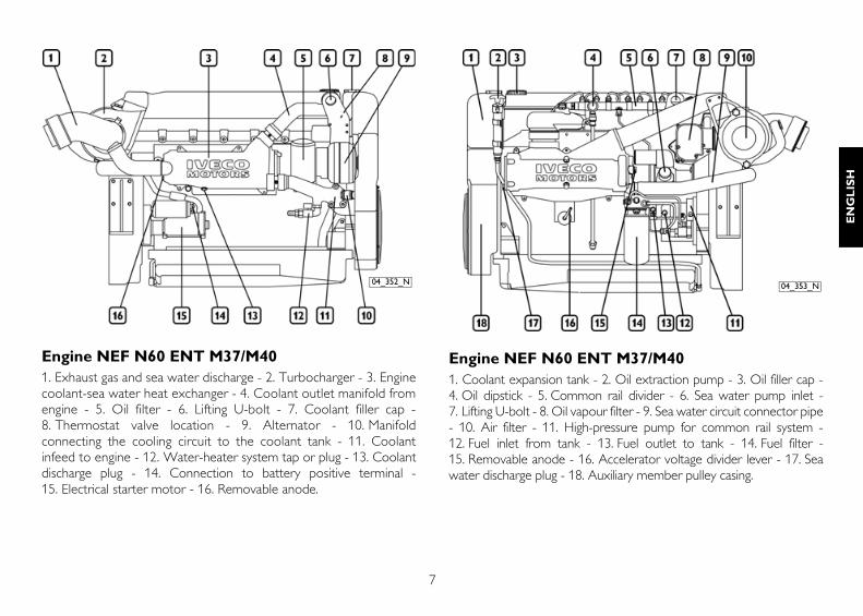
Engine NEF N60 ENT M37/M401. Exhaust gas and sea water discharge - 2. Turbocharger - 3. Enginecoolant-sea water heat exchanger - 4. Coolant outlet manifold fromengine - 5. Oil filter - 6. Lifting U-bolt - 7. Coolant filler cap -8. Thermostat valve location - 9. Alternator - 10. Manifoldconnecting the cooling circuit to the coolant tank - 11. Coolantinfeed to engine - 12. Water-heater system tap or plug - 13. Coolantdischarge plug - 14. Connection to battery positive terminal -15. Electrical starter motor - 16. Removable anode.
Engine NEF N60 ENT M37/M401. Coolant expansion tank - 2. Oil extraction pump - 3. Oil filler cap -4. Oil dipstick - 5. Common rail divider - 6. Sea water pump inlet -7. Lifting U-bolt - 8. Oil vapour filter - 9. Sea water circuit connector pipe- 10. Air filter - 11. High-pressure pump for common rail system -12. Fuel inlet from tank - 13. Fuel outlet to tank - 14. Fuel filter -15. Removable anode - 16. Accelerator voltage divider lever - 17. Seawater discharge plug - 18. Auxiliary member pulley casing.
04_352_N 04_353_N
8
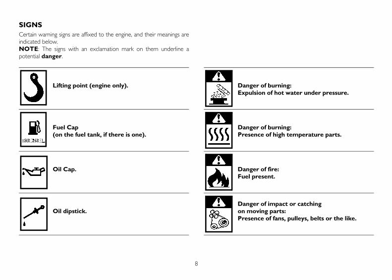
SIGNSCertain warning signs are affixed to the engine, and their meanings areindicated below.NOTE: The signs with an exclamation mark on them underline apotential danger.
Lifting point (engine only).
Fuel Cap (on the fuel tank, if there is one).
Oil Cap.
Oil dipstick.
Danger of burning: Expulsion of hot water under pressure.
Danger of burning: Presence of high temperature parts.
Danger of fire: Fuel present.
Danger of impact or catching on moving parts: Presence of fans, pulleys, belts or the like.
9
EN
GL
ISH
USE
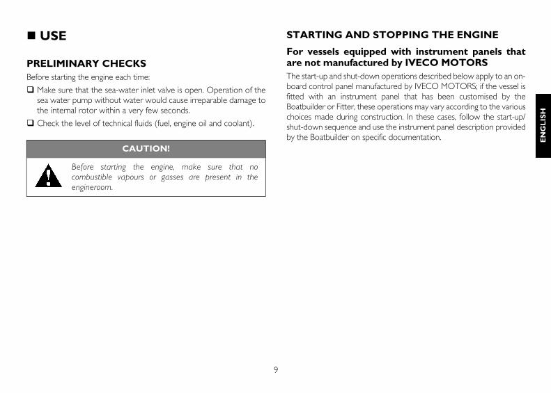
PRELIMINARY CHECKSBefore starting the engine each time:
Make sure that the sea-water inlet valve is open. Operation of thesea water pump without water would cause irreparable damage tothe internal rotor within a very few seconds.
Check the level of technical fluids (fuel, engine oil and coolant).
STARTING AND STOPPING THE ENGINE
For vessels equipped with instrument panels thatare not manufactured by IVECO MOTORSThe start-up and shut-down operations described below apply to an on-board control panel manufactured by IVECO MOTORS; if the vessel isfitted with an instrument panel that has been customised by theBoatbuilder or Fitter, these operations may vary according to the variouschoices made during construction. In these cases, follow the start-up/shut-down sequence and use the instrument panel description providedby the Boatbuilder on specific documentation.
CAUTION!
Before starting the engine, make sure that nocombustible vapours or gasses are present in theengineroom.
10
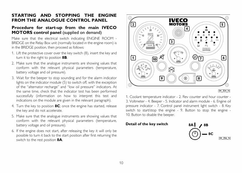
STARTING AND STOPPING THE ENGINEFROM THE ANALOGUE CONTROL PANEL
Procedure for start-up from the main IVECOMOTORS control panel (supplied on demand)Make sure that the electrical switch indicating ENGINE ROOM -BRIDGE on the Relay Box unit (normally located in the engine room) isin the BRIDGE position, then proceed as follows:
1. Lift the protective cover over the key switch (8), insert the key andturn it to the right to position 8B.
2. Make sure that the analogue instruments are showing values thatconform with the relevant physical parameters (temperature,battery voltage and oil pressure).
3. Wait for the beeper to stop sounding and for the alarm indicatorlights on the indicator module (5) to switch off, with the exceptionof the “alternator recharge” and “low oil pressure” indicators. Atthe same time, check that the indicator test has been performedsuccessfully (information on how to interpret this test andindications on the module are given in the relevant paragraph).
4. Turn the key to position 8C; once the engine has started, releasethe key and do not accelerate.
5. Make sure that the analogue instruments are showing values thatconform with the relevant physical parameters (temperature,battery voltage and oil pressure).
6. If the engine does not start, after releasing the key it will only bepossible to turn it back to the start position after first returning theswitch to the rest position 8A.
1. Coolant temperature indicator - 2. Rev counter and hour counter -3. Voltmeter - 4. Beeper - 5. Indicator and alarm module - 6. Engine oilpressure indicator - 7. Control panel instrument light switch - 8. Keyswitch to start/stop the engine - 9. Button to stop the engine -10. Button to disable the beeper.
1
2
3
45
67
89
10
04_354_N
8A 8B
8C04_356_N
Detail of the key switch
11
EN
GL
ISH
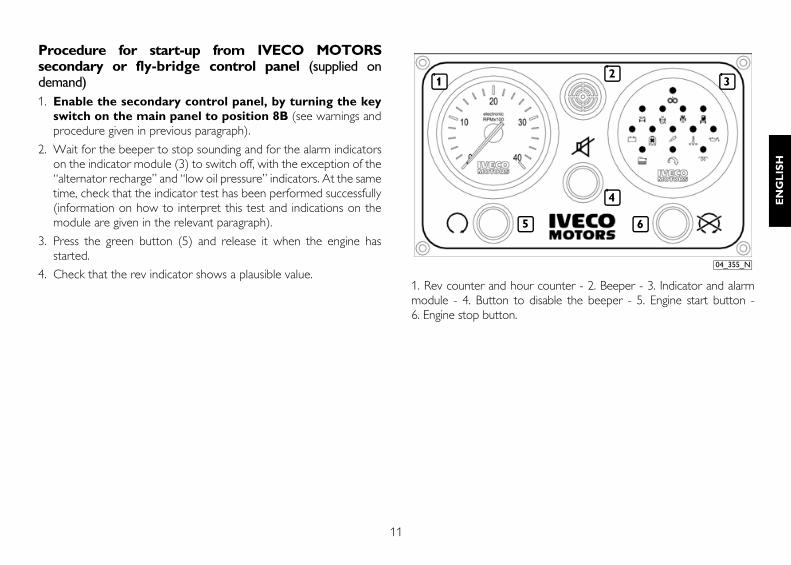
Procedure for start-up from IVECO MOTORSsecondary or fly-bridge control panel (supplied ondemand)1. Enable the secondary control panel, by turning the key
switch on the main panel to position 8B (see warnings andprocedure given in previous paragraph).
2. Wait for the beeper to stop sounding and for the alarm indicatorson the indicator module (3) to switch off, with the exception of the“alternator recharge” and “low oil pressure” indicators. At the sametime, check that the indicator test has been performed successfully(information on how to interpret this test and indications on themodule are given in the relevant paragraph).
3. Press the green button (5) and release it when the engine hasstarted.
4. Check that the rev indicator shows a plausible value.1. Rev counter and hour counter - 2. Beeper - 3. Indicator and alarmmodule - 4. Button to disable the beeper - 5. Engine start button -6. Engine stop button.
5
1 32
6
4
04_355_N
12
Stopping the engine
Before stopping the engine it is recommended you run it for a fewminutes at minimum speed with no load; this will allow the temperatureto drop evenly and will avoid harmful thermal shocks.
A. The engine is normally stopped from the main IVECO MOTORScontrol panel by turning the key switch to the rest position 8A orby turning a similar command on the customised control panel.
B. The IVECO MOTORS secondary control panel is stopped bypressing the red button (6) on the control panel.
The main IVECO MOTORS control panel for engines equipped with an“excited” device (on request or as prescribed by the CertificationBody), is stopped by pressing the red button (9).
To re-start the engine from the main control panel:
1. Return the key switch to the rest position 8A to reset all the on-board control panel functions.
2. Proceed as indicated.
To re-start the engine from the secondary control panel:
1. Make sure that the panel has been enabled (key switch on the maincontrol panel turned to position 8B).
2. Press the green button (5) and release it when the engine hasstarted, making sure that the rev indicator is showing a plausiblereading.
13
EN
GL
ISH
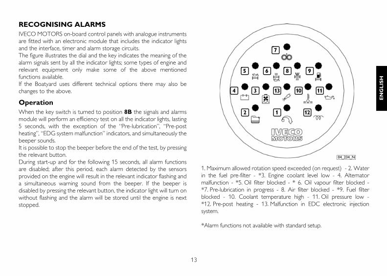
RECOGNISING ALARMSIVECO MOTORS on-board control panels with analogue instrumentsare fitted with an electronic module that includes the indicator lightsand the interface, timer and alarm storage circuits.The figure illustrates the dial and the key indicates the meaning of thealarm signals sent by all the indicator lights; some types of engine andrelevant equipment only make some of the above mentionedfunctions available.If the Boatyard uses different technical options there may also bechanges to the above.
OperationWhen the key switch is turned to position 8B the signals and alarmsmodule will perform an efficiency test on all the indicator lights, lasting5 seconds, with the exception of the “Pre-lubrication”, “Pre-postheating”, “EDG system malfunction” indicators, and simultaneously thebeeper sounds.It is possible to stop the beeper before the end of the test, by pressingthe relevant button.During start-up and for the following 15 seconds, all alarm functionsare disabled; after this period, each alarm detected by the sensorsprovided on the engine will result in the relevant indicator flashing anda simultaneous warning sound from the beeper. If the beeper isdisabled by pressing the relevant button, the indicator light will turn onwithout flashing and the alarm will be stored until the engine is nextstopped.
1. Maximum allowed rotation speed exceeded (on request) - 2. Waterin the fuel pre-filter - *3. Engine coolant level low - 4. Alternatormalfunction - *5. Oil filter blocked - * 6. Oil vapour filter blocked -*7. Pre-lubrication in progress - 8. Air filter blocked - *9. Fuel filterblocked - 10. Coolant temperature high - 11. Oil pressure low -*12. Pre-post heating - 13. Malfunction in EDC electronic injectionsystem.
*Alarm functions not available with standard setup.
12 12
11101334
5 6 8 9
7
04_234_N
14
STARTING AND STOPPING THE ENGINEFROM THE DIGITAL CONTROL PANEL
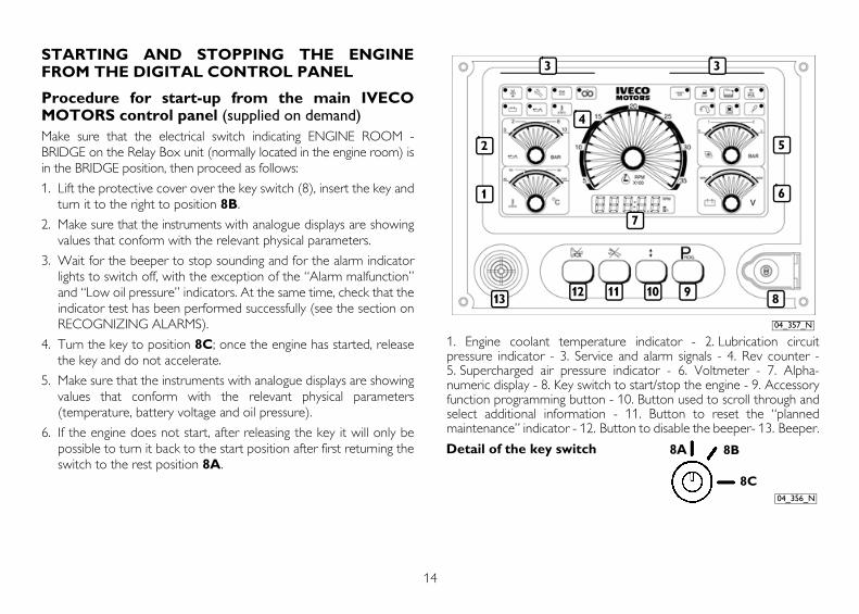
Procedure for start-up from the main IVECOMOTORS control panel (supplied on demand)Make sure that the electrical switch indicating ENGINE ROOM -BRIDGE on the Relay Box unit (normally located in the engine room) isin the BRIDGE position, then proceed as follows:
1. Lift the protective cover over the key switch (8), insert the key andturn it to the right to position 8B.
2. Make sure that the instruments with analogue displays are showingvalues that conform with the relevant physical parameters.
3. Wait for the beeper to stop sounding and for the alarm indicatorlights to switch off, with the exception of the “Alarm malfunction”and “Low oil pressure” indicators. At the same time, check that theindicator test has been performed successfully (see the section onRECOGNIZING ALARMS).
4. Turn the key to position 8C; once the engine has started, releasethe key and do not accelerate.
5. Make sure that the instruments with analogue displays are showingvalues that conform with the relevant physical parameters(temperature, battery voltage and oil pressure).
6. If the engine does not start, after releasing the key it will only bepossible to turn it back to the start position after first returning theswitch to the rest position 8A.
1. Engine coolant temperature indicator - 2. Lubrication circuitpressure indicator - 3. Service and alarm signals - 4. Rev counter -5. Supercharged air pressure indicator - 6. Voltmeter - 7. Alpha-numeric display - 8. Key switch to start/stop the engine - 9. Accessoryfunction programming button - 10. Button used to scroll through andselect additional information - 11. Button to reset the “plannedmaintenance” indicator - 12. Button to disable the beeper- 13. Beeper.
1
2
4
6
5
89111213
3 3
10
7
04_357_N
8A 8B
8C04_356_N
Detail of the key switch
15
EN
GL
ISH
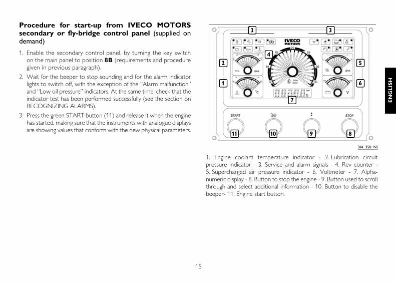
Procedure for start-up from IVECO MOTORSsecondary or fly-bridge control panel (supplied ondemand)
1. Enable the secondary control panel, by turning the key switchon the main panel to position 8B (requirements and proceduregiven in previous paragraph).
2. Wait for the beeper to stop sounding and for the alarm indicatorlights to switch off, with the exception of the “Alarm malfunction”and “Low oil pressure” indicators. At the same time, check that theindicator test has been performed successfully (see the section onRECOGNIZING ALARMS).
3. Press the green START button (11) and release it when the enginehas started, making sure that the instruments with analogue displaysare showing values that conform with the new physical parameters.
1. Engine coolant temperature indicator - 2. Lubrication circuitpressure indicator - 3. Service and alarm signals - 4. Rev counter -5. Supercharged air pressure indicator - 6. Voltmeter - 7. Alpha-numeric display - 8. Button to stop the engine - 9. Button used to scrollthrough and select additional information - 10. Button to disable thebeeper- 11. Engine start button.
1
2
6
5
3 3
4
7
1011 9 8
04_358_N
16
Stopping the engineBefore stopping the engine it is recommended you run it for a fewminutes at minimum speed with no load; this will allow thetemperature to drop evenly and will avoid harmful thermal shocks.
A. From the main IVECO MOTORS control panel: turn thekey switch to the rest position 8A.
B. From the secondary IVECO MOTORS control panel:press the red STOP button (8).
To re-start the engine from the main control panel:
1. Return the key switch to the rest position 8A to reset all the on-board control panel functions.
2. Proceed as indicated in the relevant paragraph.
To re-start the engine from the secondary control panel:
1. Make sure that the panel has been enabled (key switch on the maincontrol panel turned to position 8B).
2. START button (11) and release it when the engine has started,making sure that the instruments with analogue displays areshowing plausible values.
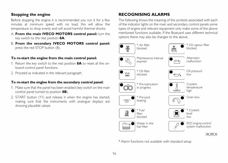
RECOGNISING ALARMSThe following shows the meaning of the symbols associated with eachof the indicator lights on the main and secondary control panels sometypes of engine and relevant equipment only make some of the abovementioned functions available. If the Boatyard uses different technicaloptions there may also be changes to the above.
* Alarm functions not available with standard setup
04_359_N
* Oil vapour filter blocked
Alternator malfunction
Oil pressure low
Coolant temperature high
Over-revs
* Coolant level low
EDC engine control system malfunction
* Air filter blocked
Maintenance interval expired
* Oil filter blocked
* Pre-lubrication in progress
* Pre-post heating
* Fuel filter blocked
Water in the fuel filter
17
EN
GL
ISH
OperationWhen the key switch is turned to position 8B an efficiency test will beperformed on all the indicator lights, lasting 5 seconds, with theexception of the “Pre-lubrication”, “Pre-post heating”, “EDCelectronic injection system malfunction” indicators, and simultaneouslythe beeper sounds; It is possible to stop the beeper before the end ofthe test, by pressing the relevant button.During start-up and for the following 15 seconds, all alarm functionsare disabled; after this period, each alarm detected by the sensorsprovided on the engine will result in the relevant indicator flashing anda simultaneous warning sound from the beeper. If the beeper isdisabled by pressing the relevant button, the indicator light will turn onwithout flashing and the alarm will be stored until the engine isstopped.
Alpha-numeric displayThis provides the following information:
• engine running speed
• total running hours (see note A)
• exhaust gas temperature (on request)
• instant fuel consumption (see note B)
The information required is selected by pressing the “Scroll select”button on both the control panels, main and secondary.
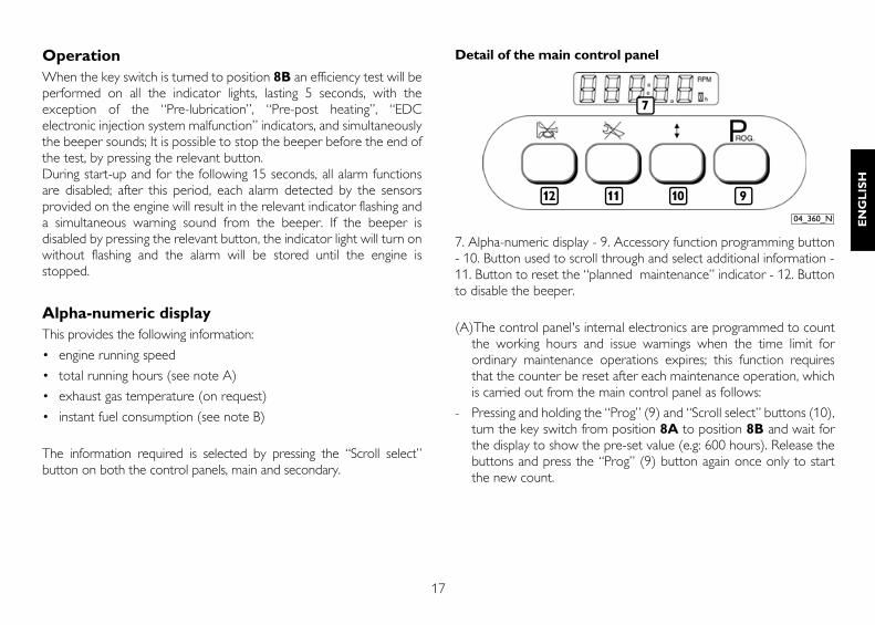
Detail of the main control panel
7. Alpha-numeric display - 9. Accessory function programming button- 10. Button used to scroll through and select additional information -11. Button to reset the “planned maintenance” indicator - 12. Buttonto disable the beeper.
(A)The control panel's internal electronics are programmed to countthe working hours and issue warnings when the time limit forordinary maintenance operations expires; this function requiresthat the counter be reset after each maintenance operation, whichis carried out from the main control panel as follows:
- Pressing and holding the “Prog” (9) and “Scroll select” buttons (10),turn the key switch from position 8A to position 8B and wait forthe display to show the pre-set value (e.g: 600 hours). Release thebuttons and press the “Prog” (9) button again once only to startthe new count.
912 11 10
04_360_N
7
18
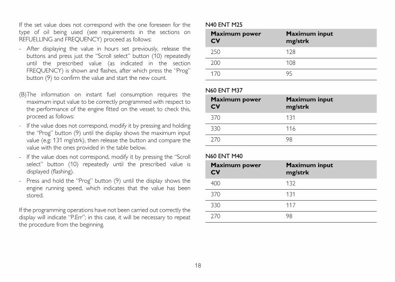
If the set value does not correspond with the one foreseen for thetype of oil being used (see requirements in the sections onREFUELLING and FREQUENCY) proceed as follows:
- After displaying the value in hours set previously, release thebuttons and press just the “Scroll select” button (10) repeatedlyuntil the prescribed value (as indicated in the sectionFREQUENCY) is shown and flashes, after which press the “Prog”button (9) to confirm the value and start the new count.
(B)The information on instant fuel consumption requires themaximum input value to be correctly programmed with respect tothe performance of the engine fitted on the vessel; to check this,proceed as follows:
- If the value does not correspond, modify it by pressing and holdingthe “Prog” button (9) until the display shows the maximum inputvalue (e.g: 131 mg/strk), then release the button and compare thevalue with the ones provided in the table below.
- If the value does not correspond, modify it by pressing the “Scrollselect” button (10) repeatedly until the prescribed value isdisplayed (flashing).
- Press and hold the “Prog” button (9) until the display shows theengine running speed, which indicates that the value has beenstored.
If the programming operations have not been carried out correctly thedisplay will indicate “P.Err”; in this case, it will be necessary to repeatthe procedure from the beginning.
N40 ENT M25
N60 ENT M37
N60 ENT M40
Maximum power Maximum inputCV mg/strk
250 128
200 108
170 95
Maximum power Maximum inputCV mg/strk
370 131
330 116
270 98
Maximum power Maximum inputCV mg/strk
400 132
370 131
330 117
270 98
19
EN
GL
ISH
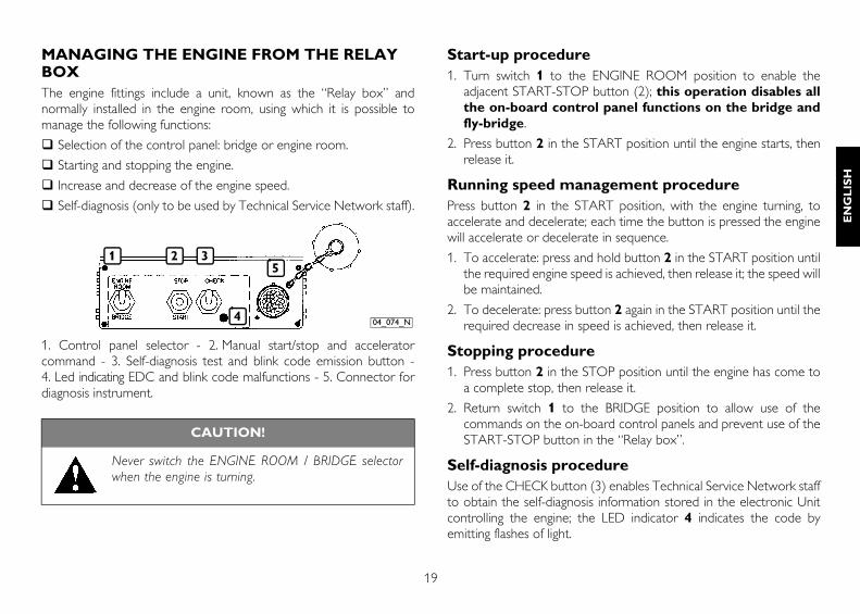
MANAGING THE ENGINE FROM THE RELAY BOXThe engine fittings include a unit, known as the “Relay box” andnormally installed in the engine room, using which it is possible tomanage the following functions:
Selection of the control panel: bridge or engine room.
Starting and stopping the engine.
Increase and decrease of the engine speed.
Self-diagnosis (only to be used by Technical Service Network staff).
1. Control panel selector - 2. Manual start/stop and acceleratorcommand - 3. Self-diagnosis test and blink code emission button -4. Led indicating EDC and blink code malfunctions - 5. Connector fordiagnosis instrument.
Start-up procedure1. Turn switch 1 to the ENGINE ROOM position to enable the
adjacent START-STOP button (2); this operation disables allthe on-board control panel functions on the bridge andfly-bridge.
2. Press button 2 in the START position until the engine starts, thenrelease it.
Running speed management procedurePress button 2 in the START position, with the engine turning, toaccelerate and decelerate; each time the button is pressed the enginewill accelerate or decelerate in sequence.
1. To accelerate: press and hold button 2 in the START position untilthe required engine speed is achieved, then release it; the speed willbe maintained.
2. To decelerate: press button 2 again in the START position until therequired decrease in speed is achieved, then release it.
Stopping procedure1. Press button 2 in the STOP position until the engine has come to
a complete stop, then release it.
2. Return switch 1 to the BRIDGE position to allow use of thecommands on the on-board control panels and prevent use of theSTART-STOP button in the “Relay box”.
Self-diagnosis procedureUse of the CHECK button (3) enables Technical Service Network staffto obtain the self-diagnosis information stored in the electronic Unitcontrolling the engine; the LED indicator 4 indicates the code byemitting flashes of light.
CAUTION!
Never switch the ENGINE ROOM / BRIDGE selectorwhen the engine is turning.
1 2 3
4
5
04_074_N
20
FOR PROPER USE OF THE ENGINEDo not continue to press the starter, when the engine has started.
Do not remain in dock while waiting for the engine to warm up,but after starting, commence navigation at low speed; the workingtemperature will be reached properly with the engine running atmedium speeds.
Do not operate the engine at minimum speed for long periods, asthis encourages the production of harmful exhaust and does notguarantee optimum performance.
The engine speed must be increased and decreased gradually, toallow regular combustion and proper operation of all enginecomponents.
The maximum cruising speed must not be more than 90% of thespeed corresponding to maximum power (see section on ENGINETECHNICAL DATA).
During navigation, check that:
• The engine coolant temperature does not reach the alarmthreshold.
• The oil pressure remains within normal values.
SPECIAL WARNINGS
Coolant temperature highIf the temperature indicated on the instrument is considered too high,or if the alarm is displayed, reduce speed and return to port to checkthe state of the sea water intake and cooling system circuits; also checkand have checked:
• tension of the water pump and alternator command belts.
• operation of the thermostat valve.
• whether or not the heat exchangers are clean.
Low lubricant pressureIf the pressure indicated by the instrument is considered insufficient, orif the “low oil pressure” indicator lights up, stop the engine and checkthe oil level. Top up if necessary (see CONTROL ANDMAINTENANCE section).If the condition persists, return to port at low speed and contact anAuthorised Service Centre.
CAUTION!
When the engine is warm, a pressure liable to causehot liquid to be expelled with extreme violence iscreated within the cooling circuits. This results in adanger of burning. Only open the coolant tank cap ifstrictly necessary, and only when the engine is cold.
21
EN
GL
ISH
Water in the fuel pre-filterIt is a good rule to drain the water from the filters, before the relevantindicator comes on.Avoid using the engine with the fuel tank only a small reserve of fuel;this encourages the formation of condensation and makes it morelikely you will suck up dirt or air, resulting in engine stoppage.
Air filter blocked and exhaust circuit inefficientInspect the cleanliness of the air intakes and discharge pipes on aregular basis. The maintenance intervals indicated in this manual onlytake into account the performance of engine components, and not anyadditional fittings installed by the Boatbuilder and any external events.
Alternator malfunctionCheck it or have it checked periodically for cleanliness, wear and propertensioning of the drive belt.
Irregularities in the electrical system Periodically check, particularly during the winter, to ensure that thebatteries are clean and in full working order, checking and topping upas indicated in the section CONTROLS AND MAINTENANCE,always taking due note of the WARNINGS provided. If it should benecessary to replace them, always comply with the characteristicsindicated in the section ENGINE TECHNICAL DATA.
RUNNING INThanks to modern engine construction technology, no particular runningin procedure is required. However, it is recommended that, for the first50 hours, you do not use the engine at high power for long periods.
CAUTION!
When refuelling, always pay great care to ensure thatno solid or liquid pollutants enter the fuel tank; youmust also remember that smoking and live flames areprohibited when refuelling.
CAUTION!
Visually check that the exhaust circuit is not blocked ordamaged, so as to prevent dangerous fumes within thevessel.
CAUTION!
The drive members are located under protective casings.These must only be removed when the engine is notturning.
22
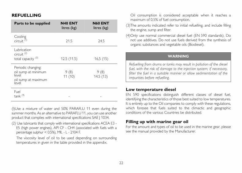
REFUELLING
(I)Use a mixture of water and 50% PARAFLU 11 even during thesummer months. As an alternative to PARAFLU 11, you can use anotherproduct that complies with international specifications SAE J 1034.
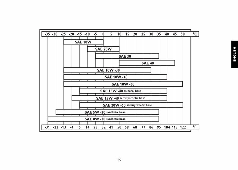
(2) Use lubricants that comply with international specifications ACEA E3 -E5 (high power engines), API CF - CH4 (associated with fuels with apercentage sulphur < 0.5%), MIL - L - 2104 F.
The viscosity level of oil to be used depending on surroundingtemperatures in given in the table provided in the appendix.
Oil consumption is considered acceptable when it reaches amaximum of 0.5% of fuel consumption.
(3)The amounts indicated refer to initial refuelling, and include fillingthe engine, sump and filter.
(4)Only use normal commercial diesel fuel (EN 590 standards). Donot use additives. Do not use fuels derived from the synthesis oforganic substances and vegetable oils (Biodiesel).
Low temperature dieselEN 590 specifications distinguish different classes of diesel fuel,identifying the characteristics of those best suited to low temperatures.It is entirely up to the Oil companies to comply with these regulations,which foresee that fuels suited to the climactic and geographicconditions of the various Countries be distributed.
Filling up with marine gear oilFor the amount and types of oil to be used in the marine gear, pleasesee the manual provided by the Manufacturer.
Parts to be supplied N40 ENT litres (kg)
N60 ENT litres (kg)
Coolingcircuit (1) 21.5 24.5
Lubricationcircuit (2)
total capacity (3) 12.5 (11.5) 16,5 (15)
Periodic changing:oil sump at minimum leveloil sump at maximum level
9 (8)11 (10)
9 (8)14.5 (13)
Fueltank (4) - -
WARNING
Refuelling from drums or tanks may result in pollution of the dieselfuel, with the risk of damage to the injection system; if necessary,filter the fuel in a suitable manner or allow sedimentation of theimpurities before refuelling.
23
EN
GL
ISH
CONTROLS AND MAINTENANCE
MAINTENANCE PERSONNELThe engine control and maintenance operations described in thefollowing chapter require training, experience and compliance withcurrent safety regulations; for this reason they must be carried out byspecial technicians, as indicated below.
Controls: by workshop technicians or the vessel user if necessary.
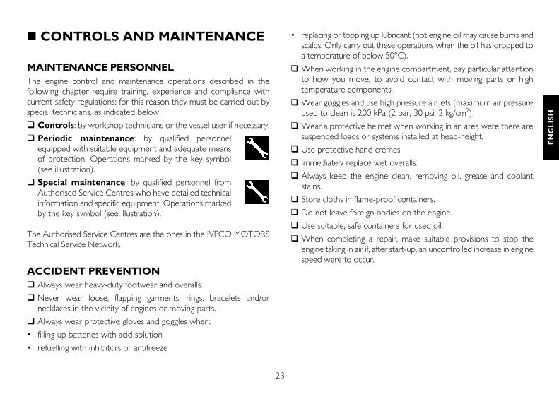
Periodic maintenance: by qualified personnelequipped with suitable equipment and adequate meansof protection. Operations marked by the key symbol(see illustration).
Special maintenance: by qualified personnel fromAuthorised Service Centres who have detailed technicalinformation and specific equipment. Operations markedby the key symbol (see illustration).
The Authorised Service Centres are the ones in the IVECO MOTORSTechnical Service Network.
ACCIDENT PREVENTIONAlways wear heavy-duty footwear and overalls.
Never wear loose, flapping garments, rings, bracelets and/ornecklaces in the vicinity of engines or moving parts.
Always wear protective gloves and goggles when:
• filling up batteries with acid solution
• refuelling with inhibitors or antifreeze
• replacing or topping up lubricant (hot engine oil may cause burns andscalds. Only carry out these operations when the oil has dropped toa temperature of below 50°C).
When working in the engine compartment, pay particular attentionto how you move, to avoid contact with moving parts or hightemperature components.
Wear goggles and use high pressure air jets (maximum air pressureused to clean is 200 kPa (2 bar, 30 psi, 2 kg/cm2).
Wear a protective helmet when working in an area were there aresuspended loads or systems installed at head-height.
Use protective hand cremes.
Immediately replace wet overalls.
Always keep the engine clean, removing oil, grease and coolantstains.
Store cloths in flame-proof containers.
Do not leave foreign bodies on the engine.
Use suitable, safe containers for used oil.
When completing a repair, make suitable provisions to stop theengine taking in air if, after start-up, an uncontrolled increase in enginespeed were to occur.
24
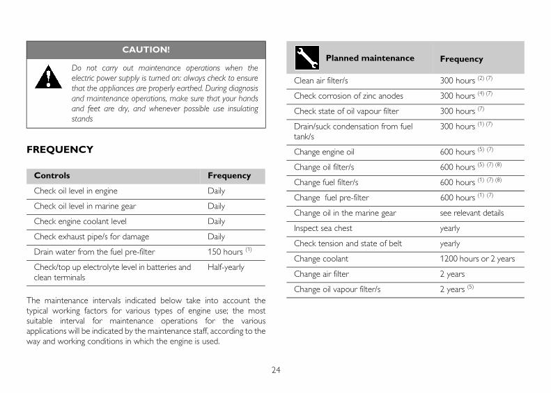
FREQUENCY
The maintenance intervals indicated below take into account thetypical working factors for various types of engine use; the mostsuitable interval for maintenance operations for the variousapplications will be indicated by the maintenance staff, according to theway and working conditions in which the engine is used.
CAUTION!
Do not carry out maintenance operations when theelectric power supply is turned on: always check to ensurethat the appliances are properly earthed. During diagnosisand maintenance operations, make sure that your handsand feet are dry, and whenever possible use insulatingstands
Controls Frequency
Check oil level in engine Daily
Check oil level in marine gear Daily
Check engine coolant level Daily
Check exhaust pipe/s for damage Daily
Drain water from the fuel pre-filter 150 hours (1)
Check/top up electrolyte level in batteries and clean terminals
Half-yearly
Planned maintenance Frequency
Clean air filter/s 300 hours (2) (7)
Check corrosion of zinc anodes 300 hours (4) (7)
Check state of oil vapour filter 300 hours (7)
Drain/suck condensation from fuel tank/s
300 hours (1) (7)
Change engine oil 600 hours (5) (7)
Change oil filter/s 600 hours (5) (7) (8)
Change fuel filter/s 600 hours (1) (7) (8)
Change fuel pre-filter 600 hours (1) (7)
Change oil in the marine gear see relevant details
Inspect sea chest yearly
Check tension and state of belt yearly
Change coolant 1200 hours or 2 years
Change air filter 2 years
Change oil vapour filter/s 2 years (5)
25
EN
GL
ISH
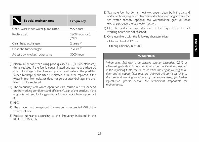
I) Maximum period when using good quality fuel , (EN 590 standard);this is reduced if the fuel is contaminated and alarms are triggereddue to blockage of the filters and presence of water in the pre-filter.When blockage of the filter is indicated, it must be replaced. If thewater in pre-filter indicator does not go out after drainage, the pre-filter must be replaced.
2) The frequency with which operations are carried out will dependon the working conditions and efficiency/wear of the product. If theengine is not used for long periods of time, check it before you startit.
3) N.C.
4) The anode must be replaced if corrosion has exceeded 50% of thevolume of zinc.
5) Replace lubricants according to the frequency indicated in theREFUELLING table.
6) Sea water/combustion air heat exchanger: clean both the air andwater sections; engine coolant/sea water heat exchanger: clean thesea water section; optional sea water/marine gear oil heatexchanger: clean the sea water section.
7) Must be performed annually, even if the required number ofworking hours are not reached.
8) Only use filters with the following characteristics:
- filtration level < 12 µm
- filtering efficiency ß > 200.
Special maintenance Frequency
Check wear in sea water pump rotor 900 hours
Replace belt 1200 hours or 2 years
Clean heat exchangers 2 years (6)
Clean the turbocharger 2 years (5)
Adjust play in valves-rocker arms 3000 hours WARNING
When using fuel with a percentage sulphur exceeding 0.5%, orwhen using oils that do not comply with the specifications providedin the refuelling table, the times at which the engine oil, engine oilfilter and oil vapour filter must be changed will vary according tothe use and working conditions of the engine itself; for furtherinformation, please consult the technicians responsible formaintenance.
26
REQUIREMENTS1. Do not disconnect the batteries with the engine running.
2. Do not carry out arc welding operations in the vicinity of the enginewithout first removing electrical cables and electronic units.
3. After each maintenance operation involving disconnection of thebattery/batteries, make sure that the terminals have been properlylocked onto the poles.
4. Do not use battery chargers to start the engine.
5. Disconnect the on-board network battery/batteries whenrecharging.
6. Do not paint the appliances, components and electrical connectorsequipping the engine.
7. Disconnect the battery/batteries before any electrical operations.
8. Contact the Boatyard before installing electronic equipment onboard (two-way radios, echo-sounding equipment, etc.).
HOW TO PROCEED
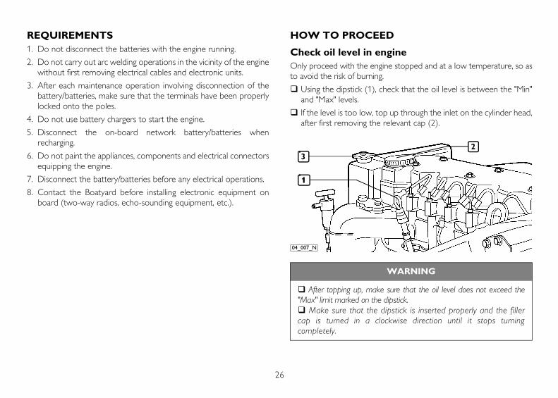
Check oil level in engineOnly proceed with the engine stopped and at a low temperature, so asto avoid the risk of burning.
Using the dipstick (1), check that the oil level is between the "Min"and "Max" levels.
If the level is too low, top up through the inlet on the cylinder head,after first removing the relevant cap (2).
WARNING
After topping up, make sure that the oil level does not exceed the"Max" limit marked on the dipstick.
Make sure that the dipstick is inserted properly and the fillercap is turned in a clockwise direction until it stops turningcompletely.
32
1
04_007_N
27
EN
GL
ISH
Check oil level in marine gearCheck the oil level in the marine gear following the indications providedin the marine gear Manufacturer's manual.
Check coolant levelOnly proceed with the engine stopped and at a low temperature, so asto avoid the risk of burning.
Remove the loading tank pressurisation cap (3 - previous page).
Visually check the coolant level.
Top up the tank if necessary, using a mixture of 50% clean water(not distilled) and Paraflù 11 (see REFUELLING table).
Check exhaust pipe/s for damageVisually check that the exhaust system is not blocked or damaged.
Make sure that there is no risk of dangerous fumes within thevessel. Contact the Boatyard if necessary.
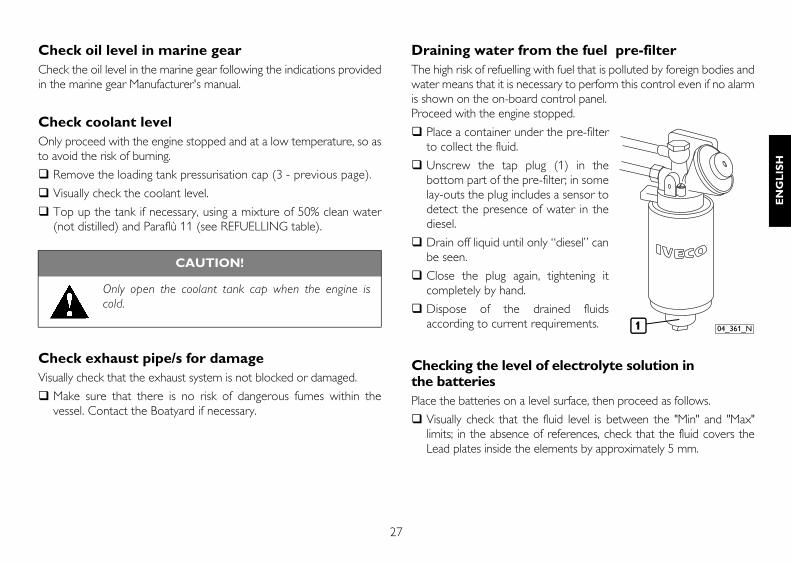
Draining water from the fuel pre-filterThe high risk of refuelling with fuel that is polluted by foreign bodies andwater means that it is necessary to perform this control even if no alarmis shown on the on-board control panel.Proceed with the engine stopped.
Place a container under the pre-filterto collect the fluid.
Unscrew the tap plug (1) in thebottom part of the pre-filter; in somelay-outs the plug includes a sensor todetect the presence of water in thediesel.
Drain off liquid until only “diesel” canbe seen.
Close the plug again, tightening itcompletely by hand.
Dispose of the drained fluidsaccording to current requirements.
Checking the level of electrolyte solution in the batteriesPlace the batteries on a level surface, then proceed as follows.
Visually check that the fluid level is between the "Min" and "Max"limits; in the absence of references, check that the fluid covers theLead plates inside the elements by approximately 5 mm.
CAUTION!
Only open the coolant tank cap when the engine iscold.
1 04_361_N
28
If necessary, top up with distilled water only those elements inwhich the level is below minimum.
Contact specialised technical staff if the battery needs recharging.
Have the efficiency of the battery recharging system tested if avoltage of less than 11 V (for 12 V rated systems) or 22 V (for24 V rated systems) is detected with the engine running.
On this occasion, make sure that the terminals and clamps areclean, properly locked and protected by vaseline.
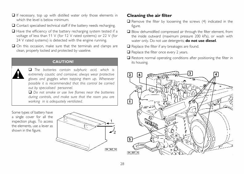
Some types of battery havea single cover for all theinspection plugs. To accessthe elements, use a lever asshown in the figure.
Cleaning the air filterRemove the filter by loosening the screws (4) indicated in thefigure.
Blow dehumidified compressed air through the filter element, fromthe inside outward (maximum pressure 200 kPa), or wash withwater only. Do not use detergents; do not use diesel.Replace the filter if any breakages are found.
Replace the filter once every 2 years.
Restore normal operating conditions after positioning the filter inits housing.CAUTION!
The batteries contain sulphuric acid, which isextremely caustic and corrosive; always wear protectivegloves and goggles when topping them up. Wheneverpossible it is recommended that this control be carriedout by specialised personnel.
Do not smoke or use live flames near the batteriesduring controls, and make sure that the room you areworking in is adequately ventilated.
04_362_N
1
2
5
4
04_007_N
6 3
29
EN
GL
ISH
Check corrosion of zinc anodesOnly proceed with the engine stopped and at a low temperature:
Provide suitable containers to ensure that no water is dispersedinside the vessel during removal of the anodes.
Remove the anodes, unscrewing them from their housings (seelocation in the section ENGINE TECHNICAL DATA).
Make sure that corrosion has not exceeded 50% of the volume ofzinc. If this is the case, change them.
Replace the anodes in their housings, locking them to theprescribed torque.
Check state of oil vapour filter (figure on page 28)Only proceed with the engine stopped and at a low temperature, soas to avoid the risk of burning:
Unfasten the screws and remove the cover (5) to the filtercompartment.
Remove the two filters and check them for deposits; if any depositsare found, replace them.
Replace the cover in its housing.
Changing engine oil (figure on page 28)Only proceed with the engine stopped and at a low temperature, so asto avoid the risk of burning.
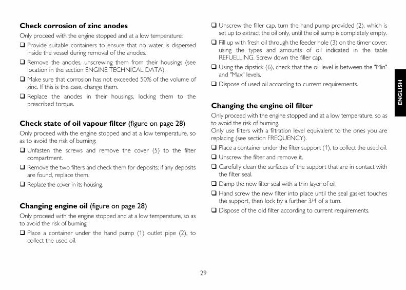
Place a container under the hand pump (1) outlet pipe (2), tocollect the used oil.
Unscrew the filler cap, turn the hand pump provided (2), which isset up to extract the oil only, until the oil sump is completely empty.
Fill up with fresh oil through the feeder hole (3) on the timer cover,using the types and amounts of oil indicated in the tableREFUELLING. Screw down the filler cap.
Using the dipstick (6), check that the oil level is between the "Min"and "Max" levels.
Dispose of used oil according to current requirements.
Changing the engine oil filterOnly proceed with the engine stopped and at a low temperature, so asto avoid the risk of burning.Only use filters with a filtration level equivalent to the ones you arereplacing (see section FREQUENCY).
Place a container under the filter support (1), to collect the used oil.
Unscrew the filter and remove it.
Carefully clean the surfaces of the support that are in contact withthe filter seal.
Damp the new filter seal with a thin layer of oil.
Hand screw the new filter into place until the seal gasket touchesthe support, then lock by a further 3/4 of a turn.
Dispose of the old filter according to current requirements.
30
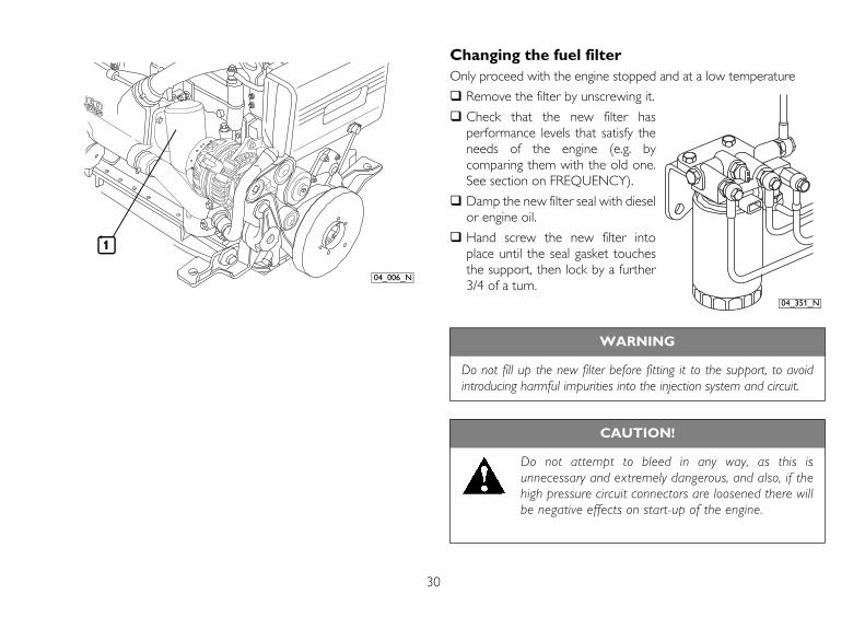
Changing the fuel filterOnly proceed with the engine stopped and at a low temperature
Remove the filter by unscrewing it.
Check that the new filter hasperformance levels that satisfy theneeds of the engine (e.g. bycomparing them with the old one.See section on FREQUENCY).
Damp the new filter seal with dieselor engine oil.
Hand screw the new filter intoplace until the seal gasket touchesthe support, then lock by a further3/4 of a turn.
1
04_006_N
WARNING
Do not fill up the new filter before fitting it to the support, to avoidintroducing harmful impurities into the injection system and circuit.
CAUTION!
Do not attempt to bleed in any way, as this isunnecessary and extremely dangerous, and also, if thehigh pressure circuit connectors are loosened there willbe negative effects on start-up of the engine.
04_351_N
31
EN
GL
ISH
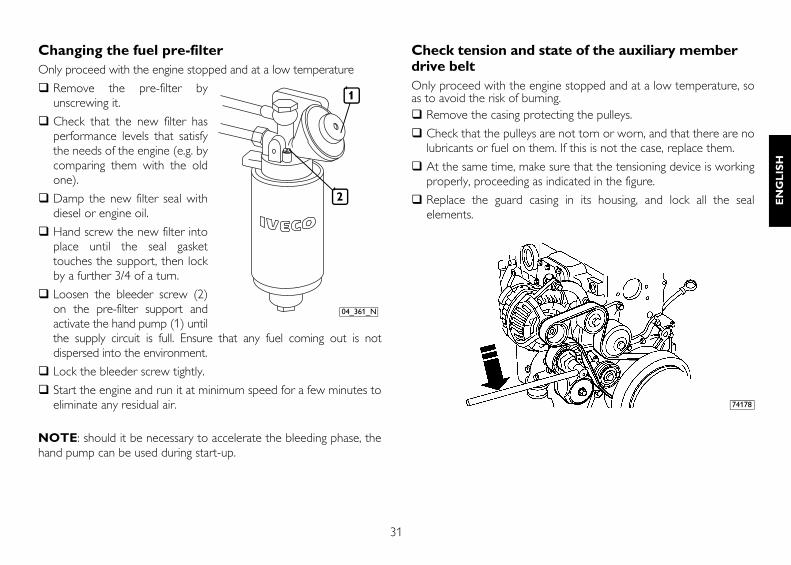
Changing the fuel pre-filterOnly proceed with the engine stopped and at a low temperature
Remove the pre-filter byunscrewing it.
Check that the new filter hasperformance levels that satisfythe needs of the engine (e.g. bycomparing them with the oldone).
Damp the new filter seal withdiesel or engine oil.
Hand screw the new filter intoplace until the seal gaskettouches the support, then lockby a further 3/4 of a turn.
Loosen the bleeder screw (2)on the pre-filter support andactivate the hand pump (1) untilthe supply circuit is full. Ensure that any fuel coming out is notdispersed into the environment.
Lock the bleeder screw tightly.
Start the engine and run it at minimum speed for a few minutes toeliminate any residual air.
NOTE: should it be necessary to accelerate the bleeding phase, thehand pump can be used during start-up.
Check tension and state of the auxiliary member drive beltOnly proceed with the engine stopped and at a low temperature, soas to avoid the risk of burning.
Remove the casing protecting the pulleys.
Check that the pulleys are not torn or worn, and that there are nolubricants or fuel on them. If this is not the case, replace them.
At the same time, make sure that the tensioning device is workingproperly, proceeding as indicated in the figure.
Replace the guard casing in its housing, and lock all the sealelements.
2
1
04_361_N
74178
32
Replace coolantOnly proceed with the engine stopped and at a low temperature, soas to avoid the risk of burning.
Provide suitable containers to ensure that no coolant is dispersedinto the environment.
Remove the plugs on the circuit components and wait until thecircuit has drained completely (the location of plugs is given in thesection ENGINE TECHNICAL DATA). After emptying, replace theplugs in their housings, making sure that the seal rings are allundamaged.
Fill up the circuit as indicated in the table REFUELLING.
Bleed the circuit and top-up if necessary.
Change oil vapour filter (figure on page 28)Only proceed with the engine stopped and at a low temperature, so asto avoid the risk of burning.
Unfasten the screws and remove the cover (5) to the filtercompartment.
Remove the two filters, and dispose of them according to currentrequirements.
Insert the new filters and replace the cover.
Drain/suck condensation from fuel tank/sInspect sea chestCheck sea water pump rotorClean heat exchangersClean the turbochargerAdjust play in valves-rocker arms
The method used to change the oil in the marine gear is indicated in therelevant documentation supplied by the Manufacturer of the marinegear itself.
WARNING
The operations listed below must only be carried out by qualified stafffrom the IVECO MOTORS Service Centres or by staff from theBoatbuilders.The methods used to perform them are described in the Technicaland Repair Manuals.
33
EN
GL
ISH
MOVING THE ENGINEThe operations necessary to embark and disembark the engine mustonly be carried out by technicians from Authorised Service Centres.When lifting the engine only, use the U-bolts indicated in this manualin the section ENGINE TECHNICAL DATA and marked on the enginewith special stickers.Lifting must be carried out using a rocker arm that keeps the metalcables supporting the engine parallel, using all the U-bolts providedsimultaneously; the use of a single U-bolt only is not allowed.The engine lifting system must have a capacity and size suited to theweight and dimensions of the engine; check that there is no interferencebetween the lifting system and the engine components.Do not lift the engine before removing the transmission members thatare coupled to it.
DISPOSAL OF WASTEThe engine is made up of parts and elements that, if discarded, maycause damage to the environment.The materials listed below must be handed over to specialisedCollection Centres; the laws in force in the various Countries foreseesevere penalties for transgressors:
Starter batteries.
Used lubricants.
Mixtures of water and antifreeze.
Filters.
Additional cleaning materials (e.g. greasy or fuel-soaked cloths).
34
LONG PERIODS OF INACTIVITY
PREPARING THE ENGINE FOR A LONGPERIOD OF INACTIVITYIn order to prevent oxidation of the internal parts of the engine and ofcertain components in the injection system, when the engine isexpected to be inoperative for periods of more than two months, thefollowing operations must be carried out in preparation for this:
1. Drain the lubricant from the sump, after first warming up theengine.
2. Fill the engine with protective oil type 30/M (or alternatively oil thatcomplies with MIL 2160B type 2 specifications), up to the"minimum" level indicated on the dipstick. Start the engine and keepit running for approximately 5 minutes.
3. Drain the fuel from the injection circuit, from the filter and from theinjection pump pipes.
4. Connect the fuel circuit to a tank containing CFB (ISO 4113)protective fluid, and feed in the fluid by putting the circuit underpressure and running the engine for approximately 2 minutes, afterfirst disabling the injection system. This operation can be performedby polarising terminal 50 of the starter motor with a positivevoltage equivalent to the rated voltage of the system, using aconductor provided for that purpose.
5. Nebulise approximately 60 g of 30/M protective oil (10 g per litredisplacement) into the turbocompressor suction inlet, during thepressurised filling operation described in the previous point.
6. Close all the suction, delivery, ventilation and bleeder openings inthe engine with suitable plugs, or seal them with adhesive tape.
7. Drain the residual 30/M protective oil from the sump. This oil canbe used again for a further 2 preparation operations.
8. Fit signs reading ENGINE WITHOUT OIL to the engine and to theon-board control panel.
9. Drain the coolant, if it has not been mixed with suitable antifreezeand corrosion inhibitors, and affix a sign to indicate the fact.
In the event of prolonged inactivity, the operations described must berepeated every 6 months, following the procedure given below:
A) drain the 30/M protective oil from the sump;
B) repeat the operations described from point 2 to point 7.
Should you intend to protect external parts of the engine, proceed byspraying OVER 19 AR protective liquid on unpainted metal parts, suchas the flywheel, pulleys and the like, avoiding belts, connector cables andelectrical equipment.
35
EN
GL
ISH
RESTARTING THE ENGINE AFTER A LONGPERIOD OF INACTIVITY1. Drain the residual 30/M protective oil from the sump.
2. Fill the engine, as prescribed, with lubricant of the type and amountindicated in the table REFUELLING.
3. Drain the CFB protective fluid from the fuel circuit, carrying out thisoperation as indicated under point 3. of PREPARING THEENGINE FOR A LONG PERIOD OF INACTIVITY.
4. Remove the plugs and/or seals from the suction, delivery,ventilation and bleeder openings in the engine, restoring it to anormal state of use. Connect the turbocharger suction inlet to theair filter.
5. Connect the fuel circuits to the vessel’s fuel tank, completing theoperations as indicated in point 4. of PREPARING THE ENGINEFOR A LONG PERIOD OF INACTIVITY. During filling operations,connect the fuel return pipe to a collection tank, so as to preventany residual CFB protective fluid from flowing into the vessel’s fueltank.
6. Check the engine and fill it up with coolant as prescribed.
7. Start the engine and keep it running until the idling speed rate hasstabilised completely.
8. Check that the instruments on the on-board control panel/s areshowing plausible values, and that no alarms are shown.
9. Stop the engine.
10.Remove the ENGINE WITHOUT OIL signs from the engine andfrom the on-board control panel.
36
ENGINE MALFUNCTIONS
The electronic unit overseeing management and control of all operationof the engine is capable of recognising any malfunctions that may occur,and of adopting strategies that will allow you to navigate in full safety.The event, signalled by light-up of the EDC MALFUNCTION indicatoron the on-board control panels, results in programmed limitation ofpower within certain thresholds, set according to the severity of thecase.In the case of temporary malfunctions the reduction in performance willremain in force until the engine is stopped.
Accelerator electronic circuit malfunctionWhen certain problems in the accelerator electric circuit are recognised,the Electronic Unit controlling the engine adopts a strategy known as“accelerated minimum speed running”, that will enable navigation tocontinue in emergency mode.The possible operating modes are as follows:
A. The accelerator lever does not “respond”: the running speedstabilises at 750 rpm. to allow the vessel to proceed slowly and bemanouevered simply by turning the marine gear on and off, with-out accelerating.
B. The accelerator lever “responds partially”: the minimum runningspeed is set to 750 rpm. When the accelerator lever is moved toapproximately half way, the speed gradually increases up to 2000rpm.; when the lever is returned to minimum the speed rapidlydecreases to 750 rpm.
NOTE: In mode “A” it is possible to proceed at speeds higher thanthe accelerated minimum, managing start/stop, acceleration anddeceleration functions as illustrated in the section MANAGING THEENGINE FROM THE RELAY BOX. Should it be necessary to operatethe engine as above, always comply with the accidentprevention rules provided in the Section “Controls andmaintenance.
CAUTION!
The engine electronic control unit can adopt safetystrategies at any time during navigation, shouldconditions arise that are considered to put the engineat risk. When conditions of this kind occur, proceed with thegreatest possible care and attention, first making surethat all those on board are secure and holding on tosafe hand-holds.
CAUTION!
Management of the engine from the “Relay box” involvesinhibition of the bridge controls; as a result of this, whenrunning the vessel from the bridge, the onlyway to stop propeller thrust in the enginequickly is using the marine gear disengagement lever.
37
EN
GL
ISH
EMERGENCIES ON BOARD
The user of a vessel that has been constructed according to safetyregulations, when following the instructions provided in this manual andthe indications given on the engine labels, will be working in safeconditions.Should improper conduct result in accidents, always request theintervention of trained first aid specialists immediately.In an emergency and while awaiting the arrival of first aid specialists,follow the instructions given below.
Engine malfunctionsWhen navigating with a malfunctioning engine, take the greatest possiblecare when manouevering and make sure that all those aboard areholding firmly to safe hand-holds (see section on ENGINEMALFUNCTIONS).
In case of fireExtinguish the fire using the fire-fighting equipment provided aboard, andin the manner indicated by Fire prevention authorities (the fire-fightingequipment required on board is compulsory under current safetylegislation).
Burns and scalds1. Extinguish any flames on the burned person's clothing, by:
• throwing water over them;
• using a powder fire-extinguisher, without directing the jet at theperson's face;
• covering with blankets or rolling the victim on the ground.
2. Do not attempt to remove pieces of clothing that may have stuckto the skin;
3. In the case of scalding, immediately but carefully remove anyclothing that may be soaked in the hot liquid;
4. Cover the burn with a special burn dressing or sterile bandage.
Carbon monoxide intoxication (CO)Carbon monoxide from the engine exhaust is without smell, and isdangerous both because it causes intoxication, and because whencombined with air it forms an explosive mixture.In closed rooms, carbon monoxide is extremely dangerous, as it canreach critical concentrations within a very short time.When assisting an intoxicated person in a closed room:
1. Ventilate the room immediately, to reduce the concentration ofgas.
2. When entering the room, hold your breath, do not light flames,lights or ring electric doorbells or phones, to avoid the risk ofexplosion.
3. Carry the intoxicated person out into the fresh air or into a wellventilated room, resting him on one side if he is unconscious.
38
ElectrocutionThe engine's electrical 12 V or 24 V electrical system does not involvethe risk of electrocution, however, in the event of a short-circuit caused,for example, by a metal tool, there is a risk of burning due to overheatingof the object through which the electrical current runs. In thesecircumstances:
1. Remove the object that caused the short-circuit, using means thatprovide sufficient heat insulation.
2. Switch off the power at the main switch, if there is one.
Injuries and fracturesThe vast number of possible circumstances and the specific nature ofoperations required means that the intervention of a medical team isnecessary.
1. In the event of bleeding, keep the edges of the wound pressedtogether until help arrives.
2. If there is any suspicion of a fracture, do not move the injured partand only move the patient if absolutely necessary.
Caustic burnsCaustic skin burns are caused by contact with extremely acid or alkalinesubstances.For electric maintenance technicians these are typically caused by acidfrom batteries; in these circumstances, proceed as follows:
1. Remove any clothing soaked in the caustic substance.
2. Wash the area with lots of running water, avoiding parts that havenot been burned.
If either battery acid, lubricants or diesel come into contact with theeyes: wash the eyes with water for at least 20 minutes, keeping theeyelids open so that the water flows over the eyeball (move the eye inall directions to wash more thoroughly).
39
EN
GL
ISH