Embed Size (px)
Citation preview

~R-AiB" 254 ANALYSIS OF THRECE-DIRENSIONARL VISCOUS INTERN LU lo2UB(U) CINCINNATI UNIV OH DEPT OF AEROSPACE ENGINEERINGAND ENGINEER K N GHIA ET AL 31 MAR 87
UNCLASSIFIED UC-ASE-87-6-71 AFOS-TR-87-t2i5 F/G 20/4
EhEEEEEEEEoiEEEmhEEEEmhhEEIEhhEEEEEEEEEEEIIE.II.... I
llllllll

L2
1.0 J L2
01.251 =4 Q6
WCR4XOPV FitSOLUION TtST mARI
60

jSIFIED .-
J)OCUMNTATION PAGEI&~~b olpl WRSTRICTIVE laAPIXINGS
AD-A 186 254 * 3
P, 3 g, CA I O4.OCONGNA Distribution Unlimited.
-f *l 'A a 4 OAGANiZAT1 IO T 04,14 IL MONITORING ORGAN4IZATION REPORT NUMBAR(SI
~,gaaGOPPEPORMINGORGAtNsZATIO90 OFFICE SYMBOL 7&. tA#M OF MONI1TOONING ORGANIZATION
.niversity oft Cincinnati Air Force Office of Scientific Research/NA
AD. 0ilk aSS , C. y.SSoft 411 7)? C~)e Ab. ADDRESS (csty, Stat a" ZIP Code,*Diepc:. of Aerospace Engg. &Engg. Mechanics Building 410
"*Dept. of Mechanical & Industrial Engineering Boiling Air Force Base, DC 20332U niv. of Cincinnati, Cincinnati, OH 45221 ________________________-ad. %A06o PuNtOiaNV BDORNG Opp. OIca SYMBOL B, PROCUREMENT INSTRUMENT IDENTIFICATION NUJMBER
oaaAftizATtON Air 'Force aIt aebd85e23Of fice of Scientific Research ANAR8-03
ft LOONE14s CdYv. Stae dad ZIP C~ge III SOURCE OF FUNDIONG Nos1.
Building 410 PROGRAM PROJECT TAK WRNT
Eolling Air Force Base. DC 20332 iUNNQ----%.NoN.
11 rITLA IEUe*Cfll laif sis of Three- ~6l20Dimensional Viscous Internal l1ows (Unclassifiek) y~\
12. "PsoNtAI AU?9411
Kirti N. Ghia* and TUrmila Ghia**13& TYPE OF REPORT 131L TIME COVERED Sept. 14. DATE OF REPORT (Yr.. Mo.. Dow, 15. PAGE COUNTI
Final Report PROM Ti RToJ9-L.- 1987, March, 31 .45
Is. SLIPPIMENTAVY 140TATION
COSATICOS coo, a. SIpICi TERMS lCoafauw a rw~yM Iat ueeemIrz)Omdlden dty bf ta nuam brD
0.t. GOCUP sue. on Viscous Flows I Interacting g=S Equations)'I Flow Separation) Multi,,. lock Structured Grids)
Unsteady Flows, Three-Obimensiona1 Flows19. ABSTRACT C041101140 On Pvvane ItOC106 e AF, mid@dnty &V IN1008 A011wbE?
A f if teen-month multi-tasked research project was pursued by the present
investigators to study complex Vsosflows under AORsponsorship between July 1985undestadin ofvisous low an todevlopbasic computational methods for
efficient determination of 2-D/3-D subsonic and incompressible flows. Two majoranalyses were pursued. These include the Interacting Parabolized Navier-Stokes (IPNS)an~alysis for steady flows and the full Navier-Stokes (NS) analysis fr directsimulation of unsteady flows. The IPNS analysis developed employs no ad hoc
* artificial dissipation and, In spite of being a density-based formulation, performswell. even for very low Mach numbers. The applications considered include 2-D cascadesand ch~annels of simple geometry. The flow solutions are well behaved in the presenceof sharp leading edges and trailin edges, as well as in the presence of reversed
*25. Os1'isL.TICAVAILASIITY OP A6STRA-:? 21. ABSTRACT SECURITY CLASSIFICATION
%CLASSIPIIDIUNLIMITlO 2 SAME AS PIPT Z OTIC useS UnclassieA.. - />I L ~22,. 4hM ~P NESPNSILE NO~lO~jAL22b TELEPmCNE NUMBER 2.O~c YUI
(IflcIIue A Fed Code,
*Dr. James D. Wilson 202-767-4935 NA
00 FORM 1473, 83 APR EDaITION Of I JAN 72 IS OBSOLETE. UNCL-ASSMFEn4 SECURITY CLASSIFICATION OF THIS PAGE
~~~~~~~~ % 'v . .. VV F

- I SIFIED -
,?V CLAS3IIgCATION OF TIs PAGE
19. ABSTRACT (Continued)
flow. The complete unsteady NS analysis is based on direct-solution methodology and
has proved to be very robust and efficient. It has been applied to analyze high-incidence aerodynamics of symmetric as well as cambered Joukowski airfoils, and has
yielded very interesting results regarding multiple incommensurate frequencies in the
- large-time behavior of the flow and, hence, regarding the theory of strange attractorsand chaos. The corresponding 3-D analysis appears well on its way and looks very
promising. All of this research relies heavily on usage of the supercomputers at the
NASA Research Centers, in addition to all the various computing and graphicsfacilities at the University of Cincinnati. Both the 2-D analyses developed are
reasonably mature now and should be useful for examining realistic flow phenomena.
18. SUBJECT TERMS (Continued)
Semi-Implicit and Implicit Numerical MethodsBlock-Gaussian Elimination MethodNeumann Pressure ProblemSupercomputer Application
i7
UNCLASSIFIEDSECURITY CLASSIFICATION OF THIS PACE
.............

REPORT NO. AFL 87-6-70
AFOSR -Tit. 8 7 1 21.5
ANALYSIS OF THREE-DIMENSIONAL VISOCUS INTERNAL FLOWS
K.N. GHIASA ND Accesior. For
U. GHIA TSCA
Disribtio of th. reprtisunlmied
June 1987
87 9 24 2

ANALYSIS OF THREE-DIMENSIONAL VISCOUS INTERNAL FLOWS
K.N. GHIA*Department of Aerospace Engineering and Engineering Mechanics
and
U. GHIA*Department of Mechanical and Industrial Engineering
University of CincinnatiCincinnati, Ohio
This research was supported by the Air Foroe Officeof Scientific Research, Bolling Air Force Base,under AFOSR Grant No. 85-0231, with Dr. James D. Wilsonas Technical Monitor.
Distribution of this report is unlimited.
* Professor.

ABSTRACT
A fifteen-month multi-tasked research project was pursued by the
present investigators to study complex viscous flows under AFOSR sponsorship
between July 1985 and September 1986. The major objective of this study was
to acquire improved understanding of viscous flows and to develop basic
computational methods for efficient determination of 2-D/3-D subsonic and
incompressible flows. Two major analyses were pursued. These include the
Interacting Parabolized Xavier-Stokes (ZPNS) analysis for steady flows and
the full Xavier-Stokes (NS) analysis for direct simulation of unsteady
flows. The IPUS analysis developed employs no ad hoc artificial dissipation
and, in spite of being a density-based formulation, performs well even for
very low Mach numbers. The applications considered include 2-D cascades and
channels of simple geometry. The flow solutions are well behaved in the
presence of sharp leading edges and trailing edges, as well as in the
presence of reversed flow. The complete unsteady IS analysis is based on
direct-solution methodology and has proved to be very robust and efficient.
It has been applied to analyze high-incidence aerodynamics of symmetric as
well as cambered JouIowski airfoils, and has yielded very interesting
results regarding multiple incommensurate frequencies in the large-time
behavior of the flow and, hence, regarding the theory of strange attractors
and ,haos. The corresponding 3-D analysis appears well on its way and looks
very promising. All of this research relies heavily on usage of the
supercomputers at the NASA Research Centers, in addition to all the various
computing and graphics facilities at the University of Cincinnati. Both the
2-D analyses developed are reasonably mature now and should be useful for
examining realistic flow phenomena.
raU A A A K Z _

TABLE OF CONTENTS
Section Papg
ABSTRACT............................................
1OBJECTIVES .............................. *..... 1
2 DESCRIPTION 01 ;_NIFICANT ACCOMPLISHMENTS ............. 3
2.1 Composite ceneration of Multi-Block Grids forSubsonic Cascades .. . ... .. . .. ................. . ... . ... 3
2.2 Steady Flows with Strong Upstream Interactions ... 5
2.3 Unsteady 2-D Navier-Stokes Analysis ...... ......... 9
2.14 Unsteady Three-Dimensional Navier-Stokes Analysis .. 17
2.5 Pressure-Field Evaluation for Unsteady Flows ....... 20
2.6 Supercomnputer Usage and Graphical Post-~~, ~Processing of Data ................... 20
REEECS.................2
3 JOURNAL PAPERS PUBLISHED AND IN PREPARATION ............ 241
41 SCIENTIFIC INTERACTIONS - SEMINAR AND PAPERPRESENTATIONS .*....................... *so ..... 26
5 STUDENT DEGREE THESES AND DISSERTATIONS ................ 28
FI U E . . . . . . . . . . . .. .o. . . .o. . . . . o2

LIST OF FIGURES
Figure Page
I H-Grid for Turbine Cascade With Rounded Leading Edges .... 29
2 Hybrid C-H Grid for Cascade - Patched Solution ........... 29
3 Computational Domain (3-D) for Hybrid Grid for HighlyStaggered Cascade . . .. .. . .. . . . . .................................. 30
14 Sub-Region Boundaries for Hybrid Grid .................... 31
5 2-D Comnputational Regions for Application of ADI Scheme
6 Results for Symmetric Channel with ExponentialConstriction; Re -1500, tmax /h-- 0.2, (201x61) Grid ... 32
7 Results for Flat-Plate Cascade Various Reynolds Numbers,C 186x71 ) Grid . . ... . . .. . .. ... . .. ... . ... .. .. . .. . . . ... . 33
8a Results for Symmetric Cascade of Parabolic Airfoils forVarious tma /c; Re - 1500, C186x71) Grid ......... 33
8b Results for Symmetric Cascade of Parabolic Airfoils forVarious Reynolds Nubers; tma/c -0.05, (186x71) Grid .314
8e Pressure Contours for Symmetric Cascade of ParabolicAirfoils; tma/c -0.05, M,.'0.149, Re-15,000 ...... 0..% ... 314
V.9 Instantaneous Aerodynamic Coefficients at Re-i ,000,a f 15. (a) Lift C Le (b) Drag C D' (c) Moment CM- Symmetric Joucowaici Airfoil .......................... 35
10 Instantaneous Aerodynamic Coefficients at Re-i .000,If 0
300. (a) Lift C L. Cb) Drag CD' (c) Moment CM
- Symmetric JoukoWski Airfoil .......................... 35
11 Instantaneous Aerodynamic Coefficients at Re-i .000,afUS 3 . (a) Lift C L. Cb) Drag CD. (c) Moment CM--Symmetric Joukowaki Airfoil .......................... 36
12 Typical Grid Distribution for Gottingen 580 Airfoil ...... 37
13 Gottingen 580 at Re-i ,000, a e05.7110; at t - 0: 37
Inviscid Stream Function and Grid Distribution att-18.0. Steady-State Solution .......................... 37
1.4 Lift and Drag Histories; Gottingen 580, ae=150 ........... 37
15 Lift and Drag Histories; Gottingen 580, (ze=30 * ...... 3
Maw_ ILI011

16 TE-LE-TE Vortex-Shedding Cycle for G~ttingen 580 Airfoilat Re - 1000, %-*300** ......... .. *........... .... .. . .. . 38
17 Developmuent of Flow Past Cylinder at Re - 200;Symmetry Not Assianed . . .. . . . . . ..... .. .. . . . .. .. . .. 39
18 Development of Symmetric Flow Past Cylinder atRe - 500 ....................................... ....... 40o
S iv

SECTION 1
OBJECTIVES
The development of computational fluid dynamics (CFD) analyses for
complex viscous interacting flows was pursued by the present investigators
during July 1985 - Sertember 1986. The major thrust of the work was in the
development of two analyses, which are briefly outlined as under:
Viscous Interacting Analysis: Internal Flows
Subsonic flows are essentially elliptic in character. However, in a
large class of internal flow applications, streamwise diffusion is
negligible, although upstream influences through pressure interactions are
significant. These situations can be analyzed and computed more efficiently
using the Interacting Parabolized Navier-Stokes (IPNS) model rather than the
full Navier-Stokes equations, particularly for steady flow. The IPNS model
and the corresponding numerical method were studied, with the objective of
developing an efficient procedure of desirable versatility for use in
studying flows in diffusers, cascades, etc.
Unsteady Navier-Stokes Analysis: Internal and External Flows
Unsteady separation and vorticity interactions in self-excited and
forced unsteady flows are important fundamental phenomena which occur in
internal as well as external flows. Unsteady separation in large-vortex
dominated flows is particularly important in external flows. The underlying
physical mechanisms were examined by analyzing flows exhibiting these
phenomena, with the help of the complete unsteady Navier-Stokes equations
solved using a direct (fully implicit) numerical technique.
i0 1

Additional items such as grid generation and development of solution
algorithms were also studied to further aid the above two analyses. These
items contribute significantly to basic research even by themselves.
Moreover, these essential elements were needed for successfully developing
the two main analyses.
A2
! __

SECTION 2
DESCRIPTION OF' SIGNIFICANT ACCOMPLISHMENTS
All of the areas of research proposed for study were pursued during
this 15-month grant period. The progress achieved in each of these areas is
briefly described in this section.
2.1 Composite Generation of Multi-Block Grids for Subsonic Cascades
Examination of the basic grids for cascades shows that a C-grid can
adequately resolve the boundary layers on the blades as well as the wakes
downstream and is satisfactory everywhere except in the region upstream of
the blades. In this region, the grid density decreases rapidly with
distance upstream of the front stagnation point. On the other hand, an
H-grid is generally satisfactory in this region and also facilitates
implementation of the repeating boundary condition for cascade flows. For
cascades with minimal stagger and blades with thin leading edges, the H-grid
is not highly skewed. But when the blades possess thick rounded leading
edges typical of turbine cascades, the H-grid becomes highly skewed in the
leading-edge regions (Fig. 1). Earlier, K. Ghia and U. Ghia [1982] had
suggested an approach for improving a basic C-grid for use with cascades.
This consisted of deleting a segment of the C-grid in the upstream region
and patching a segment of an H-grid onto the remainder of the C-grid, as
shown in Fig. 2. The resulting coordinates appear satisfactory everywhere.
It should be noted that this hybrid coordinate system contains two five-
sided cells which require special consideration.
The concept of C-H hybrid grids for cascades was pursued further by
U. Ghia et al. [1983]. The main result of that effort is shown in Fig. 3.
Here, a C-grid encompasses a narrow region in the vicinity of the lower
3r "

blade and approximately includes the wake region. Similarly, a C-grid also
covers the corresponding repeating region around the upper blade. The
remainder of the flow domain between the blades is then occupied by a
sequence of three H-grid blocks. This led to a five-block grid system for
the cascade. The grid in each of the five blocks was generated separately
using numerical solution of elliptic partial differential equations
governing the coordinate transformation. Continuity across the block
interfaces was maintained by a single visit to each block, performed in a
specific sequence. First, the C-grid portions of the cascade coordinates
were generated, using appropriate forcing functions to provide resolution of
the blade boundary layers. The resultant clustering near the outer boundary
of the C-grid blocks was employed to determine the forcing functions for the
grids in the adjoining H-grid blocks, leading to an overall grid system that
* is continuous everywhere. This procedure also circumvented the difficulties
to be expected with the two five-sided cells appearing in this hybrid grid.
However, the procedure required knowledge of the grid-point distribution at
all block interfaces; this constituted a major difficulty, especially so far
as the solution for the flow itself was concerned.
Work performed under the present grant has resulted in the development
of a composite solution procedure which does not employ, or require, any
information along block interfaces. The boundaries of the computational
region correspond only to actual boundaries in the physical plane. All
I information along physical-block interfaces is obtained as part of the
evolving overall solution. Therefore, no special iterative measures are
'j required at these interfaces. The first step towards developing this
procedure was the appropriate representation of the physical region in the
computational domain. The earlier 3-D computational-domain representation
! 04

(Fig. 3) by U. Ghia et al. [1983) of the 2-D hybrid grid was very useful but
was computationally inefficient. The present representation of the 2-D
physical problem retains a 2-D computational region. Only the true
boundaries of the physical region appear as boundaries in the computational
plane; no block interfaces are exposed as computational boundaries. The
resultant multi-rectangular computational-region representation also paves
the way for appropriate treatment of the five-sided cells appearing in the
hybrid grid. Finally, this representation is very well suited for the
numerical solution of the coordinate-generation equations, as well as the
flow equations, even by implicit methods such as ADI. The various blocks
used in the hybrid grid for a staggered cascade are shown in Fig. 4 which
shows mainly the boundaries of these blocks. The corresponding
computational region is shown in Fig. 5. With this arrangement, the grid is
developed simultaneously in all the blocks without any special consideration
of block interfaces. This is a unique feature of the present multi-block
domain-decomposition procedure. An invited paper based on some preliminary
results from this work was presented by U. Ghia et al. [1985); a written
version of the paper was also prepared later by U. Ghia et al. [1986).
2.2 Steady Flows with Strong Upstream Interactions
In this effort, a reduced form of the governing equations has been
developed which can capture much of the physics, while requiring less
computer resources than the full Navier-Stokes equations. It belongs to the
category of semi-elliptic analyses, one form of which was proposed and
V' employed earlier by U. Ghia et al. [1981]. The formulation holds greatest
promise for high-Re steady flows with a predominant flow direction. It
should be mentioned, however, that the procedure can be extended easily to
5

include consideration of unsteady flows. But the most unique feature of the
method is its ability to compute low-Mach nuber flows. Although it is a
density-based method, it is not plagued by computational difficulties for
m - 0, as are the other density-based methods available. Also, no use is
made of any externally added artificial viscosity. The method Is applicable
to 3-D flows as well.
The governing differential equations used are derived from the Navier-
Stokes equations, together with the continuity equation and the energy
equation, for steady flow of a compressible fluid. With Cartesian
decomposition of the vector quantities, these equations are expressed, in
terms of a general coordinate systes (E,n), In the strong-oonservation law
(SCL) form. Expressing the transformed governing differential equations in
the SCL form requires that the coordinate transformation metrics satisfy a
set of geometric conservation relations. In an analytical formulation,
$these are identically satisfied. In a discretized formulation, satisfaction
of these relations is ensured by the use of appropriate differencing for the
metrics.
The semi-elliptic formulation developed in the present work is obtained
by invoking the approximation that, for flows with a predominant flow
direction, streamwise diffusion is negligible relative to normal diffusion.
Nevertheless, a large class of flows, for which streamwise diffusion may
well be negligible, are significantly influenced by upstrean interactions,
and may not be adequately represented by mathematically parabolic equations.
In the present formulation, upstream interaction is provided for via
appropriate treatment of the stremwise pressure radient term. Hence, the
formulation is also termed an interacting parabolized Navier-Stokes (IPNS)
model. The viscous-inviscid interaction is included by composite
* 6

consideration of the viscous and inviscid flow regions through the use of
the PNS equations; upstream interactions are propagated and included through
the pressure field.
I' For the subsonic flows considered, the total pressure, total
temperature and streamline slope are prescribed at inflow and the static
pressure is prescribed at outflow. At the wall-wall boundaries, the
conditions of zero slip and zero suction/injection, together with a
specified temperature condition, provide a total of six boundary conditions.
The one additional boundary condition needed is provided by an approximate
form of the normal momentum equation obtained by neglecting the viscous
terms in that equation. This last condition is applied in the cells
adjacent to the wall, rather than at the wall itself, thus avoiding the need
for any one-sided differences for the normal derivatives. The wake-wake
boundaries are the periodic boundaries occurring in cascade flows. The
periodicity condition requires that the corresponding values of all four
flow variables, and the n-derivatives, u n, v and Tn, of the velocities and
temperature which are governed by second-order differential equations, be
the same at corresponding periodic points along the wake boundaries. It is
important to mention that, in terms of the conserved variables (p, pu, pv,
pet) comprising the solution vector Q, the repeating condition on the
rderivatives must be satisfied for all four elements of Qn.
The analysis was employed to determine the flow in several channel and
cascade configurations. Some of the results obtained are presented here in
terms of the two most sensitive quantities, namely, the static pressure and
wall shear. Unless otherwise stated, the Mach number M is approximately
0.008.

Figure 6 shows the distribution of the surface pressure
Pb (- Pwinlet-Pw) and wall-shear parameter, T w (_ aus/3n), obtained for a
constricted channel with tmax/h - 0.2 and Re - 1500. Of particular
significance is the presence of a finite region of small reversed flow
indicated by negative cw downstream of the constriction and the completely
non-singular behavior of the present IPNS solution for this configuration
with upstream interaction.
The performance of the IPNS model in the presence of sharp leading and
trailing edges was evaluated by application of the model to a cascade of
finite flat plates. Figure 7 shows the distribution of the pressure pb and
shear parameter trw for Re ranging from 1500 to 15,000. Through all the
highly nonlinear behavior of the flow variables, including that due to
abrupt change In the boundary conditions across the leading edge (LE) and
the trailing edge (TE), the solution of the IPNS model is quite regular as
upstream interactions are appropriately included in it.
The distributions of pb and -w are shown in Fig. 8 for parabolic-arc
airfoils for various thickness ratios (Fig. 8a) and for various Reynolds
numbers (Fig. 8b). The effect of varying M up to nearly 0.5 has also been
examined. It is found to be minimal on the shear parameter Tw, but becomes
evident in the pressure distribution at the highest value of M considered.
Figure 8c shows the static pressure contours for the case with M - 0.49, Re
- 15,000. The high-pressure region localized near the LE is evident from
the concentration of the contours in this region, as is the more widespread
low-pressure regions downstream of the position of maximum thickness. From
8

the values of the pressure along these contours, it is clear that the
pressure varies rather minimally over the airfoil surface. Nevertheless,
these variations have been very accurately computed in order to produce the
contours which are well behaved and conform to the physics of this flow,
especially in the LE and TE regions.
Application to these various flow configurations served to demonstrate
that the technique is viable for flows with strong interactions occurring
due to boundary-layer separation or the presence of sharp leading/trailing
edges. It is important to recall that the procedure developed uses no
externally added artificial viscosity and is capable of producing
satisfactory solutions for compressible (subsonic) viscous flows, with no
modification needed for analyzing nearly incompressible flow as well.
A paper based on these results was presented by U. Ghia et al. [1985);
a written version of the paper was also prepared later by U. Ghia et al.
[1986).
2.3 Unsteady 2-D Navier-Stokes Analysis
The simulation of 2-D flows with self-sustained unsteadiness has been
continued using the direct solution of the unsteady 2-D Navier-Stoke
equations. In addition to determining the basic flow solution, the time-
dependent aerodynamic lift, drag and moment coefficients were also obtained
for flow past airfoils at high incidence. Effort was also made to
understand the observed quasiperiodicity and bring forth any possible
similarity with strange attractors.
9

Symmetric Joukowski Airfoil
A 12 percent thick symmetric Joukowski airfoil is used in this study as
it has two especially attractive features. (i) The Joukowski airfoil can be
accurately represented using conformal transformations; the details of these
and the clustering transformations used, as well as the total analysis, were
given by K. Ghia et al. [1985a]. (ii) The presence of a sharp TE leads to a
much stronger interacting region and, hence, truly tests the analysis
developed. This unsteady Navier-Stokes analysis and the corresponding
numerical method are used to study three flow configurations in detail. All
of these configurations have the same Re - 1,000 but the value of the free-
stream incidence angle af varies such that of - 150 , 300 and 530,
* respectively. For the high angle-of-attack case with Mr- 530 , the Joukowski
airfoil appears, to the oncoming stream, as an apparent bluff body. The
massively separated vortex-dominated flow in the post-stall regime for this
configuration of the Joukowski airfoil is exceedingW.y complex and, from the
results available so far, it is feasible to conjecture two hypotheses; see
Fig. 11. One possibility is that the solution has still not asymptoted to
an exact limit cycle but may do so subsequently. The second possibility,
based on the results for * f - 300, is that the solution may asymptote to a
quasiperiodic state, with anywhere from 3 to 8 incommensurate frequencies.
The second hypothesis is more likely to prevail.
Limit Cycle Analysis
Originally, the aerodynamic coefficients were computed only at
intervals of 0.1 characteristic time. This was quite satisfactory for
qualitative assessment of the flow evolution but too coarse for its detailed
analysis. Subsequently, the computer program has been modified to provide
4 10

the coefficients of lift CLe drag CD and moment C (nose-up positive about
the quarter-chord point) at every At increment. The configuration with
a f = 150, which requires minimum time to reach the time-asymptotic limit
cycle solution, has been completely recomputed, using a slightly improved
grid near the TE. The flow configuration with of - 300 has been recomputed
between t - 45 and t - 58, whereas, due to limitation of availability of CPU
time on the host computer system, the configuration with of - 53* is
currently available with CLO CD and CM computations at time intervals of 0.1
only. Figures 9a,b,c show CLI CD and CM corresponding to af=15 . As seen
in this figure, CL rises initially but drops very sharply during the
transient phase and asymptotes to a near-limit-cycle solution corresponding
to the dominant frequency for the shedding of vortices from the TE. The
L2-norms of the entire vorticity and stream-function fields were carefully
examined to ensure that the near-limit-cycle has been achieved. This limit-
cycle solution is an "ordinary attractor", the attractor being the 1-D
object to which the phase-space trajectories are attracted at all times.
The complete motion is known once the geometry of the attractor is
determined. Hence, it is also possible to compute the mean flow by
averaging the flow over one complete cycle; similarly, it is possible to
determine the Reynolds stresses from first principles, although these
computations have not been performed in the present study.
For the flow configuration with af.300, the physics changes
dramatically, as seen in Figs. 10a,b,c. The curves for the force
coefficients show that one limit cycle consists of two TE vortices
sheddings. There are now two shedding frequencies, or modes, associated
11
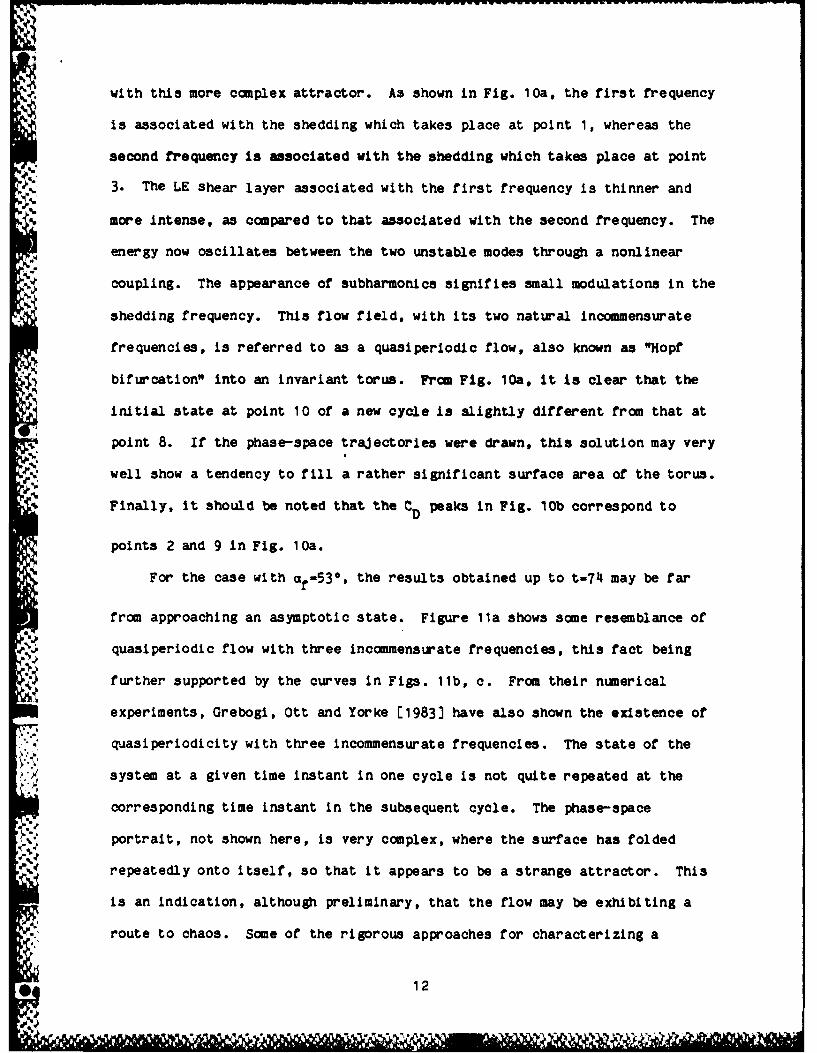
Awith this more complex attractor. As shown in Fig. 10a, the first frequency
is associated with the shedding which takes place at point 1, whereas the
second frequency is associated with the shedding which takes place at point
3. The LE shear layer associated with the first frequency is thinner and
more intense, as compared to that associated with the second frequency. The
energy now oscillates between the two unstable modes through a nonlinear
coupling. The appearance of subharmonics signifies small modulations in the
shedding frequency. This flow field, with its two natural incommensurate
frequencies, is referred to as a quasiperiodic flow, also known as "Hopf
bifurcation" into an Invariant torus. From Fig. 10a, it is clear that the
initial state at point 10 of a new cycle is slightly different from that at
point 8. If the phase-space trajectories were drawn, this solution may very
well show a tendency to fill a rather significant surface area of the torus.
Finally, it should be noted that the CD peaks In Fig. 10b correspond to
points 2 and 9 In Fig. 10a.
For the case with af- 5 3 *, the results obtained up to t-T4 may be far
from approaching an asymptotic state. Figure Ila shows some resemblance of
quasiperiodic flow with three incommensurate frequencies, this fact being
further supported by the curves in Figs. lib, c. From their numerical
experiments, Grebogi, Ott and Yorke E1983] have also shown the existence of
quasiperiodicity with three incommensurate frequencies. The state of the
system at a given time instant in one cycle is not quite repeated at the
corresponding time instant in the subsequent cycle. The phase-space
.: portrait, not shown here, is very complex, where the surface has folded
Vrepeatedly onto itself, so that it appears to be a strange attractor. This
is an indication, although preliminary, that the flow may be exhibiting a
route to chaos. Some of the rigorous approaches for characterizing a
* 12

strange attractor consist of the determination of i) the Lyapunov exponent;
(ii) the fractal dimension of the attractor, which is related to the number
of degrees of freedom; and finally, (iii) the Kolmogorov entropy. These
indices still need to be studied thoroughly in order to rigorously analyze
the route to chaos in a meaningful way.
The overall state of the total flow system was examined in terms of the
frequencies associated with the various sheddings and an invited paper based
on these results was presented by K. Ghia et al. [1985b]. A written version
of the paper was also prepared by K. Ghia et al. [1986].
Cambered Joukowski Airfoil
The 2-D unsteady flow analysis was continued for a cambered Joukowski
airfoil. A typical clustered conformal C-grid, with (230, 46) points, is
shown in Fig. 12 for the Gottingen 580 airfoil (i.e., an 11.8 percent thick
cambered Joukowski airfoil with a zero-lift angle of attack 0 -5.7110),
at effective flow angle of attack ae - 300.
Results are obtained for three flow configurations with Re 1 1000 and
ae a 5.7110, 150 and 300, the last two being in the stall and post-stall
flow regimes, respectively. Here, the effective angle of attack is
ae = af - mot with of being the geometric angle of attack between the chord
and the free-stream direction.
Figure 13 shows the inviscid starting solution, the grid distribution
in the near field and the steady-state stream-function and vorticity
contours for the case with Re - 1000 and ae " 5.7110. The stream-function
contours show a mildly separated region in the vicinity of the trailing edge
(TE). Laminar boundary layers prevail on both the suction and pressure
13
illaal M

surfaces, as observed in the vorticity contours, which also show a tongue-
like behavior. The streamwise extent of the separated flow near the TE is
0.15c, as compared to approximately 0.4c for the symmetric Joukowaki airfoil
with a - 50, as given by K. Ghia, Osswald and U. Ghia [1985b].e
The time history of the lift and drag coefficients CL and CD,
respectively, is depicted in Fig. 14 for the case with Re - 1000, e - 150.
A time asymptotic limit-cycle solution evolves by approximately t - 12, as
compared to t - 31 for the case of the corresponding symmetric airfoil.
K. Ghia et al. [1985b] had defined the period as the time interval required
for the L2-norm of the deviation of the instantaneous state of the flow from
a reference initial state to become smaller than a specified tolerance. For
the present configuration, the period is established by examining the
successive maxima of CL in Fig. 14. The period associated with this limit-
cycle (ordinary attractor) is 1.046 characteristic time units and the
corresponding Strouhal number Sf - fc (sin af )/U- 0.154; based on e, its
value is S - 0.247. The corresponding period for the symmetric airfoil ise
1.416 and S - 0.18. Hence, the effect of camber is to increase thee
frequency of the periodic shedding of large-scale vortices from the TE
region and from the separation zone on the suction surface.
The oefficients of lift C L and drag CD for the case with Re - 1000,
- 300 are shown in Fig. 15. These curves show that, even at t - 52, the
flow has not yet reached an asymptotic state. Also, these curves show that
one cycle consists of two TE sheddings. Thus, there are two shedding
frequencies associated with this attactor; these correspond to the sheddings
14

associated with points 1 and 2 in Fig. 15. The LE shear layer associated
with the first frequency is thinner and more intense as compared to that
associated with the second frequency. This flow field, with its two natural
incommensurate frequencies, is again referred to as a quasiperiodic flow.
The phase-space portrait is complex and is tending towards being a "strange
attractor". The corresponding Poincare sect n indicates that the attractor
may be a thin torus. These results are similar to those of the symmetric
airfoil (Fig. 11), except that the CL history appears more chaotic and does
not seem to be tending towards a limit cycle. Also, there is a peak due to
the shedding from the LE at point 3; this was not present in the results for
the symmetric airfoil. The time instants at which the detailed flow results
are presented correspond to the TE-LE-TE sheddings.
The instantaneous stream-function contours, presented in Figs.
16a,c,e,g,i, show massively separated flow, with large eddies present over
the suction surface as well as in the wake. Figures 16a,g,i show the
presence of multiple separations, whereas Fig. 16c shows the presence of two
counterclockwise co-rotating bubbles, aft of the shoulder, towards the TE
and these bubbles are in the process of coalescing. The corresponding
vorticity contours are shown in Fig. 16b,d,f,h,j and various vortex
interactions can be observed from this figure. In Fig. 16b, the TE vortex
has just been shed, a new TE vortex intensifies as shown in Fig. 16d and is
being Just separated from the TE by the growing LE vortex. Figure 16f
corresponds to shedding of the LE vortex. The state shown in Fig. 16J
corresponds to TE shedding and has features similar to those in Fig. 16b.
The results of this effort may be summarized as follows. Up to the
stall regime, camber causes the flow fields to be dominated by the TE
geometry. Also, the extent of the separated flow is diminished both in the
* 15

streamwise and the lateral dimensions and the shedding frequency isincreased. For flow fields in the post-stall regime, the CL time history
iL
becomes more chaotic and shows a peak associated with LE shedding. The
computation of the flow field needs to be continued to larger t, to predict
its further behaviour with definite assurance. A paper based on these
results was presented by Osswald et al. [1986) and appears in the Conference
Proceedings.
Circular Cylinder
For flow past airfoils at high angle of attack, the airfoil behaves
like a bluff body. The large-scale structure of the separated flow past a
bluff body, e.g., a circular cylinder, is not understood well, except at
extremely low values of the Reynolds number' Re around 120 where Re is based
on the cylinder diameter. The understanding of separated flow past the
model problem of a circular cylinder is crucial, as it may lead to a better
understanding of more complex flows such as separated flow past airfoils
with or without solution bifurcations associated with lift hysteresis,
symmetry breaking, etc. Also, a thorough knowledge of steady separated flow
could aid in analyzing unsteady separated flow leading to incipient
transition and, eventually, to chaos.
Hence, the flow past a circular cylinder was computed, first without
assuming symmetry. The instantaneous streamlines and vorticity contours are
presented in Fig. 17 for Re - 200. The occurrence of the bulge phenomenon
for Re - 200 and t k 1.0, first reported by Bouard and Coutanceau [19801, is
also computed satisfactorily. It leads to an alteration in the vorticity
contours close to the surface of the cylinder in the separated zone. For
the corresponding symmetric configuration with Re - 500, the instantaneous
* 164iP

stream-function and vorticity contours are delineated in Fig. 18 at t - 100,
225, 800 and 1600. The eddy length L, as seen from the stream-function
contours, increases from approximately 6 diameters at t - 100 to 27
diameters at t-1600; the asymptotic results of Fornberg [1985) show this
length to be 36 diameters. Further, the region between the cylinder and the
main eddy grows from about 1 diameter initially to 5 1/2 diameters by t -
1600; the corresponding asymptotic results of Fornberg [1985) show this
distance to be approximately 8 diameters. This region can be considered as
consisting of two parts: the front part where the separating streamline
grows in width as O(Re 11 2 ) followed by a 'transition' region in which the
growth rate adjusts such that the vidth can grow as O(Re) in the main eddy.
Also, in this transition region, the vorticity increases from zero to the
level of nearly uniform vorticity present in the main eddy. The kink in the
contours of the vorticity is conjectured to be related to this change in the
growth rate of the width of the eddy. The results for the velocity do not
show 0(0) thickness for both the shear layer past the center of the main
eddy and the return jet, as proposed by Smith [1985); the present results
need to-be scrutinized further to provide the accurate flow structure. The
Navier-Stokes calculations show that, near Re - 500, the translating
cylinder drags with it a massive eddy.
These results for flow past cylinder were presented by K. Ohia et al.
[1986) at the I.U.T.A.M. Conference; a written version of the paper is to
appear in the Conference volume.
2.4 Unsteady Three-Dimensional Navier-Stokes Analysis
The effort directed to this area of study was focused primarily on the
careful selection of the formulation of the governing partial differential
*17

equations and the proper choice of discretization to produce sparse matrices
with repetitive block structure. This structure is essential for efficiency
of the inversion technique with a high degree of vectorizability in the
solution phase. The goal was to develop a direct-solution technique for the
3-D unsteady Navier-Stokes equations for general geometries. This was based
on the fact that direct-solution methodology developed by the principal
investigators for 2-D unsteady Navier-Stokes equations has proved very
robust and efficient.
After much careful study, the velocity-vorticity (V,w) formulation has
been selected, as opposed to the primitive-variable (V,p) and the several
vector-potential-vorticity (A,:) formulations. All vector-potential
formulations, which include stream-like functions, toroidal and poloidal
potentials, etc., suffer from the necessity for more boundary conditions on
the vector potential A than are available naturally from the physics of the
flow problem. This difficulty can be traced to the fact that the vector
potential is gauge invariant and 'extra' boundary conditions are required to
uniquely select a specific gauge. Conversely, the non-physical boundary
conditions selected must be consistent with a specific gauge function;
otherwise, numerical convergence difficulties can be expected.
• ZAt first glance, the primitive-variable (V,p) formulation appears to be
computationally more efficient, since it requires the solution of only four
unknowns, V1, V2 , V3, and p, rather than the six unknowns, V1 . V2 , V3 , wit
W 29 and w 3 occurring in the velocity-vorticity (V,w) formulation. Indeed,
much effort has been directed by the technical community at primitive-
variable techniques for compressible flows. However, in the present effort,
18

it is determined that the velocity-vorticity (V,w) problem can be
d1scretized in such a manner as to produce a sparse matrix problem with
repetitive block structure. As a result, the computational work associated
with the implicit determination of one unknown can be effectively eliminated
from the solution of the velocity problem, while the computational effort
for yet another unknown can be eliminated from the vorticity-transport
equation. Consequently, velocity-vorticity techniques deserve attention.
A philosophical point to bear in mind is that the (V,u) formulation
leads to a more natural decoupling of the governing equations than occurs in
the primitive-variable technique. Specifically, pressure is an essential,
* nonlinear function of velocity, whereas vorticity is a linear function of
velocity. Indeed, the (V,;) formulation can physically separate the spin
dynamics of a fluid particle (vorticity-transport problem) from the
translational kinematics of the fluid particle (the elliptic velocity
problem). This natural decoupling, which occurs in the (V,;) formulation,
may be seen to directly translate into simple and direct application of the
necessary boundary conditions. Furthermore, complete internal consistency
can be maintained with the (V,_w) formulation, i.e., all integral vorticity
constraints, all integral velocity constraints, solenoidal velocity, etc.,
can be algebraically guaranteed, irrespective of grid size and time-step
discretization, throughout the entire flow solution.
Wu [1985] and his associates, Fasel [1976), and Gatsky, Groach and
Rose [1982) have used the corresponding 2-D (V,w) formulation and are
presently developing 3-D algorithms using the (V,w) formulation. The
present analysis, however, aims to employ efficient direct inversion for the
19
11 11 111 1- j 1

elliptic velocity problem which can be formulated so an to produce a
uniquely determined nonsingular vector-matrix problem with repetitive sparse
block structure.
2.5 Pressure-Field Evaluation for Urteady Flows
For unsteady flows analyzed using the (w, #) formulation of the Navier-
Stokes equations, the surface distribution of the pressure my be obtained
by simply integrating the tangential component of the lmmntum equation
along the surface. For determination of pressure in the total flow field,
1U. Ghia et al. [1976] have shown that a path-independent presure field
results only frm the solution of the Neumann-Poisaon pressure poblm
formed by the divergence of the mcmentu equations. With Neumann-type'..$
boundary conditions, this problem admits a solution, which is unique upto an
arbitrary additive constant, only when the boundary values and the source in
. the differential equation satisfy Green's interal theoram. This places
certain very specific requirements on the disoretization of the Neumann-
Poisson problem. This work is being pursued with the assistance of Collopy
[1986] and comprises his Master's deree thesis, expected to be completed
shortly. The application considered was the flow through an orifice in a
doubly infinite circular pipe. The infinite extent of the flow domain in
the streamwise direction necessitated additional considerations in order to
maintain bounldedness for the working variable for the pressure.
1/e 2.6 Supercomputer Usage and Graphical Post-Processing of Data,All of the research pursued towards this rant makes extremely
extensive use of computer resources. For acceptable productivity, all
available computer facilities are made use of, judiciously. During the
20

initial development stages, the programs are tested and run using the
facilities of the University of Cincinnati (UC); these include the Aerospace
Engineering Department's Perkin Elmer 3250 supermini computer system with
-1;. dual processors for parallel computation possibility and the UC Computer
Center's AMDAHL 470 V/7A mainframe facility. Host of the actual results are
eventually generated using the NASA-Lewis CRAY XMP supercomputer system for
the IPNS computations and the NASA-Langley CYBER 205 supercomputer system
for the unsteady Navier-Stokes computations (2-D as well as 3-D). All four
of these systems are equipped with their respective peripheral devices which
are employed for post-prooessing the results of the computations and for
presenting these results in suitable raphical form. All of the graphics
packages employed are written by the present research team and are very
2:. efficient. However, the retrieval of the large data bases from the remotely
located supercomputers is extremely inefficient via the present long-
distance communication network. Therefore, plans are presently underway to
• purchase, through AFOSR funds, a superworkstation and, through the
University of Cincinnati, have a leased direct-communication line to the
NASA-Langley supercomputer site; this is most essential for the 3-D unsteady
flow simulations, which are presently being pursued. The limited
availability of supercomputer time continues to create a great deal of
difficulties. Much valuable time is often expended In transferring programs
from one computing facility to another, in the hope of expediency, but this
necessitates continual changes in the programs and ends up consuming
additional personnel time. Easier availability of larger amounts of
supercomputer time would be most conducive for rapid progress in this
research.
21

REFERENCES
Bouard, R. and Coutanceau, M., (1980), "The Early Stage of Development ofthe Wake Behind an Impulsively Started Cylinder for 40 < Re < 10 ,"
Journal of Fluid Mechanics, Vol. 101, pp. 583-607.
Collopy, G.B., (1986), "Determination of Flow, Including DischargeCoefficients, in a Pipe-Orifice Using Unsteady Navier-Stokes Equations,"M.S. Thesis, Department of Aerospace Engineering and EngineeringMecanim, University of Cincinnati, in progress.
Gatski, T.B., Grosch, C.E. and Rose, M.E., (1982), "A Numerical Study of theTwo-Dimensional Navier-Stokes Equations in Vorticity-Velocity Variables,"Journal of Computational Physics, Vol. 48, No. 1, pp. 1-22.
Fasel, H., (1976), "Investigation of the Stability of Boundary Layers by aFinite-Difference Model of the Navier-Stokes Equations," Journal of FluidMechanics, Vol. 78, Part 2, pp. 355-383.
Fornberg, B., (1985), "Steady Viscous Flow Past a Circular Cylinder Up toReynolds Number 600," Journal of Computational Physics, Vol. 61, pp. 297-320.
Ghia, K.N. and Ghia, U., (1982), "Semi-Elliptic Globally-Iterative Analysisfor Two-Dimensional Subsonic Internal Flows," presented at NASA-LewisWorkshop on Computational Fluid Mechanics, Cleveland, Ohio, October 1982.
*Ghia, K.N., Qsswald, G.A. and Ghia, U. (1985a), "Analysis of Two-DimensionalIncompressible Flow Past Airfoils Using Unsteady Navier-StokesEquations," Proceedings of Third Symposium on Numerical and PhysicalAspects of Aerodynamic Flows, Long Beach, California.
Ghia, K.N., Osswald, G.A. and Ghia, U., (1985b), "Simulation of Self-InducedUnsteady Motion in the Near-Wake of a Joukowski Airfoil," presented atFirst Nobeyama Workshop on High-Re Computations, Nobeyama, Japan,September 1985.
Ghia, K.N., Ghia, U., Osswald, G.A. and Liu, C.A., (1986), "Simulation ofSeparated Flow Past a Bluff Body Using Unsteady Navier-StokesEquations," presented at I.U.T.A.M. Symposium on Boundary LayerSeparation, London, England, August 1986.
Ghia, K.N., Osswald, G.A. and Ghia, U., (1986), "Simulation of Self-InducedUnsteady Motion in the Near-Wake of a Joukowski Airfoil," Lecture Notesin Engineering, November 1986.
Ghia, U., Ghia, K.N. and Ramamurti, R., (1983), "Hybrid C-H Grids forTurbmachinery Cascades," Advances in Grid Generation, ASME Publication,June 1983.
Ghia, U., Ghia, K.N., Rubin, S.G. and Khosla, P.K., (1981), "Study ofSeparated Flow in a Channel Using Primitive Variables," InternationalJournal of Computers and Fluids, Vol. 9, pp. 123-142.
22

Ohia, U. and Goyal, R.K., (1976), "A Study of Laminar IncompressibleRecirculating Flfow in a Driven Cavity of Polar Cross Section,"Numerical/Laboratory/Cmputer Methods in Fluid Mechanics, ASMEPublication, 1976.
Ghia, U., Ramamurti, R. and Ghia, K.N., (1985), "A Semi-Elliptic Analysis ofInternal Viscous Flows," presented at First Nobeyama Workshop on High-ReCoputations, Nobeyama, Japan, September 1985.
Ghia, U., Ramamurti, R. and Ghia, K.N., (1986), "A Semi-Elliptic Analysis ofInternal Viscous Flows," Lecture Notes in Engineering, November 1986.
Grebogi, C., Ott, E. and Yorke, J.A., (1983), "Are Three-FrequencyQuasiperiodic Orbits to be Expected in Typical Nonlinear DynamicalSystems?" Physical Review Letters, Vol. 51, No. 5, pp. 339-342.
Osswald, G.A., Ghia, K.N. and Ghia, U., (1985), "An Implicit Time-MarchingMethod for Studying Unsteady Flow with Massive Separation," AIAA CP 854,pp. 25-37.
Osswald, G.A., Ghia, K.N. and Ghia, U., (1986), "Simulation of BuffetingStall for a Cambered Joukowki Airfoil Using a Fully Implicit Method,"presented at 10th ICNMFD, Beijing, China; to appear in Lecture Notes inPhysics, Editor: F.G. Zhuang, Springer Verlag, New York.
Smith, F.T., (1985), "A Structure for Laminar Flow Past a a Bluff Body atHigh Reynolds Number," Journal of Fluid Mechanics, Vol. 155, pp. 175-191.
Wu, J.C., (1985), "Computational and Theoretical Studies of Unsteady ViscousAerodynamics," Proceedings of Conference on Low Reynolds Number AirfoilAerodynamics, Notre Dame, Indiana.
23
,..N

SECTION 3
PAPERS AND REPORTS PUBLISHED
BOOKS AND MONOGRAPHS
Ghla, K.N. and Ghia, U., "Elliptic Systems: Finite-Difference Method,"Chapter in Handbook on Numerical Heat Transfer, Editors: W.J. Minkowyczet al., John Wiley and Sons, 1987.
Ghia, U. and Ghia, K.N., "Navier-Stokes Equations for Incompressible Flow,"Section of Chapter in Handbook of Fluids and Fluid Machinery, to bepublished in 1987.
Ghia, K.N., Osswald, G.A. and Ghia, U., "Analysis of Two-DimensionalIncompressible Flow Past Airfoils Using Unsteady Navier-StokesEquations," Chapter in Numerical and Physical Aspects of AerodynamicFlows: Vol. III, Editor: T. Cebeci, Springer-Verlag, New York,December 1986.
PAPERS AND REPORTS
Ghia, K.N., Ghia, U. and Shin, C.T., "Study of Asymptotic IncompressibleFlow in Curved Ducts Using a Multi-Grid Technique," to appear in Journal
of Fluids Engineering, June 1987.
Ghia, K.N., Ghia, U., Osawald, G.A. and Liu, C.A., "Simulation of SeparatedFlow Past a Bluff Body Using Unsteady Navier-Stokes Equations," toappear in Boundarl Layer Separation, Editors: F.T. Smith and S. Brown,North Holland, 1987.
Ghia, K.N., Ghia, U., Liu, C.A. and Osawald, G.A., "Study of Unsteady WakeBehind Circular Cylinder Using Time-Dependent Simulation," Bulletin ofthe American Physical Society, Vol. 31, No. 10, November 1986.
Osswald, G.A., Ghia, K.N. and Ghia, U., "Simulation of Buffeting Stall for aCambered Joukowski Airfoil Using a Fully Implicit Method," Lecture Notesin Physics, Editors: F.G. Zhuang and Y.L. Zhu, Vol. 264, pp. 516-522,Springer Verlag, 1986.
Ohia, K.N., Osswald, G.A. and Ghia, U., "Simulation of Self-Induced Motionin the Near"Wake of a Joukowski Airfoil," Lecture Notes in Eniineering;Editor: K. Kuwahara, Springer-Verlag, New York, November 1986.
Ghia, U., Ramamurti, R. and Ghia, K.N., "A Semi-Elliptic Analysis ofInternal Viscous Flows," Lecture Notes in Engineering; Editor: K.Kuwahara, Springer-Verlag, New York, September 1986.
24

Osawald, G.A., Ghia, K.N. and Ghia, U., "An Implicit Time-Marching Methodfor Studying Unsteady Flow with Massive Separation," AIAA CP 854, July1985.
MoGreehan, W.F., Ghia, K.N., Ghia, U. and Osswald, G.A., "Analysis ofSeparated Flow in a Pipe Orifice Using Unsteady Navier-StokesEquations," Lecture Notes in Physics, Edited by Soubaramnayer and J.Boujot, Vol. 21B, p. 393-, 1985.
256

SECTION 4
SCIENTIFIC INTERACTIONS - SEMINARS AND PAPER PRESENTATIONS
SEMINARS AND INVITED LECTURES
Ghia, K.N., Ghia, U., Osswald, G.A. and Liu, C.A., "Simulation of SeparatedFlow Past a Bluff Body Using Unsteady Navier-Stokes Equations,"presented at I.U.T.A.M. Symposium on Boundary Layer Separation, London,England, August 1986.
Ghia, K.N., "Simulation of Self-Excited, Vortex Dominated MassivelySeparated Viscous Flow Using Unsteady Navier-Stokes Equations,"presented at University of Southern California, Los Angeles, California,July 1986.
Ghia, K.N., "Study of Unsteady Self-Excited Massively Separated Flows,"presented at Georgia Institute of Technology, Atlanta, Georgia, May1986.
Ghia, K.N., "Study of High-Incidence Vortex Dominated Flows," presented atRockwell International Science Center, Thousand Oaks, California,January 1986.
G.,iia, K.N., "Two-Dimensional and Axisymmetric Self-Excited OscillatorySeparated Viscous Flows," presented at Indian Institute of Technology,Bombay, India, September 1985.
Ghia, K.N. and Ghia, U., "Navier-Stokes Solutions of Some Low-Speed ViscousFlows," presented at Institute for Computational Fluid Dynamics, Tokyo,Japan, September 1985.
Ghia, K.N., "Simulation of Self-Induced Motion in the Near-Wake of aJoukowski Airfoil," presented at First Nobeyama Workshop on HighReynolds Number Flow Computations, Nobeyama, Japan, September 1985.
Ghia, K.N., "On an Adaptive Grid Technique and Simulation of High ReynoldsNumber Flows Using Fully Implicit Technique," presented at ICASE, NASALangley Research Center, Hampton, VA, August 1985.
Ghia, K.N., "On High Curvature Resolution Problems in Adaptive Grid andBifurcation Solutions in Viscous Flows," presented at SupersonicComputational Fluid Dynamics Branch, NASA Langley Research Center,Hampton, VA, August 1985.
Ghia, U., "Inclusion of Upstream Influence in Parabolized Navier-StokesEquations for Low-Speed Viscous Flows with Complex Geometry," presentedat University of Southern California, Los Angeles, California, July1986.
Ghia, U., "Study of Viscous Flow Problems with Complex Geometry, Using anInteracting Parabolized Navier-Stokes Analysis," presented at GeorgiaInstitute of Technology, Atlanta, Georgia, May 1986.
26

Ghia, U., "Analysis of Flows in Twrbomachinery Applications Using anInteracting Parabolized Navier-Stokes Formulation," presented at IndianInstitute of Technology, Bombay, India, September 1985.
Ghia, U., "Interacting Parabolized Navier-Stokes Formulation," presented atICASE, NASA-Langley Research Center, Hampton, VA, August 1985.
Ghia, U., "Analysis of Turbulent Boundary Layer Flow over RoughenedSurfaces," presented at Supersonic Computational Fluid Dynamics Branch,NASA-Langley Research Center, Hampton, Virginia, August 1985.
PAPER PRESENTATIONS
Liu, C., Ghia, K.N., Ghia, U. and Osswald, G.A., "On Unsteady Viscous FlowPast a Circular Cylinder," presented at AIAA 12th Annual Mini-Symposiumon Aerospace Science and Technology, WPAFB,Ohio, March 1986.
Osswald, G.A., Ohia, K.N. and Ghia, U., "Unsteady Navier-Stokes Analysis ofViscous Flow Past a Cambered Joukowski Airfoil," presented at AIAA 12thAnnual Mini-Sympozium on Aerospace Science and Technology, WPAFB, Ohio,March 1986.
Osawald, G.A, Ghia, K.N. and (This, U., "Simulation of Buffeting Stall for aCambered Joukowski Airfoil Using a Fully Implicit Method," presented atTenth International Conference on Nuerical Methods in Fluid Dynamics,Beijing, China, June 1986.
Ramamrti, R., Ghia, U. and Ghia, K.N., "Hybrid C-H Grids and a Semi-Elliptic Solution Of Viscous Flow for Cascades," In AIAA Paper 85"1535,July 1985.
27

SECTION 5
STUDENT THESES AND DISSERTATIONS
M.S. DEGREE THESES
Collopy, G.B., "Determination of Flow Including Discharge Coefficients, In aPipe-Orifice Using Unsteady Navier-Stokes Equations," M.S. Thesis,
Department of Aerospace Engineering and Engineering Mechanics,University of Cincinnati, Cincinnati, Ohio, August 1987.
Liu, C.A., "Study of a Two-Dimensional Viscous Flow Past a Circular Cylinder
Using Unsteady Navier-Stokes Equations," M.S. Thesis, Department of
Aerospace Engineering and Engineering Mechanics, University ofCincinnati, Cincinnati, Ohio, August 1987.
Ph.D. DEGREE DISSERTATIONS
Ramamurti, R., "A Semi-Elliptic Analysis and Hybrid C-H Grids for Two-Dimensional Viscous Flow Through Cascades," Ph.D. Dissertation,Department of Aerospace Engineering and Engineering Mechanics,University of Cincinnati, Cincinnati, Ohio, August 1986.
28

AFIG. 1. H-GRID FOR TURBINE CASCADE WITH
'S* ROUNDED LEADING EDGES.
H
KXL
C-RDHYBRID GRID SU-REGION BOUNDARIES r
FOR HYBRID GRID
Ij'
FIG. 2. HYBRID C-H GRID FOR CASCADE -PATCHED SOLUTION.
29

4A
HYBRID GRID FOR SUB-REGION BOUNDARIESSTAGGERED CASCADE
.5
'P L A
Cl
L, o
D"
COMPTATONA DOAI
FIG. 3. ~~~~~COMPUTATIONAL DOMAIN (-)FRHBI RDFRHGL
STAGGERED CASCADE.
30

At
FIG. 4. SUB-REGION BOUNDARIESFOR HYBRID GRID.
I
CO O . / A L cO FO A'
em-e
L $
COPUTATIONAL REGION FOR
r.-pLIclrT -soX "N VP AI%C •
... COMPUTATIONAL REGION P01 I= r,-INPLICZT "OL TON STEP
FIG. 5. 2-D COMPUTATIONAL REGIONS FOR APPLICATION OF ADI SCHEME TOHYBRID GRID FOR COMPOSITE SOLUTION.
31

b 0 P 9.20 9. 94
0.3 3.2 3.3
y y.
9.3 .00
3 25 so X 7 0li 27 a0 3 St 3 32
ENLARGED HORIZON1TAL SCALESURFACE PRESSURE DISTRIBUTION
30
fully ucntt22 developed
GEOMETRY ANDINFLOW AND OUTFLOW BOUNDARY CONDITIONS
27 26 29 x33 31 32
SURFACE SHEAR PARAMETER
FIG. 6. RESULTS FOR SYMMETRIC CHANNEL WITH EXPONENTIAL CONSTRICTION;Re a 1500, t~ /h - 0.2, (201 x 61) GRID.
ma
32

9.2 teeRe 0 1.5x10³
A 3.1x10³ Re 1.5x10³
" 13 7 a 3.1x10
3
91a 6.3x10Re 39"1 --* 1.1x10 4 d a63z1034
SB* 1.1X1O0
1T 0 1.5x10 4Pb "_
259.0 -
- ---------------------- L
S -9.1 -2 5
9 li x 11 12 19.9 19.5 11.a 11.5
FIG. 7. MEUL7S FOR FLAf'PLATE CASCADE FOR VARIOUS REYNOLDS NUMBERS.(186 71) GRID.
9.3 lee t am /c
o .059.2 75 .075
* .19.1 591
S.. 25
-P . U .1
1t 11 12 .8 14.5 11.8 11 .5x X
FIG. Sa. RESULTS FOR SYMMETRIC CASCADE OF PARABOLIC AIRFOILSFOR VARIOUS tmax /a; Re m 1500, (186 x 71) GRID.
33

& 3.1 WO 7 * S1
a 6.3z103 & 3.1X10³
4 a 6.3xdO 3
*b I1XlO * 1W
FO VAROU IXTNMD /a 6. 0.5(9 1). am .5
'pp
9 @*Evian @I
I *l91? 91Is 6.3194K @I
96 @.Doss" I I
1i 6. MM0 I I
a, 6362K @I
rt(;. ~ ~ ~ ~ ~ ~ ~ ~ ~ ~ a s.o.19 IIm ormrtsym i ~Ago PRN IFISt~~~ ~ ~ ~ 6.394? /aU00tN .4,f 900
a3481366

0.e 00(b)
g~% 0.1.
I-I
.4 0.8(
e~g S0 90
6.0 *
1.3I
0.1
eg0.4.0-.
Fig. 9. Instantaneous Aerodynamic Coefficients at Re a 1,000, a 150.
(a) Lift CL 0 (b) 'Drag C D Cc() Moment C M, - Symmewtric
Joukowaki 'Airfoil.
* ue.e u~ ge~ * .m~(b)
6 % am)'" 8'0 (,a)
CS UU *I I000* .W 0 i l ll* 1. - -1+(1)
., 0.0
Jouow"A"/W~/l
IIII o.e
. .
1.4
I.e IV C1.9 0.1
1. 10. Instantaneous Aerodynamic Coefficients at Re w 1.0go, a t 30e .
(a) Lift CLv (b) Drag CD, (c) Moment CI I . - SymmetricJouIowsid Airfoil.
35
I I I I i I I I I

i" * R " sm (b)
3.2
LI3.6
LS
IL4IAla.,
3.8
3.4
LI
IIJ 12 •.
8.,
a-,..,.- ... a
ILI
&k4
8.01.9
$.4
,..a.. ,.i. ,m (a)
1.8
a. O . . . . . . . . . . . . .£. . .
LIw
a..l
a."a
IFig. lL1 Instantaneous Aerodynamic Coefficients at Re 1 ]L000, of 5 3 °0 .
(a) Lift CL , (b) Drag C D # (c) Moment C M , SymmetricJoukowsid Airfoil.
36
II !1 II I I ! II I~~~~~1.I15 1i IIrl'fl i II l'

ag .4-B * f ~ .. 1 5h . 4 9.2090 - is*
0. .41 as - 1000
3.3
M3 4
Mg 4 Lift and Da. Hitris atte 580. TOM
t 0 Grid Distribution
no an.
46
Fi .1 a.ti e 580 atRe-100 a e 5710 at t 0 Iv i Stream
3 LO
4.W
443
w
GO
Fig... 13OSIM Moosttlngen 580 a ea ~ *571 tt-0 nlcdSra
Fucto adGrdDitibton t -1.0SeayStt Sltin

1 (a) ma1(b)
%lo am&* =-,m3 *rd m.
&a P_ L
0.1m ma p~ *
e
9.0ma
Re ma Iff aa 300
38mu
%d- h *wm

--m
t%. 1. 5,244-)t 15 m 35.87091
c) t -2.0, -2.3933 ;d) t -2.0, u 34.53603.... 4
:4e
0b
e) t.- 2.5, ,2.3726 f) t ,2.5, - 33.5096
g) t. 1.0, q "2.3526 h) t-3.0,. w,,z "32.68463
g"A
av 0. 05 1 w -1.0, mml"50.0, A 2 w 10.0
INSTANTAN/EOUS STREAM-FUN CTIOI( COTOURS VORTICITY COTOURS
FIG. 17 DEVELOPMENT 0 r now PAST CYLINDER AT Re a 200; SYMMETRY NOT ASSUMED,
39
I - I - + " "' ' + + I + -bIe

C4C
Mt CA * -
1 .0
0 10C*4
a 0 0 n N.
ad 0
400 U3.
.0 40
-3IKNMMXM

It1S)C