Embed Size (px)
Citation preview
Mar Cor PurificationWRO 300 HOperator’s Manual
Important User InformationCopyright © 2016 by Mar Cor Purification, Inc.
All rights reserved. No part of the contents of this manual may be reproduced, copied, or transmitted in any form or by any means including graphic, electronic, or mechanical methods or photocopying, recording, or information storage and retrieval systems without the written permission of the publisher, unless it is for the purchaser's personal use.
The information in this manual is subject to change without notice and does not represent a commitment on the part of Mar Cor Purification (MCP). MCP does not assume any responsibil-ity for any errors that may appear in this manual. In no event will MCP be liable for technical or editorial omissions made herein, nor for direct, indirect, special, incidental, or conse-quential damages resulting from the use or defect of this man-ual.
The information in this document is not intended to cover all possible conditions and situations that might occur. The end user must exercise caution and common sense when install-ing, using, or maintaining MCP products. If any questions or problems arise, call MCP Technical Services at 1-800-633-3080.
Intended UseMCP products are intended to be installed and used as described in this manual and other related MCP literature.
WRO 300 H
P/N 3027436 Rev
Table of Contents
Table of ContentsImportant User Information . . . . . . . . . . . . . . . . . . . . . . . 2Intended Use. . . . . . . . . . . . . . . . . . . . . . . . . . . . . . . . . . 2
Table of Contents . . . . . . . . . . . . . . . . . . . . . . . . . . . . . . . . 3
Preface . . . . . . . . . . . . . . . . . . . . . . . . . . . . . . . . . . . . . . . . 5Other Manuals for WRO 300 H. . . . . . . . . . . . . . . . . . . . 5Definitions of Expressions in the Manual . . . . . . . . . . . . 5Safety Considerations. . . . . . . . . . . . . . . . . . . . . . . . . . . 5List of Symbols . . . . . . . . . . . . . . . . . . . . . . . . . . . . . . . . 6Certification Marks . . . . . . . . . . . . . . . . . . . . . . . . . . . . . 8IPR - Intellectual Property Rights . . . . . . . . . . . . . . . . . . 8
Copyright . . . . . . . . . . . . . . . . . . . . . . . . . . . . . . . . . . 8Trademarks . . . . . . . . . . . . . . . . . . . . . . . . . . . . . . . . 8Manufacturer . . . . . . . . . . . . . . . . . . . . . . . . . . . . . . . 8
Introduction . . . . . . . . . . . . . . . . . . . . . . . . . . . . . . . . . . . . 9Intended Use. . . . . . . . . . . . . . . . . . . . . . . . . . . . . . . . . . 9General . . . . . . . . . . . . . . . . . . . . . . . . . . . . . . . . . . . . . . 9Alarm Types . . . . . . . . . . . . . . . . . . . . . . . . . . . . . . . . . 10
Notification. . . . . . . . . . . . . . . . . . . . . . . . . . . . . . . . 10Info. . . . . . . . . . . . . . . . . . . . . . . . . . . . . . . . . . . . . . 10Alarm . . . . . . . . . . . . . . . . . . . . . . . . . . . . . . . . . . . . 10Stop . . . . . . . . . . . . . . . . . . . . . . . . . . . . . . . . . . . . . 10
Conductivity Monitoring. . . . . . . . . . . . . . . . . . . . . . . . . 10Conductivity Notification (set at 20 μS/cm) . . . . . . . 10Conductivity Alarm (set at 30 μS/cm) . . . . . . . . . . . 11Conductivity Stop (set at 60 μS/cm) . . . . . . . . . . . . 11Setting of Conductivity Limits . . . . . . . . . . . . . . . . . 11Low Rejection Rate Notification. . . . . . . . . . . . . . . . 11
Mains Power Switch . . . . . . . . . . . . . . . . . . . . . . . . . . . 12Operator Panel . . . . . . . . . . . . . . . . . . . . . . . . . . . . . . . 12
Description of Buttons . . . . . . . . . . . . . . . . . . . . . . . 12Description of Indications . . . . . . . . . . . . . . . . . . . . 13Definition of Flash Indications . . . . . . . . . . . . . . . . . 13Reminders . . . . . . . . . . . . . . . . . . . . . . . . . . . . . . . . 14Operational Data . . . . . . . . . . . . . . . . . . . . . . . . . . . 14
Operation . . . . . . . . . . . . . . . . . . . . . . . . . . . . . . . . . . . . . 15Start . . . . . . . . . . . . . . . . . . . . . . . . . . . . . . . . . . . . . . . 15Stop. . . . . . . . . . . . . . . . . . . . . . . . . . . . . . . . . . . . . . . . 15
Regular Maintenance . . . . . . . . . . . . . . . . . . . . . . . . . . . . 17Heat Disinfection. . . . . . . . . . . . . . . . . . . . . . . . . . . . . . 17
Heat Disinfection Procedure . . . . . . . . . . . . . . . . . . 17
. D 3
Table of Contents
4
WRO 300 H
Stop Heat Disinfection Sequence . . . . . . . . . . . . . . 18Chemical Disinfection . . . . . . . . . . . . . . . . . . . . . . . . . . 18
Approved Chemical Disinfectants . . . . . . . . . . . . . . 19Test Kit Example . . . . . . . . . . . . . . . . . . . . . . . . . . . 19Chemical Disinfection Procedure . . . . . . . . . . . . . . 19Residual Test After Chemical Disinfection . . . . . . . 23Central Chem . . . . . . . . . . . . . . . . . . . . . . . . . . . . . 24
Cleaning . . . . . . . . . . . . . . . . . . . . . . . . . . . . . . . . . . . . 24Warm Acid Cleaning . . . . . . . . . . . . . . . . . . . . . . . . 24Alkaline Cleaning. . . . . . . . . . . . . . . . . . . . . . . . . . . 25Cleaning Procedure. . . . . . . . . . . . . . . . . . . . . . . . . 25Test for Residuals . . . . . . . . . . . . . . . . . . . . . . . . . . 25
Long Term Storage . . . . . . . . . . . . . . . . . . . . . . . . . . . . 26Preservation . . . . . . . . . . . . . . . . . . . . . . . . . . . . . . 26Rinse After Preservation . . . . . . . . . . . . . . . . . . . . . 26Check for Complete Rinse-out . . . . . . . . . . . . . . . . 27
Flush . . . . . . . . . . . . . . . . . . . . . . . . . . . . . . . . . . . . . . . 27Manual Flush . . . . . . . . . . . . . . . . . . . . . . . . . . . . . . 27Auto Flush . . . . . . . . . . . . . . . . . . . . . . . . . . . . . . . . 27
Exterior Cleaning . . . . . . . . . . . . . . . . . . . . . . . . . . . . . 27
Technical Data . . . . . . . . . . . . . . . . . . . . . . . . . . . . . . . . . 29Performance and Specification . . . . . . . . . . . . . . . . . . . 29Chemical Disinfection and Cleaning . . . . . . . . . . . . . . . 33Physical Data . . . . . . . . . . . . . . . . . . . . . . . . . . . . . . . . 33Materials Contacting Product Water . . . . . . . . . . . . . . . 34Environmental Data . . . . . . . . . . . . . . . . . . . . . . . . . . . 34Electromagnetic Environment . . . . . . . . . . . . . . . . . . . . 35Safety . . . . . . . . . . . . . . . . . . . . . . . . . . . . . . . . . . . . . . 38
Troubleshooting . . . . . . . . . . . . . . . . . . . . . . . . . . . . . . . . 39Alarms and Notifications . . . . . . . . . . . . . . . . . . . . . . . . 39
General . . . . . . . . . . . . . . . . . . . . . . . . . . . . . . . . . . 39Operation. . . . . . . . . . . . . . . . . . . . . . . . . . . . . . . . . 40Heat . . . . . . . . . . . . . . . . . . . . . . . . . . . . . . . . . . . . . 41Chemical, Cleaning, Rinse and Preservation . . . . . 42
Boot Loader . . . . . . . . . . . . . . . . . . . . . . . . . . . . . . . . . 44
Check List . . . . . . . . . . . . . . . . . . . . . . . . . . . . . . . . . . . . . 45
Index . . . . . . . . . . . . . . . . . . . . . . . . . . . . . . . . . . . . . . . . . 47
P/N 3027436 Rev. D
WRO 300 H
P/N 3027436 Rev
Preface
PrefaceThis manual provides the information needed to operate the WRO 300 H water purification unit.
Other Manuals for WRO 300 HThe list below shows all manuals related to this Operator’s Manual.
Definitions of Expressions in the Manual
Safety Considerations
Valid program version 4.x
Service Manual WRO 300/300 H, 3027437
Installation Guide WRO 300/300 H, 3027502
WARNINGIs used to alert the user not to take a certain action, which if taken can cause a potential hazard and result in a serious adverse reaction, injury or death. A warning may also be used to alert the user to take a certain action to avoid the potential hazard as above.
CAUTIONIs used to alert the user/operator to take a certain action to protect against a potential hazard which, if ignored, could have an adverse effect on the patient or the device. A caution may also be used to alert the user not to take a certain action to avoid the potential hazard as above.
NOTEA reminder to the user on normal treatment activity and on what is a suitable action in a particular situation.
WARNINGUnauthorized installation, modifications, alterations or repair of the WRO 300 H may result in malfunctioning or have other serious consequences for the safe operation of the equip-ment.
WARNINGDialysis machines that are supplied with water from the WRO 300 H water purification unit must comply with IEC 60601-2-16.
. D 5
Preface
6
WRO 300 H
List of Symbols
CAUTION• WRO 300 H may be operated only by persons who have studied
the instructions in these manuals and the manual for the dialysis monitor. If the system does not perform as described in this man-uals, it should not be used until the condition is rectified.
• The operator should pay attention to alarms and follow the instructions, warnings, cautions and notes given in the manual.
• The WRO 300 H will perform as designed only if it is used and maintained in accordance with MCP´s written instructions. Any warranties made by MCP with respect to the WRO 300 H are voided if the equipment is not used in accordance with the written instructions provided. MCP will not accept responsibility for any damage or injury resulting from improper use or maintenance or unauthorized repair.
• The use of mobile telephones or communication equipment in the vicinity of the WRO 300 H could adversely influence the per-formance of the machine. See specification.
• The WRO 300 H is not suitable for use in the presence of a flam-mable anesthetic mixture with air or with oxygen or nitrous oxide.
• WRO 300 H needs special precautions regarding EMC and needs to be installed and put into service according to the EMC information provided in the Operator’s and Service manual.
• U.S. Federal law restricts this device to sale by or on the order of a physician.
NOTE• During transportation and storage the equipment must be kept in its orig-
inal packing. If transportation or storage time is more than 15 weeks the environmental data relating to the operation must be followed.
• For the qualified technician the WRO 300/300 H Service Manual is avail-able. The Service Manual provides all of the necessary information for the safe and required maintenance of the machine.
• The WRO 300 H is intended for continuous operation.• The WRO 300 H has a feature called Low Flow Heat that is used in con-
junction with certain dialysis machines. This feature is not approved in the US by the FDA or currently compatible with any US dialysis machines.
Alternating current
Protective earth (ground)
Warning, consult accompanying documents
Off (power, disconnection from the mains)
P/N 3027436 Rev. D
WRO 300 H
P/N 3027436 Rev
Preface
On (power, connection to the mains)
Type B, applied part
Handle with care
This way up
Keep dry
Separate collection for electrical and electronic equipment
Input /Output
Year of manufacturing
The WRO 300 H is protected against dripping water
Recycling symbol -General
Reject water connection
Feed water inlet connection
Loop connections (Product water outlet and return)
ME equipment and ME systems that include RF transmit-ters or that intentionally apply RF electromagnetic energy for diagnosis or treatment shall be labeled with this sym-bol.
CB
. D 7
Preface
8
WRO 300 H
Certification Marks
IPR - Intellectual Property Rights
Copyright© 2016 Mar Cor Purification, Inc.
Trademarks• DIALOX® is a trademark registered in several countries, including
Sweden, United Kingdom and Japan by their respective owners• MINNCARE® is a trademark of Minntech registered in several
countries including United States and United Kingdom• MINNCLEAN® is a trademark of Minntech registered in several
countries including the United States• STERICHECK® is a trademark registered in several countries
including the United States and Japan by their respective owners• ULTRASIL® is a trademark of Ecolab registered in several coun-
tries including Australia and Canada
ManufacturerMar Cor Purification, Inc.14550 28th Avenue NorthPlymouth, MN 55447USAPhone: 1-800-633-3080Fax (Customer Service): 1-763-210-3868www.mcpur.com
The CSA(C-US) mark indicates that the WRO 300 H water purification unit conforms to the requirements related to safety of medical devices for the US and Can-ada. The C and the US adjacent to the CSA mark indi-cates that the WRO 300 H water purification unit has been evaluated to the applicable ANSI/UL and CSA standards for use in the US and Canada.
P/N 3027436 Rev. D
WRO 300 H
P/N 3027436 Rev
Introduction
1 Introduction
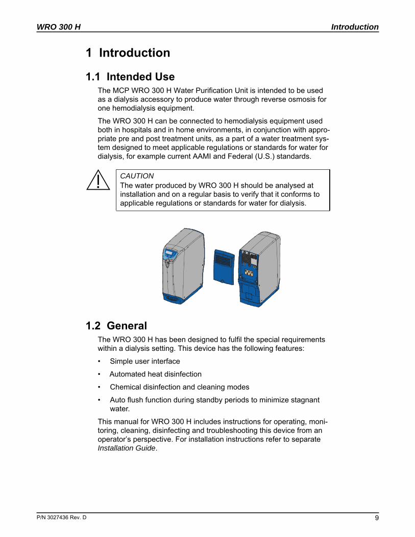
1.1 Intended UseThe MCP WRO 300 H Water Purification Unit is intended to be used as a dialysis accessory to produce water through reverse osmosis for one hemodialysis equipment.
The WRO 300 H can be connected to hemodialysis equipment used both in hospitals and in home environments, in conjunction with appro-priate pre and post treatment units, as a part of a water treatment sys-tem designed to meet applicable regulations or standards for water for dialysis, for example current AAMI and Federal (U.S.) standards.
1.2 GeneralThe WRO 300 H has been designed to fulfil the special requirements within a dialysis setting. This device has the following features:
• Simple user interface
• Automated heat disinfection
• Chemical disinfection and cleaning modes
• Auto flush function during standby periods to minimize stagnant water.
This manual for WRO 300 H includes instructions for operating, moni-toring, cleaning, disinfecting and troubleshooting this device from an operator’s perspective. For installation instructions refer to separate Installation Guide.
CAUTIONThe water produced by WRO 300 H should be analysed at installation and on a regular basis to verify that it conforms to applicable regulations or standards for water for dialysis.
. D 9
Introduction
10
WRO 300 H
1.3 Alarm Types
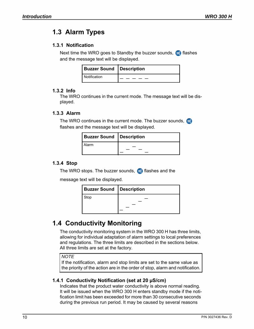
1.3.1 NotificationNext time the WRO goes to Standby the buzzer sounds, flashes and the message text will be displayed.
1.3.2 InfoThe WRO continues in the current mode. The message text will be dis-played.
1.3.3 AlarmThe WRO continues in the current mode. The buzzer sounds, flashes and the message text will be displayed.
1.3.4 StopThe WRO stops. The buzzer sounds, flashes and the
message text will be displayed.
1.4 Conductivity MonitoringThe conductivity monitoring system in the WRO 300 H has three limits, allowing for individual adaptation of alarm settings to local preferences and regulations. The three limits are described in the sections below. All three limits are set at the factory.
1.4.1 Conductivity Notification (set at 20 μS/cm)Indicates that the product water conductivity is above normal reading. It will be issued when the WRO 300 H enters standby mode if the noti-fication limit has been exceeded for more than 30 consecutive seconds during the previous run period. It may be caused by several reasons
Buzzer Sound DescriptionNotification
Buzzer Sound DescriptionAlarm
Buzzer Sound DescriptionStop
NOTEIf the notification, alarm and stop limits are set to the same value as the priority of the action are in the order of stop, alarm and notification.
P/N 3027436 Rev. D
WRO 300 H
P/N 3027436 Rev
Introduction
such as incipient fouling, degradation of the RO membrane or change in the feed water quality.
1.4.2 Conductivity Alarm (set at 30 μS/cm)The clinic's predefined maximum product water conductivity for water for dialysis has been exceeded for more than 30 consecutive seconds. An audible and visual alarm will be issued. The WRO 300 H will con-tinue operation to allow for finishing the dialysis treatment. The buzzer can be muted indefinitely by pressing , or . The button remains lighted to indicate that the alarm persists.
1.4.3 Conductivity Stop (set at 60 μS/cm)The clinic's predefined maximum permissible product water conductiv-ity has been exceeded for more than 30 consecutive seconds. An audible and visual alarm will be issued and WRO 300 H will stop. The alarm can be acknowledged by pressing , or . The WRO 300 H can be restarted. The alarm will reappear and the WRO 300 H will stop after 30 seconds if the conductivity remains over the limit.
1.4.4 Setting of Conductivity Limits• If the intention is to have an early warning of a change in the prod-
uct water conductivity, set the notification limit at a value between the normal product water reading and the set alarm limit.
• If the intention is to stop operation in case of a conductivity alarm, set alarm and stop limits to the same value.
• If, in case of a conductivity alarm, the intention is to allow for con-tinued dialysis in order to finish the ongoing dialysis treatment, set the alarm limit at the desired limit. The stop limit at which the WRO 300 H will stop then has to be set at a higher value.
To adjust the limits, refer to the Service Manual.
1.4.5 Low Rejection Rate NotificationThe rejection rate is the reduction (in percent) of the conductivity of the water in a reverse osmosis system. It depends on a number of factors such as conductivity, pH and temperature of the feed water and may vary significantly from one location to the other. It should therefore not be considered as an absolute measure of the quality of the water but rather as an indicator that can help to detect changes in performance of the WRO 300 H which may be caused by incipient fouling or degra-dation of the RO-membrane.
The low rejection rate notification default setting of 90 percent is rele-vant for most inlet water supplies. It may, however, need to be
NOTEIf the feed water conductivity is known to vary significantly, the con-ductivity notification limit should be inactivated by setting it at the same value as the conductivity alarm, see below.
. D 11
Introduction
12
WRO 300 H
adjusted at installation to a lower value by a qualified technician to fit local conditions, especially in cases of low feed water conductivity (<100 μS/cm). The limit should be set at least 5 percent lower than the initial value recorded at installation.
The low rejection rate notification will be displayed when the WRO 300 H enters standby if the set limit has been exceeded for more than 5 consecutive minutes during the previous run period.
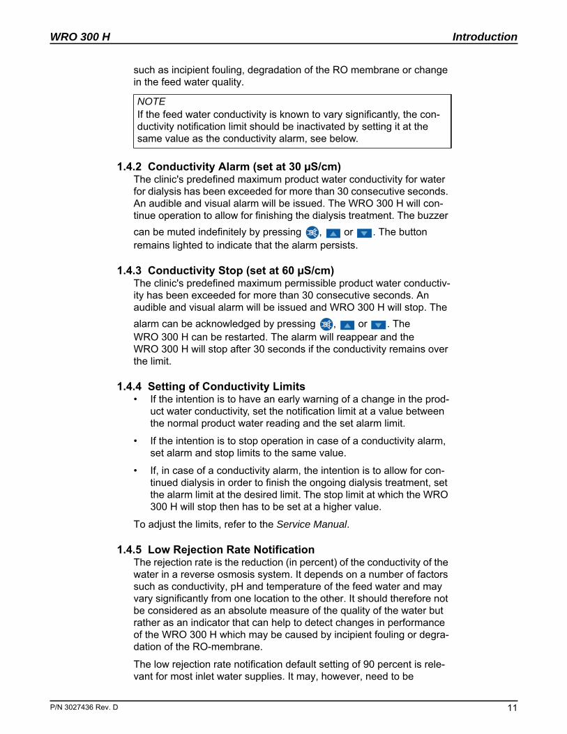
1.5 Mains Power SwitchThe mains power switch is only used in service situations to turn off the power. The mains power switch is located on the rear side behind a detachable cover.
1.6 Operator Panel
1.6.1 Description of Buttons
Buttons Description
Press to start operation (RUN).
Press to stop operation (STANDBY).
Press to stop heat disinfection procedure and low flow heat.
Press to enter SELECT (only in Standby mode)
Press to start the selected procedure (SELECT or CHEM SELECT).
Press during the chemical intake procedure to pause.
Press during dwell period to initiate rinse.
Press to silence audible alarms.
Press to unlock the display and enter the alarm list.
Mains power switch
P/N 3027436 Rev. D
WRO 300 H
P/N 3027436 Rev
Introduction
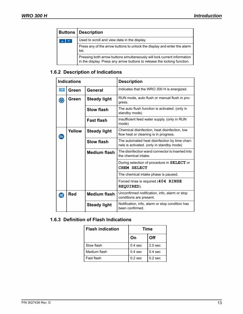
1.6.2 Description of Indications
1.6.3 Definition of Flash Indications
Used to scroll and view data in the display.
Press any of the arrow buttons to unlock the display and enter the alarm list.
Pressing both arrow buttons simultaneously will lock current information in the display. Press any arrow buttons to release the locking function.
Indications Description
Green General Indicates that the WRO 300 H is energized.
Green Steady light RUN mode, auto flush or manual flush in pro-gress.
Slow flash The auto flush function is activated. (only in standby mode)
Fast flash Insufficient feed water supply. (only in RUN mode)
Yellow Steady light Chemical disinfection, heat disinfection, low flow heat or cleaning is in progress.
Slow flash The automated heat disinfection by time chan-nels is activated. (only in standby mode)
Medium flash The disinfection wand connector is inserted into the chemical intake.
During selection of procedure in SELECT or CHEM SELECT
The chemical intake phase is paused.
Forced rinse is required (404 RINSE REQUIRED).
Red Medium flash Unconfirmed notification, info, alarm or stop conditions are present.
Steady light Notification, info, alarm or stop condition has been confirmed.
Flash indication Time
On OffSlow flash 0.4 sec 2.0 sec
Medium flash 0.4 sec 0.4 sec
Fast flash 0.2 sec 0.2 sec
Buttons Description
. D 13
Introduction
14
WRO 300 H
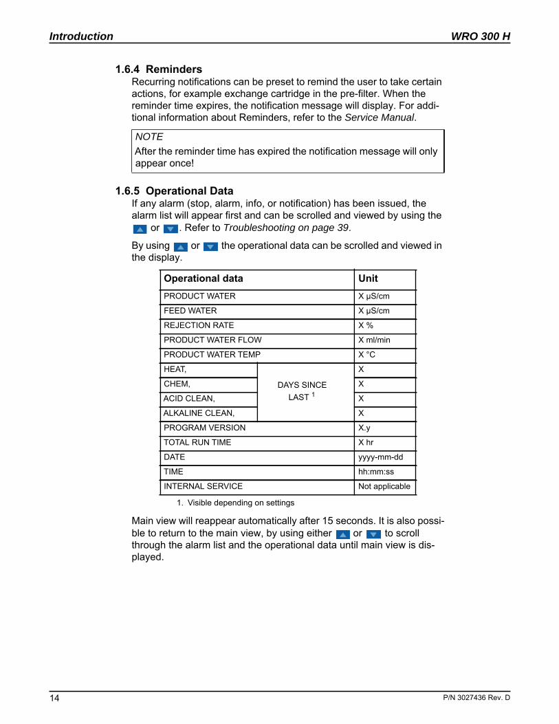
1.6.4 RemindersRecurring notifications can be preset to remind the user to take certain actions, for example exchange cartridge in the pre-filter. When the reminder time expires, the notification message will display. For addi-tional information about Reminders, refer to the Service Manual.
1.6.5 Operational DataIf any alarm (stop, alarm, info, or notification) has been issued, the alarm list will appear first and can be scrolled and viewed by using the
or . Refer to Troubleshooting on page 39.
By using or the operational data can be scrolled and viewed in the display.
Main view will reappear automatically after 15 seconds. It is also possi-ble to return to the main view, by using either or to scroll through the alarm list and the operational data until main view is dis-played.
NOTEAfter the reminder time has expired the notification message will only appear once!
Operational data UnitPRODUCT WATER X μS/cm
FEED WATER X μS/cm
REJECTION RATE X %
PRODUCT WATER FLOW X ml/min
PRODUCT WATER TEMP X °C
HEAT,
DAYS SINCE LAST 1
1. Visible depending on settings
X
CHEM, X
ACID CLEAN, X
ALKALINE CLEAN, X
PROGRAM VERSION X.y
TOTAL RUN TIME X hr
DATE yyyy-mm-dd
TIME hh:mm:ss
INTERNAL SERVICE Not applicable
P/N 3027436 Rev. D
WRO 300 H
P/N 3027436 Rev
Operation
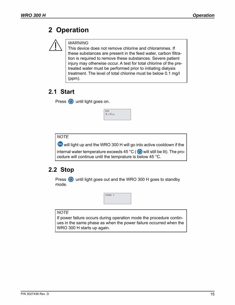
2 Operation
2.1 StartPress until light goes on.
2.2 Stop Press until light goes out and the WRO 300 H goes to standby mode.
WARNINGThis device does not remove chlorine and chloramines. If these substances are present in the feed water, carbon filtra-tion is required to remove these substances. Severe patient injury may otherwise occur. A test for total chlorine of the pre-treated water must be performed prior to initiating dialysis treatment. The level of total chlorine must be below 0.1 mg/l (ppm).
NOTE
will light up and the WRO 300 H will go into active cooldown if the internal water temperature exceeds 45 °C ( will still be lit). The pro-cedure will continue until the temprature is below 45 °C.
NOTEIf power failure occurs during operation mode the procedure contin-ues in the same phase as when the power failure occurred when the WRO 300 H starts up again.
RUN X μS/cm
STAND�Y
. D 15

Operation
16
WRO 300 H
This page is blank.
P/N 3027436 Rev. D
WRO 300 H
P/N 3027436 Rev
Regular Maintenance
3 Regular Maintenance
3.1 Heat DisinfectionThe required heat disinfection frequency to fulfil the desired microbio-logical requirements for the product water depends on several factors such as:
• the quality of the feed water
• local regulations regarding the microbiological quality of dialysis water, etc.
No general rules can be given that cover all situations. The disinfection schedule should be based upon microbiological testing performed by the clinic. A maximum period between disinfections should then be established to ensure acceptable bacteriological quality of the product water according to the clinic’s standards.
MCP recommends a minimum frequency of weekly heat disinfection to ensure consistent microbiological quality of the product water.
If the WRO 300 H will not be used for an extended period of time, reg-ular automated heat disinfection preset by the time channels will main-tain the microbiological quality of the product water.
3.1.1 Heat Disinfection ProcedureThe following paragraphs describe the heat disinfection of the WRO 300 H and the product water loop.
NOTEThe procedure below assume factory settings of the protocol.
NOTEIf the internal water temperature exceeds 45 °C when initiating the preferred procedure the display reverts to the SELECT menu or the CHEM SELECT menu.This situation is resolved by initiating RUN and letting the WRO 300 H operate and perform an active cooldown until the temperature is below 45 °C.
NOTEThe dialysis machine shall be turned off when the heat disinfection procedure is performed.
NOTEThe heat disinfection procedure can also be initiated by the time chan-nels. Further information of time channel settings refer to the Service Manual.
. D 17
Regular Maintenance
18
WRO 300 H
Step 1 Press until SELECT is shown in the display and starts to flash.
Step 2 From SELECT, press to enter the list of available proce-dures.
Step 3 Select HEAT by using the .
Step 4 Initiate the heat disinfection by pressing until the light goes on.
3.1.2 Stop Heat Disinfection Sequence• Press until light goes on to stop the heat disinfection proce-
dure. An active cooldown is initiated, then the WRO 300 H goes to standby.
• For more information about the settings of active cooldown, refer to the Service Manual.
3.2 Chemical Disinfection
For certain peracetic acid disinfectants the manufacturer recommends that the WRO 300 H should be cleaned with an acid cleaning agent in accordance with the cleaning instructions prior to chemical disinfection to preserve the RO membrane. Refer to the section, Cleaning on page 24.
The use of an ultrafilter on the dialysis machine will remove possible contaminants originating from the product water and may therefore be used as a method to extend the time between chemical disinfection of the WRO 300 H.
Contact MCP for suitable chemical disinfectant for the procedures.
NOTEIf power failure occurs during heat disinfection procedure 301 INSUFFICIENT HEAT is displayed when the WRO 300 H restarts. Press until the WRO 300 H either goes to standby or an active cooldown is initiated if it is preset.
NOTEChemical disinfection is not required for WRO 300 H units. Heat dis-infection is the preferred method to maintain bacterial control.
NOTEThe MINNCARE® disinfection option is disabled at the factory and can be re-enabled by referring to the Service Manual for instructions.
P/N 3027436 Rev. D
WRO 300 H
P/N 3027436 Rev
Regular Maintenance
3.2.1 Approved Chemical Disinfectants• MINNCARE® Cold Sterilant
Required amount: 50 ml of concentrated disinfectant
3.2.2 Test Kit Example • Minncare Residual Test Strips, MCP order number 185-40-004
(preferred).
• STERICHEK® Residual Peroxide, MCP order number WT811905 (alternate).
3.2.3 Chemical Disinfection ProcedureChemical disinfection of the WRO, including product water loop.
Step 1 Place the WRO into standby mode.
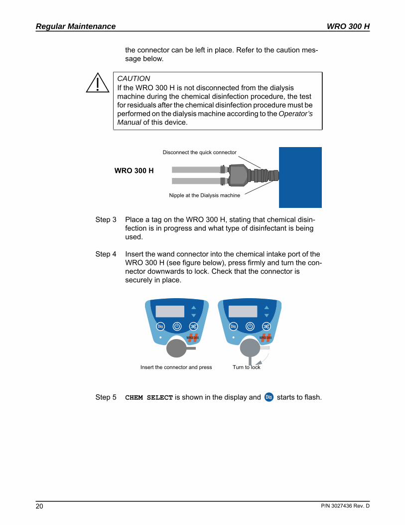
Step 2 Disconnect the WRO 300 H from the dialysis machine with the quick connector on the product water loop. Alternatively,
CAUTIONDisinfectants may be toxic. Refer to the manufacturer instruc-tions.
CAUTIONA test for residual disinfectant after rinse must be performed before the initiation of the next dialysis session. The residual concentration of the disinfectant in the fluid must be below lev-els specified by the clinic or by national standards. It is essen-tial to use an appropriate test method, either with proven sensitivity for the disinfectant or recommended by the manu-facturer of the disinfectant.
CAUTIONThe chemical container must be located below the chemical intake.
CAUTIONWhen requested by the WRO unit, remove the disinfection wand from the chemical intake. Failure to remove the disinfection wand can cause siphoning of the chemical solution from the bot-tle resulting in the tank overflowing chemical solution through the back of the machine.
NOTEIf power failure occurs during chemical disinfection 404 RINSE REQUIRED is displayed when the WRO 300 H restarts (also 401 REMOVE WAND is displayed during the intake phase). Press until light goes on, to initiate rinse.
. D 19
Regular Maintenance
20
WRO 300 H
the connector can be left in place. Refer to the caution mes-sage below.
Step 3 Place a tag on the WRO 300 H, stating that chemical disin-fection is in progress and what type of disinfectant is being used.
Step 4 Insert the wand connector into the chemical intake port of the WRO 300 H (see figure below), press firmly and turn the con-nector downwards to lock. Check that the connector is securely in place.
Step 5 CHEM SELECT is shown in the display and starts to flash.
CAUTIONIf the WRO 300 H is not disconnected from the dialysis machine during the chemical disinfection procedure, the test for residuals after the chemical disinfection procedure must be performed on the dialysis machine according to the Operator’s Manual of this device.
Disconnect the quick connector
Nipple at the Dialysis machine
WRO 300 H
Insert the connector and press Turn to lock
P/N 3027436 Rev. D
WRO 300 H
P/N 3027436 Rev
Regular Maintenance
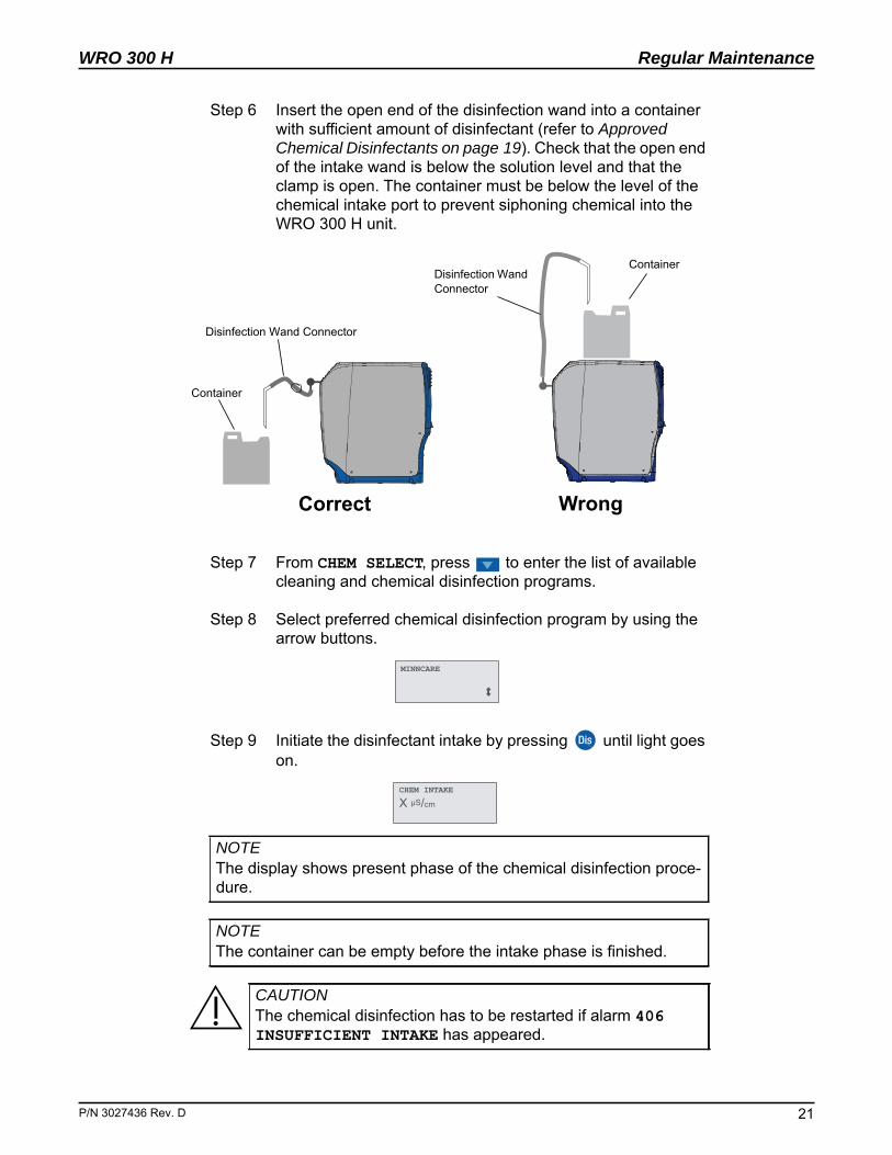
Step 6 Insert the open end of the disinfection wand into a container with sufficient amount of disinfectant (refer to Approved Chemical Disinfectants on page 19). Check that the open end of the intake wand is below the solution level and that the clamp is open. The container must be below the level of the chemical intake port to prevent siphoning chemical into the WRO 300 H unit.
Step 7 From CHEM SELECT, press to enter the list of available cleaning and chemical disinfection programs.
Step 8 Select preferred chemical disinfection program by using the arrow buttons.
Step 9 Initiate the disinfectant intake by pressing until light goes on.
NOTEThe display shows present phase of the chemical disinfection proce-dure.
NOTEThe container can be empty before the intake phase is finished.
CAUTIONThe chemical disinfection has to be restarted if alarm 406 INSUFFICIENT INTAKE has appeared.
ContainerDisinfection Wand Connector
Correct Wrong
Disinfection Wand Connector
Container
MINNCARE
CHEM INTAKE
X μS/cm
. D 21
Regular Maintenance
22
WRO 300 H
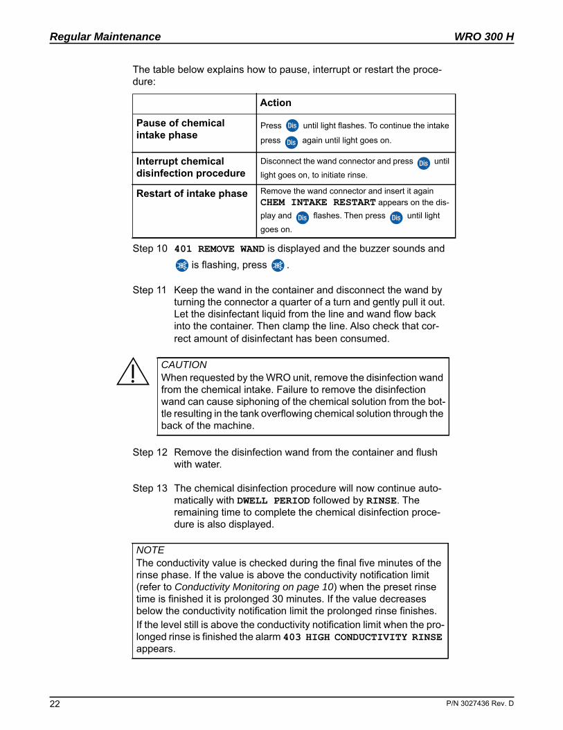
The table below explains how to pause, interrupt or restart the proce-dure:
Step 10 401 REMOVE WAND is displayed and the buzzer sounds and is flashing, press .
Step 11 Keep the wand in the container and disconnect the wand by turning the connector a quarter of a turn and gently pull it out. Let the disinfectant liquid from the line and wand flow back into the container. Then clamp the line. Also check that cor-rect amount of disinfectant has been consumed.
Step 12 Remove the disinfection wand from the container and flush with water.
Step 13 The chemical disinfection procedure will now continue auto-matically with DWELL PERIOD followed by RINSE. The remaining time to complete the chemical disinfection proce-dure is also displayed.
Action
Pause of chemical intake phase
Press until light flashes. To continue the intake
press again until light goes on.
Interrupt chemical disinfection procedure
Disconnect the wand connector and press until light goes on, to initiate rinse.
Restart of intake phase Remove the wand connector and insert it again CHEM INTAKE RESTART appears on the dis-play and flashes. Then press until light goes on.
CAUTIONWhen requested by the WRO unit, remove the disinfection wand from the chemical intake. Failure to remove the disinfection wand can cause siphoning of the chemical solution from the bot-tle resulting in the tank overflowing chemical solution through the back of the machine.
NOTEThe conductivity value is checked during the final five minutes of the rinse phase. If the value is above the conductivity notification limit (refer to Conductivity Monitoring on page 10) when the preset rinse time is finished it is prolonged 30 minutes. If the value decreases below the conductivity notification limit the prolonged rinse finishes.If the level still is above the conductivity notification limit when the pro-longed rinse is finished the alarm 403 HIGH CONDUCTIVITY RINSE appears.
P/N 3027436 Rev. D
WRO 300 H
P/N 3027436 Rev
Regular Maintenance
Step 14 When the chemical disinfection program is completed the dis-play will show PERFORM RESIDUAL TEST. The indication
will remain lighted and the will flash.
3.2.4 Residual Test After Chemical Disinfection
Step 1 Press until light goes on, to start WRO 300 H. Indication will light and will flash.
Step 2 Collect a water sample either from the product water line or from the dialysis machine according to the caution above.
Step 3 Test for disinfectant residuals with Minncare® Residual Per-oxide test strips or other approved test strips or methods.
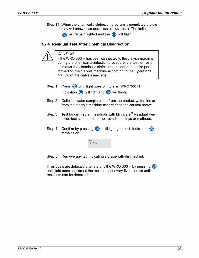
Step 4 Confirm by pressing until light goes out. Indication remains on.
Step 5 Remove any tag indicating storage with disinfectant.
If residuals are detected after starting the WRO 300 H by pressing until light goes on, repeat the residual test every five minutes until no residuals can be detected.
CAUTIONIf the WRO 300 H has been connected to the dialysis machine during the chemical disinfection procedure, the test for resid-uals after the chemical disinfection procedure must be per-formed on the dialysis machine according to the Operator’s Manual of the dialysis machine.
RUN X μS/cm
. D 23
Regular Maintenance
24
WRO 300 H
3.2.5 Central ChemThe central chem disinfects the WRO and also sends disinfectant into the dialysis machine. For more detailed information on how to perform central chem together with Gambro® dialysis machines, please contact Technical Service.
Follow the Chemical Disinfection Procedure on page 19, but start at Step 3 and follow the instruction through Step 13.
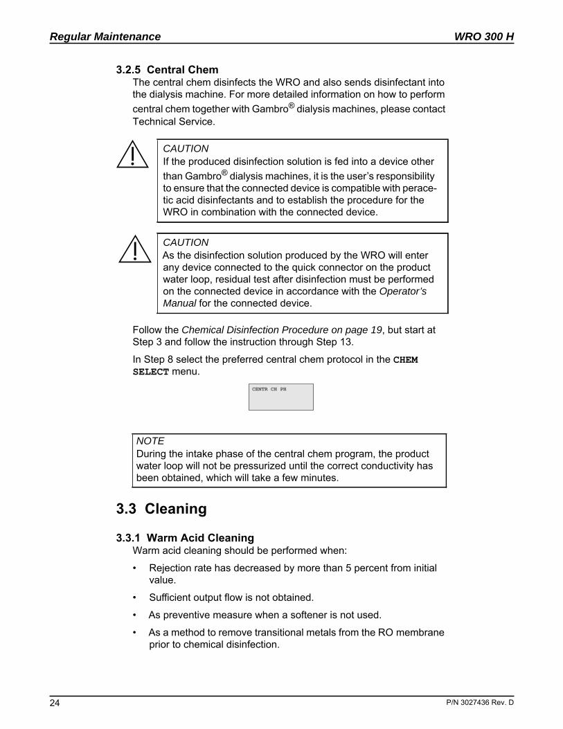
In Step 8 select the preferred central chem protocol in the CHEM SELECT menu.
3.3 Cleaning
3.3.1 Warm Acid CleaningWarm acid cleaning should be performed when:
• Rejection rate has decreased by more than 5 percent from initial value.
• Sufficient output flow is not obtained.
• As preventive measure when a softener is not used.
• As a method to remove transitional metals from the RO membrane prior to chemical disinfection.
CAUTIONIf the produced disinfection solution is fed into a device other than Gambro® dialysis machines, it is the user’s responsibility to ensure that the connected device is compatible with perace-tic acid disinfectants and to establish the procedure for the WRO in combination with the connected device.
CAUTIONAs the disinfection solution produced by the WRO will enter any device connected to the quick connector on the product water loop, residual test after disinfection must be performed on the connected device in accordance with the Operator’s Manual for the connected device.
NOTEDuring the intake phase of the central chem program, the product water loop will not be pressurized until the correct conductivity has been obtained, which will take a few minutes.
CENTR�CH�PH�
P/N 3027436 Rev. D
WRO 300 H
P/N 3027436 Rev
Regular Maintenance
Dissolve 100 ml of citric acid in 200 ml of product water from the WRO 300 H. This will result in a 2 percent solution in the WRO 300 H.
Refer to Cleaning Procedure below.
3.3.2 Alkaline CleaningAlkaline cleaning should be performed when:
• Product performance is affected and cleaning with citric acid does not improve performance.
• Organic fouling is suspected.
Use MINNCLEAN® TF according to manufacture’s instruction.
Refer to Cleaning Procedure below.
3.3.3 Cleaning ProcedureStep 1 Press until the display shows RUN. Wait until the product
water conductivity stabilizes and record the value. Press until light goes out to stop the WRO.
Step 2 Follow the chemical disinfection procedure, but instead select WARM CITRIC, or ALKALINE CLEAN in the CHEM SELECT menu. Refer to Chemical Disinfection Procedure on page 19.
3.3.4 Test for ResidualsStep 1 Press until light goes on, to start the WRO 300 H.
Indication will light and will flash.
Step 2 Collect a water sample from the product water line.
Step 3 The absence of cleaning chemical in the product water is confirmed if the pH is within 1.0 pH unit of the feed water value (checked with a suitable method) and if the conductivity of the product water corresponds to the previously recorded value.
NOTEOther acid membrane cleaners may be used as an alternative cleaner for the WRO 300 H. Follow the manufacturer’s guidelines to prepare the cleaning solution.
CAUTIONIf the temperature is not achieved during Warm Acid cleaning, alarm 407 INSUFFICIENT TEMPERATURE will appear and the cleaning procedure has to be restarted.
NOTEThe container can be empty before the intake phase is finished.
. D 25
Regular Maintenance
26
WRO 300 H
Step 4 Confirm by pressing until light goes out. Indication remains lighted.
3.4 Long Term StorageIf the WRO 300 H will not be used for an extended period of time, reg-ular automated heat disinfection preset by the time channels, will main-tain the microbiological quality in the WRO.
3.4.1 PreservationIf automated heat disinfection is not possible to perform when the WRO 300 H is taken out of operation for an extended period of time, a chemical preservation must be done. For example, perform preserva-tion if electrical and water connections are disconnected.
3.4.1.1 Preservation agentsUse MEMSTOR and dissolve 100 ml in two liters of potable tap water. Warm water (35-40°C) speeds up dissolution.
3.4.1.2 Preservation ProcedureStep 1 Follow the chemical disinfection procedure (refer to Chemical
Disinfection Procedure on page 19) Step 2 to Step 12, but instead select MEMSTOR in the CHEM SELECT menu.
Step 2 After Step 12: the display will show 404 RINSE REQUIRED and the buzzer will now sound and the indications and
will flash. Press , or acknowledge the alarm and the alarm list will be unlocked.
Step 3 Switch off the WRO 300 H with the mains power switch behind the detachable cover.
3.4.2 Rinse After PreservationStep 1 Turn on the WRO 300 H with the mains power switch behind
the detachable cover.
Step 2 The indication and flashes and the display shows 404 RINSE REQUIRED.
Step 3 Press until light goes on to initiate rinse.
CAUTIONIf the conductivity limit is not achieved, alarm 406 INSUFFI-CIENT INTAKE will appear and the preservation procedure has to be restarted.
RINSE
hh:mm
P/N 3027436 Rev. D
WRO 300 H
P/N 3027436 Rev
Regular Maintenance
Step 4 When the rinse program is completed the display will show PERFORM RESIDUAL TEST. The indication will remain lighted and the will flash.
3.4.3 Check for Complete Rinse-outThe required rinse program in the WRO has been designed and vali-dated to ensure complete rinse-out of the preservation.
Step 1 Press until light goes on, to start the WRO. Indication will light and will flash.
Step 2 Let the WRO run in normal operation for at least 5 minutes. Then press or to show the conductivity value in the display (within 15 seconds the display will return to PERFORM RESIDUAL TEST). Check and verify that the product water conductivity remains stable and constant.
Step 3 Confirm by pressing until light goes out. Indication remains lighted.
Step 4 The WRO is now ready to use.
3.5 Flush
3.5.1 Manual FlushThis mode provides a short flush of the WRO at elevated flow rate (5 minutes preset).
Step 1 Press until SELECT appears
Step 2 Scroll with to select MANUAL FLUSH.
Step 3 Press to initiate Manual Flush (MANUAL FLUSH will be displayed and will light).
3.5.2 Auto FlushDuring standby, auto flush is regularly performed to exchange water in the WRO, if enabled in preset. At specified intervals the water circu-lates in the WRO and some water goes to drain.
3.6 Exterior CleaningWipe the outside of the WRO 300 H with a cloth moistened with etha-nol (70 percent) or isopropanol (60 percent).
NOTEDo not use iodine-based or tenside-containing disinfectants as these may crack or discolor the plastic materials.
. D 27
WRO 300 H
P/N 3027436 Rev
Regular Maintenance
This page is blank.
. D 28
WRO 300 H
P/N 3027436 Rev
Technical Data
4 Technical Data
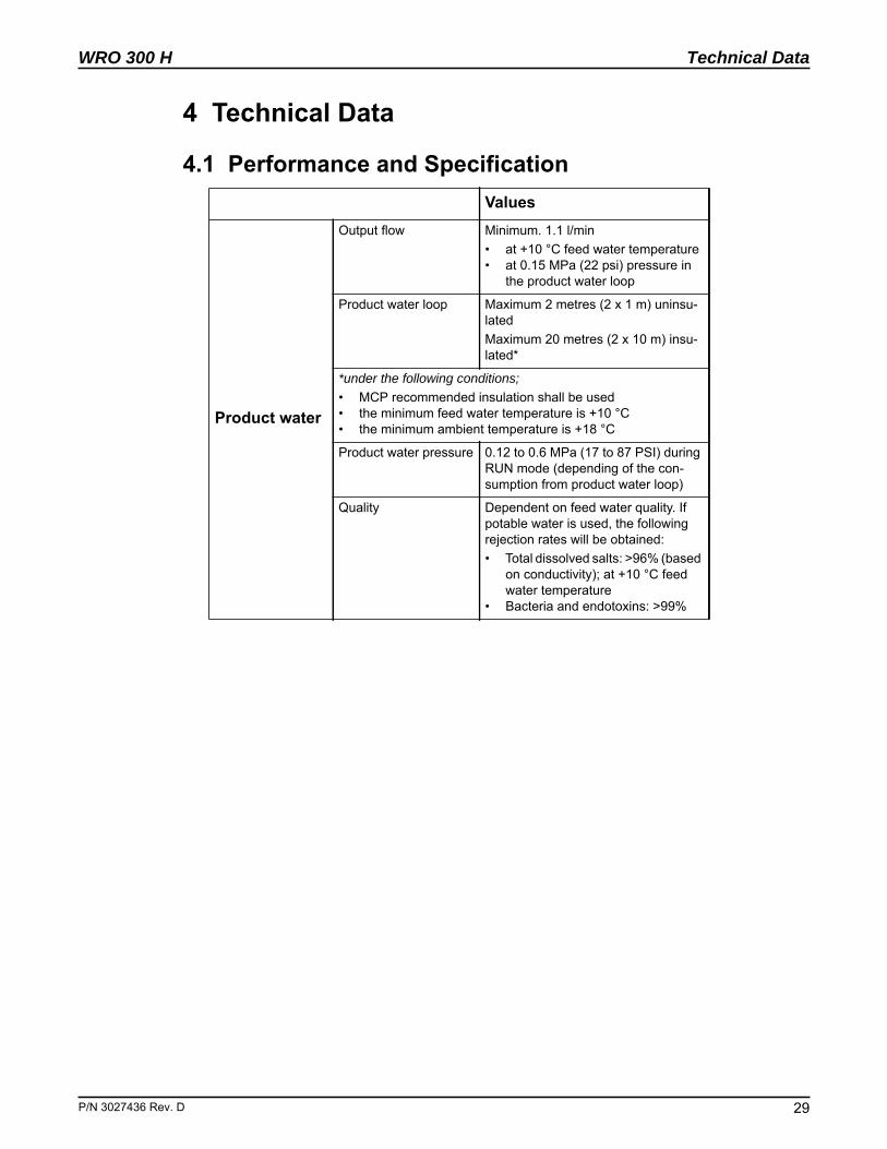
4.1 Performance and SpecificationValues
Product water
Output flow Minimum. 1.1 l/min • at +10 °C feed water temperature• at 0.15 MPa (22 psi) pressure in
the product water loop
Product water loop Maximum 2 metres (2 x 1 m) uninsu-latedMaximum 20 metres (2 x 10 m) insu-lated*
*under the following conditions;• MCP recommended insulation shall be used• the minimum feed water temperature is +10 °C• the minimum ambient temperature is +18 °C
Product water pressure 0.12 to 0.6 MPa (17 to 87 PSI) during RUN mode (depending of the con-sumption from product water loop)
Quality Dependent on feed water quality. If potable water is used, the following rejection rates will be obtained:• Total dissolved salts: >96% (based
on conductivity); at +10 °C feed water temperature
• Bacteria and endotoxins: >99%
. D 29
Technical Data
30
WRO 300 H
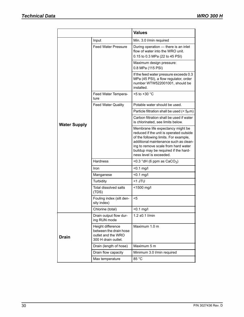
Water Supply
Input Min. 3.0 l/min required
Feed Water Pressure During operation — there is an inlet flow of water into the WRO unit.0.15 to 0.3 MPa (22 to 45 PSI)
Maximum design pressure:0.8 MPa (115 PSI)
If the feed water pressure exceeds 0.3 MPa (45 PSI), a flow regulator, order number WTW522001001, should be installed.
Feed Water Tempera-ture
+5 to +30 °C
Feed Water Quality Potable water should be used.
Particle filtration shall be used (< 5m)
Carbon filtration shall be used if water is chlorinated, see limits below.
Membrane life expectancy might be reduced if the unit is operated outside of the following limits. For example, additional maintenance such as clean-ing to remove scale from hard water buildup may be required if the hard-ness level is exceeded.
Hardness <0.3 °dH (6 ppm as CaCO3)
Iron <0.1 mg/l
Manganese <0.1 mg/l
Turbidity <1 JTU
Total dissolved salts (TDS)
<1500 mg/l
Fouling index (silt den-sity index)
<5
Chlorine (total) <0.1 mg/l
Drain
Drain output flow dur-ing RUN mode
1.2 ±0.1 l/min
Height difference between the drain hose outlet and the WRO 300 H drain outlet.
Maximum 1.0 m
Drain (length of hose) Maximum 5 m
Drain flow capacity Minimum 3.0 l/min required
Max temperature 85 °C
Values
P/N 3027436 Rev. D
WRO 300 H
P/N 3027436 Rev
Technical Data
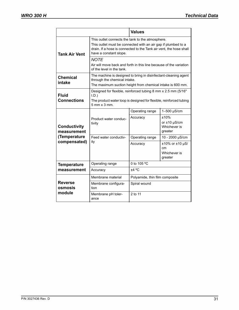
Tank Air Vent
This outlet connects the tank to the atmosphere.This outlet must be connected with an air gap if plumbed to a drain. If a hose is connected to the Tank air vent, the hose shall have a constant slope.
NOTEAir will move back and forth in this line because of the variation of the level in the tank.
Chemical intake
The machine is designed to bring in disinfectant-cleaning agent through the chemical intake.The maximum suction height from chemical intake is 600 mm.
Fluid Connections
Designed for flexible, reinforced tubing 8 mm x 2.5 mm (5/16" I.D.)The product water loop is designed for flexible, reinforced tubing 5 mm x 3 mm.
Conductivity measurement (Temperature compensated)
Product water conduc-tivity
Operating range 1–500 μS/cm
Accuracy ±10% or ±10 μS/cm Whichever is greater
Feed water conductiv-ity
Operating range 10 - 2000 μS/cm
Accuracy ±10% or ±10 μS/cmWhichever is greater
Temperature measurement
Operating range 0 to 105 ºC
Accuracy ±4 ºC
Reverse osmosis module
Membrane material Polyamide, thin film composite
Membrane configura-tion
Spiral wound
Membrane pH toler-ance
2 to 11
Values
. D 31
Technical Data
32
WRO 300 H
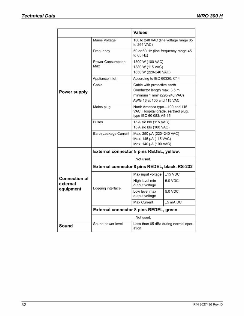
Power supply
Mains Voltage 100 to 240 VAC (line voltage range 85 to 264 VAC)
Frequency 50 or 60 Hz (line frequency range 45 to 65 Hz)
Power Consumption Max
1500 W (100 VAC)1380 W (115 VAC)1850 W (220-240 VAC)
Appliance inlet According to IEC 60320; C14
Cable Cable with protective earth Conductor length max. 3.5 mminimum 1 mm² (220-240 VAC)AWG 16 at 100 and 115 VAC
Mains plug North America type—100 and 115 VAC, Hospital grade, earthed plug, type IEC 60 083; A5-15
Fuses 15 A slo blo (115 VAC)15 A slo blo (100 VAC)
Earth Leakage Current Max. 250 μA (220–240 VAC)Max. 145 μA (115 VAC)Max. 140 μA (100 VAC)
Connection of external equipment
External connector 8 pins REDEL, yellow.Not used.
External connector 8 pins REDEL, black. RS-232
Logging interface
Max input voltage ±15 VDC
High level min output voltage
5.0 VDC
Low level max output voltage
5.0 VDC
Max Current ±5 mA DC
External connector 8 pins REDEL, green.Not used.
Sound Sound power level Less than 65 dBa during normal oper-ation
Values
P/N 3027436 Rev. D
WRO 300 H
P/N 3027436 Rev
Technical Data
4.2 Chemical Disinfection and Cleaning
4.3 Physical Data
Disinfection
The following disinfectants may be administered via the chemical intake.
• MINNCARE® Cold Sterilant • Other peracetic acid disinfectants, provided that they are
approved by the manufacturer for disinfection of thin film composite reverse osmosis membranes made of modified polyamide. Follow the manufacturer´s instructions for Use for the specific disinfectant.
Cleaning agents
The following cleaning agents may be administered via the chemical intake:
• Citric acid • Minnclean® AC• Minnclean® TF• Acetic Acid (5%)• Other cleaning agents may also be used, provided that they
are approved by the manufacturer for cleaning of thin film composite reverse osmosis membranes made of modified polyamide. Follow the manufacturer's instructions for use for the specific cleaning agent.
Preservation
The following preservations may be administered via the chemi-cal intake and feed water inlet:
• MEMSTOR ®• MEMSTOR ® in combination with 9 % glycerol• Formalin
Exterior cleaning
• Ethanol (70%) • Isopropanol (60%).
Measurements Values
Weight 33 kg (72.8 lb)
Height 563 mm (22.2 inch)
DepthMax 520 mm (20.5 inch)
Footprint 380 mm (15.0 inch)
WidthMax 205 mm (8.1 inch)
Footprint 185 mm (7.3 inch)
Internal fluid volume
Approximately 3.5 litres excluding the product water loop
. D 33
Technical Data
34
WRO 300 H
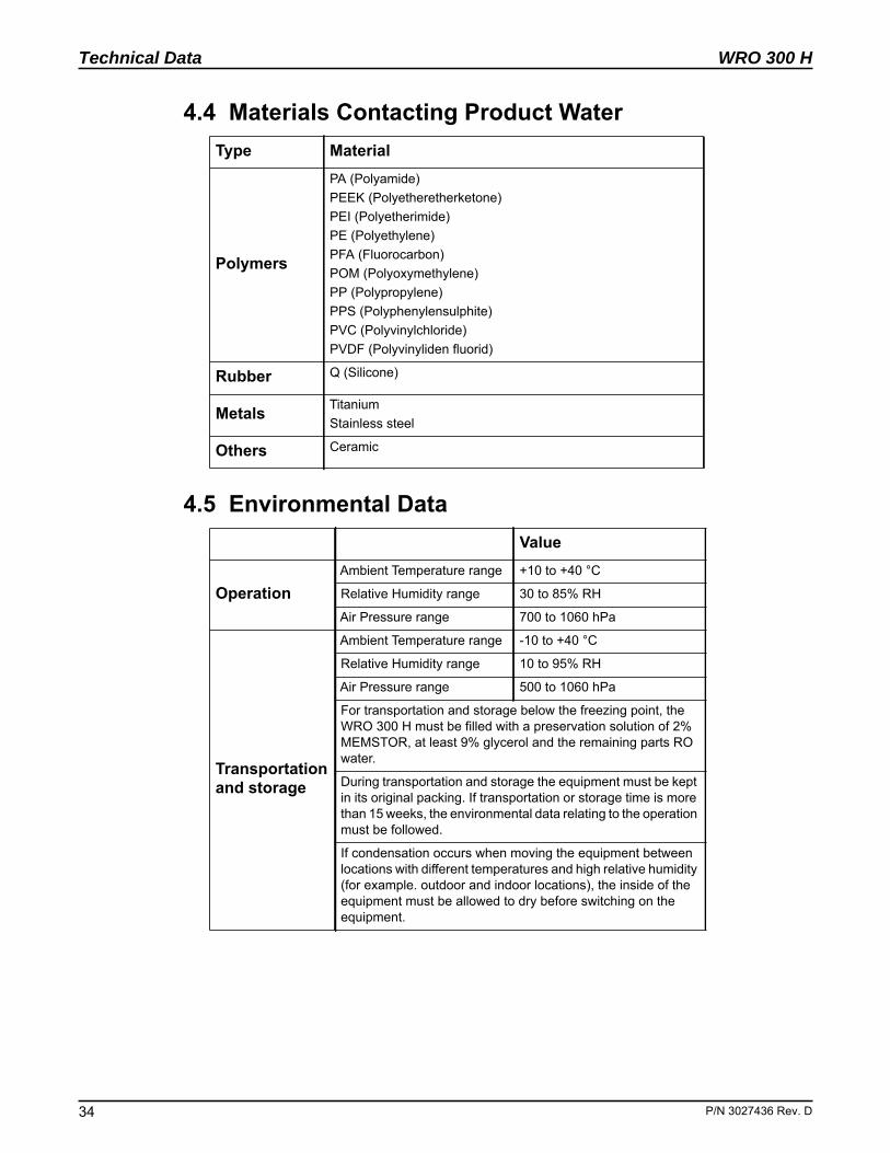
4.4 Materials Contacting Product Water
4.5 Environmental Data
Type Material
Polymers
PA (Polyamide)PEEK (Polyetheretherketone)PEI (Polyetherimide)PE (Polyethylene)PFA (Fluorocarbon)POM (Polyoxymethylene)PP (Polypropylene)PPS (Polyphenylensulphite)PVC (Polyvinylchloride)PVDF (Polyvinyliden fluorid)
Rubber Q (Silicone)
Metals TitaniumStainless steel
Others Ceramic
Value
OperationAmbient Temperature range +10 to +40 °C
Relative Humidity range 30 to 85% RH
Air Pressure range 700 to 1060 hPa
Transportation and storage
Ambient Temperature range -10 to +40 °C
Relative Humidity range 10 to 95% RH
Air Pressure range 500 to 1060 hPa
For transportation and storage below the freezing point, the WRO 300 H must be filled with a preservation solution of 2% MEMSTOR, at least 9% glycerol and the remaining parts RO water.
During transportation and storage the equipment must be kept in its original packing. If transportation or storage time is more than 15 weeks, the environmental data relating to the operation must be followed.
If condensation occurs when moving the equipment between locations with different temperatures and high relative humidity (for example. outdoor and indoor locations), the inside of the equipment must be allowed to dry before switching on the equipment.
P/N 3027436 Rev. D
WRO 300 H
P/N 3027436 Rev
Technical Data
. i-
al
y
e
d e
.
at al
at al
of -
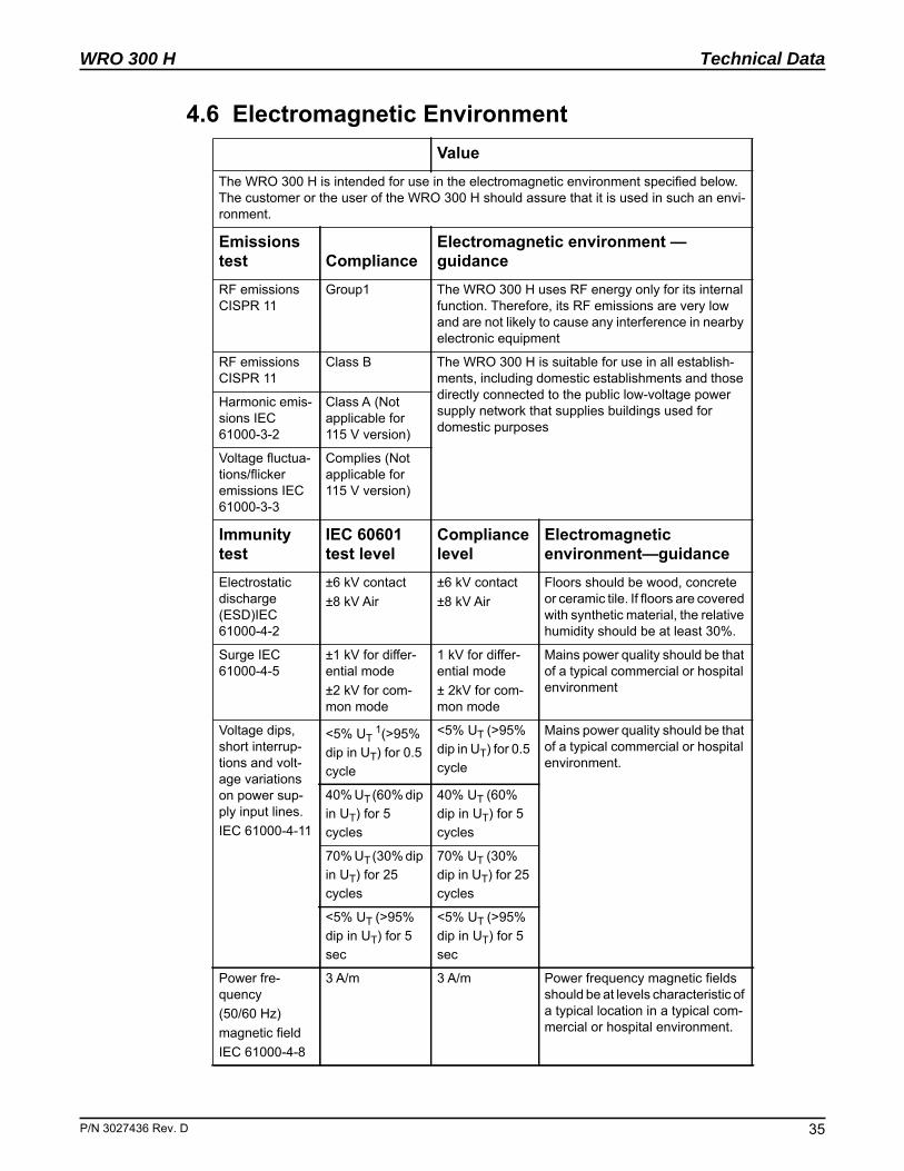
4.6 Electromagnetic EnvironmentValue
The WRO 300 H is intended for use in the electromagnetic environment specified belowThe customer or the user of the WRO 300 H should assure that it is used in such an envronment.
Emissions test Compliance
Electromagnetic environment — guidance
RF emissions CISPR 11
Group1 The WRO 300 H uses RF energy only for its internfunction. Therefore, its RF emissions are very low and are not likely to cause any interference in nearbelectronic equipment
RF emissions CISPR 11
Class B The WRO 300 H is suitable for use in all establish-ments, including domestic establishments and thosdirectly connected to the public low-voltage power supply network that supplies buildings used for domestic purposes
Harmonic emis-sions IEC 61000-3-2
Class A (Not applicable for 115 V version)
Voltage fluctua-tions/flicker emissions IEC 61000-3-3
Complies (Not applicable for 115 V version)
Immunity test
IEC 60601 test level
Compliance level
Electromagnetic environment—guidance
Electrostatic discharge (ESD)IEC 61000-4-2
±6 kV contact±8 kV Air
±6 kV contact±8 kV Air
Floors should be wood, concreteor ceramic tile. If floors are coverewith synthetic material, the relativhumidity should be at least 30%
Surge IEC 61000-4-5
±1 kV for differ-ential mode±2 kV for com-mon mode
1 kV for differ-ential mode± 2kV for com-mon mode
Mains power quality should be thof a typical commercial or hospitenvironment
Voltage dips, short interrup-tions and volt-age variations on power sup-ply input lines.IEC 61000-4-11
<5% UT 1(>95%
dip in UT) for 0.5 cycle
<5% UT (>95% dip in UT) for 0.5 cycle
Mains power quality should be thof a typical commercial or hospitenvironment.
40% UT (60% dip in UT) for 5 cycles
40% UT (60% dip in UT) for 5 cycles
70% UT (30% dip in UT) for 25 cycles
70% UT (30% dip in UT) for 25 cycles
<5% UT (>95% dip in UT) for 5 sec
<5% UT (>95% dip in UT) for 5 sec
Power fre-quency(50/60 Hz)magnetic fieldIEC 61000-4-8
3 A/m 3 A/m Power frequency magnetic fieldsshould be at levels characteristic a typical location in a typical commercial or hospital environment.
. D 35
Technical Data
36
WRO 300 H
2
i-d e li-s-
- e
n
n-
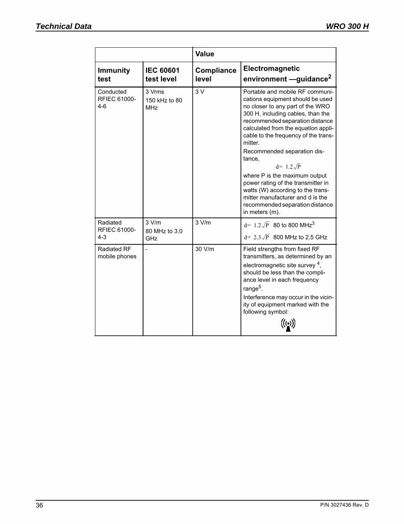
Immunity test
IEC 60601 test level
Compliance level
Electromagnetic environment —guidance
Conducted RFIEC 61000-4-6
3 Vrms150 kHz to 80 MHz
3 V Portable and mobile RF communcations equipment should be useno closer to any part of the WRO300 H, including cables, than therecommended separation distanccalculated from the equation appcable to the frequency of the tranmitter.Recommended separation dis-tance,
where P is the maximum output power rating of the transmitter inwatts (W) according to the transmitter manufacturer and d is therecommended separation distancin meters (m).
Radiated RFIEC 61000-4-3
3 V/m80 MHz to 3.0 GHz
3 V/m 80 to 800 MHz3
800 MHz to 2.5 GHz
Radiated RF mobile phones
- 30 V/m Field strengths from fixed RF transmitters, as determined by aelectromagnetic site survey 4, should be less than the compli-ance level in each frequency range5.Interference may occur in the viciity of equipment marked with thefollowing symbol:
Value
d 1.2 P=
d 1.2 P =
d 2.3 P =
P/N 3027436 Rev. D
WRO 300 H
P/N 3027436 Rev
Technical Data
d e- -t.
p-e-in
Recommended separation distances between portable and mobile RF communications equipment and the WRO 300 HThe WRO 300 H is intended for use in an electromagnetic environment in which radiateRF disturbances are controlled. The customer or the user of the WRO 300 H can help prvent electromagnetic interference by maintaining a minimum distance between portableand mobile RF communications equipment (transmitters) and the WRO 300 H as recommended below, according to the maximum output power of the communications equipmen
Rated maximum output power of transmitterW
Separation distance according to frequency of transmitter (m)150 kHz to 80 MHz
80 MHz to800 MHz 6
800 MHz to 3 GHz
0,01 0.11 0.11 0.23
0,1 0.37 0.37 0.74
1 1.2 1.2 2.3
10 3.7 3.7 7.4
100 12 12 23
Rated maxi-mum output power of mobile phone
- -
2W GSM/3G - - 0.33
For transmitters rated at a maximum output power not listed above, the recommended searation distance d in meters (m) can be estimated using the equation applicable to the frquency of the transmitter, where P is the maximum output power rating of the transmitter watts (W) according to the transmitter manufacturer.
1. NOTE: UT is the AC mains voltage prior to application of the test level.2. NOTE: These guidelines may not apply in all situations. Electromagnetic propa-
gation is affected by absorption and reflection from structures, objects and peo-ple.
3. NOTE: At 80 MHz and 800 MHz, the higher frequency range applies.4. Field strengths from fixed transmitters, such as base stations for radio (cellular/
cordless) telephones and land mobile radios, amateur radio, AM and FM radio broadcast and TV broadcast cannot be predicted theoretically with accuracy. To assess the electromagnetic environment due to fixed RF transmitters, an elec-tromagnetic site survey should be considered. If the measured field strength in the location in which the WRO 300 H is used exceeds the applicable RF compli-ance level above, the WRO 300 H should be observed to verify normal opera-tion. If abnormal performance is observed, additional measures may be necessary, such as reorienting or relocating the WRO 300 H.
5. Over the frequency range 150 kHz to 80 MHz, field strengths should be less than 3 V/m.
6. NOTE: At 80 MHz and 800 MHz, the separation distance for the higher fre-quency range applies.
Value
d 3.53
------- P= d 3.53
------- P= d 73--- P=
d 730------ P=
. D 37
Technical Data
38
WRO 300 H
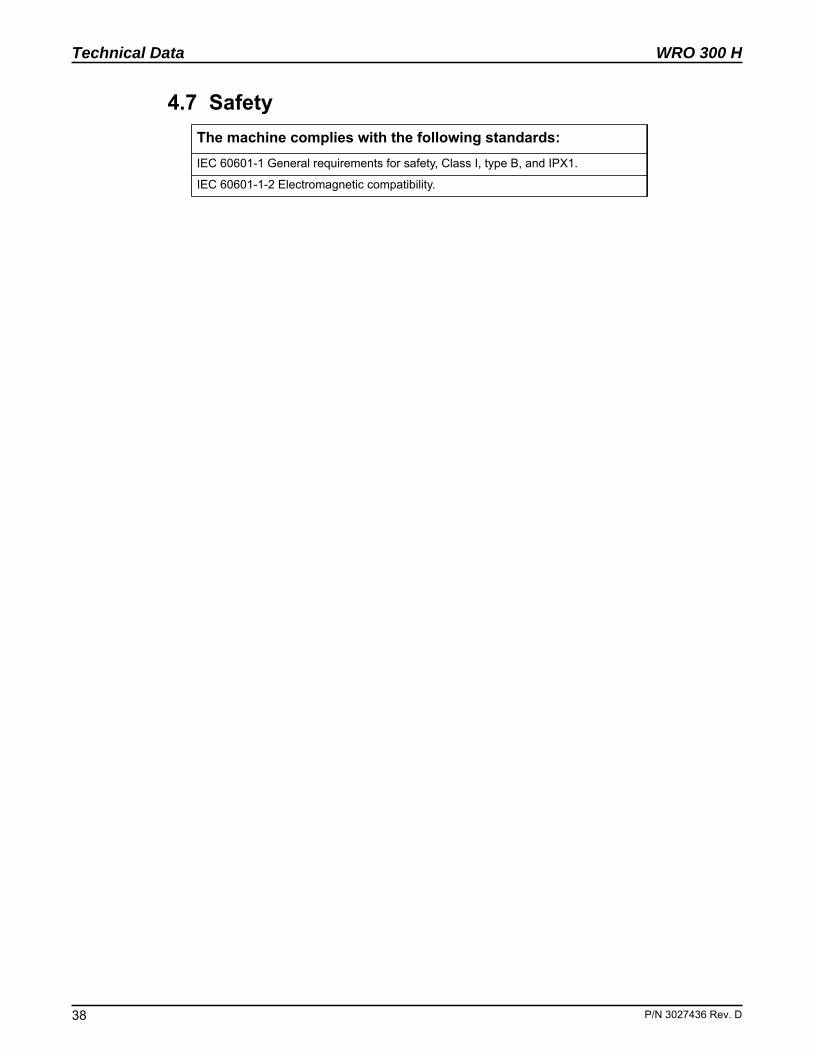
4.7 SafetyThe machine complies with the following standards:IEC 60601-1 General requirements for safety, Class I, type B, and IPX1.
IEC 60601-1-2 Electromagnetic compatibility.
P/N 3027436 Rev. D
WRO 300 H
P/N 3027436 Rev
Troubleshooting
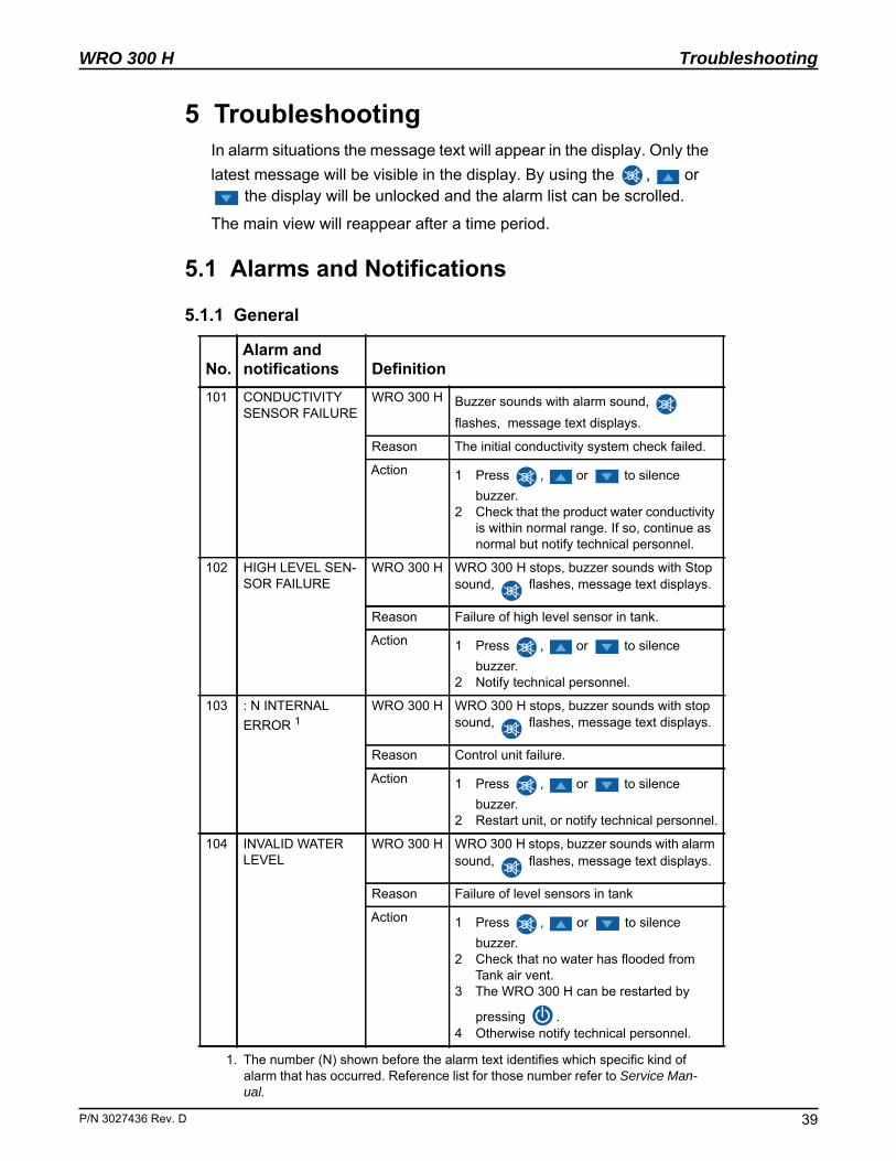
5 TroubleshootingIn alarm situations the message text will appear in the display. Only the latest message will be visible in the display. By using the , or
the display will be unlocked and the alarm list can be scrolled.
The main view will reappear after a time period.
5.1 Alarms and Notifications
5.1.1 General
No.Alarm andnotifications Definition
101 CONDUCTIVITY SENSOR FAILURE
WRO 300 H Buzzer sounds with alarm sound, flashes, message text displays.
Reason The initial conductivity system check failed.
Action 1 Press , or to silence buzzer.
2 Check that the product water conductivity is within normal range. If so, continue as normal but notify technical personnel.
102 HIGH LEVEL SEN-SOR FAILURE
WRO 300 H WRO 300 H stops, buzzer sounds with Stop sound, flashes, message text displays.
Reason Failure of high level sensor in tank.
Action 1 Press , or to silence buzzer.
2 Notify technical personnel.
103 : N INTERNAL ERROR 1
1. The number (N) shown before the alarm text identifies which specific kind of alarm that has occurred. Reference list for those number refer to Service Man-ual.
WRO 300 H WRO 300 H stops, buzzer sounds with stop sound, flashes, message text displays.
Reason Control unit failure.
Action 1 Press , or to silence buzzer.
2 Restart unit, or notify technical personnel.
104 INVALID WATER LEVEL
WRO 300 H WRO 300 H stops, buzzer sounds with alarm sound, flashes, message text displays.
Reason Failure of level sensors in tank
Action 1 Press , or to silence buzzer.
2 Check that no water has flooded from Tank air vent.
3 The WRO 300 H can be restarted by
pressing .4 Otherwise notify technical personnel.
. D 39
Troubleshooting
40
WRO 300 H
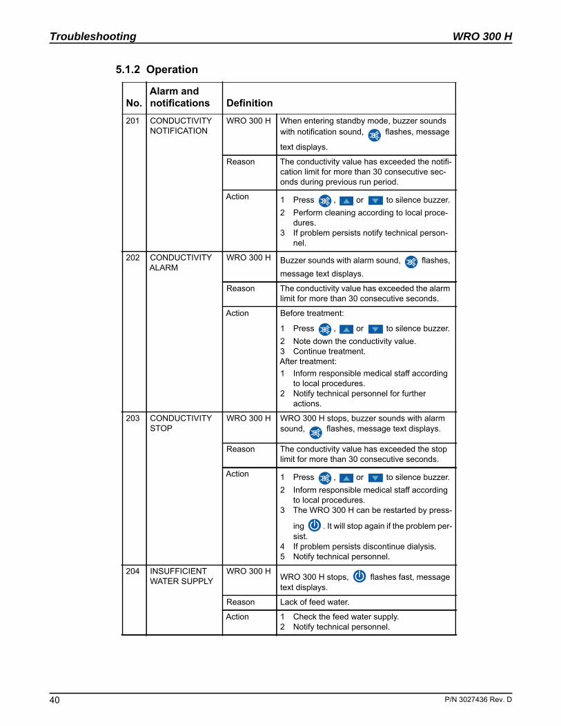
5.1.2 Operation
No.Alarm andnotifications Definition
201 CONDUCTIVITY NOTIFICATION
WRO 300 H When entering standby mode, buzzer sounds with notification sound, flashes, message
text displays.
Reason The conductivity value has exceeded the notifi-cation limit for more than 30 consecutive sec-onds during previous run period.
Action 1 Press , or to silence buzzer.2 Perform cleaning according to local proce-
dures.3 If problem persists notify technical person-
nel.
202 CONDUCTIVITY ALARM
WRO 300 H Buzzer sounds with alarm sound, flashes, message text displays.
Reason The conductivity value has exceeded the alarm limit for more than 30 consecutive seconds.
Action Before treatment:
1 Press , or to silence buzzer. 2 Note down the conductivity value.3 Continue treatment.After treatment:1 Inform responsible medical staff according
to local procedures.2 Notify technical personnel for further
actions.
203 CONDUCTIVITY STOP
WRO 300 H WRO 300 H stops, buzzer sounds with alarm sound, flashes, message text displays.
Reason The conductivity value has exceeded the stop limit for more than 30 consecutive seconds.
Action 1 Press , or to silence buzzer. 2 Inform responsible medical staff according
to local procedures.3 The WRO 300 H can be restarted by press-
ing . It will stop again if the problem per-sist.
4 If problem persists discontinue dialysis.5 Notify technical personnel.
204 INSUFFICIENT WATER SUPPLY
WRO 300 HWRO 300 H stops, flashes fast, message text displays.
Reason Lack of feed water.
Action 1 Check the feed water supply.2 Notify technical personnel.
P/N 3027436 Rev. D
WRO 300 H
P/N 3027436 Rev
Troubleshooting
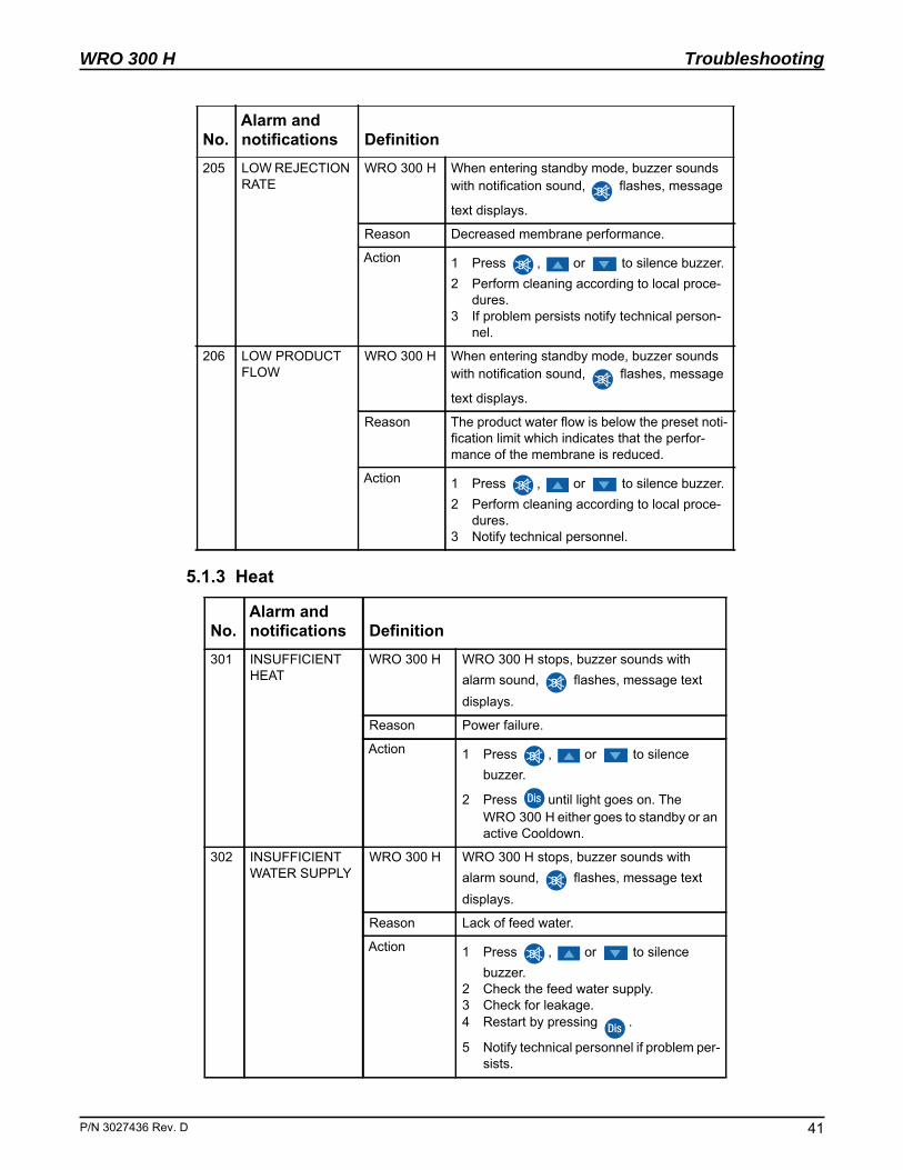
5.1.3 Heat
205 LOW REJECTION RATE
WRO 300 H When entering standby mode, buzzer sounds with notification sound, flashes, message
text displays.
Reason Decreased membrane performance.
Action 1 Press , or to silence buzzer. 2 Perform cleaning according to local proce-
dures.3 If problem persists notify technical person-
nel.
206 LOW PRODUCT FLOW
WRO 300 H When entering standby mode, buzzer sounds with notification sound, flashes, message
text displays.
Reason The product water flow is below the preset noti-fication limit which indicates that the perfor-mance of the membrane is reduced.
Action 1 Press , or to silence buzzer. 2 Perform cleaning according to local proce-
dures.3 Notify technical personnel.
No.Alarm andnotifications Definition
301 INSUFFICIENT HEAT
WRO 300 H WRO 300 H stops, buzzer sounds with alarm sound, flashes, message text displays.
Reason Power failure.
Action 1 Press , or to silence buzzer.
2 Press until light goes on. The WRO 300 H either goes to standby or an active Cooldown.
302 INSUFFICIENT WATER SUPPLY
WRO 300 H WRO 300 H stops, buzzer sounds with alarm sound, flashes, message text displays.
Reason Lack of feed water.
Action 1 Press , or to silence buzzer.
2 Check the feed water supply.3 Check for leakage.4 Restart by pressing .
5 Notify technical personnel if problem per-sists.
No.Alarm andnotifications Definition
. D 41
Troubleshooting
42
WRO 300 H
5.1.4 Chemical, Cleaning, Rinse and Preservation
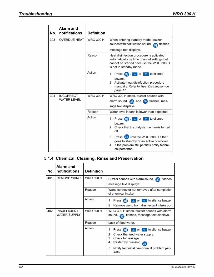
303 OVERDUE HEAT WRO 300 H When entering standby mode, buzzer sounds with notification sound, flashes,
message text displays.
Reason Heat disinfection procedure is activated automatically by time channel settings but cannot be started because the WRO 300 H is not in standby mode.
Action 1 Press , or to silence buzzer.
2 Activate heat disinfection procedure manually. Refer to Heat Disinfection on page 17.
304 INCORRECT WATER LEVEL
WRO 300 H WRO 300 H stops, buzzer sounds with alarm sound, and flashes, mes-sage text displays.
Reason Water level in tank is lower than expected.
Action 1 Press , or to silence buzzer.
2 Check that the dialysis machine is turned off.
3 Press until the WRO 300 H either goes to standby or an active cooldown.
4 If the problem still persists notify techni-cal personnel.
No.Alarm andnotifications Definition
401 REMOVE WAND WRO 300 H Buzzer sounds with alarm sound, flashes, message text displays.
Reason Wand connector not removed after completion of chemical intake.
Action 1 Press , or to silence buzzer. 2 Remove wand from disinfectant intake port.
402 INSUFFICIENT WATER SUPPLY
WRO 300 H WRO 300 H stops, buzzer sounds with alarm sound, flashes, message text displays.
Reason Lack of feed water.
Action 1 Press , or to silence buzzer. 2 Check the feed water supply.3 Check for leakage.4 Restart by pressing .
5 Notify technical personnel if problem per-sists.
No.Alarm andnotifications Definition
P/N 3027436 Rev. D
WRO 300 H
P/N 3027436 Rev
Troubleshooting
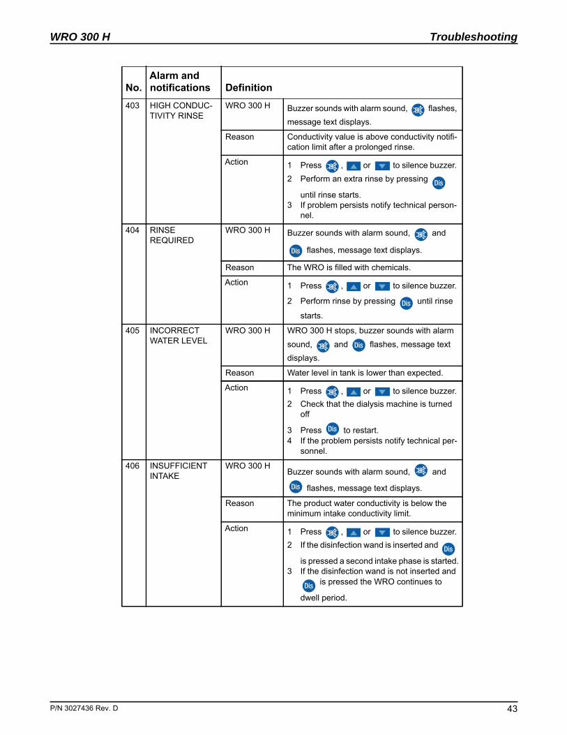
403 HIGH CONDUC-TIVITY RINSE
WRO 300 H Buzzer sounds with alarm sound, flashes, message text displays.
Reason Conductivity value is above conductivity notifi-cation limit after a prolonged rinse.
Action 1 Press , or to silence buzzer. 2 Perform an extra rinse by pressing
until rinse starts. 3 If problem persists notify technical person-
nel.
404 RINSE REQUIRED
WRO 300 H Buzzer sounds with alarm sound, and
flashes, message text displays.
Reason The WRO is filled with chemicals.
Action 1 Press , or to silence buzzer.
2 Perform rinse by pressing until rinse
starts.
405 INCORRECT WATER LEVEL
WRO 300 H WRO 300 H stops, buzzer sounds with alarm sound, and flashes, message text displays.
Reason Water level in tank is lower than expected.
Action 1 Press , or to silence buzzer. 2 Check that the dialysis machine is turned
off
3 Press to restart.4 If the problem persists notify technical per-
sonnel.
406 INSUFFICIENT INTAKE
WRO 300 HBuzzer sounds with alarm sound, and
flashes, message text displays.
Reason The product water conductivity is below the minimum intake conductivity limit.
Action 1 Press , or to silence buzzer. 2 If the disinfection wand is inserted and
is pressed a second intake phase is started.3 If the disinfection wand is not inserted and
is pressed the WRO continues to
dwell period.
No.Alarm andnotifications Definition
. D 43
Troubleshooting
44
WRO 300 H
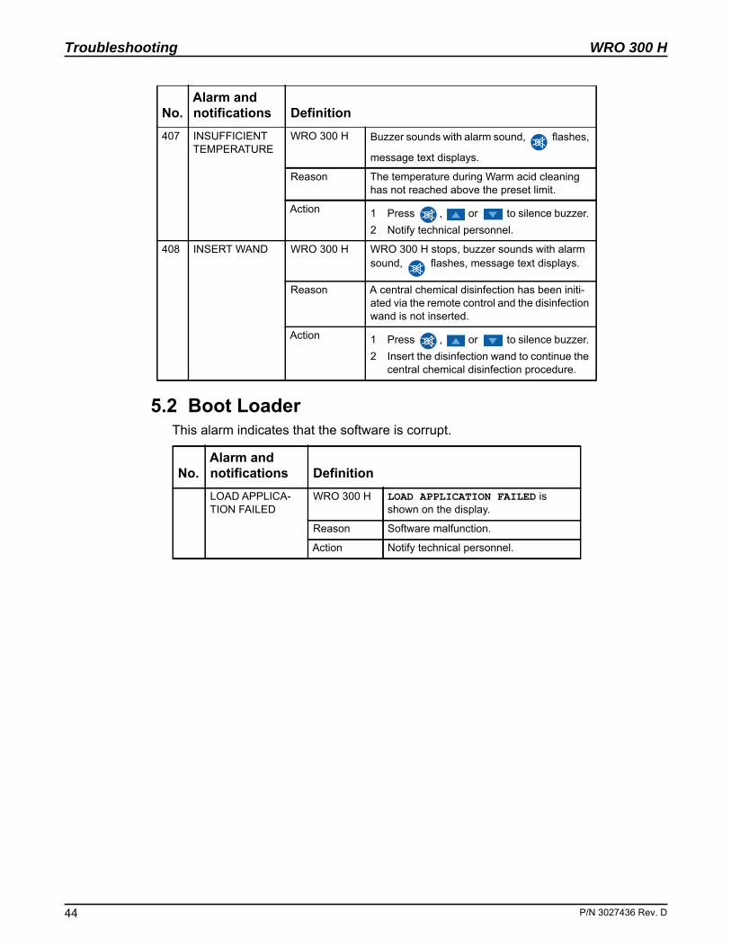
5.2 Boot LoaderThis alarm indicates that the software is corrupt.
407 INSUFFICIENT TEMPERATURE
WRO 300 H Buzzer sounds with alarm sound, flashes,
message text displays.
Reason The temperature during Warm acid cleaning has not reached above the preset limit.
Action 1 Press , or to silence buzzer. 2 Notify technical personnel.
408 INSERT WAND WRO 300 H WRO 300 H stops, buzzer sounds with alarm sound, flashes, message text displays.
Reason A central chemical disinfection has been initi-ated via the remote control and the disinfection wand is not inserted.
Action 1 Press , or to silence buzzer. 2 Insert the disinfection wand to continue the
central chemical disinfection procedure.
No.Alarm andnotifications Definition LOAD APPLICA-TION FAILED
WRO 300 H LOAD APPLICATION FAILED is shown on the display.
Reason Software malfunction.
Action Notify technical personnel.
No.Alarm andnotifications Definition
P/N 3027436 Rev. D
WRO 300 H
P/N 3027436 Rev
Check List
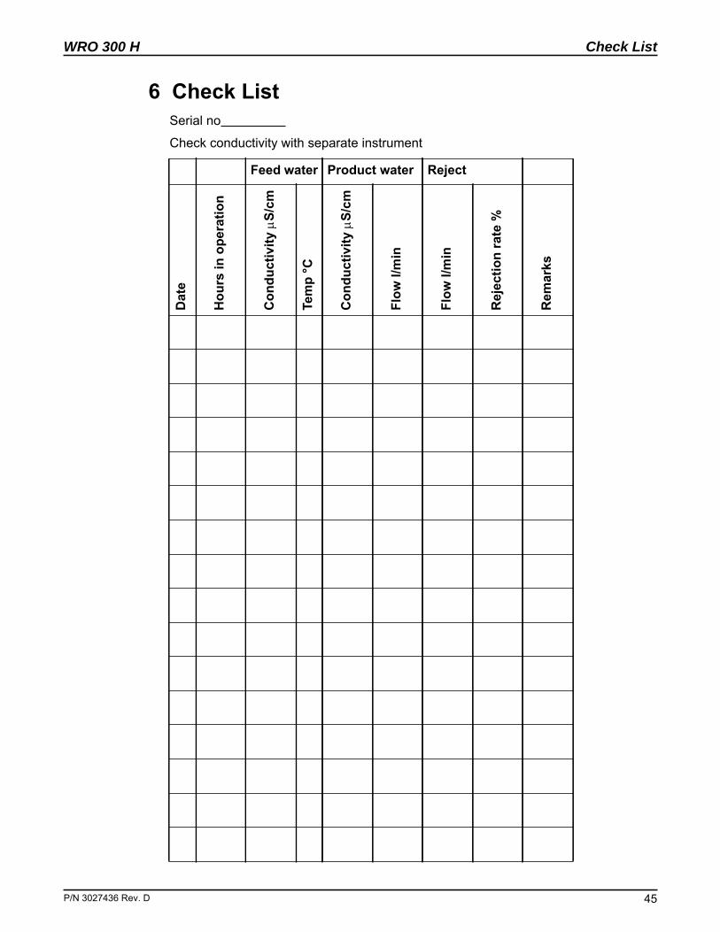
6 Check ListSerial no
Check conductivity with separate instrument
Feed water Product water RejectD
ate
Hou
rs in
ope
ratio
n
Con
duct
ivity
S/
cm
Tem
p °C
Con
duct
ivity
S/
cm
Flow
l/m
in
Flow
l/m
in
Rej
ectio
n ra
te %
Rem
arks
. D 45

Check List
46
WRO 300 H
This page is blank.
P/N 3027436 Rev. D
WRO 300 H
P/N 3027436 Rev
Index
Index
AAcid cleaning . . . . . . . . . . . . . . . . . . . . 24Alarm Types
Alarm . . . . . . . . . . . . . . . . . . . . . . . 10Info . . . . . . . . . . . . . . . . . . . . . . . . . 10Notification . . . . . . . . . . . . . . . . . . . 10Stop . . . . . . . . . . . . . . . . . . . . . . . . 10
Alarm types . . . . . . . . . . . . . . . . . . . . . 10Alarms and notifications . . . . . . . . . . . . 39
Chemical . . . . . . . . . . . . . . . . . . . . 42General . . . . . . . . . . . . . . . . . . . . . 39Heat . . . . . . . . . . . . . . . . . . . . . . . . 41Operation . . . . . . . . . . . . . . . . . . . . 40Preservation . . . . . . . . . . . . . . . . . . 42Rinse . . . . . . . . . . . . . . . . . . . . . . . 42
Alkaline cleaning . . . . . . . . . . . . . . . . . 25Auto flush . . . . . . . . . . . . . . . . . . . . . 9, 27
BBoot loader . . . . . . . . . . . . . . . . . . . . . . 44Buttons . . . . . . . . . . . . . . . . . . . . . . . . . 12
CCentral Chem . . . . . . . . . . . . . . . . . . . . 24Check list . . . . . . . . . . . . . . . . . . . . . . . 45Chemical disinfection
Central Chem . . . . . . . . . . . . . . . . . 24Cleaning . . . . . . . . . . . . . . . . . . . . . 24, 42
Acid . . . . . . . . . . . . . . . . . . . . . . . . 24Alkaline . . . . . . . . . . . . . . . . . . . . . . 25
Complete rinse-out . . . . . . . . . . . . . . . . 27Conductivity
Alarm . . . . . . . . . . . . . . . . . . . . . . . 11Monitoring . . . . . . . . . . . . . . . . . . . 10Notification . . . . . . . . . . . . . . . . . . . 10Stop . . . . . . . . . . . . . . . . . . . . . . . . 11
EExterior cleaning . . . . . . . . . . . . . . . . . 27
FFlash indications . . . . . . . . . . . . . . . . . 13
IIndications . . . . . . . . . . . . . . . . . . . . . . 13Intended use . . . . . . . . . . . . . . . . . . . . . 9Interrupt . . . . . . . . . . . . . . . . . . . . . . . . 22
LLong time Storage . . . . . . . . . . . . . . . . 26Low rejection rate
Notification . . . . . . . . . . . . . . . . . . . 11
MMains power switch . . . . . . . . . . . . . . . 12Maintenance . . . . . . . . . . . . . . . . . . . . . 17
Chemical disinfectants . . . . . . . . . . 19Chemical disinfection . . . . . . . . . . . 18Heat Disinfection . . . . . . . . . . . . . . . 17
Manual Flush . . . . . . . . . . . . . . . . . . . . 27
OOperation . . . . . . . . . . . . . . . . . . . . . . . 15
Start . . . . . . . . . . . . . . . . . . . . . . . . 15Stop . . . . . . . . . . . . . . . . . . . . . . . . 15
Operational data . . . . . . . . . . . . . . . . . . 14Operator’s panel . . . . . . . . . . . . . . . . . . 12
PPreservation . . . . . . . . . . . . . . . . . . . . . 26Preservation Procedure . . . . . . . . . . . . 26
RReminders . . . . . . . . . . . . . . . . . . . . . . 14Residual test
Chemical disinfection . . . . . . . . . . . 23Cleaning . . . . . . . . . . . . . . . . . . . . . 25
Restart . . . . . . . . . . . . . . . . . . . . . . . . . 22Rinse
Preservation . . . . . . . . . . . . . . . . . . 26
TTechnical data . . . . . . . . . . . . . . . . . . . 29
Chemical disinfection and Cleaning 33Environmental data . . . . . . . . . . . . . 34Performance and specification . . . . 29Physical data . . . . . . . . . . . . . . . . . 33Safety . . . . . . . . . . . . . . . . . . . . . . . 38
Troubleshooting . . . . . . . . . . . . . . . . . . 39
WWarm Acid cleaning . . . . . . . . . . . . . . . 24
. D 47

Index
48
WRO 300 H
This page is blank.
P/N 3027436 Rev. D


Mar Cor Purification4450 Township Line RoadSkippack, PA 19474-1429Tel: (484) 991-0220Toll Free: (800) 633-3080Fax: (484) 991-0230
Mar Cor Purification14550 28th Avenue NorthPlymouth, MN 55447Tel: (484) 991-0220 Toll Free: (800) 633-3080Fax: (763) 210-3868
Mar Cor Purification1119 Paulsun StreetSan Antonio, TX 78219Tel: (210) 227-3601Toll Free: (800) 268-5035Fax: (210) 227-0735
Mar Cor Purification160 Stedman StreetLowell, MA 01851Tel: (978) 453-9600 Toll Free: (800) 633-3080Fax: (978) 453-1223
Mar Cor Purification 6351 Orangethorpe Ave.Buena Park, CA 90620Tel: (714) 736-9990 Toll Free: (800) 633-3080Fax: (714) 736-9402
Visit http://www.mcpur.com or call 1-800-633-3080 for more information.
©2016 Mar Cor Purification, Inc.All rights reservedP/N 3027436 Rev. D


![Octavian Cira and Florentin Smarandache - arXiv · Octavian Cira and Florentin Smarandache arXiv:1603.08456v1 [math.GM] 28 Mar 2016 March 29, 2016. 2. Preface Over 300 sequences and](https://img.pdfslide.us/doc/110x75/5e2bdc56635537123a65b205/octavian-cira-and-florentin-smarandache-arxiv-octavian-cira-and-florentin-smarandache.jpg)