Embed Size (px)
Citation preview
MANUALE STAZIONE DI SERVIZIO638540
Stalker 50

MANUALESTAZIONE DI
SERVIZIO
Stalker 50
The descriptions and illustrations given in this publication are not binding. While the basic specificationsas described and illustrated in this manual remain unchanged, PIAGGIO-GILERA reserves the right, at
any time and without being required to update this publication beforehand, to make any changes tocomponents, parts or accessories, which it considers necessary to improve the product or which are
required for manufacturing or construction reasons.Not all versions/models shown in this publication are available in all countries. The availability of single
versions should be checked at the official Piaggio sales network."© Copyright 2007 - PIAGGIO & C. S.p.A. Pontedera. All rights reserved. Reproduction of this publication
in whole or in part is prohibited."PIAGGIO & C. S.p.A. - After-Sales
V.le Rinaldo Piaggio, 23 - 56025 PONTEDERA (Pi)

MANUALE STAZIONE DISERVIZIOStalker 50
Questo manuale per stazioni di servizio è stato realizzato da Piaggio & C. Spa per essere utilizzatodalle officine dei concessionari e sub-agenzie Piaggio-Gilera. Si presuppone che chi utilizza questapubblicazione per la manutenzione e la riparazione dei veicoli Piaggio, abbia una conoscenza base deiprincipi della meccanica e dei procedimenti inerenti la tecnica della riparazione dei veicoli. Le variazioniimportanti nelle caratteristiche dei veicoli o nelle specifiche operazioni di riparazione verrannocomunicate attraverso aggiornamenti di questo manuale. Non si può comunque realizzare un lavorocompletamente soddisfacente se non si dispone degli impianti e delle attrezzature necessarie, ed è perquesto che vi invitiamo a consultare le pagine di questo manuale riguardanti l'attrezzatura specifica eil catalogo degli attrezzi specifici.
N.B. Provides key information to make the procedure easier to understand and carry out.
CAUTION Refers to specific procedures to carry out for preventing damages to the vehicle.
WARNING Refers to specific procedures to carry out to prevent injuries to the repairer.
Personal safety Failure to completely observe these instructions will result in serious risk of personalinjury.
Safeguarding the environment Sections marked with this symbol indicate the correct use of the vehicleto prevent damaging the environment.
Vehicle intactness The incomplete or non-observance of these regulations leads to the risk of seriousdamage to the vehicle and sometimes even the invalidity of the guarantee.

INDEX OF TOPICS
CHARACTERISTICS CHAR
TOOLING TOOL
MAINTENANCE MAIN
TROUBLESHOOTING TROUBL
ELECTRICAL SYSTEM ELE SYS
ENGINE FROM VEHICLE ENG VE
ENGINE ENG
SUSPENSIONS SUSP
BRAKING SYSTEM BRAK SYS
CHASSIS CHAS
PRE-DELIVERY PRE DE
TIME TIME

INDEX OF TOPICS
CHARACTERISTICS CHAR
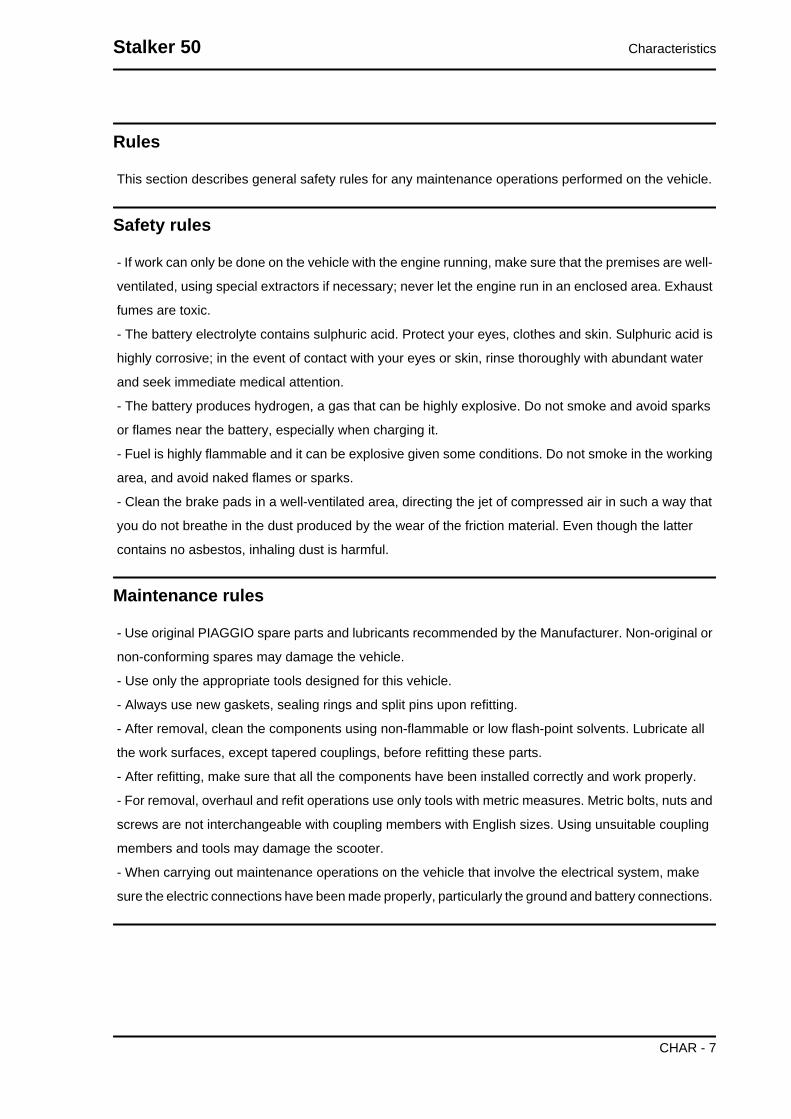
Rules
This section describes general safety rules for any maintenance operations performed on the vehicle.
Safety rules
- If work can only be done on the vehicle with the engine running, make sure that the premises are well-
ventilated, using special extractors if necessary; never let the engine run in an enclosed area. Exhaust
fumes are toxic.
- The battery electrolyte contains sulphuric acid. Protect your eyes, clothes and skin. Sulphuric acid is
highly corrosive; in the event of contact with your eyes or skin, rinse thoroughly with abundant water
and seek immediate medical attention.
- The battery produces hydrogen, a gas that can be highly explosive. Do not smoke and avoid sparks
or flames near the battery, especially when charging it.
- Fuel is highly flammable and it can be explosive given some conditions. Do not smoke in the working
area, and avoid naked flames or sparks.
- Clean the brake pads in a well-ventilated area, directing the jet of compressed air in such a way that
you do not breathe in the dust produced by the wear of the friction material. Even though the latter
contains no asbestos, inhaling dust is harmful.
Maintenance rules
- Use original PIAGGIO spare parts and lubricants recommended by the Manufacturer. Non-original or
non-conforming spares may damage the vehicle.
- Use only the appropriate tools designed for this vehicle.
- Always use new gaskets, sealing rings and split pins upon refitting.
- After removal, clean the components using non-flammable or low flash-point solvents. Lubricate all
the work surfaces, except tapered couplings, before refitting these parts.
- After refitting, make sure that all the components have been installed correctly and work properly.
- For removal, overhaul and refit operations use only tools with metric measures. Metric bolts, nuts and
screws are not interchangeable with coupling members with English sizes. Using unsuitable coupling
members and tools may damage the scooter.
- When carrying out maintenance operations on the vehicle that involve the electrical system, make
sure the electric connections have been made properly, particularly the ground and battery connections.
Stalker 50 Characteristics
CHAR - 7

Vehicle identification
Chassis prefix ZAPC40100 xxxx xxxxxxx
Engine prefix C401M xxxx
Dimensions and mass
WEIGHTS AND DIMENSIONSSpecification Desc./QuantityOverall length 1760 mm.Overall width 720 mm.
Maximum height 810 mm.Wheelbase 1230 mm.Kerb weight 87 kg
Characteristics Stalker 50
CHAR - 8

Engine
ENGINESpecification Desc./QuantityEngine type Two-stroke, single cylinder Piaggio Hi-PER2
Bore x stroke 40 X 39.3 mmCubic capacity 49.40 cc
Compression ratio 9.4 to 10.4 :1Carburettor DELL'ORTO PHVA 17.5 RD
CO adjustment 3.5% ± 0.5Engine idle speed 1800 to 2000 r.p.m.
Air filter Sponge impregnated with fuel mixture (50% SELENIA air filteroil and 50% unleaded petrol).
Starting system electric starter/kickstarterLubrication With blend and variable oil variable according to the engine
revolutions and the throttle valve opening by means of a pumpcontrolled by the driving shaft with toothed belt.
Fuel supply With vacuum operated cock, lead-free gasoline (with 95 octaneminimum) by means of the carburettor.
Cooling Forced air circulation.
Transmission
TRANSMISSIONSpecification Desc./QuantityTransmission With automatic expandable pulley variator, torque server, V
belt, automatic clutch, gear reduction unit.
Stalker 50 Characteristics
CHAR - 9

Capacities
CAPACITYSpecification Desc./Quantity
Fuel tank Plastic, with a capacity of 6 litres (approximate value) includingreserve of ~ 1.5 l.
Oil mixer tank Plastic, with a capacity of ~ 1.2 l. (including a ~0.400 l reserve).Rear hub oil Quantity: approx. 75 cm³
Electrical system
ELECTRICAL SYSTEMSpecification Desc./Quantity
Type of ignition Capacitive discharge type electronic ignition, with incorporatedhigh voltage coil
Ignition advance (before TDC) Fixed 17° ± 1Recommended spark plug CHAMPION RN2C
Battery 12V-4AhMain fuse 7.5 AGenerator In alternate current with three output sections
Frame and suspensions
FRAME AND SUSPENSIONSSpecification Desc./QuantityChassis type Welded tubular steel chassis with stamped sheet reinforce-
mentsFront suspension upside-down hydraulic telescopic fork.
Front stroke 73 mmFront suspension stroke 58 mm
Rear suspension With coaxial spring and hydraulic shock absorber. Chassis toengine support with swinging arm.
Brakes
BRAKESSpecification Desc./QuantityFront brake Disc D=190 mm with hydraulic control, operated by right brake
lever on the handlebars.Rear brake Drum D=110 mm with expansion brake shoes, mechanically
controlled by the left brake lever on the handlebars.
Wheels and tyres
WHEELS AND TYRESSpecification Desc./Quantity
Front tyre Tubeless 120/90 x -10''Rear tyre Tubeless 130/90 x -10''Wheels with 3.50x10" wheel rims in light alloy.
Carburettor
Characteristics Stalker 50
CHAR - 10

50cc Version
Dell'Orto
ORTO CARBURETTORSpecification Desc./Quantity
Type PHVA 17.5 RDDiffuser diameter Ø 17.5
Regulation reference number 8423Maximum nozzle: 53
Maximum air nozzle (on the body): Ø 1.5Tapered pin stamped code: A22
Pin position (notches from above): 1Diffuser: 209 HA
Minimum nozzle: 32Minimum air nozzle (on the body): Free
Secondary minimum air hole Ø 2.5Initial minimum mix screw opening: 1 1/2
Starter jet 50Starter air nozzle (on the body): Ø 1.5
Stroke of starter pin: 11 mmGasoline inlet hole Ø 1.5
Tightening Torques
STEERING ASSEMBLYName Torque in Nm
Upper steering ring nut (safety locks) 35 to 40 NmLower steering ring nut (safety locks) 8 to 10 Nm
Handlebar fixing pin (safety locks) 45 to 50 Nm
FRAME ASSEMBLYName Torque in Nm
Swinging arm-engine pin (safety locks) 33 to 41 NmSwinging arm-frame pin (safety locks) 64 to 72 Nm
Shock absorber - frame nut (safety locks) 20 to 25 NmShock absorber-engine pin (safety locks) 33 to 41 Nm
Rear wheel axis (safety locks) 104 to 126 NmBolt holding stand to the engine 18 to 19 Nm
FRONT SUSPENSIONName Torque in Nm
Front wheel axle nut (safety locks) 45 to 50 NmWheel axle clamp screw 6 ÷ 7 Nm
Lower leg screw 15 to 20 NmHydraulic cartridge stem nut 15 to 18 Nm
FRONT BRAKEName Torque in Nm
Viti fissaggio coperchio pompa freno 1,5 ÷ 2 NmBrake pump support fixing screw 7 to 10 Nm
Brake fluid pump - hose fitting 13 to 18 NmBrake fluid tube - calliper fitting 20 to 25 Nm
Calliper tightening screw 20 to 25 NmDisc tightening screw (safety locks - lock with LOCTITE
THREADLOCK MEDIUM TYPE 243)6 ÷ 7 Nm
Oil bleed screw 7 to 10 NmCalliper coupling screw 20 to 25 Nm
Stalker 50 Characteristics
CHAR - 11

ENGINE ASSEMBLYName Torque in Nm
Clutch bell nut 40 to 44 NmClutch lock ring nut 55 ÷ 60
nut locking driving pulley on the crankshaft 40 to 44 NmStart-up lever screw 12 ÷ 13
Flywheel nut 40 to 44 NmFlywheel fan screws 3 ÷ 4
Half-crank case joint bolts 12 ÷ 13Bolts holding exhaust pipe to the crankcase 22 ÷ 24
Screws holding the filter box to the crank case 4 ÷ 5Head nuts 10 ÷ 11
Starter screws 12 ÷ 13Ignition spark plug 25 ÷ 30
Hub oil drainage cap 3 ÷ 5Oil hub level dipstick ManualRear hub cap screws 12 ÷ 13
Transmission cover screws 12 ÷ 13Inlet manifold screws 8 ÷ 9
Flywheel hood fixing screws 1 ÷ 2Cylinder hood fixing screws 3.5 ÷ 5
Stator clamping screws 3 ÷ 4Pick-Up clamping screw 4 ÷ 5Mixer clamping screws 3 ÷ 4
Screw fixing brake lever to the journal on the engine 12 ÷ 13
Overhaul data
Assembly clearances
Cylinder - piston assy.
COUPLING BETWEEN PISTON AND CYLINDERName Initials Cylinder Piston Play on fitting
Standard coupling M 40.005 - 40.012 39.943 - 39.95 0.055 - 0.069Standard coupling N 40.012 - 40.019 39.95 - 39.957 0.055 - 0.069Standard coupling O 40.019 - 40.026 39.957 - 39.964 0.055 - 0.069Standard coupling P 40.026 - 40.033 39.964 - 39.971 0.055 - 0.069
coupling 1st oversize M1 40.205 - 40.212 40.143 - 40.15 0.055 - 0.069coupling 1st oversize N1 40.212 - 40.219 40.15 - 40.157 0.055 - 0.069coupling 1st oversize O1 40.219 - 40.226 40.157 - 40.164 0.055 - 0.069coupling 1st oversize P1 40.226 - 40.233 40.164 - 40.171 0.055 - 0.069
Coupling 2nd oversize M2 40.405 - 40.412 40.343 - 40.35 0.055 - 0.069Coupling 2nd oversize N2 40.412 - 40.419 40.35 - 40.357 0.055 - 0.069Coupling 2nd oversize O2 40.419 - 40.426 40.357 - 40.364 0.055 - 0.069Coupling 2nd oversize P2 40.426 - 40.433 40.364 - 40.371 0.055 - 0.069
Characteristics Stalker 50
CHAR - 12
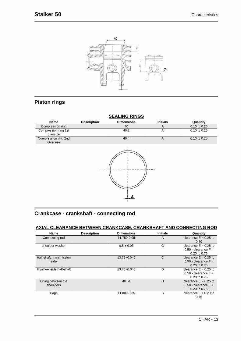
Piston rings
SEALING RINGSName Description Dimensions Initials Quantity
Compression ring 40 A 0.10 to 0.25Compression ring 1st
oversize40.2 A 0.10 to 0.25
Compression ring 2ndOversize
40.4 A 0.10 to 0.25
Crankcase - crankshaft - connecting rod
AXIAL CLEARANCE BETWEEN CRANKCASE, CRANKSHAFT AND CONNECTING RODName Description Dimensions Initials Quantity
Connecting rod 11.750-0.05 A clearance E = 0.25 to0.50
shoulder washer 0.5 ± 0.03 G clearance E = 0.25 to0.50 - clearance F =
0.20 to 0.75Half-shaft, transmission
side13.75+0.040 C clearance E = 0.25 to
0.50 - clearance F =0.20 to 0.75
Flywheel-side half-shaft 13.75+0.040 D clearance E = 0.25 to0.50 - clearance F =
0.20 to 0.75Lining between the
shoulders40.64 H clearance E = 0.25 to
0.50 - clearance F =0.20 to 0.75
Cage 11.800-0.35 B clearance F = 0.20 to0.75
Stalker 50 Characteristics
CHAR - 13

Slot packing system
- Fit the cylinder without installing the basic gasket.
- Apply a centimetre dial gauge on the special tool
and zero it on the ground plane
- Fit the tool to the top of the cylinder fixing it with
two nuts to the studbolts and take the piston to the
T.D.C.
- The thickness of the gasket to fit will change de-
pending on the value detected. For this purpose,
there are three with different thicknesses
Specific tooling020272Y Piston position check tool
SHIMMING SYSTEMName Measure A Thickness
Shimming 2.80 ÷ 3.04 0,4Shimming 3.04 ÷ 3.24 0,6Shimming 3.25 ÷ 3.48 0,8
Products
RECOMMENDED PRODUCTS TABLEProduct Description Specifications
AGIP ROTRA 80W-90 Rear hub oil SAE 80W/90 Oil that exceeds the re-quirements of API GL3 specifications
AGIP FILTER OIL Oil for air filter sponge Mineral oil with specific additives for in-creased adhesiveness
AGIP CITY TEC 2T Mixer oil synthetic oil for 2-stroke engines: JASOFC, ISO-L-EGD
AGIP GP 330 Grease for brake levers, throttle White calcium complex soap-basedspray grease with NLGI 2; ISO-L-XBCIB2
AGIP GREASE SM 2 Grease for the tone wheel revolving ring Soap-based lithium grease containingNLGI 2 Molybdenum disulphide; ISO-L-
XBCHB2, DIN KF2K-20AGIP BRAKE 4 Brake fluid FMVSS DOT 4 Synthetic fluid
MONTBLANC MOLYBDENUMGREASE
Grease for driven pulley shaft adjustingring and movable driven pulley housing
Grease with molybdenum disulphide
Characteristics Stalker 50
CHAR - 14

Product Description SpecificationsAGIP GREASE PV2 Grease for the steering bearings, pin
seats and swinging armWhite anhydrous-calcium based greaseto protect roller bearings; temperature
range between -20 C and +120 C; NLGI2; ISO-L-XBCIB2.
Stalker 50 Characteristics
CHAR - 15

INDEX OF TOPICS
TOOLING TOOL

TOOLSStores code Description
001330Y Tool for fitting steering seats
001467Y006 Pliers to extract 20 mm bearings
001467Y007 Driver for OD 54 mm bearing
001467Y009 Driver for OD 42-mm bearings
001467Y013 Pliers to extract ø 15-mm bearings
001467Y014 Pliers to extract ø 15-mm bearings
Stalker 50 Tooling
TOOL - 17

Stores code Description001467Y017 Bell for bearings, OD 39 mm
001467Y021 Extraction pliers for ø 11 mm bearings
002465Y Pliers for circlips
006029Y Punch for fitting fifth wheel seat on steer-ing tube
020004Y Punch for removing fifth wheels fromheadstock
020055Y Wrench for steering tube ring nut
020150Y Air heater support
Tooling Stalker 50
TOOL - 18

Stores code Description020151Y Air heater
020162Y Flywheel extractor
020163Y Crankcase splitting plate
020164Y Driven pulley assembly sheath
020165Y Start-up crown lock
020166Y Pin lock fitting tool
Stalker 50 Tooling
TOOL - 19

Stores code Description020261Y Starter spring fitting
020262Y Crankcase splitting strip
020265Y Bearing fitting base
020325Y Brake-shoe spring calliper
020329Y MityVac vacuum-operated pump
020330Y Stroboscopic light to check timing
Tooling Stalker 50
TOOL - 20

Stores code Description020331Y Digital multimeter
020332Y Digital rev counter
020334Y Multiple battery charger
020335Y Magnetic support for dial gauge
Stalker 50 Tooling
TOOL - 21

Stores code Description020350Y Electrical system check instrument
020357Y 32 x 35 mm adaptor020359Y 42x47-mm adaptor
020376Y Adaptor handle
020412Y 15 mm guide
020456Y Ø 24 mm adaptor
Tooling Stalker 50
TOOL - 22

Stores code Description020483Y 30 mm guide
020565Y Flywheel lock calliper spanner
020625Y Kit for sampling gas from the exhaustmanifold
Stalker 50 Tooling
TOOL - 23

INDEX OF TOPICS
MAINTENANCE MAIN

Maintenance chart
MAINTENANCE TABLEI: CHECK AND CLEAN, ADJUST, LUBRICATE OR REPLACE, IF NECESSARYC. CLEAN, R:REPLACE, A:ADJUST, L:LUBRICATEClean the SAS air filter every 2 years** Replace every 2 years
km x 1,000 1 5 10 15 20 25 30 35 40 45 50SAS filter I I I I ISteering A A A A A AOdometer gear L LIdle speed A A A A A AVehicle road test I I I I I I I I I I ISliding blocks / variable speed rollers I I I R I I I R I ITyre pressure and wear I I I I I I I I I I IBrake Pads/Shoes I I I I I I I I I I IHeadlight aiming adjustment A A A A AHub oil R I I I R I I I R I IBrake fluid ** I I I I I I I I I I IBrake control levers L L L L L LElectrical system and battery I I I I I I I I I I IAir filter C C C C C C C C C CThrottle control - mixer A A A A A ADriving belt I R I R I R I R I RSpark plug I R I R I R I R I RSafety locks I I I I I IDriven pulley roller casing L L L L LSuspensions I I I I ITransmissions L L L L L
Checking the spark advance
-Check to be made at over 4000 rpm with strobo-
scopic gun. The advanced ignition measured must
be 17° before the TDC.
- This value is correct when the reference mark on
the flywheel hood is aligned with the reference
mark on the cooling fan and the phase shifter on
the stroboscopic gun is set on 17°.N.B.IN CASE OF MALFUNCTION, CARRY OUT THE CHECKSPROVIDED FOR IN THE ELECTRICAL SYSTEM CHAPTER.CAUTIONBEFORE CARRYING OUT THE ABOVE CHECKS, CHECKTHE CORRECT KEYING OF THE FLYWHEEL ON THECRANKSHAFT.
Specific tooling020330Y Stroboscopic light to check timing
Stalker 50 Maintenance
MAIN - 25
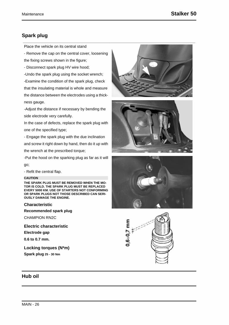
Spark plug
Place the vehicle on its central stand
- Remove the cap on the central cover, loosening
the fixing screws shown in the figure;
- Disconnect spark plug HV wire hood;
-Undo the spark plug using the socket wrench;
-Examine the condition of the spark plug, check
that the insulating material is whole and measure
the distance between the electrodes using a thick-
ness gauge.
-Adjust the distance if necessary by bending the
side electrode very carefully.
In the case of defects, replace the spark plug with
one of the specified type;
- Engage the spark plug with the due inclination
and screw it right down by hand, then do it up with
the wrench at the prescribed torque;
-Put the hood on the sparking plug as far as it will
go;
- Refit the central flap.CAUTIONTHE SPARK PLUG MUST BE REMOVED WHEN THE MO-TOR IS COLD. THE SPARK PLUG MUST BE REPLACEDEVERY 5000 KM. USE OF STARTERS NOT CONFORMINGOR SPARK PLUGS NOT THOSE DESCRIBED CAN SERI-OUSLY DAMAGE THE ENGINE.
CharacteristicRecommended spark plugCHAMPION RN2C
Electric characteristicElectrode gap0.6 to 0.7 mm.
Locking torques (N*m)Spark plug 25 - 30 Nm
Hub oil
Maintenance Stalker 50
MAIN - 26

Check
Do the following to check the correct level:
1) Stand the vehicle on the centre-stand on flat
ground;
2) Remove the dipstick «A», and dry it with a clean
cloth. Reinsert it, screwing it in all the way;
3) Remove the stick and check that the oil level is
slightly over the second notch starting from the
lower end;
4) Screw the dipstick back in, checking that it is
locked in place.
Recommended productsAGIP ROTRA 80W-90 Rear hub oilSAE 80W/90 Oil that exceeds the requirements of
API GL3 specifications
Replacement
-Remove the oil filler cap «A».
- Unscrew the oil drainage cap "B" and drain out
all the oil.
- Screw in the drainage cap again and fill the hub
with the prescribed oil.
CharacteristicRear hub oilQuantity: approx. 80 cm³
Stalker 50 Maintenance
MAIN - 27

Air filter
- Remove the left side panel.
- Remove the cap of the purifier, unscrewing the
six clamping screws and removing the filter.
Cleaning:
- Wash with water and neutral soap.
- Dry with a clean cloth and short blasts of com-
pressed air.
-Saturate with a 50% mixture of gasoline and oil.
-Drip dry the filter and then squeeze it between the
hands without wringing.
-Let it dry and refit it again.CAUTIONNEVER RUN THE ENGINE WITHOUT THE AIR FILTER,THIS WOULD RESULT IN AN EXCESSIVE WEAR OF THEPISTON AND CYLINDER.
Recommended productsAGIP FILTER OIL Oil for air filter spongeMineral oil with specific additives for increased ad-
hesiveness
transmissions
Odometer driving pinion connection
Remove the odometer cable and grease with the
recommended product.
Recommended productsAGIP GP 330 Grease for brake levers, throttleWhite calcium complex soap-based spray grease
with NLGI 2; ISO-L-XBCIB2
Maintenance Stalker 50
MAIN - 28

During this stage, the engine must be fed with a
2% mixture (at least 0.5 litres if the tank is empty).
- Remove the left side panel.
- Remove the front handlebar cover.
- Put the scooter in gear and adjust the idle speed
by turning the set screw on the carburettor.
- Adjust the control cables:
Handlebar control: remove the rubber hood and
regulate the cable adjustment in such a way that it
causes a minimum backlash on the throttle.
Carburettor control: remove the rubber hood and
regulate the cable adjustment in such a way that
the sheath has a minimum backlash.
Oil mixer control: remove the cap on the engine
crankcase and regulate the adjustment in such a
way that with the throttle released, the reference
mark on the rotating plate is lined up with the ref-
erence mark on the mixer body as indicated in the
figure.
- Twist the throttle to the end of the stroke a couple
of times and check that the adjustments have been
made properly, then lock all the adjustments.N.B.TO VERIFY THE CORRECT TIMING OF THE MIXER IT ISNECESSARY TO REMOVE THE AIR CONDUIT OF THETRANSMISSION COVER.CAUTIONIN CASE OF DISMANTLING OR RUNNING OUT OF OIL INTHE RESERVOIR BLEED THE MIXER AS FOLLOWS: RE-FILL THE OIL RESERVOIR WHEN THE MIXER IS FITTEDTO THE VEHICLE AND THE ENGINE IS OFF, UNDO THEMIXER PIPE FROM THE CARBURETTOR AND LOOSENTHE BLEED SCREWS (SEE THE ARROW IN THE FIGURE)UNTIL THE OIL BEGINS TO FLOW OUT. TIGHTEN THESCREWS, START UP THE ENGINE AND WAIT FOR OIL TOFLOW OUT OF THE TUBE. RECONNECT THE DELIVERYPIPE TO THE CARBURETTOR AND FIX IT IN PLACE WITHTHE RELEVANT METAL CLIP.
Recommended productsAGIP CITY TEC 2T Mixer oilsynthetic oil for 2-stroke engines: JASO FC, ISO-
L-EGD
Stalker 50 Maintenance
MAIN - 29
Braking system
Level check
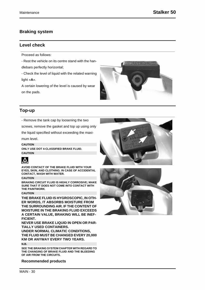
Proceed as follows:
- Rest the vehicle on its centre stand with the han-
dlebars perfectly horizontal;
- Check the level of liquid with the related warning
light «A».
A certain lowering of the level is caused by wear
on the pads.
Top-up
- Remove the tank cap by loosening the two
screws, remove the gasket and top up using only
the liquid specified without exceeding the maxi-
mum level.CAUTIONONLY USE DOT 4-CLASSIFIED BRAKE FLUID.CAUTION
AVOID CONTACT OF THE BRAKE FLUID WITH YOUREYES, SKIN, AND CLOTHING. IN CASE OF ACCIDENTALCONTACT, WASH WITH WATER.CAUTIONBRAKING CIRCUIT FLUID IS HIGHLY CORROSIVE; MAKESURE THAT IT DOES NOT COME INTO CONTACT WITHTHE PAINTWORK.CAUTION
THE BRAKE FLUID IS HYGROSCOPIC, IN OTH-ER WORDS, IT ABSORBS MOISTURE FROMTHE SURROUNDING AIR. IF THE CONTENT OFMOISTURE IN THE BRAKING FLUID EXCEEDSA CERTAIN VALUE, BRAKING WILL BE INEF-FICIENT.NEVER USE BRAKE LIQUID IN OPEN OR PAR-TIALLY USED CONTAINERS.UNDER NORMAL CLIMATIC CONDITIONS,THE FLUID MUST BE CHANGED EVERY 20,000KM OR ANYWAY EVERY TWO YEARS.N.B.SEE THE BRAKING SYSTEM CHAPTER WITH REGARD TOTHE CHANGING OF BRAKE FLUID AND THE BLEEDINGOF AIR FROM THE CIRCUITS.
Recommended products
Maintenance Stalker 50
MAIN - 30

AGIP BRAKE 4 Brake fluidFMVSS DOT 4 Synthetic fluid
Headlight adjustment
Proceed as follows:
1. Place the vehicle in riding condition and with the
tyres correctly inflated on a flat piece of ground at
a distance of 10 m from a white screen situated in
a shaded area, making sure that the scooter is
perpendicular to the screen;
2. Turn on the headlight and check that the edge
of the beam projected on the screen is not more
than 9/10 of the height of the centre of the head-
light from the ground, and not less than 7/10;
3. If this is not the case, remove the hook by turning
the two screws, then remove the cover on the
shield back plate.
Adjust the headlight by turning screw "A".N.B.THE ABOVE PROCEDURE COMPLIES WITH THE EURO-PEAN STANDARDS REGARDING MAXIMUM AND MINI-MUM HEIGHT OF LIGHT BEAMS. REFER TO THE STATU-TORY REGULATIONS IN FORCE IN EVERY COUNTRYWHERE THE vehicle IS USED.
Stalker 50 Maintenance
MAIN - 31

INDEX OF TOPICS
TROUBLESHOOTING TROUBL

This section makes it possible to find the solutions to use in troubleshooting.
For each breakdown, a list of the possible causes and respective interventions is given.
Engine
Poor performance
POOR PERFORMANCEPossible Cause Operation
Defective fuel cock or vacuum hose damaged. Replace the cock or the control hose.Carburettor nozzles clogged or dirty Dismantle, wash with solvent and dry with compressed air
Fuel filter on the tank outlet fitting dirty or clogged Clean the fitting filterExcess of encrustations in the combustion chamber Remove the encrustations
Lack of compression wear of the piston rings or cylinder Check the worn parts and replace themExhaust pipe clogged due to excessive encrustations Replace the exhaust pipe and check the carburation and mixer
timerAir filter blocked or dirty Clean according to the procedure
Starter inefficient (stays on) Check the mechanical sliding, continuity of the circuit, the pres-ence of power and electrical wiring
Clutch slipping Check the centrifugal brake shoe assembly and /or clutch belland replace if necessary
Defective mobile pulley sliding Check the parts, change the faulty parts and lubricate the driv-en pulley using only Montblanc-Molibdenum Grease (dis.
498345) greaseTransmission belt worn Replace
Roller wear; Presence of oil; Dirt Clean the speed variator, replace the rollers if worn out
Rear wheel spins at idle
REAR WHEELPossible Cause Operation
Idling rpms too high Check the idling speed and, if necessary, adjust the C.O.Clutch fault Check the spring/friction mass and the clutch bell
Air filter housing not sealed Correctly refit the filter housing and replace it if it is damaged
Starting difficulties
DIFFICULTY STARTINGPossible Cause Operation
Carburettor nozzles clogged or dirty Dismantle, wash with solvent and dry with compressed airDefective fuel cock or vacuum hose damaged. Replace the cock or the control hose.
Starter inefficient Check: electric wiring, circuit continuity, mechanical sliding andpower supply
Battery flat Check the state of the battery. If it shows signs of sulphationreplace it and bring the new battery into service charging it foreight hours at a current of 1/10 of the capacity of the battery
itself- Engine flooded. Start up keeping the throttle fully open alternating approximate-
ly five seconds of turning it with five seconds still. If however itdoes not start, remove the spark plug, the engine over with thethrottle open being careful to keep the cap in contact with thespark plug and the spark plug grounded but away from its hole.
Refit a dry spark plug and start the vehicle.Altered fuel characteristics Drain off the fuel no longer up to standard; then, refill
Defective spark plug or with incorrect electrode gap Remove the encrustation, restore the plug gap or replace beingsure to use the types of spark plug recommended at all times.
Stalker 50 Troubleshooting
TROUBL - 33

Possible Cause OperationBear in mind that many problems engines have, derive from
the use of the wrong spark plugIntake joint cracked or with a bad seal Replace the intake joint and check its tightness on the crank-
case and on the carburettorPurifier-carburettor fitting damaged Replace
Excessive oil consumption/Exhaust smoke
EXCESSIVE OIL CONSUMPTION/SMOKEY EXHAUSTPossible Cause Operation
Excess of encrustations in the combustion chamber Remove the encrustations
Engine tends to cut-off at full throttle
ENGINE STOP FULL THROTTLEPossible Cause Operation
Maximum nozzle dirty - lean mixture Wash the nozzle with solvent and dry with compressed airDirty carburettor Wash the carburettor with solvent and dry with compressed air
Water in the carburettor Empty the tank through the appropriate bleed nipple.Air filter dirty Clean or replace
Defective floating valve Check the proper sliding of the float and the functioning of thevalve
Tank breather hole obstructed Restore the proper tank aeration
Engine tends to cut-off at idle
ENGINE STOP IDLINGPossible Cause Operation
Minimum nozzle dirty Wash the nozzle with solvent and dry with compressed airStarter that stays open Check: electric wiring, circuit continuity, mechanical sliding and
power supplyReed valve does not close Check / replace the reed packWrong idling adjustment Correctly adjust the engine idling and check the level of the
C.O.Spark plug defective or faulty Replace the spark plug with one with the specified degree and
check the plug gap
Excessive exhaust noise
INCREASED NOISINESSPossible Cause Operation
Secondary metal air pipe deteriorated Check the seal of the piping on the crankcase and on the hous-ing, check the piping between the housing and the muffler.
Good condition of the missing secondary air circuit components Check the individual components and the piping, check theprecision of the fitting. Replace the damaged components
High fuel consumption
HIGH FUEL CONSUMPTIONPossible Cause Operation
Air filter blocked or dirty. Clean according to the procedure
Troubleshooting Stalker 50
TROUBL - 34

Possible Cause OperationStarter inefficient Check: electric wiring, circuit continuity, mechanical sliding and
power supply
SAS malfunctions
SLACKENING OF THE RUBBER JOINT OF THE SECONDARY AIR PIPE ON THE MUF-FLER
Possible Cause OperationSecondary air reed blocking ReplaceSecondary air filter clogging Clean the filter and the housing
Blockage of the secondary air fitting on the muffler Remove the encrustations from the joint being careful not to letthe debris fall into the muffler
Transmission and brakes
Clutch grabbing or performing inadequately
CLUTCHPossible Cause Operation
Tear or irregular functioning Check that the masses open and return normallyCheck that there is no grease on the masses
Check that the clutch masses' contact surface withthe clutch bell is mainly in the middle with charac-
teristics equivalent on the three massesCheck that the clutch bell is not scored or worn
abnormallyNever operate the engine without the clutch bell
Insufficient braking
BRAKING SYSTEM MALFUNCTIONPossible Cause Operation
Poor braking The rear (drum type) brake is adjusted by regulating the specialadjustment (on the wheel) bearing in mind that, with the control
levers in the rest position, the wheels must turn freely.The braking action should begin when the brake
levers are pressed by about a third.Check the brake pad wear.
If it is not possible to remove any problems by sim-ply adjusting the transmissions, check the brake
pads and front brake disc, the brake shoes and therear drum. If you encounter excessive wear orscoring, make the necessary replacements.
Air bubbles inside the hydraulic braking system Carefully bleed the hydraulic braking system, (there must beno flexible movement of the brake lever).
Fluid leakage in hydraulic braking system Elastic fittings, piston seals or brake pump breakdown, replaceThe brake fluid has lost its properties Replace the front brake fluid and top up to the correct level in
the pumpDefective sliding of the cables in their sheathes Lubricate or substitute
Brake noise Check the wear of the brake pads and/or shoes
Stalker 50 Troubleshooting
TROUBL - 35

Brakes overheating
BRAKES OVERHEATINGPossible Cause Operation
Defective piston sliding Check calliper and replace any damaged part.Brake disc or drum deformed Using a dial gauge, check the planarity of the disk with the
wheel correctly fitted or the concentricity of the rear drum.
Electrical system
Battery
BATTERYPossible Cause Operation
Battery The battery is the electrical device in the system that requiresthe most frequent inspections and thorough maintenance. If thevehicle is not used for some time (1 month or more) the battery
needs to be recharged periodically. The battery runs downcompletely in the course of 5 ÷ 6 months. If the battery is fittedon a motorcycle, be careful not to invert the connections, keep-
ing in mind that the black ground wire is connected to thenegative terminal while the red wire is connected to the terminalmarked+. Follow the instructions in the ELECTRICAL SYSTEM
chapter for the recharging of the batteries.
Steering and suspensions
Rear wheel
POOR ROAD HOLDINGPossible Cause Operation
Faulty suspension Check that the rear shock absorber and/or the front fork is/arein good working order. Replace or overhaul the front fork and/
or replace the rear shock absorbers in case of malfunctionTyres deflated or damaged Check the correct pressure of the tyres and the condition of the
tread. Inflate to the correct pressure or replace.Loosen the anchorage points of the front and/or rear suspen-
sion unit.Check the tightness between the frame, swinging arm and en-gine and the fixing of the wheels to the hub and/or the axle.
Check the correct tightening of the steering ring nut.
Heavy steering
STEERING HARDENINGPossible Cause Operation
Torque not conforming Check the tightening of the top and bottom ringnuts.
If irregularities continue in turning the steeringeven after making the above adjustments, checkthe seats in which the ball bearings rotate: replace
if they are recessed.
Troubleshooting Stalker 50
TROUBL - 36

Excessive steering play
EXCESSIVE STEERING CLEARANCEPossible Cause Operation
EXCESSIVE STEERING CLEARANCE Check the tightening of the top and bottom ringnuts.
If irregularities continue in turning the steeringeven after making the above adjustments, checkthe seats in which the ball bearings rotate: replace
if they are recessed.
Noisy suspension
NOISY SUSPENSIONPossible Cause Operation
Components of the front suspension damaged. Check the quiet operation in the compression or release pha-ses of the fork and if necessary overhaul it. Check that there isno noise or seizing during the wheel rotation; if there is, change
the wheel bearing.Components of the rear suspension damaged. Check the absence of noise in the compression or release of
the suspension, if necessary check the proper tightness to theswinging arm unit and the absence of rust or replace the entireshock absorber. Check that there is no noise or seizing duringthe wheel rotation; if there is noise or seizing overhaul the final
reduction assembly.
Suspension oil leakage
OIL LEAKAGE FROM SUSPENSIONPossible Cause Operation
Shock absorbers malfunctioning Replace the complete shock absorption unitHydraulic cartridge in the fork damaged. Replace the hydraulic cartridge
Stalker 50 Troubleshooting
TROUBL - 37

INDEX OF TOPICS
ELECTRICAL SYSTEM ELE SYS

LEGEND:
1. Electronic ignition device
2. Spark plug
3. Magneto flywheel
4. Voltage regulator
5. Main fuse
6. Key switch
7. Battery
8. Starter motor
9. Starter remote control
10. Starter button
11. STOP button on rear brake
12. STOP button on front brake
13. Horn button
14. Horn
15. Left turn rear indicator lamp
16. Tail light/stop light lamp
17. Turn indicator switch
18. Right turn rear indicator lamp
19. Left turn front indicator lamp
Stalker 50 Electrical system
ELE SYS - 39

20. Front headlight assembly
A. Tail light
B. High beam/low beam lamp
21. Right turn front indicator lamp
22. Light switch
23. Instrument panel
A. Flashing warning light
B. Instrument panel lamp and lights warning light
C. Fuel gauge
D. Low fuel warning light
E. Mixer oil warning light
F. High-beam warning light
24. Fuel level transmitter
25. Automatic starter
26. Oil warning light control
COLOUR CODES:
Or: Orange Lb: Light Blue Wh: White Bl: Blue Ye: Yellow Gr:Grey
Br:Brown Bl: Black Pi: Pink Re: Red Gre: Green Pu: Purple
Components arrangement
Voltage regulator
In order to access the voltage regulator it is nec-
essary to remove the shield back plate.
H.V. coil
In order to access the H.V. coil it is necessary to
remove the central chassis cover.
Electrical system Stalker 50
ELE SYS - 40

Starter remote control
In order to access the starter remote control it is
necessary to remove the left side panel.
Conceptual diagrams
Ignition
LEGEND:
1. Electronic ignition device
2. Spark plug
3. Magneto flywheel
6. Key switch
Stalker 50 Electrical system
ELE SYS - 41

Headlights and automatic starter section
LEGEND:
3. Magneto flywheel
4. Voltage regulator
16. Tail light/stop light lamp
20. Front headlight assembly
A. Tail light
B. High beam/low beam lamp
22. Light switch
23. Instrument panel
A. Flashing warning light
B. Instrument panel lamp and lights warning light
C. Fuel gauge
D. Low fuel warning light
E. Mixer oil warning light
F. High-beam warning light
25. Automatic starter
Electrical system Stalker 50
ELE SYS - 42

Battery recharge and starting
LEGEND:
3. Magneto flywheel
4. Voltage regulator
5. Main fuse
6. Key switch
7. Battery
8. Starter motor
9. Starter remote control
10. Starter button
11. STOP button on rear brake
12. STOP button on front brake
16. Tail light/stop light lamp
26. Oil warning light control
Stalker 50 Electrical system
ELE SYS - 43

Level indicators and enable signals section
LEGEND:
3. Magneto flywheel
4. Voltage regulator
5. Main fuse
6. Key switch
7. Battery
23. Instrument panel
A. Flashing warning light
B. Instrument panel lamp and lights warning light
C. Fuel gauge
D. Low fuel warning light
E. Mixer oil warning light
F. High-beam warning light
24. Fuel level transmitter
26. Oil warning light control
Electrical system Stalker 50
ELE SYS - 44

Turn signal lights
LEGEND:
3. Magneto flywheel
4. Voltage regulator
5. Main fuse
6. Key switch
7. Battery
13. Horn button
14. Horn
15. Left turn rear indicator lamp
17. Turn indicator switch
18. Right turn rear indicator lamp
19. Left turn front indicator lamp
21. Right turn front indicator lamp
23. Instrument panel
A. Flashing warning light
B. Instrument panel lamp and lights warning light
C. Fuel gauge
D. Low fuel warning light
Stalker 50 Electrical system
ELE SYS - 45

E. Mixer oil warning light
F. High-beam warning light
Instruments and warning lights control board
LEGEND:
A= Speedometer
B= Odometer
C= Headlight warning light
D= Turn indicator warning light;
E= Digital clock
F= Clock setting buttons
G= Low fuel warning light
H= Oil mix reserve warning light
I= High-beam headlight warning light
L= Fuel gauge
To remove the instrument, loosen the three
screws, disconnect the odometer cable joint O,
and connectors M and N.
Checks and inspections
Checks to be made in the case of ignition irregularities and/or no spark on the spark plug
1. Check the condition of the spark plug (clean it with a metal brush, remove the encrustations, blast
it with compressed air and, if necessary, replace it).
Electrical system Stalker 50
ELE SYS - 46

2. Without removing the stator, carry out the following checks:
After visually checking the electrical wiring, perform measurements on the loading reel, the pickup (see
chart) and the continuity using the appropriate tester.
If checks on the loading reel, pickup and continuity show abnormalities, replace the stator; otherwise
replace the central unit. Remember that disconnections due to replacement of the central unit must be
done with the engine off.
Specific tooling020331Y Digital multimeter
CHECK ON THE PICK UPSpecification Desc./Quantity
1 Red and white cable 90±140 ohm
RECHARGE COIL CHECK UPSpecification Desc./Quantity
1 Yellow and blue cable 800±1100 ohm
CHECK CONTINUITYSpecification Desc./Quantity
1 White cable-frame continuity2 White cable-engine continuity
Stalker 50 Electrical system
ELE SYS - 47

Ignition circuit
All the control operations of the system that require
the disconnection of cables (checks of the con-
nections and the devices making up the ignition
circuit) must be done with the engine off: if this is
not done, the controls might be irreparably dam-
aged.
Stator check
- Using a tester, check the resistance between the
red-ground and green-ground terminal.N.B.VALUES ARE STATED AT AMBIENT TEMPERATURE. ACHECK WITH THE STATOR AT OPERATING TEMPERA-TURE LEADS TO VALUES HIGHER THAN THOSE STATED.
Electric characteristicStator : green - ground~ 1 Ω (Stator)
Pick-Up: red - groundapprox. 170 Ω (Pick-Up)
Voltage regulator check
The malfunctioning of the voltage regulator might cause the following problems depending on the type
of fault:
1. The lighting system bulbs burn out.
2. The lighting system bulbs stop working.
3. The battery overcharges (the main fuse blows).
4. Non-recharging of the battery.
5. Non functioning of the turn indicators.
Electrical system Stalker 50
ELE SYS - 48

Measures
FAULT 1
Replace the regulator because it is certainly inef-
ficient.
FAULT 2
Check the efficiency of the bulbs.
With the vehicle in gear, check the battery voltage
on the yellow-black cable of the light switch. If
there is no voltage check the presence of voltage
between the yellow-black cable on the regulator
and ground. If there is voltage here, the fault needs
to be sought in the wiring from the regulator to the
light switch or the correct supply of voltage to the
stator is to be checked: without disconnecting the
regulator connector and with the vehicle in gear,
using the tester for alternate voltage readings
check that the voltage supplied between the con-
nection of the grey-blue cable (pin 2) and the black
cable (pin 6) is within the values indicated. If faults
are detected, replace the stator.
If no faults are detected in the controls carried out,
replace the regulator.
If functioning is still not correct even when the reg-
ulator is replaced, check the connections of the
electrical system.
Specific tooling020331Y Digital multimeter
CharacteristicVoltage distributed at 3000 rpms25 to 30V
FAULT 3
After checking that there are no short circuits in the system towards the earth, replace the regulator
because it is certainly inefficient and replace it with a protective fuse.
Following the replacement, measure the current and the recharging voltage on the battery end.
Stalker 50 Electrical system
ELE SYS - 49

FAULT 4
Put the vehicle in gear and check when the tester
for the detection of alternate voltages put between
the blue cable connection and the yellow cable
connection on the stator, the voltage distributed by
the generator is within the values indicated. In the
case of malfunction, check the continuity of the
stator or continue with the tests.
Insert an ammeter between the stator (blue cable)
and the battery and check, with the tester, that the
current is properly distributed at 3000 rpm and the
battery is kept between 12 and 13V as indicated.
If the values detected are lower than those speci-
fied, replace the regulator; otherwise replace the
battery.N.B.BEFORE CARRYING OUT THE CHECKS ON THE REGU-LATOR AND RELATIVE SYSTEM, IT IS ALWAYS GOODPRACTICE TO CHECK THAT THERE IS CONTINUITY BE-TWEEN THE BLACK CABLE AND THE GROUND.N.B.TO KEEP THE BATTERY BETWEEN 12 AND 13V, CAUSINGCURRENT ABSORPTION BY THE SYSTEM, A 12V - 35WBULB CONNECTED BETWEEN THE + BATTERY ANDGROUND CAN BE USED.
Specific tooling020331Y Digital multimeter
CharacteristicDistributed current1.5 to 2A
Voltage distributed at 3000 rpms25 to 30V
FAULT 5
If the turn indicators do not work, do the following:
• Without removing the connector from
the voltage regulator, move the key-
controlled switch to ON and verify the
presence of intermittent voltage be-
tween contact 7 and the ground. If
there is voltage, the failure must be at-
tributed to the flashing indicator switch
Electrical system Stalker 50
ELE SYS - 50

or the wiring, otherwise carry on with
tests.
• With the engine off, remove the regu-
lator connector, and insert the ends of
the tester between contact 5 and the
ground.
• Move the key controlled switch to ON
and check there is battery voltage. If no
voltage is detected, check the wiring
and the contacts on the key switch and
on the battery.
• Repeat the same procedure with the
ends of the tester inserted between
contact 5 (+) and 6 (-) and check the
presence of the battery voltage with the
key switch at on. If this does not hap-
pen, check the regulator's ground ca-
ble harness.
• If these last two tests have a positive result replace the regulator because it is certainly not
functioning properly.
Specific tooling020331Y Digital multimeter
Fuses
The electrical system is protected by a fuse con-
nected on the left-hand side of the helmet com-
partment next to the battery. For access it is
necessary to remove the battery cover and the
transparent protection over the fuse block. The ig-
nition system, headlight and the rear tail light are
not fuse-protected.CAUTION
BEFORE REPLACING THE BLOWN FUSE,SEARCH AND ELIMINATE THE BREAKDOWNTHAT HAS LED TO THE BLOW OUT.NEVER TRY TO REPLACE A FUSE USING DIF-FERENT MATERIAL (FOR EXAMPLE A PIECE
Stalker 50 Electrical system
ELE SYS - 51

OF ELECTRIC WIRE) OR A FUSE FOR A HIGH-ER AMPERAGE THAN THE INDICATED ONE.
Electric characteristicFuse7.5 A
Sealed batteryUsing the sealed battery for the first time
INSTRUCTIONS FOR REFRESHING THE STOCK CHARGE OF AN OPEN CIRCUIT
1) Voltage check
Before installing the battery on the vehicle, check the open circuit voltage with a normal tester.
- If the voltage exceeds 12.60 V, the battery may be installed without any renewal recharge.
- If voltage is below 12.60 V, a renewal recharge is required as explained in 2).
2) Constant voltage battery charge mode
-Constant voltage equal to 14.40÷14.70V
-Initial charge voltage equal to 0.3÷0.5 for nominal capacity
-Duration of the charge: 10 to 12 h recommended
Minimum 6 h
Maximum 24 h
3) Constant current battery charge mode
-Charge current equal to 1/10 of the nominal capacity of the battery
-Duration of the charge: 5 hWARNING-WHEN THE BATTERY IS REALLY FLAT (WELL BELOW 12.6V) IT MIGHT BE THAT 5 HOURS OFRECHARGING ARE NOT ENOUGH TO ACHIEVE OPTIMAL PERFORMANCE.IN THESE CONDITIONS IT IS HOWEVER ESSENTIAL NOT TO EXCEED EIGHT HOURS OF CON-TINUOUS RECHARGING SO AS NOT TO DAMAGE THE BATTERY ITSELF.
Dry-charge batteryWARNINGTHE BATTERY ELECTROLYTE IS POISONOUS AS IT MAY CAUSE SERIOUS BURNS. IT CON-TAINS SULPHURIC ACID. AVOID CONTACT WITH THE EYES, THE SKIN AND CLOTHING. IFCOMING INTO CONTACT WITH EYES OR SKIN, WASH ABUNDANTLY WITH WATER FOR AP-PROX. 15 MIN. AND SEEK IMMEDIATE MEDICAL ATTENTION.IN THE EVENT OF ACCIDENTAL INGESTION OF THE LIQUID, IMMEDIATELY DRINK LARGEQUANTITIES OF WATER OR MILK, MAGNESIUM MILK, BATTERED EGG OR VEGETABLE OIL.SEEK IMMEDIATE MEDICAL ATTENTION.THE BATTERIES PRODUCE EXPLOSIVE GAS; KEEP CLEAR OF NAKED FLAMES, SPARKS ORCIGARETTES; VENTILATE THE AREA WHEN RECHARGING INDOORS.
Electrical system Stalker 50
ELE SYS - 52

ALWAYS WEAR EYE PROTECTION WHEN WORKING IN THE PROXIMITY OF BATTERIES.KEEP OUT OF REACH OF CHILDREN
Use of dry-cell batteries :
1. Having removed the short, closed tube and removed the caps, put into the elements sulphuric
acid of the type for specific weight 1.26 accumulators corresponding to 30° Bé at a temperature
of no less than 15°, until you reach the upper level.
2. Leave to stand for at least 2 hours; afterwards top-up to the level with sulphuric acid.
3. Within twenty four hours, recharge with the special (single or multiple) battery charger that re-
charges at an intensity the same as approximately 1/10 the rated capacity of the said battery. At
the end of the charge, make sure that the density of the acid is around 1.27, corresponding to 31°
Bé and that these values are stabilised.
4. Once the charge is over, level the acid (by adding distilled water). Close and clean carefully.
5. Once the above operations have been performed, install the battery in the vehicle ensuring that
it is wired up properly..WARNING
- ONCE THE BATTERY HAS BEEN INSTALLED IN THE VEHICLE IT IS NECESSARY TO REPLACETHE SHORT TUBE (WITH CLOSED END) NEAR THE + POSITIVE TERMINAL WITH THE CORRE-SPONDING LONG TUBE (WITH OPEN END), THAT YOU FIND FITTED TO THE VEHICLE, TOENSURE THAT THE GASES THAT FORM CAN ESCAPE PROPERLY.
Specific tooling020333Y Single battery charger
020334Y Multiple battery charger
1 Hold the vertical tube
2 Look at the level
3 The float must be freed
Battery maintenance
The battery is an electrical device which requires careful monitoring and diligent maintenance. The
maintenance rules are:
1) Check the level of the electrolyte
The electrolyte level must be checked frequently and must reach the upper level. Only use distilled
water, to restore this level. If it is necessary to add water too frequently, check the vehicle's electrical
system: the battery works overcharged and is subject to quick wear.
2)Load status check
After restoring the electrolyte level, check its density using an appropriate densitometer (see the figure).
Stalker 50 Electrical system
ELE SYS - 53

When the battery is charged, you should detect a density of 30 to 32 Bé corresponding to a specific
weight of 1.26 to 1.28 at a temperature of no lower than 15° C.
A density reading of less than 20° Bé indicates that the battery is completely flat and it must therefore
be recharged.
If the scooter is not used for a given time (1 month or more) it will be necessary to periodically recharge
the battery.
The battery runs down completely in the course of three months. If it is necessary to refit the battery in
the vehicle, be careful not to reverse the connections, remembering that the ground wire (black) marked
(-) must be connected to the -negative clamp while the other two red wires marked (+) must be con-
nected to the clamp marked with the +positive sign.
3) Recharging the battery
Remove the battery from the vehicle removing the negative clamp first.
The normal bench charging must be carried out with the specific (single or multiple) battery charger,
placing the battery charger selector on the type of battery to be recharged. The connections to the power
supply must be made by connecting to the corresponding poles (+ with+ and -with -).
4) Battery cleaning
The battery should always be kept clean, especially on its top side, and the terminals should be coated
with Vaseline.WARNING
BEFORE RECHARGING THE BATTERY, REMOVE THE PLUGS OF EACH CELL. KEEP SPARKSAND NAKED FLAMES AWAY FROM THE BATTERY WHILE RECHARGING.CAUTION
NEVER USE FUSES WITH A CAPACITY HIGHER THAN THE RECOMMENDED CAPACITY. USINGA FUSE OF UNSUITABLE RATING MAY SERIOUSLY DAMAGE THE VEHICLE OR EVEN CAUSEA FIRE.CAUTION
ORDINARY AND DRINKING WATER CONTAINS MINERAL SALTS THAT ARE HARMFUL FORTHE BATTERY. FOR THIS REASON, YOU MUST ONLY USE DISTILLED WATER.CAUTION
CHARGE THE BATTERY BEFORE USE TO ENSURE OPTIMUM PERFORMANCE. INADEQUATECHARGING OF THE BATTERY WITH A LOW LEVEL OF ELECTROLYTE BEFORE IT IS FIRSTUSED SHORTENS THE LIFE OF THE BATTERY.
Specific tooling020334Y Multiple battery charger
020333Y Single battery charger
Electrical system Stalker 50
ELE SYS - 54

INDEX OF TOPICS
ENGINE FROM VEHICLE ENG VE

Removal of the engine from the vehicle
1) Disconnect the battery
2) Remove the full muffler.
3) Remove the rear wheel.
4) Remove the rear brake mechanical transmis-
sion.
5) Disconnect the electrical system connector from
the magneto flywheel, from the starter and from
the automatic starter.
6) Disconnect the accelerator and mixer control
transmissions.
7) Disconnect the mixer oil, fuel pipes and vacuum
pump control on the carburettor.
8) Disconnect the high-voltage cable from the
spark plug.
9) Remove the bolt fixing the rear shock absorber
from the engine.
10) Undo the nut on the right-hand side then re-
move the engine-swinging arm fixing pin from the
left-hand side.
Locking torques (N*m)Engine-swinging arm bolt 33 ÷ 41 Shock absorb-er-engine pin 33 to 41 Nm Rear wheel axle nut 104÷ 126
Engine from vehicle Stalker 50
ENG VE - 56

Stalker 50 Engine from vehicle
ENG VE - 57

INDEX OF TOPICS
ENGINE ENG

Automatic transmission
Transmission cover
- Loosen the 15 screws and remove the transmis-
sion cover with the aid of a mallet.N.B.THE CRANKCASE IS SLIGHTLY BLOCKED BY THE TIGHTFIT BETWEEN THE SHAFT OF THE DRIVEN HALF-PULLEYAND THE BEARING HOUSED ON THE CRANKCASE.
Kickstart
- Upon refitting, apply the recommended grease to
the bushing, to the spring and along the toothed
sector.
- Use the special tool for the charging of the spring,
as shown in the figure.
- Refit the seeger ring after checking that it is in
good condition.
Specific tooling020261Y Starter spring fitting
Recommended productsAGIP GREASE MU3 Grease for odometertransmission gear caseSoap-based lithium grease with NLGI 3; ISO-L-
XBCHA3, DIN K3K-20
- Remove the screws shown in the figure and re-
move the engine starting lever.
- For the assembly, work in reverse and tighten the
screws to the prescribed torque..
Locking torques (N*m)Starter lever replacement 12 to 13 Nm
Stalker 50 Engine
ENG - 59

- Remove the seeger ring located on the exterior
of the crankshaft.
- Dismantle the dog gear from its seat, slackening
the tension that the toothed sector applies to it by
means of the spring; to do this, it is necessary to
rotate the toothed sector slightly (see the figure).CAUTIONWHILE REMOVING THE TOOTHED SECTOR, BE VERYCAREFUL OF THE SPRING TENSION: IT COULD CONSTI-TUTE A HAZARD FOR THE OPERATOR.
Removing the driven pulley shaft bearing
- Slightly heat the crankshaft from the inside side
to avoid damaging the coated surface and use the
driven pulley shaft or a pin of the same diameter
to remove the bearing.N.B.IN CASE OF DIFFICULTY A STANDARD 8MM-INSIDE DI-AMETER EXTRACTOR CAN BE USED.
Refitting the driven pulley shaft bearing
-Refit the bearing with the aid of a bushing with the same diameter as the external plate of the bearing
after slightly heating the crankcase from the inside.N.B.
WHEN REFITTING, ALWAYS REPLACE THE BEARING WITH A NEW ONE.CAUTION
WHEN REMOVING/REFITTING THE BEARING, TAKE CARE NOT TO DAMAGE THE PAINTEDSURFACE.
Engine Stalker 50
ENG - 60
Removing the driven pulley
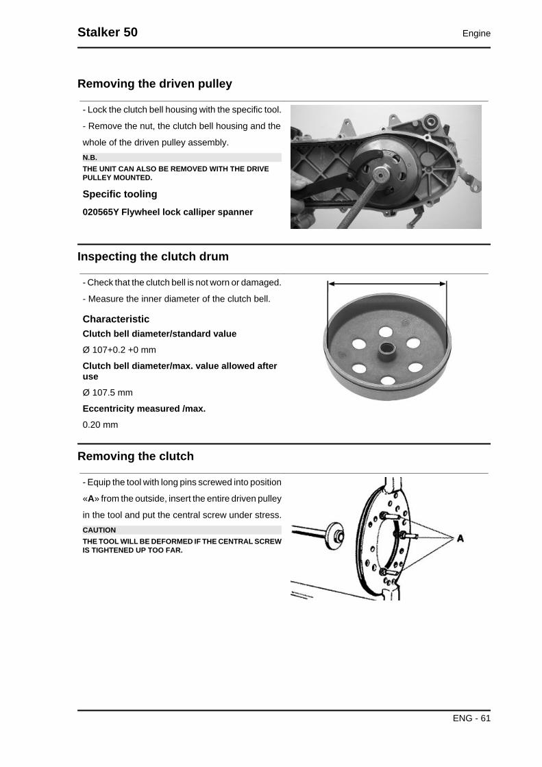
- Lock the clutch bell housing with the specific tool.
- Remove the nut, the clutch bell housing and the
whole of the driven pulley assembly.N.B.THE UNIT CAN ALSO BE REMOVED WITH THE DRIVEPULLEY MOUNTED.
Specific tooling020565Y Flywheel lock calliper spanner
Inspecting the clutch drum
- Check that the clutch bell is not worn or damaged.
- Measure the inner diameter of the clutch bell.
CharacteristicClutch bell diameter/standard valueØ 107+0.2 +0 mm
Clutch bell diameter/max. value allowed afteruseØ 107.5 mm
Eccentricity measured /max.0.20 mm
Removing the clutch
- Equip the tool with long pins screwed into position
«A» from the outside, insert the entire driven pulley
in the tool and put the central screw under stress.CAUTIONTHE TOOL WILL BE DEFORMED IF THE CENTRAL SCREWIS TIGHTENED UP TOO FAR.
Stalker 50 Engine
ENG - 61

- Using a 34 mm socket wrench remove the clutch
locking nut.
- Loosen the central screw thereby undoing the
driven pulley unit
- Separate the components.
Specific tooling020444Y Tool for fitting/ removing the drivenpulley clutch
Inspecting the clutch
- Check the thickness of the clutch mass friction
material.
- The masses must not show traces of lubricants;
otherwise, check the driven pulley unit seals.N.B.
UPON RUNNING-IN, THE MASSES MUST EX-HIBIT A CENTRAL CONTACT SURFACE ANDMUST NOT BE DIFFERENT FROM ONE AN-OTHER.VARIOUS CONDITIONS CAN CAUSE THECLUTCH TO TEAR.CAUTIONDO NOT OPEN THE MASSES USING TOOLS TO PREVENTA VARIATION IN THE RETURN SPRING LOAD.
CharacteristicCheck minimum thickness1 mm
Pin retaining collar
- Remove the collar with the aid of 2 screwdrivers.
Engine Stalker 50
ENG - 62

- Remove the three guide pins and the mobile half
pulley.
Removing the driven half-pulley bearing
- Remove the roller bearing with the special ex-
tractor inserted from the bottom of the fixed half-
pulley.CAUTIONPOSITION THE HOLDING EDGE OF THE EXTRACTION PLI-ERS BETWEEN THE END OF THE BEARING AND THEBUILT IN SEALING RING.
Specific tooling001467Y029 Bell for bearings, O.D. 38 mm
- Remove the ball bearing retention snap ring.
- Expel the ball bearing from the side of the clutch
housing by means of the special tool.N.B.PROPERLY SUPPORT THE HALF-PULLEY SO AS NOT TODEFORM THE SLIDING SURFACE OF THE DRIVING BELT
Specific tooling020376Y Adaptor handle
020363Y 20 mm guide
Inspecting the driven fixed half-pulley
- Check that there are no signs of wear on the work
surface of the belt. If there are, replace the half-
pulley..
- Make sure the bearings do not show signs of un-
usual wear.
- Measure the external diameter of the pulley bush-
ing.
Characteristic
Stalker 50 Engine
ENG - 63

Stationary driven half-pulley/Standard diame-terØ 33.965 to 33.985 mm
Stationary driven half-pulley / Minimum diam-eter admitted after useØ 33.96 mm
Inspecting the driven sliding half-pulley
- Remove the 2 inner sealing rings and the two O-
rings.
- Measure the inside diameter of the mobile half-
pulley bushing.
CharacteristicMobile driven half-pulley/ Maximum diameterallowedØ 34.08 mm
- Check the belt contact surfaces.
- Insert the new oil seal and O-rings on the mobile
half-pulley.
- Fitting the half-pulley on the bushing.
Recommended productsAGIP GREASE SM 2 Grease for the tone wheelrevolving ringSoap-based lithium grease containing NLGI 2 Mo-
lybdenum disulphide; ISO-L-XBCHB2, DIN
KF2K-20
- Make sure the pins and collar are not worn, reassemble the pins and collar.
- Use a greaser with a curved spout to lubricate the driven pulley unit with around 6 gr. of grease. This
operation must be done through one of the holes inside the bushing until grease comes out of the
opposite hole. This procedure is necessary to prevent the presence of grease beyond the O-ring.
Recommended productsAGIP GREASE SM 2 Grease for the tone wheel revolving ring
Soap-based lithium grease containing NLGI 2 Molybdenum disulphide; ISO-L-XBCHB2, DIN KF2K-20
Engine Stalker 50
ENG - 64
Refitting the driven half-pulley bearing
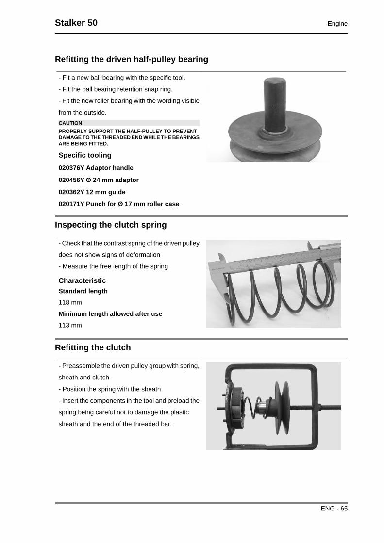
- Fit a new ball bearing with the specific tool.
- Fit the ball bearing retention snap ring.
- Fit the new roller bearing with the wording visible
from the outside.CAUTIONPROPERLY SUPPORT THE HALF-PULLEY TO PREVENTDAMAGE TO THE THREADED END WHILE THE BEARINGSARE BEING FITTED.
Specific tooling020376Y Adaptor handle
020456Y Ø 24 mm adaptor
020362Y 12 mm guide
020171Y Punch for Ø 17 mm roller case
Inspecting the clutch spring
- Check that the contrast spring of the driven pulley
does not show signs of deformation
- Measure the free length of the spring
CharacteristicStandard length118 mm
Minimum length allowed after use113 mm
Refitting the clutch
- Preassemble the driven pulley group with spring,
sheath and clutch.
- Position the spring with the sheath
- Insert the components in the tool and preload the
spring being careful not to damage the plastic
sheath and the end of the threaded bar.
Stalker 50 Engine
ENG - 65

- Reassemble the nut securing the clutch and tight-
en to the prescribed torque.CAUTIONSO AS NOT TO DAMAGE THE CLUTCH NUT USE A SOCK-ET WRENCH WITH SMALL CHAMFER.CAUTIONPOSITION THE NON-CHAMFERED SURFACES OF THENUT IN CONTACT WITH THE CLUTCH
Locking torques (N*m)Nut locking clutch unit on pulley 55 ÷ 60 Nm
Refitting the driven pulley
-Refit the driven pulley assembly, the clutch bell
and the nut, using the specific tool.
Specific tooling020565Y Flywheel lock calliper spanner
Locking torques (N*m)Driven pulley shaft nut 40 to 44 Nm
Drive-belt
- Make sure the driving belt is not damaged and
does not have cracks in the toothed grooves.
- Check the width of the belt.
CharacteristicTransmission belt/Minimum width17.5 mm
Engine Stalker 50
ENG - 66

Removing the driving pulley
- Lock the driving pulley using the appropriate tool.
- Remove the central nut with the related washer,
then remove the drive and the plastic fan.
- Remove the stationary half-pulley.
- Remove the belt, washer and remove the mobile half-pulley with its bushing, being careful that the
rollers and contrast plate fitted loosely on it do not come off.
Specific tooling020451Y Starting ring gear lock
Mixer gears and belt
- Remove gear and belt.CAUTIONPAY PARTICULAR ATTENTION TO NOT TOUCHING ORBENDING THE BELT BECAUSE THIS COULD BREAK SUD-DENLY DURING OPERATION.CAUTIONON REFITTING, MAKE SURE THAT DIRT DOES NOT GETINTO THE INNER BUSHING OF THE MIXER CONTROLGEAR AND THAT IT DOES NOT EXERT ANY STRESS ONTHE CRANKCASE PIN.N.B.REPLACE THE BELT EVERY 20000 KM.
Inspecting the rollers case
1) Check that the bushing and the sliding rings of
the mobile pulley do not show signs of scoring or
deformation.
2) Check the roller running tracks on the contact
pulley; there must not be signs of wear and check
the condition of the contact surface of the belt on
the half-pulleys (mobile and stationary).
3) Check that the rollers do not show signs of
marked facetting on the sliding surface and that
the metallic insert does not come out of the plastic
shell borders.
Stalker 50 Engine
ENG - 67

4) Check the integrity of the sliding blocks of the
contact plate.
- Check that the internal bushing shown in the fig-
ure is not abnormally worn and measure inside
diameter «A».
- Measure outside diameter «B» of the pulley slid-
ing bushing shown in the figure.CAUTIONDO NOT LUBRICATE OR CLEAN THE BUSHING.
CharacteristicDriving pulley / Maximum diameter:20.12 mm
Driving pulley/ Standard diameter:20.021 mm
Driving pulley bushing/ Diameter maximum:XXX mm
Driving pulley bushing/ Standard diameter:20 -0.020/-0.041mm
Refitting the driving pulley
- Manually move the movable driven half-pulley
away by pulling it towards the clutch unit and insert
the belt observing the direction of rotation of the
first fitting.N.B.IT IS GOOD PRACTICE ALWAYS TO FIT THE BELT SOTHAT THE WORDS CAN BE READ IN CASE IT DOES NOTSHOW A FITTING SIDE.
- Refit the components of the assembly (roller con-
tainer assembly with bushing, limiting washer, sta-
tionary half-pulley, cooling fan belt with drive,
washer and nut).
- With the specific tool, tighten the lock nut to 20
Nm and then perform a final 90° locking in order to
prevent the rotation of the driving pulley.N.B.REPLACE THE NUT WITH A NEW ONE AT EVERY REFITCAUTIONUPON FITTING THE DRIVING PULLEY UNIT IT IS OF UT-MOST IMPORTANCE THAT THE BELT IS FREE INSIDE IN
Engine Stalker 50
ENG - 68

ORDER TO AVOID WRONG TIGHTENING AND CONSE-QUENTLY DAMAGING THE CRANKSHAFT KNURLING.
Specific tooling020451Y Starting ring gear lock
Locking torques (N*m)Crankshaft pulley nut 18 to 20 + 90° Nm
End gear
Removing the hub cover
• Remove the transmission cover
• Remove the clutch assembly
• Discharge the rear hub oil.
• Remove the 5 screws indicated in the figure.
• Remove the hub cover with driven pulley shaft.
See alsoRefitting the clutch
Removing the wheel axle
- Remove the intermediate gear and the complete
gear wheel axle.
- When removing the intermediate gear pay atten-
tion to the various shim adjustments.
Stalker 50 Engine
ENG - 69

Removing the wheel axle bearings
- Remove the oil seal and the seeger ring.
- Remove the bearing by pushing from the outside
towards the inside of the gear compartment, using
the appropriate punch.
Specific tooling020363Y 20 mm guide
020376Y Adaptor handle
020358Y 37x40-mm adaptor
Removing the driven pulley shaft bearing
- Remove the seeger ring inside the cover.
- Remove the oil seal from the outside.
- Remove the centring dowels and position the
cover on a plane.
- Position the special tool on the internal track of
the bearing and remove said bearing with the aid
of a press.
Specific tooling020452Y Tube for removing and refitting thedriven pulley shaft
- Position the special tube on the internal raceway
of the bearing and from the shaft toothed side as
indicated in the figure. Expel the driven pulley shaft
with the aid of a press.
Specific tooling020452Y Tube for removing and refitting thedriven pulley shaft
Engine Stalker 50
ENG - 70
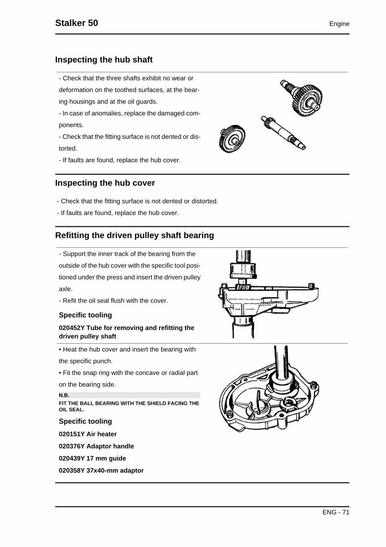
Inspecting the hub shaft
- Check that the three shafts exhibit no wear or
deformation on the toothed surfaces, at the bear-
ing housings and at the oil guards.
- In case of anomalies, replace the damaged com-
ponents.
- Check that the fitting surface is not dented or dis-
torted.
- If faults are found, replace the hub cover.
Inspecting the hub cover
- Check that the fitting surface is not dented or distorted.
- If faults are found, replace the hub cover.
Refitting the driven pulley shaft bearing
- Support the inner track of the bearing from the
outside of the hub cover with the specific tool posi-
tioned under the press and insert the driven pulley
axle.
- Refit the oil seal flush with the cover.
Specific tooling020452Y Tube for removing and refitting thedriven pulley shaft
• Heat the hub cover and insert the bearing with
the specific punch.
• Fit the snap ring with the concave or radial part
on the bearing side.N.B.FIT THE BALL BEARING WITH THE SHIELD FACING THEOIL SEAL.
Specific tooling020151Y Air heater
020376Y Adaptor handle
020439Y 17 mm guide
020358Y 37x40-mm adaptor
Stalker 50 Engine
ENG - 71

Refitting the wheel axle bearing
- Heat the half crankcase on the transmission side
using a thermal gun.
- After lubricating its outer strip, insert the bearing
with the special adapter with the aid of a hammer.
- Refit the seeger ring and the oil seal using the 42
x 47 mm adapter and the handle.
Specific tooling020151Y Air heater
020376Y Adaptor handle
020363Y 20 mm guide
020359Y 42x47-mm adaptor
Refitting the ub cover
- Refit the whole wheel axle.
- Refit the intermediate gear paying attention to the
two shim thicknesses.
- Apply LOCTITE 510 for surfaces to the hub cov-
ers and refit the same with driven pulley shaft.
- Refit the 5 screws and tighten them to the speci-
fied torque.N.B.CLEAN THE CONTACT SURFACES OF THE HUB COVERAND THE HALF CRANKCASE OF RESIDUE FROM PREVI-OUS GASKETS BEFORE APPLYING A NEW ONE.
Locking torques (N*m)Locking torque: 11 to 13 Nm
Flywheel cover
Engine Stalker 50
ENG - 72

Cooling hood
- Remove the four fixings shown in the figure.
- Remove the fan cover
- Remove the oil piping retention band from the
hood
- Remove the 2 screws shown in the figure
Cooling fan
- Remove the cooling fan by acting on the three
fixings indicated in the figure.
Stalker 50 Engine
ENG - 73

Removing the stator
- Remove the three stator fixings shown in the
photo
- Remove the two pick-up fixings shown in the
photo
- Remove the stator with the wiring
Refitting the stator
- Refit the stator and flywheel carrying out the removal procedure in reverse, tightening the retainers to
the specified torque.N.B.
THE PICK-UP CABLE MUST BE POSITIONED ADHERING TO THE FUSION TONGUE ON THECRANKSHAFT IN SUCH A WAY AS TO AVOID BEING CRUSHED BY THE FAN COVER ASSEM-BLY.
Locking torques (N*m)Pick-up screws 3 ÷ 4 Stator screws 3 ÷ 4
Flywheel and starting
Removing the starter motor
• Remove the center stand by unscrew-
ing the four clamping screws (two per
side) of the engine block
• R
emove the two clamps shown in the figure
Engine Stalker 50
ENG - 74

Removing the flywheel magneto
- Lock the rotation of the flywheel using the calliper
spanner.
- Remove the nut.CAUTIONTHE USE OF A CALLIPER SPANNER OTHER THAN THEONE SUPPLIED COULD DAMAGE THE STATOR COILS
- Extract the flywheel with the extractor.
Specific tooling020565Y Flywheel lock calliper spanner
020162Y Flywheel extractor
Inspecting the flywheel components
- Check the condition of the flywheel and any dis-
tortions that might cause rubbing on the stator and
on the Pick-Up.
Stalker 50 Engine
ENG - 75

Refitting the flywheel magneto
- Fit the flywheel being careful to insert the key
properly.
- Lock the flywheel nut at the prescribed torque
- Check the Pick-Up air gap.
- The air gap may not be modified in the fitting of
the Pick-Up.
- Other values derive from deformations visible on
the Pick-Up support.N.B.A VARIATION OF THE AIR GAP DISTANCE CAN LEAD TOA VARIATION IN THE IGNITION ADVANCE SUCH AS TOCAUSE PINGING, KNOCKING ETC.
Locking torques (N*m)Flywheel nut 40 to 44 N.m
Refitting the starter motor
- Fit a new O-ring on the starter and lubricate it.
- Fit the starter on the crankcase, locking the two
screws to the prescribed torque.N.B.REFIT THE REMAINING PARTS AS DESCRIBED IN THECYLINDER HEAD, TIMING, LUBRICATION, FLYWHEELAND TRANSMISSION CHAPTERS.
Locking torques (N*m)Starter motor screws 11 ÷ 13
Cylinder assy. and timing system
Removing the intake manifold
Use an anti-tampering TORX spanner to remove
the two clamping screws of the intake manifold
Engine Stalker 50
ENG - 76

Removing the cylinder head
Remove the 4 screws shown in the figure
Removing the cylinder - piston assy.
Remove the cylinder very carefully
Remove the snap rings and remove the pinCAUTIONAFTER EACH REMOVAL OPERATION REPLACE THE PINRETENTION SNAP RINGS
Stalker 50 Engine
ENG - 77

Inspecting the small end
- Measure the internal diameter of the small end
using an internal micrometer.N.B.IF THE DIAMETER OF THE ROD SMALL END EXCEEDSTHE MAXIMUM DIAMETER ALLOWED, SHOWS SIGNS OFWEAR OR OVERHEATING REPLACE THE CRANKSHAFTAS DESCRIBED IN THE "CRANKCASE AND CRANK-SHAFT" CHAPTER".
CharacteristicRod small end: standard diameter17 +0.011-0.001
Rod small end: maximum allowable diameter17,060 mm
Inspecting the wrist pin
- Check the wrist pin external diameter using a mi-
crometer
CharacteristicWrist pin: standard diameter12 +0.005 +0.001 mm
Inspecting the piston
- Measure the bearings on the piston using a bore
meter
- Calculate the piston-pin coupling clearance.
CharacteristicWrist pin housing: standard diameter12 +0.007 +0.012
Wrist pin housing: standard clearance0.002 ÷ 0.011 mm
Engine Stalker 50
ENG - 78
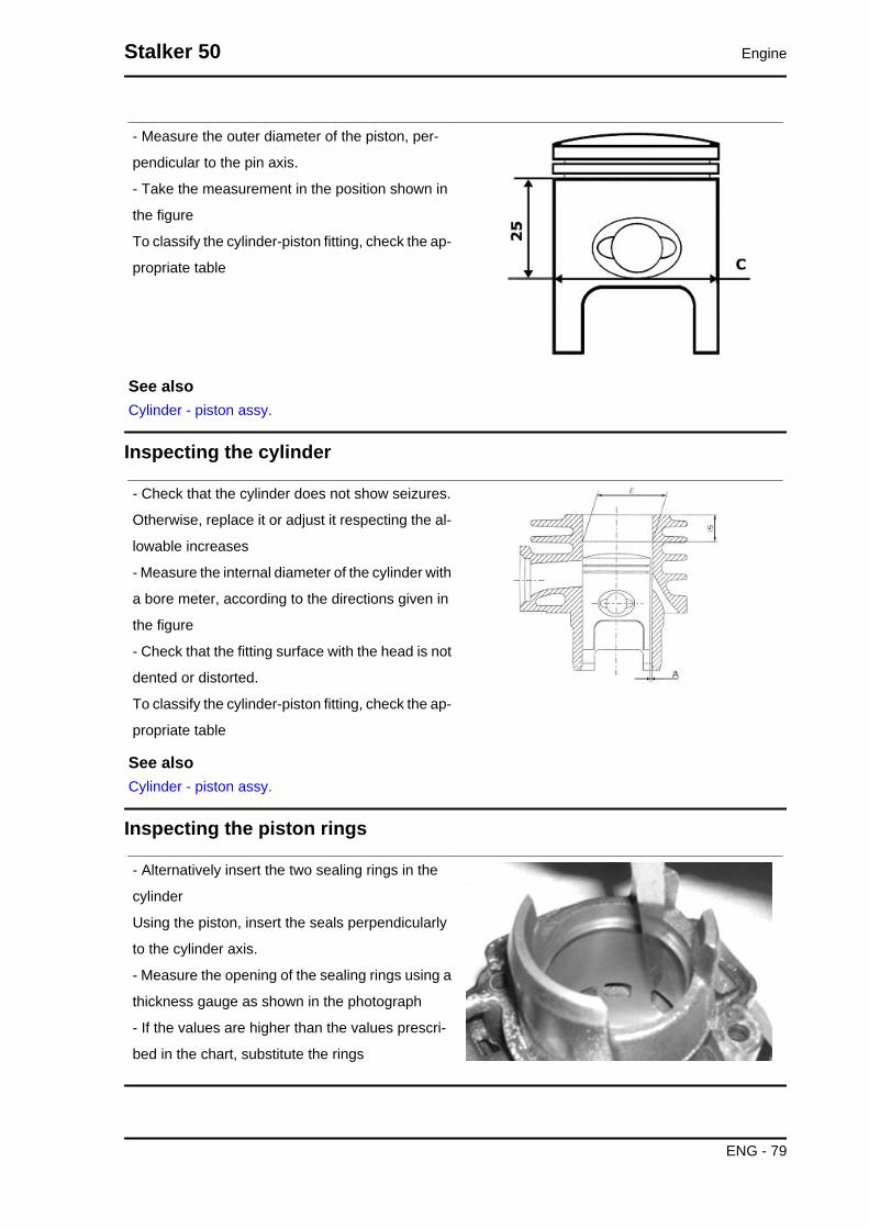
- Measure the outer diameter of the piston, per-
pendicular to the pin axis.
- Take the measurement in the position shown in
the figure
To classify the cylinder-piston fitting, check the ap-
propriate table
See alsoCylinder - piston assy.
Inspecting the cylinder
- Check that the cylinder does not show seizures.
Otherwise, replace it or adjust it respecting the al-
lowable increases
- Measure the internal diameter of the cylinder with
a bore meter, according to the directions given in
the figure
- Check that the fitting surface with the head is not
dented or distorted.
To classify the cylinder-piston fitting, check the ap-
propriate table
See alsoCylinder - piston assy.
Inspecting the piston rings
- Alternatively insert the two sealing rings in the
cylinder
Using the piston, insert the seals perpendicularly
to the cylinder axis.
- Measure the opening of the sealing rings using a
thickness gauge as shown in the photograph
- If the values are higher than the values prescri-
bed in the chart, substitute the rings
Stalker 50 Engine
ENG - 79

Removing the piston
- Position the snap ring in detail 1 with the opening straddling the arrow printed on the tool.
-Push detail 2 into detail 1 until the stop and extract detail 2.
- Insert detail 3 into detail 1, position the assembly in the snap ring assembly area, and push detail 3
all the way in.N.B.
REFIT THE REMAINING PARTS FOLLOWING THE OPERATIONS IN REVERSE ORDER FROMTHE REMOVAL OPERATIONS
Specific tooling020166Y Pin lock fitting tool
Locking torques (N*m)Locking head nuts: 10 to 11 N·m
- Use new wrist pin snap rings.
- Use new cylinder base gasket.
- Before refitting carefully clean all the surfaces.
- Use oil to be mixed during the fitting of the piston
and the cylinder.CAUTION
POSITION THE ARROW PRINTED ON THE PIS-TON CROWN TOWARDS THE EXHAUSTOPENING.THE WRIST PIN SNAP RINGS MUST BE POSI-TIONED ON THE PISTON WITH THE SPECIFICTOOL
Recommended productsAGIP CITY TEC 2T OilRecommended oil
Engine Stalker 50
ENG - 80

Inspecting the timing system componentsCAUTIONCHECK THE CORRECT REED UNIT SEAL; NO LIGHTMUST PASS BETWEEN THE SUPPORT AND LAMELLA.
Crankcase - crankshaft
Splitting the crankcase halves
Remove the eight crankcase union fasteners.
Stalker 50 Engine
ENG - 81

Install the special strip on the half crankcase on
the flywheel side and separate the half crankcase
on the flywheel side from the transmission side
Specific tooling020163Y Crankcase splitting plate
Removing the crankshaft
- Install the specific tool on the half crankcase on
the transmission side using four M6 screws of an
adequate length.
- Remove the crankshaft from the transmission
side half crankcase
Specific tooling020163Y Crankcase splitting plate
Removing the crankshaft bearings
The bearings can stay on either the half crankcase
or the crankshaft indifferently
- Using the special tool, remove any bearings that
have been left on the crankshaftN.B.The half rings must be inserted on the bearings with a few mal-let blows.
Specific tooling004499Y001 Bearing extractor bell
004499Y006 Bearing extractor ring
004499Y002 Bearing extractor screw
004499Y007 Half rings
Engine Stalker 50
ENG - 82

- Using the specific tool remove any bearings left
on the half crankcase
Specific tooling001467Y007 Driver for OD 54 mm bearing
001467Y006 Pliers to extract 20 mm bearings
Refitting the crankshaft bearings
Heat the bearings in an oil bath at around 150°C
and fit them on the crankshaft, if necessary using
a section of tube that acts on the bearing's inner
track
Specific tooling020265Y Bearing fitting base
Inspecting the crankshaft alignment
With the specific tool shown check that the eccen-
tricity of the surfaces of diam. «A»-«B»-« C» are
within 0.03 mm. (reading limit on the dial gauge);
in addition, check the eccentricity of diam. «D», for
which a maximum reading of 0.02 mm is permitted.
In the case where eccentricity is not much above
prescribed levels, straighten the shaft by acting
on the counterweights with a shim or tighten them
in a clamp (with an aluminium bushing) as re-
quired..
Specific tooling020335Y Magnetic support for dial gauge
020074Y Support base for checking crankshaftalignment
Stalker 50 Engine
ENG - 83

Refitting the crankshaft
- Position the transmission side half crankcase on
two wooden supports
- Using a thermal gun, heat the bearing seat to
about 120°
- Firmly insert the crankshaft until the bearing rea-
ches the end-of-stroke stop
- Let the temperature of the half crankcase settle
at the temperature of the crankshaft.
- Again install the special crankcase separation
plate NOT installing the crankshaft protection
- During the assembly phase keep the central
thrust screw loose.
- Take the four clamping screws to the end of the
stroke and loosen them again with the same angle
(e.g. 90°)
- When the temperature has settled, preload the
thrust screw of the tool manually until the ball bear-
ing clearance is cancelled out.
Specific tooling020163Y Crankcase splitting plate
Engine Stalker 50
ENG - 84

Refitting the crankcase halves
- Prepare the coupling surface with LOCTITE 510
applying a thin layer of it after degreasing the sur-
face using a suitable solvent (e.g. trichloroethy-
lene)
- Heat the flywheel-side half crankcase with a ther-
mal gun.
Recommended productsLoctite 510 Liquid sealantGasket
- Keeping the half crankcase on the transmission
side, insert the flywheel side half crankcase with a
clean precise movement
- Insert at least three clamping screws and tighten
up rapidly
- Insert the other 5 screws and tighten them to the
specified torque.
Locking torques (N*m)crankcase coupling screws 11 - 13
- Move the crankcase separation plate in a position
back from the one indicated in the figure
- Install the special magnetic support with dial
gauge at the end of the crankshaft
- Check the axial clearance of the crankcase
If this is not within the maximum limit allowed, re-
peat the crankcase coupling procedure
Specific tooling020335Y Magnetic support for dial gauge
CharacteristicAxial clearance with warm crankcase0.10 ÷ 0.12 mm
Axial clearance with cold crankcase0.06 to 0.08 mm
Limit value with cold crankcase0.02 ÷ 0.03 mm
Stalker 50 Engine
ENG - 85

Lubrication
Crankshaft oil seals
Refitting
- Install a new flywheel-side oil seal only with the
special tool's punch
The flywheel-side oil seal is recognised by its
smaller diameterN.B.
THE USE OF THE SPECIFIC TOOL IS NOTCOMPATIBLE WITH THE FITTED WRENCH
Specific tooling020340Y Flywheel and transmission oil sealsfitting punch
- Install a new transmission side oil seal using the
special tool with adapter ring.
The transmission-side oil seal is recognised by the
larger diameter
Specific tooling020340Y Flywheel and transmission oil sealsfitting punch
Oil pump
Removal
- Remove the 2 screws shown in the figure
Engine Stalker 50
ENG - 86
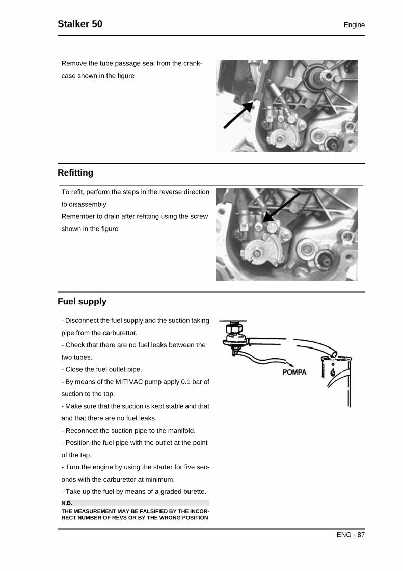
Remove the tube passage seal from the crank-
case shown in the figure
Refitting
To refit, perform the steps in the reverse direction
to disassembly
Remember to drain after refitting using the screw
shown in the figure
Fuel supply
- Disconnect the fuel supply and the suction taking
pipe from the carburettor.
- Check that there are no fuel leaks between the
two tubes.
- Close the fuel outlet pipe.
- By means of the MITIVAC pump apply 0.1 bar of
suction to the tap.
- Make sure that the suction is kept stable and that
and that there are no fuel leaks.
- Reconnect the suction pipe to the manifold.
- Position the fuel pipe with the outlet at the point
of the tap.
- Turn the engine by using the starter for five sec-
onds with the carburettor at minimum.
- Take up the fuel by means of a graded burette.N.B.THE MEASUREMENT MAY BE FALSIFIED BY THE INCOR-RECT NUMBER OF REVS OR BY THE WRONG POSITION
Stalker 50 Engine
ENG - 87

OF THE TUBE.. IN THIS CASE, THE TENDENCY IS TO OB-TAIN A REDUCED FUEL FLOW RATE. THE SUCTION OUT-LET ON THE MANIFOLD HAS A SECTION INTENTIONALLYREDUCED FOR THE PURPOSE OF ENHANCING THE SUC-TION PULSATION AND THEREBY GUARANTEE A CON-STANT TAP FLOW RATE.
Specific tooling020329Y MityVac vacuum-operated pump
CharacteristicMinimum flow rate20 cc
- Completely empty the gas tank.
- Remove the petrol delivery tube and the suction
tube.
- Loosen the clip and remove the tap.
- Clean the tank and the filter of the tap with a spe-
cific solvent.
- Refit the tap making sure that there is an O-Ring.
- Turn the tap to the direction it had before it was
removed and block the clip.N.B.THE FILTER CAN BE UNSCREWED FROM THE COCK TOFACILITATE CLEANING.
Engine Stalker 50
ENG - 88

INDEX OF TOPICS
SUSPENSIONS SUSP

Front suspension
This section is devoted to operations that can be carried out on the suspension.
Front
Removing the front wheel
- Support the vehicle in such a way that the front
wheel is raised.
- Using two 18 mm hexagonal wrenches remove
the front wheel axle.
Refitting the front wheel
- When refitting, pay attention in repositioning the
odometer drive correctly.
Locking torques (N*m)Wheel fixing nut 40 to 50 N.m
Handlebar
Suspensions Stalker 50
SUSP - 90
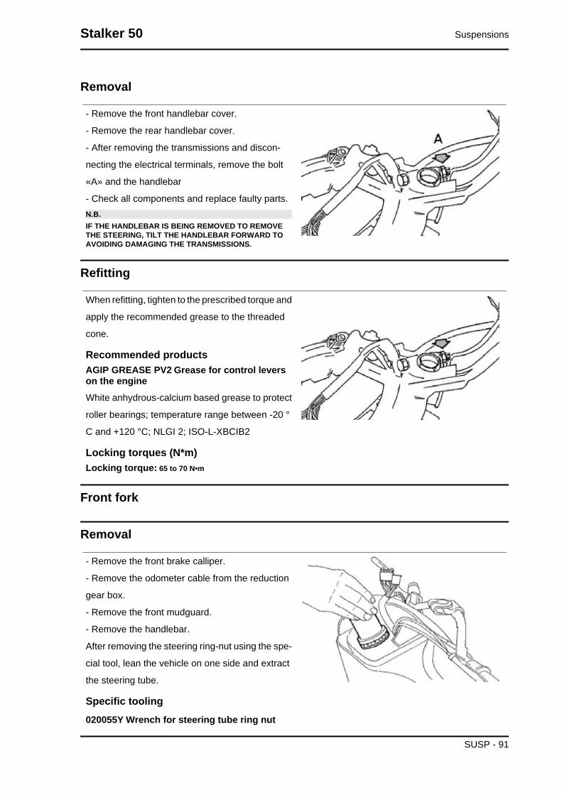
Removal
- Remove the front handlebar cover.
- Remove the rear handlebar cover.
- After removing the transmissions and discon-
necting the electrical terminals, remove the bolt
«A» and the handlebar
- Check all components and replace faulty parts.N.B.IF THE HANDLEBAR IS BEING REMOVED TO REMOVETHE STEERING, TILT THE HANDLEBAR FORWARD TOAVOIDING DAMAGING THE TRANSMISSIONS.
Refitting
When refitting, tighten to the prescribed torque and
apply the recommended grease to the threaded
cone.
Recommended productsAGIP GREASE PV2 Grease for control leverson the engineWhite anhydrous-calcium based grease to protect
roller bearings; temperature range between -20 °
C and +120 °C; NLGI 2; ISO-L-XBCIB2
Locking torques (N*m)Locking torque: 65 to 70 N•m
Front fork
Removal
- Remove the front brake calliper.
- Remove the odometer cable from the reduction
gear box.
- Remove the front mudguard.
- Remove the handlebar.
After removing the steering ring-nut using the spe-
cial tool, lean the vehicle on one side and extract
the steering tube.
Specific tooling020055Y Wrench for steering tube ring nut
Stalker 50 Suspensions
SUSP - 91

See alsoFrontbrake calliperHandlebar
OverhaulStem removal
- Remove the dust guard (1) using a screwdriver
to prise it out.
- Remove the seeger (2) and remove the power
pipe.N.B.GREASE THE SPRINGS AND THE BUSHINGS BEFOREREFITTING, WITH A SMALL QUANTITY OF GREASE(AROUND 3 GR.)
Recommended productsAGIP GREASE MU3 Grease for odometertransmission gear caseSoap-based lithium grease with NLGI 3; ISO-L-
XBCHA3, DIN K3K-20
Removing damper
- Remove screw 1 fixing the screw to the stem and
remove the stanchion heating it if necessary with
the specified heater, then remove sealing ring 2
and seeger 3.
- Using nut 4, remove the spring stem and bushing.
The damper is an integral part of the stem and
cannot therefore be overhauled, so if you need to
work on the damper (loss of fork oil), carry out the
operations mentioned above and replace the
shock absorber-stem unit.
When refitting, tighten to the prescribed torque and
apply the recommended grease to the threadlock
nut.
Specific tooling020150Y Air heater support
020151Y Air heater
Recommended products
Suspensions Stalker 50
SUSP - 92

Loctite 243 Medium strength threadlockLoctite 243 medium-strength threadlock
Locking torques (N*m)Stud-stanchion fixing screw 20 to 25 N•m Nuttightening torque 20 to 25 N•m
Replacing sealing ring
- Remove the wheel axle.
- Remove the screw (4).
- Remove the stanchion (3).
- Remove the dust guard (1).
- Insert the new sealing ring after lubricating the
inside parts of the ring and paying attention not to
damage it.
- Insert the stanchion appIying the recommended
product to the clean surface.
- Lock the screw (4).
Recommended productsLoctite 243 Medium strength threadlockLoctite 243 medium-strength threadlock
Refitting
Lubricate the seats and the balls with the grease
recommended.
- Lock at the prescribed torque and turn the key
anticlockwise by 90° to 100°.
Specific tooling020055Y Wrench for steering tube ring nut
Recommended productsAGIP GREASE PV2 Grease for control leverson the engineWhite anhydrous-calcium based grease to protect
roller bearings; temperature range between -20 °
C and +120 °C; NLGI 2; ISO-L-XBCIB2
Locking torques (N*m)Locking torque: 50 to 60 Nm
Stalker 50 Suspensions
SUSP - 93

Steering column
RemovalRemoval of the upper and lower frame seat
- Only remove the seats if it is strictly necessary.
- Using the special tool remove the upper fifth
wheel seat by putting the special tool into the lower
part of the headstock as indicated in the figure.
- By inserting the punch into the top of the tube,
remove the lower fifth wheel seat from the head-
stock.
Specific tooling020004Y Punch for removing fifth wheels fromheadstock
RefittingRefitting the lower and upper seat on the frame
- Using the special tool, refit the upper and lower
bearing seats on the headstock.
Specific tooling001330Y Tool for fitting steering seats
Steering bearing
RemovalOverhauling the fifth wheel seat on the fork
Suspensions Stalker 50
SUSP - 94

Check the condition of the fifth wheel and the fifth
wheel seat on the fork (steering tube). Replace if
there are faults.
- Support the fork properly.
- Using the special tool, remove the fifth wheel seat
on the steering tube as shown in the photograph
by applying small mallet blows.
Specific tooling020004Y Punch for removing fifth wheels fromheadstock
Always use a new fifth wheel seat on refitting.
- Using the special tool, refit the fifth wheel seat
with the aid of a few mallet blows and bring it as
far as the stop shown in the photo.
Specific tooling006029Y Punch for fitting fifth wheel seat onsteering tube
Removing steering lock nut
- Remove the handlebar.
- Remove the bearing of steering ring nut using the
specific tool.
Specific tooling020055Y Wrench for steering tube ring nut
See alsoHandlebar
RefittingRefitting steering lock ring nut
- After locking the first ring nut in place, lock the
second ring nut using a specific tool.
Specific tooling
Stalker 50 Suspensions
SUSP - 95

020055Y Wrench for steering tube ring nut
Locking torques (N*m)Locking torque: 30 to 40 Nm
Rear
Removing the rear wheel
- Use a screwdriver as a lever between the drum
and the cover.
-Straighten the split pin and remove the cap.
-Remove the wheel acting on the central fixing
point.WARNING-ALWAYS USE NEW SPLIT PINS FOR REFITTING.
Removal
To replace the shock absorber you just need to
remove the battery access flap to get and remove
the shock absorber/ frame anchorage nut. Then
remove the shock absorber/engine anchorage
nut.
Refitting
When refitting, tighten the shock absorber/frame anchorage nut and the shock absorber/engine pin at
the prescribed torque.
Suspensions Stalker 50
SUSP - 96

Locking torques (N*m)Shock absorber/frame nut torque 20 to 25 Nm Shock absorber/engine pin torque 33 to 41 N·m
Centre-standExpulsion of stand fastening pin to the bracket
- Remove the stand support bracket from the en-
gine.
- Drill a 5 mm hole in the bracket so that the pin
«P» can come out.
Fitting and caulking the stand pin to the bracket
- Caulk the end of the pin «P» between the two
punches shown in the figure.
- After caulking it must be possible for the stand to
turn freely.N.B.UPON REFITTING USE NEW O-RING AND PIN, GREASETHE SPRING ATTACHMENTS AND THE PIN.
Replace complete stand
- Work on the screws shown in the figure.
- When refitting, secure to the prescribed torque.
Locking torques (N*m)Stand screw torque 18.5 to 19 Nm
Stalker 50 Suspensions
SUSP - 97

INDEX OF TOPICS
BRAKING SYSTEM BRAK SYS

Front brake calliper
Removal
• Check that the brake piping, gasket
and fitting are in good condition. If you
see any oil on the brake calliper and/on
the components of the system, it is
necessary to replace them.
• - Disconnect the oil line from the cal-
liper, collecting the oil in a container.
• - Remove the two clamps highlighted
in the diagram.
Overhaul
• Disconnect the oil line from the calliper
and collect the brake fluid in a suitable
container.
• Remove the brake calliper from the
fork.
• Exerting leverage on the floating body,
remove the external brake pad, then
the internal one, and lastly the reten-
tion spring.
• Remove the piston and make sure that
there is no scoring or erosion. If there
is, replace the pincer.CAUTION
ALL THE INTERNAL COMPONENTS MUST BEREPLACED EVERY TIME THE CALLIPER ISSERVICED.
Stalker 50 Braking system
BRAK SYS - 99

• Insert the sealing rings and the pistons
in the calliper body
• Check the state of the floating body
seats and grease them.
• Refit the pads
• - Position the calliper on the disc and
lock to the mounting by tightening the
bolts.
• Lock the piping fitting on the calliper at
the prescribed torque and bleed the air
from the system.
Before fitting, the parts must be perfectly clean and
free of traces of oil, diesel fuel, grease, etc..
They should be washed thoroughly in denatured
alcohol before proceeding.
The sealing rings must be immersed in the op-
erating liquid; the use of the PRF1 protection is
tolerated.CAUTION
RUBBER PARTS SHOULD NEVER BE LEFT INALCOHOL FOR LONGER THAN 20 SECONDS.AFTER WASHING, THE PIECES MUST BEDRIED WITH A BLAST OF COMPRESSED AIRAND A CLEAN CLOTH.
Locking torques (N*m)Calliper coupling screw 20 to 25 Nm Oil bleedscrew 7 to 10 Nm
Refitting
• Refit the pincer on the support and
tighten the screws at the prescribed
torque.
• Refit the tube complete with fitting with
new copper gaskets.
• Bleed the air from the system.
Locking torques (N*m)Brake fluid tube calliper 20 ÷ 25 Nm Fasteningscrews calliper to the crankcase 20 - 25 Oil bleedscrew 7 to 10 Nm
Braking system Stalker 50
BRAK SYS - 100

Front brake disc
Removal
Proceed as follows:
- Remove the front wheel
- Undo the three disc clamping screws.
Refitting
-When refitting, position the disc correctly making sure that it rotates in the right direction.
Locking torques (N*m)Disc tightening screw 8 - 12
Disc Inspection
• Use the micrometer to check the thick-
ness of the disc as shown in the pho-
tograph
CharacteristicStandard thickness:4 +02-01mm
• Using the appropriate tool, measure
how much the disc protrudes when the
wheel is fitted properly. The protrusion,
measured near the external edge of
the disc, must be less than 0.1 mm.
• If a value is measured other than the
specified value, remove the front wheel
(Front/Rear Suspension chapter) and
check the protrusion of the disc. Maxi-
mum permissible out of true is 0.1 mm.
Stalker 50 Braking system
BRAK SYS - 101
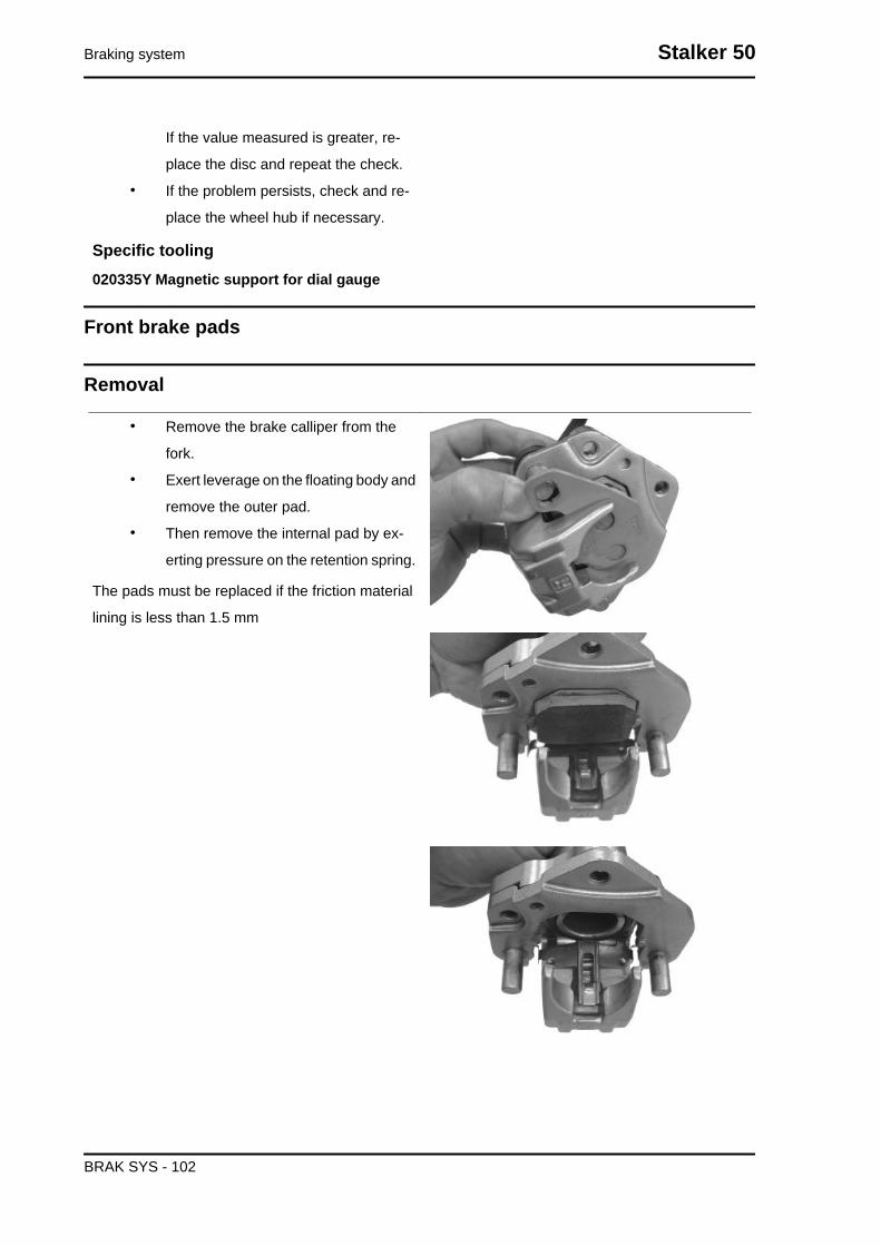
If the value measured is greater, re-
place the disc and repeat the check.
• If the problem persists, check and re-
place the wheel hub if necessary.
Specific tooling020335Y Magnetic support for dial gauge
Front brake pads
Removal
• Remove the brake calliper from the
fork.
• Exert leverage on the floating body and
remove the outer pad.
• Then remove the internal pad by ex-
erting pressure on the retention spring.
The pads must be replaced if the friction material
lining is less than 1.5 mm
Braking system Stalker 50
BRAK SYS - 102

Refitting
Follow the steps in the opposite order from the re-
moval, making sure the retention spring is inserted
properly.
Fill
Stalker 50 Braking system
BRAK SYS - 103

Front
-Once the bleed valve is closed, fill the system with
brake liquid to the maximum level.
-Undo the bleed screw.
-Apply the tube of the special tool to the bleed
screws.
When bleeding it is necessary to fill the oil tank in
continuation while working with a MITYVAC pump
on the bleed screws until no more air comes out of
the system.
The operation is finished when just oil comes out
of the bleed screws.
-Do up the bleed screw.
-When the operation is over, tighten up the oil
bleed screw to the prescribed torque.N.B.
IF AIR CONTINUES TO COME OUT DURINGPURGING, EXAMINE ALL THE FITTINGS:IF SAID FITTINGS DO NOT SHOW SIGNS OFBEING FAULTY, LOOK FOR THE AIR INPUTAMONG THE VARIOUS SEALS ON THE PUMPAND CALLIPER PISTONS.CAUTION- DURING THE OPERATIONS, THE VEHICLE MUST BE ONTHE STAND AND LEVEL.N.B.DURING PURGING FREQUENTLY CHECK THE LEVEL TOPREVENT AIR GETTING INTO THE SYSTEM THROUGHTHE PUMP.WARNING
- BRAKING CIRCUIT FLUID IS HYGROSCOPIC.IT ABSORBS HUMIDITY FROM THE SUR-ROUNDING AIR.IF THE LEVEL OF HUMIDITY IN THE BRAKINGFLUID EXCEEDS A GIVEN VALUE, BRAKINGEFFICIENCY WILL BE REDUCED.THEREFORE, ALWAYS USE FLUID FROMSEALED CONTAINERS.UNDER NORMAL DRIVING AND CLIMATICCONDITIONS YOU SHOULD CHANGE THISLIQUID EVERY TWO YEARS.IF THE BRAKES ARE USED INTENSELY AND/OR IN HARSH CONDITIONS, CHANGE THEFLUID MORE FREQUENTLY.CAUTIONWHEN CARRYING OUT THE OPERATION, BRAKE FLUIDMAY LEAK FROM BETWEEN THE BLEED SCREW AND ITSSEAT ON THE CALLIPER.
Braking system Stalker 50
BRAK SYS - 104
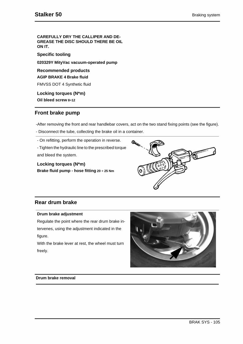
CAREFULLY DRY THE CALLIPER AND DE-GREASE THE DISC SHOULD THERE BE OILON IT.
Specific tooling020329Y MityVac vacuum-operated pump
Recommended productsAGIP BRAKE 4 Brake fluidFMVSS DOT 4 Synthetic fluid
Locking torques (N*m)Oil bleed screw 8÷12
Front brake pump
-After removing the front and rear handlebar covers, act on the two stand fixing points (see the figure).
- Disconnect the tube, collecting the brake oil in a container.
- On refitting, perform the operation in reverse.
- Tighten the hydraulic line to the prescribed torque
and bleed the system.
Locking torques (N*m)Brake fluid pump - hose fitting 20 ÷ 25 Nm
Rear drum brake
Drum brake adjustment
Regulate the point where the rear drum brake in-
tervenes, using the adjustment indicated in the
figure.
With the brake lever at rest, the wheel must turn
freely.
Drum brake removal
Stalker 50 Braking system
BRAK SYS - 105

After removing the muffler and the rear wheel do
the following:
1. Remove the shoe spring with the special tool
2. Remove the shoe with the aid of a lever
3. Refit the new shoes giving a few taps with
the mallet
4. Fasten the spring using the special tool.
Braking system Stalker 50
BRAK SYS - 106

INDEX OF TOPICS
CHASSIS CHAS

Rear handlebar cover
• Remove the front handlebar cover.
• - Remove the four screws indicated in
the figure.
• Disconnect the connections to the
switches.
For installation, reverse the removal sequence.
Instrument panel
- Remove the three screws indicated in the figure.
- Disconnect the joint of the odometer cable.
- Disconnect the two electrical connections.
Front handlebar cover
• Remove the instrument panel.
• - Remove the four screws indicated in
the figure.
• Prise upwards at the lateral fittings and
separate the front cover from the rear
cover.
• Disconnect the cable harness of the tail
light.
For installation, reverse the removal sequence,
paying attention to the correct assembly of the fit-
tings.
Chassis Stalker 50
CHAS - 108

Headlight assy.
• - Remove the front shield.
• Turn the two screws indicated in the
figure to remove the headlight assem-
bly.
During assembly, pay attention to the correct con-
nection of the cables to the lamp support.
LEGEND:
Bl= black
Vi= violet
Br= brown
Frame central cover
• Remove the 3 fixing screws located
under the saddle as shown in the fig-
ure.
• Remove the cover by pulling it off the
lower fittings.
For installation, reverse the removal sequence.
Stalker 50 Chassis
CHAS - 109

Legshield
- Remove the shield back plate
- Remove the four screws from the front wheel
housing.
- Remove the three screws from the front shield.
- Pull the shield from its seat and disconnect the
turn indicators and front headlight connectors.
For installation, reverse the removal sequence,
paying attention to the correct assembly of the
lower fittings.
During assembly, pay attention to the correct con-
nection of the cables to the lamp support.
LEGEND:
Bl= black
Vi= violet
Br= brown
Chassis Stalker 50
CHAS - 110

Knee-guard
- Remove the central chassis cover.
- Remove the footrest.
- Remove the eight screws shown in the figure
(four on each side).
- Remove the luggage rack hook by turning the two
screws.
- Pull the shield back plate down.
For installation, reverse the removal sequence,
paying attention to the correct assembly of the
lower fittings.
Taillight assy.
To replace the bulbs it is sufficient to remove the
two screws shown in the figure and to then pull off
the glass of the rear headlight.
During assembly, pay attention to correctly install
the glass of the turn indicators.
Stalker 50 Chassis
CHAS - 111

Footrest
• Remove the central chassis cover.
• Remove the 6 screws indicated in the
figure and remove the footrest by pri-
sing at the fittings.
Side fairings
• Remove the rear spoiler by loosening
the 4 retaining screws.
• Remove the central chassis cover.
• Remove the 8 retaining screws (4 each
side) indicated in the figure.
Chassis Stalker 50
CHAS - 112

Rear mudguard
• Remove the side panels
• Remove the 3 screws indicated in the
figure.
• Disconnect the electrical connection of
the tail light assembly and then pull off
the mudguard.
During assembly, position the connectors in the
correct housings.
Stalker 50 Chassis
CHAS - 113

Helmet bay
• Remove the saddle.
• Remove the central cover.
• Remove the side panels
• Remove the battery and pull out the fu-
seholder from its seat.
• Remove the fuel tank cap and the oil
tank cap.
• Remove the five screws and pull off the
helmet compartment.
For installation, reverse the removal sequence.
Fuel tank
• Remove the side panels
• Remove the rear mudguard.
• Disconnect the fuel hose and the vac-
uum hose for the fuel valve.
• Disconnect the electric cable harness
of the fuel gauge.
• Remove the three screws indicated in
the figure and the tank down from the
chassis.
Chassis Stalker 50
CHAS - 114
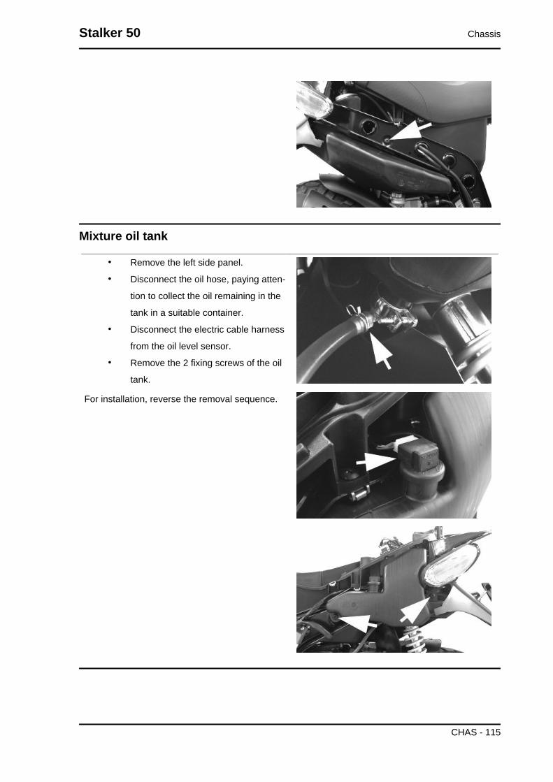
Mixture oil tank
• Remove the left side panel.
• Disconnect the oil hose, paying atten-
tion to collect the oil remaining in the
tank in a suitable container.
• Disconnect the electric cable harness
from the oil level sensor.
• Remove the 2 fixing screws of the oil
tank.
For installation, reverse the removal sequence.
Stalker 50 Chassis
CHAS - 115

INDEX OF TOPICS
PRE-DELIVERY PRE DE
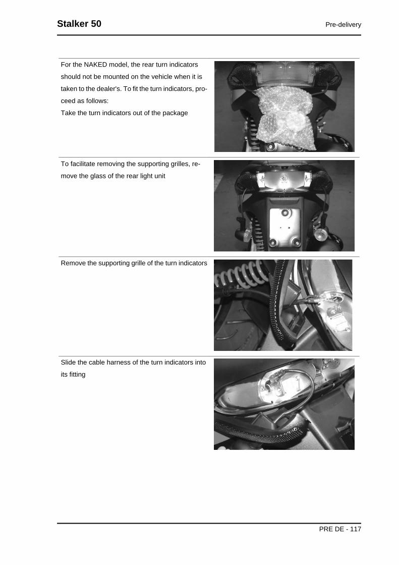
For the NAKED model, the rear turn indicators
should not be mounted on the vehicle when it is
taken to the dealer's. To fit the turn indicators, pro-
ceed as follows:
Take the turn indicators out of the package
To facilitate removing the supporting grilles, re-
move the glass of the rear light unit
Remove the supporting grille of the turn indicators
Slide the cable harness of the turn indicators into
its fitting
Stalker 50 Pre-delivery
PRE DE - 117

Place the turn indicator unit into its fitting and lock
it using the specific screw as indicated in the pho-
tograph
Refit the glass of the rear light unit.
Aesthetic inspection
Appearance check:
- Paintwork
- Fitting of plastics
- Scratches
- Dirt
Tightening torques inspection
Lock check
- Safety locks
- clamping screws
Safety locks
Pre-delivery Stalker 50
PRE DE - 118

Rear shock absorber upper fixing
Rear shock absorber lower fixing
Front wheel axle nut
Wheel hub nut
Frame - swinging arm bolt *
Swinging arm bolt - Engine
Engine arm pin - Frame arm
Handlebar lock nut
Steering lower ring nut
Upper steering ring nut
Electrical system
Electrical system:
- Main switch
- Headlamps: high beam, low beam, position and parking lights and the respective warning lights
- Adjusting the headlights according to the regulations currently in force
- Rear light, parking light, stop light
- Front and rear stop light switches
- Turn indicators and their warning lights
- Instrument panel lights
- Instrument panel: fuel and temperature indicator
- Instrument panel warning lights
- Horn
- StarterCAUTION
TO ENSURE MAXIMUM PERFORMANCE, THE BATTERY MUST BE CHARGED BEFORE USE.INADEQUATE CHARGING OF THE BATTERY WITH A LOW LEVEL OF ELECTROLYTE BEFOREIT IS FIRST USED SHORTENS BATTERY LIFE.WARNING
BEFORE RECHARGING THE BATTERY, REMOVE THE CAPS OF EACH CELL.KEEP THE BATTERY AWAY FROM NAKED FLAMES OR SPARKS WHILE IT IS CHARGED.REMOVE THE BATTERY FROM THE SCOOTER, DISCONNECTING THE NEGATIVE TERMINALFIRST.CAUTION
WHEN INSTALLING THE BATTERY, ATTACH THE POSITIVE LEAD FIRST AND THEN THE NEG-ATIVE LEAD.WARNING
BATTERY ELECTROLYTE IS TOXIC AND IT MAY CAUSE SERIOUS BURNS. IT CONTAINS SUL-PHURIC ACID. AVOID CONTACT WITH EYES, SKIN AND CLOTHING.IN CASE OF CONTACT WITH EYES OR SKIN, RINSE WITH ABUNDANT WATER FOR ABOUT 15MINUTES AND SEEK MEDICAL ATTENTION AT ONCE.IF IT IS SWALLOWED, IMMEDIATELY DRINK LARGE QUANTITIES OF WATER OR VEGETABLEOIL. SEEK IMMEDIATE MEDICAL ATTENTION.
Stalker 50 Pre-delivery
PRE DE - 119

BATTERIES PRODUCE EXPLOSIVE GAS; KEEP THEM AWAY FROM NAKED FLAMES, SPARKSAND CIGARETTES. IF THE BATTERY IS CHARGED IN A CLOSED PLACE, TAKE CARE TO EN-SURE ADEQUATE VENTILATION. ALWAYS PROTECT YOUR EYES WHEN WORKING CLOSE TOBATTERIES.KEEP OUT OF THE REACH OF CHILDRENCAUTIONNEVER USE FUSES WITH A CAPACITY HIGHER THAN THE RECOMMENDED CAPACITY. USINGA FUSE OF UNSUITABLE RATING MAY SERIOUSLY DAMAGE THE VEHICLE OR EVEN CAUSEA FIRE.
Levels check
Level check:
- Hydraulic brake system fluid level.
- Rear hub oil level
- Engine oil level
Road test
Test ride
- Cold start
- Instrument operations
- Response to the throttle control
- Stability on acceleration and braking
- Rear and front brake efficiency
- Rear and front suspension efficiency
- Abnormal noise
Static test
Static control after the test ride:
- Starting when warm
- Starter operation
- Minimum hold (turning the handlebar)
- Uniform turning of the steering
- Possible leaksCAUTIONCHECK AND ADJUST TYRE PRESSURE WITH TYRES AT AMBIENT TEMPERATURE.CAUTIONNEVER EXCEED THE RECOMMENDED INFLATION PRESSURES OR TYRES MAY BURST.
Functional inspection
Functional check up:
Braking system (hydraulic)
Pre-delivery Stalker 50
PRE DE - 120

- Lever travel
Braking system (mechanical)
- Lever travel
Clutch
- Proper functioning check
Engine
- Throttle travel check
Others
- Check documentation
- Check the frame and engine numbers
- Tool kit
- License plate fitting
- Check locks
- Check tyre pressures
- Installation of mirrors and any accessories
Stalker 50 Pre-delivery
PRE DE - 121

INDEX OF TOPICS
TIME TIME

This section is devoted to the time necessary to
carry out repairs.
The description and code for each operation is in-
dicated.
Engine
ENGINECode Action Duration
1 001001 Engine to chassis - Replacement
Stalker 50 Time
TIME - 123

Crankcase
CRANKCASECode Action Duration
1 001133 Engine crankcase - Replacement
Time Stalker 50
TIME - 124

Crankshaft
CRANKSHAFTCode Action Duration
1 001117 Crankshaft - Replacement2 001118 Main bearings - Replacement3 001099 Oil seal, flywheel side - Replacement4 001100 Oil seal, clutch side - Replacement
Stalker 50 Time
TIME - 125
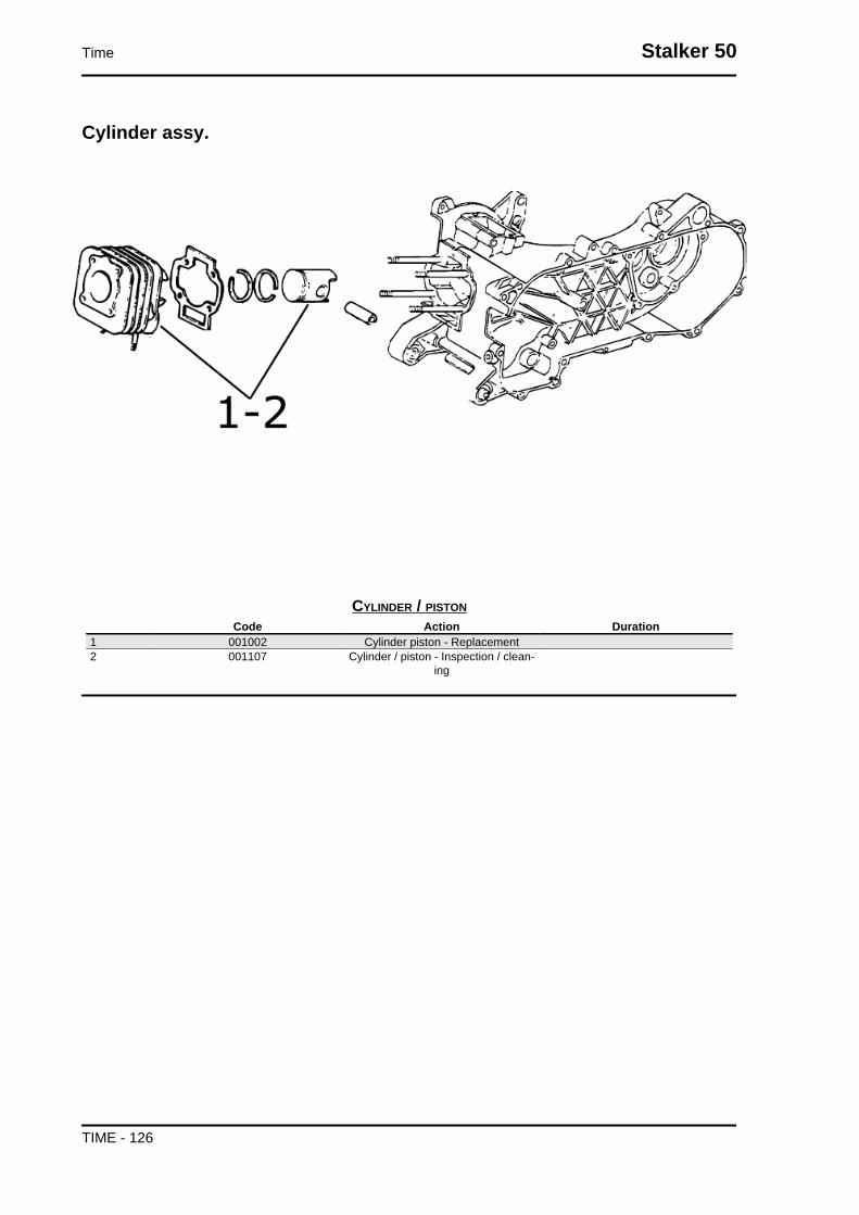
Cylinder assy.
CYLINDER / PISTONCode Action Duration
1 001002 Cylinder piston - Replacement2 001107 Cylinder / piston - Inspection / clean-
ing
Time Stalker 50
TIME - 126

Cylinder head assy.
CYLINDER HEAD ASSEMBLYCode Action Duration
1 001013 Intake manifold - Replacement2 001093 Spark plug - Replacement3 001126 Head - Replacement4 001097 Cooling hood - Replacement5 001178 Disc pack - Replacement6 001087 Flywheel cover - Replacement
Stalker 50 Time
TIME - 127
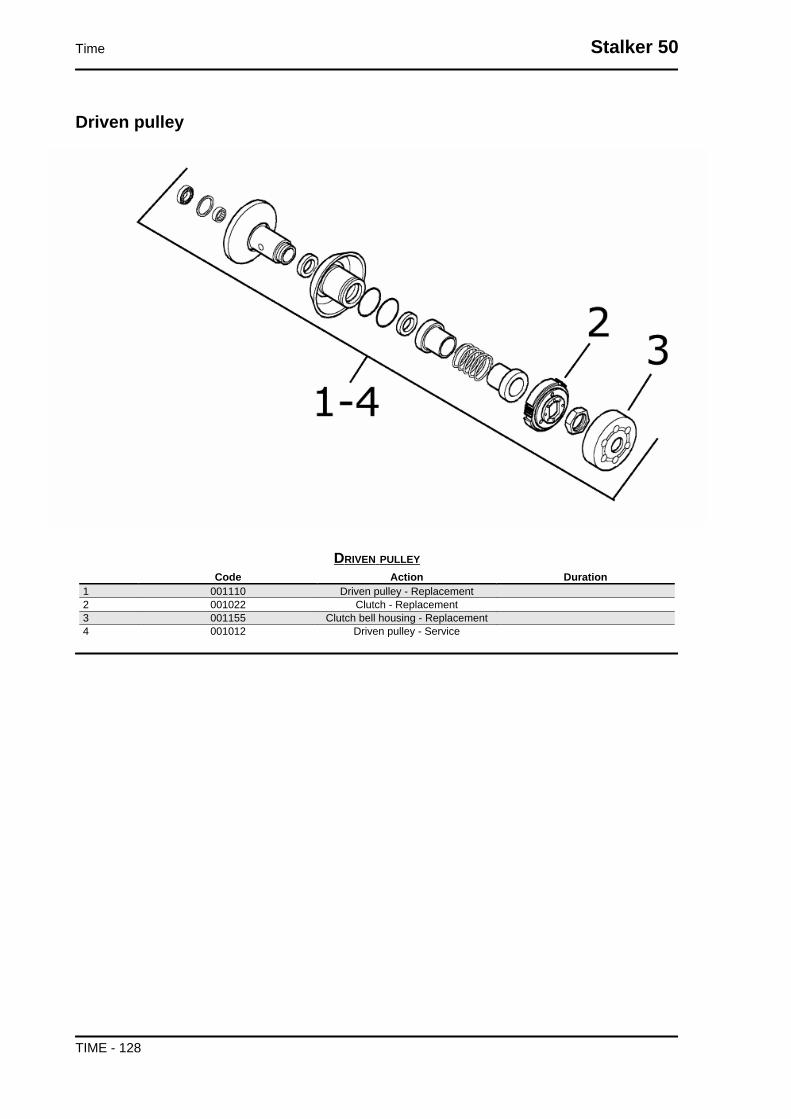
Driven pulley
DRIVEN PULLEYCode Action Duration
1 001110 Driven pulley - Replacement2 001022 Clutch - Replacement3 001155 Clutch bell housing - Replacement4 001012 Driven pulley - Service
Time Stalker 50
TIME - 128
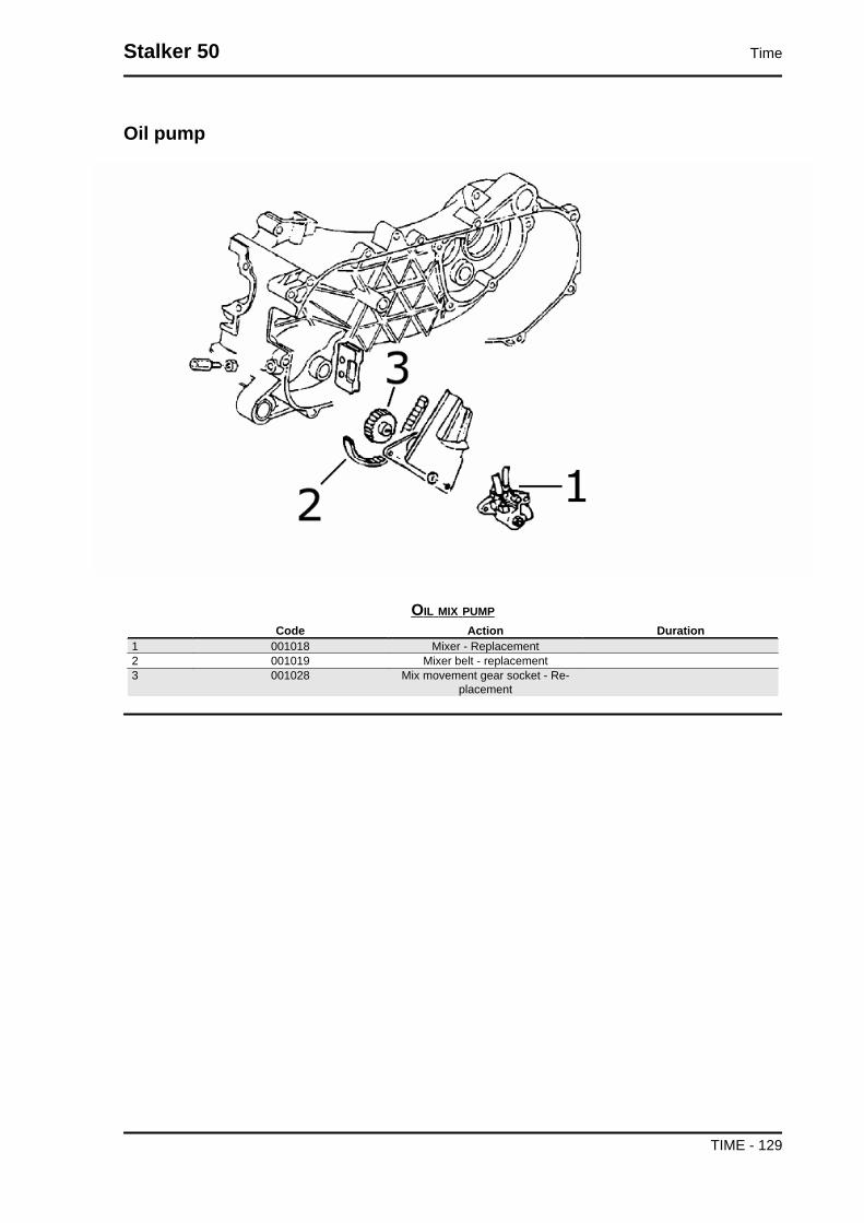
Oil pump
OIL MIX PUMPCode Action Duration
1 001018 Mixer - Replacement2 001019 Mixer belt - replacement3 001028 Mix movement gear socket - Re-
placement
Stalker 50 Time
TIME - 129

Final gear assy.
FINAL REDUCTION GEARCode Action Duration
1 001010 Geared reduction unit - Service2 001156 Gear reduction unit cover - Replace-
ment3 003065 Gear box oil - Replacement4 004125 Rear wheel axle - Replacement
Time Stalker 50
TIME - 130

Driving pulley
DRIVING PULLEYCode Action Duration
1 001011 Driving belt - Replacement2 001066 driving pulley - Replacement3 001017 Starter sprocket wheel - Replace-
ment4 001086 Driving half-pulley - replace5 001177 Variator rollers / shoes - Replace-
ment
Stalker 50 Time
TIME - 131

Transmission cover
TRANSMISSION COVERCode Action Duration
1 001096 Transmission crankcase cover - Re-placement
2 001131 Transmission air intake - Replace-ment
3 001135 Transmission cover bearing - Re-placement
4 004179 Stand buffer - Replacement
Time Stalker 50
TIME - 132

Starter motor
STARTER MOTOR AND KICK STARTERCode Action Duration
1 001020 Starter motor - Replacement2 001021 Kick starter - Inspection3 001084 Starter lever - Replacement4 008008 Starter spring pack - Replacement5 005045 Starter motor cable harness - Re-
placement
Stalker 50 Time
TIME - 133

Flywheel magneto
MAGNETO FLYWHEELCode Action Duration
1 001058 Flywheel - Replacement2 001067 Stator - Replacement3 001173 Rotor - Replacement4 001109 Cooling fan - Replacement
Time Stalker 50
TIME - 134

Brake shoes
BRAKE SHOESCode Action Duration
1 002002 Rear brake shoe(s) - Replacement
Stalker 50 Time
TIME - 135

Carburettor
CARBURETTOR INSPECTIONCode Action Duration
1 001081 Automatic choke - Replacement2 001008 Carburettor - Inspection
Time Stalker 50
TIME - 136

CARBURETTORCode Action Duration
1 001063 Carburettor - Replacement2 003058 Carburettor - Adjustment3 004177 Heating hood - Replacement
Exhaust pipe
MUFFLERCode Action Duration
1 001009 Muffler - Replacement2 001095 Muffler guard - Replacement3 001136 Exhaust emissions - Adjustment
Stalker 50 Time
TIME - 137

Air cleaner
AIR FILTERCode Action Duration
1 001014 Air filter - Replacement / cleaning2 001015 Air filter box - Replacement3 004122 Air cleaner carburettor fitting - Re-
placement
Time Stalker 50
TIME - 138
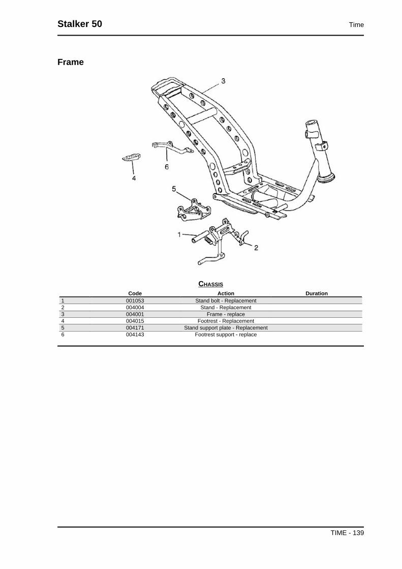
Frame
CHASSISCode Action Duration
1 001053 Stand bolt - Replacement2 004004 Stand - Replacement3 004001 Frame - replace4 004015 Footrest - Replacement5 004171 Stand support plate - Replacement6 004143 Footrest support - replace
Stalker 50 Time
TIME - 139

Legshield spoiler
FRONT SHIELDCode Action Duration
1 004064 Front shield - Replacement2 004065 Front shield rear section - Replace-
ment3 004178 Footrest - Replacement4 004053 Spoiler - Replacement
Time Stalker 50
TIME - 140

Side fairings
REAR COVERSCode Action Duration
1 xxxx Rear spoiler - Replacement2 004085 Fairing (1) - Replacement3 004012 Rear side panels (2) - Replacement4 xxxxx Lower cover side panel - Replace-
ment
Stalker 50 Time
TIME - 141

Underseat compartment
CENTRAL FRAME COVERCode Action Duration
1 004011 Central chassis cover - Replacement
Time Stalker 50
TIME - 142

HELMET COMPARTMENTCode Action Duration
1 004016 Helmet compartment - Replacement2 005046 Battery cover - Replacement
Mudguard
REAR MUDGUARDCode Action Duration
1 004009 Rear mudguard - Replacement
Stalker 50 Time
TIME - 143

Fuel tank
FUEL TANKCode Action Duration
1 004005 Fuel tank - Replacement2 005010 Tank float - Replacement3 004072 Fuel filter - Replacement4 004112 Cock / carburettor hose - Replace-
ment
Time Stalker 50
TIME - 144

Tank oil
OIL TANKCode Action Duration
1 004017 Oil reservoir - Replacement2 005018 Oil reservoir float - Replacement3 004095 Oil reservoir cock - Replacement4 004091 Oil reservoir hose - Replacement
Stalker 50 Time
TIME - 145

Rear shock-absorber
REAR SHOCK ABSORBERCode Action Duration
1 003007 Rear shock absorbers - Replace-ment
Time Stalker 50
TIME - 146

Steering column bearings
STEERING FIFTH WHEELSCode Action Duration
1 003002 Steering fifth wheel - Replacement2 003073 Steering clearance - Adjustment3 004119 Bearing / upper steering fifth wheel -
Replacement
Stalker 50 Time
TIME - 147

Handlebar components
HANDLEBAR COMPONENTSCode Action Duration
1 002071 Left hand grip - Replacement2 002037 Brake or clutch lever - Replacement3 005017 Stop switch - Replacement
Time Stalker 50
TIME - 148

HANDLEBAR COMPONENTSCode Action Duration
1 004066 Driving mirror - Replacement2 003001 Handlebar - Replacement3 005017 Stop switch - Replacement4 002037 Brake or clutch lever - Replacement5 002059 Right hand grip - Replacement
Stalker 50 Time
TIME - 149

Swing-arm
SWINGING ARMCode Action Duration
1 001072 Engine / frame swinging arm fitting -Replacement
Time Stalker 50
TIME - 150

Seat
SADDLECode Action Duration
1 004003 Saddle - Replacement
Stalker 50 Time
TIME - 151

Instrument panel
INSTRUMENT PANEL AND HANDLEBAR COVERCode Action Duration
1 005014 Odometer - Replacement2 004018 Handlebar front section - Replace-
ment3 004019 Handlebar rear section - Replace-
ment4 005078 Odometer glass - Replacement5 005076 Clock / Cell - Replacement
Time Stalker 50
TIME - 152

Turn signal lights
FRONT HEADLAMPCode Action Duration
1 005067 Front turn indicator bulb - Replace-ment
2 005008 Front headlamp bulbs - Replacement3 005002 Front headlamp - Replacement4 005091 Turn indicator glass - Replacement5 005012 Front turn indicator - Replacement
Stalker 50 Time
TIME - 153

REAR LIGHTSCode Action Duration
1 005022 Rear turn indicators - Replacement2 005068 Rear turn indicator bulb - Replace-
ment3 005091 Turn indicator glass - Replacement4 005028 Rear light assembly glass - Replace-
ment5 005066 Rear light bulbs - Replacement6 004136 License plate support - Replacement7 004056 Upper rear light cover - Replacement8 005048 Licence plate holder - Replacement
Time Stalker 50
TIME - 154

Front wheel
FRONT WHEELCode Action Duration
1 002041 Front brake disc - Replacement2 003040 Front wheel bearings - Replacement3 003037 Front wheel rim- Replacement4 003047 Front tyre - replace5 004123 Front wheel - Replacement6 003038 Front wheel axle - Replacement7 002011 Odometer movement sensor - Re-
placement
Grease tone wheel or drive
Please take note that the code has been intro-
duced:
900001 - Tone wheel / drive greasing - 15'.
Never mistake the codes 002011 (movement sen-
sor replacement) and 005089 (tone wheel replace-
ment) in the event of noise of the indicated
components. The grease recommended is TUTE-
LA MRM 2 (soap-based lithium grease with Mo-
lybdenum disulphide).
In the following points we indicate with an arrow
the area to be greased (1 - Drive, 2 - Tone wheel)
Stalker 50 Time
TIME - 155

Rear wheel
REAR WHEELCode Action Duration
1 001071 Rear wheel rim - Replacement2 001016 Rear wheel - Replacement3 004126 Rear wheel tyre - Replacement
Time Stalker 50
TIME - 156
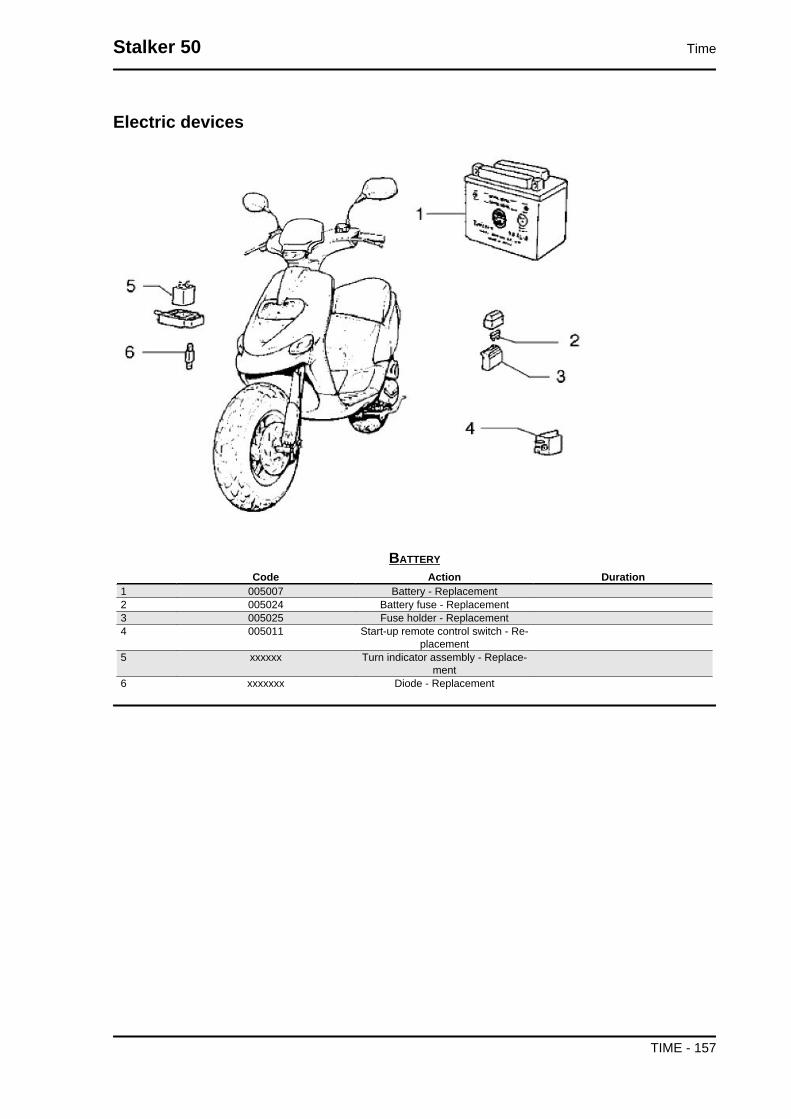
Electric devices
BATTERYCode Action Duration
1 005007 Battery - Replacement2 005024 Battery fuse - Replacement3 005025 Fuse holder - Replacement4 005011 Start-up remote control switch - Re-
placement5 xxxxxx Turn indicator assembly - Replace-
ment6 xxxxxxx Diode - Replacement
Stalker 50 Time
TIME - 157

ELECTRICAL SYSTEMCode Action Duration
1 001023 Control unit - Replacement2 001094 Spark plug cap - Replacement3 005001 Electrical system - Replacement4 005009 Voltage regulator - Replacement
Time Stalker 50
TIME - 158

Electronic controls
ELECTRIC CONTROLSCode Action Duration
1 005041 Starter button - Replacement2 005040 Horn button - Replacement3 005016 Key switch - Replacement4 004096 Lock series - Replacement5 004010 Antitheft lock - replace6 005003 Horn - Replacement7 005006 Light switch or turn indicators - Re-
placement8 005039 Headlight switch - Replacement9 005077 Emergency stop switch - Replace-
ment
Stalker 50 Time
TIME - 159

Transmissions
SPLITTERCode Action Duration
1 002012 Splitter - Replacement2 002058 Mix / splitter transmission complete -
Replacement3 002057 Carburettor / splitter transmission
complete - Replacement4 002054 Throttle or splitter transmission com-
plete - Replacement
Time Stalker 50
TIME - 160

REAR BRAKE TRANSMISSION AND ODOMETERCode Action Duration
1 002051 Odometer transmission assembly -Replacement
2 002053 Rear brake transmission complete -Replacement
Stalker 50 Time
TIME - 161

Front suspension
FORKCode Action Duration
1 003010 Front suspension - Service2 003051 Complete fork - replace3 003048 Fork oil seal - Replacement4 003041 Fork stanchion - Replacement
Time Stalker 50
TIME - 162

Braking system
FRONT BRAKECode Action Duration
1 002103 Brake fluid reservoir - Replacement2 002052 Front brake transmission - Replace-
ment3 002025 Brake piping - Replacement4 002021 Front brake piping - Replacement5 002039 Front brake calliper - Replacement6 002024 Front brake pump - replace
Stalker 50 Time
TIME - 163

AAir filter: 28
BBattery: 36, 43, 52Brake: 92, 99, 101, 102, 105, 135
CCarburettor: 10, 136
EEngine stop:
FFuel: 34, 87, 114, 144Fuses: 51
HHeadlight: 31, 109Hub oil: 26
IIdentification: 8Instrument panel: 108, 152
MMaintenance: 7, 25
OOdometer:
SSaddle: Spark plug: 26
TTank: 114, 115, 144, 145Transmission: 9, 35, 59, 132Tyres: 10