Embed Size (px)
Citation preview

Reference Manual00809-0100-4825, Rev CB
March 2014
Rosemount® 248 Temperature Transmitter

v
Reference Manual 00809-0100-4825, Rev CB
Rosemount 248 Temperature Transmitter
Rosemount 248 Hardware Revision
Headmount
Railmount
HART® Device Revision
Field Communicator Field Device Revision
4
1
5.1
Dev v1, DD v1
NOTICE
Read this manual before working with the product. For personal and system safety, and for optimum product performance, make sure to thoroughly understand the contents before installing, using, or maintaining this product.
The United States has two toll-free assistance numbers and one international number.
Customer Central1 800 999 9307 (7:00 a.m. to 7:00 P.M. CST)
National Response Center1 800 654 7768 (24 hours a day)Equipment service needs
International1 952 906 8888
The products described in this document are NOT designed for nuclear-qualified applications.
Using non-nuclear qualified products in applications that require nuclear-qualified hardware or products may cause inaccurate readings.
For information on Rosemount nuclear-qualified products, contact an Emerson Process Management Sales Representative.

Reference Manual 00809-0100-4825, Rev CB
Table of ContentsMarch 2014
viiTable of Contents
Content
1Section 1: Introduction1.1 Safety messages . . . . . . . . . . . . . . . . . . . . . . . . . . . . . . . . . . . . . . . . . . . . . . . . . . . . . . . . 1
1.1.1 Warnings . . . . . . . . . . . . . . . . . . . . . . . . . . . . . . . . . . . . . . . . . . . . . . . . . . . . . . . . 1
1.2 Overview . . . . . . . . . . . . . . . . . . . . . . . . . . . . . . . . . . . . . . . . . . . . . . . . . . . . . . . . . . . . . . 2
1.2.1 Manual . . . . . . . . . . . . . . . . . . . . . . . . . . . . . . . . . . . . . . . . . . . . . . . . . . . . . . . . . . 2
1.2.2 Transmitter . . . . . . . . . . . . . . . . . . . . . . . . . . . . . . . . . . . . . . . . . . . . . . . . . . . . . . 2
1.3 Considerations . . . . . . . . . . . . . . . . . . . . . . . . . . . . . . . . . . . . . . . . . . . . . . . . . . . . . . . . . 3
1.3.1 General . . . . . . . . . . . . . . . . . . . . . . . . . . . . . . . . . . . . . . . . . . . . . . . . . . . . . . . . . . 3
1.3.2 Commissioning . . . . . . . . . . . . . . . . . . . . . . . . . . . . . . . . . . . . . . . . . . . . . . . . . . . 3
1.3.3 Mechanical . . . . . . . . . . . . . . . . . . . . . . . . . . . . . . . . . . . . . . . . . . . . . . . . . . . . . . . 3
1.3.4 Electrical . . . . . . . . . . . . . . . . . . . . . . . . . . . . . . . . . . . . . . . . . . . . . . . . . . . . . . . . . 3
1.3.5 Environmental . . . . . . . . . . . . . . . . . . . . . . . . . . . . . . . . . . . . . . . . . . . . . . . . . . . . 4
1.4 Return of materials . . . . . . . . . . . . . . . . . . . . . . . . . . . . . . . . . . . . . . . . . . . . . . . . . . . . . 5
1.5 Product recycling/disposal . . . . . . . . . . . . . . . . . . . . . . . . . . . . . . . . . . . . . . . . . . . . . . . 5
2Section 2: Installation2.1 Safety messages . . . . . . . . . . . . . . . . . . . . . . . . . . . . . . . . . . . . . . . . . . . . . . . . . . . . . . . . 7
2.1.1 Warnings . . . . . . . . . . . . . . . . . . . . . . . . . . . . . . . . . . . . . . . . . . . . . . . . . . . . . . . . 7
2.2 Mounting . . . . . . . . . . . . . . . . . . . . . . . . . . . . . . . . . . . . . . . . . . . . . . . . . . . . . . . . . . . . . . 9
2.3 Installation. . . . . . . . . . . . . . . . . . . . . . . . . . . . . . . . . . . . . . . . . . . . . . . . . . . . . . . . . . . .10
2.3.1 Typical European and Asia Pacific installation . . . . . . . . . . . . . . . . . . . . . . . .10
2.3.2 Typical North and South American installation . . . . . . . . . . . . . . . . . . . . . . .11
2.4 Multichannel installations. . . . . . . . . . . . . . . . . . . . . . . . . . . . . . . . . . . . . . . . . . . . . . .14
2.5 Set the switches . . . . . . . . . . . . . . . . . . . . . . . . . . . . . . . . . . . . . . . . . . . . . . . . . . . . . . .14
2.5.1 Failure mode . . . . . . . . . . . . . . . . . . . . . . . . . . . . . . . . . . . . . . . . . . . . . . . . . . . .14
2.6 Wiring. . . . . . . . . . . . . . . . . . . . . . . . . . . . . . . . . . . . . . . . . . . . . . . . . . . . . . . . . . . . . . . .15
2.6.1 Sensor connections . . . . . . . . . . . . . . . . . . . . . . . . . . . . . . . . . . . . . . . . . . . . . .16
2.7 Power supply. . . . . . . . . . . . . . . . . . . . . . . . . . . . . . . . . . . . . . . . . . . . . . . . . . . . . . . . . .18
2.7.1 Surges/transients . . . . . . . . . . . . . . . . . . . . . . . . . . . . . . . . . . . . . . . . . . . . . . . .19
2.7.2 Ground the transmitter . . . . . . . . . . . . . . . . . . . . . . . . . . . . . . . . . . . . . . . . . . .19
3Section 3: Configuration3.1 Safety messages . . . . . . . . . . . . . . . . . . . . . . . . . . . . . . . . . . . . . . . . . . . . . . . . . . . . . . .23
3.1.1 Warnings . . . . . . . . . . . . . . . . . . . . . . . . . . . . . . . . . . . . . . . . . . . . . . . . . . . . . . .23
3.2 Commissioning. . . . . . . . . . . . . . . . . . . . . . . . . . . . . . . . . . . . . . . . . . . . . . . . . . . . . . . .24
3.2.1 Setting the loop to manual . . . . . . . . . . . . . . . . . . . . . . . . . . . . . . . . . . . . . . . .24
Reference Manual00809-0100-4825, Rev CB
Table of ContentsMarch 2014
3.3 AMS. . . . . . . . . . . . . . . . . . . . . . . . . . . . . . . . . . . . . . . . . . . . . . . . . . . . . . . . . . . . . . . . . .24
3.3.1 Apply AMS changes . . . . . . . . . . . . . . . . . . . . . . . . . . . . . . . . . . . . . . . . . . . . . .25
3.4 Field communicator. . . . . . . . . . . . . . . . . . . . . . . . . . . . . . . . . . . . . . . . . . . . . . . . . . . .25
3.4.1 HART traditional menu tree . . . . . . . . . . . . . . . . . . . . . . . . . . . . . . . . . . . . . . .26
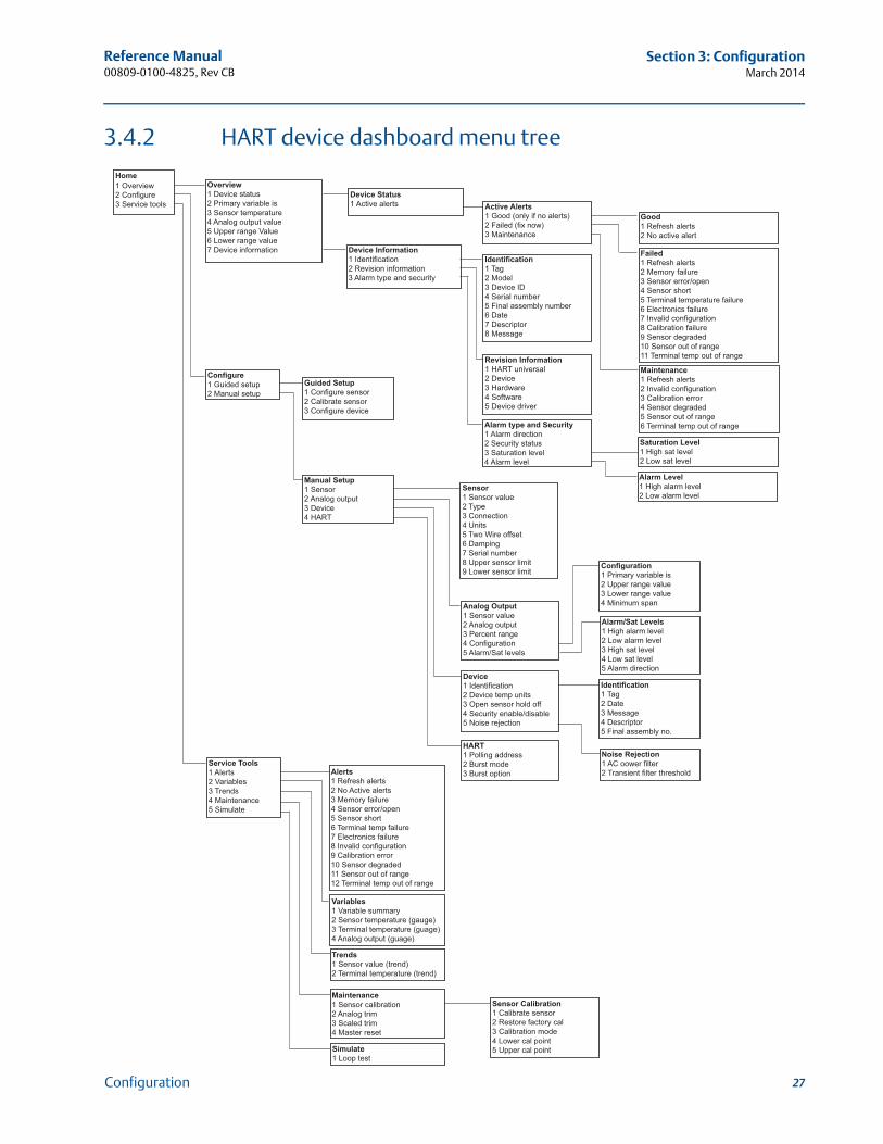
3.4.2 HART device dashboard menu tree . . . . . . . . . . . . . . . . . . . . . . . . . . . . . . . . .27
3.4.3 Fast Key sequence . . . . . . . . . . . . . . . . . . . . . . . . . . . . . . . . . . . . . . . . . . . . . . .28
3.4.4 Review configuration data . . . . . . . . . . . . . . . . . . . . . . . . . . . . . . . . . . . . . . . .30
3.4.5 Check output . . . . . . . . . . . . . . . . . . . . . . . . . . . . . . . . . . . . . . . . . . . . . . . . . . . .30
3.4.6 Configuration . . . . . . . . . . . . . . . . . . . . . . . . . . . . . . . . . . . . . . . . . . . . . . . . . . .30
3.4.7 Information variables . . . . . . . . . . . . . . . . . . . . . . . . . . . . . . . . . . . . . . . . . . . . .33
3.4.8 Diagnostics and service . . . . . . . . . . . . . . . . . . . . . . . . . . . . . . . . . . . . . . . . . . .34
3.5 Multidrop communication . . . . . . . . . . . . . . . . . . . . . . . . . . . . . . . . . . . . . . . . . . . . . .39
3.6 Rosemount 248 Configuration Interface specifications . . . . . . . . . . . . . . . . . . . . .40
3.6.1 Configuration software . . . . . . . . . . . . . . . . . . . . . . . . . . . . . . . . . . . . . . . . . . .40
3.6.2 Configuration hardware . . . . . . . . . . . . . . . . . . . . . . . . . . . . . . . . . . . . . . . . . .40
3.6.3 Rosemount 248 PC Programmer Kit installation . . . . . . . . . . . . . . . . . . . . .41
4Section 4: Operation and maintenance4.1 Safety messages . . . . . . . . . . . . . . . . . . . . . . . . . . . . . . . . . . . . . . . . . . . . . . . . . . . . . . .43
4.1.1 Warnings . . . . . . . . . . . . . . . . . . . . . . . . . . . . . . . . . . . . . . . . . . . . . . . . . . . . . . .43
4.2 Calibration . . . . . . . . . . . . . . . . . . . . . . . . . . . . . . . . . . . . . . . . . . . . . . . . . . . . . . . . . . . .44
4.2.1 Trim the transmitter. . . . . . . . . . . . . . . . . . . . . . . . . . . . . . . . . . . . . . . . . . . . . .44
4.3 Hardware . . . . . . . . . . . . . . . . . . . . . . . . . . . . . . . . . . . . . . . . . . . . . . . . . . . . . . . . . . . . .46
4.3.1 Maintenance . . . . . . . . . . . . . . . . . . . . . . . . . . . . . . . . . . . . . . . . . . . . . . . . . . . .46
4.4 Diagnostic messages. . . . . . . . . . . . . . . . . . . . . . . . . . . . . . . . . . . . . . . . . . . . . . . . . . .47
4.4.1 Hardware . . . . . . . . . . . . . . . . . . . . . . . . . . . . . . . . . . . . . . . . . . . . . . . . . . . . . . .47
4.4.2 Field communicator . . . . . . . . . . . . . . . . . . . . . . . . . . . . . . . . . . . . . . . . . . . . . .49
AAppendix A: Specifications and reference dataA.1 Transmitter specifications . . . . . . . . . . . . . . . . . . . . . . . . . . . . . . . . . . . . . . . . . . . . . .51
A.1.1 Functional specifications . . . . . . . . . . . . . . . . . . . . . . . . . . . . . . . . . . . . . . . . . .51
A.1.2 Physical specifications . . . . . . . . . . . . . . . . . . . . . . . . . . . . . . . . . . . . . . . . . . . .53
A.1.3 Performance specifications. . . . . . . . . . . . . . . . . . . . . . . . . . . . . . . . . . . . . . . .54
A.2 Sensor specifications . . . . . . . . . . . . . . . . . . . . . . . . . . . . . . . . . . . . . . . . . . . . . . . . . . .57
A.2.1 Thermocouples – IEC 584 . . . . . . . . . . . . . . . . . . . . . . . . . . . . . . . . . . . . . . . . .57
A.2.2 Thermocouples – ASTM E- 230 . . . . . . . . . . . . . . . . . . . . . . . . . . . . . . . . . . . .58
A.2.3 RTDs . . . . . . . . . . . . . . . . . . . . . . . . . . . . . . . . . . . . . . . . . . . . . . . . . . . . . . . . . . .58
A.2.4 Thermowells . . . . . . . . . . . . . . . . . . . . . . . . . . . . . . . . . . . . . . . . . . . . . . . . . . . .59
viii Table of Contents
Reference Manual 00809-0100-4825, Rev CB
Table of ContentsMarch 2014
A.3 Dimensional drawings. . . . . . . . . . . . . . . . . . . . . . . . . . . . . . . . . . . . . . . . . . . . . . . . . .60
A.4 Ordering information . . . . . . . . . . . . . . . . . . . . . . . . . . . . . . . . . . . . . . . . . . . . . . . . . .62
BAppendix B: Product CertificationsB.1 Approved Manufacturing Locations . . . . . . . . . . . . . . . . . . . . . . . . . . . . . . . . . . . . . .65
B.2 European Directive Information . . . . . . . . . . . . . . . . . . . . . . . . . . . . . . . . . . . . . . . . .65
B.3 Ordinary Location Certification from FM Approvals . . . . . . . . . . . . . . . . . . . . . . . .65
B.3.1 North America . . . . . . . . . . . . . . . . . . . . . . . . . . . . . . . . . . . . . . . . . . . . . . . . . . .65
B.3.2 Europe. . . . . . . . . . . . . . . . . . . . . . . . . . . . . . . . . . . . . . . . . . . . . . . . . . . . . . . . . .66
B.3.3 International . . . . . . . . . . . . . . . . . . . . . . . . . . . . . . . . . . . . . . . . . . . . . . . . . . . .68
B.3.4 China . . . . . . . . . . . . . . . . . . . . . . . . . . . . . . . . . . . . . . . . . . . . . . . . . . . . . . . . . . .69
B.3.5 Combinations . . . . . . . . . . . . . . . . . . . . . . . . . . . . . . . . . . . . . . . . . . . . . . . . . . .71
B.3.6 Tables . . . . . . . . . . . . . . . . . . . . . . . . . . . . . . . . . . . . . . . . . . . . . . . . . . . . . . . . . .72
B.4 Installation drawings . . . . . . . . . . . . . . . . . . . . . . . . . . . . . . . . . . . . . . . . . . . . . . . . . . .72
ixTable of Contents


Reference Manual 00809-0100-4825, Rev CB
Section 1: IntroductionMarch 2014
Section 1 Introduction
Safety messages . . . . . . . . . . . . . . . . . . . . . . . . . . . . . . . . . . . . . . . . . . . . . . . . . . . . . . . . . . . . page 1Overview . . . . . . . . . . . . . . . . . . . . . . . . . . . . . . . . . . . . . . . . . . . . . . . . . . . . . . . . . . . . . . . . . . page 2Considerations . . . . . . . . . . . . . . . . . . . . . . . . . . . . . . . . . . . . . . . . . . . . . . . . . . . . . . . . . . . . . page 3Return of materials . . . . . . . . . . . . . . . . . . . . . . . . . . . . . . . . . . . . . . . . . . . . . . . . . . . . . . . . . . page 5Product recycling/disposal . . . . . . . . . . . . . . . . . . . . . . . . . . . . . . . . . . . . . . . . . . . . . . . . . . . page 5
1.1 Safety messages
Instructions and procedures in this section may require special precautions to ensure the safety of the personnel performing the operations. Information that potentially raises safety issues is indicated by a warning symbol ( ). Please refer to the following safety messages before performing an operation preceded by this symbol.
1.1.1 Warnings
Failure to follow these installation guidelines could result in death orserious injury.
Make sure only qualified personnel perform the installation.Explosions could result in death or serious injury.
Do not remove the connection head cover in explosive atmospheres when the circuit is live.
Before connecting a Field Communicator in an explosive atmosphere, make sure the instruments in the loop are installed in accordance with intrinsically safe or non-intrinsic field wiring practices.
Verify that the operating atmosphere of the transmitter is consistent with the appropriate hazardous locations certifications.
All connection head covers must be fully engaged to meet explosion-proof requirements.
Process leaks could result in death or serious injury.
Do not remove the thermowell while in operation. Install and tighten thermowells and sensors before applying pressureElectrical shock could cause death or serious injury.
Use extreme caution when making contact with the leads and terminals.
1Introduction
Reference Manual00809-0100-4825, Rev CB
Section 1: IntroductionMarch 2014
1.2 Overview
1.2.1 Manual
This manual is designed to assist in the installation, operation, and maintenance of the Rosemount 248 Temperature Transmitter.
Section 1: Introduction
Transmitter and Manual Overview
Things to considerations
How to return the transmitter
Section 2: Installation
How to mount the transmitter
How to Install the transmitter
How to set the switches to ensure proper use
How to wire and power up the transmitter
Section 3: Configuration
Commissioning to transmitter
How to use the Field Communicator to configure the transmitter
Section 4: Operation and maintenance
Calibration the transmitter
Explanation of hardware maintenance and diagnostic messages
Appendix A: Specifications and reference data
Transmitter and Sensor Specifications
Dimensional drawings
Ordering Information
Appendix B: Product Certifications
Product Certifications/Hazardous Locations Certifications
Installation Drawings
1.2.2 Transmitter
Features of the Rosemount 248 include:
Acceptance of inputs from a wide variety of RTD and thermocouple sensors
Configuration using HART protocol
Electronics encapsulated in epoxy and enclosed in a plastic housing, making the transmitter extremely durable and ensuring long-term reliability
A compact size and three housing options that allow mounting flexibility in the field
2 Introduction
Reference Manual 00809-0100-4825, Rev CB
Section 1: IntroductionMarch 2014
Refer to the following literature for sensors, thermowells, and extensions that form a complete point solution with the Rosemount 248:
Temperature Sensors and Assemblies Product Data Sheet, Volume 1 (Document No. 00813-0100-2654)
Temperature Sensors and Assemblies Product Data Sheet, Volume 2 (Document No. 00813-0200-2654)
Temperature sensors and Assemblies Product Data Sheet, Volume 3 (Document No. 00813-0301-2654)
1.3 Considerations
1.3.1 General
Electrical temperature sensors, such as RTDs and thermocouples, produce low-level signals proportional to the sensed temperature. The Rosemount 248 converts the low-level sensor signal to a standard 4–20 mA dc signal that is relatively insensitive to lead length and electrical noise. This current signal is transmitted to the control room through two wires.
1.3.2 Commissioning
The transmitter may be commissioned before or after installation. It can be useful to commission it on the bench, before installation, to ensure proper operation and to become familiar with its functionality. The instruments in the loop should be installed according to the intrinsically safe or non-incendive field wiring practices before connecting a Field Communicator in an explosive atmosphere. For more information, see “Commissioning” on page 24.
1.3.3 Mechanical
Location
When choosing an installation location, take into account access to the transmitter.
Special mounting
Special hardware is available for mounting a Rosemount 248 head mount transmitter to a DIN rail.
1.3.4 Electrical
Proper electrical installation is necessary to prevent errors from sensor lead resistance and electrical noise. For best results, shielded cable should be used in electrically noisy environments. A resistance between 250 and 1100 ohms must be present in the loop for communication with a Field Communicator.
Make wiring connections through the cable entry in the side of the connection head being sure to provide adequate clearance for cover removal.
3Introduction
Reference Manual00809-0100-4825, Rev CB
Section 1: IntroductionMarch 2014
1.3.5 Environmental
The transmitter electronics module is permanently sealed within the housing, to resist moisture and corrosive damage. Verify that the operating atmosphere of the transmitter is consistent with the appropriate hazardous locations certifications.
Temperature effects
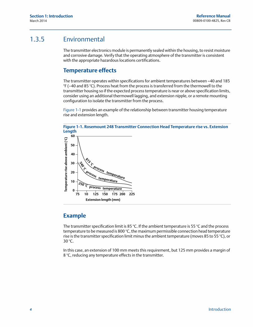
The transmitter operates within specifications for ambient temperatures between –40 and 185 °F (–40 and 85 °C). Process heat from the process is transferred from the thermowell to the transmitter housing so if the expected process temperature is near or above specification limits, consider using an additional thermowell lagging, and extension nipple, or a remote mounting configuration to isolate the transmitter from the process.
Figure 1-1 provides an example of the relationship between transmitter housing temperature rise and extension length.
Figure 1-1. Rosemount 248 Transmitter Connection Head Temperature rise vs. Extension Length
Example
The transmitter specification limit is 85 °C. If the ambient temperature is 55 °C and the process temperature to be measured is 800 °C, the maximum permissible connection head temperature rise is the transmitter specification limit minus the ambient temperature (moves 85 to 55 °C), or 30 °C.
In this case, an extension of 100 mm meets this requirement, but 125 mm provides a margin of 8 °C, reducing any temperature effects in the transmitter.
60
50
40
30
20
10
075 10 125 150 175 200 225
Tem
per
atu
re r
ise
abov
e am
bie
nt
(°C
)
Extension length (mm)
815 °C
process temperature
540 °Cprocess
temperature250 °C process temperature
4 Introduction

Reference Manual 00809-0100-4825, Rev CB
Section 1: IntroductionMarch 2014
1.4 Return of materials
To expedite the return process in North America, call the Emerson Process Management National Response Center toll-free at 800-654-7768. This center is available 24 hours a day and will assist you with any needed information or materials.
The center will ask for the following information:
Product model
Serial numbers
The last process material to which the product was exposed
The center will provide
A Return Material Authorization (RMA) number
Instructions and procedures that are necessary to return goods that were exposed to hazardous substances
NoteIf a hazardous substance is identified, a Material Safety Data Sheet (MSDS), required by law to be available to people exposed to specific hazardous substances, must be included with the returned materials.
Outside North America, contact a local Emerson Process Management representative.
1.5 Product recycling/disposal
Recycling of equipment and packaging should be taken into consideration and disposed of in accordance with local and national legislation/regulations.
5Introduction


Reference Manual 00809-0100-4825, Rev CB
Section 2: InstallationMarch 2014
Section 2 Installation
Safety messages . . . . . . . . . . . . . . . . . . . . . . . . . . . . . . . . . . . . . . . . . . . . . . . . . . . . . . . . . . . . page 7Mounting . . . . . . . . . . . . . . . . . . . . . . . . . . . . . . . . . . . . . . . . . . . . . . . . . . . . . . . . . . . . . . . . . . page 9Installation . . . . . . . . . . . . . . . . . . . . . . . . . . . . . . . . . . . . . . . . . . . . . . . . . . . . . . . . . . . . . . . . . page 10Set the switches . . . . . . . . . . . . . . . . . . . . . . . . . . . . . . . . . . . . . . . . . . . . . . . . . . . . . . . . . . . . page 14Wiring . . . . . . . . . . . . . . . . . . . . . . . . . . . . . . . . . . . . . . . . . . . . . . . . . . . . . . . . . . . . . . . . . . . . . page 15Power supply . . . . . . . . . . . . . . . . . . . . . . . . . . . . . . . . . . . . . . . . . . . . . . . . . . . . . . . . . . . . . . . page 18
2.1 Safety messages
Instructions and procedures in this section may require special precautions to ensure the safety of the personnel performing the operations. Information that potentially raises safety issues is indicated by a warning symbol ( ). Please refer to the following safety messages before performing an operation preceded by this symbol.
2.1.1 Warnings
Failure to follow these installation guidelines could result in death orserious injury.
Make sure only qualified personnel perform the installation.Explosions could result in death or serious injury.
Do not remove the connection head cover in explosive atmospheres when the circuit is live.
Before connecting a communicator in an explosive atmosphere, make sure the instruments in the loop are installed in accordance with intrinsically safe or non-incendive field wiring practices.
Verify that the operating atmosphere of the transmitter is consistent with the appropriate hazardous locations certifications.
All connection head covers must be fully engaged to meet explosion-proof requirements.
Process leaks could result in death or serious injury.
Do not remove the thermowell while in operation. Install and tighten thermowells and sensors before applying pressureElectrical shock could cause death or serious injury.
Use extreme caution when making contact with the leads and terminals.
7Installation
Reference Manual00809-0100-4825, Rev CB
Section 2: InstallationMarch 2014
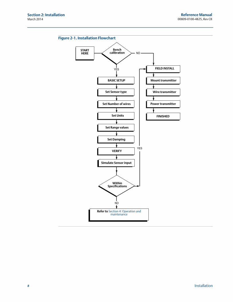
Figure 2-1. Installation Flowchart
START HERE
Bench calibration
BASIC SETUP
Set Sensor type
Set Number of wires
Set Units
Set Range values
Set Damping
VERIFY
Simulate Sensor input
Within Specifications
Refer to Section 4: Operation and maintenance
FIELD INSTALL
Mount transmitter
Wire transmitter
Power transmitter
FINISHED
8 Installation
Reference Manual 00809-0100-4825, Rev CB
Section 2: InstallationMarch 2014
2.2 Mounting
Mount the transmitter at a high point in the conduit run to prevent moisture from draining into the transmitter housing.
The Rosemount 248R installs directly to a wall or to a DIN rail.
The Rosemount 248H installs:
In a connection head or universal head mounted directly on a sensor assembly
Apart from a sensor assembly using a universal head
To a DIN rail using an optional mounting clip
Mounting a Rosemount 248H to a DIN rail
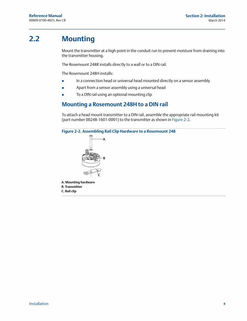
To attach a head mount transmitter to a DIN rail, assemble the appropriate rail mounting kit (part number 00248-1601-0001) to the transmitter as shown in Figure 2-2.
Figure 2-2. Assembling Rail Clip Hardware to a Rosemount 248
A. Mounting hardwareB. TransmitterC. Rail clip
B
A
C
9Installation

Reference Manual00809-0100-4825, Rev CB
Section 2: InstallationMarch 2014
2.3 Installation
The Rosemount 248 can be ordered assembled to a sensor and thermowell or as a stand-alone unit. If ordered without the sensor assembly, use the following guidelines when installing the transmitter with an integral sensor assembly.
2.3.1 Typical European and Asia Pacific installation
Head mount transmitter with DIN plate style sensor
1. Attach the thermowell to the pipe or process container wall then install and tighten the thermowell before applying process pressure.
2. Assemble the transmitter to the sensor. Push the transmitter mounting screws through the sensor mounting plate and insert the snap rings (optional) into the transmitter mounting screw groove.
3. Wire the sensor to the transmitter (see “Sensor wiring Diagrams” on page 16).
4. Insert the transmitter-sensor assembly into the connection head. Thread the transmitter mounting screw into the connection head mounting holes and assemble the extension to the connection head then insert the assembly into the thermowell.
5. Slip the shielded cable though the cable gland
6. Attach a cable gland into the shielded cable.
7. Insert the shielded cable leads into the connection head through the cable entry then connect and tighten the cable gland.
8. Connect the shielded power cable leads to the transmitter power terminals making sure to avoid contact with sensor leads and sensor connections.
9. Install and tighten the connection head cover making sure the enclosure covers are fully engaged to meet explosion-proof requirements.
A. Rosemount 248 transmitter D. Transmitter mounting screwsB. Connection head E. Integral mount sensor with flying leadsC. Thermowell F. Extension
A
D
B
C
E F
10 Installation
Reference Manual 00809-0100-4825, Rev CB
Section 2: InstallationMarch 2014
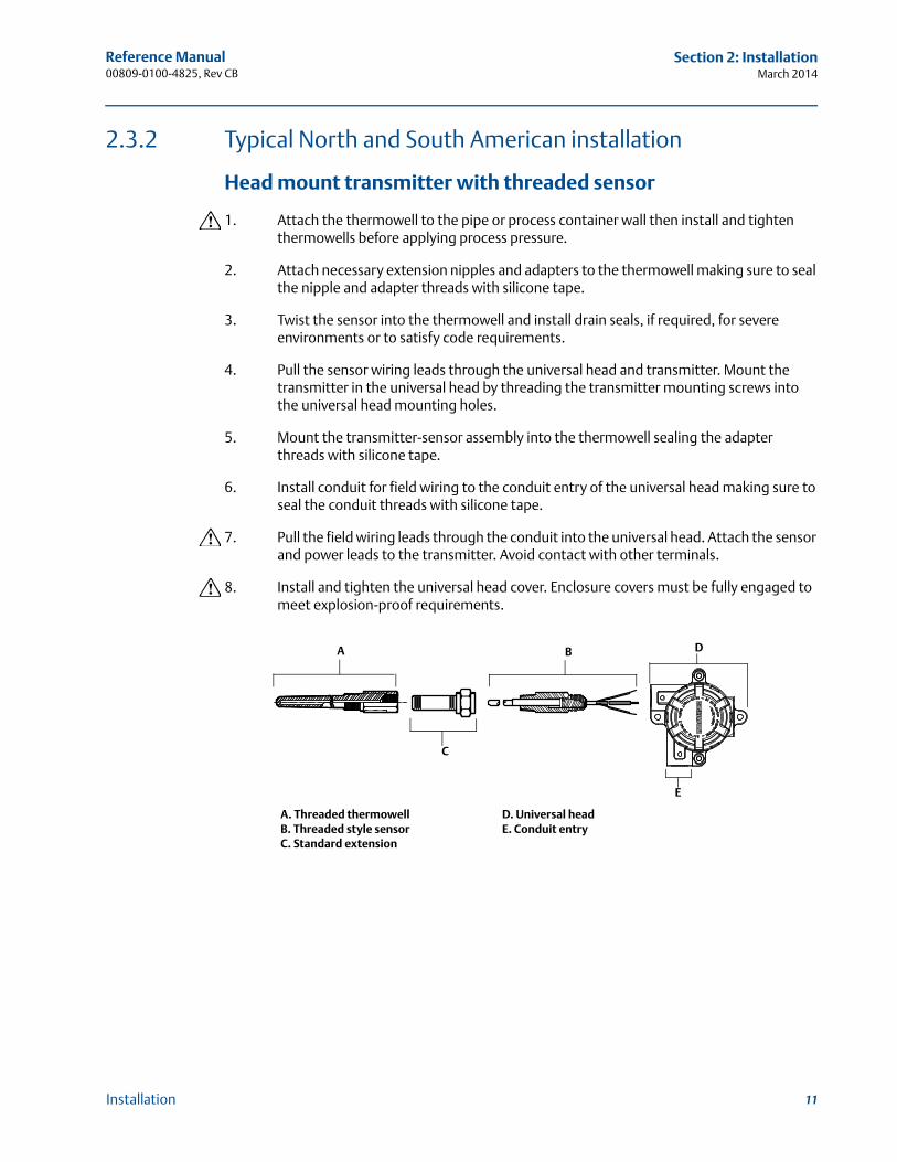
2.3.2 Typical North and South American installation
Head mount transmitter with threaded sensor
1. Attach the thermowell to the pipe or process container wall then install and tighten thermowells before applying process pressure.
2. Attach necessary extension nipples and adapters to the thermowell making sure to seal the nipple and adapter threads with silicone tape.
3. Twist the sensor into the thermowell and install drain seals, if required, for severe environments or to satisfy code requirements.
4. Pull the sensor wiring leads through the universal head and transmitter. Mount the transmitter in the universal head by threading the transmitter mounting screws into the universal head mounting holes.
5. Mount the transmitter-sensor assembly into the thermowell sealing the adapter threads with silicone tape.
6. Install conduit for field wiring to the conduit entry of the universal head making sure to seal the conduit threads with silicone tape.
7. Pull the field wiring leads through the conduit into the universal head. Attach the sensor and power leads to the transmitter. Avoid contact with other terminals.
8. Install and tighten the universal head cover. Enclosure covers must be fully engaged to meet explosion-proof requirements.
A. Threaded thermowell D. Universal headB. Threaded style sensor E. Conduit entryC. Standard extension
A B
C
D
E
11Installation
Reference Manual00809-0100-4825, Rev CB
Section 2: InstallationMarch 2014
12 Installation
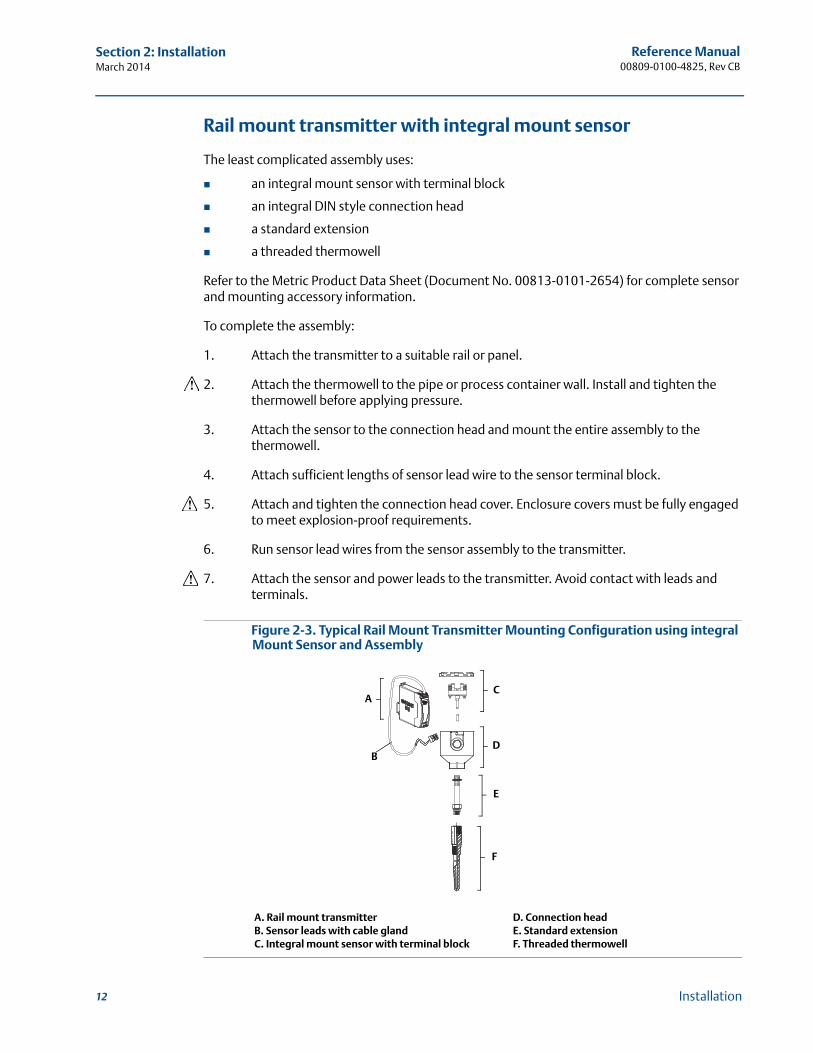
Rail mount transmitter with integral mount sensor
The least complicated assembly uses:
an integral mount sensor with terminal block
an integral DIN style connection head
a standard extension
a threaded thermowell
Refer to the Metric Product Data Sheet (Document No. 00813-0101-2654) for complete sensor and mounting accessory information.
To complete the assembly:
1. Attach the transmitter to a suitable rail or panel.
2. Attach the thermowell to the pipe or process container wall. Install and tighten the thermowell before applying pressure.
3. Attach the sensor to the connection head and mount the entire assembly to the thermowell.
4. Attach sufficient lengths of sensor lead wire to the sensor terminal block.
5. Attach and tighten the connection head cover. Enclosure covers must be fully engaged to meet explosion-proof requirements.
6. Run sensor lead wires from the sensor assembly to the transmitter.
7. Attach the sensor and power leads to the transmitter. Avoid contact with leads and terminals.
Figure 2-3. Typical Rail Mount Transmitter Mounting Configuration using integral Mount Sensor and Assembly
A. Rail mount transmitter D. Connection headB. Sensor leads with cable gland E. Standard extensionC. Integral mount sensor with terminal block F. Threaded thermowell
C
D
E
F
A
B
Reference Manual 00809-0100-4825, Rev CB
Section 2: InstallationMarch 2014
13Installation
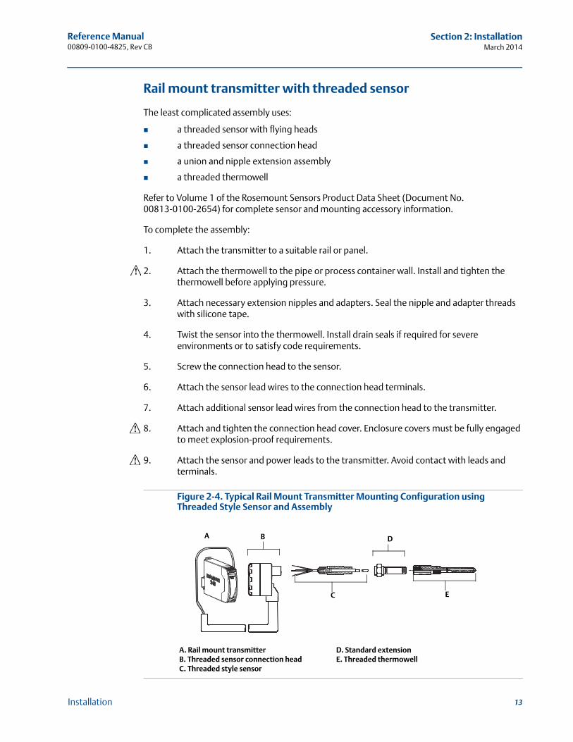
Rail mount transmitter with threaded sensor
The least complicated assembly uses:
a threaded sensor with flying heads
a threaded sensor connection head
a union and nipple extension assembly
a threaded thermowell
Refer to Volume 1 of the Rosemount Sensors Product Data Sheet (Document No. 00813-0100-2654) for complete sensor and mounting accessory information.
To complete the assembly:
1. Attach the transmitter to a suitable rail or panel.
2. Attach the thermowell to the pipe or process container wall. Install and tighten the thermowell before applying pressure.
3. Attach necessary extension nipples and adapters. Seal the nipple and adapter threads with silicone tape.
4. Twist the sensor into the thermowell. Install drain seals if required for severe environments or to satisfy code requirements.
5. Screw the connection head to the sensor.
6. Attach the sensor lead wires to the connection head terminals.
7. Attach additional sensor lead wires from the connection head to the transmitter.
8. Attach and tighten the connection head cover. Enclosure covers must be fully engaged to meet explosion-proof requirements.
9. Attach the sensor and power leads to the transmitter. Avoid contact with leads and terminals.
Figure 2-4. Typical Rail Mount Transmitter Mounting Configuration using Threaded Style Sensor and Assembly
A. Rail mount transmitter D. Standard extensionB. Threaded sensor connection head E. Threaded thermowellC. Threaded style sensor
A
C E
D B

Reference Manual00809-0100-4825, Rev CB
Section 2: InstallationMarch 2014
2.4 Multichannel installations
Several transmitters can be connected to a single master power supply, as shown in Figure 2-5. In this case, the system may be grounded only at the negative power supply terminal. In multichannel installations, where several transmitters are dependent on one power supply and the loss of all transmitters would cause operational problems, consider an uninterrupted power supply or a back-up battery. The diodes shown in Figure 2-5 prevent unwanted charging or discharging of the back-up battery.
Figure 2-5. Multichannel Installations
2.5 Set the switches
2.5.1 Failure mode
Each transmitter continuously monitors its performance during normal operation with an automatic diagnostic routine of continuous timed series of checks. If an input sensor failure or a transmitter electronics failure is detected, the transmitter outputs the low or high alarm, depending on the failure mode configuration.
For sensor temperature outside of range limits:
Standard Saturation Levels:
3.90 mA on the low end
20.5 mA on the high end
NAMUR-Compliant Saturation Levels:
3.80 mA on the low end
20.5 mA on the high end
These values are also custom configurable by the factory or using the Field Communicator or AMS. See “Alarm and saturation” on page 36 for instructions on how to change the alarm and saturation levels with the Field Communicator.
A. Transmitter no. 1 E. Readout or Controller no. 2B. Transmitter no. 2 F. Backup batteryC. RLead G. dc Power supplyD. Readout or Controller no. 1 H. To additional transmitters
A
B
C
C
C
D
E
H
G
F
Between 250 and 1100 if no load resistor.
14 Installation
Reference Manual 00809-0100-4825, Rev CB
Section 2: InstallationMarch 2014
NoteMicroprocessor failures cause high alarm regardless of alarm direction (high or low) choice.
The values the transmitter drives its output in failure mode depend on if it is configured to standard, NAMUR-compliant, or custom operation. See “Software detected failure mode” on page 52 for standard and NAMUR-compliant operation parameters.
2.6 Wiring
All power to the transmitter is supplied over the signal wiring. Ordinary copper wire of sufficient size should be used to ensure the voltage across the transmitter power terminals does not drop below 12.0 Vdc. Verify that the operating atmosphere of the transmitter is consistent with the appropriate hazardous locations certifications. Always use extreme caution when making contact with the leads and terminals.
If the sensor is installed in a high-voltage environment and a fault condition or installation error occurs, the sensor leads and transmitter terminals could carry lethal voltages. Use extreme caution when making contact with the leads and terminals.
NoteDo not apply high voltage (e.g., ac line voltage) to the transmitter terminals since high voltage can damage the unit. (Sensor and transmitter power terminals are rated up to 42.4 Vdc.) Use extreme caution when making contact with the leads and terminals.
For multichannel installations, see page 14. The transmitters accept inputs from a variety of RTD and thermocouple types. Refer to Figure 2-7 on page 16 when making sensor connections.
Use the following steps to wire the transmitter:
1. Remove the terminal block cover (if applicable).
2. Connect the positive power lead to the “+” terminal. Connect the negative power lead to the “–” terminal (see Figure 2-6). Use extreme caution when making contact with the leads and terminals.
3. Tighten the terminal screws.
4. Reattach and tighten the cover (if applicable). All connection head covers must be fully engaged to meet explosion-proof requirements.
5. Apply power (see “Power supply”).
15Installation
Reference Manual00809-0100-4825, Rev CB
Section 2: InstallationMarch 2014
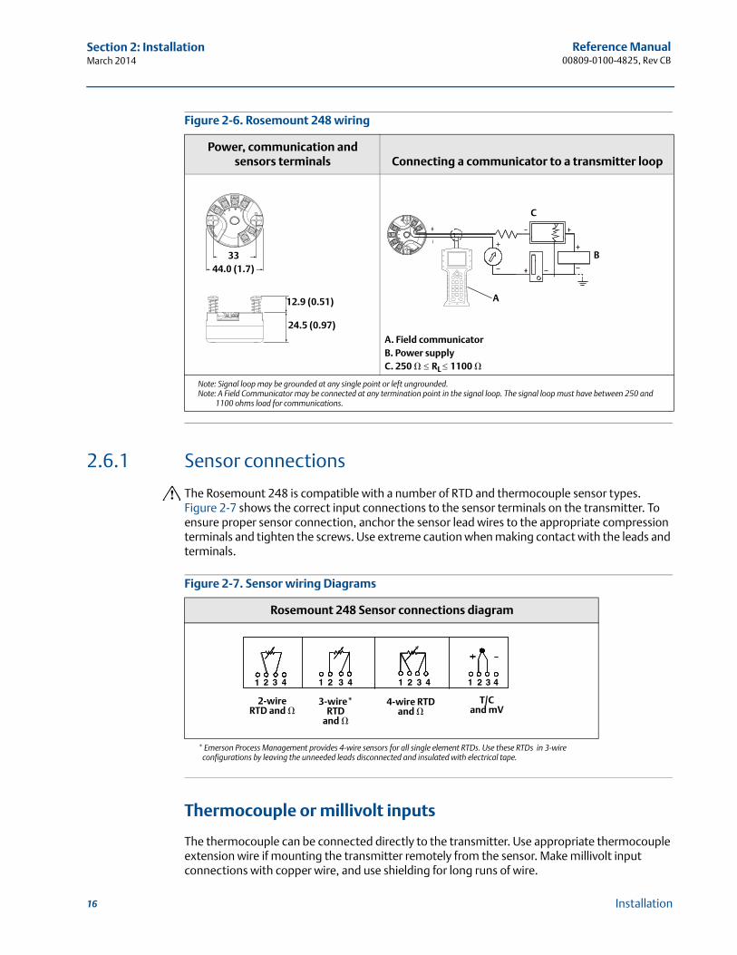
Figure 2-6. Rosemount 248 wiring
2.6.1 Sensor connections
The Rosemount 248 is compatible with a number of RTD and thermocouple sensor types. Figure 2-7 shows the correct input connections to the sensor terminals on the transmitter. To ensure proper sensor connection, anchor the sensor lead wires to the appropriate compression terminals and tighten the screws. Use extreme caution when making contact with the leads and terminals.
Figure 2-7. Sensor wiring Diagrams
Thermocouple or millivolt inputs
The thermocouple can be connected directly to the transmitter. Use appropriate thermocouple extension wire if mounting the transmitter remotely from the sensor. Make millivolt input connections with copper wire, and use shielding for long runs of wire.
Power, communication and sensors terminals Connecting a communicator to a transmitter loop
A. Field communicatorB. Power supplyC. 250 � RL 1100 �
Note: Signal loop may be grounded at any single point or left ungrounded.Note: A Field Communicator may be connected at any termination point in the signal loop. The signal loop must have between 250 and
1100 ohms load for communications.
Rosemount 248 Sensor connections diagram
* Emerson Process Management provides 4-wire sensors for all single element RTDs. Use these RTDs in 3-wire configurations by leaving the unneeded leads disconnected and insulated with electrical tape.
44.0 (1.7)33
12.9 (0.51)
24.5 (0.97)
C
B
A
1 2 3 42 3 4 1 2 3 4 1 2 3 41
2-wire RTD and �
3-wire* RTD
and �
T/C and mV
4-wire RTD and �
16 Installation
Reference Manual 00809-0100-4825, Rev CB
Section 2: InstallationMarch 2014
RTD or ohm inputs
The transmitters accepts a variety of RTD configurations, including 2-wire, 3-wire and 4-wire designs. If the transmitter is mounted remotely from a 3-wire or 4-wire RTD, it will operate within specifications, without recalibration, for lead wire resistances up to 60 ohms per lead (or the equivalent to 6,000 feet of 20 AWG wire). In this case, the leads between the RTD and transmitter should be shielded. If using only two leads, the RTD leads are in series with the sensor element, so significant errors can occur when the lead lengths exceed three feet of 20 AWG wire (approximately 0.05 °C/ft). For longer runs, attach a third or fourth lead, as described above.
Sensor lead wire resistance effect– RTD input
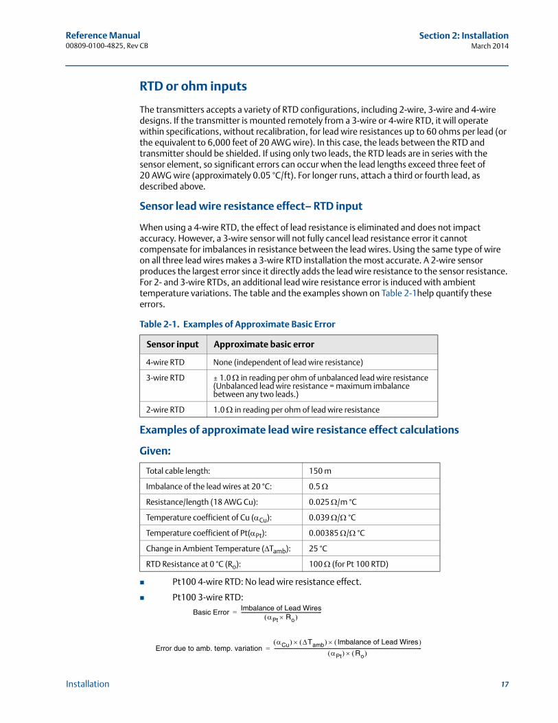
When using a 4-wire RTD, the effect of lead resistance is eliminated and does not impact accuracy. However, a 3-wire sensor will not fully cancel lead resistance error it cannot compensate for imbalances in resistance between the lead wires. Using the same type of wire on all three lead wires makes a 3-wire RTD installation the most accurate. A 2-wire sensor produces the largest error since it directly adds the lead wire resistance to the sensor resistance. For 2- and 3-wire RTDs, an additional lead wire resistance error is induced with ambient temperature variations. The table and the examples shown on Table 2-1help quantify these errors.
Table 2-1. Examples of Approximate Basic Error
Examples of approximate lead wire resistance effect calculations
Given:
Pt100 4-wire RTD: No lead wire resistance effect.
Pt100 3-wire RTD:
Sensor input Approximate basic error
4-wire RTD None (independent of lead wire resistance)
3-wire RTD ± 1.0 in reading per ohm of unbalanced lead wire resistance (Unbalanced lead wire resistance = maximum imbalance between any two leads.)
2-wire RTD 1.0 in reading per ohm of lead wire resistance
Total cable length: 150 m
Imbalance of the lead wires at 20 °C: 0.5
Resistance/length (18 AWG Cu): 0.025 /m °C
Temperature coefficient of Cu (Cu): 0.039 / °C
Temperature coefficient of Pt(Pt): 0.00385 / °C
Change in Ambient Temperature (Tamb): 25 °C
RTD Resistance at 0 °C (Ro): 100 (for Pt 100 RTD)
Basic Error Imbalance of Lead WiresPt Ro
------------------------------------------------------------------=
Error due to amb. temp. variationCu Tamb Imbalance of Lead Wires
Pt Ro -------------------------------------------------------------------------------------------------------------------------=
17Installation
Reference Manual00809-0100-4825, Rev CB
Section 2: InstallationMarch 2014
Lead wire imbalance seen by the transmitter = 0.5
Pt100 2-wire RTD:
Lead wire resistance seen by the transmitter = 150 m × 2 wires × 0.025 /m = 7.5
2.7 Power supply
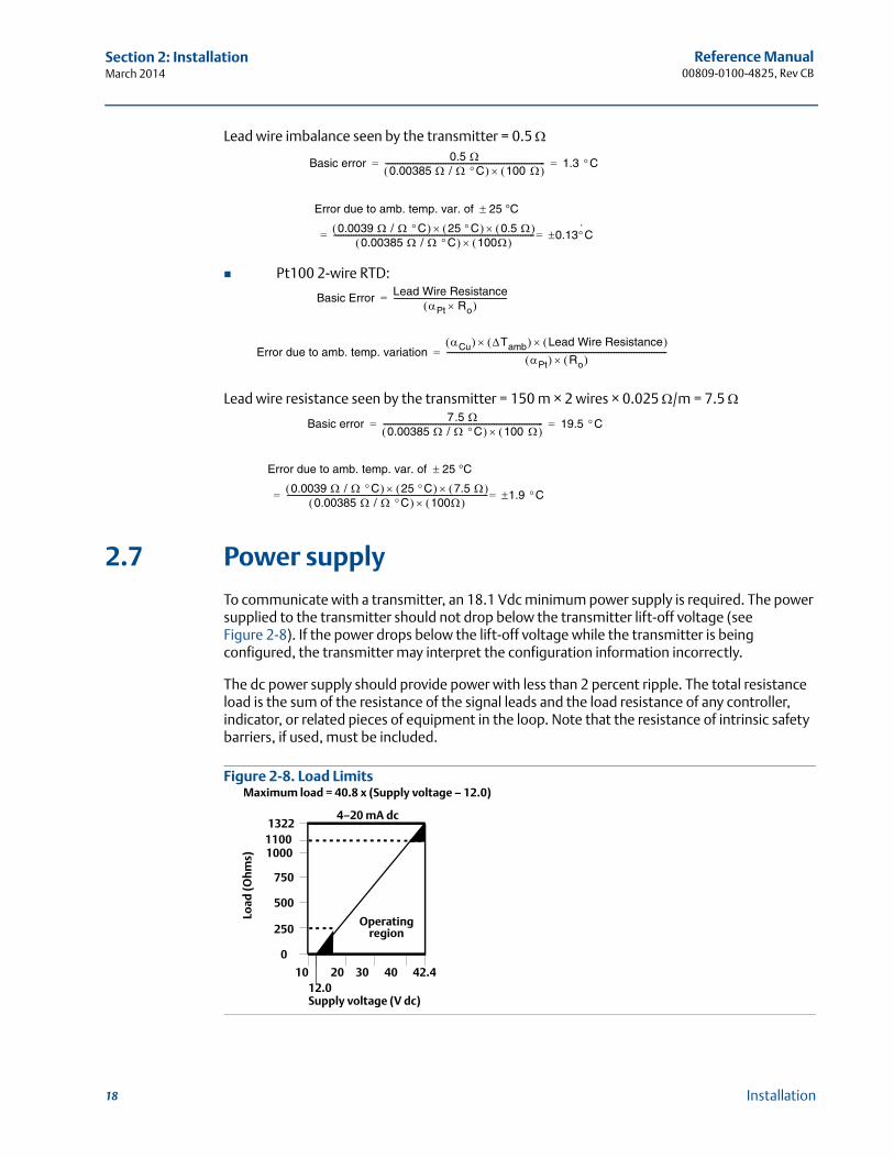
To communicate with a transmitter, an 18.1 Vdc minimum power supply is required. The power supplied to the transmitter should not drop below the transmitter lift-off voltage (see Figure 2-8). If the power drops below the lift-off voltage while the transmitter is being configured, the transmitter may interpret the configuration information incorrectly.
The dc power supply should provide power with less than 2 percent ripple. The total resistance load is the sum of the resistance of the signal leads and the load resistance of any controller, indicator, or related pieces of equipment in the loop. Note that the resistance of intrinsic safety barriers, if used, must be included.
Figure 2-8. Load Limits
Basic error 0.5 0.00385 / C 100 ---------------------------------------------------------------------------------- 1.3 C= =
Error due to amb. temp. var. of 25 °C
0.0039 / C 25 C 0.5 0.00385 / C 100
------------------------------------------------------------------------------------------------------- 0.13·C==
Basic Error Lead Wire ResistancePt Ro
----------------------------------------------------------=
Error due to amb. temp. variationCu Tamb Lead Wire Resistance
Pt Ro -----------------------------------------------------------------------------------------------------------------=
Basic error 7.5 0.00385 / C 100 ---------------------------------------------------------------------------------- 19.5 C= =
Error due to amb. temp. var. of 25 °C
0.0039 / C 25 C 7.5 0.00385 / C 100
------------------------------------------------------------------------------------------------------- 1.9 C==
4–20 mA dc1322
11001000
750
500
250
0
1012.0
20 30 40 42.4
Load
(Oh
ms)
Supply voltage (V dc)
Operating region
Maximum load = 40.8 x (Supply voltage – 12.0)
18 Installation
Reference Manual 00809-0100-4825, Rev CB
Section 2: InstallationMarch 2014
2.7.1 Surges/transients
The transmitter will withstand electrical transients of the energy level encountered in static discharges or induced switching transients. However, high-energy transients, such as those induced in wiring from nearby lightning strikes, welding, heavy electrical equipment, or switching gears, can damage both the transmitter and the sensor. To protect against high-energy transients, install the transmitter in a suitable connection head with the Rosemount 470 Transient Protector. Refer to the Rosemount 470 Transient Protector Product Data Sheet (Document No. 00813-0100-4191) for more information.
2.7.2 Ground the transmitter
The transmitter operates with the current signal loop either floating or grounded. However, extra noise in floating systems may affect many types of readout devices. If the signal appears noisy or erratic, grounding the current signal loop at a single point may solve the problem. The best place to ground the loop is at the negative terminal of the power supply. Do not ground the current signal loop at more than one point.
The transmitter is electrically isolated to 500 Vac rms (707 Vdc), so the input circuit may also be grounded at any single point. When using a grounded thermocouple, the grounded junction serves as this point.
NoteDo not ground the signal wire at both ends.
Ungrounded thermocouple, mV, and RTD/ohm inputs
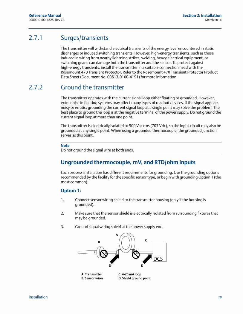
Each process installation has different requirements for grounding. Use the grounding options recommended by the facility for the specific sensor type, or begin with grounding Option 1 (the most common).
Option 1:
1. Connect sensor wiring shield to the transmitter housing (only if the housing is grounded).
2. Make sure that the sensor shield is electrically isolated from surrounding fixtures that may be grounded.
3. Ground signal wiring shield at the power supply end.
A. Transmitter C. 4-20 mA loopB. Sensor wires D. Shield ground point
CB
D D
A
19Installation
Reference Manual00809-0100-4825, Rev CB
Section 2: InstallationMarch 2014
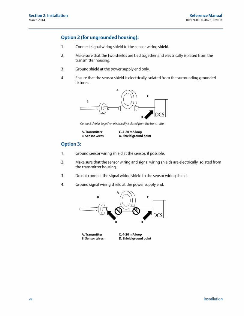
Option 2 (for ungrounded housing):
1. Connect signal wiring shield to the sensor wiring shield.
2. Make sure that the two shields are tied together and electrically isolated from the transmitter housing.
3. Ground shield at the power supply end only.
4. Ensure that the sensor shield is electrically isolated from the surrounding grounded fixtures.
Option 3:
1. Ground sensor wiring shield at the sensor, if possible.
2. Make sure that the sensor wiring and signal wiring shields are electrically isolated from the transmitter housing.
3. Do not connect the signal wiring shield to the sensor wiring shield.
4. Ground signal wiring shield at the power supply end.
A. Transmitter C. 4-20 mA loopB. Sensor wires D. Shield ground point
A. Transmitter C. 4-20 mA loopB. Sensor wires D. Shield ground point
B
C
D
Connect shields together, electrically isolated from the transmitter
A
CB
D D
A
20 Installation
Reference Manual 00809-0100-4825, Rev CB
Section 2: InstallationMarch 2014
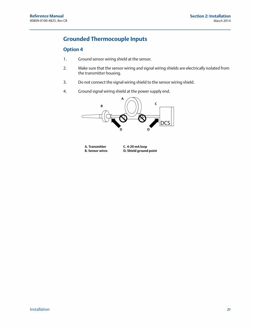
Grounded Thermocouple Inputs
Option 4
1. Ground sensor wiring shield at the sensor.
2. Make sure that the sensor wiring and signal wiring shields are electrically isolated from the transmitter housing.
3. Do not connect the signal wiring shield to the sensor wiring shield.
4. Ground signal wiring shield at the power supply end.
A. Transmitter C. 4-20 mA loopB. Sensor wires D. Shield ground point
CB
D D
A
21Installation

Reference Manual 00809-0100-4825, Rev CB
Section 3: ConfigurationMarch 2014
Section 3 Configuration
Safety messages . . . . . . . . . . . . . . . . . . . . . . . . . . . . . . . . . . . . . . . . . . . . . . . . . . . . . . . . . . . . page 23Commissioning . . . . . . . . . . . . . . . . . . . . . . . . . . . . . . . . . . . . . . . . . . . . . . . . . . . . . . . . . . . . . page 24AMS . . . . . . . . . . . . . . . . . . . . . . . . . . . . . . . . . . . . . . . . . . . . . . . . . . . . . . . . . . . . . . . . . . . . . . . page 24Field communicator . . . . . . . . . . . . . . . . . . . . . . . . . . . . . . . . . . . . . . . . . . . . . . . . . . . . . . . . . page 25Multidrop communication . . . . . . . . . . . . . . . . . . . . . . . . . . . . . . . . . . . . . . . . . . . . . . . . . . . page 39
3.1 Safety messages
Instructions and procedures in this section may require special precautions to ensure the safety of the personnel performing the operations. Information that potentially raises safety issues is indicated by a warning symbol ( ). Please refer to the following safety messages before performing an operation preceded by this symbol.
3.1.1 Warnings
Failure to follow these installation guidelines could result in death orserious injury.
Make sure only qualified personnel perform the installation.Explosions could result in death or serious injury.
Do not remove the connection head cover in explosive atmospheres when the circuit is live.
Before connecting a communicator in an explosive atmosphere, make sure the instruments in the loop are installed in accordance with instrinsically safe or non-incendive field wiring practices.
When sending or requesting data that would disrupt the loop or change the output of the transmitter, set the process application loop to manual.
Verify that the operating atmosphere of the transmitter is consistent with the appropriate hazardous locations certifications.
All connection head covers must be fully engaged to meet explosion-proof requirements.
Process leaks could result in death or serious injury.
Do not remove the thermowell while in operation. Install and tighten thermowells and sensors before applying pressureElectrical shock could cause death or serious injury.
Use extreme caution when making contact with the leads and terminals.
23Configuration
Reference Manual00809-0100-4825, Rev CB
Section 3: ConfigurationMarch 2014
3.2 Commissioning
The Rosemount 248 must be configured for certain basic variables to operate. In many cases, all of these variables are pre-configured at the factory. Configuration may be required if the transmitter is not configured or if the configuration variables need to be revised.
Commissioning consists of testing the transmitter and verifying transmitter configuration data. The Rosemount 248 can be commissioned before (off-line) or after (on-line) installation. During on-line configuration, the transmitter is connected to a Field Communicator and data is entered into the working register of the communicator and sent directly to the transmitter. Off-line configuration consists of storing configuration data in a Field Communicator while it is not connected to a transmitter. Data is stored in nonvolatile memory and can be downloaded to the transmitter at a later time. Commissioning the transmitter on the bench before installation using a Field Communicator or AMS™ Suite: Intelligent Device Manager ensures that all transmitter components are working.
To commission on the bench, connect the transmitter and the Field Communicator (or AMS) as shown in Figure 2-6 on page 16. Make sure the instruments in the loop are installed according to intrinsically-safe or non-incendive field wiring practices before connecting in an explosive atmosphere. Connect Field Communicator or AMS leads at any termination point in the signal loop. Connect the communication leads to the “COMM” terminals located on the terminal block. Do not connect to the “TEST” terminals. Then set the transmitter jumpers to avoid damage caused by the plant environment.
3.2.1 Setting the loop to manual
When sending or requesting data that could disrupt the loop or change the output of the transmitter, set the process application loop to manual. The Field Communicator will prompt to set the loop to manual when necessary. Acknowledging this prompt does not set the loop to manual, it is only a reminder. Setting the loop to manual is a separate operation.
3.3 AMS
One of the key benefits of intelligent devices is the ease of device configuration. When used with AMS, the Rosemount 248 is easily configured and provides instant and accurate alerts and alarms. The screens use a color-coding for a visual indication of the transmitter health, and to indicate any changes that may need to be made or written to the transmitter.
Gray screens: indicates that all information has been written to the transmitter
Yellow on screen: changes have been made in the software but not sent to the transmitter
Green on screen: all current changes on screen have been written to the transmitter
Red on screen: indicates an alarm or alert that requires immediate investigation
24 Configuration
Reference Manual 00809-0100-4825, Rev CB
Section 3: ConfigurationMarch 2014
3.3.1 Apply AMS changes
Right click on the device and select “Configuration Properties” from the menu.
1. From the bottom of the screen, choose Apply.
2. When an Apply Parameter Modification screen appears, enter the desired information and choose OK.
3. After reading the warning provided, choose OK.
3.4 Field communicator
The Field Communicator exchanges information with the transmitter from the control room, the instrument site, or any wiring termination point in the loop. To assist communication, connect the Field Communicator in parallel with the transmitter, as shown in Figure 2-6 on page 16. Use the loop connection ports, which are non-polarized, on the near panel of the Field Communicator. Do not make connections to the serial port of the NICAad recharger jack in explosive atmospheres. To use the Field Communicator in an explosive atmosphere, the instruments in the loop should be installed according to intrinsically safe or non-incendive field wiring practices.
When using a Field Communicator, configuration changes must be sent to the transmitter using the “Send” key (F2).
For more information regarding the Field Communicator, see the Field Communicator Reference Manual (http://www.fieldcommunicator.com/suppmanu.htm).
25Configuration
Reference Manual00809-0100-4825, Rev CB
Section 3: ConfigurationMarch 2014
put
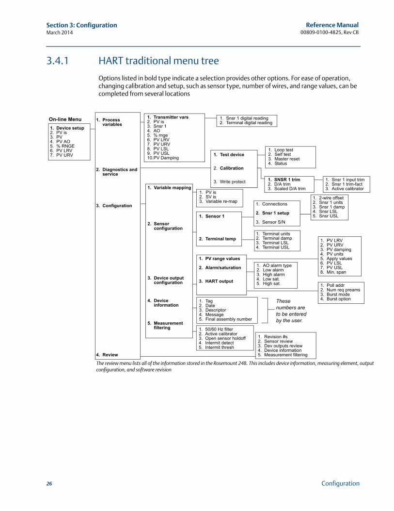
3.4.1 HART traditional menu tree
Options listed in bold type indicate a selection provides other options. For ease of operation, changing calibration and setup, such as sensor type, number of wires, and range values, can be completed from several locations
The review menu lists all of the information stored in the Rosemount 248. This includes device information, measuring element, outconfiguration, and software revision
1. Test device
2. Calibration
3. Write protect
On-line Menu 1. Snsr 1 digital reading2. Terminal digital reading
1. Snsr 1 input trim2. Snsr 1 trim-fact3. Active calibrator
1. Loop test2. Self test3. Master reset4. Status
1. SNSR 1 trim2. D/A trim3. Scaled D/A trim
1. Revision #s2. Sensor review3. Dev outputs review4. Device information5. Measurement filtering
1. Process variables
2. Diagnostics and service
3. Configuration
4. Review
1. Variable mapping
2. Sensor configuration
3. Device output configuration
4. Device information
5. Measurement filtering
1. Transmitter vars2. PV is3. Snsr 14. AO5. % rnge6. PV LRV7. PV URV8. PV LSL9. PV USL10.PV Damping
1. Device setup2. PV is3. PV 4. PV AO5. % RNGE6. PV LRV7. PV URV
1. PV is2. SV is3. Variable re-map
1. Sensor 1
2. Terminal temp
1. Connections
2. Snsr 1 setup
3. Sensor S/N
1. Terminal units2. Terminal damp3. Terminal LSL4. Terminal USL
1. PV range values
2. Alarm/saturation
3. HART output
1. AO alarm type2. Low alarm3. High alarm 4. Low sat.5. High sat. 1. Poll addr
2. Num req preams3. Burst mode4. Burst option1. Tag
2. Date3. Descriptor4. Message5. Final assembly number
1. 50/60 Hz filter2. Active calibrator3. Open sensor holdoff4. Intermit detect5. Intermit thresh
1. 2-wire offset2. Snsr 1 units3. Snsr 1 damp4. Snsr LSL5. Snsr USL
1. PV LRV2. PV URV3. PV damping4. PV units5. Apply values6. PV LSL7. PV USL8. Min. span
These numbers are to be entered by the user.
26 Configuration
Reference Manual 00809-0100-4825, Rev CB
Section 3: ConfigurationMarch 2014
27Configuration
3.4.2 HART device dashboard menu treeHome1 Overview2 Configure3 Service tools
Overview1 Device status2 Primary variable is 3 Sensor temperature 4 Analog output value 5 Upper range Value 6 Lower range value 7 Device information
Device Information1 Identification2 Revision information3 Alarm type and security
Revision Information1 HART universal2 Device3 Hardware4 Software5 Device driver
Device Status1 Active alerts Active Alerts
1 Good (only if no alerts)2 Failed (fix now)3 Maintenance
Good1 Refresh alerts2 No active alert
Failed1 Refresh alerts2 Memory failure3 Sensor error/open4 Sensor short5 Terminal temperature failure6 Electronics failure7 Invalid configuration8 Calibration failure9 Sensor degraded10 Sensor out of range11 Terminal temp out of range
Maintenance1 Refresh alerts2 Invalid configuration3 Calibration error4 Sensor degraded5 Sensor out of range6 Terminal temp out of range
Configure1 Guided setup2 Manual setup
Guided Setup1 Configure sensor 2 Calibrate sensor 3 Configure device
Sensor1 Sensor value 2 Type 3 Connection 4 Units 5 Two Wire offset 6 Damping7 Serial number8 Upper sensor limit 9 Lower sensor limit
Manual Setup1 Sensor2 Analog output3 Device 4 HART
Analog Output1 Sensor value 2 Analog output3 Percent range4 Configuration5 Alarm/Sat levels
Device 1 Identification2 Device temp units3 Open sensor hold off4 Security enable/disable5 Noise rejection
HART1 Polling address 2 Burst mode 3 Burst option
Noise Rejection1 AC oower filter2 Transient filter threshold
Alarm/Sat Levels1 High alarm level2 Low alarm level3 High sat level 4 Low sat level 5 Alarm direction
Configuration1 Primary variable is 2 Upper range value 3 Lower range value 4 Minimum span
Identification1 Tag2 Date 3 Message 4 Descriptor 5 Final assembly no.
Service Tools1 Alerts2 Variables3 Trends4 Maintenance5 Simulate
Alerts1 Refresh alerts2 No Active alerts3 Memory failure4 Sensor error/open5 Sensor short6 Terminal temp failure7 Electronics failure8 Invalid configuration9 Calibration error10 Sensor degraded11 Sensor out of range12 Terminal temp out of range
Variables1 Variable summary2 Sensor temperature (gauge)3 Terminal temperature (guage)4 Analog output (guage)
Trends1 Sensor value (trend)2 Terminal temperature (trend)
Maintenance1 Sensor calibration2 Analog trim3 Scaled trim4 Master reset
Simulate1 Loop test
Sensor Calibration1 Calibrate sensor2 Restore factory cal3 Calibration mode4 Lower cal point5 Upper cal point
Identification1 Tag2 Model3 Device ID4 Serial number5 Final assembly number6 Date7 Descriptor8 Message
Alarm type and Security1 Alarm direction 2 Security status 3 Saturation level4 Alarm level
Saturation Level1 High sat level2 Low sat level
Alarm Level1 High alarm level2 Low alarm level
Reference Manual00809-0100-4825, Rev CB
Section 3: ConfigurationMarch 2014
3.4.3 Fast Key sequence
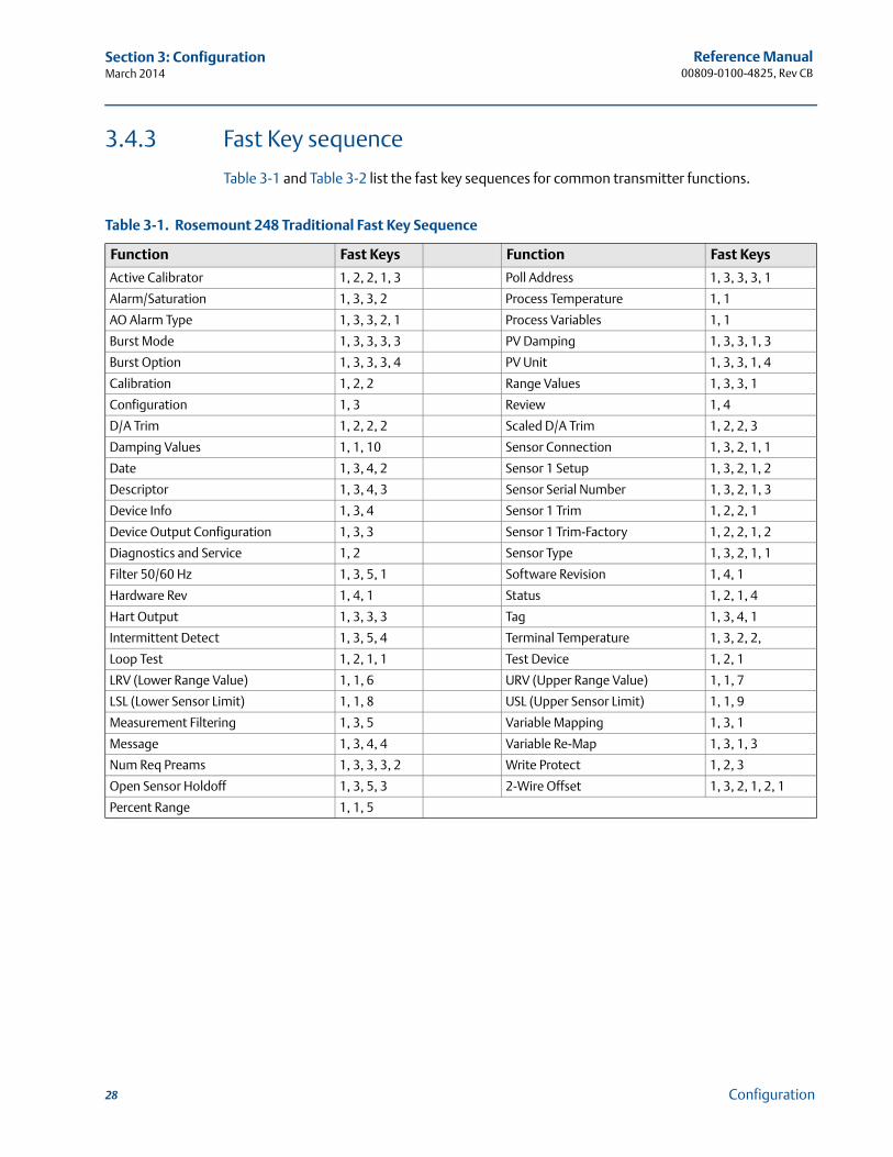
Table 3-1 and Table 3-2 list the fast key sequences for common transmitter functions.
Table 3-1. Rosemount 248 Traditional Fast Key Sequence
Function Fast Keys Function Fast Keys
Active Calibrator 1, 2, 2, 1, 3 Poll Address 1, 3, 3, 3, 1
Alarm/Saturation 1, 3, 3, 2 Process Temperature 1, 1
AO Alarm Type 1, 3, 3, 2, 1 Process Variables 1, 1
Burst Mode 1, 3, 3, 3, 3 PV Damping 1, 3, 3, 1, 3
Burst Option 1, 3, 3, 3, 4 PV Unit 1, 3, 3, 1, 4
Calibration 1, 2, 2 Range Values 1, 3, 3, 1
Configuration 1, 3 Review 1, 4
D/A Trim 1, 2, 2, 2 Scaled D/A Trim 1, 2, 2, 3
Damping Values 1, 1, 10 Sensor Connection 1, 3, 2, 1, 1
Date 1, 3, 4, 2 Sensor 1 Setup 1, 3, 2, 1, 2
Descriptor 1, 3, 4, 3 Sensor Serial Number 1, 3, 2, 1, 3
Device Info 1, 3, 4 Sensor 1 Trim 1, 2, 2, 1
Device Output Configuration 1, 3, 3 Sensor 1 Trim-Factory 1, 2, 2, 1, 2
Diagnostics and Service 1, 2 Sensor Type 1, 3, 2, 1, 1
Filter 50/60 Hz 1, 3, 5, 1 Software Revision 1, 4, 1
Hardware Rev 1, 4, 1 Status 1, 2, 1, 4
Hart Output 1, 3, 3, 3 Tag 1, 3, 4, 1
Intermittent Detect 1, 3, 5, 4 Terminal Temperature 1, 3, 2, 2,
Loop Test 1, 2, 1, 1 Test Device 1, 2, 1
LRV (Lower Range Value) 1, 1, 6 URV (Upper Range Value) 1, 1, 7
LSL (Lower Sensor Limit) 1, 1, 8 USL (Upper Sensor Limit) 1, 1, 9
Measurement Filtering 1, 3, 5 Variable Mapping 1, 3, 1
Message 1, 3, 4, 4 Variable Re-Map 1, 3, 1, 3
Num Req Preams 1, 3, 3, 3, 2 Write Protect 1, 2, 3
Open Sensor Holdoff 1, 3, 5, 3 2-Wire Offset 1, 3, 2, 1, 2, 1
Percent Range 1, 1, 5
28 Configuration
Reference Manual 00809-0100-4825, Rev CB
Section 3: ConfigurationMarch 2014
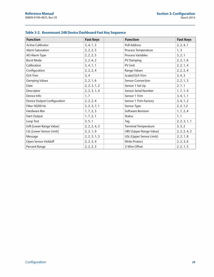
Table 3-2. Rosemount 248 Device Dashboard Fast Key Sequence
Function Fast Keys Function Fast Keys
Active Calibrator 3, 4, 1, 3 Poll Address 2, 2, 4, 1
Alarm Saturation 2, 2, 2, 5 Process Temperature 1, 3
AO Alarm Type 2, 2, 2, 5 Process Variables 3, 2, 1
Burst Mode 2, 2, 4, 2 PV Damping 2, 2, 1, 6
Calibration 3, 4, 1, 1 PV Unit 2, 2, 1, 4
Configuration 2, 2, 2, 4 Range Values 2, 2, 2, 4
D/A Trim 3, 4 Scaled D/A Trim 3, 4, 3
Damping Values 2, 2, 1, 6 Sensor Connection 2, 2, 1, 3
Date 2, 2, 3, 1, 2 Sensor 1 Set Up 2, 1, 1
Descriptor 2, 2, 3, 1, 4 Sensor Serial Number 1, 7, 1, 4
Device Info 1, 7 Sensor 1 Trim 3, 4, 1, 1
Device Output Configuration 2, 2, 2, 4 Sensor 1 Trim-Factory 3, 4, 1, 2
Filter 50/60 Hz 2, 2, 3, 7, 1 Sensor Type 2, 2, 1,2
Hardware Rev 1, 7, 2, 3 Software Revision 1, 7, 2, 4
Hart Output 1, 7, 2, 1 Status 1, 1
Loop Test 3, 5, 1 Tag 2, 2, 3, 1, 1
LVR (Lower Range Value) 2, 2, 2, 4, 3 Terminal Temperature 3, 3, 2
LSL (Lower Sensor Limit) 2, 2, 1, 9 URV (Upper Range Value) 2, 2, 2, 4, 2
Message 2, 2, 3, 1, 3 USL (Upper Sensor Limit) 2, 2, 1, 8
Open Sensor Holdoff 2, 2, 3, 4 Write Protect 2, 2, 3, 6
Percent Range 2, 2, 2, 3 2-Wire Offset 2, 2, 1, 5
29Configuration
Reference Manual00809-0100-4825, Rev CB
Section 3: ConfigurationMarch 2014
3.4.4 Review configuration data
Before operating the Rosemount 248 in an actual installation, review all of the factory-set configuration data to be sure that it reflects the current application.
Review
When activating the Review function, scroll through the configuration data list to check each process variable. If changes to the transmitter configuration data are necessary, refer to “Config-uration” below.
3.4.5 Check output
Before performing other transmitter on-line operations, review the Rosemount 248 digital output parameters to be sure that the transmitter is operating properly.
Process variables
The Process Variables menu displays continuously updated process variables, including sensor temperature, percent of range, analog output, and terminal temperature. The primary variable is the 4 –20 mA analog signal. The secondary variable is the transmitter terminal temperature.
3.4.6 Configuration
The Rosemount 248 must be configured for certain basic variables to be operational. In many cases, these variables are pre-configured at the factory. Configuration may be required if the transmitter is not configured, or if the configuration variables need revision.
Variable mapping
The Variable Mapping menu displays the sequence of the process variables. When using the Rosemount 248 5 Variable Re-Map can be selected to change this configuration. When the Select PV screen appears Snsr 1 must be selected. Either Sensor 1, Terminal Temperature, or not used can be selected for the remaining variables. The primary variable is the 4–20 mA analog signal.
Fast Key sequence 1, 4
Fast Key sequence 1, 1
Fast Key sequence 1, 3, 1
30 Configuration
Reference Manual 00809-0100-4825, Rev CB
Section 3: ConfigurationMarch 2014
Select sensor type
The Connections command allows selection of the sensor type and the number of sensor wires to be connected. Select from the following sensors:
2-, 3-, or 4-wire Pt 100, Pt 200, Pt 500, Pt 1000 RTDs: = 0.00385 /°C
2-, 3-, or 4-wire Pt 100: = 0.003916 /°C
2-, 3-, or 4-wire Ni 120 nickel RTDs
2-, 3-, or 4-wire Cu 10 RTDs
IEC/NIST/DIN Type B, E, J, K, R, S, T thermocouples
DIN type L, U thermocouples
ASTM Type W5Re/W26Re thermocouple
–10 to 100 millivolts
2-, 3-, or 4-wire 0 to 2000 ohms
A complete line of temperature sensors, thermowells, and accessory mounting hardware is available from Emerson Process Management.
Set output units
The Set Output Unit command establishes the desired primary variable units. The transmitter output can be set to one of the following engineering units:
Degrees Celsius
Degrees Fahrenheit
Degrees Rankine
Kelvin
Ohms
Millivolts
50/60 Hz filter
The 50/60 Hz Filter command sets the transmitter electronic filter to reject the AC power supply frequency in the plant.
Terminal temperature
The Terminal Temp command sets the terminal temperature units to indicate the temperature at the transmitter terminals.
Fast Key sequence 1, 3, 2, 1, 1
Fast Key sequence 1, 3, 2, 1, 2, 2
Fast Key sequence 1, 3, 5, 1
Fast Key sequence 1, 3, 2, 2
31Configuration
Reference Manual00809-0100-4825, Rev CB
Section 3: ConfigurationMarch 2014
Process Variable (PV) damping
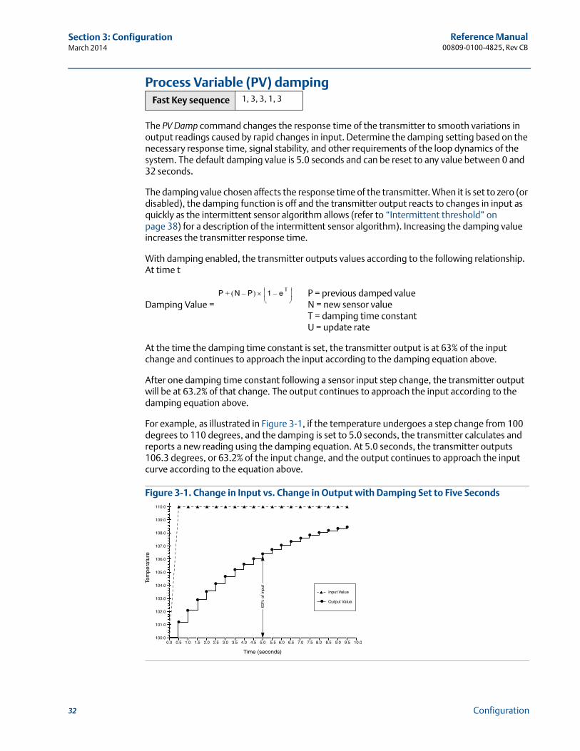
The PV Damp command changes the response time of the transmitter to smooth variations in output readings caused by rapid changes in input. Determine the damping setting based on the necessary response time, signal stability, and other requirements of the loop dynamics of the system. The default damping value is 5.0 seconds and can be reset to any value between 0 and 32 seconds.
The damping value chosen affects the response time of the transmitter. When it is set to zero (or disabled), the damping function is off and the transmitter output reacts to changes in input as quickly as the intermittent sensor algorithm allows (refer to “Intermittent threshold” on page 38) for a description of the intermittent sensor algorithm). Increasing the damping value increases the transmitter response time.
With damping enabled, the transmitter outputs values according to the following relationship. At time t
Damping Value =
At the time the damping time constant is set, the transmitter output is at 63% of the input change and continues to approach the input according to the damping equation above.
After one damping time constant following a sensor input step change, the transmitter output will be at 63.2% of that change. The output continues to approach the input according to the damping equation above.
For example, as illustrated in Figure 3-1, if the temperature undergoes a step change from 100 degrees to 110 degrees, and the damping is set to 5.0 seconds, the transmitter calculates and reports a new reading using the damping equation. At 5.0 seconds, the transmitter outputs 106.3 degrees, or 63.2% of the input change, and the output continues to approach the input curve according to the equation above.
Figure 3-1. Change in Input vs. Change in Output with Damping Set to Five Seconds
Fast Key sequence 1, 3, 3, 1, 3
P N P– 1 eT
–
+ P = previous damped valueN = new sensor valueT = damping time constantU = update rate
32 Configuration
Reference Manual 00809-0100-4825, Rev CB
Section 3: ConfigurationMarch 2014
2-Wire RTD offset
The 2-Wire RTD Offset command allows the user to input the measured lead wire resistance, which results in the transmitter adjusting its temperature measurement to correct the error caused by this resistance. Due to a lack of lead wire compensation within the RTD, temperature measurements made with a 2-wire RTD are often inaccurate. See “Sensor lead wire resistance effect– RTD input” on page 17 for more information.
To utilize this feature:
1. Measure the lead wire resistance of both RTD leads after installing the 2-wire RTD and the Rosemount 248.
2. From the HOME screen, select 1 Device Setup, 3 Configuration, 2 Sensor Configuration, 1 Sensor 1, 2 Snsr 1 Setup, and 1 2-Wire Offset.
3. Enter the total measured resistance of the two RTD leads at the 2-Wire Offset prompt. Enter this resistance as a negative (–) value to ensure proper adjustment.The transmitter adjusts its temperature measurement to correct the error caused by lead wire resistance.
3.4.7 Information variables
Access the transmitter information variables on-line using the Field Communicator or other suitable communications device. Following is a list of transmitter information variables which include device identifiers, factory-set configuration variables, and other information. A description of each variable, the corresponding fast key sequence, and a review of its purposes are provided.
Tag
The Tag variable is the easiest way to identify and distinguish between transmitters in multi-transmitter environments. Use it to label transmitters electronically according to the requirements of the application. The tag defined is automatically displayed when a 375 Field Communicator establishes contact with the transmitter at power-up. The tag may be up to eight characters long and has no impact on the primary variable readings of the transmitter.
Date
The Date command is a user-defined variable that provides a place to save the date of the last revision of configuration information. It has no impact on the operation of the transmitter or the Field Communicator.
Fast Key sequence 1, 3, 2, 1, 2, 1
Fast Key sequence 1, 3, 4, 1
Fast Key sequence 1, 3, 4, 2
33Configuration
Reference Manual00809-0100-4825, Rev CB
Section 3: ConfigurationMarch 2014
Descriptor
The Descriptor variable provides a longer user-defined electronic label to assist with more specific transmitter identification than is available with the tag variable. The descriptor may be up to 16 characters long and has no impact on the operation of the transmitter or the Field Communicator.
Message
The Message variable provides the most specific user-defined means for identifying individual transmitters in multi-transmitter environments. It allows for 32 characters of information and is stored with the other configuration data. The message variable has no impact on the operation of the transmitter or the Field Communicator.
Sensor serial number
The Sensor S/N variable provides a location to list the serial number of the attached sensor. It is useful for identifying sensors and tracking sensor calibration information.
3.4.8 Diagnostics and service
Test device
The Test Device command initiates a more extensive diagnostics routine than is performed continuously by the transmitter. The Test Device menu lists the following options:
1 Loop test verifies the output of the transmitter, the integrity of the loop, and the operations of any recorders or similar devices installed in the loop. See “Loop test” below for more information.
2 Self Test initiates a transmitter self test. Error codes are displayed if there is a problem.
3 Master Reset sends out a command that restarts and tests the transmitter. A master reset is like briefly powering down the transmitter. Configuration data remains unchanged after a master reset.
4 Status lists error codes. ON indicates a problem, and OFF means there are no problems.
Loop test
The Loop Test command verifies the output of the transmitter, the integrity of the loop, and the operations of any recorders or similar devices installed in the loop. To initiate a loop test, perform the following procedure:
Fast Key sequence 1, 3, 4, 3
Fast Key sequence 1, 3, 4, 4
Fast Key sequence 1, 3, 2, 1, 4
Fast Key sequence 1, 2, 1
Fast Key sequence 1, 2, 1, 1
34 Configuration
Reference Manual 00809-0100-4825, Rev CB
Section 3: ConfigurationMarch 2014
1. Connect a reference meter to the transmitter. To do so, shuntthe transmitter power through the meter at some point in the loop.
2. From the HOME screen, choose 1 Device Setup, 2 Diag/Serv, 1 Test Device, 1 Loop Test before performing a loop test.
3. Choose a discreet milliampere level for the transmitter to output. At the CHOOSE ANALOG OUTPUT prompt, choose 1 4mA, 2 20mA, or choose 3 other to manually input a value between 4 and 20 mA.
4. Check the current meter installed in the test loop to verify that it reads the value that was commanded to output. If the readings do not match, either the transmitter requires an output trim or the current meter is malfunctioning.
After completing the test procedure, the display returns to the loop test screen and another output value can be chosen.
Master reset
Master Reset resets the electronics without actually powering down the unit. It does not return the transmitter to the original factory configuration.
Active calibrator
The Active Calibrator Mode command enables or disables the pulsating current feature. The transmitter ordinarily operates with pulsating current so that sensor diagnostic functions, such as open sensor detection and EMF compensation, can be performed correctly. Some calibration equipment requires steady current to function properly. By enabling the Active Calibrator Mode the transmitter stops sending pulsating current to the sensor and supplies a steady current. Disabling the Active Calibrator returns the transmitter to the normal operating state where it sends a pulsating current to the sensor, enabling the sensor diagnostic functions.
The Active Calibrator Mode is volatile and is automatically disabled when power is cycled, or when a Master Reset is performed using the Field Communicator.
NoteThe Active Calibrator Mode must be disabled before returning the transmitter to the process to ensure that the full diagnostic capabilities of the Rosemount 248 are available.
Disabling or enabling the Active Calibrator Mode will not change any of the sensor trim values stored in the transmitter.
Sensor review
The Signal Condition command allows viewing or changing of the primary variable lower and upper range values, sensor percent of range, and sensor damping.
Fast Key sequence 1, 2, 1, 3
Fast Key sequence 1, 2, 2, 1, 3
Fast Key sequence 1, 4, 2
35Configuration
Reference Manual00809-0100-4825, Rev CB
Section 3: ConfigurationMarch 2014
Write protect
The Write Protect command protects the transmitter configuration data from accidental or unwarranted changes. To enable the write protect feature:
1. From the HOME screen choose 1 Device Setup, 2 Diag/Service, 3 Write Protect.
2. Choose Enable WP.
NoteTo disable write protect on the Rosemount 248, repeat the procedure, replacing Enable WP with Disable WP.
HART output
The HART Output command allows the user to make changes to the multidrop address, initiate burst mode, or make changes to the burst options.
Alarm and saturation
The Alarm/Saturation command allows the alarm settings (Hi or Low) and saturation values to be viewed and changed. To change the alarm values and saturation values, select the value to be changed, either 2 Low Alarm, 3 High Alarm, 4 Low Sat., or 5 High Sat then enter the desired new value, which must fall within the guidelines:
The low alarm value must be between 3.50 and 3.75 mA
The high alarm value must be between 21.0 and 23.0 mA
The low saturation level must be between the low alarm value plus 0.1 mA and 3.9 mA.
Example: The low alarm value has been set to 3.7 mA. Therefore, the low saturation level, S, must be 3.8 S 3.9 mA.
The high saturation level must be between 20.5 mA and the high alarm value minus 0.1 mA.
Example: The high alarm value has been set to 20.8 mA. Therefore, the low saturation level, S, must be 20.5 S 20.7 mA.
See “Failure mode” on page 14 for Failure Mode considerations.
Rerange
Reranging the transmitter sets the measurement range to the limits of expected readings which maximizes transmitter performance; the readings are is most accurate when the transmitter is operated within the expected temperature range for the application.
Fast Key sequence 1, 2, 3
Fast Key sequence 1, 3, 3, 3
Fast Key sequence 1, 3, 3, 2
36 Configuration
Reference Manual 00809-0100-4825, Rev CB
Section 3: ConfigurationMarch 2014
PV range values
The PV URV and PV LRV commands, found on the PV Range Values menu screen, allow the user to set the transmitter’s lower and upper range values using limits of expected readings. The range of expected readings is defined by the Lower Range Value (LRV) and Upper Range Value (URV). The transmitter range values can be reset as often as necessary to reflect changing process conditions. From the PV Range Values screen select 1 PV LRV to change the lower range value and 2 PV URV to change the upper range value.
Note: The rerange functions should not be confused with the trim functions. Although the rerange command matches a sensor input to a 4–20 mA output, as in conventional calibration, it does not affect the transmitter’s interpretation of the input.
Intermittent sensor detect (advanced feature)
The Intermittent Sensor Detect feature guards against process temperature readings caused by intermittent open sensor conditions (an intermittent sensor condition is an open sensor condition that lasts less than one update). By default, the transmitter is shipped with the Intermittent Sensor Detect feature switched ON and the threshold value set to 0.2% of sensor limits. The Intermittent Sensor Detect feature can be switched ON or OFF and the threshold value can be changed to any value between 0 and 100% of the sensor limits with a Field Communicator.
Transmitter behavior with intermittent sensor detect ON
When the Intermittent Sensor Detect feature is switched ON, the transmitter can eliminate the output pulse caused by intermittent open sensor conditions. Process temperature changes (T) within the threshold value are tracked normally by the transmitter’s output. A T greater than the threshold value activates the intermittent sensor algorithm. True open sensor conditions cause the transmitter to go into alarm.
The threshold value of the Rosemount 248 should be set at a level allowing for normal range of process temperature fluctuations; too high and the algorithm will not be able to filter out intermittent conditions; too low and the algorithm will be activated unnecessarily. The default threshold value is 0.2% of the sensor limits.
Transmitter behavior with intermittent sensor detect OFF
When the Intermittent Sensor Detect feature is switched OFF, the transmitter tracks all process temperature changes, even if they are the result of an intermittent sensor. (The transmitter behaves as though the threshold value had been set at 100%.) The output delay because of the intermittent sensor algorithm will be eliminated.
Fast Key sequencePV URV = 6PV LRV = 7
37Configuration
Reference Manual00809-0100-4825, Rev CB
Section 3: ConfigurationMarch 2014
Intermittent threshold
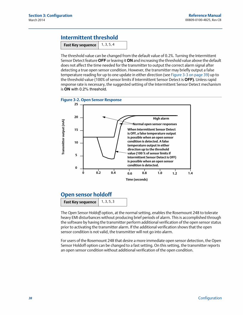
The threshold value can be changed from the default value of 0.2%. Turning the Intermittent Sensor Detect feature OFF or leaving it ON and increasing the threshold value above the default does not affect the time needed for the transmitter to output the correct alarm signal after detecting a true open sensor condition. However, the transmitter may briefly output a false temperature reading for up to one update in either direction (see Figure 3-3 on page 39) up to the threshold value (100% of sensor limits if Intermittent Sensor Detect is OFF). Unless rapid response rate is necessary, the suggested setting of the Intermittent Sensor Detect mechanism is ON with 0.2% threshold.
Figure 3-2. Open Sensor Response
Open sensor holdoff
The Open Sensor Holdoff option, at the normal setting, enables the Rosemount 248 to tolerate heavy EMI disturbances without producing brief periods of alarm. This is accomplished through the software by having the transmitter perform additional verification of the open sensor status prior to activating the transmitter alarm. If the additional verification shows that the open sensor condition is not valid, the transmitter will not go into alarm.
For users of the Rosemount 248 that desire a more immediate open sensor detection, the Open Sensor Holdoff option can be changed to a fast setting. On this setting, the transmitter reports an open sensor condition without additional verification of the open condition.
Fast Key sequence 1, 3, 5, 4
Fast Key sequence 1, 3, 5, 3
0
0
5
10
15
20
25
0.2 0.4 0.6 0.8 1.0 1.2 1.4
Tran
smit
ter
ou
tpu
t (m
A)
Time (seconds)
When Intermittent Sensor Detect is OFF, a false temperature output is possible when an open sensor condition is detected. A false temperature output in either direction up to the threshold value (100 % of sensor limits if Intermittent Sensor Detect is OFF) is possible when an open sensor condition is detected.
Normal open sensor responses
High alarm
38 Configuration
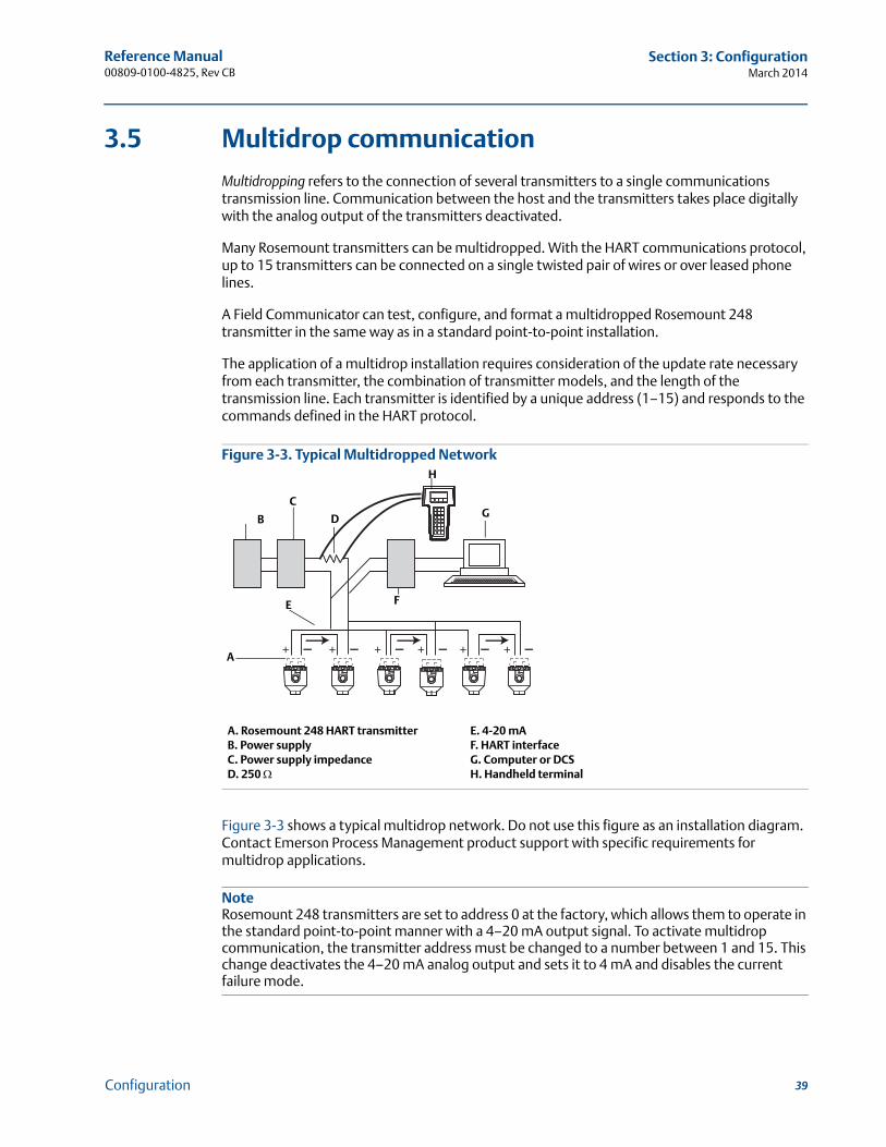
Reference Manual 00809-0100-4825, Rev CB
Section 3: ConfigurationMarch 2014
3.5 Multidrop communication
Multidropping refers to the connection of several transmitters to a single communications transmission line. Communication between the host and the transmitters takes place digitally with the analog output of the transmitters deactivated.
Many Rosemount transmitters can be multidropped. With the HART communications protocol, up to 15 transmitters can be connected on a single twisted pair of wires or over leased phone lines.
A Field Communicator can test, configure, and format a multidropped Rosemount 248 transmitter in the same way as in a standard point-to-point installation.
The application of a multidrop installation requires consideration of the update rate necessary from each transmitter, the combination of transmitter models, and the length of the transmission line. Each transmitter is identified by a unique address (1–15) and responds to the commands defined in the HART protocol.
Figure 3-3. Typical Multidropped Network
Figure 3-3 shows a typical multidrop network. Do not use this figure as an installation diagram. Contact Emerson Process Management product support with specific requirements for multidrop applications.
NoteRosemount 248 transmitters are set to address 0 at the factory, which allows them to operate in the standard point-to-point manner with a 4–20 mA output signal. To activate multidrop communication, the transmitter address must be changed to a number between 1 and 15. This change deactivates the 4–20 mA analog output and sets it to 4 mA and disables the current failure mode.
A. Rosemount 248 HART transmitter E. 4-20 mAB. Power supply F. HART interfaceC. Power supply impedance G. Computer or DCSD. 250 H. Handheld terminal
B
C
H
G
A
E F
D
39Configuration
Reference Manual00809-0100-4825, Rev CB
Section 3: ConfigurationMarch 2014
3.6 Rosemount 248 Configuration Interface specifications
3.6.1 Configuration software
The 248 PC-based configuration software for the Rosemount 248 allows comprehensive configuration of the transmitters. Used in conjunction with various Rosemount or user-supplied hardware modems, the software provides the tools necessary to configure the Rosemount 248 transmitters including the following parameters:
Process Variable
Sensor Type
Number of Wires
Engineering Units
Transmitter Tag Information
Damping
Alarming Parameters
3.6.2 Configuration hardware
The 248 Configuration Interface has three hardware options as follows:
Software only
Customer must provide appropriate communications hardware (modem, power supply, etc.)
Serial HART modem and software
Serial HART modem. Customer must provide separate loop power supply and resistor. Requires PC serial port. Suitable for use with powered loops.
USB HART modem and software
USB (Universal Serial Bus) HART modem. Customer must provide separate loop power supply and resistor. Requires PC with USB port. Suitable for use with powered loops.
40 Configuration
Reference Manual 00809-0100-4825, Rev CB
Section 3: ConfigurationMarch 2014
3.6.3 Rosemount 248 PC Programmer Kit installation
1. Install all necessary software for Rosemount 248 PC configuration:
a. Install the Rosemount 248C software
– Place the 248C CD-ROM in the drive
– Run setup.exe from Windows NT, 2000, or XP
b. Install the MACTek HART Modem drivers completely before beginning bench configuration with the Rosemount 248 PC Programming system.
NoteFor USB modem: Upon first use, configure appropriate COM ports within the Rosemount 248PC software by choosing Port Settings from the Communicate menu. The USB modem driver emulates a COM port and will add to available port selections in the software’s drop-down box. Otherwise software defaults to first available COM port, which may not be correct.
2. Set up configuration system hardware:
a. Hook up the transmitter and load resistor (250-1100 ohms) wired in series with the power supply. (The Rosemount 248 device will need an external power supply of 12-42.4 Vdc for configuration)
b. Attach the HART Modem in parallel with the load resistor and connect it to the PC
Please see Table 3-3 for spares kit and re-order numbers.
Table 3-3. Rosemount 248 Programming Kit Spare Part Numbers
Product description Part number
Programming Software (CD) 00248-1603-0002
Rosemount 248 Programmer Kit - USB 00248-1603-0003
Rosemount 248 Programmer Kit - Serial 00248-1603-0004
41Configuration


Reference Manual 00809-0100-4825, Rev CB
Section 4: Operation and MaintenanceMarch 2014
Section 4 Operation and maintenance
Safety messages . . . . . . . . . . . . . . . . . . . . . . . . . . . . . . . . . . . . . . . . . . . . . . . . . . . . . . . . . . . . page 43Calibration . . . . . . . . . . . . . . . . . . . . . . . . . . . . . . . . . . . . . . . . . . . . . . . . . . . . . . . . . . . . . . . . . page 44Hardware . . . . . . . . . . . . . . . . . . . . . . . . . . . . . . . . . . . . . . . . . . . . . . . . . . . . . . . . . . . . . . . . . . page 46Diagnostic messages . . . . . . . . . . . . . . . . . . . . . . . . . . . . . . . . . . . . . . . . . . . . . . . . . . . . . . . . page 47
4.1 Safety messages
Instructions and procedures in this section may require special precautions to ensure the safety of the personnel performing the operations. Information that potentially raises safety issues is indicated by a warning symbol ( ). Please refer to the following safety messages before performing an operation preceded by this symbol.
4.1.1 Warnings
Failure to follow these installation guidelines could result in death orserious injury.
Make sure only qualified personnel perform the installation.Explosions could result in death or serious injury.
Do not remove the connection head cover in explosive atmospheres when the circuit is live.
Before connecting a Field Communicator in an explosive atmosphere, make sure the instruments in the loop are installed in accordance with intrinsically safe or non-incendive field wiring practices.
When sending or requesting data that would disrupt the loop or change the output of the transmitter, set the process application loop to manual.
Verify that the operating atmosphere of the transmitter is consistent with the appropriate hazardous locations certifications.
All connection head covers must be fully engaged to meet explosion-proof requirements.
Process leaks could result in death or serious injury.
Do not remove the thermowell while in operation. Install and tighten thermowells and sensors before applying pressureElectrical shock could cause death or serious injury.
Use extreme caution when making contact with the leads and terminals.
43Operation and Maintenance
Reference Manual00809-0100-4825, Rev CB
Section 4: Operation and MaintenanceMarch 2014
4.2 Calibration
Calibrating the transmitter increases measurement precision by allowing corrections to be made to the factory-stored characterization curve by digitally altering the transmitter’s interpretation of the sensor input.
To understand calibration, it is necessary to realize that smart transmitters operate differently from analog transmitters. An important difference being that smart transmitters are fac-tory-characterized, meaning they are shipped with a standard sensor curve stored in the transmitter firmware. In operation, the transmitter uses this information to produce a process variable output, in engineering units, dependent on the sensor input.
Calibration of the Rosemount 248 may include the following procedures:
Sensor Input Trim: digitally alter the transmitter’s interpretation of the input signal
Output Trim: calibrates the transmitter to a 4–20 mA reference scale
Scaled Output Trim: calibrates the transmitter to a user-selectable reference scale.
4.2.1 Trim the transmitter
One or more of the trim functions may be used when calibrating. The trim functions are as follows
Sensor Input Trim
Output Trim
Output Scaled Trim
Sensor input trim
Perform a sensor trim if the transmitters digital value for the primary variable does not match the plant’s standard calibration equipment. The sensor trim function calibrates the sensor to the transmitter in temperature units or raw units. Unless your site-standard input source is NIST-traceable, the trim functions will not maintain the NIST-traceability of the system.
The Sensor Input Trim command allows the transmitter’s interpretation of the input signal to be digitally altered (see <HotXRef>Figure 4-1). The sensor input calibration trims the combined sensor and transmitter system to a site standard using a known temperature source. Sensor trimming is suitable for validation procedures or for applications that require calibrating the sensor and transmitter together.
Fast Key sequence 1, 2, 2, 1, 1
44 Operation and Maintenance
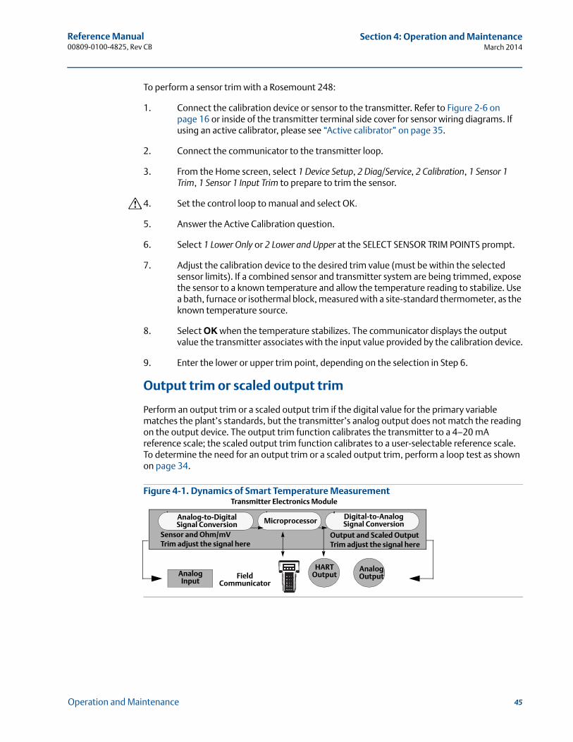
Reference Manual 00809-0100-4825, Rev CB
Section 4: Operation and MaintenanceMarch 2014
To perform a sensor trim with a Rosemount 248:
1. Connect the calibration device or sensor to the transmitter. Refer to Figure 2-6 on page 16 or inside of the transmitter terminal side cover for sensor wiring diagrams. If using an active calibrator, please see “Active calibrator” on page 35.
2. Connect the communicator to the transmitter loop.
3. From the Home screen, select 1 Device Setup, 2 Diag/Service, 2 Calibration, 1 Sensor 1 Trim, 1 Sensor 1 Input Trim to prepare to trim the sensor.
4. Set the control loop to manual and select OK.
5. Answer the Active Calibration question.
6. Select 1 Lower Only or 2 Lower and Upper at the SELECT SENSOR TRIM POINTS prompt.
7. Adjust the calibration device to the desired trim value (must be within the selected sensor limits). If a combined sensor and transmitter system are being trimmed, expose the sensor to a known temperature and allow the temperature reading to stabilize. Use a bath, furnace or isothermal block, measured with a site-standard thermometer, as the known temperature source.
8. Select OK when the temperature stabilizes. The communicator displays the output value the transmitter associates with the input value provided by the calibration device.
9. Enter the lower or upper trim point, depending on the selection in Step 6.
Output trim or scaled output trim
Perform an output trim or a scaled output trim if the digital value for the primary variable matches the plant’s standards, but the transmitter’s analog output does not match the reading on the output device. The output trim function calibrates the transmitter to a 4–20 mA reference scale; the scaled output trim function calibrates to a user-selectable reference scale. To determine the need for an output trim or a scaled output trim, perform a loop test as shown on page 34.
Figure 4-1. Dynamics of Smart Temperature Measurement
Microprocessor Digital-to-Analog Signal Conversion
Analog-to-Digital Signal Conversion
Transmitter Electronics Module
Analog Input
Analog Output Field
Communicator
HARTOutput
Sensor and Ohm/mV Trim adjust the signal here
Output and Scaled Output Trim adjust the signal here
45Operation and Maintenance
Reference Manual00809-0100-4825, Rev CB
Section 4: Operation and MaintenanceMarch 2014
Output trim
The D/A Trim command allows the transmitter’s conversion of the input signal to a 4–20 mA output to be altered (see Figure 4-1 on page 45). Adjust the analog output signal at regular intervals to maintain measurement precision. To perform a digital-to-analog trim:
1. From the HOME screen, select 1 Device setup, 2 Diag/Service, 2 Calibration, 2 D/A trim. Set the control loop to manual and select OK.
2. Connect an accurate reference meter to the transmitter at the CONNECT REFERENCE METER prompt by shunting the power to the transmitter through the reference meter at some point in the loop. Select OK after connecting the reference meter.
3. Select OK at the SETTING FLD DEV OUTPUT TO 4 MA prompt, then transmitter outputs 4.00 mA.
4. Record the actual value from the reference meter, and enter it at the ENTER METER VALUE prompt. The communicator prompts the user to verify whether or not the output value equals the value on the reference meter.
5. If the reference meter value equals the transmitter output value, select 1 Yes and go to Step 6. If the reference meter value is not equal to the transmitter output value, select 2 No and go to Step 4.
6. Select OK at the SETTING FLD DEV OUTPUT TO 20 MA prompt and repeat steps 4 and 5 until the reference meter value equals the transmitter output value.
7. Return the control loop to automatic control and select OK.
Scaled output trim
The Scaled D/A Trim command matches the 4 and 20 mA points to a user-selectable reference scale other than 4 and 20 mA (2–10 volts, for example). To perform a scaled D/A trim, connect an accurate reference meter to the transmitter and trim the output signal to scale as outlined in the Output trim procedure.
4.3 Hardware
4.3.1 Maintenance
The Rosemount 248 has no moving parts and requires minimal scheduled maintenance.
Sensor checkout
To determine whether the sensor is at fault, replace it with another sensor or connect a test sensor locally at the transmitter to test remote sensor wiring. Do not remove the thermowell while in operation. Select any standard, off-the-shelf sensor for use with a Rosemount 248, or consult the factory for a replacement special sensor and transmitter combination.
Fast Key sequence 1, 2, 2, 2
Fast Key sequence 1, 2, 2, 3
46 Operation and Maintenance
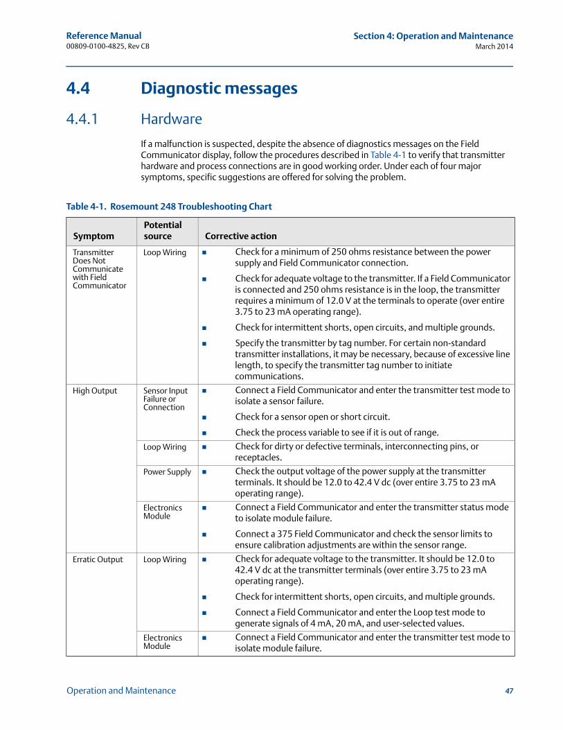
Reference Manual 00809-0100-4825, Rev CB
Section 4: Operation and MaintenanceMarch 2014
4.4 Diagnostic messages
4.4.1 Hardware
If a malfunction is suspected, despite the absence of diagnostics messages on the Field Communicator display, follow the procedures described in Table 4-1 to verify that transmitter hardware and process connections are in good working order. Under each of four major symptoms, specific suggestions are offered for solving the problem.
Table 4-1. Rosemount 248 Troubleshooting Chart
SymptomPotential source Corrective action
Transmitter Does Not Communicate with Field Communicator
Loop Wiring Check for a minimum of 250 ohms resistance between the power supply and Field Communicator connection.
Check for adequate voltage to the transmitter. If a Field Communicator is connected and 250 ohms resistance is in the loop, the transmitter requires a minimum of 12.0 V at the terminals to operate (over entire 3.75 to 23 mA operating range).
Check for intermittent shorts, open circuits, and multiple grounds.
Specify the transmitter by tag number. For certain non-standard transmitter installations, it may be necessary, because of excessive line length, to specify the transmitter tag number to initiate communications.
High Output Sensor Input Failure or Connection
Connect a Field Communicator and enter the transmitter test mode to isolate a sensor failure.
Check for a sensor open or short circuit.
Check the process variable to see if it is out of range.
Loop Wiring Check for dirty or defective terminals, interconnecting pins, or receptacles.
Power Supply Check the output voltage of the power supply at the transmitter terminals. It should be 12.0 to 42.4 V dc (over entire 3.75 to 23 mA operating range).
Electronics Module
Connect a Field Communicator and enter the transmitter status mode to isolate module failure.
Connect a 375 Field Communicator and check the sensor limits to ensure calibration adjustments are within the sensor range.
Erratic Output Loop Wiring Check for adequate voltage to the transmitter. It should be 12.0 to 42.4 V dc at the transmitter terminals (over entire 3.75 to 23 mA operating range).
Check for intermittent shorts, open circuits, and multiple grounds.
Connect a Field Communicator and enter the Loop test mode to generate signals of 4 mA, 20 mA, and user-selected values.
Electronics Module
Connect a Field Communicator and enter the transmitter test mode to isolate module failure.
47Operation and Maintenance
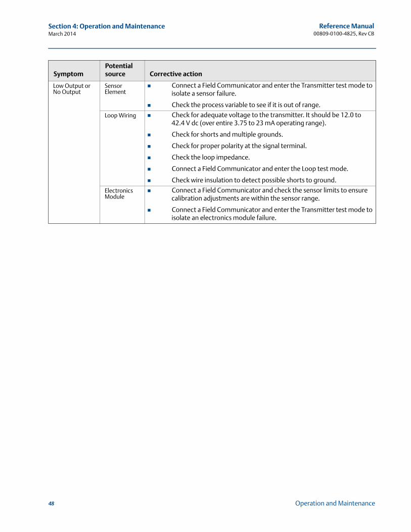
Reference Manual00809-0100-4825, Rev CB
Section 4: Operation and MaintenanceMarch 2014
Low Output or No Output
Sensor Element
Connect a Field Communicator and enter the Transmitter test mode to isolate a sensor failure.
Check the process variable to see if it is out of range.
Loop Wiring Check for adequate voltage to the transmitter. It should be 12.0 to 42.4 V dc (over entire 3.75 to 23 mA operating range).
Check for shorts and multiple grounds.
Check for proper polarity at the signal terminal.
Check the loop impedance.
Connect a Field Communicator and enter the Loop test mode.
Check wire insulation to detect possible shorts to ground.
Electronics Module
Connect a Field Communicator and check the sensor limits to ensure calibration adjustments are within the sensor range.
Connect a Field Communicator and enter the Transmitter test mode to isolate an electronics module failure.
SymptomPotential source Corrective action
48 Operation and Maintenance
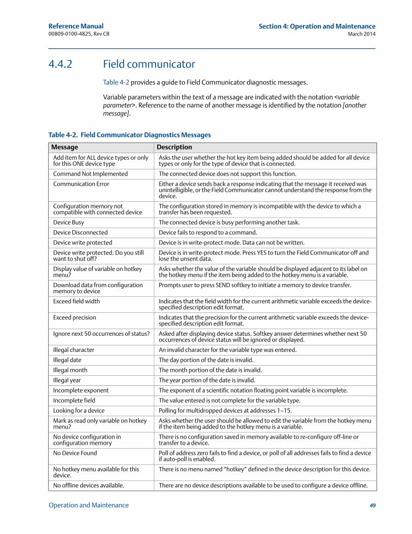
Reference Manual 00809-0100-4825, Rev CB
Section 4: Operation and MaintenanceMarch 2014
4.4.2 Field communicator
Table 4-2 provides a guide to Field Communicator diagnostic messages.
Variable parameters within the text of a message are indicated with the notation <variable parameter>. Reference to the name of another message is identified by the notation [another message].
Table 4-2. Field Communicator Diagnostics Messages
Message Description
Add item for ALL device types or only for this ONE device type
Asks the user whether the hot key item being added should be added for all device types or only for the type of device that is connected.
Command Not Implemented The connected device does not support this function.
Communication Error Either a device sends back a response indicating that the message it received was unintelligible, or the Field Communicator cannot understand the response from the device.
Configuration memory not compatible with connected device
The configuration stored in memory is incompatible with the device to which a transfer has been requested.
Device Busy The connected device is busy performing another task.
Device Disconnected Device fails to respond to a command.
Device write protected Device is in write-protect mode. Data can not be written.
Device write protected. Do you still want to shut off?
Device is in write-protect mode. Press YES to turn the Field Communicator off and lose the unsent data.
Display value of variable on hotkey menu?
Asks whether the value of the variable should be displayed adjacent to its label on the hotkey menu if the item being added to the hotkey menu is a variable.
Download data from configuration memory to device
Prompts user to press SEND softkey to initiate a memory to device transfer.
Exceed field width Indicates that the field width for the current arithmetic variable exceeds the device- specified description edit format.
Exceed precision Indicates that the precision for the current arithmetic variable exceeds the device- specified description edit format.
Ignore next 50 occurrences of status? Asked after displaying device status. Softkey answer determines whether next 50 occurrences of device status will be ignored or displayed.
Illegal character An invalid character for the variable type was entered.
Illegal date The day portion of the date is invalid.
Illegal month The month portion of the date is invalid.
Illegal year The year portion of the date is invalid.
Incomplete exponent The exponent of a scientific notation floating point variable is incomplete.
Incomplete field The value entered is not complete for the variable type.
Looking for a device Polling for multidropped devices at addresses 1–15.
Mark as read only variable on hotkey menu?
Asks whether the user should be allowed to edit the variable from the hotkey menu if the item being added to the hotkey menu is a variable.
No device configuration in configuration memory
There is no configuration saved in memory available to re-configure off-line or transfer to a device.
No Device Found Poll of address zero fails to find a device, or poll of all addresses fails to find a device if auto-poll is enabled.
No hotkey menu available for this device.
There is no menu named “hotkey” defined in the device description for this device.
No offline devices available. There are no device descriptions available to be used to configure a device offline.
49Operation and Maintenance
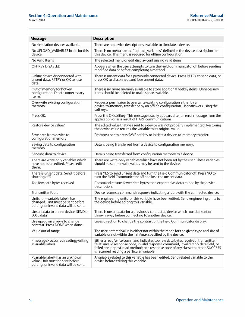
Reference Manual00809-0100-4825, Rev CB
Section 4: Operation and MaintenanceMarch 2014
No simulation devices available. There are no device descriptions available to simulate a device.
No UPLOAD_VARIABLES in ddl for this device
There is no menu named “upload_variables” defined in the device description for this device. This menu is required for offline configuration.
No Valid Items The selected menu or edit display contains no valid items.
OFF KEY DISABLED Appears when the user attempts to turn the Field Communicator off before sending modified data or before completing a method.
Online device disconnected with unsent data. RETRY or OK to lose data.
There is unsent data for a previously connected device. Press RETRY to send data, or press OK to disconnect and lose unsent data.
Out of memory for hotkey configuration. Delete unnecessary items.
There is no more memory available to store additional hotkey items. Unnecessary items should be deleted to make space available.
Overwrite existing configuration memory
Requests permission to overwrite existing configuration either by a device-to-memory transfer or by an offline configuration. User answers using the softkeys.
Press OK. Press the OK softkey. This message usually appears after an error message from the application or as a result of HART communications.
Restore device value? The edited value that was sent to a device was not properly implemented. Restoring the device value returns the variable to its original value.
Save data from device to configuration memory
Prompts user to press SAVE softkey to initiate a device-to-memory transfer.
Saving data to configuration memory.
Data is being transferred from a device to configuration memory.
Sending data to device. Data is being transferred from configuration memory to a device.
There are write only variables which have not been edited. Please edit them.
There are write-only variables which have not been set by the user. These variables should be set or invalid values may be sent to the device.
There is unsent data. Send it before shutting off?
Press YES to send unsent data and turn the Field Communicator off. Press NO to turn the Field Communicator off and lose the unsent data.
Too few data bytes received Command returns fewer data bytes than expected as determined by the device description.
Transmitter Fault Device returns a command response indicating a fault with the connected device.
Units for <variable label> has changed. Unit must be sent before editing, or invalid data will be sent.
The engineering units for this variable have been edited. Send engineering units to the device before editing this variable.
Unsent data to online device. SEND or LOSE data
There is unsent data for a previously connected device which must be sent or thrown away before connecting to another device.
Use up/down arrows to change contrast. Press DONE when done.
Gives direction to change the contrast of the Field Communicator display.
Value out of range The user-entered value is either not within the range for the given type and size of variable or not within the min/max specified by the device.
<message> occurred reading/writing <variable label>
Either a read/write command indicates too few data bytes received, transmitter fault, invalid response code, invalid response command, invalid reply data field, or failed pre- or post-read method; or a response code of any class other than SUCCESS is returned reading a particular variable.
<variable label> has an unknown value. Unit must be sent before editing, or invalid data will be sent.
A variable related to this variable has been edited. Send related variable to the device before editing this variable.
Message Description
50 Operation and Maintenance
Reference Manual 00809-0100-4825, Rev CB
Appendix A: Specifications and reference dataMarch 2014
Appendix A Specifications and reference data
Transmitter specifications . . . . . . . . . . . . . . . . . . . . . . . . . . . . . . . . . . . . . . . . . . . . . . . . . . . . . . . . . . . . page 51Sensor specifications . . . . . . . . . . . . . . . . . . . . . . . . . . . . . . . . . . . . . . . . . . . . . . . . . . . . . . . . . . . . . . . . page 57Dimensional drawings . . . . . . . . . . . . . . . . . . . . . . . . . . . . . . . . . . . . . . . . . . . . . . . . . . . . . . . . . . . . . . . page 60Ordering information . . . . . . . . . . . . . . . . . . . . . . . . . . . . . . . . . . . . . . . . . . . . . . . . . . . . . . . . . . . . . . . . page 62
A.1 Transmitter specifications
A.1.1 Functional specifications
Inputs
User-selectable. See “Transmitter accuracy and ambient temperature effects” on page 55 for sensor options.
Output
2-wire 4–20 mA, linear with temperature or input; digital output signal superimposed on 4–20 mA signal, available for a Field communicator or control system interface
Isolation
Input/output isolation tested to 500 Vac rms (707 Vdc) at 50/60 Hz
Power supply
An external power supply is required. The transmitter operates on 12.0 to 42.4 Vdc transmitter terminal voltage with load resistance between 250 and 1100 ohms. A minimum of 17.75 Vdc power supply is required with a load of 250 ohms. Transmitter power terminals are rated to 42.4 Vdc. A Field Communicator requires a loop resistance between 250 and 1100 ohms. Do not communicate with the transmitter when power is below 12 Vdc at the transmitter terminals.
Humidity limits
0–99% relative humidity, non-condensing
NAMUR recommendations
The Rosemount 248 meets the following NAMUR recommendations:
NE 21 – Electromagnetic compatibility (EMC) for Process and Laboratory Apparatus
NE 43 – Standard of the signal level breakdown information of digital transmitters
NE 89 – Standard of temperature transmitters with digital signal processing
51Specifications and Reference Data
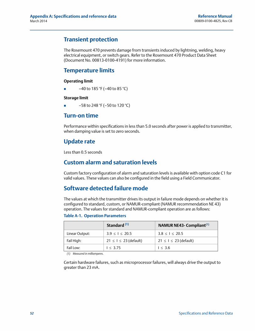
Reference Manual00809-0100-4825, Rev CB
Appendix A: Specifications and reference dataMarch 2014
Transient protection
The Rosemount 470 prevents damage from transients induced by lightning, welding, heavy electrical equipment, or switch gears. Refer to the Rosemount 470 Product Data Sheet (Document No. 00813-0100-4191) for more information.
Temperature limits
Operating limit
–40 to 185 °F (–40 to 85 °C)
Storage limit
–58 to 248 °F (–50 to 120 °C)
Turn-on time
Performance within specifications in less than 5.0 seconds after power is applied to transmitter, when damping value is set to zero seconds.
Update rate
Less than 0.5 seconds
Custom alarm and saturation levels
Custom factory configuration of alarm and saturation levels is available with option code C1 for valid values. These values can also be configured in the field using a Field Communicator.
Software detected failure mode
The values at which the transmitter drives its output in failure mode depends on whether it is configured to standard, custom, or NAMUR-compliant (NAMUR recommendation NE 43) operation. The values for standard and NAMUR-compliant operation are as follows:
Certain hardware failures, such as microprocessor failures, will always drive the output to greater than 23 mA.
Table A-1. Operation Parameters
Standard (1)
(1) Measured in milliamperes.
NAMUR NE43- Compliant(1)
Linear Output: 3.9 I 20.5 3.8 I 20.5
Fail High: 21 I 23 (default) 21 I 23 (default)
Fail Low: I 3.75 I 3.6
52 Specifications and Reference Data
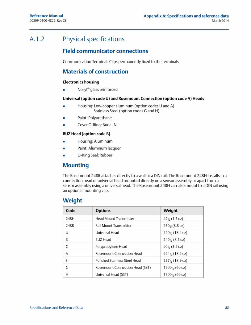
Reference Manual 00809-0100-4825, Rev CB
Appendix A: Specifications and reference dataMarch 2014
A.1.2 Physical specifications
Field communicator connections
Communication Terminal: Clips permanently fixed to the terminals
Materials of construction
Electronics housing
Noryl® glass reinforced
Universal (option code U) and Rosemount Connection (option code A) Heads
Housing: Low-copper aluminum (option codes U and A)Stainless Steel (option codes G and H)
Paint: Polyurethane
Cover O-Ring: Buna–N
BUZ Head (option code B)
Housing: Aluminum
Paint: Aluminum lacquer
O-Ring Seal: Rubber
Mounting
The Rosemount 248R attaches directly to a wall or a DIN rail. The Rosemount 248H installs in a connection head or universal head mounted directly on a sensor assembly or apart from a sensor assembly using a universal head. The Rosemount 248H can also mount to a DIN rail using an optional mounting clip.
Weight
Code Options Weight
248H Head Mount Transmitter 42 g (1.5 oz)
248R Rail Mount Transmitter 250g (8.8 oz)
U Universal Head 520 g (18.4 oz)
B BUZ Head 240 g (8.5 oz)
C Polypropylene Head 90 g (3.2 oz)
A Rosemount Connection Head 524 g (18.5 oz)
S Polished Stainless Steel Head 537 g (18.9 oz)
G Rosemount Connection Head (SST) 1700 g (60 oz)
H Universal Head (SST) 1700 g (60 oz)
53Specifications and Reference Data

Reference Manual00809-0100-4825, Rev CB
Appendix A: Specifications and reference dataMarch 2014
Enclosure ratings
The Universal (option code U) and Rosemount Connection (option code A) Heads are NEMA 4X, IP66, and IP68. The Universal Head with 1/2-in. NPT threads is CSA Enclosure Type 4X. The BUZ head (option code B) is IP54.
A.1.3 Performance specifications
EMC (ElectroMagnetic Compatibility) NAMUR NE21 Standard
The Rosemount 248 meets the requirements for NAMUR NE21 Rating.
CE mark
The Rosemount 248 meets all requirements listed under IEC 61326: Amendment 1, 1998.
Power supply effect
Less than ±0.005% of span per volt
Vibration effect
The Rosemount 248 is tested to the following specifications with no effect on performance:
Stability
For RTD and thermocouple inputs, the transmitter will have a stability of ±0.1% of reading or 0.1 °C (whichever is greater) for twelve months.
Self calibration
The analog-to-digital measurement circuitry automatically self-calibrates for each temperature update by comparing the dynamic measurement to extremely stable and accurate internal reference elements.
Susceptibility Parameter Influence
ESD 6 kV contact discharge8 kV air discharge None
Radiated 80 – 1000 MHz at 10 V/m AM None
Burst 1 kV for I.O. None
Surge 0.5 kV line–line1 kV line–ground None
Conducted 150 kHz to 80 MHz at 10 V None
Frequency Vibration
10 to 60 Hz 0.21 mm displacement
60 to 2000 Hz 3 g peak acceleration
54 Specifications and Reference Data
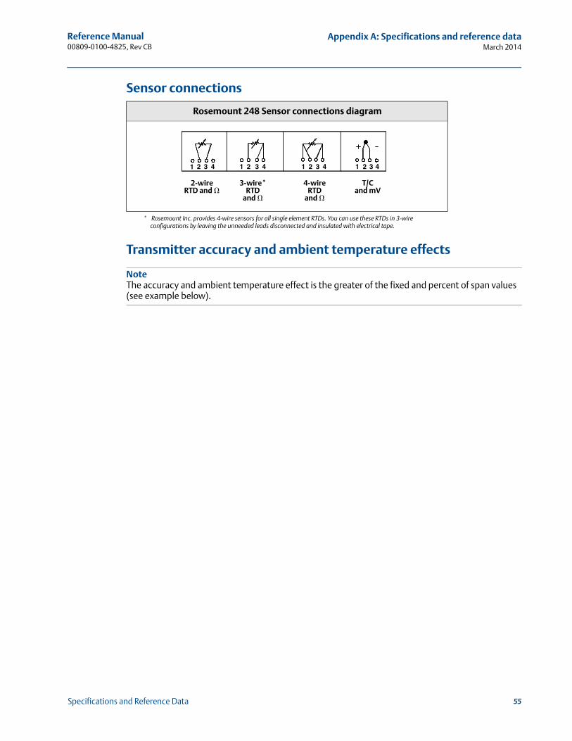
Reference Manual 00809-0100-4825, Rev CB
Appendix A: Specifications and reference dataMarch 2014
Sensor connections
Transmitter accuracy and ambient temperature effects
NoteThe accuracy and ambient temperature effect is the greater of the fixed and percent of span values (see example below).
Rosemount 248 Sensor connections diagram
* Rosemount Inc. provides 4-wire sensors for all single element RTDs. You can use these RTDs in 3-wire configurations by leaving the unneeded leads disconnected and insulated with electrical tape.
1 2 3 42 3 4 1 2 3 4 1 2 3 41
2-wire RTD and �
3-wire* RTD
and �
4-wire RTD
and �
T/C and mV
55Specifications and Reference Data
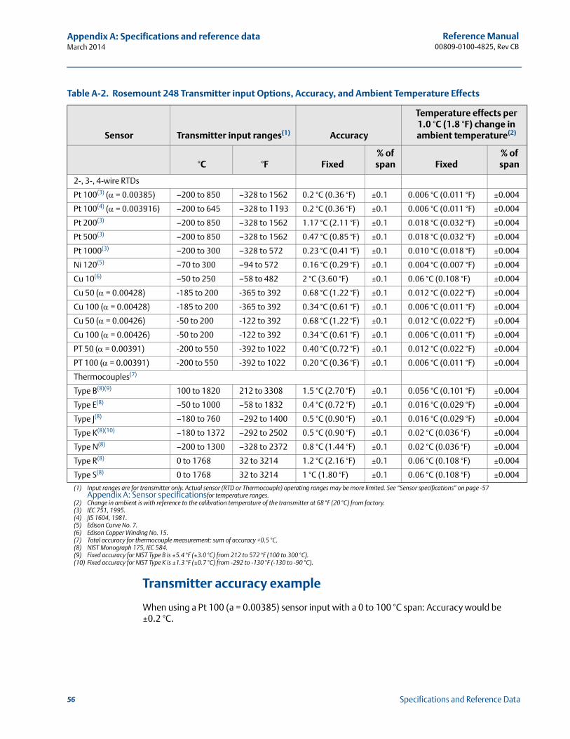
Reference Manual00809-0100-4825, Rev CB
Appendix A: Specifications and reference dataMarch 2014
Transmitter accuracy example
When using a Pt 100 (a = 0.00385) sensor input with a 0 to 100 °C span: Accuracy would be ±0.2 °C.
Table A-2. Rosemount 248 Transmitter input Options, Accuracy, and Ambient Temperature Effects
Sensor Transmitter input ranges(1)
(1) Input ranges are for transmitter only. Actual sensor (RTD or Thermocouple) operating ranges may be more limited. See “Sensor specifications” on page -57 Appendix A: Sensor specificationsfor temperature ranges.
Accuracy
Temperature effects per 1.0 °C (1.8 °F) change in ambient temperature(2)
(2) Change in ambient is with reference to the calibration temperature of the transmitter at 68 °F (20 °C) from factory.
°C °F Fixed% of span Fixed
% of span
2-, 3-, 4-wire RTDs
Pt 100(3) ( = 0.00385)
(3) IEC 751, 1995.
–200 to 850 –328 to 1562 0.2 °C (0.36 °F) ±0.1 0.006 °C (0.011 °F) ±0.004
Pt 100(4) ( = 0.003916)
(4) JIS 1604, 1981.
–200 to 645 –328 to 1193 0.2 °C (0.36 °F) ±0.1 0.006 °C (0.011 °F) ±0.004
Pt 200(3) –200 to 850 –328 to 1562 1.17 °C (2.11 °F) ±0.1 0.018 °C (0.032 °F) ±0.004
Pt 500(3) –200 to 850 –328 to 1562 0.47 °C (0.85 °F) ±0.1 0.018 °C (0.032 °F) ±0.004
Pt 1000(3) –200 to 300 –328 to 572 0.23 °C (0.41 °F) ±0.1 0.010 °C (0.018 °F) ±0.004
Ni 120(5)
(5) Edison Curve No. 7.
–70 to 300 –94 to 572 0.16 °C (0.29 °F) ±0.1 0.004 °C (0.007 °F) ±0.004
Cu 10(6)
(6) Edison Copper Winding No. 15.
–50 to 250 –58 to 482 2 °C (3.60 °F) ±0.1 0.06 °C (0.108 °F) ±0.004
Cu 50 ( = 0.00428) -185 to 200 -365 to 392 0.68 °C (1.22 °F) ±0.1 0.012 °C (0.022 °F) ±0.004
Cu 100 ( = 0.00428) -185 to 200 -365 to 392 0.34 °C (0.61 °F) ±0.1 0.006 °C (0.011 °F) ±0.004
Cu 50 ( = 0.00426) -50 to 200 -122 to 392 0.68 °C (1.22 °F) ±0.1 0.012 °C (0.022 °F) ±0.004
Cu 100 ( = 0.00426) -50 to 200 -122 to 392 0.34 °C (0.61 °F) ±0.1 0.006 °C (0.011 °F) ±0.004
PT 50 ( = 0.00391) -200 to 550 -392 to 1022 0.40 °C (0.72 °F) ±0.1 0.012 °C (0.022 °F) ±0.004
PT 100 ( = 0.00391) -200 to 550 -392 to 1022 0.20 °C (0.36 °F) ±0.1 0.006 °C (0.011 °F) ±0.004
Thermocouples(7)
(7) Total accuracy for thermocouple measurement: sum of accuracy +0.5 °C.
Type B(8)(9)
(8) NIST Monograph 175, IEC 584.(9) Fixed accuracy for NIST Type B is ±5.4 °F (±3.0 °C) from 212 to 572 °F (100 to 300 °C).
100 to 1820 212 to 3308 1.5 °C (2.70 °F) ±0.1 0.056 °C (0.101 °F) ±0.004
Type E(8) –50 to 1000 –58 to 1832 0.4 °C (0.72 °F) ±0.1 0.016 °C (0.029 °F) ±0.004
Type J(8) –180 to 760 –292 to 1400 0.5 °C (0.90 °F) ±0.1 0.016 °C (0.029 °F) ±0.004
Type K(8)(10)
(10) Fixed accuracy for NIST Type K is ±1.3 °F (±0.7 °C) from -292 to -130 °F (-130 to -90 °C).
–180 to 1372 –292 to 2502 0.5 °C (0.90 °F) ±0.1 0.02 °C (0.036 °F) ±0.004
Type N(8) –200 to 1300 –328 to 2372 0.8 °C (1.44 °F) ±0.1 0.02 °C (0.036 °F) ±0.004
Type R(8) 0 to 1768 32 to 3214 1.2 °C (2.16 °F) ±0.1 0.06 °C (0.108 °F) ±0.004
Type S(8) 0 to 1768 32 to 3214 1 °C (1.80 °F) ±0.1 0.06 °C (0.108 °F) ±0.004
56 Specifications and Reference Data
Reference Manual 00809-0100-4825, Rev CB
Appendix A: Specifications and reference dataMarch 2014
Transmitter temperature effects example
Transmitters can be installed in locations where the ambient temperature is between –40 and 85 °C (–40 and 185 °F). In order to maintain excellent accuracy performance, each transmitter is individually characterized over this ambient temperature range at the factory.
When using a Pt 100 ( = 0.00385) sensor input with a 0-100 °C span at 30 °C ambient tempera-ture-Temperature Effects: 0.006 °C x (30 - 20) = 0.06 °C
Total transmitter error
Worst Case Transmitter Error: Accuracy + Temperature Effects = 0.2 °C + 0.06 °C = 0.26 °C
Total Probable Transmitter Error:
A.2 Sensor specifications
A.2.1 Thermocouples – IEC 584
Applicable to sensors offered in Table A-3 on page A-57
Construction
Rosemount DIN plate and 1/2-in. adapter style thermocouples are manufactured from selected materials to meet IEC 584 Tolerance Class 1. The junction of these wires is laser-welded to form a pure joint, maintaining circuit integrity and ensuring highest accuracy.
Lead wires
Internal – 18 SWG (16 AWG) solid wire (max), 19 SWG (18 AWG) solid wire (min.). External extension leads, type J and K – 0.8 mm minimum stranded wire, PTFE insulation. Color coded per IEC 584
Insulation resistance
1000 megaohms minimum insulation resistance when measured at 500 Vdc at room temperature.
Table A-3. Characteristics of DIN Plate and 1/2-in. NPT Adapter Style Thermocouples
Characteristics Type J Type K
Alloys (wire color) Fe (+ black), CuNi (- white) NiCr (+ green), NiAl (- white)
Sheath Material 1.4541 (AISI 321) Inconel 600
Temp Range (°C) – 40 to 750 – 40 to 1000
Tolerance, DIN EN 60584-2 ±1.5 °C or ±0.4% of measured temp, whichever is greater
0.22 0.062+ 0.21=
57Specifications and Reference Data

Reference Manual00809-0100-4825, Rev CB
Appendix A: Specifications and reference dataMarch 2014
A.2.2 Thermocouples – ASTM E- 230
Applicable to sensors offered in Table A-4 on page A-58
Construction
Rosemount 1/2-in. adapter style thermocouples are manufactured using ISA Type J or K wire with special limits of error accuracy. The junction of these wires is fusion-welded to form a pure joint, to maintain the integrity of the circuit and to ensure the highest accuracy.
Lead wires
Thermocouple, internal – 16 AWG solid wire (max), 18 AWG solid wire (min.). External lead wire – 20 AWG wire, PTFE insulation. Color coded per ASTM E-230
Insulation resistance
100 megaohms minimum insulation resistance when measured at 100 Vdc at room temperature
A.2.3 RTDs
Sensor type
100 ohm RTD at 0 °C, = 0.00385 ohms/ohm/°C.
Accuracy
Meets IEC 751 Class B tolerances
Temperature range
–50 to 450 °C (–58 to 842 °F)
Self heating
0.15 °K/mW when measured per method defined in DIN EN 60751:1996 or 16 mW minimum power dissipation required to cause a 1 °C (1.8 °F) temperature measurement error in water flowing at 0.91 m/s (3 ft/s)
Table A-4. Characteristics of DIN Plate and 1/2-in. NPT Adapter Style Thermocouples
Characteristics Type J Type K
Alloys (wire color) Iron/Constantan (white/red) Chromel/Alumel (yellow/red)
Temp Range 0 to 760 °C (32 to 1400 °F) 0 to 1150°C (32 to 2102 °F)
Tolerance ±1.1 °C or ±0.4% of measured temp, whichever is greater
± 1.1 °C or ±0.4% of measured temp, whichever is greater
Sheath Material 304 SST Inconel
58 Specifications and Reference Data
Reference Manual 00809-0100-4825, Rev CB
Appendix A: Specifications and reference dataMarch 2014
Thermal response time
9 seconds maximum required to reach 50% sensor response when tested in flowing water according to IEC 751 or 12 seconds maximum required to reach 63.2% sensor response in water flowing at 0.91 m/s (3 ft/s).
Immersion error
60 mm minimum usable depth of immersion when tested according to IEC 751.
Insulation resistance
500 megaohms minimum insulation resistance when measured at 500 V dc at room temperature.
Sheath material
321 SST with mineral-insulated cable construction.
Lead wires
PTFE insulated, coated 22 gauge stranded copper wire.
A.2.4 Thermowells
Materials
Barstock Thermowells: 316L SST (1.4404)
Tubular Thermowells: 1.4571 (316 Ti)
Construction
Thermowell bodies are either machined from solid barstock or manufactured using swaged tubes. Flange mounts are seal welded to the thermowell body with the exception of Class 900 flanges and above, which are full penetration welded. Surface finish of machined stems is 0.8 m (32 in. CLA.N6).
Material certification (option code Q8) and pressure testing (option code R01) are available. Flanged thermowells generally conform to the specifications of ASME B 16.5 (ANSI), DIN 2519, 2527, 2633, 2635, and DIN 2526 Type C
Other thermowell materials and styles are available in Volume 1, 2, and 3 of the Temperature Sensor and Accessories Product Data Sheet.
59Specifications and Reference Data
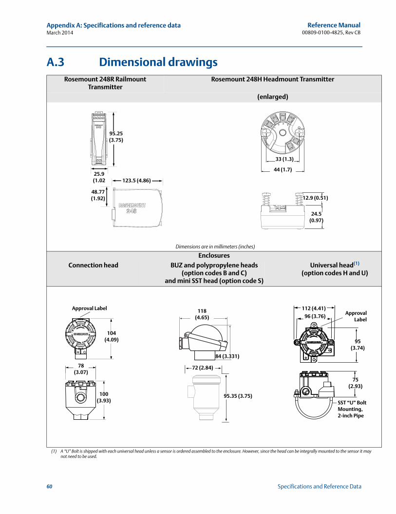
Reference Manual00809-0100-4825, Rev CB
Appendix A: Specifications and reference dataMarch 2014
y
A.3 Dimensional drawingsRosemount 248R Railmount
TransmitterRosemount 248H Headmount Transmitter
(enlarged)
Dimensions are in millimeters (inches)
Enclosures
Connection head BUZ and polypropylene heads (option codes B and C)
and mini SST head (option code S)
Universal head(1) (option codes H and U)
(1) A “U” Bolt is shipped with each universal head unless a sensor is ordered assembled to the enclosure. However, since the head can be integrally mounted to the sensor it manot need to be used.
123.5 (4.86)
95.25 (3.75)
25.9 (1.02
48.77 (1.92)
44 (1.7)
33 (1.3)
12.9 (0.51)
24.5 (0.97)
104 (4.09)
100 (3.93)
78 (3.07)
Approval Label
84 (3.331)
118 (4.65)
95.35 (3.75)
72 (2.84)
95 (3.74)
96 (3.76)
112 (4.41)
SST “U” Bolt Mounting, 2-inch Pipe
ApprovalLabel
75 (2.93)
60 Specifications and Reference Data
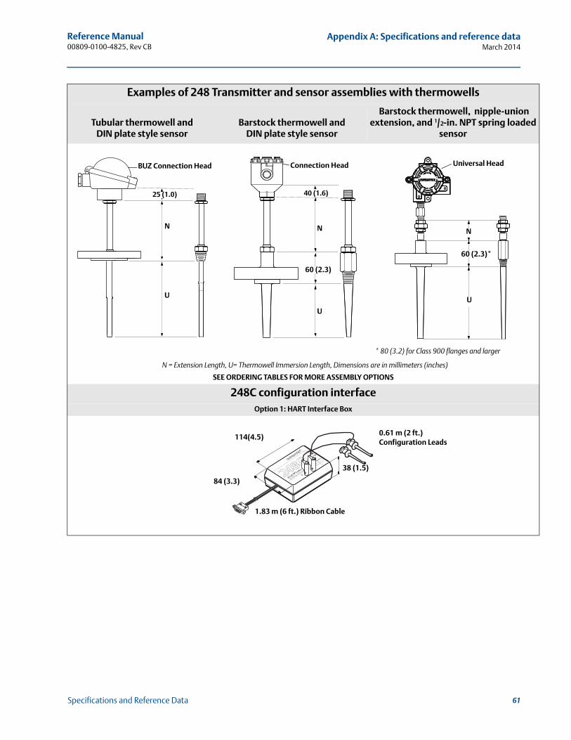
Reference Manual 00809-0100-4825, Rev CB
Appendix A: Specifications and reference dataMarch 2014
d
Examples of 248 Transmitter and sensor assemblies with thermowells
Tubular thermowell and DIN plate style sensor
Barstock thermowell and DIN plate style sensor
Barstock thermowell, nipple-union extension, and 1/2-in. NPT spring loade
sensor
* 80 (3.2) for Class 900 flanges and larger
N = Extension Length, U= Thermowell Immersion Length, Dimensions are in millimeters (inches)
SEE ORDERING TABLES FOR MORE ASSEMBLY OPTIONS
248C configuration interfaceOption 1: HART Interface Box
N
U
25 (1.0)
BUZ Connection Head
N
U
40 (1.6)
60 (2.3)
Connection Head
U
N
60 (2.3)*
Universal Head
On
Off
+See warnings on back la
bel
0.61 m (2 ft.) Configuration Leads
38 (1.5)
1.83 m (6 ft.) Ribbon Cable
84 (3.3)
114(4.5)
61Specifications and Reference Data
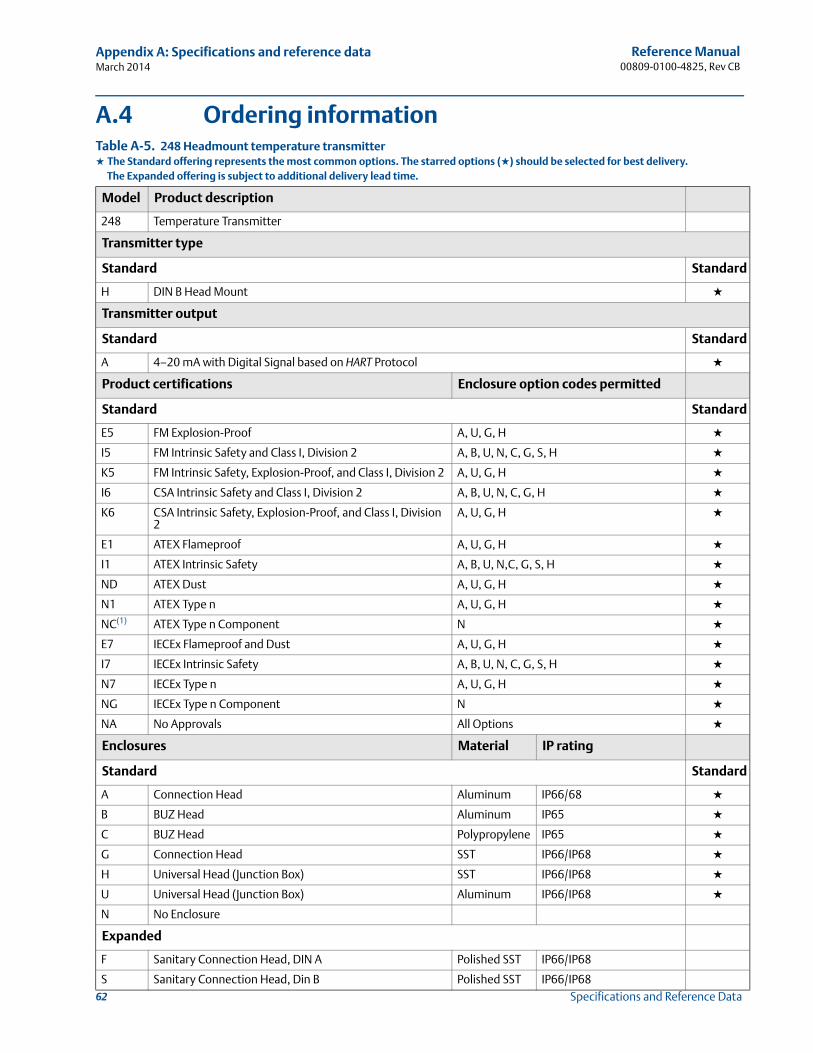
Reference Manual00809-0100-4825, Rev CB
Appendix A: Specifications and reference dataMarch 2014
62 Specifications and Reference Data
A.4 Ordering informationTable A-5. 248 Headmount temperature transmitter★ The Standard offering represents the most common options. The starred options (★) should be selected for best delivery.__The Expanded offering is subject to additional delivery lead time.
Model Product description
248 Temperature Transmitter
Transmitter type
Standard Standard
H DIN B Head Mount ★
Transmitter output
Standard Standard
A 4–20 mA with Digital Signal based on HART Protocol ★
Product certifications Enclosure option codes permitted
Standard Standard
E5 FM Explosion-Proof A, U, G, H ★
I5 FM Intrinsic Safety and Class I, Division 2 A, B, U, N, C, G, S, H ★
K5 FM Intrinsic Safety, Explosion-Proof, and Class I, Division 2 A, U, G, H ★
I6 CSA Intrinsic Safety and Class I, Division 2 A, B, U, N, C, G, H ★
K6 CSA Intrinsic Safety, Explosion-Proof, and Class I, Division 2
A, U, G, H ★
E1 ATEX Flameproof A, U, G, H ★
I1 ATEX Intrinsic Safety A, B, U, N,C, G, S, H ★
ND ATEX Dust A, U, G, H ★
N1 ATEX Type n A, U, G, H ★
NC(1) ATEX Type n Component N ★
E7 IECEx Flameproof and Dust A, U, G, H ★
I7 IECEx Intrinsic Safety A, B, U, N, C, G, S, H ★
N7 IECEx Type n A, U, G, H ★
NG IECEx Type n Component N ★
NA No Approvals All Options ★
Enclosures Material IP rating
Standard Standard
A Connection Head Aluminum IP66/68 ★
B BUZ Head Aluminum IP65 ★
C BUZ Head Polypropylene IP65 ★
G Connection Head SST IP66/IP68 ★
H Universal Head (Junction Box) SST IP66/IP68 ★
U Universal Head (Junction Box) Aluminum IP66/IP68 ★
N No Enclosure
Expanded
F Sanitary Connection Head, DIN A Polished SST IP66/IP68
S Sanitary Connection Head, Din B Polished SST IP66/IP68
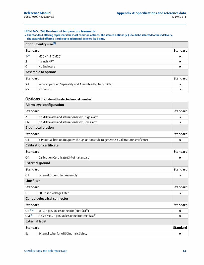
Reference Manual 00809-0100-4825, Rev CB
Appendix A: Specifications and reference dataMarch 2014
Conduit entry size(2)
Standard Standard
1(3) M20 x 1.5 (CM20) ★
2 1/2-inch NPT ★
0 No Enclosure ★
Assemble to options
Standard Standard
XA Sensor Specified Separately and Assembled to Transmitter ★
NS No Sensor ★
Options (Include with selected model number)
Alarm level configuration
Standard Standard
A1 NAMUR alarm and saturation levels, high alarm ★
CN NAMUR alarm and saturation levels, low alarm ★
5-point calibration
Standard Standard
C4 5-Point Calibration (Requires the Q4 option code to generate a Calibration Certificate) ★
Calibration certificate
Standard Standard
Q4 Calibration Certificate (3-Point standard) ★
External ground
Standard Standard
G1 External Ground Lug Assembly ★
Line filter
Standard Standard
F6 60 Hz line Voltage Filter ★
Conduit electrical connector
Standard Standard
GE(4)(2) M12, 4 pin, Male Connector (eurofast®) ★
GM(2) A-size Mini, 4 pin, Male Connector (minifast®) ★
External label
Standard Standard
EL External Label for ATEX Intrinsic Safety ★
Table A-5. 248 Headmount temperature transmitter★ The Standard offering represents the most common options. The starred options (★) should be selected for best delivery.__The Expanded offering is subject to additional delivery lead time.
63Specifications and Reference Data
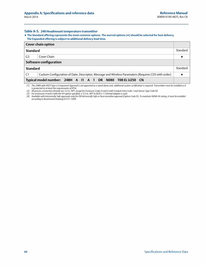
Reference Manual00809-0100-4825, Rev CB
Appendix A: Specifications and reference dataMarch 2014
Cover chain option
Standard Standard
G3 Cover Chain ★
Software configuration
Standard Standard
C1 Custom Configuration of Date, Descriptor, Message and Wireless Paramaters (Requires CDS with order) ★
Typical model number: 248H A I1 A 1 DR N080 T08 EL U250 CN
(1) The 248H with ATEX Type n Component Approval is not approved as a stand alone unit, additional system certification is required. Transmitter must be installed so it is protected to at least the requirements of IP54.
(2) All process connection threads are 1/2 in. NPT, except for Enclosure Codes H and U with Conduit Entry Code 1 and Sensor Type Code NS(3) For enclosures H and U with the XA option specified, a 1/2-in. NPT to M20 x 1.5 thread adapter is used.(4) Available with Intrinsically Safe approvals only for FM Intrinsically Safe or Non-Incendive approval (Option Code I5). To maintain NEMA 4X rating, it must be installed
according to Rosemount Drawing 03151-1009.
Table A-5. 248 Headmount temperature transmitter★ The Standard offering represents the most common options. The starred options (★) should be selected for best delivery.__The Expanded offering is subject to additional delivery lead time.
64 Specifications and Reference Data

Reference Manual 00809-0100-4825, Rev CB
Appendix B: Product CertificationsMarch 2014
Appendix B Product Certifications
Approved Manufacturing Locations . . . . . . . . . . . . . . . . . . . . . . . . . . . . . . . . . . . . . . . . . . . page 65European Directive Information . . . . . . . . . . . . . . . . . . . . . . . . . . . . . . . . . . . . . . . . . . . . . . . page 65Ordinary Location Certification from FM Approvals . . . . . . . . . . . . . . . . . . . . . . . . . . . . . . page 65Installation drawings . . . . . . . . . . . . . . . . . . . . . . . . . . . . . . . . . . . . . . . . . . . . . . . . . . . . . . . . page 72
B.1 Approved Manufacturing Locations
Rosemount Inc. – Chanhassen, Minnesota, USA
Rosemount Temperature GmbH – Germany
Emerson Process Management Asia Pacific – Singapore
B.2 European Directive Information
A copy of the EC Declaration of Conformity can be found at the end of the Quick Start Guide. The most recent revision of the EC Declaration of Conformity can be found at www.rosemount.com.
B.3 Ordinary Location Certification from FM Approvals
As standard, the transmitter has been examined and tested to determine that the design meets the basic electrical, mechanical, and fire protection requirements by FM Approvals, a nationally recognized test laboratory (NRTL) as accredited by the Federal Occupational Safety and Health Administration (OSHA).
B.3.1 North America
E5 FM Explosionproof, Dust-Ignitionproof, and NonincendiveCertificate: 3016555Standards Used: FM Class 3600:1998, FM Class 3611:2004, FM Class 3615:1989, FM Class 3810:2005, ANSI/ISA 60079-0:2009, ANSI/ISA 60079-11:2009, IEC 60529: 2001, NEMA - 250: 1991Markings: XP CL I, DIV 1, GP B, C, D; DIP CL II/III, DIV 1, GP E, F, G when installed per Rosemount drawing 00248-1065. T5(-40 °C Ta+85 °C); NI CL1, DIV 2, GP A, B, C, D T6(-40 °C Ta +40 °C), T5(-40 °C Ta +75 °C) when installed per Rosemount drawing 00248-1055; Type 4X; IP66/68
65Product Certifications
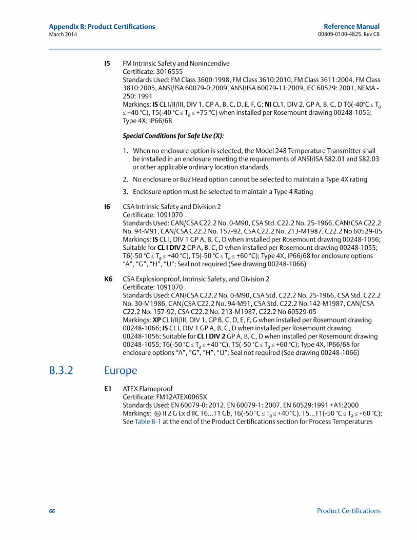
Reference Manual00809-0100-4825, Rev CB
Appendix B: Product CertificationsMarch 2014
I5 FM Intrinsic Safety and NonincendiveCertificate: 3016555Standards Used: FM Class 3600:1998, FM Class 3610:2010, FM Class 3611:2004, FM Class 3810:2005, ANSI/ISA 60079-0:2009, ANSI/ISA 60079-11:2009, IEC 60529: 2001, NEMA - 250: 1991Markings: IS CL I/II/III, DIV 1, GP A, B, C, D, E, F, G; NI CL1, DIV 2, GP A, B, C, D T6(-40°C Ta +40 °C), T5(-40 °C Ta +75 °C) when installed per Rosemount drawing 00248-1055; Type 4X; IP66/68
Special Conditions for Safe Use (X):
1. When no enclosure option is selected, the Model 248 Temperature Transmitter shall be installed in an enclosure meeting the requirements of ANSI/ISA S82.01 and S82.03 or other applicable ordinary location standards
2. No enclosure or Buz Head option cannot be selected to maintain a Type 4X rating
3. Enclosure option must be selected to maintain a Type 4 Rating
I6 CSA Intrinsic Safety and Division 2Certificate: 1091070Standards Used: CAN/CSA C22.2 No. 0-M90, CSA Std. C22.2 No. 25-1966, CAN/CSA C22.2 No. 94-M91, CAN/CSA C22.2 No. 157-92, CSA C22.2 No. 213-M1987, C22.2 No 60529-05Markings: IS CL I, DIV 1 GP A, B, C, D when installed per Rosemount drawing 00248-1056; Suitable for CL I DIV 2 GP A, B, C, D when installed per Rosemount drawing 00248-1055; T6(-50 °C Ta +40 °C), T5(-50 °C Ta +60 °C); Type 4X, IP66/68 for enclosure options “A”, “G”, “H”, “U”; Seal not required (See drawing 00248-1066)
K6 CSA Explosionproof, Intrinsic Safety, and Division 2Certificate: 1091070Standards Used: CAN/CSA C22.2 No. 0-M90, CSA Std. C22.2 No. 25-1966, CSA Std. C22.2 No. 30-M1986, CAN/CSA C22.2 No. 94-M91, CSA Std. C22.2 No.142-M1987, CAN/CSA C22.2 No. 157-92, CSA C22.2 No. 213-M1987, C22.2 No 60529-05Markings: XP CL I/II/III, DIV 1, GP B, C, D, E, F, G when installed per Rosemount drawing 00248-1066; IS CL I, DIV 1 GP A, B, C, D when installed per Rosemount drawing 00248-1056; Suitable for CL I DIV 2 GP A, B, C, D when installed per Rosemount drawing 00248-1055; T6(-50 °CTa +40 °C), T5(-50 °C Ta +60 °C); Type 4X, IP66/68 for enclosure options “A”, “G”, “H”, “U”; Seal not required (See drawing 00248-1066)
B.3.2 Europe
E1 ATEX FlameproofCertificate: FM12ATEX0065X Standards Used: EN 60079-0: 2012, EN 60079-1: 2007, EN 60529:1991 +A1:2000Markings: II 2 G Ex d IIC T6…T1 Gb, T6(-50 °C Ta +40 °C), T5…T1(-50 °C Ta +60 °C);See Table B-1 at the end of the Product Certifications section for Process Temperatures
66 Product Certifications
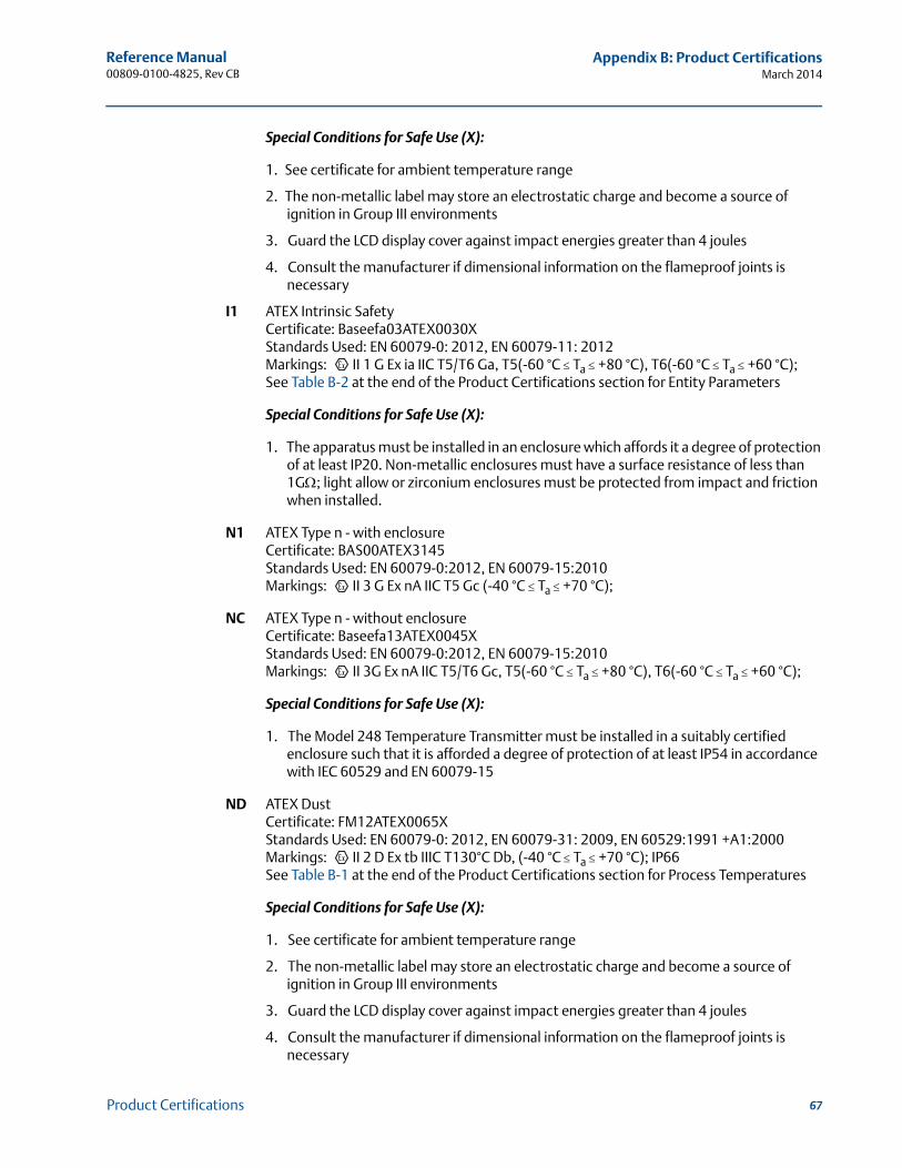
Reference Manual 00809-0100-4825, Rev CB
Appendix B: Product CertificationsMarch 2014
Special Conditions for Safe Use (X):
1. See certificate for ambient temperature range
2. The non-metallic label may store an electrostatic charge and become a source of ignition in Group III environments
3. Guard the LCD display cover against impact energies greater than 4 joules
4. Consult the manufacturer if dimensional information on the flameproof joints is necessary
I1 ATEX Intrinsic SafetyCertificate: Baseefa03ATEX0030XStandards Used: EN 60079-0: 2012, EN 60079-11: 2012Markings: II 1 G Ex ia IIC T5/T6 Ga, T5(-60 °C Ta +80 °C), T6(-60 °C Ta +60 °C);See Table B-2 at the end of the Product Certifications section for Entity Parameters
Special Conditions for Safe Use (X):
1. The apparatus must be installed in an enclosure which affords it a degree of protection of at least IP20. Non-metallic enclosures must have a surface resistance of less than 1G; light allow or zirconium enclosures must be protected from impact and friction when installed.
N1 ATEX Type n - with enclosureCertificate: BAS00ATEX3145Standards Used: EN 60079-0:2012, EN 60079-15:2010Markings: II 3 G Ex nA IIC T5 Gc (-40 °C Ta +70 °C);
NC ATEX Type n - without enclosureCertificate: Baseefa13ATEX0045XStandards Used: EN 60079-0:2012, EN 60079-15:2010Markings: II 3G Ex nA IIC T5/T6 Gc, T5(-60 °C Ta +80 °C), T6(-60 °C Ta +60 °C);
Special Conditions for Safe Use (X):
1. The Model 248 Temperature Transmitter must be installed in a suitably certified enclosure such that it is afforded a degree of protection of at least IP54 in accordance with IEC 60529 and EN 60079-15
ND ATEX DustCertificate: FM12ATEX0065X Standards Used: EN 60079-0: 2012, EN 60079-31: 2009, EN 60529:1991 +A1:2000Markings: II 2 D Ex tb IIIC T130°C Db, (-40 °C Ta +70 °C); IP66See Table B-1 at the end of the Product Certifications section for Process Temperatures
Special Conditions for Safe Use (X):
1. See certificate for ambient temperature range
2. The non-metallic label may store an electrostatic charge and become a source of ignition in Group III environments
3. Guard the LCD display cover against impact energies greater than 4 joules
4. Consult the manufacturer if dimensional information on the flameproof joints is necessary
67Product Certifications
Reference Manual00809-0100-4825, Rev CB
Appendix B: Product CertificationsMarch 2014
B.3.3 International
E7 IECEx Flameproof and DustCertificate: IECEx FMG 12.0022XStandards Used: IEC 60079-0:2011, IEC 60079-1:2007-04, IEC 60079-31:2008Markings: Ex d IIC T6…T1 Gb, T6(-50 °C Ta +40 °C), T5…T1(-50 °C Ta +60 °C); Ex tb IIIC T130°C Db, (-40 °C Ta +70 °C); IP66;See Table B-1 at the end of the Product Certifications section for Process Temperatures
Special Conditions for Safe Use (X):
1. See certificate for ambient temperature range
2. The non-metallic label may store an electrostatic charge and become a source of ignition in Group III environments
3. Guard the LCD display cover against impact energies greater than 4 joules
4. Consult the manufacturer if dimensional information on the flameproof joints is necessary
I7 IECEx Intrinsic SafetyCertificate: IECEx BAS 07.0086XStandards Used: IEC 60079-0:2011, IEC 60079-11:2011Markings: Ex ia IIC T5/T6 Ga, T5(-60 °C Ta +80 °C), T6(-60 °C Ta +60 °C);SeeTable B-2 at the end of the Product Certifications section for Entity Parameters
Special Conditions for Safe Use (X):
1. The apparatus must be installed in an enclosure which affords it a degree of protection of at least IP20. Non-metallic enclosures must have a surface resistance of less than 1G; light allow or zirconium enclosures must be protected from impact and friction when installed.
N7 IECEx Type n - with enclosureCertificate: IECEx BAS 07.0055Standards Used: IEC 60079-0:2011, IEC 60079-15:2010Markings: Ex nA IIC T5 Gc; T5(-40 °C Ta +70 °C)
NG IECEx Type n - without enclosureCertificate: IECEx BAS 13.0029XStandards Used: IEC 60079-0:2011, IEC 60079-15:2010Markings: Ex nA IIC T5/T6 Gc; T5(-60 °C Ta +80 °C), T6(-60 °C Ta +60 °C)
Special Conditions for Safe Use (X):
1. The Model 248 Temperature Transmitter must be installed in a suitably certified enclosure such that it is afforded a degree of protection of at least IP54 in accordance with IEC 60529 and IEC 60079-15.
68 Product Certifications
Reference Manual 00809-0100-4825, Rev CB
Appendix B: Product CertificationsMarch 2014
B.3.4 China
E3 China FlameproofCertificate: GYJ11.1534 Standards Used: GB3836.1-2010, GB3836.2-2010Markings: Ex d IIC T6 Gb (-40 °C Ta +65 °C)
Special Conditions for Safe Use (X):
1. Ambient temperature range is: -40 °C Ta +65 °C
2. The earth connection facility in the enclosure should be connected reliably.
3. During installation, there should be no mixture harmful to flameproof housing.
4. During installation in hazardous location, cable glands, conduits and blanking plugs, certified by state-appointed inspection bodies with Ex d IIC Gb degree, should be used.
5. During installation, use and maintenance in explosive gas atmospheres, observe the warning “Do not open when energized”.
6. End user is not permitted to change any components inside, but to settle the problem in conjunction with manufacturer to avoid damage to the product.
7. When installation, use and maintenance of this product, observe the following standards:
GB3836.13-1997 “Electrical apparatus for explosive gas atmospheres Part 13: Repair and overhaul for apparatus used in explosive gas atmospheres”
GB3836.15-2000 “Electrical apparatus for explosive gas atmospheres Part 15: Electrical installations in hazardous area (other than mines)”
GB3836.16-2006 “Electrical apparatus for explosive gas atmospheres Part 16: Inspection and maintenance of electrical installation (other than mines)”
GB50257-1996 “Code for construction and acceptance of electric device for explosion atmostpheres and fire hazard electrical equipment installation engineering”
I3 China Intrinsic SafetyCertificate: GYJ11.1535XStandards Used: GB3836.1-2010, GB3836.4-2010Markings: Ex ia IIC T5/T6; T5(-60 °C Ta +80 °C), T6(-60 °C Ta +60 °C)See Table B-2 at the end of the Product Certifications section for Entity Parameters
Special Conditions for Safe Use (X):
1. Symbol “X” is used to denote specific conditions of use:
a. The enclosure may contain light metal, attention should be taken to avoid ignition hazard due to impact or friction
b. The apparatus must be installed in an enclosure which affords it a degree of protection of at least IP20. Non-metallic enclosures must have a surface resistance of less than 1G.
69Product Certifications
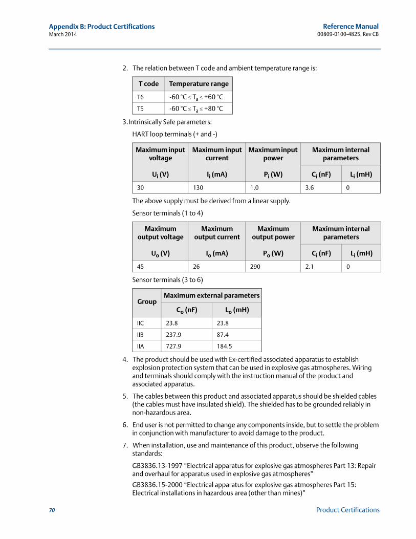
Reference Manual00809-0100-4825, Rev CB
Appendix B: Product CertificationsMarch 2014
70 Product Certifications
2. The relation between T code and ambient temperature range is:
3.Intrinsically Safe parameters:
HART loop terminals (+ and -)
The above supply must be derived from a linear supply.
Sensor terminals (1 to 4)
Sensor terminals (3 to 6)
4. The product should be used with Ex-certified associated apparatus to establish explosion protection system that can be used in explosive gas atmospheres. Wiring and terminals should comply with the instruction manual of the product and associated apparatus.
5. The cables between this product and associated apparatus should be shielded cables (the cables must have insulated shield). The shielded has to be grounded reliably in non-hazardous area.
6. End user is not permitted to change any components inside, but to settle the problem in conjunction with manufacturer to avoid damage to the product.
7. When installation, use and maintenance of this product, observe the following standards:
GB3836.13-1997 “Electrical apparatus for explosive gas atmospheres Part 13: Repair and overhaul for apparatus used in explosive gas atmospheres”
GB3836.15-2000 “Electrical apparatus for explosive gas atmospheres Part 15: Electrical installations in hazardous area (other than mines)”
T code Temperature range
T6 -60 °C Ta +60 °C
T5 -60 °C Ta +80 °C
Maximum input voltage
Ui (V)
Maximum input current
Ii (mA)
Maximum input power
Pi (W)
Maximum internal parameters
Ci (nF) Li (mH)
30 130 1.0 3.6 0
Maximum output voltage
Uo (V)
Maximum output current
Io (mA)
Maximum output power
Po (W)
Maximum internal parameters
Ci (nF) Li (mH)
45 26 290 2.1 0
GroupMaximum external parameters
Co (nF) Lo (mH)
IIC 23.8 23.8
IIB 237.9 87.4
IIA 727.9 184.5
Reference Manual 00809-0100-4825, Rev CB
Appendix B: Product CertificationsMarch 2014
GB3836.16-2006 “Electrical apparatus for explosive gas atmospheres Part 16: Inspection and maintenance of electrical installation (other than mines)”
GB50257-1996 “Code for construction and acceptance of electrical device for explosion atmospheres and fire hazard electrical equipment installation engineering”
N3 China Type nCertificate: GYJ101095Standards Used: GB3836.1-2000, GB3836.8-2003Markings: Ex nA nL IIC T5(-40 °C Ta +70 °C)
Special Conditions for Safe Use (X):
1. 248 type Temperature Assembly using temperature sensor type 65, 68, 183, 185 are certified.
2. The ambient temperature range is: (-40 °C Ta +70 °C)
3. Maximum input voltage: 42.4 V.
4. Cable glands, conduit or blanking plugs, certified by NEPSI with Exe or Ex n protection type and ½-14NPT or M20x1.5 thread type, should be used on external connections and redundant cable entries.
5. Maintenance should be done in non-hazardous location.
6. End user is not permitted to change any components inside, but to settle the problem in conjunction with manufacturer to avoid damage to the product.
7. When installation, use and maintenance of this product, observe the following standards:
GB3836.13-1997 “Electrical apparatus for explosive gas atmospheres Part 13: Repair and overhaul for apparatus used in explosive gas atmospheres”
GB3836.15-2000 “Electrical apparatus for explosive gas atmospheres Part 15: Electrical installations in hazardous area (other than mines)”
GB3836.16-2006 “Electrical apparatus for explosive gas atmospheres Part 16: Inspection and maintenance of electrical installation (other than mines)”
GB50257-1996 “Code for construction and acceptance of electrical device for explosion atmospheres and fire hazard electrical equipment installation engineering”
B.3.5 Combinations
K5 combination of E5 and I5
71Product Certifications
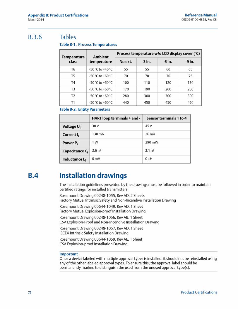
Reference Manual00809-0100-4825, Rev CB
Appendix B: Product CertificationsMarch 2014
B.3.6 Tables
B.4 Installation drawingsThe installation guidelines presented by the drawings must be followed in order to maintain certified ratings for installed transmitters.
Rosemount Drawing 00248-1055, Rev AD, 2 SheetsFactory Mutual Intrinsic Safety and Non-Incendive Installation Drawing
Rosemount Drawing 00644-1049, Rev AD, 1 SheetFactory Mutual Explosion-proof Installation Drawing
Rosemount Drawing 00248-1056, Rev AB, 1 SheetCSA Explosion-Proof and Non-Incendive Installation Drawing
Rosemount Drawing 00248-1057, Rev AD, 1 SheetIECEX Intrinsic Safety Installation Drawing
Rosemount Drawing 00644-1059, Rev AE, 1 SheetCSA Explosion-proof Installation Drawing
ImportantOnce a device labeled with multiple approval types is installed, it should not be reinstalled using any of the other labeled approval types. To ensure this, the approval label should be permanently marked to distinguish the used from the unused approval type(s).
Table B-1. Process Temperatures
Temperature class
Ambienttemperature
Process temperature w/o LCD display cover (°C)
No ext. 3 in. 6 in. 9 in.
T6 -50 °C to +40 °C 55 55 60 65
T5 -50 °C to +60 °C 70 70 70 75
T4 -50 °C to +60 °C 100 110 120 130
T3 -50 °C to +60 °C 170 190 200 200
T2 -50 °C to +60 °C 280 300 300 300
T1 -50 °C to +60 °C 440 450 450 450
Table B-2. Entity Parameters
HART loop terminals + and - Sensor terminals 1 to 4
Voltage Ui 30 V 45 V
Current Ii 130 mA 26 mA
Power Pi 1 W 290 mW
Capacitance Ci 3.6 nF 2.1 nF
Inductance Li 0 mH 0 H
72 Product Certifications
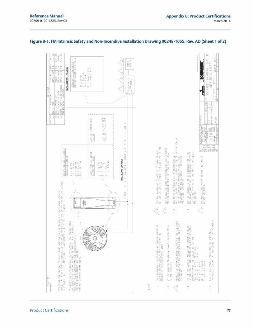
Reference Manual 00809-0100-4825, Rev CB
Appendix B: Product CertificationsMarch 2014
73Product Certifications
Figure B-1. FM Intrinsic Safety and Non-Incendive Installation Drawing 00248-1055, Rev. AD (Sheet 1 of 2)
Ele
ctro
nic
Mas
ter -
PR
INTE
D C
OP
IES
AR
E U
NC
ON
TRO
LLE
D -
Ros
emou
nt P
ropr
ieta
ry
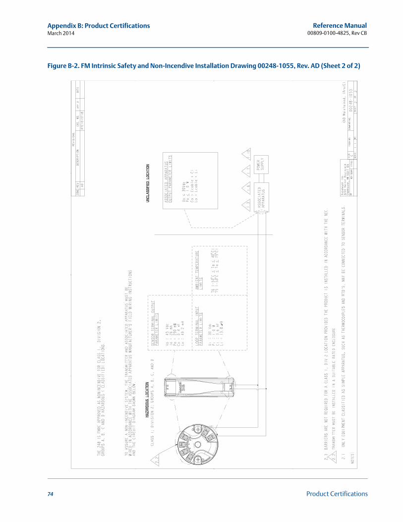
Reference Manual00809-0100-4825, Rev CB
Appendix B: Product CertificationsMarch 2014
74 Product Certifications
Figure B-2. FM Intrinsic Safety and Non-Incendive Installation Drawing 00248-1055, Rev. AD (Sheet 2 of 2)
Ele
ctro
nic
Mas
ter -
PR
INTE
D C
OP
IES
AR
E U
NC
ON
TRO
LLE
D -
Ros
emou
nt P
ropr
ieta
ry
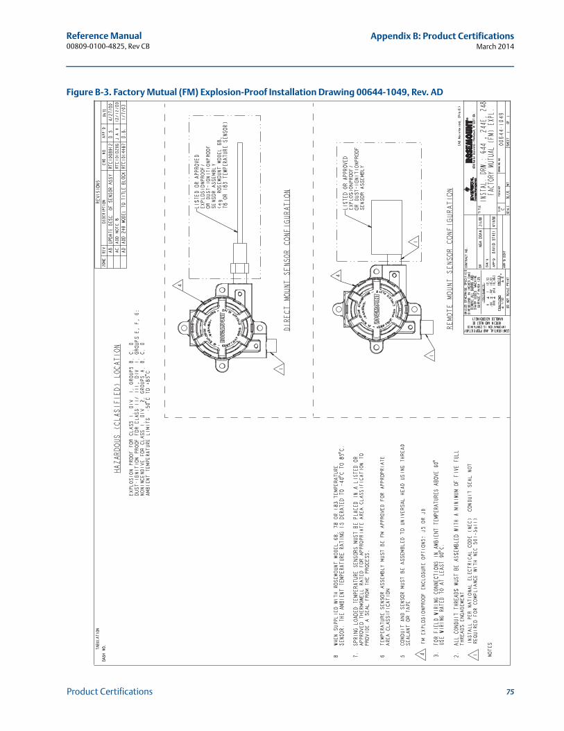
Reference Manual 00809-0100-4825, Rev CB
Appendix B: Product CertificationsMarch 2014
75Product Certifications
Figure B-3. Factory Mutual (FM) Explosion-Proof Installation Drawing 00644-1049, Rev. AD
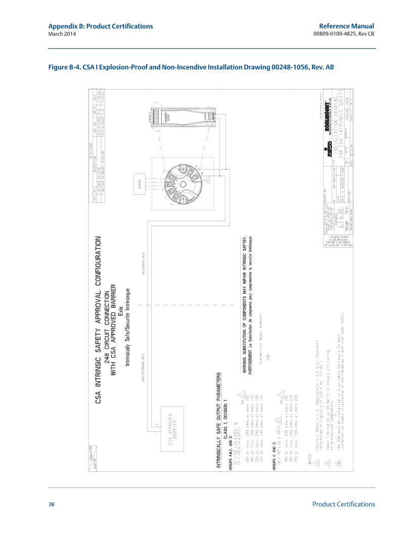
Reference Manual00809-0100-4825, Rev CB
Appendix B: Product CertificationsMarch 2014
76 Product Certifications
Figure B-4. CSA I Explosion-Proof and Non-Incendive Installation Drawing 00248-1056, Rev. AB
Ele
ctro
nic
Mas
ter -
PR
INTE
D C
OP
IES
AR
E U
NC
ON
TRO
LLE
D -
Ros
emou
nt P
ropr
ieta
ry
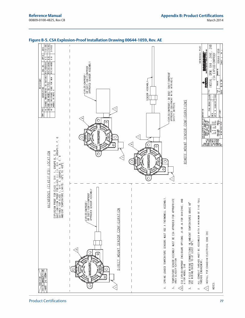
Reference Manual 00809-0100-4825, Rev CB
Appendix B: Product CertificationsMarch 2014
77Product Certifications
Figure B-5. CSA Explosion-Proof Installation Drawing 00644-1059, Rev. AE
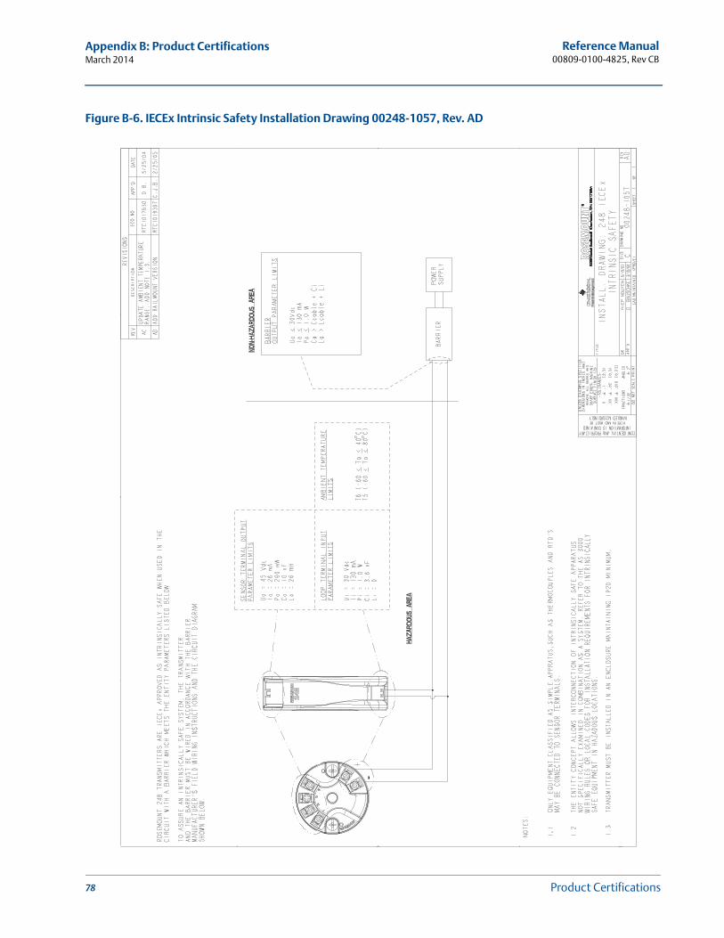
Reference Manual00809-0100-4825, Rev CB
Appendix B: Product CertificationsMarch 2014
78 Product Certifications
Figure B-6. IECEx Intrinsic Safety Installation Drawing 00248-1057, Rev. AD
Ele
ctro
nic
Mas
ter -
PR
INTE
D C
OP
IES
AR
E U
NC
ON
TRO
LLE
D -
Ros
emou
nt P
ropr
ieta
ry
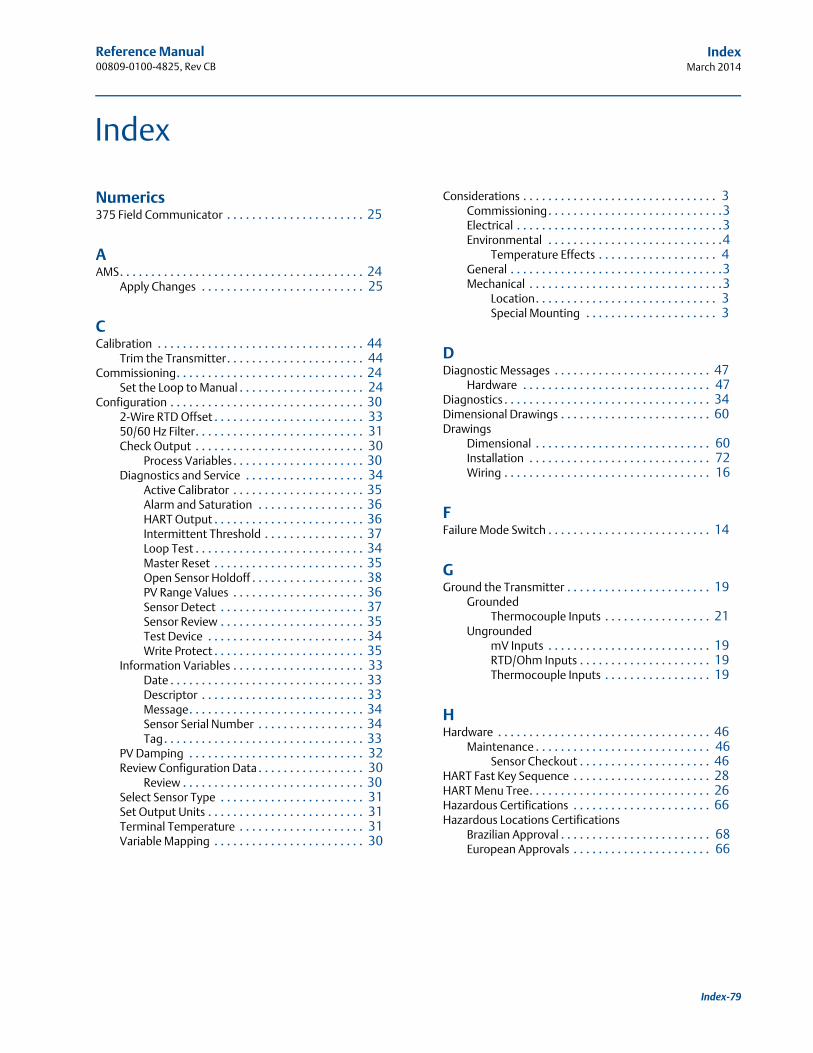
Reference Manual 00809-0100-4825, Rev CB
IndexMarch 2014
Index
Numerics375 Field Communicator . . . . . . . . . . . . . . . . . . . . . . 25
AAMS. . . . . . . . . . . . . . . . . . . . . . . . . . . . . . . . . . . . . . . 24
Apply Changes . . . . . . . . . . . . . . . . . . . . . . . . . . 25
CCalibration . . . . . . . . . . . . . . . . . . . . . . . . . . . . . . . . . 44
Trim the Transmitter. . . . . . . . . . . . . . . . . . . . . . 44Commissioning. . . . . . . . . . . . . . . . . . . . . . . . . . . . . . 24
Set the Loop to Manual . . . . . . . . . . . . . . . . . . . . 24Configuration . . . . . . . . . . . . . . . . . . . . . . . . . . . . . . . 30
2-Wire RTD Offset . . . . . . . . . . . . . . . . . . . . . . . . 3350/60 Hz Filter. . . . . . . . . . . . . . . . . . . . . . . . . . . 31Check Output . . . . . . . . . . . . . . . . . . . . . . . . . . . 30
Process Variables. . . . . . . . . . . . . . . . . . . . . 30Diagnostics and Service . . . . . . . . . . . . . . . . . . . 34
Active Calibrator . . . . . . . . . . . . . . . . . . . . . 35Alarm and Saturation . . . . . . . . . . . . . . . . . 36HART Output . . . . . . . . . . . . . . . . . . . . . . . . 36Intermittent Threshold . . . . . . . . . . . . . . . . 37Loop Test . . . . . . . . . . . . . . . . . . . . . . . . . . . 34Master Reset . . . . . . . . . . . . . . . . . . . . . . . . 35Open Sensor Holdoff . . . . . . . . . . . . . . . . . . 38PV Range Values . . . . . . . . . . . . . . . . . . . . . 36Sensor Detect . . . . . . . . . . . . . . . . . . . . . . . 37Sensor Review . . . . . . . . . . . . . . . . . . . . . . . 35Test Device . . . . . . . . . . . . . . . . . . . . . . . . . 34Write Protect . . . . . . . . . . . . . . . . . . . . . . . . 35
Information Variables . . . . . . . . . . . . . . . . . . . . . 33Date . . . . . . . . . . . . . . . . . . . . . . . . . . . . . . . 33Descriptor . . . . . . . . . . . . . . . . . . . . . . . . . . 33Message. . . . . . . . . . . . . . . . . . . . . . . . . . . . 34Sensor Serial Number . . . . . . . . . . . . . . . . . 34Tag. . . . . . . . . . . . . . . . . . . . . . . . . . . . . . . . 33
PV Damping . . . . . . . . . . . . . . . . . . . . . . . . . . . . 32Review Configuration Data . . . . . . . . . . . . . . . . . 30
Review . . . . . . . . . . . . . . . . . . . . . . . . . . . . . 30Select Sensor Type . . . . . . . . . . . . . . . . . . . . . . . 31Set Output Units . . . . . . . . . . . . . . . . . . . . . . . . . 31Terminal Temperature . . . . . . . . . . . . . . . . . . . . 31Variable Mapping . . . . . . . . . . . . . . . . . . . . . . . . 30
Considerations . . . . . . . . . . . . . . . . . . . . . . . . . . . . . . . 3Commissioning. . . . . . . . . . . . . . . . . . . . . . . . . . . .3Electrical . . . . . . . . . . . . . . . . . . . . . . . . . . . . . . . . .3Environmental . . . . . . . . . . . . . . . . . . . . . . . . . . . .4
Temperature Effects . . . . . . . . . . . . . . . . . . . 4General . . . . . . . . . . . . . . . . . . . . . . . . . . . . . . . . . .3Mechanical . . . . . . . . . . . . . . . . . . . . . . . . . . . . . . .3
Location. . . . . . . . . . . . . . . . . . . . . . . . . . . . . 3Special Mounting . . . . . . . . . . . . . . . . . . . . . 3
DDiagnostic Messages . . . . . . . . . . . . . . . . . . . . . . . . . 47
Hardware . . . . . . . . . . . . . . . . . . . . . . . . . . . . . . 47Diagnostics . . . . . . . . . . . . . . . . . . . . . . . . . . . . . . . . . 34Dimensional Drawings . . . . . . . . . . . . . . . . . . . . . . . . 60Drawings
Dimensional . . . . . . . . . . . . . . . . . . . . . . . . . . . . 60Installation . . . . . . . . . . . . . . . . . . . . . . . . . . . . . 72Wiring . . . . . . . . . . . . . . . . . . . . . . . . . . . . . . . . . 16
FFailure Mode Switch . . . . . . . . . . . . . . . . . . . . . . . . . . 14
GGround the Transmitter . . . . . . . . . . . . . . . . . . . . . . . 19
GroundedThermocouple Inputs . . . . . . . . . . . . . . . . . 21
UngroundedmV Inputs . . . . . . . . . . . . . . . . . . . . . . . . . . 19RTD/Ohm Inputs . . . . . . . . . . . . . . . . . . . . . 19Thermocouple Inputs . . . . . . . . . . . . . . . . . 19
HHardware . . . . . . . . . . . . . . . . . . . . . . . . . . . . . . . . . . 46
Maintenance . . . . . . . . . . . . . . . . . . . . . . . . . . . . 46Sensor Checkout . . . . . . . . . . . . . . . . . . . . . 46
HART Fast Key Sequence . . . . . . . . . . . . . . . . . . . . . . 28HART Menu Tree. . . . . . . . . . . . . . . . . . . . . . . . . . . . . 26Hazardous Certifications . . . . . . . . . . . . . . . . . . . . . . 66Hazardous Locations Certifications
Brazilian Approval . . . . . . . . . . . . . . . . . . . . . . . . 68European Approvals . . . . . . . . . . . . . . . . . . . . . . 66
Index-79
Reference Manual00809-0100-4825, Rev CB
IndexMarch 2014
Index-80
IInstallation
Asia Pacific . . . . . . . . . . . . . . . . . . . . . . . . . . . . . 10European. . . . . . . . . . . . . . . . . . . . . . . . . . . . . . . 10Flowchart . . . . . . . . . . . . . . . . . . . . . . . . . . . . . . . .8Head Mount
DIN Plate Style Sensor . . . . . . . . . . . . . . . . . 10Threaded Sensor . . . . . . . . . . . . . . . . . . . . . 11
North American . . . . . . . . . . . . . . . . . . . . . . . . . 11Rail mount transmitters . . . . . . . . . . . . . . . . . . . 13
Integral mount sensor. . . . . . . . . . . . . . . . . 12Threaded sensor . . . . . . . . . . . . . . . . . . . . . 13
South American . . . . . . . . . . . . . . . . . . . . . . . . . 11Installation Drawings . . . . . . . . . . . . . . . . . . . . . . . . . 72
MModel 275 HART Communicator
Check Output . . . . . . . . . . . . . . . . . . . . . . . . . . . 30Configuration . . . . . . . . . . . . . . . . . . . . . . . . . . . 30Diagnostics and Service . . . . . . . . . . . . . . . . . . . 34Fast Key Sequence . . . . . . . . . . . . . . . . . . . . . . . 28HART Menu Tree. . . . . . . . . . . . . . . . . . . . . . . . . 26Information Variables . . . . . . . . . . . . . . . . . . . . . 33Review Configuration Data. . . . . . . . . . . . . . . . . 30
Mounting . . . . . . . . . . . . . . . . . . . . . . . . . . . . . . . . . . . .9To a DIN Rail . . . . . . . . . . . . . . . . . . . . . . . . . . . . . .9
Multidrop Communication . . . . . . . . . . . . . . . . . . . . 39
OOverview . . . . . . . . . . . . . . . . . . . . . . . . . . . . . . . . . . . .2
Manual . . . . . . . . . . . . . . . . . . . . . . . . . . . . . . . . . .2Transmitter . . . . . . . . . . . . . . . . . . . . . . . . . . . . . . .2
PPower Supply . . . . . . . . . . . . . . . . . . . . . . . . . . . . . . . 18
Grounding. . . . . . . . . . . . . . . . . . . . . . . . . . . . . . 19Surges . . . . . . . . . . . . . . . . . . . . . . . . . . . . . . . . . 19Transients . . . . . . . . . . . . . . . . . . . . . . . . . . . . . . 19
RReturn of Materials . . . . . . . . . . . . . . . . . . . . . . . . . . . . .5
SSensor Connections . . . . . . . . . . . . . . . . . . . . . . . . . . 16
Millivolt Inputs . . . . . . . . . . . . . . . . . . . . . . . . . . 16Ohm Inputs . . . . . . . . . . . . . . . . . . . . . . . . . . . . . 17RTD Inputs . . . . . . . . . . . . . . . . . . . . . . . . . . . . . 17Thermocouple Inputs . . . . . . . . . . . . . . . . . . . . . 16
Sensor Wiring Diagrams. . . . . . . . . . . . . . . . . . . . . . . 16Set the Loop to Manual . . . . . . . . . . . . . . . . . . . . . . . 24
SpecificationsASTME 230 Thermocouples
Construction . . . . . . . . . . . . . . . . . . . . . . . . 58Insulation Resistance . . . . . . . . . . . . . . . . . 58Lead Wires. . . . . . . . . . . . . . . . . . . . . . . . . . 58
FunctionalAlarm Levels . . . . . . . . . . . . . . . . . . . . . . . . 52Failure Mode . . . . . . . . . . . . . . . . . . . . . . . . 52Humidity Limits. . . . . . . . . . . . . . . . . . . . . . 51Inputs . . . . . . . . . . . . . . . . . . . . . . . . . . . . . 51Isolation . . . . . . . . . . . . . . . . . . . . . . . . . . . 51NAMUR . . . . . . . . . . . . . . . . . . . . . . . . . . . . 51Output . . . . . . . . . . . . . . . . . . . . . . . . . . . . 51Power Supply . . . . . . . . . . . . . . . . . . . . . . . 51Saturation Levels. . . . . . . . . . . . . . . . . . . . . 52Temperature Limits . . . . . . . . . . . . . . . . . . 52Transient Protection . . . . . . . . . . . . . . . . . . 52Turn-on Time . . . . . . . . . . . . . . . . . . . . . . . 52Update Rate . . . . . . . . . . . . . . . . . . . . . . . . 52
IEC 584 ThermocouplesConstruction . . . . . . . . . . . . . . . . . . . . . . . . 57Insulation Resistance . . . . . . . . . . . . . . . . . 57Lead Wires. . . . . . . . . . . . . . . . . . . . . . . . . . 57
PerformanceAmbient Temperature . . . . . . . . . . . . . . . . 55CE Mark . . . . . . . . . . . . . . . . . . . . . . . . . . . . 54EMC Standard . . . . . . . . . . . . . . . . . . . . . . . 54Power Supply Effect . . . . . . . . . . . . . . . . . . 54Self Calibration . . . . . . . . . . . . . . . . . . . . . . 54Sensor Connections . . . . . . . . . . . . . . . . . . 55Stability . . . . . . . . . . . . . . . . . . . . . . . . . . . . 54Vibration Effect . . . . . . . . . . . . . . . . . . . . . . 54
PhysicalEnclosure Ratings . . . . . . . . . . . . . . . . . . . . 54HART Connections . . . . . . . . . . . . . . . . . . . 53Materials of Construction . . . . . . . . . . . . . . 53Mounting . . . . . . . . . . . . . . . . . . . . . . . . . . 53Weight . . . . . . . . . . . . . . . . . . . . . . . . . . . . 53
RTDAccuracy . . . . . . . . . . . . . . . . . . . . . . . . . . . 58Immersion Error . . . . . . . . . . . . . . . . . . . . . 59Insulation Resistance . . . . . . . . . . . . . . . . . 59Lead Wires. . . . . . . . . . . . . . . . . . . . . . . . . . 59Self Heating. . . . . . . . . . . . . . . . . . . . . . . . . 58Sensor Type. . . . . . . . . . . . . . . . . . . . . . . . . 58Sheath Material. . . . . . . . . . . . . . . . . . . . . . 59Temperature Range . . . . . . . . . . . . . . . . . . 58Thermal Response Time . . . . . . . . . . . . . . . 59
Sensor . . . . . . . . . . . . . . . . . . . . . . . . . . . . . . . . . 57RTD . . . . . . . . . . . . . . . . . . . . . . . . . . . . . . . 58Thermocouples. . . . . . . . . . . . . . . . . . . . . . 57Thermowells . . . . . . . . . . . . . . . . . . . . . . . . 59
ThermowellsConstruction . . . . . . . . . . . . . . . . . . . . . . . . 59Materials . . . . . . . . . . . . . . . . . . . . . . . . . . . 59
Reference Manual 00809-0100-4825, Rev CB
IndexMarch 2014
Transmitter . . . . . . . . . . . . . . . . . . . . . . . . . . . . . 51Functional . . . . . . . . . . . . . . . . . . . . . . . . . . 51Performance . . . . . . . . . . . . . . . . . . . . . . . . 54Physical . . . . . . . . . . . . . . . . . . . . . . . . . . . . 53
Surges . . . . . . . . . . . . . . . . . . . . . . . . . . . . . . . . . . . . . 19Switches . . . . . . . . . . . . . . . . . . . . . . . . . . . . . . . . . . . 14
Failure Mode . . . . . . . . . . . . . . . . . . . . . . . . . . . . 14
TTransients . . . . . . . . . . . . . . . . . . . . . . . . . . . . . . . . . . 19Trim the Transmitter . . . . . . . . . . . . . . . . . . . . . . . . . 44
Output Trim . . . . . . . . . . . . . . . . . . . . . . . . . . . . 46Scaled Output Trim . . . . . . . . . . . . . . . . . . . . . . . 46Sensor Input Trim . . . . . . . . . . . . . . . . . . . . . . . . 44
WWiring . . . . . . . . . . . . . . . . . . . . . . . . . . . . . . . . . . . . . 15
Loop Diagram . . . . . . . . . . . . . . . . . . . . . . . . . . . 16Sensor Wiring Diagrams . . . . . . . . . . . . . . . . . . . 16
Index-81


Reference Manual00809-0100-4825, Rev CB
March 2014
Standard Terms and Conditions of Sale can be found at www.rosemount.com/terms_of_saleThe Emerson logo is a trademark and service mark of Emerson Electric Co.Rosemount. the Rosemount logotype, and SMART FAMILY are registered trademarks of Rosemount Inc.Coplanar is a trademark of Rosemount Inc.Halocarbon is a trademark of the Halocarbon Products Corporation.o.Fluorinert is a registered trademark of Minnesota Mining and Manufacturing Company Corporation
Syltherm 800 and D.C. 200 are registered trademarks of Dow Corning Corporation.Neobee M-20 is a registered trademark of PVO International, Inc.HART is a registered trademark of the HART Communication Foundation.Foundation fieldbus is a registered trademark of the Fieldbus Foundation.All other marks are the property of their respective owners.© March 2014 Rosemount, Inc. All rights reserved.
Emerson Process Management GmbH & Co.Argelsrieder Feld 382234 WesslingGermanyTel 49 (8153) 9390Fax 49 (8153) 939172
Emerson Process Management Asia Pacific Private Limited1 Pandan CrescentSingapore 128461T (65) 6777 8211F (65) 6777 [email protected]
Beijing Rosemount Far EastInstrument Co., LimitedNo. 6 North Street, Hepingli, Dong Cheng DistrictBeijing 100013, ChinaT (86) (10) 6428 2233F (86) (10) 6422 8586
Emerson Process ManagementRosemount Measurement8200 Market BoulevardChanhassen MN 55317 USATel (USA) 1 800 999 9307Tel (International) +1 952 906 8888Fax +1 952 906 8889
Emerson Process Management Latin America1300 Concord Terrace, Suite 400Sunrise Florida 33323 USATel + 1 954 846 5030