Embed Size (px)
Citation preview
2- or 4-pipe configurable
Dual or Single Setpoint
7 Day Programmable
3 Occupied, 1 Unoccupied
Very easy to program
Large, easy to read display
Thermoglow Backlight
Auto-Changeover
Locking Keypad
Override capable
Meets California Title 24
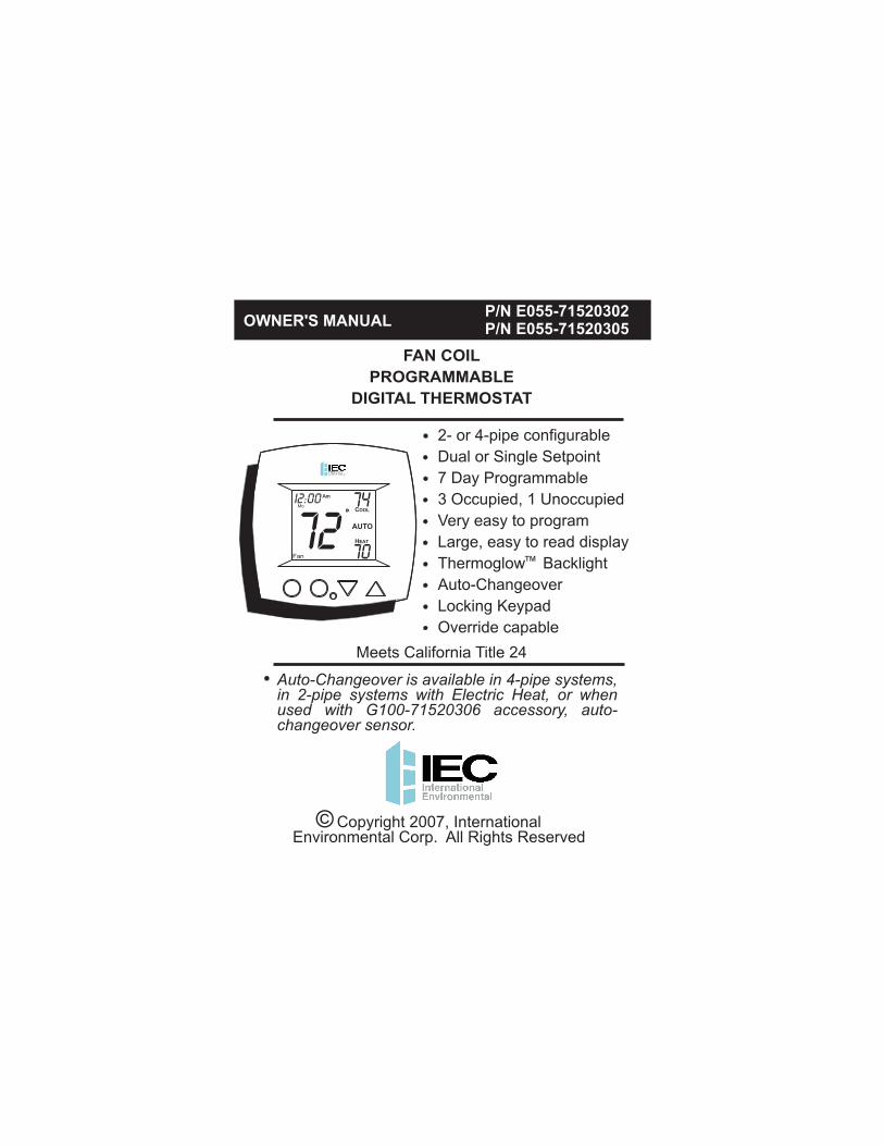
OWNER'S MANUALP/N E055-71520302P/N E055-71520305
Auto-Changeover is available in 4-pipe systems,in 2-pipe systems with Electric Heat, or when used with G100-71520306 accessory, auto-changeover sensor.
7274
70
Am
COOL
HEAT
AUTO
MoI2:00
FAN COIL
PROGRAMMABLE
DIGITAL THERMOSTAT
Copyright 2007, InternationalEnvironmental Corp. All Rights Reserved
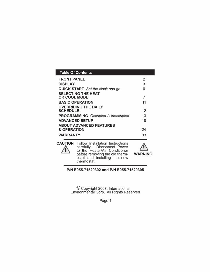
P/N E055-71520302 and P/N E055-71520305
Table Of Contents
FRONT PANEL
DISPLAY
QUICK START Set the clock and go
BASIC OPERATION
PROGRAMMING Occupied / Unoccupied
OVERRIDING THE DAILYSCHEDULE
ADVANCED SETUP
ABOUT ADVANCED FEATURES& OPERATION
WARRANTY
2
3
6
11
12
18
24
33
Page 1
13
CAUTION
WARNING
SELECTING THE HEATOR COOL MODE 7
Follow Installation Instructionscarefully. Disconnect Power to the Heater/Air Conditionerbefore removing the old therm-ostat and installing the new thermostat.
Copyright 2007, InternationalEnvironmental Corp. All Rights Reserved
7274
70
Am
COOL
HEAT
AUTO
MoI2:00
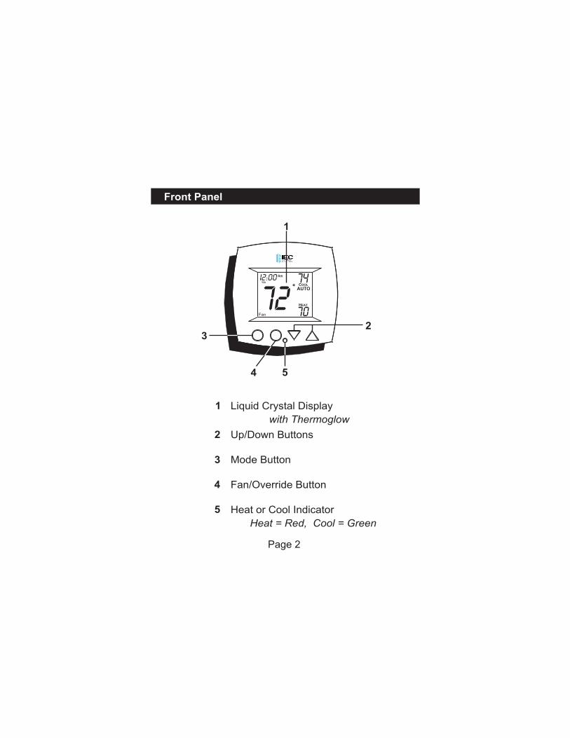
Front Panel
Page 2
Liquid Crystal Display
with Thermoglow
Up/Down Buttons
Mode Button
Fan/Override Button
Heat or Cool Indicator
Heat = Red, Cool = Green
1
1
2
3
4
5
23
4 5
Display
Page 3
OUTSIDE
1
2
3
4
4
1
1
1
2
3
4
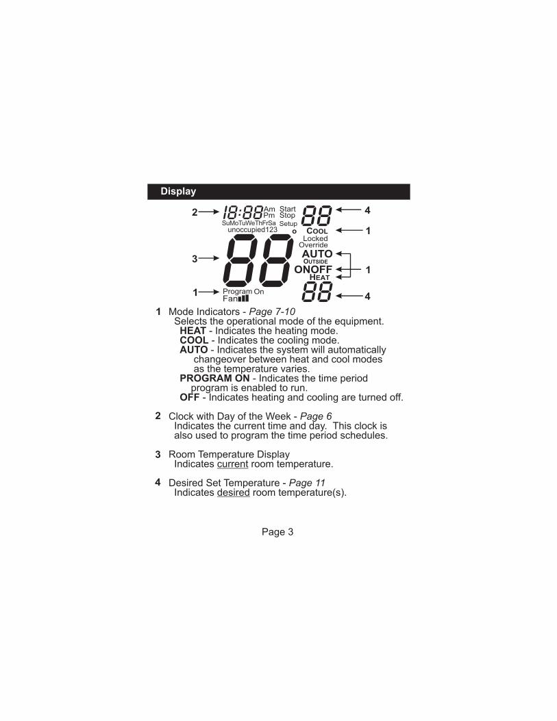
Mode Indicators - Page 7-10 Selects the operational mode of the equipment. HEAT - Indicates the heating mode. COOL - Indicates the cooling mode. AUTO - Indicates the system will automatically changeover between heat and cool modes as the temperature varies. PROGRAM ON - Indicates the time period program is enabled to run. OFF - Indicates heating and cooling are turned off.
Clock with Day of the Week - Page 6 Indicates the current time and day. This clock is also used to program the time period schedules.
Room Temperature Display Indicates current room temperature.
Desired Set Temperature - Page 11 Indicates desired room temperature(s).
Display
88unoccupied
AmPm
SuMoTuWeThFrSa123
I2:00
Page 4
StopStart
Setup 88
88
COOL
HEAT
OverrideLocked
AUTOOUTSIDE
67
8
5
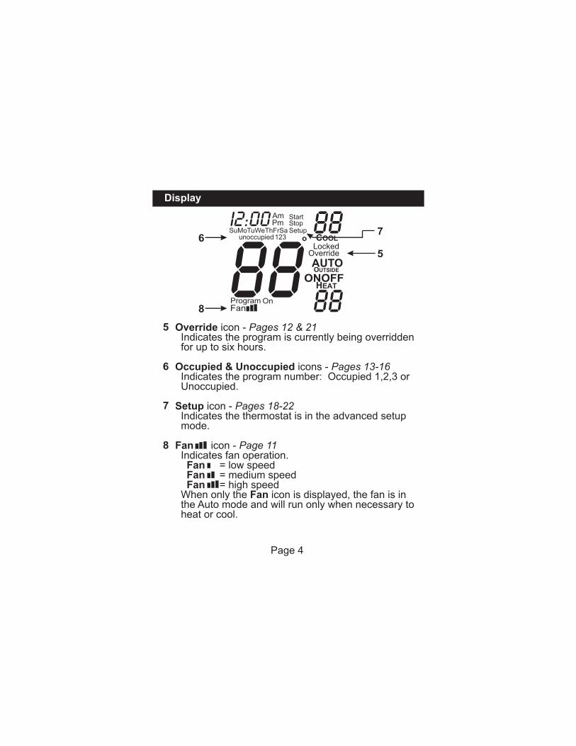
Override icon - Pages 12 & 21 Indicates the program is currently being overridden for up to six hours.
Occupied & Unoccupied icons - Pages 13-16 Indicates the program number: Occupied 1,2,3 or Unoccupied.
Setup icon - Pages 18-22 Indicates the thermostat is in the advanced setup mode.
Fan icon - Page 11 Indicates fan operation. Fan = low speed Fan = medium speed Fan = high speed When only the Fan icon is displayed, the fan is in the Auto mode and will run only when necessary to heat or cool.
5
6
7
8
Display
88unoccupied
AmPm
SuMoTuWeThFrSa123
I2:00
Page 5
StopStart
Setup 88
88
COOL
HEAT
OverrideLocked
AUTOOUTSIDE
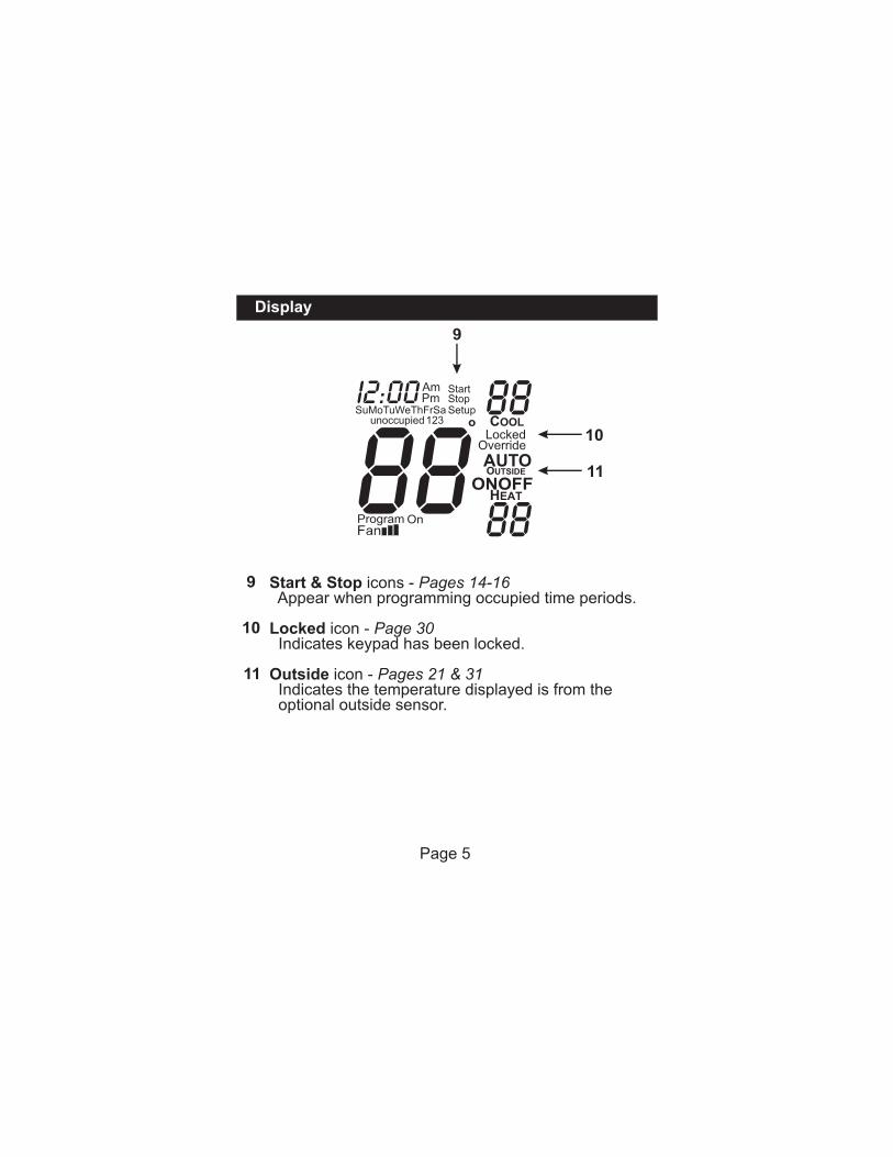
Start & Stop icons - Pages 14-16 Appear when programming occupied time periods.
Locked icon - Page 30 Indicates keypad has been locked.
Outside icon - Pages 21 & 31 Indicates the temperature displayed is from the optional outside sensor.
9
10
11
9
10
11
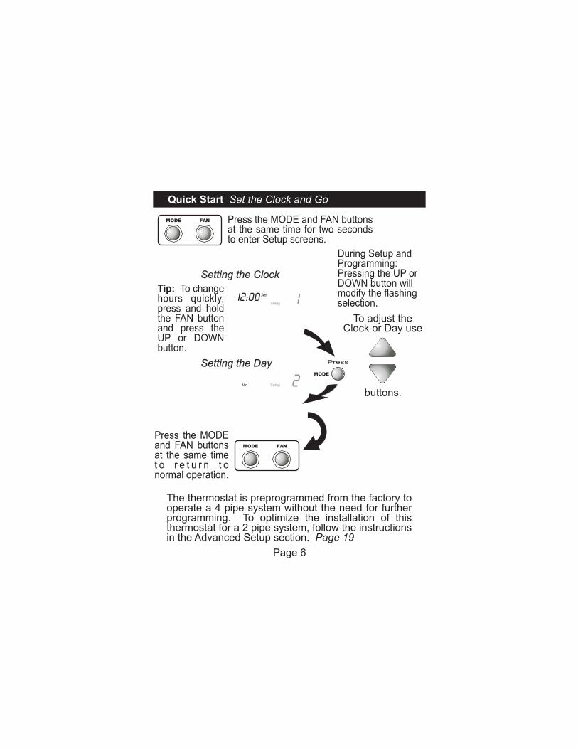
The thermostat is preprogrammed from the factory to operate a 4 pipe system without the need for further programming. To optimize the installation of this thermostat for a 2 pipe system, follow the instructions in the Advanced Setup section. Page 19
Press the MODE and FAN buttons at the same time for two seconds to enter Setup screens.
Quick Start Set the Clock and Go
Press
MODE
Setting the Clock
Setting the Day
Am
SetupI2:00
SetupMo
MODE FAN
MODE FAN
Press the MODE and FAN buttons at the same time t o r e t u r n t o normal operation.
Page 6
To adjust theClock or Day use
buttons.
During Setup andProgramming:Pressing the UP orDOWN button willmodify the flashingselection.
Tip: To change hours quickly,press and holdthe FAN buttonand press theUP or DOWNbutton.
70 68
Pm
HEAT
MoI2:00
7076Pm
COOL MoI2:00
7076
68
Pm
COOL
HEAT
AUTO
MoI2:00
7076
68
occupied
ProgramOn
Pm
COOL
HEAT
Mo1
I2:00
70Pm
OFF
MoI2:00
Press
MODE
Press
Press
Press
MODE
MODE
MODE
Page 7
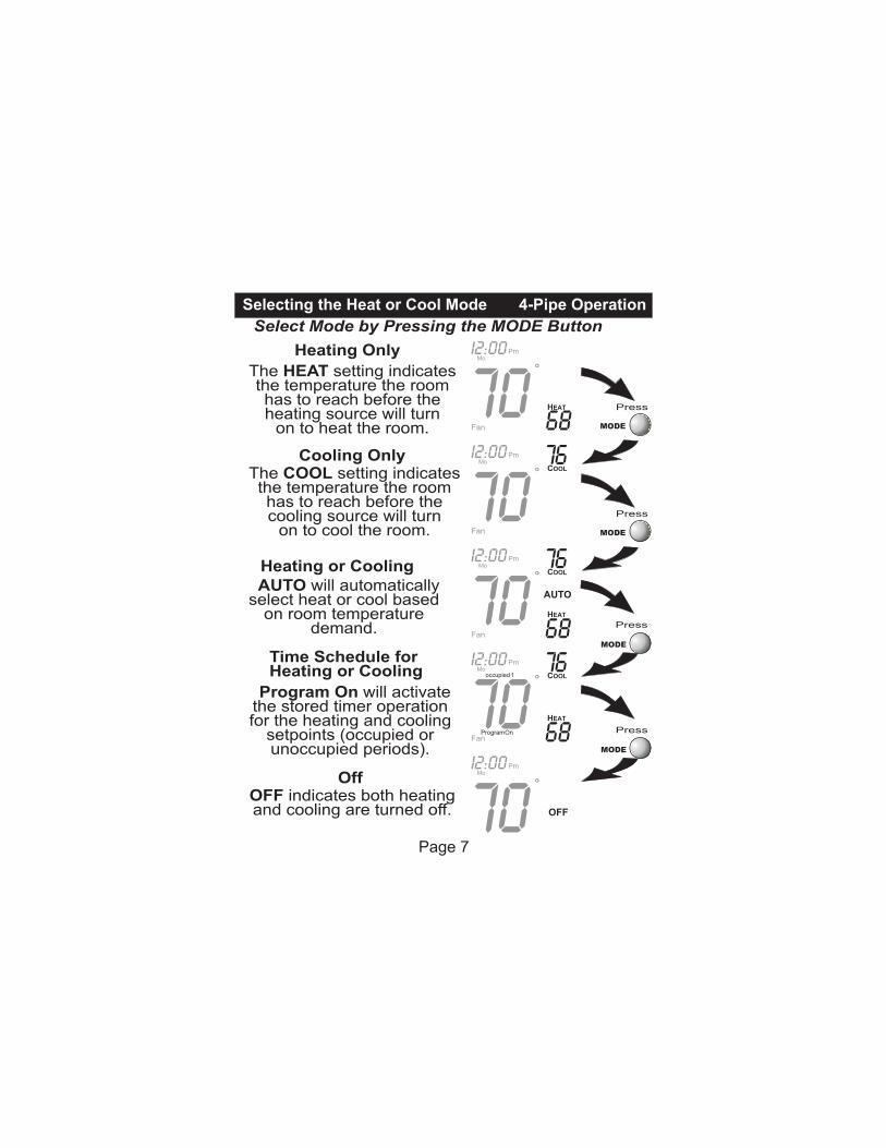
The HEAT setting indicates the temperature the room has to reach before the heating source will turn
on to heat the room.
Heating Only
The COOL setting indicatesthe temperature the room has to reach before the cooling source will turn
on to cool the room.
Cooling Only
OFF indicates both heatingand cooling are turned off.
Off
AUTO will automatically select heat or cool based
on room temperature demand.
Heating or Cooling
Time Schedule for Heating or Cooling
Program On will activate the stored timer operation for the heating and cooling
setpoints (occupied or unoccupied periods).
Select Mode by Pressing the MODE Button
Selecting the Heat or Cool Mode 4-Pipe Operation

Heat Only
Step #6 = 1 in the Advanced Setup section, page 19.
70 68
Pm
HEAT
MoI2:00
70 68
occupied
ProgramOn
Pm
HEAT
Mo1
I2:00
70Pm
OFF
MoI2:00
Press
Press
MODE
MODE
Selecting the Heat or Cool Mode 2-Pipe Operation
The HEAT setting indicates the temperature the room has to reach before the heating source will turn
on to heat the room.
Heating Only
Time Schedule for Heating or Cooling
Program On will activate the stored timer operation for the heating and cooling
setpoints (occupied or unoccupied periods).
OFF indicates both heatingand cooling are turned off.
Off
Page 8
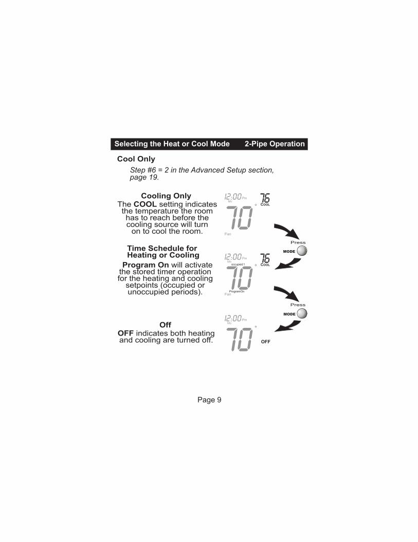
Cool Only
Step #6 = 2 in the Advanced Setup section, page 19.
7076
occupied
ProgramOn
Pm
COOL Mo
1
I2:00
70Pm
OFF
MoI2:00
Press
Press
MODE
MODE
7076Pm
COOL MoI2:00
Selecting the Heat or Cool Mode 2-Pipe Operation
The COOL setting indicatesthe temperature the room has to reach before the cooling source will turn
on to cool the room.
Cooling Only
OFF indicates both heatingand cooling are turned off.
Off
Time Schedule for Heating or Cooling
Program On will activate the stored timer operation for the heating and cooling
setpoints (occupied or unoccupied periods).
Page 9
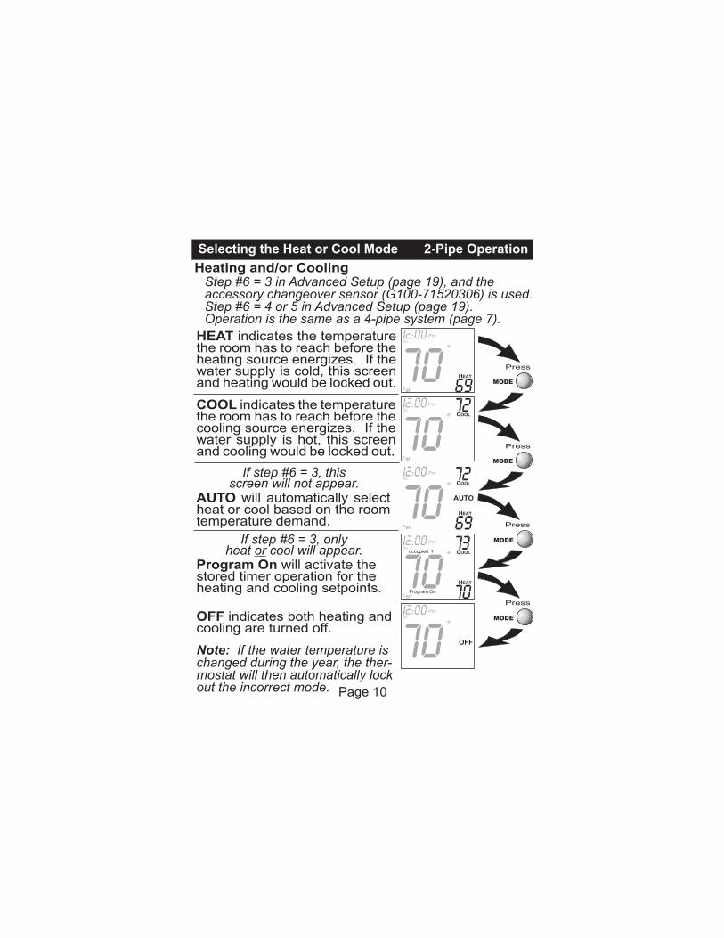
HEAT indicates the temperature the room has to reach before the heating source energizes. If the water supply is cold, this screen and heating would be locked out.
COOL indicates the temperature the room has to reach before the cooling source energizes. If the water supply is hot, this screen and cooling would be locked out.
70I2:00Su
OFF
Press
MODE
Press
Press
Press
MODE
MODE
MODE
Page 10
70I2:00
69
Su
7072I2:00
Su
7073I2:00
70
Suoccupied 1
Note: If the water temperature is changed during the year, the ther-mostat will then automatically lock out the incorrect mode.
Heating and/or CoolingStep #6 = 3 in Advanced Setup (page 19), and the accessory changeover sensor (G100-71520306) is used.Step #6 = 4 or 5 in Advanced Setup (page 19). Operation is the same as a 4-pipe system (page 7).
Selecting the Heat or Cool Mode 2-Pipe Operation
Program On will activate the stored timer operation for the heating and cooling setpoints.
If step #6 = 3, only heat or cool will appear.
7072I2:00
69
SuIf step #6 = 3, this
screen will not appear.AUTO will automatically select heat or cool based on the room temperature demand.
OFF indicates both heating and cooling are turned off.
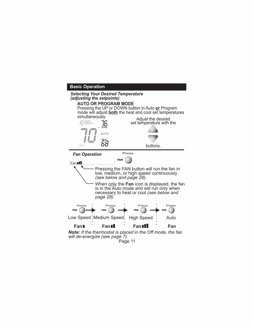
Selecting Your Desired Temperature(adjusting the setpoints)
Basic Operation
7076
68
Pm
COOL
HEAT
AUTO
MoI2:00
AUTO OR PROGRAM MODEPressing the UP or DOWN button in Auto or Program mode will adjust both the heat and cool set temperatures simultaneously.
buttons.
Adjust the desired set temperature with the
Fan Operation Press
FAN
Press
FAN
Press
FAN
Press
FAN
Press
FAN
Low Speed Medium Speed High Speed Auto
Fan
Pressing the FAN button will run the fan in low, medium, or high speed continuously (see below and page 28).
When only the Fan icon is displayed, the fanis in the Auto mode and will run only when necessary to heat or cool (see below and page 28).
Note: If the thermostat is placed in the Off mode, the fan will de-energize (see page 7).
Fan Fan Fan
Page 11
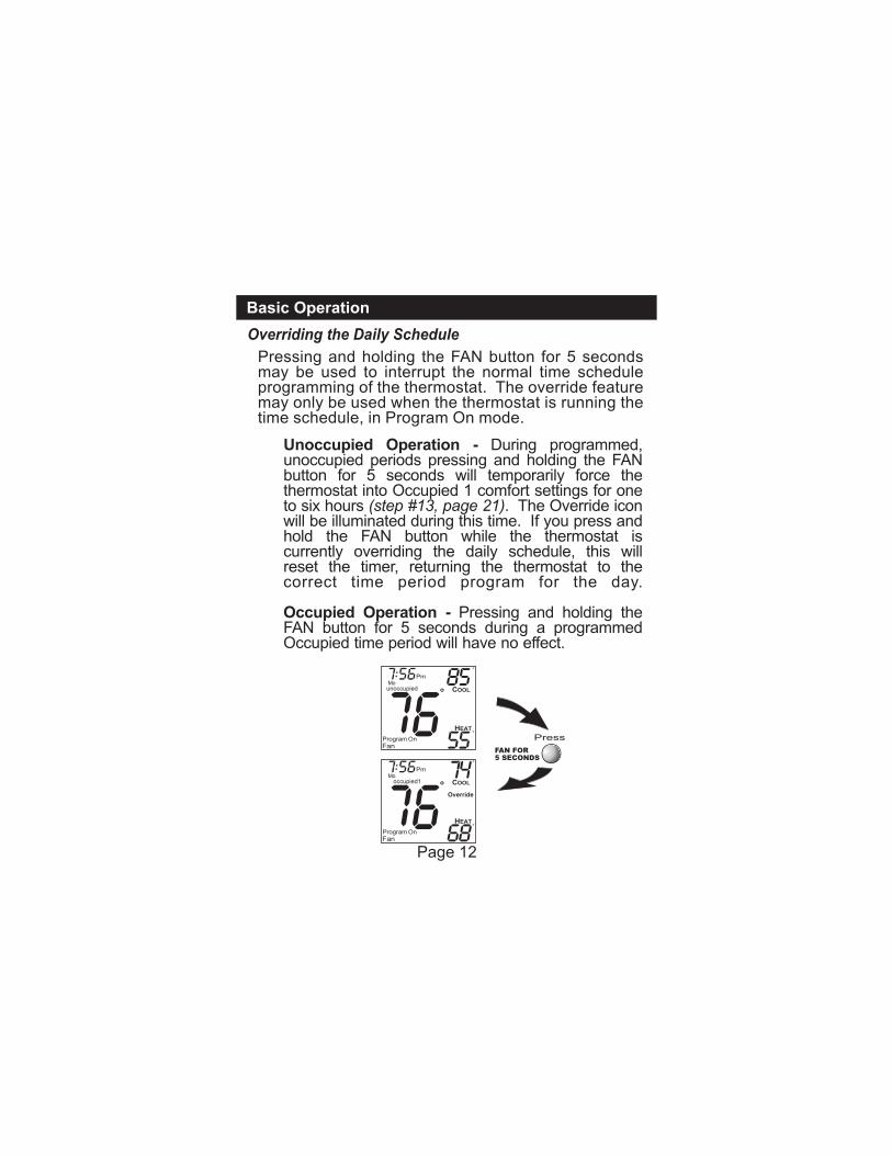
Overriding the Daily Schedule
Basic Operation
Pressing and holding the FAN button for 5 seconds may be used to interrupt the normal time schedule programming of the thermostat. The override feature may only be used when the thermostat is running the time schedule, in Program On mode.
Press
FAN FOR5 SECONDS
7:56
7:56
O
O
85
55
O
O
74
68
Override
Unoccupied Operation - During programmed, unoccupied periods pressing and holding the FAN button for 5 seconds will temporarily force the thermostat into Occupied 1 comfort settings for one to six hours (step #13, page 21). The Override icon will be illuminated during this time. If you press and hold the FAN button while the thermostat is currently overriding the daily schedule, this will reset the timer, returning the thermostat to the correct time period program for the day.
Occupied Operation - Pressing and holding the FAN button for 5 seconds during a programmed Occupied time period will have no effect.
Page 12
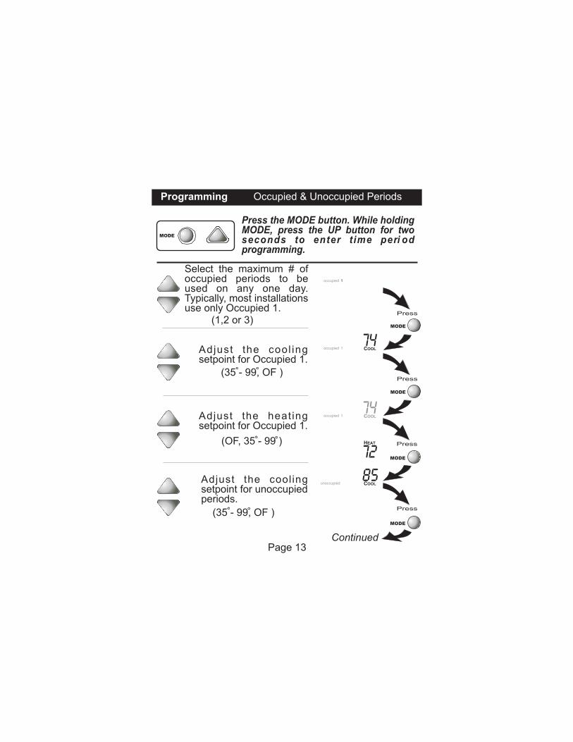
Programming Occupied & Unoccupied Periods
Press
Press
Press
Press
Continued
MODE
MODE
MODE
MODE
occupied 1
74COOL1
74
72
COOL
HEAT
1
85unoccupied COOL
Press the MODE button. While holding MODE, press the UP button for two seconds to enter t ime peri od programming.
MODE
Select the maximum # ofoccupied periods to beused on any one day.Typically, most installationsuse only Occupied 1.
(1,2 or 3)
Adjust the cool ingsetpoint for Occupied 1.
(35 - 99, OF )
Adjust the heat ingsetpoint for Occupied 1.
(OF, 35 - 99 )
occupied
occupied
Adjust the coolingsetpoint for unoccupiedperiods.
(35 - 99, OF )
Page 13
MODE
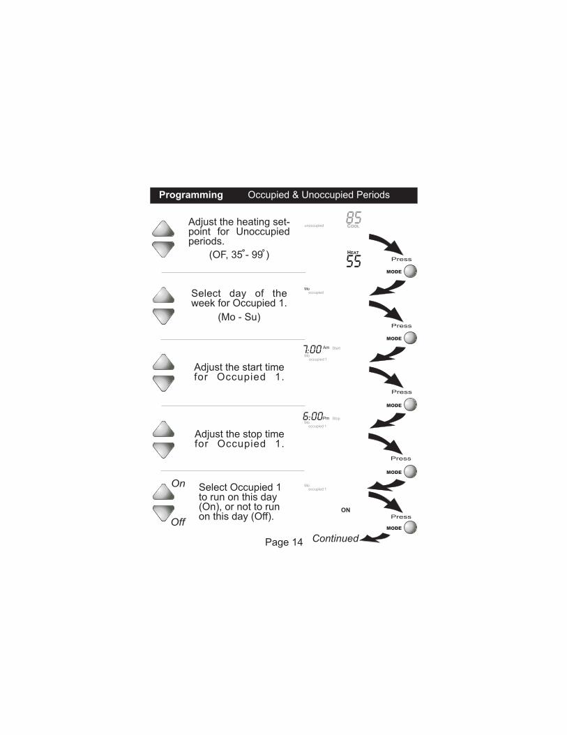
Programming Occupied & Unoccupied Periods
Press
Press
Press
Press
Press
MODE
MODE
MODE
MODE
55
unoccupied
HEAT
Am Start
1
7:00
85COOL
Mo
Mo
Pm Stop
1
6:00 Mo
ON
1
Off
On Mo
Select day of the week for Occupied 1.
(Mo - Su)
Adjust the start timefor Occupied 1.
Adjust the stop timefor Occupied 1.
Select Occupied 1 to run on this day (On), or not to run on this day (Off).
occupied
occupied
occupied
occupied
Page 14
Adjust the heating set-point for Unoccupiedperiods.
(OF, 35 - 99 )
Continued
Programming Occupied & Unoccupied Periods
Press
Press
Press
Continued
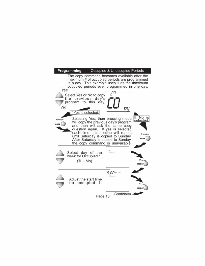
Select Yes or No to copythe prev ious day ’sprogram to this day.
If No is selected:
Selecting Yes, then pressing mode will copy the previous day’s program and then will ask the same copy question again. If yes is selected each time, this routine will repeat until Saturday is copied to Sunday. After Saturday is copied to Sunday, the copy command is unavailable.
The copy command becomes available after the maximum # of occupied periods are programmed in a day. This example uses 1 as the maximum occupied periods ever programmed in one day.
Yes
No
MODE
MODE
MODE
Co Py
Tu
occupied Tu
1
occupied
Am Start
Tu1
9:00
(Tu - Mo)
Select day of the week for Occupied 1.
Adjust the start timefor occupied 1.
Page 15
Press
If Yes is selected:
MODE
Programming Occupied & Unoccupied Periods
Press
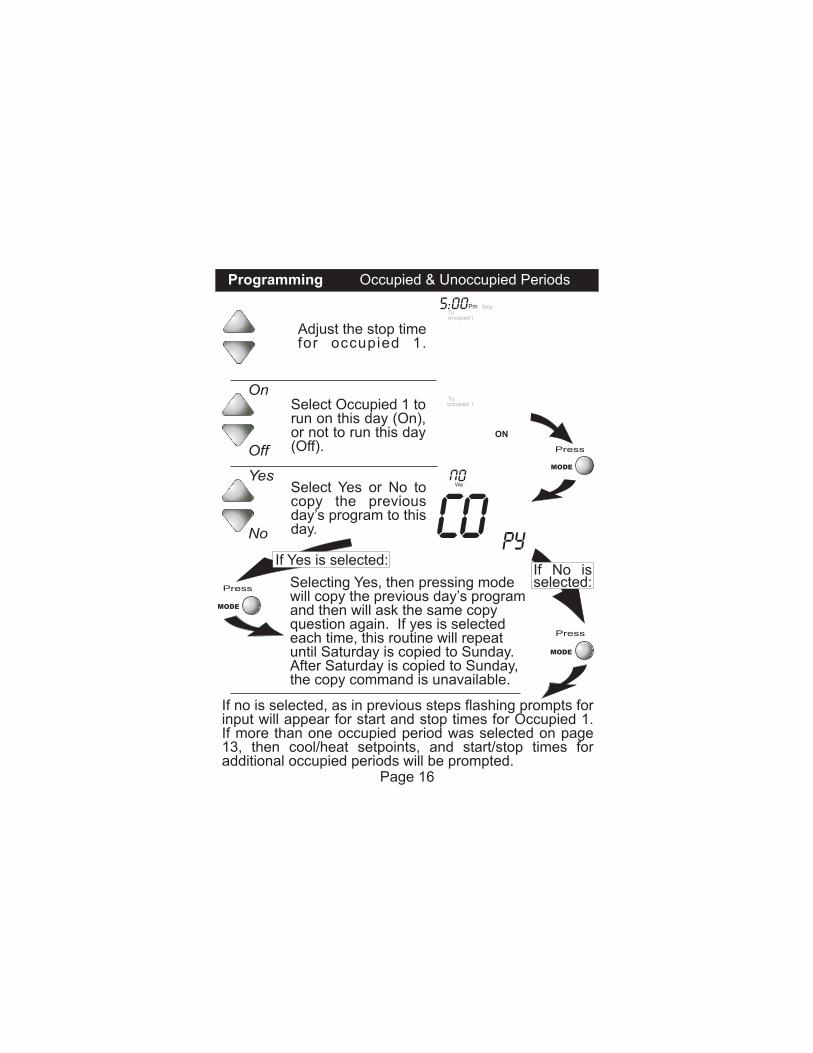
Select Occupied 1 to run on this day (On), or not to run this day (Off).Off
On
Selecting Yes, then pressing mode will copy the previous day’s program and then will ask the same copy question again. If yes is selectedeach time, this routine will repeat until Saturday is copied to Sunday. After Saturday is copied to Sunday, the copy command is unavailable.
If no is selected, as in previous steps flashing prompts forinput will appear for start and stop times for Occupied 1. If more than one occupied period was selected on page 13, then cool/heat setpoints, and start/stop times for additional occupied periods will be prompted.
Select Yes or No to copy the previous day’s program to this day.
Yes
No
Press
MODE
MODE
Press
MODE
Page 16
occupied Tu
1
Co Py
We
ON
occupied
Pm Stop Tu
1
5:00
Adjust the stop timefor occupied 1.
If No is selected:
If Yes is selected:
PROGRAMMING NOTES
You will be prompted to enter both heat and cool setpoints even if the thermostat is configured for heat only, or cool only.
Heat & Cool setpoints for Occupied 1 are the same for each day. Heat & Cool setpoints for Occupied 2 & 3 can be adjusted differently for each day, if desired.
If the start time is set for later than the stop time, the program will run from the start time to midnight and from midnight to the stop time on the same day. For example: 9:00pm start, 8:00am stop, on MTWTF. This program will run from 12:00am MTWTF to 8:00am MTWTF and again from 9:00pm MTWTF to 12:00pm MTWTF.
The Unoccupied settings take effect at all times when: (1) the program is on and (2) the current time is outside a preset occupied period. For this reason start and stop times aren’t necessary for unoccupied.
If the same start and stop times are programmed in foran occupied period, then it will run 24 hours.
If one occupied period starts and stops within another occupied period, the lower occupied # has priority. example: If Occupied 3 is programmed to be “on” 24 hours, and Occupied 2 is programmed to run that day, then Occupied 2 settings will take over from Occupied 3 between Occupied 2 start and stop times.
For
If only 1 Occupied period is selected, the Occupied 2 & 3 steps will be skipped. Further, if only 2 occupieds are selected, the Occupied 3 steps will be skipped.
Programming Occupied & Unoccupied Periods
When the time period programming for Unoccupied is in the Override mode (see page 12), the Heat & Cool setpoints for Occupied 1 are used.
Page 17
Press
Press
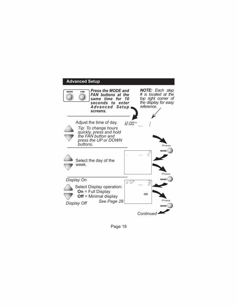
Select Display operation: On = Full Display Off = Minimal display
Select the day of theweek.
Display On
Display Off See Page 28
MODE
MODE
Adjust the time of day.
Tip: To change hours quickly, press and hold the FAN button and press the UP or DOWN buttons.
NOTE: Each step# is located at the top right corner of the display for easy reference.
Press the MODE and FAN buttons at the same time for 10 seconds to enter Advanced Setup screens.
Advanced Setup
MODE FAN
2Setup Mo
IAm
SetupI2:00
3
ON
Setup
Press
MODE
Continued
Page 18
Advanced Setup
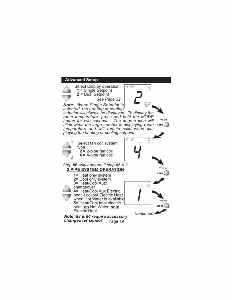
Select fan coil system type: 2 = 2-pipe fan coil 4 = 4-pipe fan coil
4
2
Step #6 only appears if step #5 = 2.2 PIPE SYSTEM OPERATION
1= Heat only system2= Cool only system3= Heat/Cool Auto changeover4= Heat/Cool Aux Electric heat, Lockout Electric Heat when Hot Water is available5= Heat/Cool total electric heat, no Hot Water, only Electric Heat.
Note: #3 & #4 require accessory changeover sensor
4 5Setup
Press
MODE
Press
MODE
Press
MODE
Continued
I 6Setup
Page 19
Select Display operation: 1 = Single Setpoint 2 = Dual Setpoint
See Page 32
setpoint will always be displayed. To display the room temperature, press and hold the MODE button for two seconds. The degree icon will blink when the large number is displaying room temperature and will remain solid when dis-playing the heating or cooling setpoint.
4Setup
2Note: When Single Setpoint is selected, the heating or cooling
Advanced Setup
On
Off
2 9COOL
HEAT
Setup
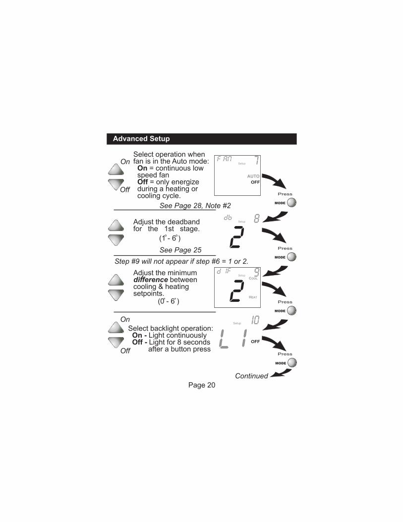
Select backlight operation: On - Light continuously Off - Light for 8 seconds after a button press
Press
MODE
Press
MODE
Press
MODE
Press
MODE
Continued
Setup I0
Step #9 will not appear if step #6 = 1 or 2.
Page 20
2 8SetupAdjust the deadband
for the 1st stage.
(1 - 6 )
See Page 25
On
Off
See Page 28, Note #2
Select operation when fan is in the Auto mode: On = continuous low speed fan Off = only energize during a heating or cooling cycle.
7AUTO
Adjust the minimum difference betweencooling & heatingsetpoints.
(0 - 6 )
Advanced Setup
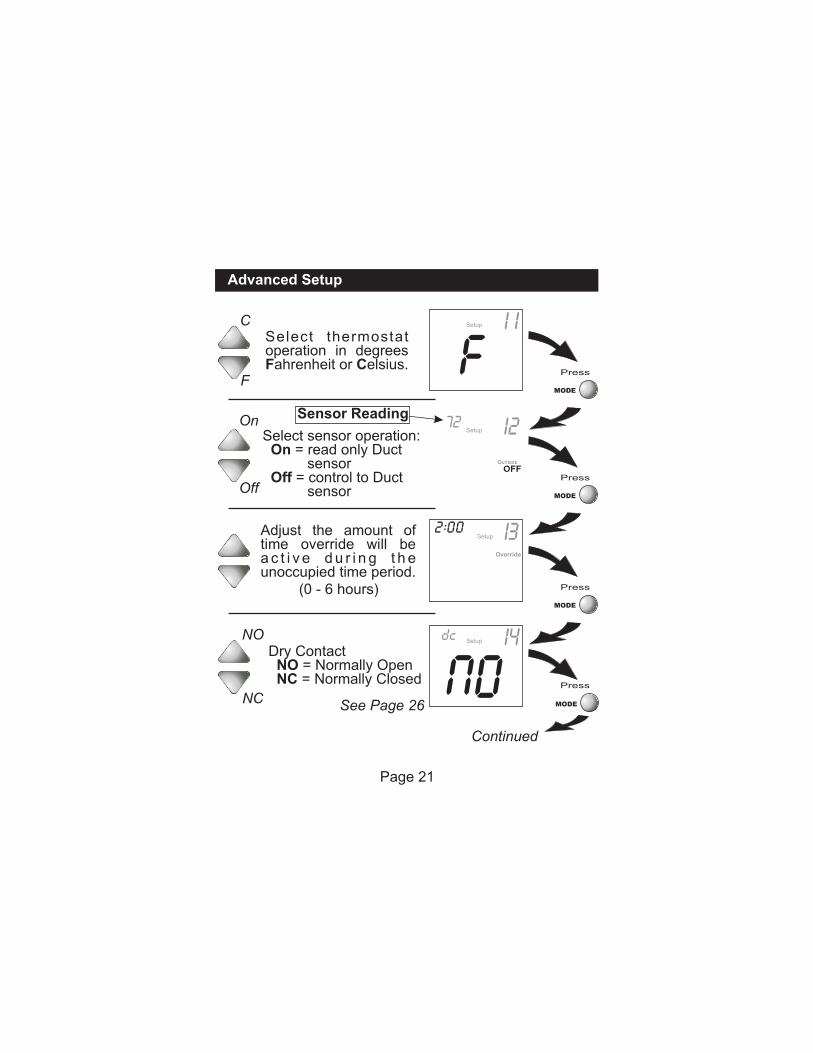
Dry Contact NO = Normally Open NC = Normally Closed
NO
NC
Setup I4
Adjust the amount oftime override will bea c t i v e d u r i n g t h e unoccupied time period.
(0 - 6 hours) Press
MODE
Press
MODE
Override
2 00 I3Setup
See Page 26
Page 21
Press
MODE
Continued
Select sensor operation: On = sensor Off = control to Duct sensor
read only Duct
Setup I272On
Off
Sensor Reading
OUTSIDE
Press
MODE
C
F
Setup I iSelect thermostatoperation in degreesFahrenheit or Celsius.
Advanced Setup
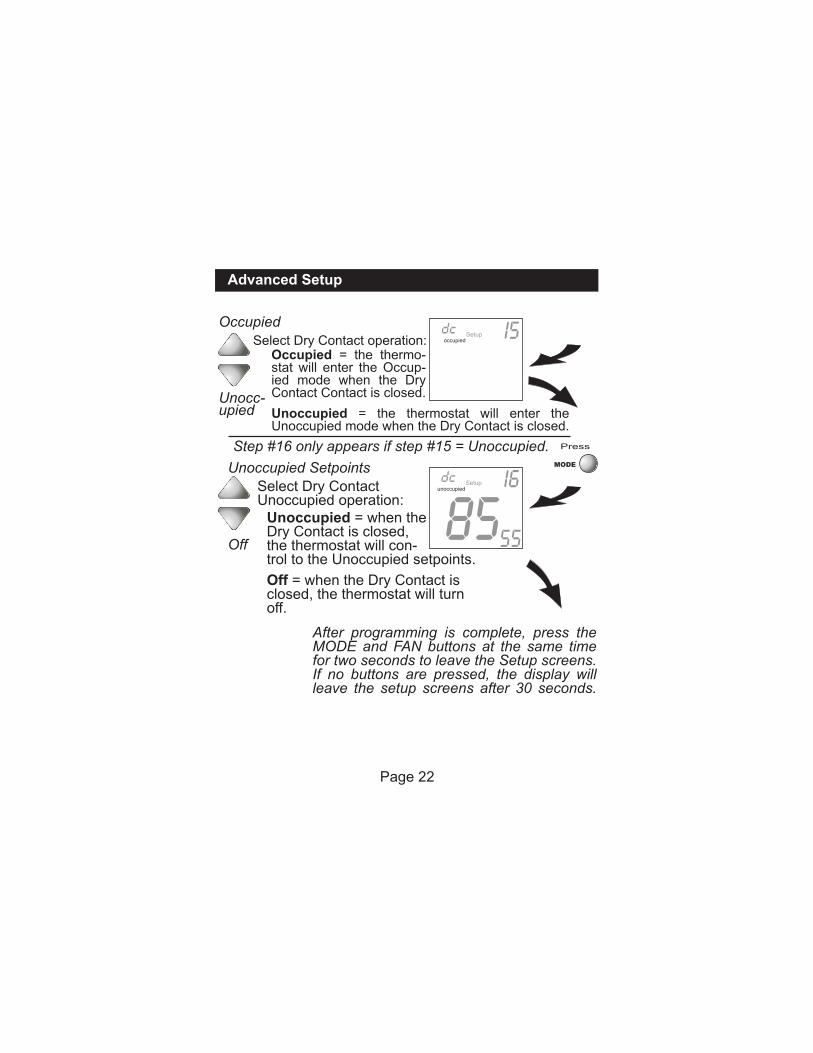
Select Dry Contact Unoccupied operation:
Unoccupied Setpoints
Off
Select Dry Contact operation:
Occupied
Unocc-upied
Setup I5
Step #16 only appears if step #15 = Unoccupied.
After programming is complete, press the MODE and FAN buttons at the same time for two seconds to leave the Setup screens. If no buttons are pressed, the display will leave the setup screens after 30 seconds.
occupied
Setup
85 I6
55
unoccupied
Press
MODE
Page 22
Unoccupied = the thermostat will enter the Unoccupied mode when the Dry Contact is closed.
Occupied = the thermo-stat will enter the Occup-ied mode when the Dry Contact Contact is closed.
Off = when the Dry Contact is closed, the thermostat will turnoff.
Unoccupied = when the Dry Contact is closed, the thermostat will con-trol to the Unoccupied setpoints.
Advanced Setup
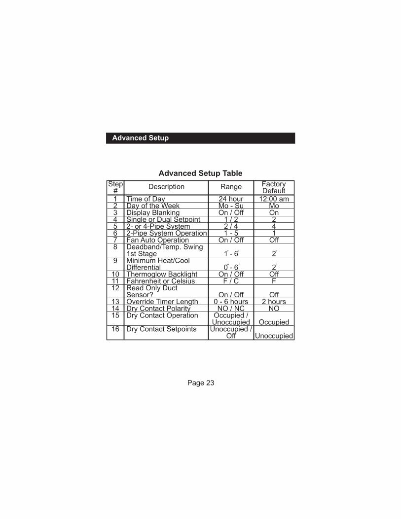
Range Factory Default
24 hourMo - SuOn / Off
1 / 22 / 41 - 5
On / Off
1 - 6
0 - 6On / Off
F / C
On / Off0 - 6 hoursNO / NC
Occupied / UnoccupiedUnoccupied /
Off
12:00 amMoOn241
Off
2
2OffF
Off2 hours
NO
Occupied
Unoccupied
Time of DayDay of the WeekDisplay BlankingSingle or Dual Setpoint2- or 4-Pipe System2-Pipe System OperationFan Auto OperationDeadband/Temp. Swing1st StageMinimum Heat/Cool DifferentialThermoglow BacklightFahrenheit or CelsiusRead Only Duct Sensor?Override Timer LengthDry Contact PolarityDry Contact Operation
Dry Contact Setpoints
Step#
Description
12345678
9
101112
131415
16
Advanced Setup Table
Page 23
About Advanced Features & Operation
Page 24
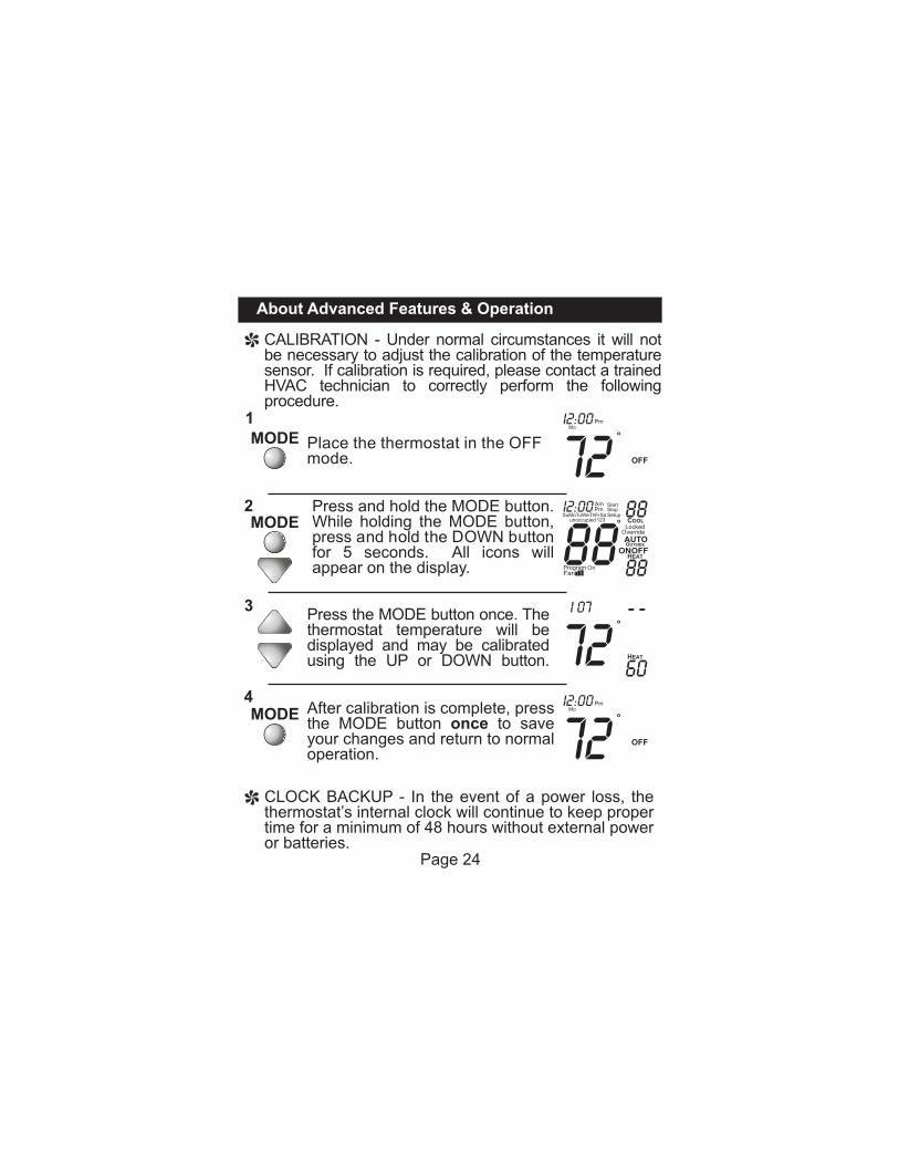
CLOCK BACKUP - In the event of a power loss, the thermostat’s internal clock will continue to keep proper time for a minimum of 48 hours without external power or batteries.
CALIBRATION - Under normal circumstances it will not be necessary to adjust the calibration of the temperature sensor. If calibration is required, please contact a trained HVAC technician to correctly perform the following procedure.
Place the thermostat in the OFF mode.
Press the MODE button once. The thermostat temperature will be displayed and may be calibrated using the UP or DOWN button.
After calibration is complete, press the MODE button once to save your changes and return to normal operation. 72
Pm
OFF
MoI2:00
Press button. While holding the MODE button, press and hold the DOWN button for 5 seconds. All icons will appear on the display.
and hold the MODE
72 60HEAT
i 07
Pm
OFF
MoI2:00
72
88unoccupied
AmPm
SuMoTuWeThFrSa123
I2:00 StopStart
Setup 88
88
COOL
HEAT
OverrideLocked
AUTOOUTSIDE
MODE1
2MODE
3
4MODE
About Advanced Features & Operation
Page 25
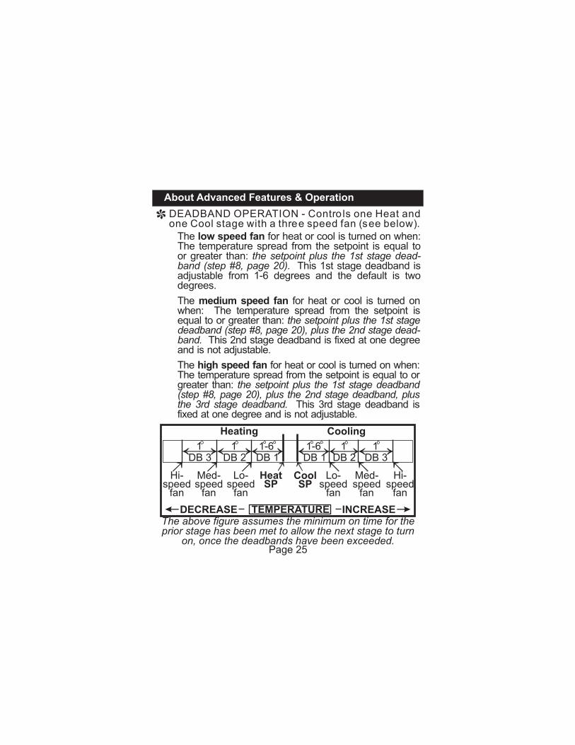
The above figure assumes the minimum on time for the prior stage has been met to allow the next stage to turn
on, once the deadbands have been exceeded.
TEMPERATUREDECREASE INCREASE
CoolSP
HeatSP
Med- speed
fan
Med-speed
fan
Heating Cooling
Lo-speed
fan
Hi- speed
fan
Lo-speed
fan
Hi-speed
fan
DEADBAND OPERATION - Contro ls one Heat and one Cool stage with a three speed fan (see below).
The medium speed fan for heat or cool is turned on when: The temperature spread from the setpoint is equal to or greater than: the setpoint plus the 1st stage deadband (step #8, page 20), plus the 2nd stage dead-band. This 2nd stage deadband is fixed at one degree and is not adjustable.
The low speed fan for heat or cool is turned on when: The temperature spread from the setpoint is equal to or greater than: the setpoint plus the 1st stage dead-band (step #8, page 20). This 1st stage deadband is adjustable from 1-6 degrees and the default is two degrees.
The high speed fan for heat or cool is turned on when: The temperature spread from the setpoint is equal to or greater than: the setpoint plus the 1st stage deadband (step #8, page 20), plus the 2nd stage deadband, plus the 3rd stage deadband. This 3rd stage deadband is fixed at one degree and is not adjustable.
DB 31
DB 21
DB 11-6
DB 11-6
DB 21
DB 31
About Advanced Features & Operation
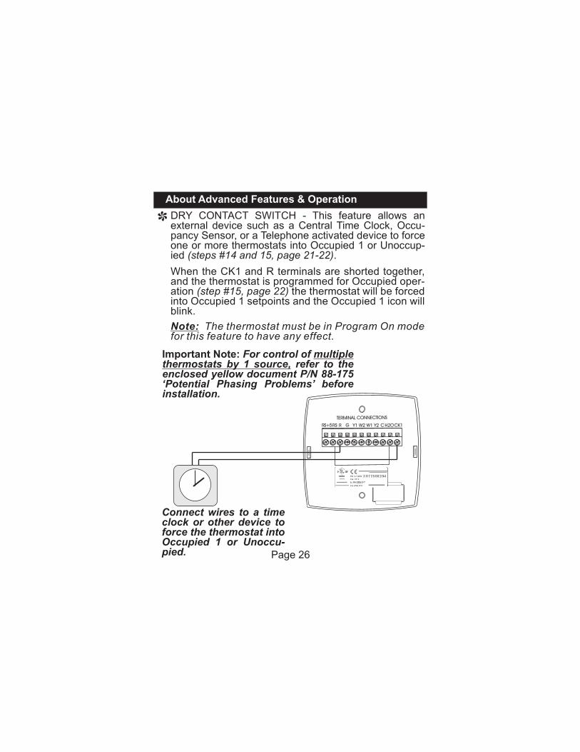
DRY CONTACT SWITCH - external device such as a Central Time Clock, Occu-pancy Sensor, or a Telephone activated device to force one or more thermostats into Occupied 1 or Unoccup-ied (steps #14 and 15, page 21-22).
This feature allows an
When the CK1 and R terminals are shorted together, and the thermostat is programmed for Occupied oper-ation (step #15, page 22) the thermostat will be forced into Occupied 1 setpoints and the Occupied 1 icon will blink.
Note: The thermostat must be in Program On mode for this feature to have any effect.
Connect wires to a time clock or other device to force the thermostat into Occupied 1 or Unoccu-pied.
Important Note: For control of multiplethermostats by 1 source, refer to the enclosed yellow document P/N 88-175 ‘Potential Phasing Problems’ before installation.
CGR Y1 W2 W1
TERMINAL CONNECTIONS
4Z95
24V. 60HZ
NEC CLASS 2
ENCLOSED
ENERGY
MANAGEMENT
EQUPIMENT
MODEL: E055-7150305
X072500204
MADE IN CHINA
Y2RSRS+5 H2OCK1
Page 26
About Advanced Features & Operation
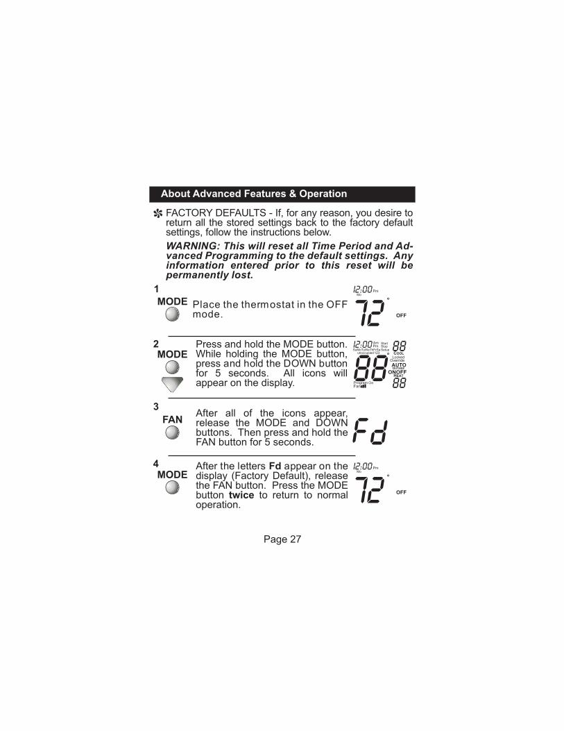
WARNING: This will reset all Time Period and Ad-vanced Programming to the default settings. Any information entered prior to this reset will be permanently lost.
FACTORY DEFAULTS - return all the stored settings back to the factory default settings, follow the instructions below.
If, for any reason, you desire to
After all of the icons appear, release the MODE and DOWN buttons. Then press and hold the FAN button for 5 seconds.
After the letters Fd appear on the display (Factory Default), release the FAN button. Press the MODE button twice to return to normal operation.
Page 27
Place the thermostat in the OFF mode.
72Pm
OFF
MoI2:00
Press button. While holding the MODE button, press and hold the DOWN button for 5 seconds. All icons will appear on the display.
and hold the MODE
Pm
OFF
MoI2:00
72
88unoccupied
AmPm
SuMoTuWeThFrSa123
I2:00 StopStart
Setup 88
88
COOL
HEAT
OverrideLocked
AUTOOUTSIDE
MODE1
2MODE
3
4MODE
FAN
About Advanced Features & Operation
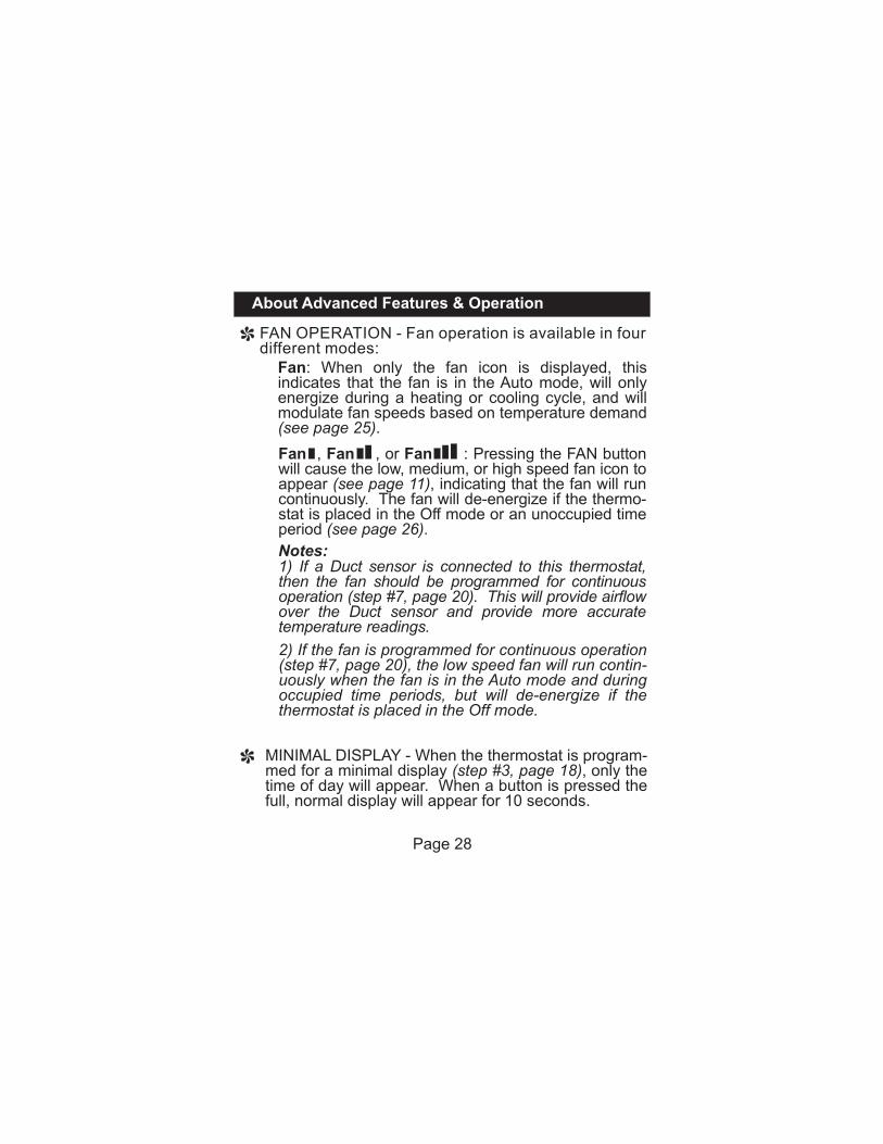
FAN OPERATION - Fan operation is available in four different modes:
Fan: When only the fan icon is displayed, this indicates that the fan is in the Auto mode, will only energize during a heating or cooling cycle, and will modulate fan speeds based on temperature demand (see page 25).
Page 28
Fan , Fan , or Fan : Pressing the FAN button will cause the low, medium, or high speed fan icon to appear (see page 11), indicating that the fan will run continuously. The fan will de-energize if the thermo-stat is placed in the Off mode or an unoccupied time period (see page 26).
1) If a Duct sensor is connected to this thermostat,then the fan should be programmed for continuous operation (step #7, page 20). This will provide airflow over the Duct sensor and provide more accurate temperature readings.
2) If the fan is programmed for continuous operation (step #7, page 20), the low speed fan will run contin-uously when the fan is in the Auto mode and during occupied time periods, but will de-energize if the thermostat is placed in the Off mode.
Notes:
MINIMAL DISPLAY - When the thermostat is program-med for a minimal display (step #3, page 18), only the time of day will appear. When a button is pressed the full, normal display will appear for 10 seconds.
About Advanced Features & Operation
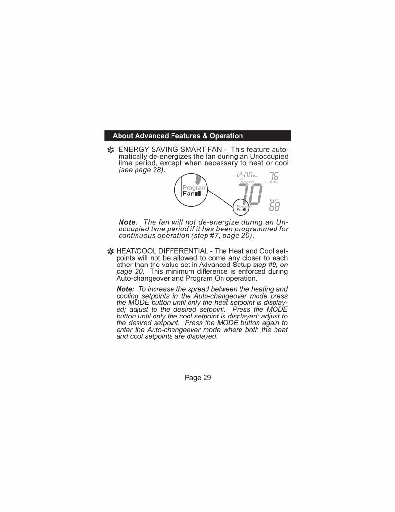
HEAT/COOL DIFFERENTIAL - The Heat and Cool set-points will not be allowed to come any closer to each other than the value set in Advanced Setup step #9, on page 20. This minimum difference is enforced during Auto-changeover and Program On operation.
ENERGY SAVING SMART FAN - matically de-energizes the fan during an Unoccupied time period, except when necessary to heat or cool (see page 28).
This feature auto-
70unoccupied
PmMo
I2:00 76
68
COOL
HEAT
Note: The fan will not de-energize during an Un-occupied time period if it has been programmed for continuous operation (step #7, page 20).
Page 29
Note: To increase the spread between the heating and cooling setpoints in the Auto-changeover mode press the MODE button until only the heat setpoint is display-ed; adjust to the desired setpoint. Press the MODE button until only the cool setpoint is displayed; adjust to the desired setpoint. Press the MODE button again to enter the Auto-changeover mode where both the heat and cool setpoints are displayed.
About Advanced Features & Operation
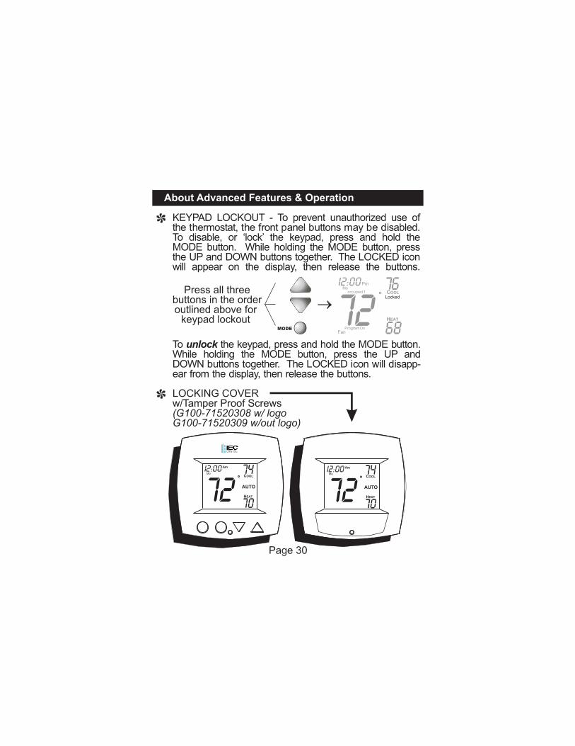
KEYPAD LOCKOUT - To prevent unauthorized use of the thermostat, the front panel buttons may be disabled. To disable, or ‘lock’ the keypad, press and hold the MODE button. While holding the MODE button, press the UP and DOWN buttons together. The LOCKED icon will appear on the display, then release the buttons.
To unlock the keypad, press and hold the MODE button. While holding the MODE button, press the UP and DOWN buttons together. The LOCKED icon will disapp-ear from the display, then release the buttons.
Press all three buttons in the order outlined above for
keypad lockoutMODE
7276
68
occupied
ProgramFan
On
Pm
COOL
HEAT
Locked
Mo1
I2:00
Page 30
LOCKING COVER w/Tamper Proof Screws (G100-71520308 w/ logo G100-71520309 w/out logo)
72 7274 74
70 70
Am Am
COOL COOL
HEAT HEAT
AUTO AUTO
Mo MoI2:00 I2:00
About Advanced Features & Operation
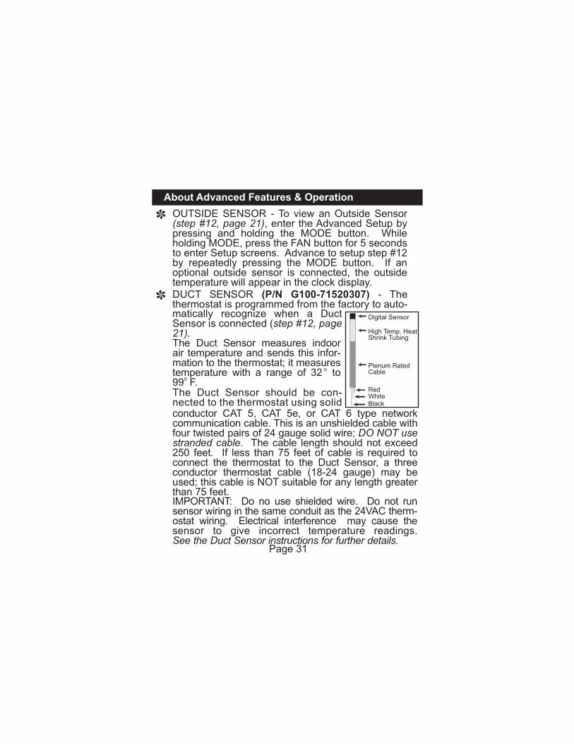
OUTSIDE SENSOR - To view an Outside Sensor (step #12, page 21), enter the Advanced Setup by pressing and holding the MODE button. While holding MODE, press the FAN button for 5 seconds to enter Setup screens. Advance to setup step #12 by repeatedly pressing the MODE button. If an optional outside sensor is connected, the outside temperature will appear in the clock display. DUCT SENSOR (P/N G100-71520307) - The thermostat is programmed from the factory to auto-
Page 31
matically recognize when a Duct Sensor is connected (step #12, page 21).The Duct Sensor measures indoor air temperature and sends this infor-mation to the thermostat; it measures temperature with a range of 32 to 99 F.The Duct Sensor should be con-nected to the thermostat using solid conductor CAT 5, CAT 5e, or CAT 6 type network communication cable. This is an unshielded cable with four twisted pairs of 24 gauge solid wire; DO NOT use stranded cable. The cable length should not exceed 250 feet. If less than 75 feet of cable is required to connect the thermostat to the Duct Sensor, a three conductor thermostat cable (18-24 gauge) may be used; this cable is NOT suitable for any length greater than 75 feet. IMPORTANT: Do no use shielded wire. Do not run sensor wiring in the same conduit as the 24VAC therm-ostat wiring. Electrical interference may cause the sensor to give incorrect temperature readings.See the Duct Sensor instructions for further details.
Digital Sensor
High Temp. HeatShrink Tubing
Plenum RatedCable
RedWhiteBlack
About Advanced Features & Operation
SINGLE SETPOINT BEHAVIOR - When configured for Single Setpoint operation (step #4, page 19), the degree icon will blink when the large number is display-ing room temperature and will remain solid when dis-playing the heating or cooling setpoint. In the Auto and Program On modes the deadband is enforced both above and below the setpoint. To avoid short cycling, a deadband of at least two degrees is recommended (step #8, page 20). To display the room temperature press and hold the MODE button for two seconds. Release the MODE button to return to the normal display.
Page 32
Warranty
Page 33
INTERNATIONAL ENVIRONMENTAL CORPORATION - TERMS AND CONDITIONS
1. ORDER ACKNOWLEDGEMENTS SHALL ONLY BE BINDING UPON INTERNATIONAL ENVIRONMENTAL CORPORATION (HEREINAFTER REFERRED TO AS IEC) IF GENERATED AND AUTHORIZED BY A REPRESENTATIVE OF IEC AT ITS OFFICE IN OKLAHOMA CITY, OKLAHOMA.
2. IEC DOES NOT BUILD ITEMS TO PLANS AND SPECIFICATIONS. IEC AGREES TO FURNISH ONLY THE ITEMS AS DESCRIBED IN IEC'S ORDER ACKNOWLEDGEMENT UNLESS IEC'S OFFICE IN OKLAHOMA CITY, OKLAHOMA, HAS PREVIOUSLY RECEIVED AND ACCEPTED, IN WRITING, APPROVED SUBMITTALS FROM PURCHASER.
3. PRICES QUOTED ARE FIRM ONLY IF PURCHASER RELEASES THE GOODS COVERED BY THIS ORDER FOR IMMEDIATE PRODUCTION BY IEC WITHIN NINETY (90) DAYS FROM THE DATE OF PURCHASER'S OFFER TO PURCHASE AND FOR SHIPMENT BY IEC WITHIN THE ACKNOWLEDGED SHIPPING DATE WHICH SHALL NOT EXCEED SIX (6) MONTHS FROM THE DATE OF PURCHASER'S OFFER TO PURCHASE. IF PURCHASER DOES NOT MEET THE TERMS AND CONDITIONS OF THIS PARAGRAPH, THE PRICES ARE SUBJECT TO ESCALATION TO THOSE PRICES IN EFFECT AT TIME OF SHIPMENT WITHOUT NOTICE TO PURCHASER.
4. ALL PRICES ARE F.O.B. IEC'S FACTORY WITH FULL FREIGHT ALLOWED UNLESS NOTED OTHERWISE BY IEC. TITLE TO AND RISK OF LOSS TO THE GOODS PASSES TO THE PURCHASER WHEN DELIVERED TO THE CARRIER F.O.B. IEC'S SHIPPING POINT. PURCHASER MUST INSPECT THE GOODS UPON ARRIVAL.
5. IF GOODS ARE RELEASED FOR PRODUCTION BUT IEC IS PREVENTED BY THE PURCHASER FROM SHIPPING UPON COMPLETION OR BY THE ACKNOWLEDGED SHIPPING DATE, WHICHEVER IS LATER, IEC MAY AT IT'S OPTION, IN ADDITION TO ALL OTHER REMEDIES, INVOICE THE PURCHASER TO BE PAYABLE WITHIN THIRTY (30) DAYS AND STORE THE GOODS AT PURCHASER'S SOLE EXPENSE.
6. TITLE TO AND RISK OF LOSS TO THE GOODS PASSES TO THE PURCHASER F.O.B. IEC'S SHIPPING POINT.
Warranty
Page 34
7. (a.) IEC WARRANTS FOR A PERIOD OF EIGHTEEN (18) MONTHS FROM THE DATE OF SHIPMENT OR TWELVE (12) MONTHS FROM DATE OF START UP (WHICHEVER OCCURS FIRST), THAT THE GOODS SOLD SHALL BE FREE OF DEFECTS IN MATERIAL AND WORKMANSHIP, EXCEPT THAT IEC MAKES NO GUARANTEE AGAINST CORROSION OR ABRASION OF ANY GOODS AND MAKES NO GUARANTEE WHATSOEVER FOR DAMAGES IN ANY WAY RELATING TO MOLD, FUNGUS OR BACTERIA, OR ANY GOODS MANUFACTURED OR SUPPLIED BY OTHERS. IEC MAKES NO OTHER EXPRESS WARRANTY, AND NO AFFIRMATION BY IEC OR ITS REPRESENTATIVES, BY WORD OR ACTION, SHALL CONSTITUTE A WARRANTY.(b.) IEC MAKES NO IMPLIED WARRANTIES OF MERCHANTABILITY OR
FITNESS FOR ANY PARTICULAR PURPOSE.(c.) IN THE EVENT OF A BREACH OF THE ABOVE WARRANTY OR NEGLIGENCE ON THE PART OF IEC, IEC SHALL ONLY BE OBLIGATED TO EITHER REPAIR OR REPLACE, AT IEC'S OPTION, THE GOODS, AND THE AFORESAID OBLIGATION OF IEC TO REPAIR OR REPLACE THE GOODS IS THE PURCHASER'S EXCLUSIVE REMEDY. IEC SHALL NOT, IN ANY MANNER WHATSOEVER, BE LIABLE FOR ANY INCIDENTAL OR CONSEQUENTIAL DAMAGES, LOSS OF PROFITS OR EXPENSES FOR BREACH OF WARRANTY, OR FOR NEGLIGENCE ON THE PART OF IEC.(d.) ALL PARTS SHALL BE RETURNED TO IEC'S FACTORY IN OKLAHOMA CITY, OKLAHOMA, OR OTHER AUTHORIZED SERVICE STATION DESIGNATED BY IEC, FREIGHT PREPAID IF IEC DETERMINES THE PART TO BE DEFECTIVE AND WITHIN IEC'S WARRANTY. IEC SHALL, WHEN SUCH PART HAS BEEN EITHER REPLACED OR REPAIRED, RETURN TO PURCHASER, F.O.B. IEC'S FACTORY IN OKLAHOMA CITY, OK.(e.) THIS WARRANTY SHALL BE VOID FOR ANY GOODS WHICH (1) HAVE BEEN REPAIRED OR ALTERED OUTSIDE IEC'S FACTORY IN ANY MANNER WITHOUT IEC'S WRITTEN AUTHORIZATION; OR (2) HAVE BEEN SUBJECT TO MISUSE, NEGLIGENCE OR ACCIDENTS; OR (3) HAVE BEEN OPERATED IN A MANNER CONTRARY TO IEC'S PRINTED INSTRUCTIONS: OR (4) HAVE NOT BEEN PAID FOR WITHIN PAYMENT TERMS GRANTED BY IEC.
8. IEC SHALL HAVE NO SYSTEM DESIGN, APPLICATION OR MAINTENANCE RESPONSIBILITY OR RESPONSIBILITY FOR MOLD, FUNGUS OR BACTERIA TO PURCHASER OR ANY OTHER THIRD PARTY.
Warranty
Page 35
9. ALL SALES, USE, EXCISE, TRANSPORTATION, PRIVILEGE, OCCUPATIONAL CONSUMPTION, STORAGE, OR OTHER TAXES WHICH MAY BE LEVIED BY ANY TAXING AUTHORITY AS A RESULT OF THIS TRANSACTION SHALL BE PAID BY THE PURCHASER.
10. UNLESS OTHERWISE AGREED TO IN WRITING BY IEC, ANY TECHNICAL DATA, FURNISHED IN CONJUNCTION WITH THIS ORDER AND NOT OBTAINABLE FROM ANOTHER SOURCE SHALL NOT BE DUPLICATED, USED, OR DISCLOSED IN WHOLE OR IN PART FOR ANY PURPOSE OTHER THAN TO EVALUATE THIS ORDER.
11. IEC SHALL HAVE NO LIABILITY OR OTHER OBLIGATION HEREUNDER, IF ITS PERFORMANCE IS DELAYED OR PREVENTED TO ANY EXTENT BY ANY EVENT SUCH AS, BUT NOT LIMITED TO, ANY ACT OF GOD, STRIKE OR WORK STOPPAGE, FIRE, FLOOD, ACCIDENT, ALLOCATION, OR OTHER CONTROLS OF GOVERNMENT AUTHORITIES, SHORTAGE OF TRANSPORTATION, FUEL, MATERIAL AND LABOR, OR ANY OTHER CAUSE BEYOND IEC'S REASONABLE CONTROL. ANY SHIPPING DATE STATED BY IEC IS IEC'S BEST ESTIMATE, BUT IEC MAKES NO GUARANTEE OF SHIPMENT BY ANY SUCH DATE AND SHALL HAVE NO LIABILITY OR OTHER OBLIGATION FOR FAILURE TO SHIP ON SUCH DATE, REGARDLESS OF CAUSE.
12. PAYMENT TERMS ARE NET THIRTY (30) DAYS FROM DATE OF INVOICE ON APPROVED CREDIT. ONE AND ONE-HALF PERCENT (1 1/2%) PER MONTH (18% ANNUAL RATE) MAY BE CHARGED ON PAST DUE ACCOUNTS WHERE PERMITTED BY APPLICABLE LAW. IN THE EVENT ACCOUNT MUST BE PLACED FOR COLLECTION, PURCHASER SHALL BE RESPONSIBLE FOR ALL REASONABLE ATTORNEYS FEES AND COSTS INCURRED BY IEC IN SECURING PAYMENT.
13. PURCHASER SHALL NOT CANCEL THE CONTRACT WITHOUT PRIOR WRITTEN CONSENT OF IEC. IN THE EVENT PURCHASER CANCELS THE CONTRACT WITH THE PRIOR WRITTEN CONSENT OF IEC AFTER THE PURCHASER'S OFFER TO PURCHASE IS RECEIVED AND ACKNOWLEDGED IN WRITING, IEC SHALL BE ENTITLED TO RECEIVE FROM PURCHASER, IEC'S COST PLUS A REASONABLE ALLOWANCE FOR OVERHEAD AND PROFIT.
14. PURCHASER SHALL NOT ASSIGN ANY OF ITS INTEREST RIGHTS UNDER THIS AGREEMENT WITHOUT WRITTEN CONSENT OF IEC.
15. IEC WILL NOT FURNISH LIEN WAIVERS OR RELEASES UNTIL IEC RECEIVES PAYMENT, IN FULL, AT ITS OFFICE IN OKLAHOMA CITY, OKLAHOMA, FROM PURCHASER FOR THE GOODS COVERED BY THIS ORDER. PARTIAL LIEN RELEASES WILL BE PROVIDED IF REQUESTED.
Warranty
16. ALL ORDERS ARE EXPRESSLY LIMITED AND MADE CONDITIONAL UPON ACCEPTANCE BY PURCHASER OF THE TERMS AND CONDITIONS LISTED ABOVE WITHOUT CHANGE. THERE SHALL BE NO UNDERSTANDINGS, AGREEMENTS, OR OBLIGATIONS (OUTSIDE THESE TERMS AND CONDITIONS) UNLESS SPECIFICALLY SET FORTH IN WRITING, AND ACCEPTED BY SIGNATURE OF AN AUTHORIZED REPRESENTATIVE OF IEC IN OKLAHOMA CITY, OKLAHOMA.
P/N 88-569Rev. 2
P.O. Box 2598 • Oklahoma City, OK 73101-2598 405.605.5000 [phone] 405.605.5001 [fax] www.iec-okc.com • • •
©2007 International Environmental Corporation (IEC). IEC is a subsidiary of LSB Industries, Inc. - AMEX symbol LXU; www.lsb-okc.com
I100-90006968