Embed Size (px)
Citation preview

V. 1.1 Fast & Fluid Management B. V.PO Box 220
2170 AE SassenheimThe Netherlands
www.fast-fluid.com
ManualHarbil HA450 / Harbil HA650
2
© Fast & Fluid Management B.V.This manual or parts thereof may not be reproduced, stored in a retrieval system, or transmitted, in any form or by any means, electronic, mechanical, photocopying, recording, nor otherwise, without the prior written permission of Fast & Fluid Management B.V.This manual could contain technical inaccuracies or typographical errors.Fast & Fluid Management B.V. reserves the right to revise this manual from time to time in the contents thereof without the obligation of Fast & Fluid Management B.V. to notify any person of such revision or change.Details and values given in this manual are average values and have been compiled with care. They are not binding, however, and Fast & Fluid Management B.V. disclaims any liability for damage or detriments suffered as a result of reliance on the information given herein or the use of products, processes or equipment to which this manual refers. No warranty is made that the use of the information or of the products, processes or equipment to which this manual refers will not infringe any third party’s patents or rights. The information given does not release the user from making their own experiments and tests.

3
Table of Contents HA450 / HA650 V. 1.1
Table of Contents
1 About this manual......................................................................................................... 51.1 How to work with the manual............................................................................................ 51.2 Record of changes ........................................................................................................... 5
2 Safety ............................................................................................................................. 72.1 Intended use..................................................................................................................... 72.2 Liability.............................................................................................................................. 7
2.2.1 General liability ..................................................................................................... 72.2.2 Machine-specific liability ....................................................................................... 7
2.3 User qualification for installation....................................................................................... 82.4 CE certification ................................................................................................................. 82.5 Safety symbols on the machine........................................................................................ 82.6 Safety symbols in the manual........................................................................................... 92.7 Disposal of the machine ................................................................................................... 9
3 Operator manual ......................................................................................................... 113.1 Description...................................................................................................................... 11
3.1.1 Overview of the machine.................................................................................... 113.1.2 Overview of the controls..................................................................................... 123.1.3 Overview of the machine (back)......................................................................... 133.1.4 Type plate: serial number................................................................................... 143.1.5 Type plate: details .............................................................................................. 14
3.2 Operation........................................................................................................................ 153.2.1 General dispensing procedure ........................................................................... 153.2.2 Place the can...................................................................................................... 153.2.3 Move up the can table ........................................................................................ 163.2.4 Move down the can table ................................................................................... 16
3.3 Maintenance................................................................................................................... 163.3.1 General cleaning: after every dispensing operation ........................................... 163.3.2 Cleaning of the brush container: daily ................................................................ 163.3.3 Cleaning of the switch plate: monthly................................................................. 183.3.4 Refilling of a canister .......................................................................................... 203.3.5 Using the emergency stop switch....................................................................... 21

4
Table of Contents HA450 / HA650 V. 1.1
4 Installation ................................................................................................................... 234.1 Unpack the machine....................................................................................................... 23
4.1.1 Remove the cardboard....................................................................................... 234.1.2 Remove the transport brackets at the front ........................................................ 234.1.3 Remove the transport brackets at the rear......................................................... 244.1.4 Remove the wooden beams............................................................................... 244.1.5 Remove the plastic protection on the canisters.................................................. 244.1.6 Remove the plastic protection from the switchplate ........................................... 25
4.2 Put the machine in position ............................................................................................ 254.2.1 Move the machine to the final location, with a ramp (optional) .......................... 254.2.2 Put the machine on the final location ................................................................. 254.2.3 Place the step..................................................................................................... 264.2.4 Turn the step ...................................................................................................... 26
4.3 Install the computer ........................................................................................................ 264.3.1 Open the back cover .......................................................................................... 264.3.2 Install the computer ............................................................................................ 27
4.4 Turning on the machine.................................................................................................. 274.5 First use.......................................................................................................................... 27
5 Troubleshooting.......................................................................................................... 295.1 Contact service............................................................................................................... 295.2 Audio signals .................................................................................................................. 295.3 Error messages and other faults .................................................................................... 30
6 Technical data ............................................................................................................. 316.1 General specifications .................................................................................................... 316.2 Dimensions and mass .................................................................................................... 316.3 Ambient conditions ......................................................................................................... 326.4 Noise level ...................................................................................................................... 326.5 Safety classifications ...................................................................................................... 326.6 Electrical specifications .................................................................................................. 326.7 Pump specifications........................................................................................................ 336.8 Electrical diagram........................................................................................................... 34

5
About this manual HA450 / HA650 V. 1.1
1 About this manual
The manual shows the information necessary to:- install- operate- perform basic maintenance- correct small problems.
The HA450, the HA650 and all their versions are referred to in the manual as the ’machine’.
This manual contains the original instructions. The original language of the manual is English. All other language versions are translations of the original instructions.
1.1 How to work with the manual
For the safe use of the machine, it is important that you:1 Familiarize yourself with the structure and content.2 Read the safety chapter in detail and make sure you understand all the instructions. See § 2.3 Carry out the actions completely and in the given sequence.
1.2 Record of changes/i
Edition Editor Check Date Description
1.0 ES TB 10/2013 First edition
1.1 EvT TB 11/2014 Additional procedure and updates

6
About this manual HA450 / HA650 V. 1.1

7
Safety HA450 / HA650 V. 1.1
2 Safety
2.1 Intended use
The machine is designed to dispense colorants into a can. Any other use of the machine is strictly forbidden.
2.2 Liability
2.2.1 General liability
Our machines and accessories are fully compliant with the CE regulations. Any modification can result in not fulfilling the CE safety requirements and is therefore not allowed. Fast & Fluid Management B.V. will not accept any responsibility in case of modifications to machines and/or accessories.
Fast & Fluid Management B.V. is not liable if you do not follow the rules below:- The machine is for indoors use only.- This machine may only be used for commercial settings. The machine is not a household appliance.- Observe all local safety regulations.- Mind the minimal requirement of the building structure of the load capacity of the floor.- Place machine in a well-lit and well ventilated room.- Install and connect the machine according to the instructions in this manual.- Connect the machine to a grounded wall socket.- Do not use extension cords.- Do not place objects on top of the machine.- Do not use a damaged machine. When you have doubts, contact your supplier. See § 5.1.- Keep the machine in good condition. Make sure that defective parts are immediately replaced.- Replace parts only with original Fast & Fluid Management B.V. spare parts.
All maintenance beyond the scope of this manual must be carried out by a qualified service technician that Fast & Fluid Management B.V. has trained and certified.
2.2.2 Machine-specific liability
This machine is designed to dispense colorants into a can in non-hazardous conditions.
Please consult the health & safety officer of your paint supplier and/or colorant supplier on how to avoid the emergence of hazardous situations like personal harm or the risk for fire and explosion.
- Personal harm should be avoided by strictly following the materials safety data sheets (MSDS) for colorants, (base) paint and brush liquid.
- Do not use flammable liquids in the brush container.- The use of flammable colorants or colorants that diffuse potential explosive vapors may present fire and
explosion risks.
WARNINGRead the manual before you install or use the machine. Failure to do so can result in personal injury, death or property damage.

8
Safety HA450 / HA650 V. 1.1
2.3 User qualification for installation
Only install the machine if you have written permission from the supplier of the machine.
2.4 CE certification
The machine is CE certified. This means that the machine complies with the essential requirements concerning safety. The directives that have been taken into consideration in the design are available on www.fast-fluid.com.
2.5 Safety symbols on the machine/i
Rotating parts hazard Pinch hazard for your hand
Central earthing point Pinch hazard for your foot
Read the manual Caution
Electrical hazard Can table switch up/down
Instruction On/off

Safety HA450 / HA650 V. 1.1
9
2.6 Safety symbols in the manual/i
2.7 Disposal of the machine
1. Sort the machine, the accessories and the packaging for environmentally friendly recycling.
2. Do not dispose of the machine into domestic waste. Dispose of the machine according to local regulations.
3. Dispose of the canisters as chemical waste, according to the local regulations.
WARNINGCan cause personal injury.
WARNINGPinch hazard for your foot.
CAUTIONCan cause damage to the machine.
NoteShows further information.
10
Safety HA450 / HA650 V. 1.1
11
Operator manual HA450 / HA650 V. 1.1
3 Operator manual
3.1 Description
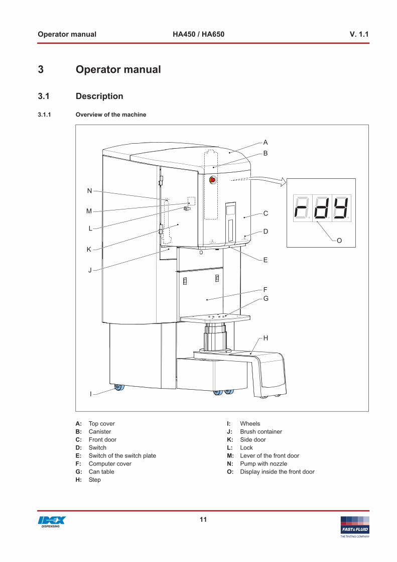
3.1.1 Overview of the machine
A: Top cover B: CanisterC: Front doorD: SwitchE: Switch of the switch plateF: Computer coverG: Can tableH: Step
I: WheelsJ: Brush containerK: Side doorL: LockM: Lever of the front doorN: Pump with nozzleO: Display inside the front door
B
C
D
A
F
E
O
G
H
J
I
K
M
N
L

12
Operator manual HA450 / HA650 V. 1.1
3.1.2 Overview of the controls
A: Emergency stop switchB: Can table switchC: Computer switch
B
C
A

13
Operator manual HA450 / HA650 V. 1.1
3.1.3 Overview of the machine (back)
A: LockB: Back coverC: Type plateD: Net entryE: 5-Way socket
DC
B
A
E

14
Operator manual HA450 / HA650 V. 1.1
3.1.4 Type plate: serial number
3.1.5 Type plate: details
Model
XXXXX-XX (Xxxxxxx)Prod. Week XX-XXXX
Serial No:
XXXXXXXXX-XXXXXX
THE TINTING COMPANY www.fast-fluid.com
Fast & Fluid Management B.V.IDEX Dispensing P.O. Box 2202170 AE SassenheimThe Netherlands
THE TINTING COMPANY www.fast-fluid.com
XXX V~ XX/XX Hz XXX WModel XXX XX-XXXSerial no. XXXXXXXXX-XXXXXXProd.week XX-XXXXMass XXXkgFuse X AT
Patented familiesXXxxxxxxxXXxxxxxxxXXxxxxxxx
Design
Fast & Fluid Management B.V.IDEX Dispensing P.O. Box 2202170 AE SassenheimThe Netherlands
Made in Xxxxxx
Operator manual HA450 / HA650 V. 1.1
15
3.2 Operation
3.2.1 General dispensing procedure
For all the software instructions: see the software documentation.
1. Place the can. See § 3.2.2.2. Move the can table up. See § 3.2.3.3. Choose the recipe and dispense. See the software
documentation.4. Move the can table down. See § 3.2.4.5. Remove the can.
3.2.2 Place the can
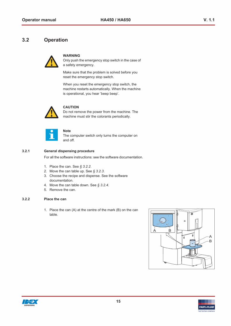
1. Place the can (A) at the centre of the mark (B) on the can table.
WARNINGOnly push the emergency stop switch in the case of a safety emergency.
Make sure that the problem is solved before you reset the emergency stop switch.
When you reset the emergency stop switch, the machine restarts automatically. When the machine is operational, you hear ’beep beep’.
CAUTIONDo not remove the power from the machine. The machine must stir the colorants periodically.
NoteThe computer switch only turns the computer on and off.
A B
AB
Operator manual HA450 / HA650 V. 1.1
16
3.2.3 Move up the can table
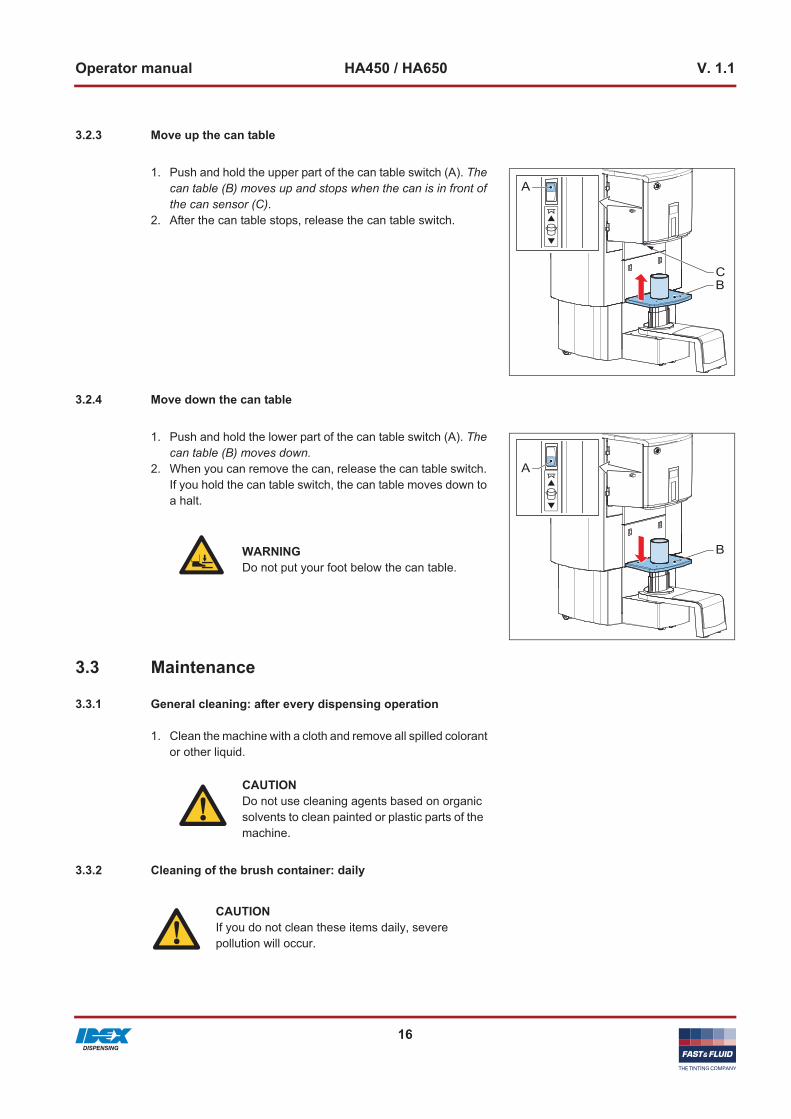
1. Push and hold the upper part of the can table switch (A). The can table (B) moves up and stops when the can is in front of the can sensor (C).
2. After the can table stops, release the can table switch.
3.2.4 Move down the can table
1. Push and hold the lower part of the can table switch (A). The can table (B) moves down.
2. When you can remove the can, release the can table switch. If you hold the can table switch, the can table moves down to a halt.
3.3 Maintenance
3.3.1 General cleaning: after every dispensing operation
1. Clean the machine with a cloth and remove all spilled colorant or other liquid.
3.3.2 Cleaning of the brush container: daily
A
CB
A
BWARNINGDo not put your foot below the can table.
CAUTIONDo not use cleaning agents based on organic solvents to clean painted or plastic parts of the machine.
CAUTIONIf you do not clean these items daily, severe pollution will occur.
Operator manual HA450 / HA650 V. 1.1
17
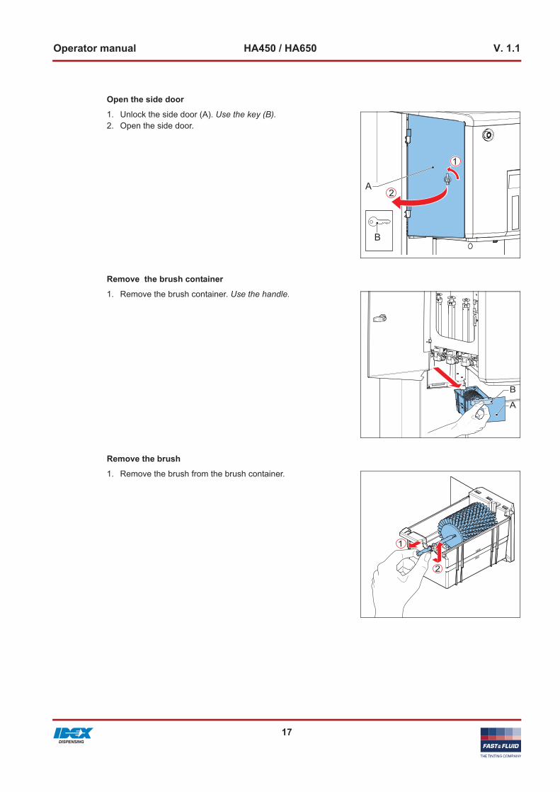
Open the side door
1. Unlock the side door (A). Use the key (B).2. Open the side door.
Remove the brush container
1. Remove the brush container. Use the handle.
Remove the brush
1. Remove the brush from the brush container.
A
B
B
A

Operator manual HA450 / HA650 V. 1.1
18
Clean the brush container
1. Remove the liquid from the brush container. For the disposal of the liquid, follow the local regulations.
Fill the brush container
1. Fill the brush container with the liquid that your paint supplier indicates. The level of the liquid must be between the “MIN” and “MAX” mark.
Put back the brush container
1. Put back the brush container.2. Close the side door.3. Lock the side door.
3.3.3 Cleaning of the switch plate: monthly
Open the covers1. Open the side door. See § 3.3.2.
WARNINGDo not put flammable liquids in the brush container.
B
A

Operator manual HA450 / HA650 V. 1.1
19
2. Open the top cover (A).
3. Unlock the front door (B). Push down the lever (A).4. Open the front door.
Remove the switch plate
1. Remove the switch plate (A).a. Lift the switch plate from the switch plate switches.b. Pull out the switch plate.
Clean the switch plate1. Clean the switch plate. Use a cleaning cloth with a non-
organic cleaning liquid.
A
B
A
A

Operator manual HA450 / HA650 V. 1.1
20
Put back the switch plate
1. Put back the switch plate (A).a. Slide in the switch plate.b. Move down the switch plate until it makes contact with the
switch plate switches. The switch plate is deactivated.
Examine the switches of the switch plate
1. Make sure that the switch plate makes good contact with the switches of the switch plate. Otherwise the switch plate is activated.
3.3.4 Refilling of a canister
A
WARNINGCheck the material safety data sheet (MSDS) of the colorants for the personal protection measures that are required for handling the colorant.
CAUTIONMake sure that the colorant level in the canister is correct. If a canister is empty, this can cause an inaccurate dispensing and/or a recipe fault.
NoteThe software checks the level of colorant in each canister. The software on the machine shows when you need to refill a canister.

Operator manual HA450 / HA650 V. 1.1
21
1. In the software, activate the fill canister option.2. Open the top cover (A).3. Remove the lid of the canister (B).4. Add the colorant (C). Do not spill.
3.3.5 Using the emergency stop switch
1. Push the emergency stop switch (A). The machine stops immediately.
2. Solve the problem as quickly as possible.
3. Reset the emergency stop switch by turning the emergency stop switch. The machine restarts automatically.
1
2
3
A
C
B
ACAUTIONOnly push the emergency stop switch in the case of a safety emergency. Do not use the emergency stop switch as an on/off function!
CAUTIONWhen the machine is shut down, the stirring mechanism, which is necessary to keep the colorant in optimal condition, is also shut down.
NoteAfter the reset, the machine is operational when you hear two 'beeps'.

Operator manual HA450 / HA650 V. 1.1
22

Installation HA450 / HA650 V. 1.1
23
4 Installation
4.1 Unpack the machine
4.1.1 Remove the cardboard
1. Remove the cardboard (A) and the plastic from the outside of the machine.
4.1.2 Remove the transport brackets at the front
1. Lift the cover (A).2. Unscrew the transport bracket (B) and remove it.
A
10mm
B
A

24
Installation HA450 / HA650 V. 1.1
4.1.3 Remove the transport brackets at the rear
1. Open the back cover (A). Use the key (B).2. Remove the back cover. Let the back cover move towards
you. Then lift the cover.3. Unscrew the transport brackets (C) and (D) and remove
them.
4.1.4 Remove the wooden beams
1. Remove the wooden beams.
4.1.5 Remove the plastic protection on the canisters
1. Remove the blue tape and open the top cover.2. Remove the plastic protection.
10mm
B
D
A
C

Installation HA450 / HA650 V. 1.1
25
4.1.6 Remove the plastic protection from the switchplate
1. Open the side door. See § 3.3.2.2. Remove the plastic protection from the switchplate.
4.2 Put the machine in position
4.2.1 Move the machine to the final location, with a ramp (optional)
1. Place the ramp (A).2. Move the machine from the pallet on to the ground.3. Move the machine to the final location.4. Connect the power cable to the net entry.
4.2.2 Put the machine on the final location
1. Slide down the side panel to hide the wheels.
A
CAUTIONDo not connect the power cable to the wall socket.
CAUTIONDo not remove the side panel to prevent damage.

26
Installation HA450 / HA650 V. 1.1
4.2.3 Place the step
1. Place the step from the left side under the can table.
4.2.4 Turn the step
1. Turn the step to the front.
4.3 Install the computer
4.3.1 Open the back cover
1. Open the back cover. See § 4.1.32. Remove the back cover.

27
Installation HA450 / HA650 V. 1.1
4.3.2 Install the computer
1. Put the computer in the machine.2. Connect the power cables of the computer and the screen to
the 5-way socket (A).3. Connect an USB cable between the computer and the power
board (B).4. Connect the keyboard, the mouse and the screen to the
computer.
4.4 Turning on the machine
1. Connect the power cable to the wall socket. When the machine is operational, you hear two ’beeps’.
2. Make sure that the emergency stop switch is reset. See § 3.3.5.
3. Set the computer switch to ‘ON’.
4.5 First use
1. Fill the brush container. See § 3.3.2.2. Fill the canisters correctly. See § 3.3.4.3. Purge the canister. Use the purge command in the software.
See the software documentation.4. Do step 3 again for all canisters.
NoteUsually, the computer already has the correct software and drivers installed. If not, see the instructions in the installation manuals of your software provider.
AB
NoteFirst the air will come out of the nozzle. When the output is continuous, the tube is filled.

28
Installation HA450 / HA650 V. 1.1

Troubleshooting HA450 / HA650 V. 1.1
29
5 Troubleshooting
5.1 Contact service
1. Find the type plate on the rear of the machine. See § 3.1.5.2. Take a note of the model number and the serial number of the
machine.3. Contact your supplier or manufacturer.
See www.fast-fluid.com.
5.2 Audio signals
NoteSee the column Possible solution to solve the problem. When the problem persists, contact service. See § 5.1.
Problem Possible cause Solution
••• − − − •••SOS signal during the stirring.
The agitation motor is malfunctioning, a cable is broken or the power board is malfunctioning.
Contact service. See § 5.1.
- - - - >1 long interrupted beep (continuously 1 sec. on, 1 sec off)
Stirring function cannot start because the top cover is open.
Close the top cover.
•••••5 short beeps
A valve timeout occurred. Restart the machine.
••2 short beeps
The machine initializes. -
−−−−− >1 long uninterrupted beep
The side door is open during the dispense.
Close the door.
The front door is open during the dispense.
Close the door.
The brush container is missing. Put back the brush container.
The switch plate is activated.Examine the switches of the switch plate. Deactivate the switch plate.See § 3.3.3.
The can makes contact with the switch plate.
Move down the can table.See § 3.2.4.
•1 short beep
The top cover is open when the machine starts to dispense, or when the can table moves.
Close the top cover.

30
Troubleshooting HA450 / HA650 V. 1.1
5.3 Error messages and other faults
NoteFor all error messages on the computer: see the help topic in the dispense software.
NoteSee the column Possible solution to solve the problem. When the problem persists, contact service. See § 5.1.
Problem Possible cause Possible solution
Main power supply is present but the machine does not work.
The emergency stop switch is active.
Reset the emergency stop switch. See § 3.3.5.
A fuse is broken. Contact service. See § 5.1.
Display shows E01 The machine is not initialized. Restart the machine.
Display shows E02
The side door is open. Close the door.
The front door is open. Close the door.
The brush container is missing. Put back the brush container.
Display shows E43The pump is blocked or a motor, cable, or sensor faillure occurred.
Restart the machine.
Display shows E44A pump (motor / cable) or sensor faillure occurred.
Restart the machine.
Display shows E49 The can is missing. Place the can.
Display shows E63 The switch plate is activated.Examine the switches of the switch plate. Deactivate the switch plate.See § 3.3.3.
Display shows E72 The top cover is open. Close the top cover.
All other E - errors - Restart the machine.

31
Technical data HA450 / HA650 V. 1.1
6 Technical data
6.1 General specifications/i
6.2 Dimensions and mass/i
Parameter Specification
HA450 HA650
Number of canisters (max.) 32 36
Dispensing Sequential
Pump type Harbil piston pump
Cleaning system Automatic
Materials used are suitable for Water-, universal- and solvent-based colorants
Canister sizes [L] 2, 3, 6, 10 2, 3, 6, 10, 20
Pump capacity [oz] 1, 2, 5, 10
Maximal can height [cm] for low, standard, and high model respectively
42, 46, 62
Can table dimensions [cm] 44 x 31
Parameter Specification
HA450 HA650
Dimensions, height x width x depth [cm]
151 / 171 x 88 x 96 151 / 171 x 115 x 125
Packed dimensions (height x width x depth) [cm]
193 x 117 x 98 192 x 148 x 126
Mass incl. packaging [kg] ± 290 ± 420
Mass filled machine [kg] 450 860
Required load capacity of the floor [kg]
1800 3440

32
Technical data HA450 / HA650 V. 1.1
6.3 Ambient conditions/i
6.4 Noise level/i
6.5 Safety classifications/i
6.6 Electrical specifications/i
Parameter Specification
Temperature [°C] +15 to +40
Transportation temperature empty canisters [°C] +25 to +55
Altitude above sea level [m], operational -10 to 2000
Altitude above sea level [m], out of operation -10 to 12000
Maximum relative humidity [RH], without condensation [%]
90
Parameter Specification
Maximum noise level [dB(A)] < 65
Parameter Specification
IP (Ingress Protection) classification 32
EMC (ElectroMagnetic Compliancy) classification Class B
Overvoltage classification Class II
Parameter Specification
Power consumption, maximum [W] 500
Maximum leakage current [mA] 3.5
Country specific net cables European
Voltage [V] 230 ± 10%
Frequency [Hz] 50 / 60
Fuse specifications [A] 10

33
Technical data HA450 / HA650 V. 1.1
6.7 Pump specifications/i
Parameter Specification
Pump capacity [oz] 1 2 5 10
Resolution [ml/step] 0.002 0.004 0.010 0.020
Maximum flow speed1 [L/min] 0.2 0.4 0.8-1 1.5-2
Mininimum dispense [ml] 0.05 0.08 0.15 0.30
Nozzle diameter Small-Large [mm] 2 & 4 2 & 4 2 & 4 6
1. Depending on the colorant
34
Technical data HA450 / HA650 V. 1.1
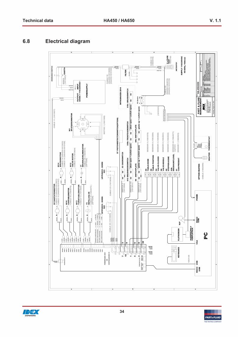
6.8 Electrical diagram5 5
4 4
3 3
2 2
1 1
DD
CC
BB
AA
HE
AT
ER
RS2
32
SLP
N
TH
ER
MO
ST
AT
OPT
ION
HEA
TIN
G
PC
POW
ER
FLA
TSC
RE
EN
US
B
PO
WER
SUPP
LY
+
-+
-
-
-+
-++
SE
NS
OR
1 (1
8640
23)
SW
ITC
H 9
(181
383
2)
MO
TO
R 1
(18
6198
8)
SW
ITC
H 3
(181
382
6)
SE
NS
OR
4 (1
8640
20)
SE
NS
OR
6 (1
8632
84)
SE
NS
OR
2 (1
8640
22)
CA
BLE
12
(181
3824
)
SE
NS
OR
8 (1
8640
21)
CA
BLE
11
(181
3827
)
CA
BLE
14
(HA
450:
1813
822)
CA
BLE
13
(181
3825
)
CA
BLE
16
(186
4070
)
SE
NS
OR
5 (1
8619
79)
(181
533
1)
VG
APO
WER
SUPP
LYFO
R FL
ATS
CR
.
CA
BLE
18
(HA
450:
181
3828
)(H
A65
0:1
8151
69)
CA
BLE
15
(HA
450:
1813
821)
BLUEBLACKBROWN
BLUEBLACKBROWN
1 28
4
65
93
CA
BLE
(186
2586
)
21
N
KEY
BO
AR
D
1863
146
50-6
0Hz,
10A
max
2 x
FUSE
10A
T
SUP
PLY
110
/230
VA
C
1602
782
CA
BLE
19
(186
401
8)
1 21
a.2a
LN
PE+
-
EA
RT
H
SW
ITC
H 1
0 (1
8138
31)
RS2
32
/USB
(doo
r op
en =
sw
itch
ope
n)
(doo
r op
en =
sw
itch
ope
n)
(pla
te u
p =
swit
ch o
pen
)
nono
nono
nono
nono
nono
CA
BLE
22
(181
3829
)C
AB
LE 2
3 (1
8138
30)
10
WIR
ES
(181
382
3)
CAB
LE 2
0(H
A45
0:1
8640
19)
(HA
650:
181
5170
)
110
/230
VA
C~
43V
DC
=IN
PUT
OU
TP
UT
SE
NS
OR
24
(186
4071
)(o
ptio
n)
24
+
+-
CA
BLE
26
(186
4072
)(O
PT
ION
)
-
CA
BLE
25
(186
407
2 )
(OP
TIO
N)
FILT
ER
CA
BLE
15
(HA
650:
1815
167)
CA
BLE
14
(HA
450:
1815
168)
7
/USB
nono
INTR
OD
UC
ED 2
014
(pla
te u
p =
swit
ch o
pen
)
Thur
sday
, Aug
ust
14, 2
014
1
HA
-450
/650
1.2
16-1
0-20
07N
vB
Add
ed b
rush
swit
ch o
ptio
n, d
oubl
e fu
sed
entr
y.
Firs
t ve
rsio
nA
dded
HA
650
cabl
esC
hang
ed c
entr
al e
arth
& w
cd p
artn
umbe
rA
dded
pis
tond
etec
tors
wit
ch o
ptio
nA
dded
new
ste
pper
mot
orw
irec
olor
sA
dded
Con
trol
Boa
rdV
4 / c
orre
cted
pos
itio
n.
HA
450.
DS
N
13-1
0-20
091.
510
-11-
2009
1.51
10-2
-201
41.
614
-8-2
014
1.7
NvB
NvB
NvB
NvB
NvB
NvB
27-1
-200
91.
36-
7-20
091.
4©
200
2 Fl
uid
Man
agem
ent
Hub
van
Doo
rnew
eg 3
1P.
O.B
ox 2
2021
70A
E S
AS
SE
NH
EIM
1.7
Rev
nr.
She
et
Tit
le
Dat
eD
raw
nR
emar
ks
File
nam
e
FAS
T &
FLU
IDM
AN
AG
EM
EN
TV
ersi
on
YEL
/GR
N
RED
& W
HIT
E/Y
ELLO
Wor
R
EDor
RED
OR
AN
GE
& W
HIT
E/B
LAC
Kor
B
LUE
or Y
ELLO
W
BR
OW
N
BR
OW
N
BR
OW
N
BR
OW
N
BLU
E
BR
OW
N
BLUE
BLU
E
WH
ITE
WH
ITE
BLA
CK
BLA
CK
YEL/GRN
BLU
E
BLU
E
BR
OW
N
BLU
E
BLU
E
BLA
CK
& W
HIT
E/O
RA
NG
Eor
O
RA
NG
Eor
GR
EEN
YEL
LOW
& W
HIT
E/R
EDor
Y
ELLO
Wor
WH
ITE
BR
OW
N
YEL/GRNYEL/GRNYEL/GRN
YEL
/GR
N
YEL/GRN
BLU
E
BROWN
BR
OW
N
BR
OW
N
BR
OW
N
BROWN
BR
OW
N
BROWN
BR
OW
N
BLU
E
BLUE
BR
OW
N
BLU
E
BR
OW
N
BLUE
BLU
E
BLU
E
BROWNB
RO
WN
BROWN
BROWN
BLU
E
BLU
E
BLUE
BLUE
BR
OW
N
BLU
E
BLUE
BROWN
BLUE
BROWN
BLUE
CA
NTA
BLE
MO
TOR
M1
6
S22
UP/P
UN
CH
- D
OW
N
S9SW
ITC
HPL
ATEVA
LVE
MO
TOR
M1
2
BR
US
HM
OT
OR
M1
4
S10
BR
USH
DO
OR
SWIT
CH
AG
ITA
TIO
NM
OTO
RM
15
TU
RN
TA
BL
EM
OT
OR
M1
3
MG
ND
3
HH
B7
HH
B14
HH
B13
MG
ND
3
HH
B12
HH
B11
HH
B10
HH
B9
HH
B8
MG
ND
2
MG
ND
2
HH
B6
MG
ND
2
MG
ND
1
HH
B5
HH
B4
HH
B3
HH
B2
HH
B1
CO
MM
UN
ICA
TIO
N
PB20
01:R
S23
2
POW
ER
SU
PPLY
-
+
-S
+S
+-
POW
ERB
OA
RD
200
1
CO
NTR
OLB
OA
RD
V4
OR
CB
V4:
U
SB
RS
232
RS
232
S7PIS
TO
ND
ETEC
TOR
SWIT
CH
(OPT
ION
)
S1 CA
N-P
RES
ENT
S2 STEP
PER
-HO
ME
S4 VA
LVE-C
LOS
ED
S5 TAB
LE-H
OM
E
S6 TA
BLE
PO
SITI
ON
S24
.B
RU
SHU
NIT
LEV
EL
S3D
OO
RSW
ITC
H
S9b
SW
ITC
HPL
ATE
S10
bFR
ON
TDO
OR
SWIT
CH
I O
PC
-Sw
itch
L1 BR
USH
LEV
ELIN
DIC
ATO
R
S10
cB
RU
SHSW
ITC
H
NETEN
TR
Y
S23
UP/P
UN
CH
- D
OW
N
S8 VAL
VE-M
IDD
LE
Y1
REFI
LLV
AL
VE
1
2
3
4
M1
4P-S
TEPP
ER
MO
TOR
1
2
3 4
5
6
78
EM
ER
GE
NC
YS
WIT
CH