Embed Size (px)
Citation preview

MC
-UN
O08 R
ev.1M
C-U
NO
08 Rev.1
®
M A K E I T S I M P L E
A Conical Connection Implant
MC
-CO
NE
N R
ev.11

P.16-17
P.18-19
P.20-21
P.24-25
P.15
P.13-14
P.10-12
P.8-9
P.6-7
P.4-5
P.22-23
P.26
P.27
P.28-29
MIS Warranty:
MIS exercises great care and effort in maintaining the superior quality of its products. All MIS products are guaranteed to be free from defects in material and workmanship. However, should a customer find fault with any MIS product after using it according to the directions, the defective product will be replaced.
Warning: Products should be used by licensed dentists only.
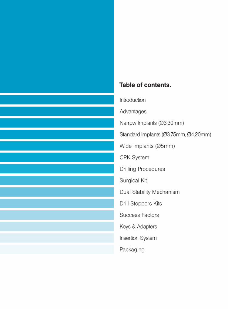
Introduction
Advantages
Narrow Implants (Ø3.30mm)
Standard Implants (Ø3.75mm, Ø4.20mm)
Wide Implants (Ø5mm)
CPK System
Drilling Procedures
Surgical Kit
Dual Stability Mechanism
Drill Stoppers Kits
Success Factors
Keys & Adapters
Insertion System
Packaging
Table of contents.
4.
© MIS Corporation. All rights reserved.
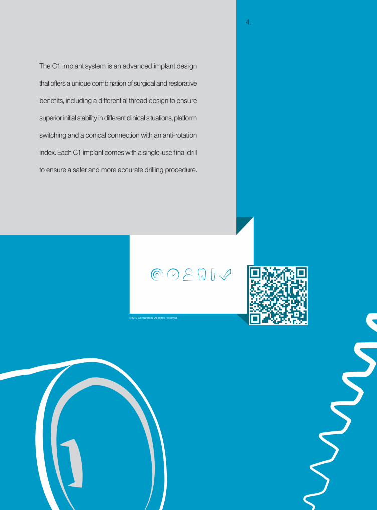
The C1 implant system is an advanced implant design
that offers a unique combination of surgical and restorative
benefits, including a differential thread design to ensure
superior initial stability in different clinical situations, platform
switching and a conical connection with an anti-rotation
index. Each C1 implant comes with a single-use final drill
to ensure a safer and more accurate drilling procedure.

6.
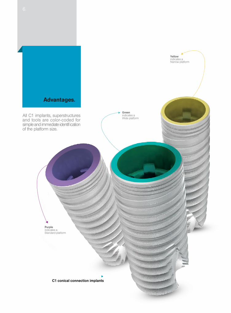
Advantages.
C1 conical connection implants
All C1 implants, superstructures and tools are color-coded for simple and immediate identification of the platform size.
Advantages.
Greenindicates a Wide platform
Purpleindicates a Standard platform
Yellow indicates a Narrow platform

Surface treatmentC1 implants are sand-blasted and acid-etched. These surface treatments increase the implant surface area by creating both micro and nano-structures and eliminating various surface contaminants.
The C1 implantFeaturing a 6-degree conical connection that ensures a secure fit between abutment and implant, the C1 minimizes micro-movements reducing bone loss at the crestal level. It has is a six-position cone index within the conical connection to help orient the implant during insertion as well as placing the abutment into the proper position.
Conical shapeWith its conical, root-shaped geometry and a unique thread design, C1 ensures a superior primary stability and offers the ultimate choice for a wide range of clinical cases and loading protocols ▪ Its root-shaped design makes C1 ideal for narrow spaces, restricted by adjacent teeth or implants.
Two spiral channels and domed apexThe C1 features a domed apex, providing a high tolerance and safe procedure during insertion. Two cutting blades at the implant apex establish the self-tapping properties of the C1; supporting a simpler, safer and faster procedure.
Platform switchingThe C1 platform switching keeps the implant-abutment connection away from the bone; minimizing bone resorption. Platform switching additionally allows more vital growth of the soft tissue.
Micro-ringsAt the neck of the C1, micro-rings significantly increase the BIC (Bone to Implant Contact), avoiding bone resorption at the crestal zone.
Dual threadThe C1 dual thread design increases the BIC (Bone to Implant Contact) over the entire body of the implant. The dual thread doubles the implant insertion rate (1.50mm), facilitating a simpler and faster implant placement.
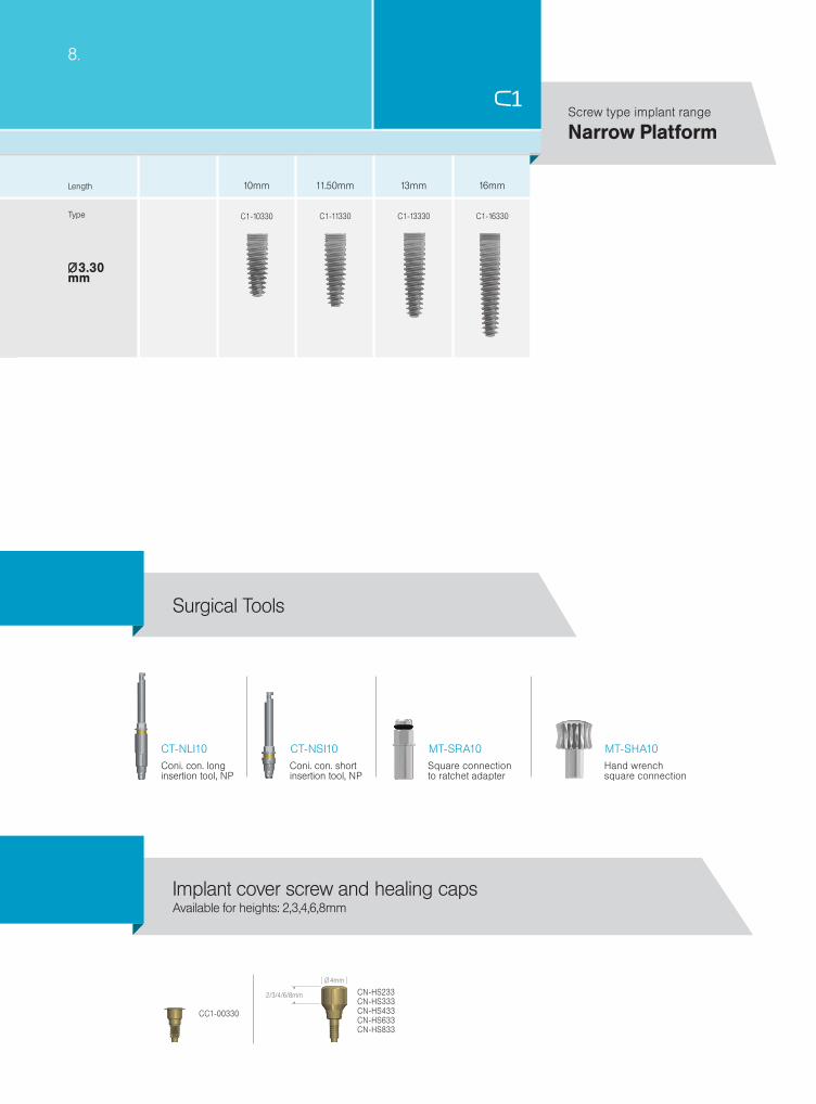
16mm11.50mm 13mm10mm
Ø3.30mm
8.
C1-10330 C1-13330 C1-16330C1-11330
CC1-00330
2/3/4/6/8mm
Ø 4mm
CN-HS233CN-HS333CN-HS433CN-HS633 CN-HS833
MT-SRA10 MT-SHA10CT-NLI10 CT-NSI10
Narrow PlatformScrew type implant range
Length
Type
Available for heights: 2,3,4,6,8mmImplant cover screw and healing caps
Square connectionto ratchet adapter
Hand wrenchsquare connection
Coni. con. longinsertion tool, NP
Coni. con. shortinsertion tool, NP
Surgical Tools
Ø 2.50
Ø 3.30
Ø2.4
Ø 3.2
Ø2.75
1200-1500
900-1200
Ø1.90 Ø3.30Ø2.40 Ø2.40
15-25Ø3 Ø3.60
200-400
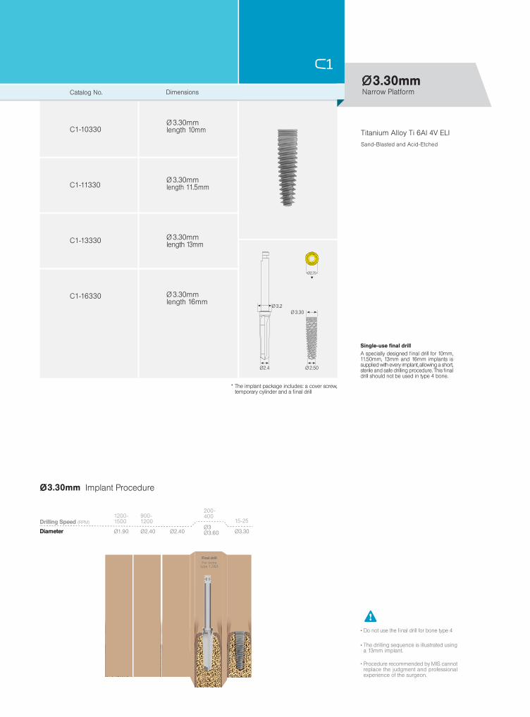
C1-10330
C1-11330
C1-13330
C1-16330
Ø3.30mm
Ø3.30mm
Ø 3.30mm
Ø 3.30mm
Ø 3.30mm
Ø 3.30mm
Catalog No. Dimensions
length 10mm
length 11.5mm
length 16mm
length 13mm
Single-use final drill A specially designed final drill for 10mm, 11.50mm, 13mm and 16mm implants is supplied with every implant, allowing a short, sterile and safe drilling procedure. This final drill should not be used in type 4 bone.
* The implant package includes: a cover screw, temporary cylinder and a final drill
Titanium Alloy Ti 6Al 4V ELISand-Blasted and Acid-Etched
Narrow Platform
Drilling Speed (RPM)
Diameter
Final drill For bonetype 1,2&3
Implant Procedure
The drilling sequence is illustrated using a 13mm implant.
Procedure recommended by MIS cannot replace the judgment and professional experience of the surgeon.
Do not use the final drill for bone type 4
10.
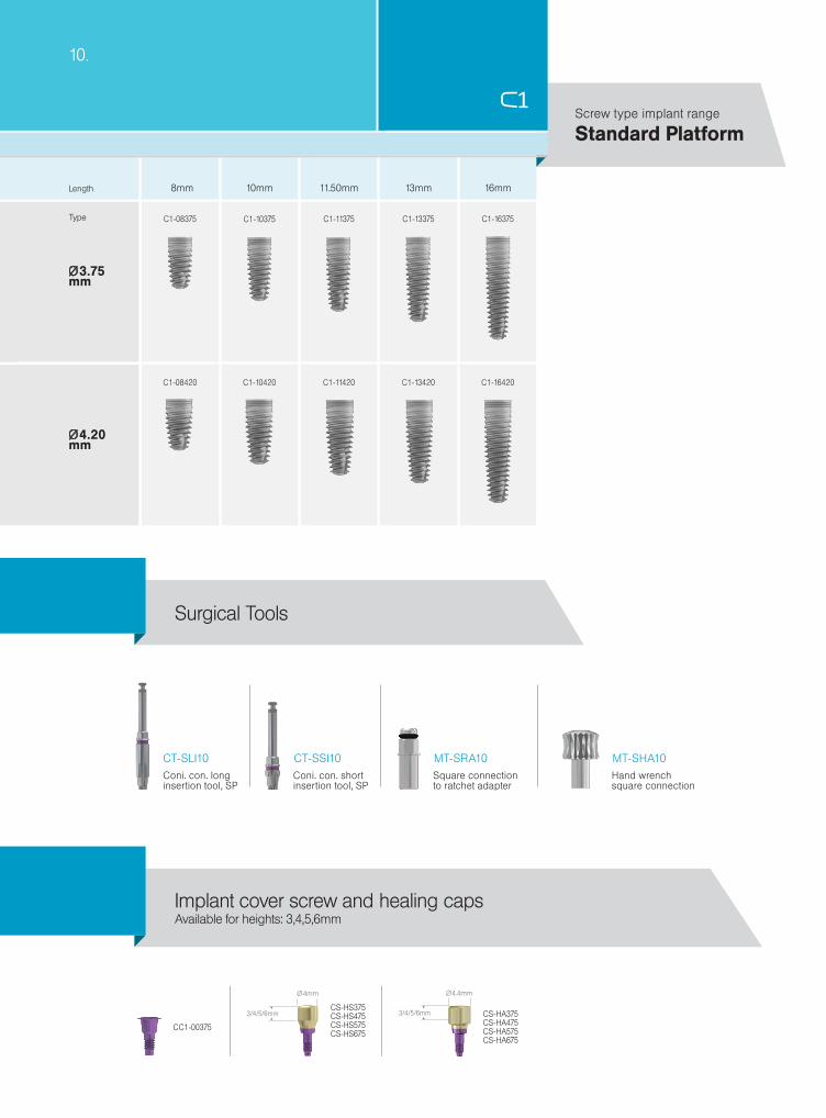
C1-10375 C1-13375 C1-16375
C1-10420 C1-11420 C1-13420 C1-16420
C1-11375C1-08375
C1-08420
16mm11.50mm 13mm8mm 10mm
Ø3.75mm
Ø4.20mm
CC1-00375
CS-HS375CS-HS475CS-HS575CS-HS675
3/4/5/6mm
Ø 4mm
CS-HA375CS-HA475CS-HA575CS-HA675
3/4/5/6mm
Ø 4.4mm
MT-SRA10 MT-SHA10CT-SLI10 CT-SSI10
Available for heights: 3,4,5,6mmImplant cover screw and healing caps
Surgical Tools
Standard PlatformScrew type implant range
Length
Type
Square connectionto ratchet adapter
Hand wrenchsquare connection
Coni. con. longinsertion tool, SP
Coni. con. shortinsertion tool, SP

Ø 3.10
Ø 3.75
Ø3
Ø 3.60
Ø3.15
C1-08375
C1-16375
C1-10375
C1-11375
C1-13375
Ø3.75mm
Ø 3.75mm
Ø 3.75mm
Ø 3.75mm
Ø 3.75mm
Ø 3.75mm
1200-1500
900-1200
Ø1.90 Ø3 Ø3.75Ø2.40 Ø2.40
500-700 15-25
Ø3 Ø3.60
200-400
Ø3
Ø3.75mm
Single-use final drill A specially designed final drill for 8mm, 10mm, 11.50mm, 13mm and 16mm implants is supplied with every implant, allowing a short, sterile and safe drilling procedure. This final drill should not be used in type 4 bone.
Standard PlatformCatalog No. Dimensions
length 8mm
length 10mm
length 13mm
length 16mm
* The implant package includes: a cover screw, temporary cylinder and a final drill
The drilling sequence is illustrated using a 13mm implant.
Procedure recommended by MIS cannot replace the judgment and professional experience of the surgeon.
Do not use the final drill for bone type 4
Titanium Alloy Ti 6Al 4V ELISand-Blasted and Acid-Etched
Implant Procedure
Drilling Speed (RPM)
Diameter
For bonetype 1,2&3
Final drill
length 11.50mm
Ø4.20mm
Ø3.50
Ø4
Ø 3.60
Ø 4.20
Ø3.15
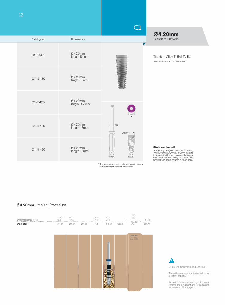
C1-08420
C1-16420
C1-10420
C1-11420
C1-13420
Ø 4.20mm
Ø 4.20mm
Ø 4.20mm
Ø 4.20mm
Ø 4.20mm
12.
Ø4.20mm
1200-1500
900-1200
Ø2.40 Ø3Ø1.90 Ø2.40
500-700
Ø3.50 Ø3.50
400-700
Ø3.50Ø4
200-400
Ø4.20
15-25Drilling Speed (RPM)
Diameter
For bonetype 1,2&3
Final drill
Implant Procedure
Titanium Alloy Ti 6Al 4V ELISand-Blasted and Acid-Etched
Standard Platform
Single-use final drill A specially designed final drill for 8mm, 10mm, 11.50mm, 13mm and 16mm implants is supplied with every implant, allowing a short, sterile and safe drilling procedure. This final drill should not be used in type 4 bone.
The drilling sequence is illustrated using a 13mm implant.
Procedure recommended by MIS cannot replace the judgment and professional experience of the surgeon.
Do not use the final drill for bone type 4
* The implant package includes: a cover screw, temporary cylinder and a final drill
Catalog No. Dimensions
length 8mm
length 10mm
length 13mm
length 16mm
length 11.50mm
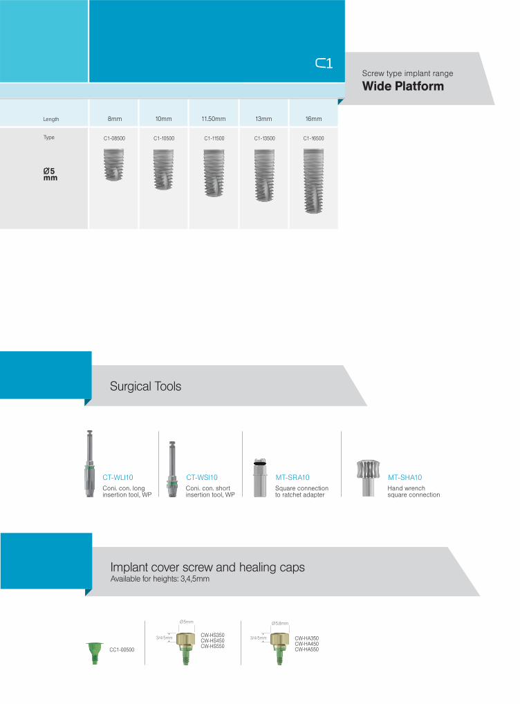
CC1-00500
CW-HS350CW-HS450CW-HS550
3/4/5mm
Ø 5mm
3/4/5mm CW-HA350CW-HA450CW-HA550
Ø 5.8mm
16mm11.50mm 13mm8mm 10mm
Ø5mm
C1-08500 C1-10500 C1-11500 C1-13500 C1-16500
MT-SRA10 MT-SHA10CT-WLI10 CT-WSI10
Length
Type
Wide PlatformScrew type implant range
Available for heights: 3,4,5mmImplant cover screw and healing caps
Square connectionto ratchet adapter
Hand wrenchsquare connection
Coni. con. longinsertion tool, WP
Coni. con. shortinsertion tool, WP
Surgical Tools

Ø5mm
C1-08500
C1-16500
C1-10500
C1-11500
C1-13500
Ø 5
Ø 4.50Ø 4.10
Ø 4.90
Ø4
Ø 5mm
Ø 5mm
Ø 5mm
Ø5mm
Ø 5mm
Ø4.10 Ø 4.90
200-400
Ø5
15-25
Ø4
400-600
1200-1500
900-1200
Ø2.40 Ø3 Ø3.50Ø2.40Ø1.90
500-700
400-700
Ø5mm
Ø4
14.
Drilling Speed (RPM)
For bonetype 1,2&3
Final drill
Implant Procedure
Wide Platform
Single-use final drill A specially designed final drill for 8mm, 10mm, 11.50mm, 13mm and 16mm implants is supplied with every implant, allowing a short, sterile and safe drilling procedure. This final drill should not be used in type 4 bone.
The drilling sequence is illustrated using a 13mm implant.
Procedure recommended by MIS cannot replace the judgment and professional experience of the surgeon.
Do not use the final drill for bone type 4
Titanium Alloy Ti 6Al 4V ELISand-Blasted and Acid-Etched
* The implant package includes: a cover screw, temporary cylinder and a final drill
Catalog No. Dimensions
length 8mm
length 10mm
length 13mm
length 16mm
length 11.50mm
Diameter

CK-CPK61CK-CPK62CK-CPK63CK-CPK64
CK-NPK62
CK-WPK61CK-WPK62CK-WPK63CK-WPK64
The Complete Prosthetic Kit (CPK) is a comprehensive set designed for the full restoration of parallel inserted implants and restoration of a single implant case.
CPK - Complete Prosthetic Kit.
STANDARD
NARROW
WIDE
AVAILABLE IN THREE PLATFORMS:

Ø3.75
Ø3.30
Ø4.20
Ø5
SPADE / M
ARKING DRILL Ø1.90mm SPADE / MARKIN
G D
RILL Ø
1.90mm
PILOT DRILL Ø2.40mm PILOT DR
ILL Ø2.40m
m
BODY TRY-IN Ø2.40mm BODY TRY-IN Ø
2.40mm
TWIST DRILL 3mm TW
IST DRILL 3m
m
B
ODY TRY-IN Ø3mm TWIST DR
ILL 3.50mm
FINAL DRILL BODY TRY-IN Ø
3.5mm
FINAL DR
ILL
TWIST DRILL 3.50mm
FINAL DRILL
TWIST DRILL 4mm
FINAL D
RILL TWIST DRILL 3mm
BO
DY TR
Y-IN Ø
2.40mm
BODY TRY-IN Ø2.40mm
PILO
T DR
ILL Ø2.40m
m PILOT DRILL Ø
2.40m
SPAD
E / MAR
KING
DR
ILL Ø1.90m
m SPADE / MARKING DRILL
Ø1.90mm
BODY TRY-IN Ø4m
m
C1 IMPLANT
16.
Procedure recommended by MIS cannot replace the judgment and professional experience of the surgeon.
Initial surgical steps are common for all implant diameters. Additional steps are required as the implant diameter increases.
DrillingProcedures.
Ø3.75
Ø3.30
Ø4.20
Ø5
SPADE / M
ARKING DRILL Ø1.90mm SPADE / MARKIN
G D
RILL Ø
1.90mm
PILOT DRILL Ø2.40mm PILOT DR
ILL Ø2.40m
m
BODY TRY-IN Ø2.40mm BODY TRY-IN Ø
2.40mm
TWIST DRILL 3mm TW
IST DRILL 3m
m
B
ODY TRY-IN Ø3mm TWIST DR
ILL 3.50mm
FINAL DRILL BODY TRY-IN Ø
3.5mm
FINAL DR
ILL
TWIST DRILL 3.50mm
FINAL DRILL
TWIST DRILL 4mm
FINAL D
RILL TWIST DRILL 3mm
BO
DY TR
Y-IN Ø
2.40mm
BODY TRY-IN Ø2.40mm
PILOT D
RILL Ø
2.40mm
PILOT DRILL Ø2.40m
SPAD
E / MAR
KING
DR
ILL Ø1.90m
m SPADE / MARKING DRILL
Ø1.90mm
BODY TRY-IN Ø4m
m
C1 IMPLANT
STANDARD
NARROW
WIDE
Ø1.90 Ø2.40 Ø3Ø2.40 Ø3 Ø3.50 Ø4Ø4Ø3.50
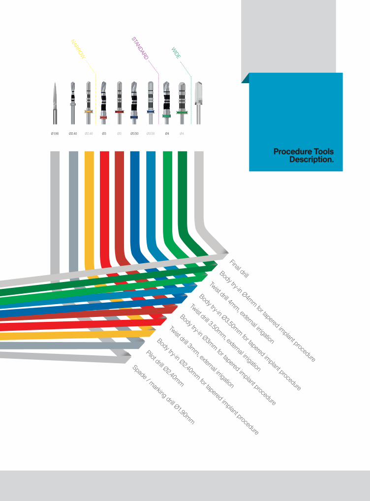
Procedure Tools Description.
Spade / marking drill Ø1.90mm
Body try-in Ø2.40mm for tapered implant procedure
Body try-in Ø3mm for tapered implant procedure
Twist drill 3mm, external irrigation
Twist drill 3.50mm, external irrigation
Twist drill 4mm, external irrigation
Final drill
Body try-in Ø3.50mm for tapered implant procedure
Body try-in Ø4mm for tapered implant procedurePilot drill Ø2.40mm
18.
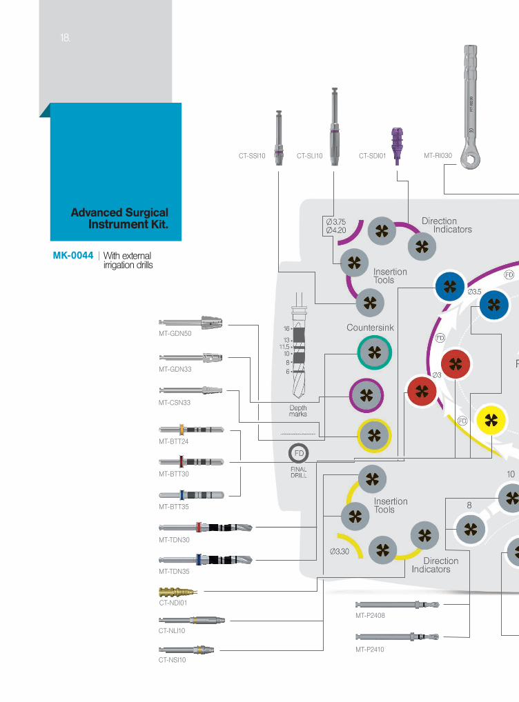
MK-0044
MT-GDN33
MT-GDN50
MT-RI030
MT-TDN30
MT-TDN35
CT-SDI01CT-SLI10CT-SSI10
MT-BTT24
MT-BTT30
MT-BTT35
MT-P2408
MT-P2410
MT-CSN33
CT-NDI01
CT-NLI10
CT-NSI10
With external irrigation drills
Advanced Surgical Instrument Kit.

MT-SMD10
MT-TDN19
CT-WDI01 CT-WLI10CT-WSI10MT-BTT40 MT-BTT45 MT-BTT50
MT-SM005
MT-DE001
MT-SHA10
MT-PP240
MT-P2411
MT-P2413
MT-P2416
MT-LM005
MT-SRA10
MT-TDN40
MT-TDT45
MT-TDN50

13.
.
MECHANICAL STABILITY BIOLOGICAL STABILITY
Thanks to a unique drilling methodology,
the implant's geometric design enables a moderate compression of the bone at the top 2/3 of its body. This congestion, enabled by a distinctive conical shaped final drill, provides an immediate and
prolonged mechanical primary stability.
A n e n h a n c e d secondary biological stability
is achieved by integration of the implant's geometry, morphology and
a differential drilling approach. The compartments formed between the implant's threads at the bottom 1/3 of the cavity, generate an ideal habitat
for sustainable bone growth leading to an accelerated
osseointegration.
The Dual Stability Mechanism
the C1 offers a Dual Stability Mechanism (DSM). The DSM combines the benefits of high primary stability with an accelerated osseointegration process, minimizing the
DIP. Enabling moderate compression of the bone at the top 2/3 of the implant body, the conical geometry provides an immediate mechanical primary stability, while the apical 1/3 enables rapid bone growth, minimizing stability
loss during the first weeks after surgery. The secondary stability mechanism is achieved through the differential drilling, that forms specially designed 'compartments' between the implant thread at its apical part; up to one third of
Thanks to a unique drilling methodology, the implant's
geometric design enables a moderate compression of the bone at the top 2/3 of the body. This compression, enabled by a distinctive conical shaped final drill,
provides an immediate and prolonged mechanical primary stability.

16.
MECHANICAL STABILITY BIOLOGICAL STABILITY
Thanks to a unique drilling methodology,
the implant's geometric design enables a moderate compression of the bone at the top 2/3 of its body. This congestion, enabled by a distinctive conical shaped final drill, provides an immediate and
prolonged mechanical primary stability.
A n e n h a n c e d secondary biological stability
is achieved by integration of the implant's geometry, morphology and
a differential drilling approach. The compartments formed between the implant's threads at the bottom 1/3 of the cavity, generate an ideal habitat
for sustainable bone growth leading to an accelerated
osseointegration.
the implant body. These 'compartments' prevent bone compression around the area of the implant, providing an ideal habitat for accelerated and sustainable bone growth and osseointegration.
An enhanced secondary biological stability is achieved by
integration of the implant's geometry, morphology and a differential drilling approach. The compartments formed between the implant's threads at the bottom 1/3 of the cavity generate an ideal habitat for sustainable bone growth leading
to accelerated osseointegration.
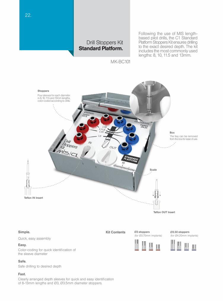
22.
Stoppers
Four sleeves for each diameter in 8, 10, 11.5 and 13mm lengths, color-coded according to drills.
BoxThe tray can be removed from the box for ease of use.
Scale
Teflon OUT Insert
Teflon IN Insert
Simple.
Quick, easy assembly
Kit Contents Ø3 stoppers(for Ø3.75mm implants)
Ø3.50 stoppers(for Ø4.20mm implants)
Easy.Color-coding for quick identification of the sleeve diameter
Safe. Safe drilling to desired depth
Fast.Clearly arranged depth sleeves for quick and easy identification of 8-13mm lengths and Ø3, Ø3.5mm diameter stoppers.
Following the use of MIS length-based pilot drills, the C1 Standard Platform Stoppers Kit ensures drilling to the exact desired depth. The kit includes the most commonly used lengths: 8, 10, 11.5 and 13mm.
Drill Stoppers Kit Standard Platform.
MK-BC101

8mm10mm
11.5mm13mm
MK-CDS08 MK-CDS10
MK-CDS11 MK-CDS13
Simple.
Quick, easy assembly
For 8mm implants For 10mm implants
For 11.5mm implants For 13mm implants
Kit Contents
Scale
Box
Stoppers
The tray can be removed from the box for ease of use.
Five sleeves 3.0, 3.5, 4, 4.5 and 5mm diameters, color-coded according to drills
Desireddrilling depth
Teflon OUT Insert
Teflon IN Insert
Easy.Color coding for a quick identification of sleeve diameter
Safe. Safe drilling to desired depth
Fast.Clearly arranged depth sleeves for quick and easy identification of Ø3mm to Ø5mm diameter drills
Following the use of MIS length-based pilot drills, the C1 Drill Stoppers Length Kits enable safe and easy drilling to the exact desired depth. MIS offers 4 different kits in lengths of: 8, 10, 11.5 and 13mm.
Drill Stoppers Kits Depth Based.

Advantages.
24.
Micro Structure - Surface Morphology
The surface roughness and microgeometry is achieved by sand-blasting and acid-etching. A larger surface area increases bone-to-implant contact (BIC), resulting in a long term clinical success.
A high success rate is achieved through a combination of advanced geometric design and our well-established surface morphology.
Success.

20
15
10
5
0
Microgram
Implant
Jerusalem, Israel, IADRAugust 03, 2004
Hebrew University
Adsorption of Serum Protein to Modified Titanium SurfacesM.N. Sela, L.Badihi, G.Rosen, D.Kohavi and D. Steinberg
The use of Titanium (Ti) implants is a novel clinical procedure in dentistry. The adsorption of biological molecules to the implant’s surface triggers a sequence of events that may determine the outcome of this procedure. Clinical data suggests that modified Ti surfaces play an important role in the success or failure of the implant. Objective: the purpose of this study was to investigate the interaction between Ti implants with different surface properties and serum proteins, in order to find the optimal implant surfaces which may improve the Osseointegration process and implant intake.
Materials & Methods: Six mm in diameter Ti disks with two types of surface modifications were compared: Machined and Sandblast plus Acid-Etched. The disks were coated with mixtures of Human Serum Albumin conjugated with fluorescein (HAS-FITC).
Following incubation, the coat was removed from the disks by SDS. A Confocal Scanning Laser Microscope was used to visualize and measure the HAS-FITC coat and the degree of protein removal from the Ti surfaces.
Results: The Confocal Microscope images revealed a significantly higher amount of HAS-FITC coat on the rough disks, as compared with the machined disks. Furthermore, under similar experimental conditions, less HAS-FITC could be removed from the rough disks than from the machined disks.
Conclusions: Absorption of albumin to the rough treated Ti surface is both qualitatively and quantitatively far more intense, as compared with the machined surfaces. Further studies of the chemical and physical characterization of the modified Ti surfaces are underway. Moreover, additional serum proteins, as well as oral microorganisms, are being examined for their interactions with the modified Ti surfaces.
Albumin
IGG
Fibronectin
Fibrinogen
Machine
Machine
MIS surface

22.20.26.
MT-SRA10
CT-SLI10
CT-SSI10
MT-SHA10
MT-LM005
MT-SM005
Squ
are
conn
ectio
n to
rat
chet
ada
pter
Han
d w
renc
h sq
uare
con
nect
ion
Long
mot
or a
dapt
er fo
r 0.
05"
hex.
Sho
rt m
otor
ada
pter
for
0.05
" he
x.
Long
inse
rtio
n to
ol, S
P
Sho
rt in
sert
ion
tool
, SP
C1 implant placement tools are specially designed to facilitate quick and reliable implant procedures.
Keys & Adapters.
Standard platform tools shown

13
2
1
2
3
20.
Insertion tool in hand key adapter
Insertion tool for motor
Insertion tool in ratchet adapter
The unique "3 in One" insertion system minimizes the number of tools in the surgical kit and maximizes flexibility for the user.
"3 in One" Insertion System.
Insertion Options.
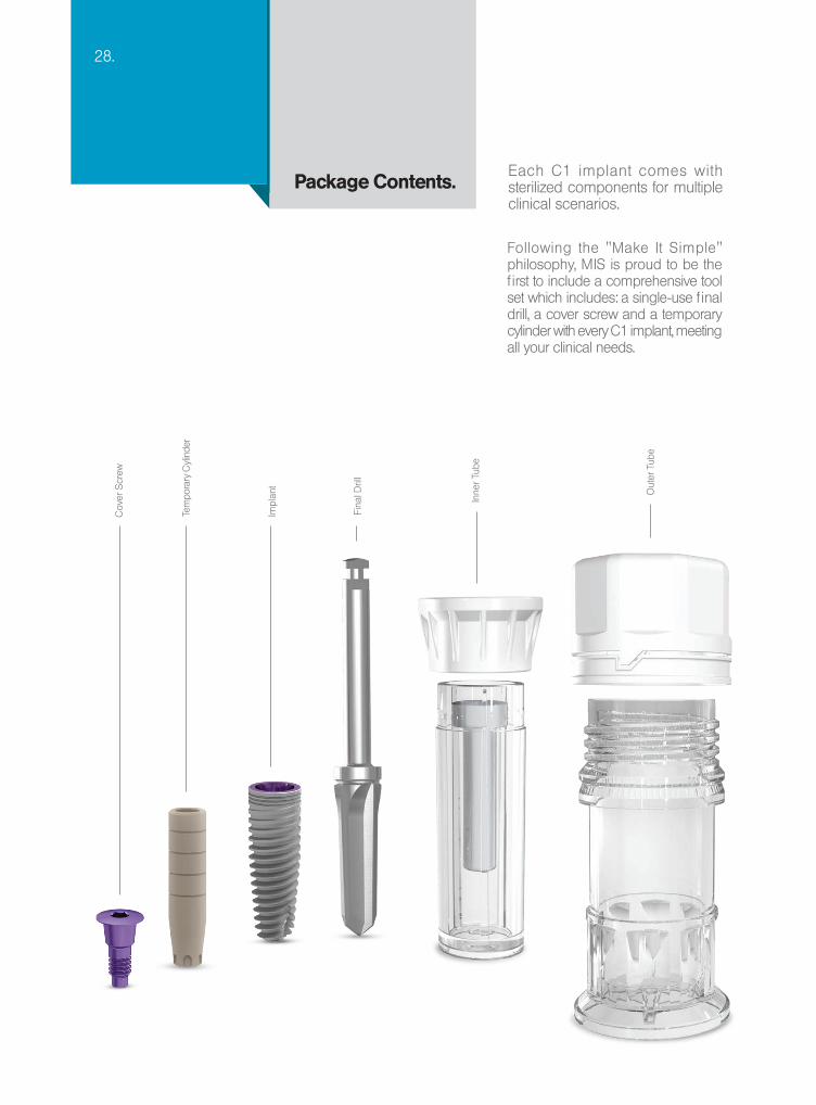
28.
Each C1 implant comes with sterilized components for multiple clinical scenarios.
Package Contents.
Cov
er S
crew
Fina
l Dril
l
Inne
r Tub
e
Out
er T
ube
Impl
ant
Tem
pora
ry C
ylin
der
Following the "Make It Simple" philosophy, MIS is proud to be the first to include a comprehensive tool set which includes: a single-use final drill, a cover screw and a temporary cylinder with every C1 implant, meeting all your clinical needs.
12.
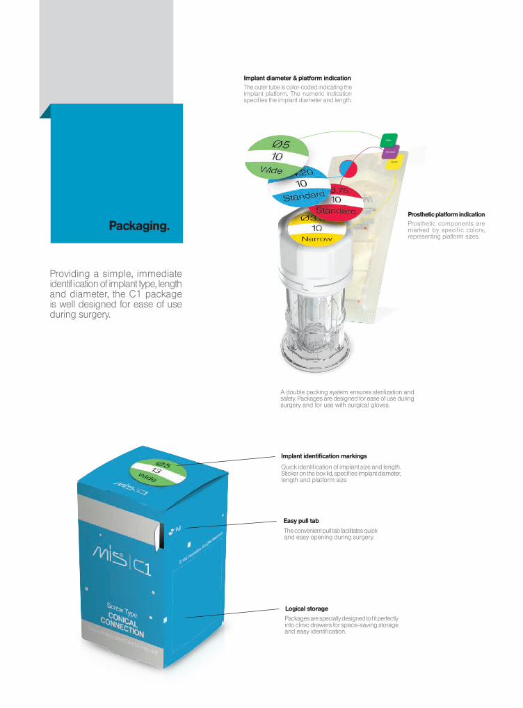
Packaging.
Easy pull tab
Implant identification markings
Logical storage
The convenient pull tab facilitates quick and easy opening during surgery.
Packages are specially designed to fit perfectly into clinic drawers for space-saving storage and easy identification.
Quick identification of implant size and length. Sticker on the box lid, specifies implant diameter, length and platform size
Providing a simple, immediate identification of implant type, length and diameter, the C1 package is well designed for ease of use during surgery.
A double packing system ensures sterilization and safety. Packages are designed for ease of use during surgery and for use with surgical gloves.
Implant diameter & platform indicationThe outer tube is color-coded indicating the implant platform. The numeric indication specifies the implant diameter and length.
Prosthetic platform indicationProsthetic components are marked by specific colors, representing platform sizes.


® All rights reserved. No part of this publication may be reproduced, transcribed, stored in an electronic retrieval system, translated into any language or computer language, or be transmitted in any form whatsoever, without the prior written consent of the publisher.
Authorized European Representative:MIS Germany, Paulinenstraße 12a, 32427 Minden, GERMANY
0483
© MIS Corporation. All Rights Reserved.
MIS Implants Technologies Ltdwww.mis-implants.com
MC
-UN
O08 R
ev.1M
C-U
NO
08 Rev.1
© MIS Corporation. All rights reserved.
The MIS Quality System complies with international
quality standards: ISO 13485:2003 - Quality
Management System for Medical Devices, ISO
9001: 2008 - Quality Management System and
CE Directive for Medical Devices 93/42/EEC. MIS
products are cleared for marketing in the USA
and CE approved.MIS Implants Technologies Ltd.www.mis-implants.com
®
MC
-CO
NE
N R
ev.11