Embed Size (px)
Citation preview
Manualdevolo Magic 2 LAN 1-1

N1-1
devolo Magic 2 LA

© 2019 devolo AG Aachen (Germany) While the information in this manual has been compiled with great care, it may not be deemed an assurance of product characte-
product and the use of its contents is that arise as the result of technical de-
ve owners. Subject to change without
ristics. devolo shall be liable only to the degree specified in the terms of sale and delivery.The reproduction and distribution of the documentation and software supplied with thissubject to written authorization from devolo. We reserve the right to make any alterationsvelopment.
TrademarksAndroid TM is a registered trademark of Open Handset Alliance.Linux® is a registered trademark of Linus Torvalds.Ubuntu®is a registered trademark of Canonical Ltd. Mac® and Mac OS X® are registered trademarks of Apple Computer, Inc.iPhone®,iPad® and iPod® are registered trademarks of Apple Computer, Inc.
Windows® and Microsoft® are registered trademarks of Microsoft, Corp.devolo, dLAN® and the devolo logo are registered trademarks of devolo AG. All other names mentioned may be trademarks or registered trademarks of their respectinotice. No liability for technical errors or omissions.
devolo AGCharlottenburger Allee 6752068 AachenGermanywww.devolo.com
Version 1.2_10/19

devolo Magic 2 LAN 1-1
. . . . . . . . . . . . . . . . . . . . . . . . . . . . . . . . 6 . . . . . . . . . . . . . . . . . . . . . . . . . . . . . . . . 6 . . . . . . . . . . . . . . . . . . . . . . . . . . . . . . . . 7 . . . . . . . . . . . . . . . . . . . . . . . . . . . . . . . . 8 . . . . . . . . . . . . . . . . . . . . . . . . . . . . . . . . 8 . . . . . . . . . . . . . . . . . . . . . . . . . . . . . . . . 9
. . . . . . . . . . . . . . . . . . . . . . . . . . . . . . . 10 . . . . . . . . . . . . . . . . . . . . . . . . . . . . . . . 10 . . . . . . . . . . . . . . . . . . . . . . . . . . . . . . . 11 . . . . . . . . . . . . . . . . . . . . . . . . . . . . . . . 12 . . . . . . . . . . . . . . . . . . . . . . . . . . . . . . . 14 . . . . . . . . . . . . . . . . . . . . . . . . . . . . . . . 17 . . . . . . . . . . . . . . . . . . . . . . . . . . . . . . . 17
. . . . . . . . . . . . . . . . . . . . . . . . . . . . . . . 18 . . . . . . . . . . . . . . . . . . . . . . . . . . . . . . . 18 . . . . . . . . . . . . . . . . . . . . . . . . . . . . . . . 18 . . . . . . . . . . . . . . . . . . . . . . . . . . . . . . . 19gic network . . . . . . . . . . . . . . . . . . 19
ng another devolo Magic . . . . . . . . . . . . . . . . . . . . . . . . . . . . . . . 20 . . . . . . . . . . . . . . . . . . . . . . . . . . . . . . . 20 . . . . . . . . . . . . . . . . . . . . . . . . . . . . . . . 20 . . . . . . . . . . . . . . . . . . . . . . . . . . . . . . . 21
Contents1 Preface . . . . . . . . . . . . . . . . . . . . . . . . . . . . . . . . . . . . . . . . . . . . . . . . . . . . .
1.1 About this manual . . . . . . . . . . . . . . . . . . . . . . . . . . . . . . . . . . . . .1.2 Intended use . . . . . . . . . . . . . . . . . . . . . . . . . . . . . . . . . . . . . . . . . .1.3 CE Conformity . . . . . . . . . . . . . . . . . . . . . . . . . . . . . . . . . . . . . . . . .1.4 Safety notes . . . . . . . . . . . . . . . . . . . . . . . . . . . . . . . . . . . . . . . . . . .1.5 devolo on the Internet . . . . . . . . . . . . . . . . . . . . . . . . . . . . . . . . .
2 Introduction . . . . . . . . . . . . . . . . . . . . . . . . . . . . . . . . . . . . . . . . . . . . . . . .2.1 devolo Magic . . . . . . . . . . . . . . . . . . . . . . . . . . . . . . . . . . . . . . . . .2.2 Introduction to the devolo Magic adapter: . . . . . . . . . . . . . .2.3 Pairing . . . . . . . . . . . . . . . . . . . . . . . . . . . . . . . . . . . . . . . . . . . . . . . .
2.3.1 Reading the indicator light . . . . . . . . . . . . . . . . . . . . . .2.3.2 Network connection . . . . . . . . . . . . . . . . . . . . . . . . . . .2.3.3 Integrated electrical socket . . . . . . . . . . . . . . . . . . . . .
3 Initial use . . . . . . . . . . . . . . . . . . . . . . . . . . . . . . . . . . . . . . . . . . . . . . . . . . .3.1 Package contents . . . . . . . . . . . . . . . . . . . . . . . . . . . . . . . . . . . . . .3.2 System requirements . . . . . . . . . . . . . . . . . . . . . . . . . . . . . . . . . .3.3 Connecting the devolo Magic 2 LAN 1-1 . . . . . . . . . . . . . . . . .
3.3.1 Starter Kit – Automatic set-up for a new devolo Ma3.3.2 Addition – Expanding an existing network by addi
adapter . . . . . . . . . . . . . . . . . . . . . . . . . . . . . . . . . . . . . . . .3.3.3 Changing the network password . . . . . . . . . . . . . . . .
3.4 Installation of devolo software . . . . . . . . . . . . . . . . . . . . . . . . .3.5 Removing the devolo Magic adapter from a network . . . .

dev
. . . . . . . . . . . . . . . . . . . . . . . . . . . . . . . 22 . . . . . . . . . . . . . . . . . . . . . . . . . . . . . . . 22 . . . . . . . . . . . . . . . . . . . . . . . . . . . . . . . 22 . . . . . . . . . . . . . . . . . . . . . . . . . . . . . . . 24 . . . . . . . . . . . . . . . . . . . . . . . . . . . . . . . 26 . . . . . . . . . . . . . . . . . . . . . . . . . . . . . . . 28 . . . . . . . . . . . . . . . . . . . . . . . . . . . . . . . 29 . . . . . . . . . . . . . . . . . . . . . . . . . . . . . . . 32
. . . . . . . . . . . . . . . . . . . . . . . . . . . . . . . 33 . . . . . . . . . . . . . . . . . . . . . . . . . . . . . . . 33 . . . . . . . . . . . . . . . . . . . . . . . . . . . . . . . 33 . . . . . . . . . . . . . . . . . . . . . . . . . . . . . . . 34 . . . . . . . . . . . . . . . . . . . . . . . . . . . . . . . 34
olo Magic 2 LAN 1-1
4 Configuration . . . . . . . . . . . . . . . . . . . . . . . . . . . . . . . . . . . . . . . . . . . . . .4.1 Calling up the built-in web interface . . . . . . . . . . . . . . . . . . . .4.2 Menu description . . . . . . . . . . . . . . . . . . . . . . . . . . . . . . . . . . . . . .
4.2.1 Overview . . . . . . . . . . . . . . . . . . . . . . . . . . . . . . . . . . . . . .4.2.2 Powerline . . . . . . . . . . . . . . . . . . . . . . . . . . . . . . . . . . . . . .4.2.3 LAN . . . . . . . . . . . . . . . . . . . . . . . . . . . . . . . . . . . . . . . . . . .4.2.4 System . . . . . . . . . . . . . . . . . . . . . . . . . . . . . . . . . . . . . . . .4.2.5 Reboot . . . . . . . . . . . . . . . . . . . . . . . . . . . . . . . . . . . . . . . .
5 Appendix . . . . . . . . . . . . . . . . . . . . . . . . . . . . . . . . . . . . . . . . . . . . . . . . . . .5.1 Technical specifications . . . . . . . . . . . . . . . . . . . . . . . . . . . . . . . .5.2 Bandwidth optimization . . . . . . . . . . . . . . . . . . . . . . . . . . . . . . .5.3 Disposal of old devices . . . . . . . . . . . . . . . . . . . . . . . . . . . . . . . . .5.4 Warranty conditions . . . . . . . . . . . . . . . . . . . . . . . . . . . . . . . . . . .

Preface 6
devolo Magic 2 LAN 1-1
f the icons
contains a brief description of thethis manual and/or on the rating pla- connector, as well as the icons used
ge:
Description
Very important safety symbol thatwarns you of imminent electricalvoltage which if not observed canresult in serious injury or death.
An important safety symbol thatwarns you of a potentially dange-rous situation involving a burn ha-zard which can result in minorinjuries or damage to property.
An important note that should beobserved which can potentiallylead to material damages.
The device may only be used in-doors in dry conditions.
1 PrefaceWelcome to the fantastic world of devolo Magic! In no time at all, devolo Magic transforms yourhouse into a multimedia home that is ready for thefuture today. devolo Magic gives you noticeablyhigher speeds, more stability and greater range,providing the perfect Internet experience as a re-sult!
1.1 About this manualCarefully read all instructions before setting up thedevice and store the manual and/or installationguide for later reference.
After a brief introduction to „devolo Magic“ and tothe devolo Magic 2 LAN 1-1 in Chapter 2,Chapter 3 tells you how to successfully start usingthe adapter in your network.
Chapter 4 describes in detail the setting options ofthe built-in configuration interface.
Tips for bandwidth optimisation, informationabout environmental compatibility of the device,as well as our warranty terms, can be found inChapter 5 at the end of the manual.
Description o
This section icons used in te, the deviceon the packa
Icon

7 Preface
dev
ded useoducts, devolo software and the pro-ries as described to prevent damage
cts are communication devices desi-ors.* Depending on the product, they with a PLC- (PowerLine Communica-a Wi-Fi module. Computers, laptops,, tablets, smart TVs and other devicesis way are integrated into a home the existing electrical wiring and/ort any complicated wiring. devolo de-ever be used outdoors because theature fluctuations and moisture can the product and the power line. de- may not be installed at a height abo-res unless an additional fas-tening available. The products are intended in the EU, Switzerland and Norway.
tions are devolo outdoor products, which aretdoor use thanks to their IP certification.
olo Magic 2 LAN 1-1
1.2 IntenUse devolo prvided accessoand injury.
Productsdevolo produgned for indoare equippedtion) and/or smartphonesconnected thnetwork overWi-Fi withouvices must nhigh temperdamage bothvolo productsve two metmechanism isfor operation
* The only excepsuited for the ou
The manufacturer/distributingcompany uses the CE marking todeclare that the product meets allapplicable European regulationsand has been subjected to the pres-cribed conformity assessmentprocedures.
It is used to prevent the occurrenceof waste electrical and electronicequipment and to reduce this typeof waste through reuse, recyclingand other forms of utilisation. TheEuropean Community WEEE Direc-tive establishes minimum standardsfor handling waste electrical andelectronic equipment in the EU.
Additional information, backg-round material and configurationtips for your device.
Indicates a completed course of ac-tion
Icon Description

Preface 8
devolo Magic 2 LAN 1-1
the simplified CE declaration of thisparately included and can also be
.com/support/ce.
notesto have read and understood all safe-ing instructions before the devolo de-or the first time; keep them safe force.
ER! Electrical shock caused byicityt reach into the electrical socket, do
pen the device and do not insert anyts into the electrical socket or into theation openings
eed to carry out any maintenance ons. In the event of damage, disconnectvice from the mains supply by pullingut of the electrical socket. Then con- specialist personnel (after-sales ser-ely. Damage is deemed to haveexample,
Softwaredevolo devices can be used only with the free,downloadable programs approved and availableon devolo AG's website (www.devolo.com) and inapp stores (iOS and Google Play). Anymodifications to the product-specific firmware orsoftware could damage the products and, in theworst-case scenario, render them unusable andnegatively affect conformity.
Always use the most up-to-date software versionto make sure you have the latest security functionsand device updates. The installed devolo softwarenotifies you automatically if a new software versi-on is available.
AccessoriesUse only the provided accessories.
1.3 CE ConformityThis product complies with the technicalrequirements of the directives 2014/35/EU, 2014/30/EU, 2011/65/EU und 2009/125/EC.
This product is designed for use in the EU,Switzerland and Norway.
A printout ofproduct is sefound under www.devolo
1.4 SafetyIt is essential ty and operatvice is used ffuture referen
DANGelectrDo nonot oobjecventil
Users do not ndevolo devicethe devolo deit or its plug otact qualifiedvice) exclusivoccurred, for

9 Preface
dev
s should only be installed at locationsee adequate ventilation. Slots andthe housing are used for ventilation:
ver devolo devices during operation.ce any objects on devolo devices.ert any objects into the openings ofvices. vices must not be placed directly
naked flame (such as fire or candles).vices must not be exposed to directtion (e.g. radiator, direct sunlight).ION! Damage to housing from
ing agents containing solvents only electroless and with dry cloth
o on the Internetinformation on our products and
, visit www.devolo.com.
ll find product descriptions and docu-nd also updates of devolo softwareice's firmware.
y further ideas or suggestions relatedts, please don't hesitate to contact usevolo.com!
olo Magic 2 LAN 1-1
b if the power plug is damaged.b if the devolo device has been showered with
liquid (such as rain or other water).b if the devolo device is inoperable.b if the housing of the devolo device is damaged.
Do not plug devolo devices directly into eachother. Devices that are plugged into each othercan experience a decrease in transmission rate.
DANGER! Electric shock caused byelectricity Device must be plugged into a powersocket with a connected earth wire
devolo devices may be operated only on a mainspower supply as described on the rating plate.
To disconnect devolo devices from the mains sup-ply, unplug the device from the electrical socket.The power socket and all connected network de-vices should be easily accessible so that you can pullthe power plug quickly if needed.
CAUTION! Heat development during ope-rationCertain housing components can becomevery hot in certain situations. Attach deviceso that it is touch-proof, observing optimalpositioning
devolo devicethat guarantopenings on
b Do not cob Do not plab Do not ins
devolo deb devolo de
next to a b devolo de
heat radiaCAUTcleanClean
1.5 devolFor detailed devolo Magic
There you wimentation, aand your dev
If you have anto our producat support@d

Introduction 10
devolo Magic 2 LAN 1-1
e perfect Internet experience as a
y products that are astonishingly easyh impressive, innovative technology
ble performance.
2 Introduction
2.1 devolo MagicHome is where devolo Magic is – in no time at all,devolo Magic transforms your house or flat into amultimedia home of the future with noticeablyhigher speed, more stability and greater range,
providing thresult!
Be inspired bto install, witand unbeata
Fig. 1 devolo Magic throughout the home

11 Introduction
dev
uction to the o Magic adapter: g in – get started and be ready forration of tried-and-tested Powerline
stability – thanks to consistent dataon speed at up to 2400 Mbps over
of up to 500 meters, thegic 2 LAN 1-1 promises entertain-e highest level. with 128-bit AES Powerline encryp-
ficiency – the integrated PowerSaves energy consumption automaticallyw data traffic.o Magic 2 LAN 1-1 transforms anysocket in your household electrical a Gigabit LAN Internet access point.
ted electrical socket can be used (likewall socket) to supply power to an
l network device or a power strip. gabit LAN port on thegic 2 LAN 1-1 lets you connect a sta-twork device – such as a game con-ision or media receiver – to your
olo Magic 2 LAN 1-1
Be ready for the technology of the future today
devolo Magic embodies the new generation of thetried-and-tested Powerline technology (PLC) ba-sed on the cutting-edge G.hn architecture. G.hnwas developed by the International Telecommuni-cation Union (ITU) with ongoing development pro-vided primarily by the HomeGrid Forum industryassociation. devolo Magic products are certifiedaccording to HomeGrid standards and are compa-tible with other HomeGrid-certified products.
Like the HomePlug AV technology used in establis-hed devolo dLAN devices, devolo Magic uses thehousehold mains supply for data transmission andsecures ideal performance and stability in locationswhere network cables are not viable or desiredand/or the Wi-Fi frequently falls short due to cei-lings and walls.
To set up a devolo Magic network, you need atleast two devolo Magic devices. For technicalreasons, devices from the devolo Magic seriesare not compatible with dLAN devices.
2.2 Introddevol
Unpack – pluthe new genetechnology:
b Speed andtransmissidistances devolo Mament at th
b Security –tion
b Energy-efmode cutduring lo
b A devolelectrical wiring into
b Its integraa normal additiona
b The Gidevolo Mationary nesole, telev
Introduction 12
devolo Magic 2 LAN 1-1
rated electrical socket
g adapters that are in factory default
. have been purchased or successfullyapter Resetting a devolo Magic ad-oving it from a devolo Magic net-atically start to attempt to pair withlo Magic adapter when reconnected
supply.
agic 2 LAN 1-1 with country-specific power socket
Internet access point over the Powerline net-work (e.g. Internet router).
The devolo Magic 2 LAN 1-1 features b One Gigabit network connectionb One indicator light
The LED status display can be disabled. You canfind more information about this in Chapter 4Configuration or in the product manual for thedevolo Cockpit software available online atwww.devolo.com/cockpit.
b One PLC/reset button (next to the networkconnection)
b One integ
2.3 Pairindevolo Magiccondition, i.ereset (see Chapter or remwork), automanother devoto the mains
Fig. 2: devolo Mconnector and

13 Introduction
dev
evolo Magic adapter pairs automati- button needs to be pressed. The LEDpter now also flashes white.
a short time, the flashing LED beco- steady white light. The devolo Magicer has been successfully integratedour existing devolo Magic network.
pairing operation, only one additionalagic adapter can be added at a time.
ind detailed information about instal-olo Magic adapters in Chapter 3.3ng the devolo Magic 2 LAN 1-1.
evolo Magic adapter or removing olo Magic network
e a devolo Magic adapter from yourgic network and successfully restore
configuration to the factory defaultress and hold the reset button longerconds.
the LED flashes white and then dis-he devolo Magic adapter from theply.
ind that all settings that have alreadye will be lost!
olo Magic 2 LAN 1-1
Starting up a new devolo Magic networkAfter plugging the devolo Magic adapters intoavailable power sockets, a new devolo Magic net-work is established automatically within 3 minutes.
Expanding an existing devolo Magic network by adding another devolo Magic adapterIn order to use a new devolo Magic 2 LAN 1-1 inyour devolo Magic- network, first you have toconnect it to your existing devolo Magic adaptersdevices as a network. This is accomplished by usinga shared password, which can be assigned in va-rious ways:
b Using devolo Cockpit or thedevolo Home Netwok App (see Chapter 3.4Installation of devolo software)
b Using the web interface (see Chapter 4.2.2Powerline)
b Using the PLC/reset button as describedbelow.
1 To do so, plug the new devolo Magic adapterinto an available power socket and, for appro-ximately 1 second, press the PLC/reset buttonon a devolo Magic adapter in your existingdevolo Magic network.
2 The new dcally so noof this ada
After mes aadaptinto y
For each devolo M
You can fling devConnecti
Resetting a dit from a dev
1 To removdevolo Maits entire settings, pthan 10 se
2 Wait untilconnect tmains sup
Keep in mbeen mad

Introduction 14
devolo Magic 2 LAN 1-1
LED status display(web interface*)
Cannot be disabled
adapter wason has beens.
ce again) hasce the last re-devolo Magic
th anothereate a full-bed in Chap-
Cannot be disabled
2.3.1Reading the indicator lightThe integrated indicator light (LED) shows the sta-tus for the devolo Magic 2 LAN 1-1 by illuminatingand/or flashing:
LED Flashing be-haviour
Meaning
1 Red LED Lights up forup to 2 sec.
Start-up process
2 Red LED Flashes at in-tervals of 0.5sec. (on/off)
Status 1: The reset of the devolo Magicsuccessful. The PLC/reset buttpressed and held for 10 second
Status 2: The devolo Magic adapter (onthe factory default settings. Sinset, no pairing with another adapter has taken place. Connect the adapter widevolo Magic adapter to crfledged PLC network as descriter 2.3 Pairing.
15 Introduction
dev
e in standbyccessed over
s of the otherite only for a
twork nodesy be electro-
terference onse, put theo each othernterference.
Can be disabled
in optimum Can be disabled
LED status display(web interface*)
olo Magic 2 LAN 1-1
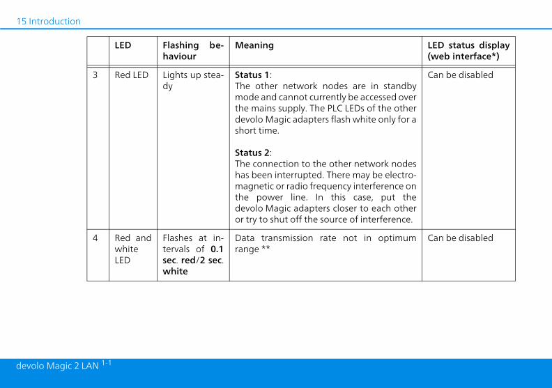
3 Red LED Lights up stea-dy
Status 1: The other network nodes armode and cannot currently be athe mains supply. The PLC LEDdevolo Magic adapters flash whshort time.
Status 2: The connection to the other nehas been interrupted. There mamagnetic or radio frequency inthe power line. In this cadevolo Magic adapters closer tor try to shut off the source of i
4 Red andwhiteLED
Flashes at in-tervals of 0.1sec. red/2 sec.white
Data transmission rate not range **
LED Flashing be-haviour
Meaning

Introduction 16
devolo Magic 2 LAN 1-1
s in pairinghing for new
entify device"ce or in thehis function
dapter being
Cannot be disabled
oes not haveic adapter is
Can be disabled
standby mo- Can be disabled
arrying out a Cannot be disabled
LED status display(web interface*)
5 WhiteLED
Status 1:Flashes at in-tervals of0.5 sec. (on/off)
Status 2:Flashes at in-tervals of1 sec.(on/off)
Status 1: This devolo Magic adapter imode and the system is searcdevolo Magic adapters.
Status 2:Someone has triggered the "Idfunction on the web interfadevolo Home Netwok App. Tidentifies the devolo Magic asought.
6 WhiteLED
Lights up stea-dy
The devolo Magic connection dany issues and the devolo Magready to operate.
7 WhiteLED
Flashes at in-tervals of0.1 sec. on /5 sec. off
The devolo Magic adapter is inde.***
8 Red andwhiteLED
Flashes at in-tervals of0.5 sec. red/0.5 sec. white
The devolo Magic adapter is cfirmware update.
LED Flashing be-haviour
Meaning

17 Introduction
dev
rated electrical sockete integrated electrical socket on the adapter when connecting othero the mains supply. In particular,vices with mains adapter can negati-C performance.
d mains filter in the devolo Magic ad-ny such external interference and re-pairment of PLC performance.
olo Magic 2 LAN 1-1
* Information about the web interface can befound in Chapter 4 Configuration.
** Information on improving the transmission ratecan be found in Chapter 5.2 Bandwidth optimi-zation.
***A devolo Magic adapter switches to standbymode after approximately 10 minutes if no activenetwork device (e.g. computer) is connected to thenetwork interface. In this mode, the devolo Magicadapter cannot be accessed over the electrical wi-ring. As soon as the network device (e.g. computer)connected to the network interface is switched onagain, your devolo Magic adapter can also be ac-cessed over the electrical wiring again.
Check whether the adapter is connected to themains supply correctly and whether the pairingoperation has been carried out successfully. Formore information about this, refer to 3.3Connecting the devolo Magic 2 LAN 1-1.
2.3.2Network connectionYou can use the network connection on thedevolo Magic adapter to connect it to a PC or tele-vision using a standard network cable.
2.3.3IntegAlways use thdevolo Magicconsumers telectronic devely affect PL
The integrateapter filters aduces any im

Initial use 18
devolo Magic 2 LAN 1-1
serves the right to change the packa-ithout prior notice.
requirements systems supported byckpit: indows 7 (32-bit/64-bit),
buntu 13.10 (32-bit/64-bit), ac (OS X 10.9)onnection te that your computer or other devicee a network card or network adaptertwork interface.
a devolo Magic network, you need at devolo Magic adapters.
3 Initial useThis chapter tells you everything you need to knowto set up and use your devolo Magic 2 LAN 1-1. Wedescribe how to connect the adapter and brieflydescribe the devolo software.
3.1 Package contentsPlease ensure that the delivery is complete beforebeginning with the installation of yourdevolo Magic 2 LAN 1-1:
b Starter Kit: a 2 devolo Magic 2 LAN 1-1 a 2 network cables a Hard copy of installation guide a Hard copy security flyer a CE declaration
or
b Extension: a 1 devolo Magic 2 LAN 1-1 a 1 Network cable a Hard copy of installation guide a Hard copy security flyer a CE declaration
devolo AG rege contents w
3.2 Systemb Operating
devolo Co a from W a from U a from M
b Network cPlease nomust havwith a ne
To set upleast two

19 Initial use
dev
ION! Tripping hazardhe network cable in a barrier-freeer and ensure that the electricalt and the connected network de-are easily accessible
devolo Magic adapters into availablekets within 3 minutes. As soon as theoth adapters flash white at regularf 0.5 sec., they are ready to operateatically start the process of establis-
ncrypted connection to each otherter 2.3.1 Reading the indicator
LEDs on both devolo Magic adaptersup in white, then your
o Magic network has been set up ac-g to your individual specifications
protected from unauthorised access.
olo Magic 2 LAN 1-1
3.3 Connecting the devolo Magic 2 LAN 1-1
CAUTION! Damage to the device causedby ambient conditionsOnly use device indoors in dry conditions
In the following sections we describe how toconnect the devolo Magic 2 LAN 1-1 and integrateit into a network. We clarify the exact proceduresbased on potential network scenarios.
For the permitted voltage range for operatingthe device and the power consumption, refer tothe type plate on the rear of the device. For ad-ditional technical information on our products,refer to the product area at www.devolo.com.
3.3.1Starter Kit – Automatic set-up for a new devolo Magic network
1 Connect one devolo Magic 2 LAN 1-1 to yourInternet access device's network connection(e.g. your Internet router).
2 Connect the other devolo Magic 2 LAN 1-1 tothe network connection of your computer oranother network device using a network cable.
CAUTLay tmannsockevices
3 Plug bothpower socLEDs on bintervals oand automhing an e(see Chaplight).
If the light devolcordinand is

Initial use 20
devolo Magic 2 LAN 1-1
e LEDs light up white on botho Magic adapters, the new adaptereen successfully integrated into yourg devolo Magic network.
pairing operation, only one additionalan be added at a time.
ging the network passwordassword can also be changed in theys:
web interface of the devolo Magicee Chapter 4.2.2 Powerline)
devolo Cockpit or theme Network App. For more infor-
fer to the following chapter.
lation of devolo soft-
volo Cockpit softwareit finds all accessible devolo Magicour devolo Magic network, displaysbout these devices and encrypts your network individually. You can use
3.3.2Addition – Expanding an existing network by adding another devolo Magic adapter
Before you can use the devolo Magic 2 LAN 1-1 inyour devolo Magic network, first you have toconnect it to your existing devolo Magic adaptersas a network. This is accomplished by using ashared password.
1 Connect the devolo Magic 2 LAN 1-1 to the net-work connection of your computer or anothernetwork device using a network cable.
2 Plug the devolo Magic 2 LAN 1-1 into an availa-ble power socket. As soon as the LED flasheswhite at regular intervals of 0.5 seconds, theadapter is ready to operate but not yet integra-ted into a devolo Magic network (see Chapter2.3.1 Reading the indicator light).
3 Within 3 minutes, press the PLC/reset buttonon a devolo Magic adapter in your existingdevolo Magic network for approximately 1 sec.
The new devolo Magic adapter pairs automati-cally so no button needs to be pressed. The LEDof this adapter now also flashes white.
If thdevolhas bexistin
For each adapter c
3.3.3ChanA network pfollowing wa
b Using theadapter (s
or
b Using devolo Homation, re
3.4 Instalware
Installing dedevolo Cockpadapters in yinformation adevolo Magic

21 Initial use
dev
find more information about theme Network App online at
volo.com/devolo-app.
ving the devolo Magic er from a network
devolo Magic adapter from your net-cessfully restore its entire configurati-tory default settings, press the PLC/onger than 10 seconds. Wait until thehite and then disconnect the adapterns supply.
that all settings that have alreadyill be lost!
the mains supply into another net-d as described in Chapter 3.3.2 Addi-ding an existing network by addingolo Magic adapter.
olo Magic 2 LAN 1-1
the software to navigate to the integrated web in-terface.
Operating systems supported by devolo Cockpit(Version 5.0 or later):
b from Windows 7 (32-bit/64-bit) or later, b from Ubuntu 13.10 (32-bit/64-bit), b from Mac (OS X 10.9)
You can find the product manual, software andadditional information on devolo Cockpit onli-ne at www.devolo.com/cockpit.
Downloading the devolo Home Network AppThe devolo Home Network App is devolo's freeapp also for checking and configuring WiFi, Magicand LAN connections for the devolo Magic adapter(using a smartphone or tablet). The smartphone ortablet connects to the devolo Magic adapter athome over Wi-Fi.
1 Download the devolo Home Network App toyour smartphone or tablet computer from thecorresponding store.
2 The devolo Home Network App is placed inyour smartphone's or tablet's app list as usual.Tapping on the devolo Home Network Appicon brings you to the start menu.
You candevolo Ho www.de
3.5 Remoadapt
To remove a work and sucon to the facreset button lLED flashes wfrom the mai
Keep in mindbeen made w
To integrate work, proceetion – Expananother dev

Configuration 22
devolo Magic 2 LAN 1-1
rogram determines the current IPstarts the configuration in the web
ind more information on devolo soft-Chapter 3.4 Installation of devolo.
descriptionctions are described in the correspon-e as well as in the associated chapterl. The sequence of the description inllows the structure of the menu.
eb interface areas are displayed athe screen. Click a menu to switch di-menu.
4 ConfigurationThe devolo Magic 2 LAN 1-1 has a built-in web in-terface that can be called up using a standard webbrowser. Here, you can read out device informati-on and configure some settings for operating thedevolo Magic adapter.
4.1 Calling up the built-in web interface
You can access the built-in web interface for thedevolo Magic 2 LAN 1-1 in different ways:
b Using the devolo Home Network App on yoursmartphone or tablet, you can access the webinterface of the devolo Magic adapter by goingto the devolo Home Network App overviewpage and tapping on the gear/arrow. You can find more information ondevolo Home Network App in Chapter 3.4 In-stallation of devolo software.
b Using the devolo Cockpit software, you canaccess the web interface of the devolo Magicadapter by clicking on the tab for the device'sconfiguration page.
Then the paddress and browser.
You can fware in software
4.2 MenuAll menu funding interfacin the manuathe manual fo
The central wthe edge of trectly to that

23 Configuration
dev
geske a change, two icons are shown onding menu page:
Your settings are being saved.e operation is being cancelled. Youre not being saved.
lds red border are required fields. Thiss must be made in these fields to con-e configuration.
nk fieldsve not been filled in yet contain grey-xt, which indicates the required con- field. This help text disappears
once content has been entered.
ngsontain default settings which ensureamount of compatibility and ease ofsettings are identified with an * inenus.
gs can of course be replaced with cu-rmation.
olo Magic 2 LAN 1-1
Logging in The web interface is not password protected. As-signing a login password is mandatory when log-ging in for the first time to prevent unauthorisedaccess by third parties.
You can find more information on the loginprocess in Chapter 4.2.4 System.
Enter your existing password each time you loginagain and confirm by pressing Log in.
Logging outLog out of the web interface by clicking Logout.
Language selectionSelect the desired language in thelanguage selection list.
Making chanOnce you mathe correspon
b Disk icon:b X icon: Th
settings ar
Required fieFields with ameans entrietinue with th
Help text blaFields that haed out help tetent for theimmediately
Default settiSome fields cthe greatest use. Default drop-down m
Default settinstomised info
Configuration 24
devolo Magic 2 LAN 1-1
name
Device type number
r: Device serial number
s: MAC address of the device
rsion: Firmware version of the device
e: Operating time since the last re-
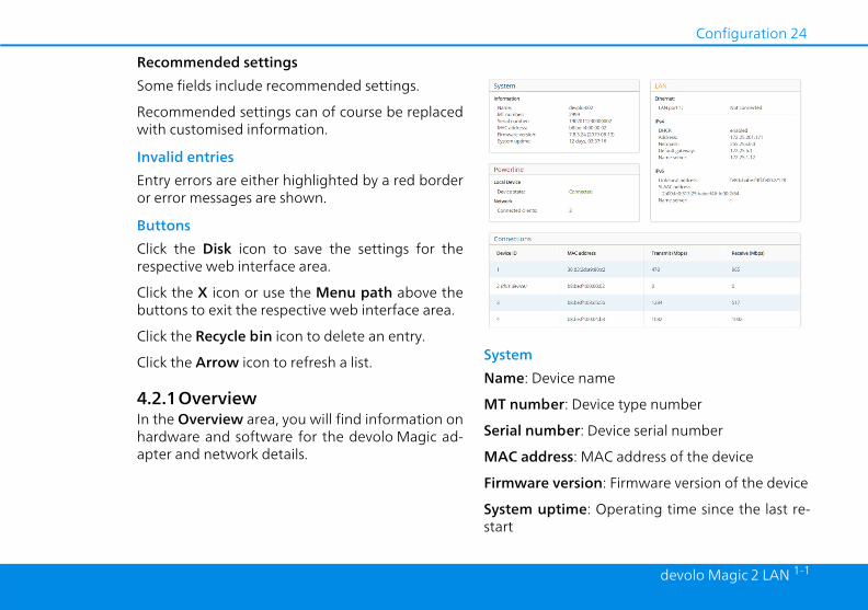
Recommended settings Some fields include recommended settings.
Recommended settings can of course be replacedwith customised information.
Invalid entriesEntry errors are either highlighted by a red borderor error messages are shown.
ButtonsClick the Disk icon to save the settings for therespective web interface area.
Click the X icon or use the Menu path above thebuttons to exit the respective web interface area.
Click the Recycle bin icon to delete an entry.
Click the Arrow icon to refresh a list.
4.2.1OverviewIn the Overview area, you will find information onhardware and software for the devolo Magic ad-apter and network details.
System Name: Device
MT number:
Serial numbe
MAC addres
Firmware ve
System uptimstart

25 Configuration
dev
lists all available and connected adapters for your network alongg the following details:
mber of the respective devolo Magice devolo Magic network
s: MAC address of the respective adapter
ps): Data transmission rate
ps): Data reception rate
find more detailed information on thed network details in Chapter 4.2.3
olo Magic 2 LAN 1-1
LAN – EthernetLAN port: network connection; if a connection hasbeen detected, the speed (10/100/1000 Mbps)and the mode (half/full duplex) are specified;otherwise, the status "unconnected" is specified.
LAN – IPv4 DHCP: Display indicating whether DHCP is swit-ched on or switched off
Address: IPv4 address in use
Netmask: IPv4 network mask in use
Default gateway: IPv4 gateway in use
Name server: DNSv4 server in use
LAN – IPv6Link-local address: Link-local address in use
SLAAC address: SLAAC address in use
Name server: DNSv6 server in use
PowerlineLocal device: Status information „connected“ or„not connected“
Network: Number of devices connected to thenetwork
ConnectionsThe table devolo Magicwith displayin
Device ID: nuadapter in th
MAC addresdevolo Magic
Transmit (Mb
Receive (Mb
You can displayeLAN.

Configuration 26
devolo Magic 2 LAN 1-1
devolo Cockpit or theme Network App (see Chapter 3.4n of devolo software), the PLC/reset button (see Chapter
ing and 3.3 Connecting theagic 2 LAN 1-1) web interface, in the Powerlineescribed below:
ng physical button and on-screen
ss the PLC/reset button on agic adapter in your existing network.
k Start pairing to start the pairing. This may take some time.
e new devolo Magic adapter is inte-our existing network, it appears in ale and established connections (seenections).
ng custom password assign your network a custom PLC pick yourself. Enter this password forMagic adapter in the Powerline
ld and confirm your entry with OK.
4.2.2PowerlineIn the Powerline area, you will find functions andinformation on the topic of Powerline and adapterpairing.
In order to use a new devolo Magic 2 LAN 1-1 inyour devolo Magic network, first you have toconnect it to your existing devolo Magic adaptersdevices as a network. This is accomplished by usinga shared password. This can be assigned in diffe-rent ways:
b Using devolo HoInstallatio
b Only using2.3 Pairdevolo M
b Using themenu; as d
Pairing – Usibutton
1 First, predevolo Ma
2 Then, clicoperation
As soon as thgrated into ylist of availabChapter Con
Pairing – UsiYou can alsopassword youeach devolopassword fie
27 Configuration
dev
de:
ission profiles:
r(default)
ch with your internet provider to find signal transmission profile is the best your internet connection.
perating mode and the VDSL 17a si-sion profile are configured by default.
olo Magic 2 LAN 1-1
Note that the custom password is not assignedto the whole PLC network automatically. In-stead, you must assign it separately to each ofyour devolo Magic adapters.
Powerline domain nameThe Powerline domain name determines the nameof your PLC network.
Unpairing – Resetting or removing an adapter from a network
1 To remove a devolo Magic adapter from yourdevolo Magic network, click Leave Powerlinenetwork.
2 Wait until the LED flashes red and then dis-connect the devolo Magic adapter from themains supply.
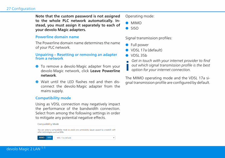
Compatibility modeUsing as VDSL connection may negatively impactthe performance of the bandwidth connection.Select from among the following settings in orderto mitigate any potential negative effects.
Operating mo
b MIMOb SISO
Signal transm
b Full poweb VDSL 17a b VDSL 35b
Get in touout whichoption for
The MIMO ognal transmis
Configuration 28
devolo Magic 2 LAN 1-1
server. The currently assigned net-isible (greyed out).
ver is already present on the networkt IP addresses (e.g. your Internet rou-ld enable the DHCP enabled optionevolo Magic 2 LAN 1-1 automaticallydress from it.
to assign a static IP address, makeingly for the Address, Subnetmask,
way and Name server fields.
settings by clicking the Disk icon.
the devolo Magic adapter (see Chap-oot) to ensure that your changes take
rationutomatic IP address assignment anddy a DHCP server present on the net-g out IP addresses (e.g. your Internet
le the DHCPv6 enabled option to en-devolo Magic 2 LAN 1-1 automatically
dress from this device.
to assign a static IP address, makedingly for the Address, Prefix, De-y and Name server fields.
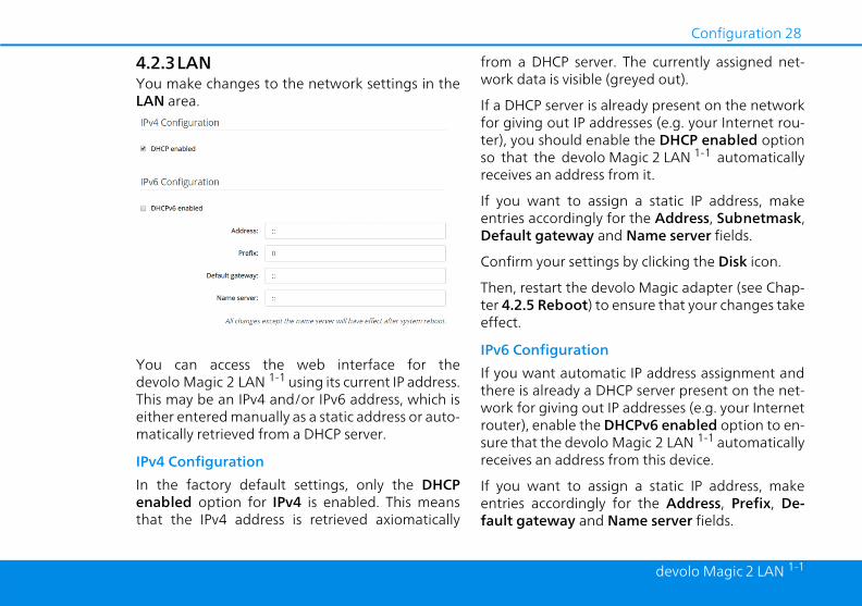
4.2.3LANYou make changes to the network settings in theLAN area.
You can access the web interface for thedevolo Magic 2 LAN 1-1 using its current IP address.This may be an IPv4 and/or IPv6 address, which iseither entered manually as a static address or auto-matically retrieved from a DHCP server.
IPv4 ConfigurationIn the factory default settings, only the DHCPenabled option for IPv4 is enabled. This meansthat the IPv4 address is retrieved axiomatically
from a DHCPwork data is v
If a DHCP serfor giving outer), you shouso that the dreceives an ad
If you want entries accordDefault gate
Confirm your
Then, restart ter 4.2.5 Rebeffect.
IPv6 ConfiguIf you want athere is alreawork for givinrouter), enabsure that the receives an ad
If you want entries accorfault gatewa

29 Configuration
dev
adapters are to be used and identi-twork.
login password for accessing the web
the built-in web interface of the2 LAN 1-1 is not protected by a
e recommend assigning a passwordallation of the devolo Magic 2 LAN 1-
to protect it against tampering by
olo Magic 2 LAN 1-1
Confirm your settings by clicking the Disk icon.
Then, restart the devolo Magic adapter (see Chap-ter 4.2.5 Reboot) to ensure that your changes takeeffect.
4.2.4SystemIn the System area, you can configure the settingsfor security and other devolo Magic adapter devicefunctions.
System InformationSystem information lets you enter an user-defi-ned name in the Device name (hostname) field.This information is particularly helpful if multiple
devolo Magicfied in the ne
Password.You can set ainterface.
By default, devolo Magicpassword. Wwhen the inst1 is completethird parties.

Configuration 30
devolo Magic 2 LAN 1-1
tting (see Chapter 2.3.1 Reading thet).
e mode has been enabled, the2 LAN 1-1 switches to Powersave
atically whenever reduced data trans-ethernet is detected.
ncy (time for transmitting a dataay be negatively affected.
mode is disabled in the2 LAN 1-1 factory default settings.
To do so, enter the desired new password twice.Now the web interface is protected against un-authorised access with your custom password!
Identify Device The devolo Magic adapter can be located using theIdentify device function. Click Identify to makethe white LED for the corresponding adapter flashfor 2 minutes to make it easier to identify by sight.
LEDEnable the LED disabled option if the LEDs on thedevolo Magic adapter are intended to be switchedoff for normal operation. An error status is indica-ted by corresponding flashing behaviour regard-
less of this seindicator ligh
PowersavingIf Powersavdevolo Magicmode autommission over
The latepacket) m
Powersave devolo Magic

31 Configuration
dev
evolo offers new versions on thefile download. The firmware updateted automatically or manually.
eck for firmware updatesagic 2 LAN 1-1 can look for up-to-
e automatically. To do this, enable thearly check for firmware updates.
agic 2 LAN 1-1 lets you know when ae version becomes available and asksould be updated.
ly install firmware updatesion Automatically install firmwarebled, the devolo Magic 2 LAN 1-1 au-stalls the firmware it has found.
olo Magic 2 LAN 1-1
StandbyIf Standby mode is enabled, thedevolo Magic 2 LAN 1-1 automatically switches toStandby mode if no ethernet connection has beenenabled, i.e. if no network device (e.g. computer) isswitched on and connected to the network inter-face and if Wi-Fi is disabled.
In this mode, the devolo Magic 2 LAN 1-1 is notaccessible over the Powerline network. As soon asthe network device (e.g. computer) connected tothe network interface is switched on again, youradapter can also be accessed over the electricalwiring again.
Standby mode is enabled in thedevolo Magic 2 LAN 1-1 factory default condition.
For information on the LED behaviour of thedevolo Magic adapter in standby mode, refer toChapter 2.3.1 Reading the indicator light.
Firmware updateThe currently installed firmware of thedevolo Magic adapter is displayed on the over-view page (see 4.2.1 Overview).
The firmware of the devolo Magic 2 LAN 1-1
includes the software for operating the device. If
necessary, dInternet as a can be initia
Regularly chThe devolo Mdate firmwaroption Regul
The devolo Mnew firmwarif firmware sh
AutomaticalWith the optupdates enatomatically in

Configuration 32
devolo Magic 2 LAN 1-1
evolo Magic adapter, click Reboot.
ngs
e a devolo Magic adapter from yourgic network and successfully restore
configuration to the factory defaultlick Factory reset.
the LED flashes white and then dis-he devolo Magic adapter from theply.
ind that all settings that have alreadye will be lost!
Manually initiate a firmware update 1 In order to manually update the firmware,
visit the devolo website (www.devolo.com).
1 Download the appropriate file for thedevolo Magic 2 LAN 1-1 to your computer.
2 Next, click on Browse for firmware file… andselect the downloaded firmware file.
3 Confirm your settings by clicking the disketteicon. After a successful update, thedevolo Magic 2 LAN 1-1 restarts automatically.
Ensure that the update procedure is notinterrupted.
4.2.5RebootHere, restart the devolo Magic adapter and/or re-store it to the factory default settings.
Reboot To restart a d
Factory Setti
1 To removdevolo Maits entire settings, c
2 Wait untilconnect tmains sup
Keep in mbeen mad

33 Appendix
dev
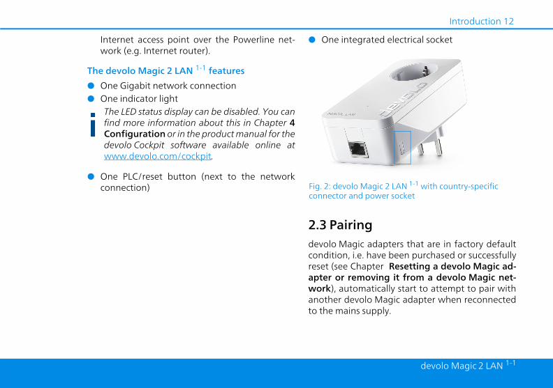
idth optimizationly improve the transmission capacityrk, we recommend that you complywing "connection rules":
evolo Magic 2 LAN 1-1 directly into at. Avoid using power strips. This may transmission of the PLC signals.e several sockets in the wall directlych other, they behave like a poweridual sockets are optimal.
ith optimization
olo Magic 2 LAN 1-1
5 Appendix
5.1 Technical specifications
5.2 BandwTo significantof the netwowith the follo
b Plug the dwall sockeimpair the
b If there arnext to eastrip. Indiv
Security 128 Bit AESDevice port 1x RJ45
(Gigabit Ethernet port)Power consumption Maximum: 4.8 W
Typical: 2.8 WStand-by: 0.7 W
Power supply internal196-250 V AC50 Hz
Temperature (Storage/Operating
-25°C to 70 °C / 0°C to40°C
Dimensions (in mm,without plug)
133x66x42 (HxWxD)
Ambient conditions 10-90% Humidity, non-condensing
Certifications CE
Fig. 3: Bandw

Appendix 34
devolo Magic 2 LAN 1-1
5.3 Disposal of old devicesTo be used in the countries of the European Unionand other European countries with a separate col-lecting system:
The icon with crossed-out wastebasket onthe device means that this product is anelectrical or electronic device that fallswithin the scope of application of the Eu-ropean Community WEEE Directive. The-se types of devices may no longer bedisposed of with household waste. Ratherthey can be given to a municipal collecti-on point free of charge. Contact your mu-nicipal government to find out theaddress and hours of the nearest collecti-on point.
5.4 Warranty conditionsIf your devolo device is found to be defective du-ring initial installation or within the warranty peri-od, please contact the vendor who sold you theproduct. The vendor will take care of the repair orwarranty claim for you. The complete warrantyconditions can be found at www.devolo.com/warranty.

devolo Magic 2 LAN 1-1
IndexAAdapter equipment 12CCE 8CE declaration 8Changing/assigning the network password 13, 20Ddevolo app 21devolo Cockpit 20devolo Magic 10devolo software 20DHCP server 28Disposal of old devices 34EExpanding an existing devolo Magic network 13FFactory default settings 13, 21Factory reset 13, 32IIntegrated electrical socket 17Intended use 7IP address 28IPv4 28LLAN (network connection) 17
LED status display 12, 14Login password 23NNetwork connection 17PPackage contents 18Pairing 12PLC 11, 12Powerline 11RReboot 32Reset 13, 21, 32Resetting a devolo Magic adapter 13SSafety notes 8Starting up a new devolo Magic network 13