Embed Size (px)
Citation preview

GUÍA DE INSTALACIÓN Y MANUAL DE USUARIO
SISTEMA DE MONITOREO REMOTO DE LA RED DE ACUEDUCTO DE LA CIUDADELA TERRANOVA
Versión 1.1 2009

2
INDICE
1.0. Requisitos ............................................................................................................................................... 3
2.0. Instalación .............................................................................................................................................. 4
2.1. Componentes requeridos ................................................................................................................... 4
2.2. Presupuesto ....................................................................................................................................... 5
2.3. Instalación de sensores ........................................................................................................................... 8
2.4. Instalación eléctrica de dispositivos de campo....................................................................................... 10
2.5. Instalación eléctrica de del centro de mando ........................................................................................ 10
2.6. Instalación de modem inalámbrico del centro de mando ....................................................................... 11
2.7. Instalación del modulo alambrado del centro de mando ....................................................................... 11
2.8. Instalación del modulo inalámbrico del sector B .................................................................................... 11
2.9. Instalación de cableado......................................................................................................................... 12
2.8.1. Conexión eléctrica de centro de mando ........................................................................................ 12
2.8.2. Conexión eléctrica de campo ........................................................................................................ 13
2.8.3. Conexión de sensores ................................................................................................................... 13
2.8.4. Conexión de comunicación serial .................................................................................................. 16
3.0. Configuración ....................................................................................................................................... 18
4.0. Uso ....................................................................................................................................................... 19
4.1. Componentes de la interfaz gráfica ................................................................................................... 19
4.2. Uso ................................................................................................................................................... 22
5.0. Solución de problemas .......................................................................................................................... 26

3
1.0. Requisitos
- Un computador con 512 MB de memoria RAM o superior, procesador x86 de 1 GHz o superior, disco duro de 20 GB o superior, tarjeta inalámbrica Ethernet 802.11g y un puerto serial RS-232 DB9.
- Sistema operativo Windows XP o superior. - Permisos de Administrador del sistema operativo.

4
2.0. Instalación
2.1. Componentes requeridos
Referencia Cantidad Base de datos MySQL versión 5.1 1 Servidor web Apache HTTP Server versión 2.2 1 Router inalámbrico 1 Computador con Windows XP o superior 1 Tarjeta Wireless Ethernet 802.11g 1 Conversor RS-232 a RS-485 1 Fuente de Alimentación Swicheada de 24 VDC @ 6,5 A 2 Modem RF B&B Electronics Zlinx Wireless Cod. ZZ24D-250RM-SR 1 Módulo I/O B&B Electronics Zlinx Wireless Cod. ZZ24D-NA-SR 1 Módulo I/O B&B Electronics Zlinx Wired 485 Cod. ZZ-NC-485 1 Módulo I/O de Expansión B&B Electronics Cod. ZZ-4AI 1 Transmisor de Presión Danfoss MBS3000-2011-1-AB08 5 Manómetro (0 - 200 PSI) 1 Bornera en línea de 9 pines 3 Bornera en línea de 6 pines 3 Tomacorriente 1 Luz Piloto 2 Breaker 10 A 2 Alambre 14 AWG 3 m Cable dúplex 16 AWG 60 m Caja en Acrílico Tipo 1 2 Caja en Acrílico Tipo 2 5 Caja de Lamina Galvanizada Tipo 1 1 Caja de Lamina Galvanizada Tipo 2 1 Caja de Lamina Galvanizada Tipo 3 1 Cable de Instrumentación Centelsa Cod. 201222 335 m Cable de Instrumentación Centelsa Cod. 201224 25 m Tubo PAVCO Conduit 3/4 Cod. 12478 240 m Caja Octagonal PAVCO Cod. 10590 5 Curvas 90º Conduit 3/4 PAVCO Cod. 11078 1 Uniones PAVCO Cod. 12856 80 Tubo PAVCO Presión 1/2 Cod. 12633 6 m Tee PAVCO 1/2 Cod. 12060 5 Tapon Roscado PAVCO 1/2 Cod. 11888 5 Llave de Paso Mariposa 1/2 5 Tubo metálico de 3’’ galvanizado 40

5
2.2. Presupuesto
Referencia Unidad Costo Unitario Cant. Costo Total
MySQL unitario $ 0,00 1 $ 0,00 Apache HTTP Server unitario $ 0,00 1 $ 0,00 Linksys Wireless-g Access Point Wap54g
unitario $ 180.000,00 1 $ 180.000,00 Computadora Lenovo M57e unitario $ 1.500.000,00 1 $ 1.500.000,00 Tarjeta PCI Encore Wireless unitario $ 50.000,00 1 $ 50.000,00 Conversor RS-232 a RS-485 unitario $ 200.000,00 1 $ 200.000,00 Fuente de Alimentación Swicheada de 24 VDC @ 6,5 A unitario $ 160.000,00 2 $ 320.000,00 Modem RF B&B Electronics Zlinx Wireless Cod. ZZ24D-250RM-SR unitario $ 479.600,00 1 $ 479.600,00 Módulo I/O B&B Electronics Zlinx Wireless Cod. ZZ24D-NA-SR unitario $ 913.000,00 1 $ 913.000,00 Módulo I/O B&B Electronics Zlinx Wired 485 Cod. ZZ-NC-485 unitario $ 547.800,00 1 $ 547.800,00 Módulo I/O de Expansión B&B Electronics Cod. ZZ-4AI unitario $ 657.800,00 1 $ 657.800,00 Transmisor de Presión Danfoss MBS3000-2011-1-AB08 unitario $ 542.300,00 5 $ 2.711.500,00 Manometro (0 - 200 PSI) unitario $ 40.000,00 1 $ 40.000,00 Bornera en Línea de 9 pines unitario $ 5.000,00 3 $ 15.000,00 Bornera en Línea de 6 pines unitario $ 4.000,00 3 $ 12.000,00 Resistencias de 100 Ω de 1/2 W unitario $ 50,00 5 $ 250,00 Tomacorriente unitario $ 2.000,00 1 $ 2.000,00 Breaker 10 A unitario $ 4.000,00 2 $ 8.000,00 Luz Piloto unitario $ 1.000,00 2 $ 2.000,00 Caja en Acrílico Tipo 1 unitario $ 60.000,00 2 $ 120.000,00 Caja en Acrílico Tipo 2 unitario $ 30.000,00 5 $ 150.000,00 Caja de Lamina Galvanizada Tipo 1 unitario $ 20.000,00 1 $ 20.000,00 Caja de Lamina Galvanizada Tipo 2 unitario $ 40.000,00 2 $ 80.000,00 Caja de Lamina Galvanizada Tipo 3 unitario $ 40.000,00 2 $ 80.000,00
Tubo Metálico de 3’’ Galvanizado metro $ 10.000,00 40 $ 400.000,00 Cable de Instrumentación Centelsa Cod. 201222
metro $ 3.329,00 335 $ 1.115.215,00 Cable de Instrumentación Centelsa Cod. 201224
metro $ 4.095,00 25 $ 102.375,00 Cable Dúplex 16 AWG metro $ 500,00 60 $ 30.000,00 Alambre 14 AWG metro $ 500,00 3 $ 1.500,00
6
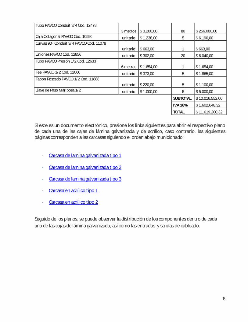
Tubo PAVCO Conduit 3/4 Cod. 12478 3 metros $ 3.200,00 80 $ 256.000,00
Caja Octagonal PAVCO Cod. 10590 unitario $ 1.238,00 5 $ 6.190,00 Curvas 90º Conduit 3/4 PAVCO Cod. 11078
unitario $ 663,00 1 $ 663,00 Uniones PAVCO Cod. 12856 unitario $ 302,00 20 $ 6.040,00 Tubo PAVCO Presión 1/2 Cod. 12633
6 metros $ 1.654,00 1 $ 1.654,00 Tee PAVCO 1/2 Cod. 12060 unitario $ 373,00 5 $ 1.865,00 Tapon Roscado PAVCO 1/2 Cod. 11888
unitario $ 220,00 5 $ 1.100,00 Llave de Paso Mariposa 1/2 unitario $ 1.000,00 5 $ 5.000,00
SUBTOTAL $ 10.016.552,00
IVA 16% $ 1.602.648,32
TOTAL $ 11.619.200,32
Si este es un documento electrónico, presione los links siguientes para abrir el respectivo plano de cada una de las cajas de lámina galvanizada y de acrílico, caso contrario, las siguientes páginas corresponden a las carcasas siguiendo el orden abajo municionado:
- Carcasa de lamina galvanizada tipo 1
- Carcasa de lamina galvanizada tipo 2
- Carcasa de lamina galvanizada tipo 3
- Carcasa en acrílico tipo 1
- Carcasa en acrílico tipo 2
Seguido de los planos, se puede observar la distribución de los componentes dentro de cada una de las cajas de lámina galvanizada, así como las entradas y salidas de cableado.

7
- Distribución espacial de los componentes dentro de la caja de lamina galvanizada tipo 1
- Distribución espacial de los componentes dentro de la caja de lamina galvanizada tipo 2

8
- Distribución espacial de los componentes dentro de la caja de lamina galvanizada tipo 3
2.3. Instalación de sensores
Se deben instalar 3 sensores de presión en el sector B ubicados de acuerdo a como se observa en la siguiente figura y también 2 sensores de presión en la planta, como se observar en la figura subsiguiente.
- Ubicación de los sensores de presión en el sector B

9
- Ubicación de los sensores en la planta
Para la instalación de los sensores, se debe realizar una reducción del tubo madre de la red de acueducto por medio de una T, reduciendo el diámetro de 6 o 3’’ de acuerdo a la ubicación del sensor en el sector o en la planta, a un diámetro de ½’’, instalando una llave mariposa de ½’’, seguida de una T, generándose una bifurcación, donde en un extremo se instala un tapón y en el otro extremo se instala el sensor de presión dentro de la carcasa de acrílico tipo 2.
- Diagrama de conexión del sensor a la red de acueducto
10
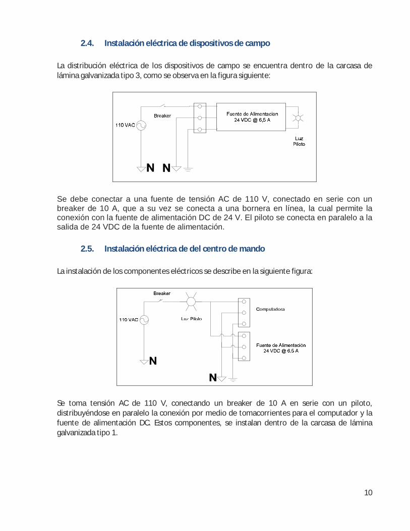
2.4. Instalación eléctrica de dispositivos de campo
La distribución eléctrica de los dispositivos de campo se encuentra dentro de la carcasa de lámina galvanizada tipo 3, como se observa en la figura siguiente:
Se debe conectar a una fuente de tensión AC de 110 V, conectado en serie con un breaker de 10 A, que a su vez se conecta a una bornera en línea, la cual permite la conexión con la fuente de alimentación DC de 24 V. El piloto se conecta en paralelo a la salida de 24 VDC de la fuente de alimentación.
2.5. Instalación eléctrica de del centro de mando
La instalación de los componentes eléctricos se describe en la siguiente figura:
Se toma tensión AC de 110 V, conectando un breaker de 10 A en serie con un piloto, distribuyéndose en paralelo la conexión por medio de tomacorrientes para el computador y la fuente de alimentación DC. Estos componentes, se instalan dentro de la carcasa de lámina galvanizada tipo 1.

11
2.6. Instalación de modem inalámbrico del centro de mando
El modem inalámbrico del centro de mando se debe posicionar a 20 metros de altura por medio de un tubo metálico galvanizado, instalado dentro de la carcasa en acrílico tipo 1. Se recomienda instalar el modem de acuerdo a la ubicación que se observa en la siguiente figura:
- Ubicación del modem inalámbrico en el centro de mando
2.7. Instalación del modulo alambrado del centro de mando
El modulo alambrado se debe instalar dentro de la carcasa de lamina galvanizada tipo 1, ubicándose a la izquierda de la carcasa, como se mostró anteriormente, localizando ésta carcasa dentro de las instalaciones de la planta.
2.8. Instalación del modulo inalámbrico del sector B
El modulo inalámbrico del sector B se debe ubicar de acuerdo al punto referenciado en la siguiente figura, elevándolo 20 metros, utilizando un tubo metálico galvanizado para ello. Se tiene que instalar dentro de la carcasa en acrílico tipo 1. La carcasa de lámina galvanizada tipo 3, la cual contiene la distribución eléctrica de campo se debe instalar en la parte inferior del tubo metálico mencionado en este párrafo.

12
- Ubicación del modulo inalámbrico de campo del sector B
2.9. Instalación de cableado
2.8.1. Conexión eléctrica de centro de mando
Para alimentar los dispositivos de campo, se debe conectar cada una de las borneras en el orden antes mencionado, mediante cable dúplex 16 AWG con la fuente de alimentación; luego, a la salida de las borneras que permiten al conexión con el modem inalámbrico, se debe conectar un cable dúplex 16 AWG llevándolo hasta éste dispositivo; y de la bornera de cada sensor, se debe conectar el hilo rojo del cable de instrumentación de 3 hilos a la bornera de 24 VDC y el hilo negro al común.

13
NOTA: Si se invierte la polaridad de los dispositivos o se conectan en los pines equivocados, es muy probable de que el dispositivo se dañe. Por lo tanto, tenga muy en cuenta como se conecta cada uno de los dispositivos para no afectar su funcionalidad.
2.8.2. Conexión eléctrica de campo
Se debe realizar la misma instalación con las mismas características del punto anterior, alimentando los dispositivos por medio de cable dúplex (para el módulo inalámbrico) y por medio de cable de instrumentación de 3 hilos (para los sensores).
NOTA: Al igual que el caso anterior, si se invierte la polaridad de los dispositivos o se conectan en los pines equivocados, es muy probable de que el dispositivo se dañe. Por lo tanto, tenga muy en cuenta como se conecta cada uno de los dispositivos para no afectar su funcionalidad.
2.8.3. Conexión de sensores
Como se observa en la siguiente figura, el sensor requiere alimentación de 24 VDC y un común, además de un hilo que transporta la señal de 4 – 20 mA, la cual se debe llevar hasta el módulo inalámbrico, antes pasando por una resistencia de 100 Ω en serie. El cableado utilizado es un cable de instrumentación de 3 hilos para todos los sensores.

14
Para la conexión de los sensores del centro de mando al modulo alambrado, se debe conectar por medio de un cable de instrumentación las borneras respectivas de cada sensor con la bornera de entrada análoga del módulo alambrado, como se observa en las siguientes figuras:
15
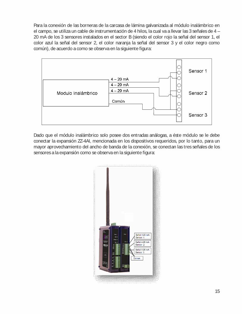
Para la conexión de las borneras de la carcasa de lámina galvanizada al módulo inalámbrico en el campo, se utiliza un cable de instrumentación de 4 hilos, la cual va a llevar las 3 señales de 4 – 20 mA de los 3 sensores instalados en el sector B (siendo el color rojo la señal del sensor 1, el color azul la señal del sensor 2, el color naranja la señal del sensor 3 y el color negro como común), de acuerdo a como se observa en la siguiente figura:
Dado que el módulo inalámbrico solo posee dos entradas análogas, a éste módulo se le debe conectar la expansión ZZ-4AI, mencionada en los dispositivos requeridos, por lo tanto, para un mayor aprovechamiento del ancho de banda de la conexión, se conectan las tres señales de los sensores a la expansión como se observa en la siguiente figura:
16
NOTA: Para evitar daño en el modulo inalámbrico, se deben conectar las entradas como se muestra en la figura anterior, si se invierte las polaridades no solo se obtienen datos incorrectos sino que se corre con el riesgo de dañar el dispositivo.
NOTA: Para un mayor aprovechamiento del ancho de banda, si solo hay dos señales análogas, se deben conectar al módulo base (ya sea alambrado o inalámbrico), si hay entre 3 y 4 señales se deben conectar todas estas en una expansión y si hay más de 4 señales, se debe empezar a conectar desde el modulo base y siguiendo con las expansiones. Si no se tiene en cuenta este enunciado y se realiza una conexión incorrecta, el sistema funcionará de manera inadecuada.
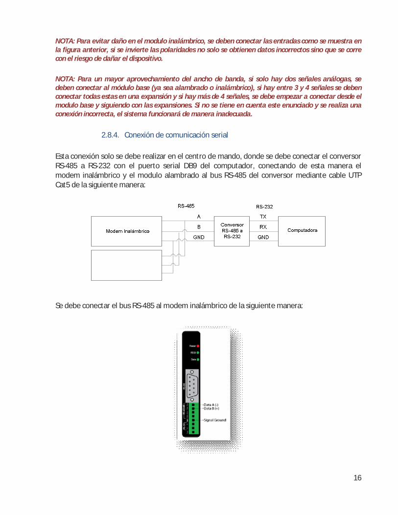
2.8.4. Conexión de comunicación serial
Esta conexión solo se debe realizar en el centro de mando, donde se debe conectar el conversor RS-485 a RS-232 con el puerto serial DB9 del computador, conectando de esta manera el modem inalámbrico y el modulo alambrado al bus RS-485 del conversor mediante cable UTP Cat5 de la siguiente manera:
Se debe conectar el bus RS-485 al modem inalámbrico de la siguiente manera:

17
Y se debe conectar el modulo inalambrico al bus RS-485 de la siguiente manera:
NOTA: Si se invierte el orden de los pines para la conexión al bus RS-485, no se va a generar la comunicación, por lo tanto, el sistema nunca va a poder funcionar, además de que se pueden afectar seriamente los dispositivos.

18
3.0. Configuración
Para la configuración del modem inalámbrico, referirse al manual “ZPxxD-xxxZ-MR-2508m.pdf”, de la página 12 a la 15; para la configuración del modulo alambrado, referirse al manual “Zlinx485m-1808.pdf” de las página 24 a la 30 (teniendo en cuenta que se debe configurar como modo Modbus en la dirección 64) y para la configuración del modulo inalámbrico, referirse al manual “ZlinxWirelessModbusIO-1909ds.pdf” de las páginas 35 a la 42 (se debe configurar también en modo Modbus con la dirección 66).
Se deben configurar los módulos antes de ser instalados, ya que requieren estar conectados físicamente con el computador mediante un cable de datos serial RS-232. Luego se puede realizar la instalación antes mencionada.
Todos los módulos se deben configurar con un Baud rate de 9600 bps, sin bit de paridad (Parity = None) y un único bit de parada (Stop Bit = 1).

19
4.0. Uso
4.1. Componentes de la interfaz gráfica
Para poner en funcionamiento el sistema, se debe abrir el programa “MonitoreoRemoto.exe” ubicado en la carpeta “Sistema de Monitoreo”. Una vez abierto, se debe visualiza la siguiente interfaz:
En esta interfaz se puede visualizar toda la información relacionada con la red de acueducto de la ciudadela Terranova, discriminando la información mediante el uso de pestañas, donde cada pestaña representa la información de cada sector, por lo tanto, la seleccionar la pestaña de un sector solo se va a obtener los datos obtenidos de este sector; en caso de querer visualizar los datos de todos los sectores en una única ventana, se debe seleccionar la pestaña “Global”, donde se visualiza en modo texto la información respectiva de todos los sectores.
20
NOTA: Esta versión solo tiene habilitado la adquisición, visualización y almacenamiento del Sector B y la Planta.
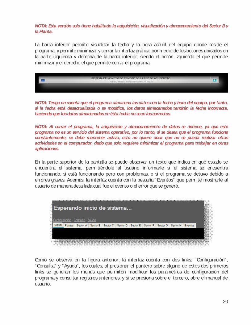
La barra inferior permite visualizar la fecha y la hora actual del equipo donde reside el programa, y permite minimizar y cerrar la interfaz gráfica, por medio de los botones ubicados en la parte izquierda y derecha de la barra inferior, siendo el botón izquierdo el que permite minimizar y el derecho el que permite cerrar el programa.
NOTA: Tenga en cuenta que el programa almacena los datos con la fecha y hora del equipo, por tanto, si la fecha está desactualizada o se modifica, los datos almacenados tendrán la fecha incorrecta, haciendo que los datos almacenados en ésta fecha no sean los correctos.
NOTA: Al cerrar el programa, la adquisición y almacenamiento de datos se detiene, ya que este programa no es un servicio del sistema operativo, por lo tanto, si se desea que el programa funcione constantemente, se debe mantener activo, esto no quiere decir que no se pueda realizar otras actividades en el computador, dado que solo requiere minimizar el programa para trabajar en otras aplicaciones.
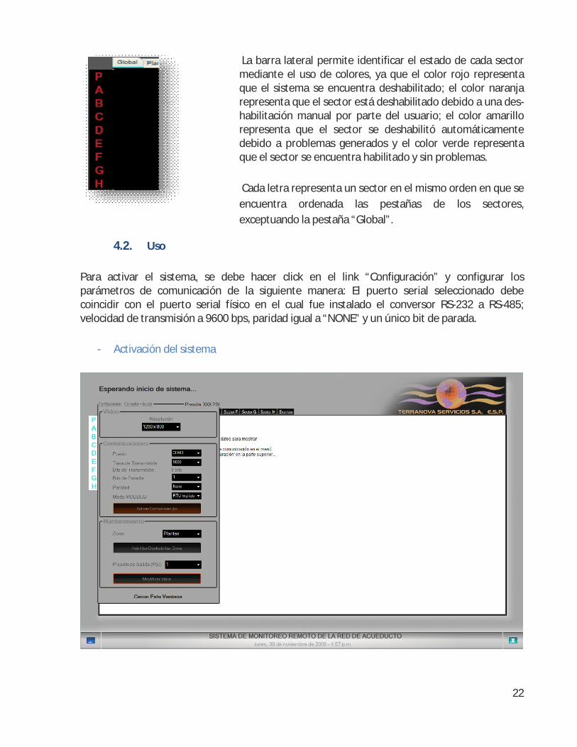
En la parte superior de la pantalla se puede observar un texto que indica en qué estado se encuentra el sistema, permitiéndole al usuario informarle si el sistema se encuentra funcionando, si está funcionando pero con problemas, o si el programa se detuvo debido a errores graves. Además, la interfaz cuenta con la pestaña “Eventos” que permite mostrarle al usuario de manera detallada cual fue el evento o el error que se generó.
Como se observa en la figura anterior, la interfaz cuenta con dos links: “Configuración”, “Consulta” y “Ayuda”, los cuales, al presionar el puntero sobre alguno de estos dos primeros links se generan los menús que permiten modificar los parámetros de configuración del programa y consultar registros anteriores, y si se presiona sobre el tercero, abre el manual de usuario.

21
Como se observa en ésta figura, al hacer click sobre el link “Configuración”, se visualiza un menú que permite el cambio de la resolución de la aplicación, ya que esta aplicación se desarrollo teniendo en cuenta que se iba a ocupar la totalidad de la pantalla para una mejor visualización de acuerdo al tipo de monitor que se utilice. Además, el menú cuenta con un sub-menú que permite la configuración del sistema, dado que permite configurar los parámetros necesarios para conectarse con todos los módulos inalámbricos instalados en cada uno de los sectores; por medio del botón en este sub-menú se activa o se desactiva la comunicación, activando y desactivando de esta manera la adquisición y almacenamiento del sistema. Por último, se cuenta con otro sub-menú, el cual permite seleccionar un sector, y presionando el botón “Habilitar/Deshabilitar Zona” se puede habilitar o deshabilitar este sector, incluso mientras el sistema se encuentra en funcionamiento; habilitando de ésta manera que pueda realizar algún tipo de mantenimiento en el sector seleccionado.
NOTA: En caso de realizarse algún mantenimiento en algún sector, se debe deshabilitar, ya que se genera un comportamiento indebido de la red de acueducto, generando de ésta manera las alarmas respectivas. Además, si se realiza algún tipo de mantenimiento en algún sector sin deshabilitar el mismo, puede suceder que se almacenen datos no validos que no están acordes a la realidad de la situación.
Al presionar el link de “Consulta”, se despliega el menú de la figura lateral, el cual permite realizar consultas en los datos almacenados, discriminando los datos en cuanto a la fecha seleccionada y en qué sector o zona se debe buscar. Al presionar el botón “Generar consulta”, se abre otra ventana con los datos encontrados. Si desea que solo se visualice en las grafos determinados parámetros, solamente deselecciónelos.
NOTA: Se pueden realizar múltiples consultas al mismo tiempo, solo se debe realizar la consulta y la
aplicación abre otra ventana a las existentes con los datos encontrados.
NOTA: Si no hay registros de la fecha seleccionada en el sector seleccionado, se genera un cuadro de texto advirtiendo esta situación. Además, si se consulta un sector que no ha sido implementado, también se genera un cuadro de texto advirtiendo éste error.
22
La barra lateral permite identificar el estado de cada sector mediante el uso de colores, ya que el color rojo representa que el sistema se encuentra deshabilitado; el color naranja representa que el sector está deshabilitado debido a una des-habilitación manual por parte del usuario; el color amarillo representa que el sector se deshabilitó automáticamente debido a problemas generados y el color verde representa que el sector se encuentra habilitado y sin problemas.
Cada letra representa un sector en el mismo orden en que se encuentra ordenada las pestañas de los sectores, exceptuando la pestaña “Global”.
4.2. Uso
Para activar el sistema, se debe hacer click en el link “Configuración” y configurar los parámetros de comunicación de la siguiente manera: El puerto serial seleccionado debe coincidir con el puerto serial físico en el cual fue instalado el conversor RS-232 a RS-485; velocidad de transmisión a 9600 bps, paridad igual a “NONE” y un único bit de parada.
- Activación del sistema

23
Luego hacer click en el botón “Habilitar comunicación”, luego se debe esperar a que el sistema reciba los datos de cada uno de los módulos instalados, y al recibirlos estarán disponibles para el usuario.
En la pestaña “Global” se observa los datos adquiridos en modo texto como se observa en la siguiente figura:
- Modo “Global”
Y si selecciona alguna pestaña de los sectores, se visualiza el mapa de la red de acueducto, y pasando el puntero sobre los puntos donde se encuentran instalados los sensores, se despliega un cuadro informativo con la información de este punto de sensado.

24
- Modo por sector
Para deshabilitar el sistema, solamente se debe hacer click sobre el link “Configuración” y hacer click sobre el botón “Deshabilitar comunicación”. Las consultas a la base de datos se pueden realizar estando el sistema activado o desactivado, el único requerimiento necesario es tener la base de datos MySQL activada. La consulta se realiza ingresando la fecha del día a consultar, seleccionar la zona que se requiere y seleccionar o deseleccionar los parámetros que desean ser visualizados (set-point, promedio, máximos y mínimos). Al realizar la consulta se obtienen los tabulados de los datos solicitados, así como los grafos respectivos a éstos datos, donde se discrimina por punto de sensado y del sector, como se observa en la siguiente figura:

25
Se pueden realizar consultas simultaneas, no se requiere cerrar las ventanas de la consulta actual para poder realizar una nueva consulta; esto con el fin de poder comparar diversos días simultáneamente.

26
5.0. Solución de problemas
5.1. La aplicación de monitoreo constantemente genera un error debido a que se
presentan presiones negativas en uno o varios puntos de sensado.
Esto se debe a que el sensor(es) mencionado(s) no se encuentra conectado con los módulos de adquisición de datos. Verifique que el sensor se encuentre alimentado, así como verificar el estado de los cables de instrumentación y la conexión entre el sensor y el módulo de adquisición de datos. Si el problema persiste, probablemente el sensor este dañado.
5.2. La aplicación de monitoreo constantemente genera un error debido a presiones superiores a 145 PSI en uno o varios puntos de sensado.
Esto se debe a sobre-presiones en la red o que haya fuentes de ruido que afectan la conexión entre el sensor y el módulo de adquisición de datos.
5.3. La aplicación de monitoreo constantemente genera un error debido a que hubo una función MODBUS no habilitada.
Si este error se genera muy seguido, probablemente se tenga una interferencia en el bus de datos RS-485 o una interferencia en el envió de datos de manera inalámbrica que corrompen los datos. Verifique que no existan focos electromagnéticos como transformadores de alta tensión cerca de los módulos inalámbricos.
5.4. La aplicación de monitoreo constantemente genera un error debido a que se solicitaron memorias a los módulos no validas.
Este error se genera cuando existe una entrada análoga defectuosa o no se conectó de manera correcta la expansión a los módulos de adquisición de datos, ignorando las entradas de éste dispositivo. Verifique la conexión de los módulos de expansión con los módulos de adquisición de datos; si el problema continúa, puede que se haya averiado el módulo de adquisición de datos.
5.5. La aplicación de monitoreo constantemente genera un error debido a que el CRC no fue satisfactorio o que llegaron datos corruptos.
Si constantemente se genera este error, verifique la conexión del bus RS-485, dado que éste problema se genera cuando hay fuentes electromagnéticas que afectan la conexión; además, verifique también si existen focos electromagnéticos cerca de los módulos inalámbricos que puedan afectar esta comunicación.

27
5.6. No se puede generar el enlace entre el módulo alambrado y la aplicación de monitoreo.
Verifique que las conexiones entre los dispositivos estén en buen estado y sean correctas, así como también el estado del cable. Además, verifique que se haya conectado en el puerto serial seleccionado en la aplicación de monitoreo con los parámetros velocidad de transmisión en 9600, sin paridad y un solo bit de stop. Si todavía no se genera la conexión, verifique que los módulos tengan la dirección MODBUS correctas (64 para el módulo alambrado de la planta y 66 para el módulo inalámbrico del sector B).
Si después de realizar todo lo anterior no se genera la conexión, verifique que el firewall del computador permita habilitar el puerto serial, así como también se debe verificar que la aplicación posea derechos administrativos para utilizar este puerto. Si aún no se puede generar la conexión verifique si funcionan tanto el puerto serial del computador como del módulo, dado que pueden estar dañados.
5.7. Existía un enlace entre el módulo alambrado y el computador, pero ya no funciona.
Verifique el estado de las conexiones, así como del cable de comunicación. Verifique también el funcionamiento de cada uno de los puertos seriales de los dispositivos de manera individual para verificar que no hayan averías, y si recientemente se hizo cambios de software (como antivirus o firewalls) o se reinstaló de nuevo el sistema operativo, verifique la aplicación tengan los permisos respectivos para utilizar el puerto serial.
5.8. Se genera el siguiente error “Unable to connect MySQL to any host”
Este error se genera cuando la base de datos no se encuentra activa. Vaya al menú “Inicio” y luego al menú “Accesorios” y abra el símbolo del sistema y copie la siguiente línea “mysqld -start”, esto activa la base de datos (puede cerrar el símbolo del sistema luego de activar la base de datos).
5.9. No se puede abrir la página web, el explorador web no puede encontrarla.
Puede que el equipo se haya apagado y al inicializarse de nuevo no cargó el servidor web. En este caso, diríjase al menú “Inicio” de Windows, luego a “Todos los programas” y Seleccionar “Apache HTTP Server 2.2”, presionar en “Monitor Apache Server”, y en el área de notificación de Windows (junto al reloj), debe aparecer un ícono como el siguiente:

28
Si el ícono visualizado no es como el anterior, sino que en vez de una flecha verde dentro del círculo blanco tiene un cuadro rojo o éste ícono ya estaba en el área de notificación pero con el cuadro rojo dentro del círculo blanco, de click izquierdo sobre éste ícono, abra el menú y luego seleccione “Stop”, seguido, realice el mismo procedimiento anterior pero seleccionando “Start”. Luego de esto el ícono debe tomar la forma de la figura anterior siendo posible abrir la página web.
Si el problema persiste, asegúrese que el computador se encuentre conectado y activo dentro de la red LAN de la empresa y tenga los permisos para conectarse a ésta.
5.10. Cuando se intenta abrir la aplicación de monitoreo, se bloquea y Windows lo cierra.
Este error se genera cuando no se ha instalado el paquete .NET Framework 3.5. Para solucionarlo, vaya a la página web de Microsoft (link: http://msdn.microsoft.com/en-us/netframework/default.aspx), descargue e instale este paquete en el computador.

29
Desarrollado por: Carlos F. Londoño
Ingeniero Electrónico Jorge E. Aponte
Ingeniero Electrónico
2009

Manual Documentation Number: ZPXXx-XXXXx-MR-2508 1 B&B Electronics Mfg Co Inc – 707 Dayton Rd - PO Box 1040 - Ottawa IL 61350 - Ph 815-433-5100 - Fax 815-433-5104 – www.bb-elec.com
B&B Electronics – Westlink Commercial Park – Oranmore, Galway, Ireland – Ph +353 91-792444 – Fax +353 91-792445 – www.bb-europe.com
Zlinx Radio Modem
ZP Series Documentation Number: ZPXXx-XXXXx-MR-2508
pn#7696R1
This product designed and manufactured in Ottawa, Illinois USA
of domestic and imported parts by
707 Dayton Road -- P.O. Box 1040 -- Ottawa, IL 61350 USA Phone (815) 433-5100 -- General Fax (815) 433-5105
Phone (815) 433-5100 -- General Fax (815) 433-5105
Website: www.bb-elec.com
European Headquarters
B&B Electronics
Westlink Commercial Park -- Oranmore, Co. Galway, Ireland
Phone +353 91-792444 -- Fax +353 91-792445 Website: www.bb-europe.com
B&B Electronics Mfg. Co. Inc. – June 2008

2 Manual Documentation Number: ZPXXx-XXXXx-XR-2508 B&B Electronics Mfg Co Inc – 707 Dayton Rd - PO Box 1040 - Ottawa IL 61350 - Ph 815-433-5100 - Fax 815-433-5104 – www.bb-elec.com
B&B Electronics – Westlink Commercial Park – Oranmore, Galway, Ireland – Ph +353 91-792444 – Fax +353 91-792445 – www.bb-europe.com
This document contains information that is proprietary and confidential to B&B Electronics Mfg. Co. Inc. The methods described herein are for the exclusive use of B&B Electronics authorized personnel. Any unauthorized use or dissemination of the information contained in the document is strictly forbidden.

Manual Documentation Number: ZPXXx-XXXXx-MR-2508 3 B&B Electronics Mfg Co Inc – 707 Dayton Rd - PO Box 1040 - Ottawa IL 61350 - Ph 815-433-5100 - Fax 815-433-5104 – www.bb-elec.com
B&B Electronics – Westlink Commercial Park – Oranmore, Galway, Ireland – Ph +353 91-792444 – Fax +353 91-792445 – www.bb-europe.com
Table of Contents
Introduction 4
PACKAGE CONTENTS 4
Hardware Installation 5
DIP SWITCH SETTINGS 5 MOUNTING AND POWER 5 SERIAL CONNECTIONS 6 RS-232 6 RS-422/485 7 WIRELESS LINK FAILURE OUTPUT 8 LED INDICATORS 9 RADIO FREQUENCY INFORMATION 9
Zlinx Manager Software 11
INSTALLATION 11 SET UP 11 ON-LINE CONFIGURATION 13 TEST / TROUBLESHOOT 17 FIRMWARE UPDATE 19
Specifications 20
Advanced Programming 23
BINARY COMMAND EXAMPLE 24 COMMAND REFERENCE TABLE 25 ZLINX COMMAND DESCRIPTIONS 29

4 Manual Documentation Number: ZPXXx-XXXXx-XR-2508 B&B Electronics Mfg Co Inc – 707 Dayton Rd - PO Box 1040 - Ottawa IL 61350 - Ph 815-433-5100 - Fax 815-433-5104 – www.bb-elec.com
B&B Electronics – Westlink Commercial Park – Oranmore, Galway, Ireland – Ph +353 91-792444 – Fax +353 91-792445 – www.bb-europe.com
Introduction Easy to install, up to 7 mile range No wires, no cables! Zlinx radio modems get your data moving farther, easier, and at less cost than running cable. Plug-n-play, Modbus compatible, signal strength indicator, space saving DIN rail mounting. Heavy-duty, wide temperature design handles most industrial power configurations and tough indoor/outdoor environments.
Package Contents • Radio Modem (Table Above) • Antenna • Software CD • Manual on CD • Will require separate 18-30VAC or 10-48VDC Power Supply
ZP24D-xxxx-MR = 1.5W max ZP9D-xxxx-MR = 1.5W max
Model # Frequency Radio Power
RF Data Rate
ZP24D-192RM-MR 2.4GHz 50mW 19.2Kbps ZP24D-96RM-MR 2.4GHz 50mW 9600bps ZP9D-192RM-MR 900MHz 100mW 19.2Kbps ZP9D-96RM-MR 900MHz 100mW 9600bps
Manual Documentation Number: ZPXXx-XXXXx-MR-2508 5 B&B Electronics Mfg Co Inc – 707 Dayton Rd - PO Box 1040 - Ottawa IL 61350 - Ph 815-433-5100 - Fax 815-433-5104 – www.bb-elec.com
B&B Electronics – Westlink Commercial Park – Oranmore, Galway, Ireland – Ph +353 91-792444 – Fax +353 91-792445 – www.bb-europe.com
Hardware Installation
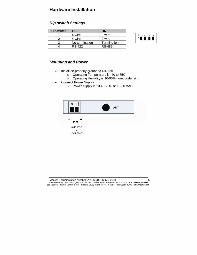
Dip switch Settings
Dipswitch OFF ON 1 4-wire 2-wire 2 4-wire 2-wire 3 No termination Termination 4 RS-422 RS-485
Mounting and Power
• Install on properly grounded DIN rail o Operating Temperature is -40 to 85C o Operating Humidity is 10-90% non-condensing
• Connect Power Supply o Power supply is 10-48 VDC or 18-30 VAC
10-48 VDC or
18-30 VAC

6 Manual Documentation Number: ZPXXx-XXXXx-XR-2508 B&B Electronics Mfg Co Inc – 707 Dayton Rd - PO Box 1040 - Ottawa IL 61350 - Ph 815-433-5100 - Fax 815-433-5104 – www.bb-elec.com
B&B Electronics – Westlink Commercial Park – Oranmore, Galway, Ireland – Ph +353 91-792444 – Fax +353 91-792445 – www.bb-europe.com
RS-232
Serial Connections
RS-232 RS-232 always present on DB9
DB9F Pin Signal Name Direction1 Data Carrier Detect Out 2 Receive Data Out 3 Transmit Data In 4 Data Terminal Ready In 5 Signal Ground --- 6 Data Set Ready Out 7 Request To Send In 8 Clear To Send Out 9 Not used ---
Note: The DTR input is used to put the radio into sleep mode. The radio sleep option must be enabled first using the configuration software. Once enabled, lowering the DTR signal will put the radio in sleep mode and raising the DTR signal will put the radio in idle mode, ready to receive or transmit data.

Manual Documentation Number: ZPXXx-XXXXx-MR-2508 7 B&B Electronics Mfg Co Inc – 707 Dayton Rd - PO Box 1040 - Ottawa IL 61350 - Ph 815-433-5100 - Fax 815-433-5104 – www.bb-elec.com
B&B Electronics – Westlink Commercial Park – Oranmore, Galway, Ireland – Ph +353 91-792444 – Fax +353 91-792445 – www.bb-europe.com
RS-485 (2-Wrie) RS-422/485 (4-Wire)
RS-422/485
8 Manual Documentation Number: ZPXXx-XXXXx-XR-2508 B&B Electronics Mfg Co Inc – 707 Dayton Rd - PO Box 1040 - Ottawa IL 61350 - Ph 815-433-5100 - Fax 815-433-5104 – www.bb-elec.com
B&B Electronics – Westlink Commercial Park – Oranmore, Galway, Ireland – Ph +353 91-792444 – Fax +353 91-792445 – www.bb-europe.com
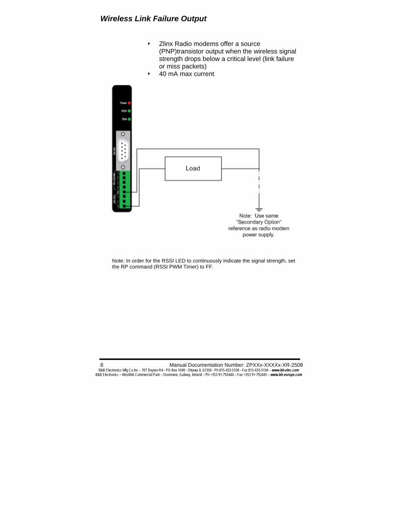
Wireless Link Failure Output
Zlinx Radio modems offer a source (PNP)transistor output when the wireless signal strength drops below a critical level (link failure or miss packets)
40 mA max current
Note: In order for the RSSI LED to continuously indicate the signal strength, set the RP command (RSSI PWM Timer) to FF.

Manual Documentation Number: ZPXXx-XXXXx-MR-2508 9 B&B Electronics Mfg Co Inc – 707 Dayton Rd - PO Box 1040 - Ottawa IL 61350 - Ph 815-433-5100 - Fax 815-433-5104 – www.bb-elec.com
B&B Electronics – Westlink Commercial Park – Oranmore, Galway, Ireland – Ph +353 91-792444 – Fax +353 91-792445 – www.bb-europe.com
LED Indicators
Note: In order for the RSSI LED to continuously indicate the signal strength, set the RP command (RSSI PWM Timer) to FF.
Radio Frequency Information • The Zlinx Product is shipped with an antenna with the
following expected ranges. o These ranges are for line of sight installations and
may vary depending on your particular installation. o The antenna connection on the radio modem is an
RPSMA female plug. o B&B Electronics has a wide variety of accessory
antennas. Visit www.bb-elec.com.
Front Panel LED Status Power Red = ON
OFF = No Power RSSI (Signal Strength) Green = Strong
Yellow = OK Red = Weak OFF = No Signal
Wireless Data Green = Blink ON with data
Model # Indoor Range
Outdoor Range
ZP24D-192RM-MR up to 600 feet
up to 3 miles
ZP24D-96RM-MR up to 600 feet
up to 3 miles
ZP9D-192RM-MR up to 1500 feet
up to 7 miles
ZP9D-96RM-MR up to 1500 feet
up to 7 miles

10 Manual Documentation Number: ZPXXx-XXXXx-XR-2508 B&B Electronics Mfg Co Inc – 707 Dayton Rd - PO Box 1040 - Ottawa IL 61350 - Ph 815-433-5100 - Fax 815-433-5104 – www.bb-elec.com
B&B Electronics – Westlink Commercial Park – Oranmore, Galway, Ireland – Ph +353 91-792444 – Fax +353 91-792445 – www.bb-europe.com
• The radio frequency, power, and data rate vary depending
on model. Refer to the table below.
Model # Frequency Radio Power
RF Data Rate
ZP24D-192RM-MR 2.4GHz 50mW 19.2Kbps ZP24D-96RM-MR 2.4GHz 50mW 9600bps ZP9D-192RM-MR 900MHz 100mW 19.2Kbps ZP9D-96RM-MR 900MHz 100mW 9600bps
Manual Documentation Number: ZPXXx-XXXXx-MR-2508 11 B&B Electronics Mfg Co Inc – 707 Dayton Rd - PO Box 1040 - Ottawa IL 61350 - Ph 815-433-5100 - Fax 815-433-5104 – www.bb-elec.com
B&B Electronics – Westlink Commercial Park – Oranmore, Galway, Ireland – Ph +353 91-792444 – Fax +353 91-792445 – www.bb-europe.com
Zlinx Manager Software
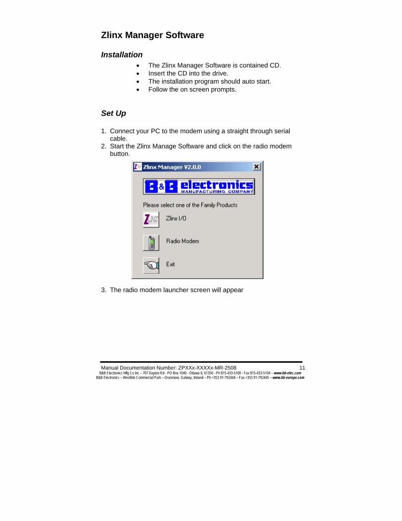
Installation • The Zlinx Manager Software is contained CD. • Insert the CD into the drive. • The installation program should auto start. • Follow the on screen prompts.
Set Up 1. Connect your PC to the modem using a straight through serial
cable. 2. Start the Zlinx Manage Software and click on the radio modem
button.
3. The radio modem launcher screen will appear

12 Manual Documentation Number: ZPXXx-XXXXx-XR-2508 B&B Electronics Mfg Co Inc – 707 Dayton Rd - PO Box 1040 - Ottawa IL 61350 - Ph 815-433-5100 - Fax 815-433-5104 – www.bb-elec.com
B&B Electronics – Westlink Commercial Park – Oranmore, Galway, Ireland – Ph +353 91-792444 – Fax +353 91-792445 – www.bb-europe.com
3. Click on the Radio Modem Configuration button to configure the modem on-line or the Radio Modem Configuration Button (offline) to configure the modem offline. Follow the on screen directions to configure the modem. Note: using the off-line configuration button skips the auto modem discovery process.

Manual Documentation Number: ZPXXx-XXXXx-MR-2508 13 B&B Electronics Mfg Co Inc – 707 Dayton Rd - PO Box 1040 - Ottawa IL 61350 - Ph 815-433-5100 - Fax 815-433-5104 – www.bb-elec.com
B&B Electronics – Westlink Commercial Park – Oranmore, Galway, Ireland – Ph +353 91-792444 – Fax +353 91-792445 – www.bb-europe.com
On-Line Configuration 1. Click the Radio Modem Configuration Button. The following screen will appear.
2. Use the pull down menu items to set up the communication parameters.
14 Manual Documentation Number: ZPXXx-XXXXx-XR-2508 B&B Electronics Mfg Co Inc – 707 Dayton Rd - PO Box 1040 - Ottawa IL 61350 - Ph 815-433-5100 - Fax 815-433-5104 – www.bb-elec.com
B&B Electronics – Westlink Commercial Park – Oranmore, Galway, Ireland – Ph +353 91-792444 – Fax +353 91-792445 – www.bb-europe.com
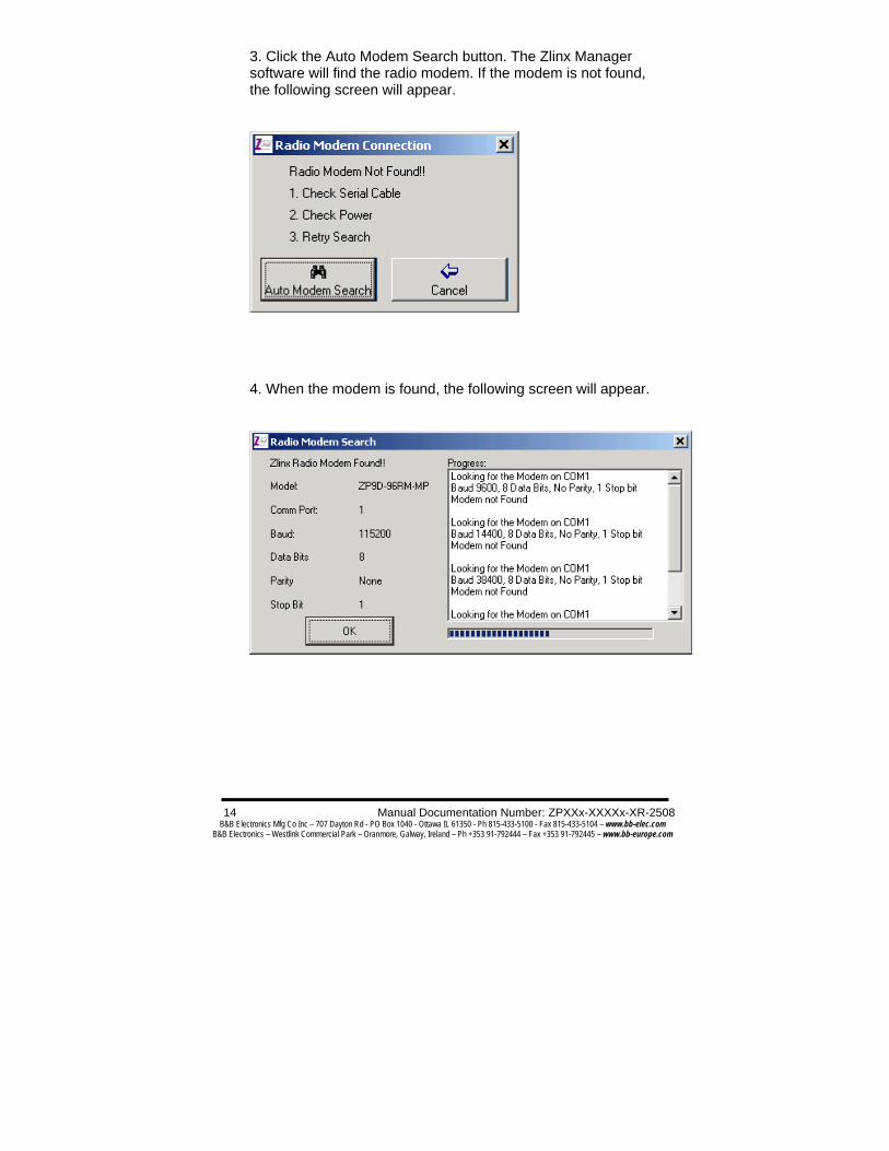
3. Click the Auto Modem Search button. The Zlinx Manager software will find the radio modem. If the modem is not found, the following screen will appear.
4. When the modem is found, the following screen will appear.

Manual Documentation Number: ZPXXx-XXXXx-MR-2508 15 B&B Electronics Mfg Co Inc – 707 Dayton Rd - PO Box 1040 - Ottawa IL 61350 - Ph 815-433-5100 - Fax 815-433-5104 – www.bb-elec.com
B&B Electronics – Westlink Commercial Park – Oranmore, Galway, Ireland – Ph +353 91-792444 – Fax +353 91-792445 – www.bb-europe.com
5. Click OK. The following screen will appear.

16 Manual Documentation Number: ZPXXx-XXXXx-XR-2508 B&B Electronics Mfg Co Inc – 707 Dayton Rd - PO Box 1040 - Ottawa IL 61350 - Ph 815-433-5100 - Fax 815-433-5104 – www.bb-elec.com
B&B Electronics – Westlink Commercial Park – Oranmore, Galway, Ireland – Ph +353 91-792444 – Fax +353 91-792445 – www.bb-europe.com
5. On the Basic Modem setting tab, configure a unique channel number, network identifier, and destination address. This will prevent interference from other modems. Click the Update button to save the parameters. Click the Restore Defaults button to revert to the default configuration. 6. Use the advanced tab to configure additional parameters. When each option is highlighted, the text box will display an explanation of the command and the associated hex range. Click the update button to save the parameters. Click the Restore Defaults button to revert to the default configuration.
Manual Documentation Number: ZPXXx-XXXXx-MR-2508 17 B&B Electronics Mfg Co Inc – 707 Dayton Rd - PO Box 1040 - Ottawa IL 61350 - Ph 815-433-5100 - Fax 815-433-5104 – www.bb-elec.com
B&B Electronics – Westlink Commercial Park – Oranmore, Galway, Ireland – Ph +353 91-792444 – Fax +353 91-792445 – www.bb-europe.com
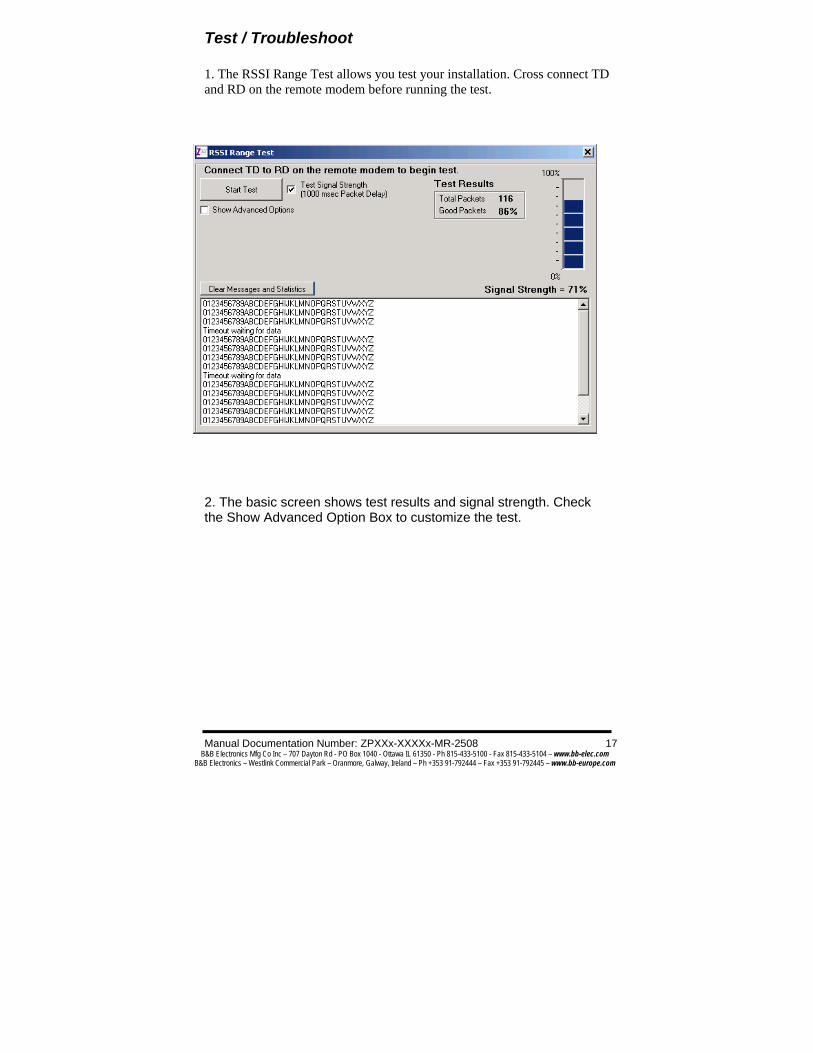
Test / Troubleshoot 1. The RSSI Range Test allows you test your installation. Cross connect TD and RD on the remote modem before running the test.
2. The basic screen shows test results and signal strength. Check the Show Advanced Option Box to customize the test.

18 Manual Documentation Number: ZPXXx-XXXXx-XR-2508 B&B Electronics Mfg Co Inc – 707 Dayton Rd - PO Box 1040 - Ottawa IL 61350 - Ph 815-433-5100 - Fax 815-433-5104 – www.bb-elec.com
B&B Electronics – Westlink Commercial Park – Oranmore, Galway, Ireland – Ph +353 91-792444 – Fax +353 91-792445 – www.bb-europe.com

Manual Documentation Number: ZPXXx-XXXXx-MR-2508 19 B&B Electronics Mfg Co Inc – 707 Dayton Rd - PO Box 1040 - Ottawa IL 61350 - Ph 815-433-5100 - Fax 815-433-5104 – www.bb-elec.com
B&B Electronics – Westlink Commercial Park – Oranmore, Galway, Ireland – Ph +353 91-792444 – Fax +353 91-792445 – www.bb-europe.com
Firmware Update 1. Connect your PC to the radio modem using a straight through serial cable and the auto connect function. The new firmware must be stored on the PC’s local drive. 2. From the Zlinx Manager Radio Modem launch screen, click the firmware update button. 3. Once connected, the software will determine which firmware versions are available on the PC and what version is loaded in the modem. The following screen allows you to chose which firmware version to load.
4. Select the firmware version to load from the pull down menu and click the update button.

20 Manual Documentation Number: ZPXXx-XXXXx-XR-2508 B&B Electronics Mfg Co Inc – 707 Dayton Rd - PO Box 1040 - Ottawa IL 61350 - Ph 815-433-5100 - Fax 815-433-5104 – www.bb-elec.com
B&B Electronics – Westlink Commercial Park – Oranmore, Galway, Ireland – Ph +353 91-792444 – Fax +353 91-792445 – www.bb-europe.com
Specifications RF Properties Physical Standard ZP24D-192RM-MR = Proprietary radio
ZP24D-96RM-MR = Proprietary radio ZP9D-192RM-MR = Proprietary radio ZP9D-115RM-LR = Proprietary radio
Range Radio Dependant ZP24D-****-MR (2.4GHz) = up to 600 feet indoor or 3 mile outdoor ZP9D-****-MR (900MHz) = up to 1500 feet indoor or 7 mile outdoor
Frequency 900MHz/2.4GHz Transmit Power Radio Dependant
ZP9D-****-MR = 100mW (900MHz), ZP24D-****-MR = 50mW (2.4GHz)
Software Zlinx Radio Modem Support Windows 2000, 2003 Server, XP, and Vista
Features AT Command Terminal emulation RSSI signal range test Modem emulation
Antenna Options External Reverse Polarity SMA male jack connector, omni directional (included with product)
Radio Address Defaulted at factory, set by software otherwise Serial settings
Baud 1200, 2400, 4800, 9600, 19200, 38400, 57600 Data bit 7, 8
Parity None, even, odd, mark, space Stop bit 1, 2
RS-232 Connector DB9F DCE
Lines TX, RX, RTS, CTS, DTR, DSR, DCD, RI, GND Connector Removable terminal block
Lines TX, RX, GND RS-422
Connector Removable terminal block Lines 2 or 4 wire – TX+, TX-, RX+, RX-, GND (2 or 4
wire dipswitch selectable) Termination 120 Ohm Dipswitch selectable
RS-485 Connector Removable terminal block
Lines 2 or 4 wire with SD control – TX+, TX-, RX+,

Manual Documentation Number: ZPXXx-XXXXx-MR-2508 21 B&B Electronics Mfg Co Inc – 707 Dayton Rd - PO Box 1040 - Ottawa IL 61350 - Ph 815-433-5100 - Fax 815-433-5104 – www.bb-elec.com
B&B Electronics – Westlink Commercial Park – Oranmore, Galway, Ireland – Ph +353 91-792444 – Fax +353 91-792445 – www.bb-europe.com
RX-, GND (2 or 4 wire dipswitch selectable) SD control Bit wise
Termination 120 Ohm Dipswitch selectable Transistor link failure
No wireless signal or RSSI LED off
Connector Removable terminal block with RS-422/485 Output type Open collector, dry contact, 40mA
Power Supply Connector Removable terminal block
Input Voltage 10–48VDC, 18-30VAC Power
Consumption ZP24D-xxxx-MR = 1.5W max ZP9D-xxxx-MR = 1.5W max
Dimensions 1.2W x 3.3D x 4.7H Environmental Intended for indoor use only
Operating Temperature
-40 to 85ºC (-40 to 185ºF)
Storage Temperature
-40 to 85ºC (-40 to 185ºF)
Operating Humidity
10 to 90% non-condensing
Enclosure Rating
Rating IP30 Mounting DIN rail mount, 35mm
LED Status Front Panel LED Status Power Red = On
OFF = No Power RSSI (Signal Strength)
Green = Strong Yellow = OK Red = Weak OFF = No Signal
Wireless Data Green = Blink on with data
Note: In order for the RSSI LED to continuously indicate the signal strength, set the RP command (RSSI PWM Timer) to FF.
Certifications FCC FCC Part 15 Class B
CE CISPR (EN55022) Class B EN61000-6-1 Generic Standards for Residential,
Commercial, & Light Industrial EN61000-4-2 ESD EN61000-4-3 RFI

22 Manual Documentation Number: ZPXXx-XXXXx-XR-2508 B&B Electronics Mfg Co Inc – 707 Dayton Rd - PO Box 1040 - Ottawa IL 61350 - Ph 815-433-5100 - Fax 815-433-5104 – www.bb-elec.com
B&B Electronics – Westlink Commercial Park – Oranmore, Galway, Ireland – Ph +353 91-792444 – Fax +353 91-792445 – www.bb-europe.com
EN61000-4-4 EFT EN61000-4-5 Surge EN61000-4-6 CI EN61000-4-8 Power Frequency Magnetic EN61000-4-11 Voltage Dips & Interruptions
UL UL, cUL RoHS directive
(lead free) Yes

Manual Documentation Number: ZPXXx-XXXXx-MR-2508 23 B&B Electronics Mfg Co Inc – 707 Dayton Rd - PO Box 1040 - Ottawa IL 61350 - Ph 815-433-5100 - Fax 815-433-5104 – www.bb-elec.com
B&B Electronics – Westlink Commercial Park – Oranmore, Galway, Ireland – Ph +353 91-792444 – Fax +353 91-792445 – www.bb-europe.com
Advanced Programming
Example: Both of the following examples change the module’s destination address to 0x1A0D and save the new address to non-volatile memory. These examples use a PC running hyper terminal connected to the radio modem. Method 1 (One line per command)
Send AT Command System Response +++ OK <CR> (Enter into Command Mode) ATDT <Enter> current Destination Address <CR> (Read) ATDT1A0D <Enter> OK <CR> (Change destination address) ATWR <Enter> OK <CR> (Write to non-volatile memory) ATCN <Enter> OK <CR> (Exit Command Mode)
Method 2 (Multiple commands on one line)
Send AT Command System Response
+++ OK <CR> (Enter into Command Mode) ATDT <Enter> current Destination Address <CR> (Read)
ATDT1A0D,WR,CN <Enter> OK <CR> (Execute commands)
Note: In order to use hyper terminal to send data to the module, PC com port settings must match the baud, parity & stop bit parameters stored in the module.
Use the “PC Settings” tab to configure PC com port settings to match module parameter values.
24 Manual Documentation Number: ZPXXx-XXXXx-XR-2508 B&B Electronics Mfg Co Inc – 707 Dayton Rd - PO Box 1040 - Ottawa IL 61350 - Ph 815-433-5100 - Fax 815-433-5104 – www.bb-elec.com
B&B Electronics – Westlink Commercial Park – Oranmore, Galway, Ireland – Ph +353 91-792444 – Fax +353 91-792445 – www.bb-europe.com
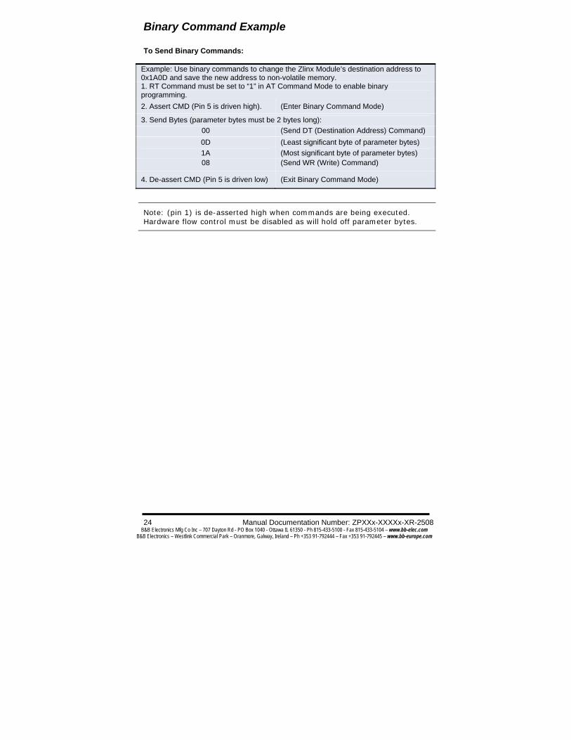
Binary Command Example To Send Binary Commands:
Note: (pin 1) is de-asserted high when commands are being executed. Hardware flow control must be disabled as will hold off parameter bytes.
Example: Use binary commands to change the Zlinx Module’s destination address to 0x1A0D and save the new address to non-volatile memory. 1. RT Command must be set to “1” in AT Command Mode to enable binary programming. 2. Assert CMD (Pin 5 is driven high). (Enter Binary Command Mode)
3. Send Bytes (parameter bytes must be 2 bytes long): 00 (Send DT (Destination Address) Command) 0D (Least significant byte of parameter bytes) 1A (Most significant byte of parameter bytes) 08 (Send WR (Write) Command)
4. De-assert CMD (Pin 5 is driven low) (Exit Binary Command Mode)

Manual Documentation Number: ZPXXx-XXXXx-MR-2508 25 B&B Electronics Mfg Co Inc – 707 Dayton Rd - PO Box 1040 - Ottawa IL 61350 - Ph 815-433-5100 - Fax 815-433-5104 – www.bb-elec.com
B&B Electronics – Westlink Commercial Park – Oranmore, Galway, Ireland – Ph +353 91-792444 – Fax +353 91-792445 – www.bb-europe.com
Command Reference Table Zlinx Commands (The modem expects numerical values in hexadecimal. “d” denotes decimal equivalent.) AT Command
Binary Command
AT Command Name
Range Command Category
# Bytes Returned
Factory Default
AM v4.30* 0x3A (58d) Auto-set MY - Networking & Security - -
AT 0x05 (5d) Guard Time After
0x02 – 0xFFFF [x 100 msec]
Command Mode Options
2 0x0A (10d)
BD v4.2B* 0x15 (21d) Baud Rate
Standard baud rates: 0 – 6 (custom rates also supported)
Serial Interfacing 2
factory-set RF data rate
BK v4.30* 0x2E (46d) Serial Break Passing
0 – 1 Serial Interfacing
1 0
BO v4.30* 0x30 (48d) Serial Break Timeout
0 - 0xFFFF [x 1 second]
Serial Interfacing
2 0
BT 0x04 (4d) Guard Time Before
0 – 0xFFFF [x 100 msec]
Command Mode Options
2 0x0A (10d)
CB v4.30* 0x33 (51d) Connection Duration Timeout
0x01 – 0xFFFF [x 100 msec]
Networking & Security
2 0x28 (4d sec)
CC 0x13 (19d) Command Sequence Character
0x20 – 0x7F
Command Mode Options
1 0x2B (“+”)
CD v4.2B* 0x28 (40d) DO3 Configuration
0 – 4 Serial Interfacing
1 0
CE v4.30* 0x34 (52d) Connection Inactivity Timeout
0 – 0xFFFF [x 10 msec]
Networking & Security
2 0x64 (1d sec)
CF v4.30* 0x35 (53d) Connection Failure
0 – 0xFFF
Networking & Security
2 0

26 Manual Documentation Number: ZPXXx-XXXXx-XR-2508 B&B Electronics Mfg Co Inc – 707 Dayton Rd - PO Box 1040 - Ottawa IL 61350 - Ph 815-433-5100 - Fax 815-433-5104 – www.bb-elec.com
B&B Electronics – Westlink Commercial Park – Oranmore, Galway, Ireland – Ph +353 91-792444 – Fax +353 91-792445 – www.bb-europe.com
Count F CL v4.30* 0x39 (57d) Last
Connection Address
[read-only]
Diagnostics 2 -
CM v4.30* 0x38 (56d) Connection Message
0 – 1 Networking & Security
1 0
CN 0x09 (9d) Exit AT Command Mode
- Command Mode Options
- -
CO v4.30* 0x2F (47d) DO3 Timeout 0 - 0xFFFF [x 1 second]
Serial Interfacing
2 0x03
CS v4.27D*
0x1F (31d) DO2 Configuration
0 – 4 Serial Interfacing
1 0
CT 0x06 (6d) Command Mode Timeout
0x02 – 0xFFFF [x 100 msec]
Command Mode Options
2 0xC8 (200d)
DC v4.30* 0x37 (55d) Disconnect - Networking & Security - -
DR v4.30* 0x2D (45d)
DI3 Configuration
0 – 4 Serial Interfacing
1 0
DT 0x00 (0d) Destination Address
0 – 0xFFFF
Networking & Security
2 0
E0 0x0A (10d) Echo Off -
Command Mode Options
- -
E1 0x0B (11d) Echo On -
Command Mode Options
- -
ER 0x0F (15d) Receive Error Count
0 – 0xFFFF
Diagnostics 2 0
FH 0x0D (13d)
Force Wake-up Initializer - Sleep (Low
Power) - -
FL 0x07 (7d) Software Flow Control
0 – 1 Serial Interfacing
1 0
FT v4.27B*
0x24 (36d) Flow Control Threshold
0 – 0xFF [bytes]
Serial Interfacing
2 varies
GD 0x10 (16d) Receive Good Count
0 – 0xFFFF
Diagnostics 2 0
HP 0x11 (17d) Hopping Channel
0 – 6 Networking & Security
1 0
HT 0x03 (3d) Time before Wake-up Initializer
0 – 0xFFFF [x 100 msec]
Sleep (Low Power)
2 0xFFFF
ID v4.2B* 0x27 (39d) Modem VID User-settabl
Networking & Security 2 -

Manual Documentation Number: ZPXXx-XXXXx-MR-2508 27 B&B Electronics Mfg Co Inc – 707 Dayton Rd - PO Box 1040 - Ottawa IL 61350 - Ph 815-433-5100 - Fax 815-433-5104 – www.bb-elec.com
B&B Electronics – Westlink Commercial Park – Oranmore, Galway, Ireland – Ph +353 91-792444 – Fax +353 91-792445 – www.bb-europe.com
e: 0x10 - 0x7FFF Read-only: 0x8000 – 0xFFFF
IU v4.30* 0x3B (59d) DI2, DI3 Update Timer
0 - 0xFFFF [x 100 msec]
Serial Interfacing
2 0x0A (10d)
LH 0x0C (12d)
Wake-up Initializer Timer
0 – 0xFF [x 100 msec]
Sleep (Low Power)
1 0x01
MD v4.30* 0x32 (50d) RF Mode 0 – 4 Networking & Security
1 0
MK 0x12 (18d) Address Mask
0 – 0xFFFF
Networking & Security
2 0xFFFF
MY v4.30* 0x2A (42d) Source Address
0 – 0xFFFF
Networking & Security
2 0xFFFF
NB v4.30* 0x23 (35d) Parity 0 – 5 Serial Interfacing
1 0
PC v4.22* 0x1E (30d) Power-up Mode
0 – 1 Command Mode Options
1 0
PK v4.30* 0x29 (41d) RF Packet Size
0 - 0x100 [bytes]
Serial Interfacing
2 0x40 (64d)
PW v4.22* 0x1D (29d)
Pin Wake-up 0 – 1 Sleep (Low Power)
1 0
RB v4.30* 0x20 (32d) Packetization Threshold
0 - 0x100 [bytes]
Serial Interfacing
2 0x01
RE 0x0E (14d) Restore Defaults - (Special) - -
RN v4.22* 0x19 (25d) Delay Slots 0 – 0xFF [slots]
Networking & Security
1 0
RO v4.2A* 0x21 (33d) Packetization Timeout
0 – 0xFFFF [x 200 µsec]
Serial Interfacing
2 0
RP v4.2A* 0x22 (34d) RSSI PWM Timer
0 - 0x7F [x 100 msec]
Diagnostics 1 0
RR v4.22* 0x18 (24d) Retries 0 – 0xFF
Networking & Security
1 0
28 Manual Documentation Number: ZPXXx-XXXXx-XR-2508 B&B Electronics Mfg Co Inc – 707 Dayton Rd - PO Box 1040 - Ottawa IL 61350 - Ph 815-433-5100 - Fax 815-433-5104 – www.bb-elec.com
B&B Electronics – Westlink Commercial Park – Oranmore, Galway, Ireland – Ph +353 91-792444 – Fax +353 91-792445 – www.bb-europe.com
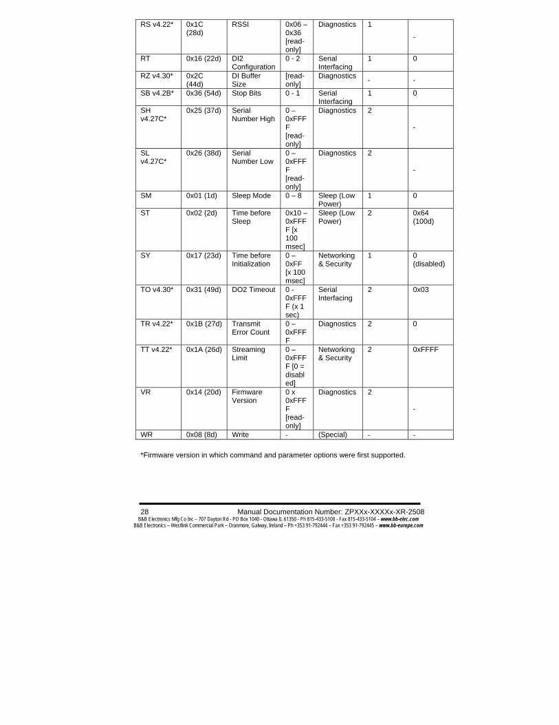
RS v4.22* 0x1C (28d)
RSSI 0x06 – 0x36 [read-only]
Diagnostics 1
-
RT 0x16 (22d) DI2 Configuration
0 - 2 Serial Interfacing
1 0
RZ v4.30* 0x2C (44d)
DI Buffer Size
[read-only]
Diagnostics - -
SB v4.2B* 0x36 (54d) Stop Bits 0 - 1 Serial Interfacing
1 0
SH v4.27C*
0x25 (37d) Serial Number High
0 – 0xFFFF [read-only]
Diagnostics 2
-
SL v4.27C*
0x26 (38d) Serial Number Low
0 – 0xFFFF [read-only]
Diagnostics 2
-
SM 0x01 (1d) Sleep Mode 0 – 8 Sleep (Low Power)
1 0
ST 0x02 (2d) Time before Sleep
0x10 – 0xFFFF [x 100 msec]
Sleep (Low Power)
2 0x64 (100d)
SY 0x17 (23d) Time before Initialization
0 – 0xFF [x 100 msec]
Networking & Security
1 0 (disabled)
TO v4.30* 0x31 (49d) DO2 Timeout 0 - 0xFFFF (x 1 sec)
Serial Interfacing
2 0x03
TR v4.22* 0x1B (27d) Transmit Error Count
0 – 0xFFFF
Diagnostics 2 0
TT v4.22* 0x1A (26d) Streaming Limit
0 – 0xFFFF [0 = disabled]
Networking & Security
2 0xFFFF
VR 0x14 (20d) Firmware Version
0 x 0xFFFF [read-only]
Diagnostics 2
-
WR 0x08 (8d) Write - (Special) - - *Firmware version in which command and parameter options were first supported.

Manual Documentation Number: ZPXXx-XXXXx-MR-2508 29 B&B Electronics Mfg Co Inc – 707 Dayton Rd - PO Box 1040 - Ottawa IL 61350 - Ph 815-433-5100 - Fax 815-433-5104 – www.bb-elec.com
B&B Electronics – Westlink Commercial Park – Oranmore, Galway, Ireland – Ph +353 91-792444 – Fax +353 91-792445 – www.bb-europe.com
Zlinx Command Descriptions Command descriptions in this section are listed alphabetically. Command categories are designated within “< >” symbols that follow each command title. Zlinx Modules expect parameter numerical values in hexadecimal (designated by the “0x” prefix). AM (Auto-set MY) Command <Networking & Security> AM Command is used to automatically set the MY (Source Address) parameter from the factory-set module serial number. The address is formed with bits 29, 28 and 13-0 of the serial number (in that order). AT (Guard Time After) Command <Command Mode Options> AT Command is used to set the DI time-of-silence that follows the AT command sequence character (CC Command). By default, AT Command Mode will activate after one second of silence. Refer to the AT Commands section to view the default AT Command Mode Sequence. BD (Interface Data Rate) Command
NOTE: AT Commands issued without a parameter value will return the currently stored parameter.
AT Command: ATAM Binary Command: 0x3A (58 decimal) Minimum firmware version required: 4.40
Binary Command: 0x05 (5 decimal)
Parameter Range:
0x02 – 0xFFFF [x 100 milliseconds]
Number of bytes returned: 2
Default Parameter Value: 0x0A (10 decimal) Related Commands: BT (Guard Time Before), CC (Command Sequence Character)
30 Manual Documentation Number: ZPXXx-XXXXx-XR-2508 B&B Electronics Mfg Co Inc – 707 Dayton Rd - PO Box 1040 - Ottawa IL 61350 - Ph 815-433-5100 - Fax 815-433-5104 – www.bb-elec.com
B&B Electronics – Westlink Commercial Park – Oranmore, Galway, Ireland – Ph +353 91-792444 – Fax +353 91-792445 – www.bb-europe.com
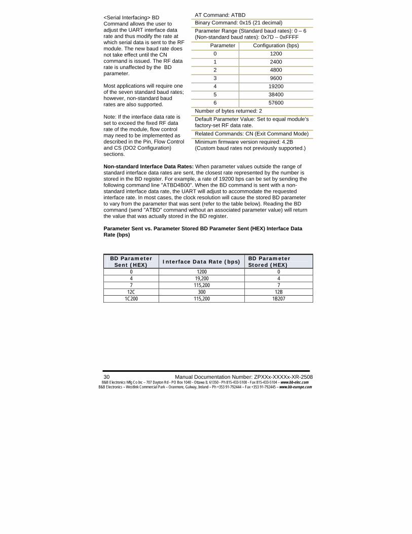
<Serial Interfacing> BD Command allows the user to adjust the UART interface data rate and thus modify the rate at which serial data is sent to the RF module. The new baud rate does not take effect until the CN command is issued. The RF data rate is unaffected by the BD parameter. Most applications will require one of the seven standard baud rates; however, non-standard baud rates are also supported. Note: If the interface data rate is set to exceed the fixed RF data rate of the module, flow control may need to be implemented as described in the Pin, Flow Control and CS (DO2 Configuration) sections. Non-standard Interface Data Rates: When parameter values outside the range of standard interface data rates are sent, the closest rate represented by the number is stored in the BD register. For example, a rate of 19200 bps can be set by sending the following command line "ATBD4B00". When the BD command is sent with a non-standard interface data rate, the UART will adjust to accommodate the requested interface rate. In most cases, the clock resolution will cause the stored BD parameter to vary from the parameter that was sent (refer to the table below). Reading the BD command (send "ATBD" command without an associated parameter value) will return the value that was actually stored in the BD register. Parameter Sent vs. Parameter Stored BD Parameter Sent (HEX) Interface Data Rate (bps)
BD Parameter
Sent (HEX) Interface Data Rate (bps)
BD Parameter Stored (HEX)
0 1200 0 4 19,200 4 7 115,200 7
12C 300 12B 1C200 115,200 1B207
AT Command: ATBD Binary Command: 0x15 (21 decimal) Parameter Range (Standard baud rates): 0 – 6 (Non-standard baud rates): 0x7D – 0xFFFF
Parameter Configuration (bps) 0 1200 1 2400 2 4800 3 9600 4 19200 5 38400 6 57600
Number of bytes returned: 2 Default Parameter Value: Set to equal module’s factory-set RF data rate. Related Commands: CN (Exit Command Mode) Minimum firmware version required: 4.2B (Custom baud rates not previously supported.)

Manual Documentation Number: ZPXXx-XXXXx-MR-2508 31 B&B Electronics Mfg Co Inc – 707 Dayton Rd - PO Box 1040 - Ottawa IL 61350 - Ph 815-433-5100 - Fax 815-433-5104 – www.bb-elec.com
B&B Electronics – Westlink Commercial Park – Oranmore, Galway, Ireland – Ph +353 91-792444 – Fax +353 91-792445 – www.bb-europe.com
BK (Serial Break Passing) Command <Serial Interfacing> Pass a serial break condition on the DI pin to the DO pin of another module.
BO (Serial Break Timeout) Command <Serial Interfacing> DO pin will return to default after no serial break status information is received during the timeout period. Use with BK parameter = 1.
BT (Guard Time Before) Command <Command Mode Options> BT Command is used to set the DI pin silence time that must precede the command sequence character (CC Command) of the AT Command Mode Sequence. Refer to the AT Commands section to view the default AT Command Mode sequence.
AT Command: ATBK
Binary Command: 0x2E (46 decimal)
Parameter Range: 0 – 1
Parameter Configuration
0 disable
1 enable
Default Parameter Value: 0
Number of bytes returned: 1
Related Commands: BO (Serial Break Timeout)
Minimum Firmware Version Required: 4.30
AT Command: ATBO
Binary Command: 0x30 (48 decimal)
Parameter Range: 0 – 0xFFFF [x 1 second]
Default Parameter Value: 0
Number of bytes returned: 2
Related Commands: BK (Serial Break Passing)
Minimum Firmware Version Required: 4.30
AT Command: ATBT
Binary Command: 0x04 (4 decimal) Parameter Range: 0 – 0xFFFF
[x 100 milliseconds]
Default Parameter Value: 0x0A (10 decimal)
Number of bytes returned: 2 Related Commands: AT (Guard Time After), CC (Command Sequence Character)

32 Manual Documentation Number: ZPXXx-XXXXx-XR-2508 B&B Electronics Mfg Co Inc – 707 Dayton Rd - PO Box 1040 - Ottawa IL 61350 - Ph 815-433-5100 - Fax 815-433-5104 – www.bb-elec.com
B&B Electronics – Westlink Commercial Park – Oranmore, Galway, Ireland – Ph +353 91-792444 – Fax +353 91-792445 – www.bb-europe.com
CB (Connection Duration Timeout) Command <Networking & Security> Set/Read the maximum amount of time an exclusive connection between a base and remote module in a point-to-multipoint network is sustained. The remote module will disconnect when this timeout expires. CC (Command Sequence Character) Command <Command Mode Options> CC Command is used to set the ASCII character to be used between Guard Times of the AT Command Mode Sequence (BT+ CC + AT). The AT Command Mode Sequence activates AT Command Mode (from Idle Mode). Refer to the AT Commands section to view the default AT Command Mode sequence. CD (DO3 Configuration) Command <Serial Interfacing> CD Command is used to redefine the behavior of the DO3 (Data Output 3)/RX LED line.
CE (Connection Inactivity Timeout) Command <Networking & Security> Set/Read the duration of inactivity that will cause a break in a connection between modules. The base module will disconnect when no payload has been transferred for the time specified by the CE parameter.
Binary Command: 0x33 (51 decimal) Parameter Range: 0x01 – 0xFFFF
[x 100 milliseconds]
Default Parameter Value: 0x28 (4d seconds)
Number of bytes returned: 2 Related Commands: CE (Connection Inactivity Timeout), DC (Disconnect), MD (RF Mode)
Minimum Firmware Version Required: 4.30
AT Command: ATCC
Binary Command: 0x13 (19 decimal)
Parameter Range: 0x20 – 0x7F
Default Parameter Value: 0x2B (ASCII “+” sign)
Number of bytes returned: 1 Related Commands: AT (Guard Time After), BT (Guard Time Before)
AT Command: ATCD Binary Command: 0x28 (40 decimal)
Parameter Range: 0 – 4
Parameter Configuration 0 RX LED 1 Default high 2 Default low 3 (reserved)
4 Assert only when packet addressed to module sent
Default Parameter Value: 0 Number of bytes returned: 1 Minimum Firmware Version Required: 4.2B
AT Command: ATCE Binary Command: 0x34 (52 decimal) Parameter Range: 0 – 0xFFFF
[x 10 milliseconds] Default Parameter Value: 0x64 (1d second) Number of bytes returned: 2 Related Commands: CB ( Connection Duration Timeout), DC (Disconnect), MD (RF Mode) Minimum Firmware Version Required: 4.30
Manual Documentation Number: ZPXXx-XXXXx-MR-2508 33 B&B Electronics Mfg Co Inc – 707 Dayton Rd - PO Box 1040 - Ottawa IL 61350 - Ph 815-433-5100 - Fax 815-433-5104 – www.bb-elec.com
B&B Electronics – Westlink Commercial Park – Oranmore, Galway, Ireland – Ph +353 91-792444 – Fax +353 91-792445 – www.bb-europe.com
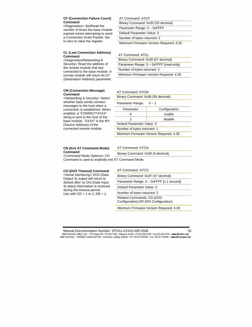
CF (Connection Failure Count) Command <Diagnostics> Set/Read the number of times the base module expired retries attempting to send a Connection Grant Packet. Set to zero to clear the register. CL (Last Connection Address) Command <Diagnostics/Networking & Security> Read the address of the remote module that last connected to the base module. A remote module will return its DT (Destination Address) parameter. CM (Connection Message) Command <Networking & Security> Select whether base sends connect messages to the host when a connection is established. When enabled, a “CONNECTXXXX” string is sent to the host of the base module. “XXXX” is the MY (Source Address) of the connected remote module.
CN (Exit AT Command Mode) Command <Command Mode Options> CN Command is used to explicitly exit AT Command Mode. CO (DO3 Timeout) Command <Serial Interfacing> DO3 (Data Output 3) output will return to default after no DI3 (Data Input 3) status information is received during the timeout period. Use with CD = 1 or 2, DR = 1.
AT Command: ATCF Binary Command: 0x35 (53 decimal) Parameter Range: 0 – 0xFFFF Default Parameter Value: 0 Number of bytes returned: 2 Minimum Firmware Version Required: 4.30
AT Command: ATCL Binary Command: 0x39 (57 decimal) Parameter Range: 0 – 0xFFFF [read-only] Number of bytes returned: 2 Minimum Firmware Version Required: 4.30
AT Command: ATCM Binary Command: 0x38 (56 decimal)
Parameter Range: 0 – 1
Parameter Configuration 0 enable 1 disable
Default Parameter Value: 0 Number of bytes returned: 1 Minimum Firmware Version Required: 4.30
AT Command: ATCN
Binary Command: 0x09 (9 decimal)
AT Command: ATCO
Binary Command: 0x2F (47 decimal)
Parameter Range: 0 – 0xFFFF [x 1 second]
Default Parameter Value: 3
Number of bytes returned: 2 Related Commands: CD (DO3 Configuration),DR (DI3 Configuration)
Minimum Firmware Version Required: 4.30

34 Manual Documentation Number: ZPXXx-XXXXx-XR-2508 B&B Electronics Mfg Co Inc – 707 Dayton Rd - PO Box 1040 - Ottawa IL 61350 - Ph 815-433-5100 - Fax 815-433-5104 – www.bb-elec.com
B&B Electronics – Westlink Commercial Park – Oranmore, Galway, Ireland – Ph +353 91-792444 – Fax +353 91-792445 – www.bb-europe.com
CS (DO2 Configuration) Command <Serial Interfacing> CS Command is used to select the behavior of the DO2 (Data Output 2) pin signal. This output can provide RS-232 flow control, control the TX enable signal (for RS-485 or RS-422 operations), or set the default level for the I/O line passing function. By default, DO2 provides RS-232 (Clear-to- Send) flow control.
CT (Command Mode Timeout) Command <Command Mode Options> CT Command is used to set the amount of time of inactivity before AT Command Mode automatically terminates. After a CT time of inactivity, the module exits AT Command Mode and returns to Idle Mode. AT Command Mode can also be exited manually using the CN (Exit AT Command Mode) Command. DC (Disconnect) Command <Networking & Security> DC Command is used (when in Multi-Streaming Mode (MD = 1 or 2)) to explicitly force the disconnection of an active exclusive connection. If MD = 1, the base module will force the disconnection of an exclusive connection. If MD = 2, the remote module will send a “Disconnect Request Packet” to the base module
AT Command: ATCS
Binary Command: 0x1F (31 decimal)
Parameter Range: 0 – 4
Parameter Configuration
0 RS-232 flow control
1 RS-485 TX enable low
2 high
3 RS-485 TX enable high
4 low
Default Parameter Value: 0
Number of bytes returned: 1 Related Commands: RT (DI2 Configuration), TO (DO2 Timeout)
Minimum Firmware Version Required: 4.27D
AT Command: ATCT
Binary Command: 0x06 (6 decimal) Parameter Range: 2 – 0xFFFF
[x 100 milliseconds]
Default Parameter Value: 0xC8 (200 decimal, 20 seconds)
Number of bytes returned: 2
AT Command: ATDC
Binary Command: 0x37 (55 decimal) Related Commands: CB (Connection Duration Timeout), CE (Connection Inactivity Timeout), MD (RF Mode)
Minimum Firmware Version Required: 4.30

Manual Documentation Number: ZPXXx-XXXXx-MR-2508 35 B&B Electronics Mfg Co Inc – 707 Dayton Rd - PO Box 1040 - Ottawa IL 61350 - Ph 815-433-5100 - Fax 815-433-5104 – www.bb-elec.com
B&B Electronics – Westlink Commercial Park – Oranmore, Galway, Ireland – Ph +353 91-792444 – Fax +353 91-792445 – www.bb-europe.com
DR (DI3 Configuration) Command <Serial Interfacing> DR Command is used to configure DI3 (pin 2, SLEEP) for I/O line passing (use with CD = 1 or 2 and CO) or controlling connection status (use with MD = 1 or 2).
DT (Destination Address) Command <Networking & Security> DT Command is used to set the networking address of an Zlinx Module. Zlinx Modules use three filtration layers: Channels (ATHP), Vendor Identification Number (ATID) and Destination Addresses (ATDT). DT Command assigns an address to a module that enables it to communicate only with other modules having the same addresses. All modules that share the same Destination Address can communicate freely with each other. Modules in the same network with a different Destination Address (than that of the transmitter) will listen to all transmissions to stay synchronized, but will not send any of the data out their serial ports. E0 (Echo Off) Command <Command Mode Options> The E0 command turns off character echo in AT Command Mode. By default, echo is off.
AT Command: ATDR
Binary Command: 0x2D (45 decimal) Parameter Range: 0 – 4
Parameter Configuration
0 Disabled
1 DI3 I/O passing enabled
2 Connect on low
3 Disconnect on high
4 Connect and Disconnect
Default Parameter Value: 0
Number of bytes returned: 1 Related Commands: CD (DO3 Configuration),CO (DO3 Timeout), MD (RF Mode)
Minimum Firmware Version Required: 4.30
AT Command: ATDT
Binary Command: 0x00
Parameter Range: 0 – 0xFFFF
Default Parameter Value: 0
Number of bytes returned: 2 Related Commands: HP (Hopping Channel), ID (Module VID), MK (Address Mask)
AT Command: ATE0
Binary Command: 0x0A (10 decimal)

36 Manual Documentation Number: ZPXXx-XXXXx-XR-2508 B&B Electronics Mfg Co Inc – 707 Dayton Rd - PO Box 1040 - Ottawa IL 61350 - Ph 815-433-5100 - Fax 815-433-5104 – www.bb-elec.com
B&B Electronics – Westlink Commercial Park – Oranmore, Galway, Ireland – Ph +353 91-792444 – Fax +353 91-792445 – www.bb-europe.com
E1 (Echo On) Command <Command Mode Options> E1 Command turns on the echo in AT Command Mode. Each typed character will be echoed back to the terminal when ATE1 is active. E0 is the default. ER (Receive Error Count) Command <Diagnostics> Set/Read the receive error count. The error-count records the number of packets partially received then aborted on reception error. This value returns to 0 after a reset and is not non-volatile (value does not persist in the module’s memory after a power-up sequence). Once the receive error count reaches its maximum value (up to 0xFFFF), it remains at its maximum count value until the maximum count value is explicitly changed or the module is reset. FH (Force Wake-up Initializer) Command <Sleep (Low Power)> FH Command is used to force a Wake-up Initializer to be sent on the next transmission. WR (Write) Command does not need to be issued with FH Command. Use only with cyclic sleep modes active on remote modules. FL (Software Flow Control) Command <Serial Interfacing> FL Command is used to configure of module with software flow control. Hardware flow control is implemented with the Zlinx Module as the DO2 pin ( ), which regulates when serial data can be transferred to the module. FL Command is used to allow software flow control. XON character used is 0x11 (17 decimal). XOFF character used is 0x13 (19 decimal).
AT Command: ATE1
Binary Command: 0x0B (11 decimal)
AT Command: ATER
Binary Command: 0x0F (15 decimal)
Parameter Range: 0 – 0xFFFF
Default Parameter Value: 0
Number of bytes returned: 2
Related Commands: GD (Receive Good Count)
AT Command: ATFH
Binary Command: 0x0D (13 decimal)
AT Command: ATFL
Binary Command: 0x07 (7 decimal)
Parameter Range: 0 – 1
Parameter Configuration
0 Disable software flow control
1 Enable software flow control
Default Parameter Value: 0
Number of bytes returned: 1
Manual Documentation Number: ZPXXx-XXXXx-MR-2508 37 B&B Electronics Mfg Co Inc – 707 Dayton Rd - PO Box 1040 - Ottawa IL 61350 - Ph 815-433-5100 - Fax 815-433-5104 – www.bb-elec.com
B&B Electronics – Westlink Commercial Park – Oranmore, Galway, Ireland – Ph +353 91-792444 – Fax +353 91-792445 – www.bb-europe.com
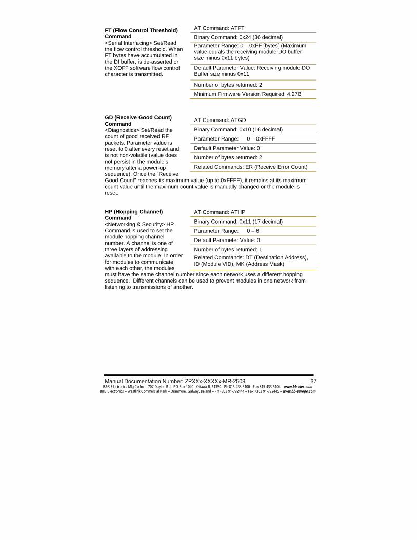
FT (Flow Control Threshold) Command <Serial Interfacing> Set/Read the flow control threshold. When FT bytes have accumulated in the DI buffer, is de-asserted or the XOFF software flow control character is transmitted.
GD (Receive Good Count) Command <Diagnostics> Set/Read the count of good received RF packets. Parameter value is reset to 0 after every reset and is not non-volatile (value does not persist in the module’s memory after a power-up sequence). Once the “Receive Good Count” reaches its maximum value (up to 0xFFFF), it remains at its maximum count value until the maximum count value is manually changed or the module is reset. HP (Hopping Channel) Command <Networking & Security> HP Command is used to set the module hopping channel number. A channel is one of three layers of addressing available to the module. In order for modules to communicate with each other, the modules must have the same channel number since each network uses a different hopping sequence. Different channels can be used to prevent modules in one network from listening to transmissions of another.
AT Command: ATFT
Binary Command: 0x24 (36 decimal) Parameter Range: 0 – 0xFF [bytes] (Maximum value equals the receiving module DO buffer size minus 0x11 bytes)
Default Parameter Value: Receiving module DO Buffer size minus 0x11
Number of bytes returned: 2
Minimum Firmware Version Required: 4.27B
AT Command: ATGD
Binary Command: 0x10 (16 decimal)
Parameter Range: 0 – 0xFFFF
Default Parameter Value: 0
Number of bytes returned: 2
Related Commands: ER (Receive Error Count)
AT Command: ATHP
Binary Command: 0x11 (17 decimal)
Parameter Range: 0 – 6
Default Parameter Value: 0
Number of bytes returned: 1 Related Commands: DT (Destination Address), ID (Module VID), MK (Address Mask)
38 Manual Documentation Number: ZPXXx-XXXXx-XR-2508 B&B Electronics Mfg Co Inc – 707 Dayton Rd - PO Box 1040 - Ottawa IL 61350 - Ph 815-433-5100 - Fax 815-433-5104 – www.bb-elec.com
B&B Electronics – Westlink Commercial Park – Oranmore, Galway, Ireland – Ph +353 91-792444 – Fax +353 91-792445 – www.bb-europe.com
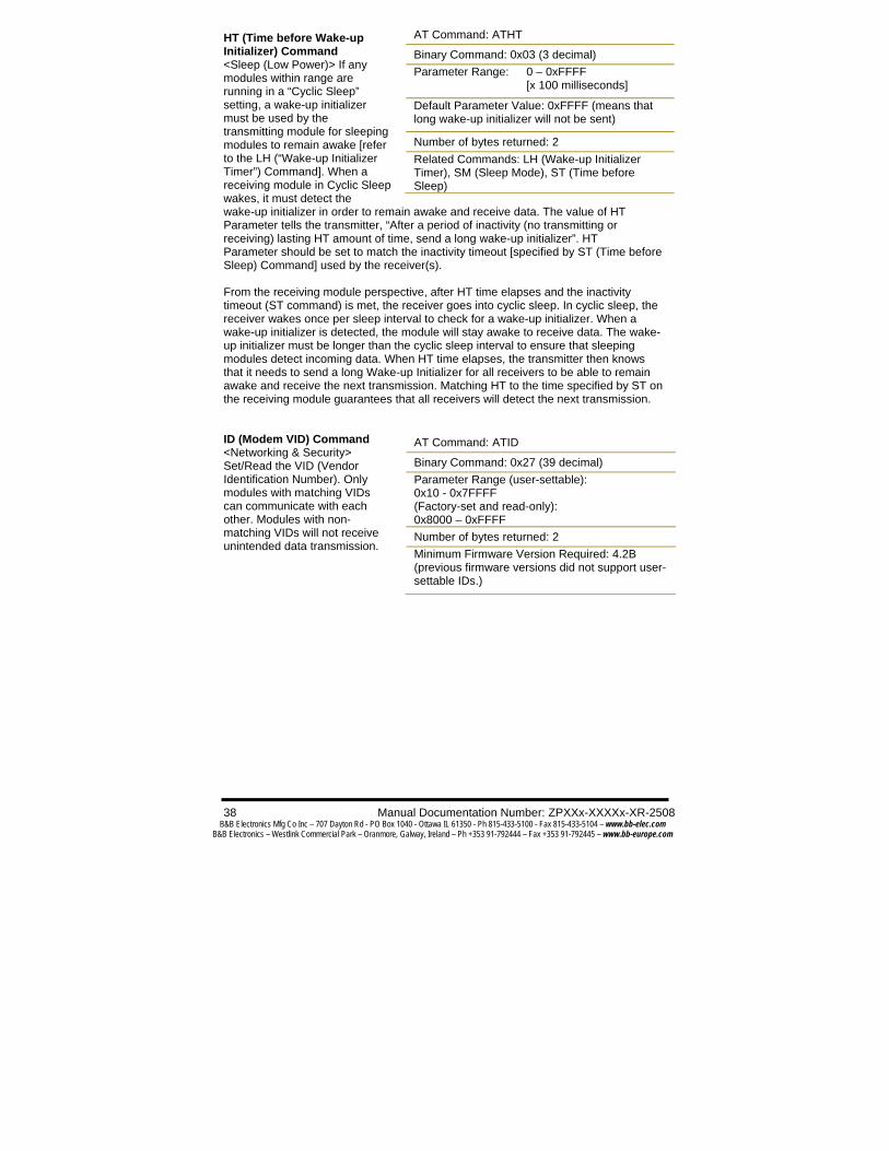
HT (Time before Wake-up Initializer) Command <Sleep (Low Power)> If any modules within range are running in a “Cyclic Sleep” setting, a wake-up initializer must be used by the transmitting module for sleeping modules to remain awake [refer to the LH (“Wake-up Initializer Timer”) Command]. When a receiving module in Cyclic Sleep wakes, it must detect the wake-up initializer in order to remain awake and receive data. The value of HT Parameter tells the transmitter, “After a period of inactivity (no transmitting or receiving) lasting HT amount of time, send a long wake-up initializer”. HT Parameter should be set to match the inactivity timeout [specified by ST (Time before Sleep) Command] used by the receiver(s). From the receiving module perspective, after HT time elapses and the inactivity timeout (ST command) is met, the receiver goes into cyclic sleep. In cyclic sleep, the receiver wakes once per sleep interval to check for a wake-up initializer. When a wake-up initializer is detected, the module will stay awake to receive data. The wake-up initializer must be longer than the cyclic sleep interval to ensure that sleeping modules detect incoming data. When HT time elapses, the transmitter then knows that it needs to send a long Wake-up Initializer for all receivers to be able to remain awake and receive the next transmission. Matching HT to the time specified by ST on the receiving module guarantees that all receivers will detect the next transmission. ID (Modem VID) Command <Networking & Security> Set/Read the VID (Vendor Identification Number). Only modules with matching VIDs can communicate with each other. Modules with non-matching VIDs will not receive unintended data transmission.
AT Command: ATHT
Binary Command: 0x03 (3 decimal) Parameter Range: 0 – 0xFFFF
[x 100 milliseconds]
Default Parameter Value: 0xFFFF (means that long wake-up initializer will not be sent)
Number of bytes returned: 2 Related Commands: LH (Wake-up Initializer Timer), SM (Sleep Mode), ST (Time before Sleep)
AT Command: ATID
Binary Command: 0x27 (39 decimal) Parameter Range (user-settable): 0x10 - 0x7FFFF (Factory-set and read-only): 0x8000 – 0xFFFF Number of bytes returned: 2 Minimum Firmware Version Required: 4.2B (previous firmware versions did not support user-settable IDs.)

Manual Documentation Number: ZPXXx-XXXXx-MR-2508 39 B&B Electronics Mfg Co Inc – 707 Dayton Rd - PO Box 1040 - Ottawa IL 61350 - Ph 815-433-5100 - Fax 815-433-5104 – www.bb-elec.com
B&B Electronics – Westlink Commercial Park – Oranmore, Galway, Ireland – Ph +353 91-792444 – Fax +353 91-792445 – www.bb-europe.com
IU (DI2, DI3 Update Timer) Command <Serial Interfacing> Set/Read the interval at which the status of DI2, DI3 and Break is transmitted. Additionally, status is transmitted whenever there is a transition. A setting of “0” disables periodic update. DI2 or DI3 passing must be enabled for the update to take place.
LH (Wake-up Initializer Timer) Command <Sleep (Low Power)> Set/Read the amount of time during which the RF initializer is sent. When receiving modules are put into Cyclic Sleep Mode, they power-down after a period of inactivity [specified by ST (Time before Sleep) Command] and will periodically awaken and listen for transmitted data. In order for the receiving modules to remain awake, they must detect ~35ms of the wake-up initializer. LH Command must be used whenever a receiver is operating in Cyclic Sleep Mode. This lengthens the Wake-up Initializer to a specific amount of time (in tenths of a second). The Wake-up Initializer Time must be longer than the cyclic sleep time that is determined by SM (Sleep Mode) Command. If the wake-up initializer time were less than the Cyclic Sleep interval, the connection would be at risk of missing the wake-up initializer transmission.
AT Command: ATIU
Binary Command: 0x3B (59 decimal)
Parameter Range: 0 - 0xFFFF [x 100 ms]
Default Parameter Value: 0x0A (10 decimal)
Number of bytes returned: 2 Related Commands: BK (Serial Break Passing), BO (Serial Break Timeout), CO (DO3 Timeout), DR (Disconnect), RT (DI2 Configuration), TO (DO2 Timeout)
Minimum Firmware Version Required: 4.30
AT Command: ATLH
Binary Command: 0x0C (12 decimal) Parameter Range: 0 – 0xFF
[x 100 milliseconds]
Default Parameter Value: 1
Number of bytes returned: 1 Related Commands: HT (Time before Wake-up Initializer), SM (Sleep Mode), ST (Time before Sleep)
Refer to the figures in the Sleep Mode sections to view correct and incorrect configuration diagrams. The images help visualize the importance that the LH value be greater than the SM cyclic sleep value.

40 Manual Documentation Number: ZPXXx-XXXXx-XR-2508 B&B Electronics Mfg Co Inc – 707 Dayton Rd - PO Box 1040 - Ottawa IL 61350 - Ph 815-433-5100 - Fax 815-433-5104 – www.bb-elec.com
B&B Electronics – Westlink Commercial Park – Oranmore, Galway, Ireland – Ph +353 91-792444 – Fax +353 91-792445 – www.bb-europe.com
MD (RF Mode) Command <Networking & Security> The MD command is used to select/read the RF Mode (Peer-to-peer, Multi-Stream or Repeater Modes) of the module. Multi-Streaming Mode enables exclusive connections in point-to-multipoint networks. Refer to the Multi-Streaming Mode section for more information regarding how these parameter values affect other parameter values. Repeater Mode enables longer range via an intermediary module. When MD=3, the module will act as a “store and forward” repeater. Any packets not addressed to this node will be repeated. A Repeater End Node (MD=4) handles repeated messages, but will not forward the data over-the-air. MK (Address Mask) Command <Networking & Security> MK Command is used to set/read the address mask of the module. All data packets contain the destination address (DT Parameter) of the transmitting module. When an RF data packet is received, the transmitter’s destination address is logically “ANDed” (bitwise) with the Address Mask of the receiver. The resulting value must match the destination address or the address mask of the receiver for the packet to be received and sent out the module DO serial port. If the “ANDed” value does not match either the destination address or the address mask of the receiver, the packet is discarded. (All “0” values are treated as “irrelevant” values and are ignored.)
AT Command: ATMD
Binary Command: 0x32 (50 decimal)
Parameter Range: 0 – 4
Parameter Configuration
0 Peer-to-Peer (transparent operation)
1 Multi-Stream Base
2 Multi-Stream Remote
3 Repeater & End Node
4 End Node
Default Parameter Value: 0
Number of bytes returned: 1 Related Commands: CB (Connection Duration Timeout), CE (Connection Inactivity Timeout), CM (Connection Message), DC (Disconnect)
Minimum Firmware Version Required: 4.30
AT Command: ATMK
Binary Command: 0x12 (18 decimal)
Parameter Range: 0 – 0xFFFF Default Parameter Value: 0xFFFF (Destination address (DT parameter) of the transmitting module must exactly match the destination address of the receiving module.)
Number of bytes returned: 2 Related Commands: DT (Destination Address), HP (Hopping Channel), ID (Module VID), MY (Source Address)

Manual Documentation Number: ZPXXx-XXXXx-MR-2508 41 B&B Electronics Mfg Co Inc – 707 Dayton Rd - PO Box 1040 - Ottawa IL 61350 - Ph 815-433-5100 - Fax 815-433-5104 – www.bb-elec.com
B&B Electronics – Westlink Commercial Park – Oranmore, Galway, Ireland – Ph +353 91-792444 – Fax +353 91-792445 – www.bb-europe.com
MY (Source Address) Command <Networking & Security> Set/Read the source address of the module.
NB (Parity) Command <Serial Interfacing> Select/Read parity settings for UART communications.
PC (Power-up Mode) Command <Command Mode Options> PC Command allows the module to power-up directly into AT Command Mode from reset or power-on. If PC Command is enabled with SM Parameter set to 1, DI3 (pin 2) can be used to enter the module into AT Command Mode. When the DI3 pin is deasserted (low), the module will wake-up in AT Command Mode. This behavior allows module DTR emulation.
AT Command: ATMY
Binary Command: 0x2A (42 decimal)
Parameter Range: 0 – 0xFFFF Default Parameter Value: 0xFFFF (Disabled – the DT (Destination Address) parameter serves as both source and destination address.)
Number of bytes returned: 2 Related Commands: DT (Destination Address), HP (Hopping Channel), ID (Modem VID), MK (Address Mask), AM (Auto-set MY)
Minimum Firmware Version Required: 4.30
AT Command: ATNB
Binary Command: 0x23 (35 decimal)
Parameter Range: 0 – 5
Parameter Configuration
0 8-bit (no parity or 7-bit (any parity)
1 8-bit even
2 8-bit odd
3 8-bit mark
4 8-bit space
5 9-bit
Default Parameter Value: 0
Number of bytes returned: 1 Minimum Firmware Version Required: 4.30 (previous versions did not support the 9thbit.
AT Command: ATPC Binary Command: 0x1E (30 decimal)
Parameter Range: 0 – 1 Parameter Configuration 0 Power-up to Idle Mode
1 Power-up to AT Command Mode
Default Parameter Value: 0 Number of bytes returned: 1 Minimum Firmware Version Required: 4.22

42 Manual Documentation Number: ZPXXx-XXXXx-XR-2508 B&B Electronics Mfg Co Inc – 707 Dayton Rd - PO Box 1040 - Ottawa IL 61350 - Ph 815-433-5100 - Fax 815-433-5104 – www.bb-elec.com
B&B Electronics – Westlink Commercial Park – Oranmore, Galway, Ireland – Ph +353 91-792444 – Fax +353 91-792445 – www.bb-europe.com
PK (RF Packet Size) Command <Serial Interfacing> Set/Read the maximum size of the RF packets sent out a transmitting module. The maximum packet size can be used along with the RB and RO parameters to implicitly set the channel dwell time. Changes to this parameter may have a secondary effect on the RB (Packet Control Characters) parameter. RB must always be less than or equal to PK. If PK is changed to a value less than the current value of RB, RB is automatically lowered to be equal to PK. PW (Pin Wake-up) Command <Sleep (Low Power)> Under normal operation, a module in Cyclic Sleep Mode cycles from an active state to a low-power state at regular intervals until data is ready to be received. If the PW Parameter is set to 1, SLEEP (pin 2) can be used to wake the module from Cyclic Sleep. If the SLEEP pin is de-asserted (low), the module will be fully operational and will not go into Cyclic Sleep. Once SLEEP is asserted, the module will remain active for the period of time specified by ST (Time before Sleep) Command and will return to Cyclic Sleep Mode (if no data is ready to be transmitted). PW Command is only valid if Cyclic Sleep has been enabled.
RB (Packetization Threshold) Command <Serial Interfacing> RF transmission will commence when data is in the DI Buffer and either of the following criteria are met: • RO times out on the UART receive lines (ignored if RO = 0) • RB characters have been received by the UART (ignored if RB = 0) If PK is lowered below the value of RB; RB is automatically lowered to match PK.
AT Command: ATPK
Binary Command: 0x29 (41 decimal)
Parameter Range: 0 – 0x100 [Bytes]
Default Parameter Value: 0x40 (64 decimal)
Number of bytes returned: 2 Related Commands: RB (Packetization Threshold), RO (Packetization Timeout)
Minimum Firmware Version Required: 4.30
AT Command: ATPW
Binary Command: 0x1D (29 decimal)
Parameter Range: 0 – 1
Parameter Configuration
0 Disabled
1 Enabled
Default Parameter Value: 0
Number of bytes returned: 1 Related Commands: SM (Sleep Mode), ST (Time before Sleep)
Minimum Firmware Version Required: 4.22
AT Command: ATRB
Binary Command: 0x20 (32 decimal) Parameter Range: 0 – 0x100 [bytes](Maximum value equals the current value of PK Parameter (up to 0x100 HEX (800 decimal))
Default Parameter Value: 1
Number of bytes returned: 2 Related Commands: PK (RF Packet Size), RO (Packetization Timeout)
Minimum Firmware Version Required: 4.30

Manual Documentation Number: ZPXXx-XXXXx-MR-2508 43 B&B Electronics Mfg Co Inc – 707 Dayton Rd - PO Box 1040 - Ottawa IL 61350 - Ph 815-433-5100 - Fax 815-433-5104 – www.bb-elec.com
B&B Electronics – Westlink Commercial Park – Oranmore, Galway, Ireland – Ph +353 91-792444 – Fax +353 91-792445 – www.bb-europe.com
Note: RB and RO criteria only apply to the first packet of a multi-packet transmission. If data remains in the DI Buffer after the first packet, transmissions will continue in streaming manner until there is no data left in the DI Buffer (UART receive buffer). RE (Restore Defaults) Command <Diagnostics> RE Command restores all configurable parameters to factory default settings. However, RE Command will not write the restored values to non-volatile (persistent) memory. Issue the WR (Write) Command after the RE command to save restored parameter values to non-volatile memory. RN (Delay Slots) Command <Networking & Security> RN Command is only applicable if retries have been enabled [RR (Retries) parameter > 0], or if forced delays will be inserted into a transmission [TT (Streaming Limit) parameter > 0]. RN Command is used to adjust the time delay that the transmitter inserts before attempting to resend a packet. If the transmitter fails to receive an acknowledgement after sending a packet, it will insert a random number of delay slots (ranging from 0 to (RN minus 1)) before attempting to resend the packet. Each delay slot lasts for a period of 38ms. If two modules attempted to transmit at the same time, the random time delay after packet failure would allow one of the two modules to transmit the packet successfully, while the other would wait until the channel opens up to begin transmission. RO (Packetization Timeout) Command <Serial Interfacing> Set/Read the time of silence (no bytes received) after which transmission begins. After a serial byte is received and if no other byte is received before the RO timeout, the transmission will start.
AT Command: ATRE
Binary Command: 0x0E (14 decimal)
AT Command: ATRN
Binary Command: 0x19 (25 decimal)
Parameter Range: 0 – 0xFF [slots] Default Parameter Value: 0 (no delay slots are inserted)
Number of bytes returned: 1 Related Commands: RR (Retries), TT (Streaming Limit)
Minimum Firmware Version Required: 4.22
AT Command: ATRO
Binary Command: 0x21 (33 decimal)
Parameter Range: 0 – 0xFFFF [x 200 µs]
Default Parameter Value: 0
Number of bytes returned: 2
Minimum Firmware Version Required: 4.2A

44 Manual Documentation Number: ZPXXx-XXXXx-XR-2508 B&B Electronics Mfg Co Inc – 707 Dayton Rd - PO Box 1040 - Ottawa IL 61350 - Ph 815-433-5100 - Fax 815-433-5104 – www.bb-elec.com
B&B Electronics – Westlink Commercial Park – Oranmore, Galway, Ireland – Ph +353 91-792444 – Fax +353 91-792445 – www.bb-europe.com
RP (RSSI PWM Timer) Command <Diagnostics> RP Command is used to enable PWM (Pulse Width Modulation) output on the CONFIG pin. The output is calibrated to show the level the received RF signal is above the sensitivity level of the module. The PWM pulses vary from zero to 95 percent. Zero percent means the received RF signal is at or below the published sensitivity level of the module. The following table shows levels above sensitivity and PWM values. The total period of the PWM output is 8.32 ms. Because there are 40 steps in the PWM output; the minimum step size is 0.208 ms.
PWM Chart
dBm above Sensitivity PWM percentage (high period / total period)
10 47.5% 20 62.5% 30 77.5%
A non-zero value defines the time that the PWM output will be active with the RSSI value of the last received RF packet. After the set time when no RF packets are received, the PWM output will be set low (0 percent PWM) until another RF packet is received. The PWM output will also be set low at power-up. A parameter value of 0xFF permanently enables the PWM output and it will always reflect the value of the last received RF packet. PWM output shares the Config input pin. When the module is powered, the Config pin will be an input. During the power-up sequence, the Config pin will be read to determine whether the module is going into AT Command Mode. After this, if RP parameter is a non-zero value, the Config pin will be configured as an output and set low until the first RF packet is received. With a non-zero RP parameter, the Config pin will be an input for RP ms after power up. RR (Retries) Command <Networking> Set/Read the number of retries that can be sent for a given RF packet. Once RR command is enabled (set to a non-zero value), RF packet acknowledgements and retries are enabled. After transmitting a packet, the transmitter will wait to receive an acknowledgement from a receiver. If the acknowledgement is not received in the period of time specified by the RN (Delay Slots) Command, the transmitter will transmit the original packet again.
AT Command: ATRP
Binary Command: 0x22 (34 decimal) Parameter Range:
0 - 0x7F [x 100 milliseconds]
Default Parameter Value: 0 (disabled)
Number of bytes returned: 1
Minimum Firmware Version Required: 4.2A
Binary Command: 0x18 (24 decimal)
Parameter Range: 0 – 0xFF
Default Parameter Value: 0 (disabled)
Number of bytes returned: 1
Minimum Firmware Version Required: 4.22

Manual Documentation Number: ZPXXx-XXXXx-MR-2508 45 B&B Electronics Mfg Co Inc – 707 Dayton Rd - PO Box 1040 - Ottawa IL 61350 - Ph 815-433-5100 - Fax 815-433-5104 – www.bb-elec.com
B&B Electronics – Westlink Commercial Park – Oranmore, Galway, Ireland – Ph +353 91-792444 – Fax +353 91-792445 – www.bb-europe.com
The packet will be transmitted repeatedly until an acknowledgement is received or until the packet has been sent RR times.
Note: For retries to work correctly, all modules in the system must have retries enabled.
RS (RSSI) Command <Diagnostics> Read the signal level of the last packet received. This reading is useful for determining range characteristics of the modules under various conditions of noise and distance. Once the command is issued, the module will return a value between 0x06 and 0x36. (‘0x36’ represents a very strong signal level and ‘0x06’ indicates a low signal level.)
RT (DI2 Configuration) Command <Serial Interfacing> RT command is used to dictate the behavior of the DI2/RTS/CMD line. RT Command must be issued to enable RTS flow control or binary programming.
RZ (DI Buffer Size) Command <Diagnostics> The RZ command is used to read the size of the DI buffer (UART RX (Receive)). Note: The DO buffer size can be determined by multiplying the DI buffer size by 1.5.
AT Command: ATRS
Binary Command: 0x1C (28 decimal)
Parameter Range: 0x06 – 0x36 [read-only]
Number of bytes returned: 1
Minimum Firmware Version Required: 4.22
AT Command: ATRT
Binary Command: 0x16 (22 decimal)
Parameter Range: 0 – 2
Parameter Configuration
0 disabled
1 Enable Binary Programming
2 Enable Flow Control
Default Parameter Value: 0 Number of bytes returned: 1
AT Command: ATRZ
Binary Command: 0x2C (44 decimal)
Parameter Range: Read-only
Number of bytes returned: 2
Minimum Firmware Version Required: 4.30

46 Manual Documentation Number: ZPXXx-XXXXx-XR-2508 B&B Electronics Mfg Co Inc – 707 Dayton Rd - PO Box 1040 - Ottawa IL 61350 - Ph 815-433-5100 - Fax 815-433-5104 – www.bb-elec.com
B&B Electronics – Westlink Commercial Park – Oranmore, Galway, Ireland – Ph +353 91-792444 – Fax +353 91-792445 – www.bb-europe.com
SB (Stop Bits) Command <Serial Interfacing> Set/Read the number of stop bits in the RF data packets.
SH (Serial Number High) Command <Diagnostics> Set/Read the serial number high word of the module.
SL (Serial Number Low) Command <Diagnostics> Set/Read the serial number low word of the module.
AT Command: ATSB
Binary Command: 0x36 (54 decimal)
Parameter Range: 0 – 1
Parameter Configuration
0 1 stop bits
1 2 stop bits
Default Parameter Value: 0
Number of bytes returned: 1
Minimum Firmware Version Required: 4.2B
AT Command: ATSH
Binary Command: 0x25 (37 decimal)
Parameter Range: 0 – 0xFFFF [read-only]
Number of bytes returned: 2
Related Commands: SL (Serial Number Low)
Minimum Firmware Version Required: 4.27C
AT Command: ATSH Binary Command: 0x26 (38 decimal) Parameter Range: 0 – 0xFFFF [read-only] Number of bytes returned: 2 Related Commands: SH (Serial Number High) Minimum Firmware Version Required: 4.27C

Manual Documentation Number: ZPXXx-XXXXx-MR-2508 47 B&B Electronics Mfg Co Inc – 707 Dayton Rd - PO Box 1040 - Ottawa IL 61350 - Ph 815-433-5100 - Fax 815-433-5104 – www.bb-elec.com
B&B Electronics – Westlink Commercial Park – Oranmore, Galway, Ireland – Ph +353 91-792444 – Fax +353 91-792445 – www.bb-europe.com
SM (Sleep Mode) Command <Sleep Mode (Low Power)> Set/Read Sleep Mode Settings. By default, Sleep Mode is disabled and the module remains continually active. SM Command allows the module to run in a lower-power state and to be configured in one of eight settings. Cyclic Sleep settings wake the module after the amount of time designated by SM Command. If the module detects a wake-up initializer during the time it is awake, it will synchronize with the transmitter and start receiving data after the wake-up initializer runs its duration. Otherwise, it returns to Sleep Mode and continues to cycle in and out of inactivity until the Wake-up Initializer is detected. If a Cyclic Sleep setting is chosen, the ST, LH and HT parameters must also be set as described in the “Sleep Mode” section of this manual.
ST (Time before Sleep) Command <Sleep Mode (Low Power)> Set/Read the period of time in which the module remains inactive before entering into Sleep Mode. For example: If the ST parameter is set to 0x64 (100 decimal), the module will enter into Sleep mode after 10 seconds of inactivity (no transmitting or receiving). This command can only be used if Cyclic Sleep or Serial Port Sleep Mode settings have been selected using the SM command.
AT Command: ATSM
Binary Command: 0x01
Parameter Range: 0 – 8
Parameter Configuration
0 Disabled
1 Pin Sleep
2 Serial Port Sleep
3 Cyclic 0.5 second sleep (Module wakesevery 0.5
seconds)
4 Cyclic 1.0 second sleep
5 Cyclic 2.0 second sleep
6 Cyclic 4.0 second sleep
7 Cyclic 8.0 second sleep
8 Cyclic 16.0 second sleep
Default Parameter Value: 0
Number of bytes returned: 1 Related Commands: Pin Sleep – PC (Power-up Mode), PW (Pin Wake-up)
Serial Port Sleep – ST (Time before Sleep)
Cyclic Sleep – ST (Time before Sleep), LH (Wake-up Initializer Timer), HT (Time Before Wake-up Initializer), PW (Pin Wake-up)
AT Command: ATST
Binary Command: 0x02 Parameter Range:
0x10 – 0xFFFF [x 100 milliseconds]
Default Parameter Value: 0x64 (100 decimal)
Number of bytes returned: 2 Related Commands: SM (Sleep Mode), LH (Wake-up Initializer Timer), HT (Time before Wake-up Initializer)

48 Manual Documentation Number: ZPXXx-XXXXx-XR-2508 B&B Electronics Mfg Co Inc – 707 Dayton Rd - PO Box 1040 - Ottawa IL 61350 - Ph 815-433-5100 - Fax 815-433-5104 – www.bb-elec.com
B&B Electronics – Westlink Commercial Park – Oranmore, Galway, Ireland – Ph +353 91-792444 – Fax +353 91-792445 – www.bb-europe.com
SY (Time before Initialization) Command <Networking & Security> SY Command keeps a communication channel open as long as module transmits or receives before the active connection expires. It can be used to reduce latency in a query/response sequence and should be set 100 ms longer than the delay between transmissions. This command allows multiple Zlinx Modules to share a hopping channel for a given amount of time after receiving data. By default, all packets include an RF initializer that contains channel information used to synchronize any listening receivers to the transmitter’s hopping pattern. Once a new module comes within range, it is able to instantly synchronize to the transmitter and start receiving data. If no new modules are introduced into the system, the synchronization information becomes redundant once modules have become synchronized. SY Command allows the modules to remove this information from the RF Initializer after the initial synchronization. For example, changing the SY Parameter to 0x14 (20 decimal) allows all modules to remain in sync for 2 seconds after the last data packet was received. Synchronization information is not re-sent unless transmission stops for more than 2 seconds. This command allows significant savings in packet transmission time.
Warning: Not recommended for use in an interference-prone environment. Interference can break up the session and the communications channel will not be available again until SY time expires. With SY set to zero, the channel session is opened and closed with each ransmission – resulting in a more robust link with more latency. TO (DO2 Timeout) Command <Serial Interfacing>DO2 output will return to default after no DI2 status information is received during the timeout period. Use with CS = 2 or 4.
AT Command: ATSY
Binary Command: 0x17 (23 decimal) Parameter Range: 0 – 0xFF
[x 100 milliseconds]
Default Parameter Value: 0 (Disabled - channel initialization info sent with each RF packet.)
Number of bytes returned: 1
AT Command: ATTO Binary Command: 0x31 (49 decimal) Parameter Range: 0 – 0xFFFF [x 1 second] Default Parameter Value: 3 Number of bytes returned: 2 Minimum Firmware Version Required: 4.30

Manual Documentation Number: ZPXXx-XXXXx-MR-2508 49 B&B Electronics Mfg Co Inc – 707 Dayton Rd - PO Box 1040 - Ottawa IL 61350 - Ph 815-433-5100 - Fax 815-433-5104 – www.bb-elec.com
B&B Electronics – Westlink Commercial Park – Oranmore, Galway, Ireland – Ph +353 91-792444 – Fax +353 91-792445 – www.bb-europe.com
TR (Transmit Error Count) Command <Diagnostics> Read number of retransmit failures. The number of retransmit errors is incremented each time a packet is not acknowledged within the number of retransmits specified by the RR (Retries) parameter. It therefore counts the number of packets that were not successfully received and have been dropped. The TR parameter is not non-volatile and therefore is reset to zero each time the module is reset.
TT (Streaming Limit) Command <Networking & Security> Set/Read the number of bytes that can be sent out before a random delay is issued. TT Command is used to simulate full-duplex behavior. If a module is sending a continuous stream of RF data, a delay is inserted (transmission is stopped, allowing other modules time to transmit (once it sends number of bytes specified by TT Command). Inserted random delay lasts between 1 & ‘RN + 1’ delay slots, where each delay slot lasts 38 ms. VR (Firmware Version) Command <Diagnostics> Read the Firmware Version of the module.
WR (Write) Command <(Special)> WR Command writes configurable parameters to the module’s non-volatile memory (Parameter values remain in the module’s memory until overwritten by future use of WR Command). If changes are made without writing them to non-volatile memory, the module reverts back to previously saved parameters the next time the module is powered-on.
AT Command: ATTR Binary Command: 0x1B (27 decimal) Parameter Range: 0 – 0xFFFF Default Parameter Value: 0 Number of bytes returned: 2 Related Commands: RR (Retries) Minimum Firmware Version Required: 4.22
AT Command: ATTT Binary Command: 0x1A (26 decimal) Parameter Range: 0 – 0xFFFF [bytes] Default Parameter Value: 0xFFFF (65535d) Number of bytes returned: 2 Related Commands: RN (Delay Slots) Minimum Firmware Version Required: 4.22
AT Command: ATVR Binary Command: 0x14 (20 decimal) Parameter Range: 0 – 0xFFFF [read-only] Number of bytes returned: 2
AT Command: ATWR Binary Command: 0x08
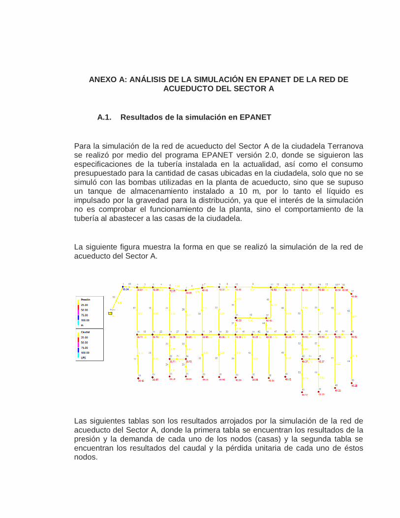
ANEXO A: ANÁLISIS DE LA SIMULACIÓN EN EPANET DE LA RED DE ACUEDUCTO DEL SECTOR A
A.1. Resultados de la simulación en EPANET
Para la simulación de la red de acueducto del Sector A de la ciudadela Terranova se realizó por medio del programa EPANET versión 2.0, donde se siguieron las especificaciones de la tubería instalada en la actualidad, así como el consumo presupuestado para la cantidad de casas ubicadas en la ciudadela, solo que no se simuló con las bombas utilizadas en la planta de acueducto, sino que se supuso un tanque de almacenamiento instalado a 10 m, por lo tanto el líquido es impulsado por la gravedad para la distribución, ya que el interés de la simulación no es comprobar el funcionamiento de la planta, sino el comportamiento de la tubería al abastecer a las casas de la ciudadela.
La siguiente figura muestra la forma en que se realizó la simulación de la red de acueducto del Sector A.
Las siguientes tablas son los resultados arrojados por la simulación de la red de acueducto del Sector A, donde la primera tabla se encuentran los resultados de la presión y la demanda de cada uno de los nodos (casas) y la segunda tabla se encuentran los resultados del caudal y la pérdida unitaria de cada uno de éstos nodos.


A.2. Puntos de sensado propuestos en el Sector A
A.3. Puntos de sensado propuestos en la planta
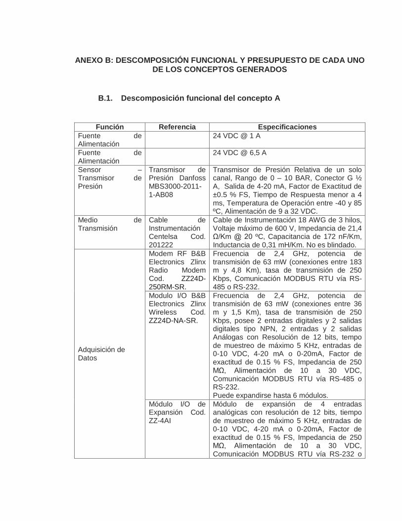
ANEXO B: DESCOMPOSICIÓN FUNCIONAL Y PRESUPUESTO DE CADA UNO DE LOS CONCEPTOS GENERADOS
B.1. Descomposición funcional del concepto A
Función Referencia Especificaciones Fuente de Alimentación
24 VDC @ 1 A
Fuente de Alimentación
24 VDC @ 6,5 A
Sensor – Transmisor de Presión
Transmisor de Presión Danfoss MBS3000-2011-1-AB08
Transmisor de Presión Relativa de un solo canal, Rango de 0 – 10 BAR, Conector G ½ A, Salida de 4-20 mA, Factor de Exactitud de ±0.5 % FS, Tiempo de Respuesta menor a 4 ms, Temperatura de Operación entre -40 y 85 ºC, Alimentación de 9 a 32 VDC.
Medio de Transmisión
Cable de Instrumentación Centelsa Cod. 201222
Cable de Instrumentación 18 AWG de 3 hilos, Voltaje máximo de 600 V, Impedancia de 21,4 Ω/Km @ 20 ºC, Capacitancia de 172 nF/Km, Inductancia de 0,31 mH/Km. No es blindado.
Adquisición de Datos
Modem RF B&B Electronics Zlinx Radio Modem Cod. ZZ24D-250RM-SR.
Frecuencia de 2,4 GHz, potencia de transmisión de 63 mW (conexiones entre 183 m y 4,8 Km), tasa de transmisión de 250 Kbps, Comunicación MODBUS RTU vía RS-485 o RS-232.
Modulo I/O B&B Electronics Zlinx Wireless Cod. ZZ24D-NA-SR.
Frecuencia de 2,4 GHz, potencia de transmisión de 63 mW (conexiones entre 36 m y 1,5 Km), tasa de transmisión de 250 Kbps, posee 2 entradas digitales y 2 salidas digitales tipo NPN, 2 entradas y 2 salidas Análogas con Resolución de 12 bits, tempo de muestreo de máximo 5 KHz, entradas de 0-10 VDC, 4-20 mA o 0-20mA, Factor de exactitud de 0.15 % FS, Impedancia de 250 MΩ, Alimentación de 10 a 30 VDC, Comunicación MODBUS RTU vía RS-485 o RS-232. Puede expandirse hasta 6 módulos.
Módulo I/O de Expansión Cod. ZZ-4AI
Módulo de expansión de 4 entradas analógicas con resolución de 12 bits, tiempo de muestreo de máximo 5 KHz, entradas de 0-10 VDC, 4-20 mA o 0-20mA, Factor de exactitud de 0.15 % FS, Impedancia de 250 MΩ, Alimentación de 10 a 30 VDC, Comunicación MODBUS RTU vía RS-232 o

RS-485. Sistema de Procesamiento Digital
Computadora Lenovo M57e (9482-F4S)
Procesador Intel Core 2 Duo, Tarjeta RAM de 1 GB, Disco Duro de 160 GB, Tarjeta de Video Intel Graphics Media Acelerator 3100, Monitor de 17’’.
Software de Gestión y Monitoreo
Desarrollado por el equipo diseñador.
Generar un diagrama esquemático de la red de acueducto, Visualizar datos de la presión en los puntos sensados, Generar alarmas, Permitir tanto muestreo automático (cada hora) como manual, Establecer y gestionar comunicaciones con dispositivos de adquisición de datos, Tomar y almacenar datos muestreados.
Base de Datos MySQL Diversos tipos de datos, conexiones hasta 1000 simultáneamente.
Servidor WEB Apache HTTP Server
Multiprotocolo, multiplataforma, multilenguaje, Soporta PHP, permite hasta 500 conexiones simultáneas.
B.2. Presupuesto del concepto A
Referencia Unidad Costo Unitario Cantidad Costo Total MySQL unitario $ - 1 $ - Apache HTTP Server unitario $ - 1 $ - Linksys Wireless-g Access Point Wap54g unitario $ 180.000,00 1 $ 180.000,00
Computadora Lenovo M57e unitario $ 1.500.000,00 1 $ 1.500.000,00 Tarjeta PCI Encore Wireless unitario $ 50.000,00 1 $ 50.000,00 Conversor RS-232 a RS-485 unitario $ 200.000,00 1 $ 200.000,00 Fuente de Alimentación Swicheada de 24 VDC @ 6,5 A unitario $ 160.000,00 2 $ 320.000,00
Modulo B&B Electronics Zlinx Wireless Cod. ZZ24D-NC-SR unitario $ 809.600,00 2 $ 1.619.200,00
Módulo I/O de Expansión B&B Electronics Cod. ZZ-4AI unitario $ 569.800,00 2
$ 1.139.600,00
Transmisor de Presión Danfoss MBS3000-2011-1-AB08 unitario $ 542.300,00 5 $ 2.711.500,00
Manómetro unitario $ 40.000,00 1 $ 40.000,00 Accesorios Eléctricos unitario $ 50.000,00 1 $ 50.000,00 Caja en Acrílico (20x20x20) unitario $ 30.000,00 5 $ 150.000,00 Caja en Acrílico (40x40x20) unitario $ 60.000,00 5 $ 300.000,00

Caja de Lamina Galvanizada (50x40x20) unitario $ 40.000,00 1 $ 40.000,00
Cable de Instrumentación Centelsa Cod. 201224 metro $ 4.059,00 500 $ 2.029.500,00
Tubo PAVCO Conduit 3/4 Cod. 12478 3 metros $ 3.200,00 20 $ 64.000,00
Caja Octagonal PAVCO Cod. 10590 unitario $ 1.238,00 0 $ -
Curvas 90º Conduit 3/4 PAVCO Cod. 11078 unitario $ 663,00 0 $ -
Uniones PAVCO Cod. 12856 unitario $ 302,00 20 $ 6.040,00 Tubo PAVCO Presión 1/2 Cod. 12633 6
metros $ 1.654,00 1 $ 1.654,00
Codo 90º PAVCO 1/2 Cod. 10855 unitario $ 282,00 10 $ 2.820,00
Tee PAVCO 1/2 Cod. 12060 unitario $ 373,00 5 $ 1.865,00 Tapón Roscado PAVCO 1/2 Cod. 11888 unitario $ 220,00 5 $ 1.100,00
Llave de Paso Mariposa 1/2 unitario $ 1.000,00 5 $ 5.000,00 SUBTOTAL $ 10.412.279,00 IVA 16% $ 1.665.964,64 TOTAL $ 12.078.243,64
B.3. Descomposición funcional del concepto B
Función Referencia Especificaciones Fuente de Alimentación
24 VDC @ 5 A
Sensor – Transmisor
Transmisor de Presión Danfoss MBS3000-2011-1-AB08
Transmisor de Presión Relativa de un solo canal, Rango de 0 – 10 BAR, Conector G ½ A, Salida de 4-20 mA, Factor de Exactitud de ±0.5 % FS, Tiempo de Respuesta menor a 4 ms, Temperatura de Operación entre -40 y 85 ºC, Alimentación de 9 a 32 VDC.
Medio de Transmisión
Cable de Instrumentación Centelsa Cod. 201222, 201224 y 201225
Cable de Instrumentación 18 AWG de 3, 4 y 6 hilos, Voltaje máximo de 600 V, Impedancia de 21,4 Ω/Km @ 20 ºC, Capacitancia de 172 nF/Km, Inductancia de 0,31 mH/Km. No es blindado.
Adquisición de Datos
Modulo B&B Electronics Zlinx Wired 485 Cod. ZZ-NA-485 y Módulo de
2 entradas digitales y 2 salidas digitales tipo NPN, 2 entradas y 2 salidas Análogas con Resolución de 12 bits, tempo de muestreo de máximo 5 KHz, entradas de 0-10 VDC, 4-20 mA o 0-20mA, Factor de exactitud de 0.15 %

Expansión Cod. ZZ-4AI
FS, Impedancia de 250 MΩ, Alimentación de 10 a 30 VDC, Comunicación MODBUS RTU vía RS-232 o RS-485. El Módulo de Expansión posee 4 entradas análogas con las mismas especificaciones anteriores. Puede expandirse hasta 6 módulos.
Computadora Computadora Lenovo M57e (9482-F4S)
Procesador Intel Core 2 Duo, Tarjeta RAM de 1 GB, Disco Duro de 160 GB, Tarjeta de Video Intel Graphics Media Acelerator 3100, Monitor de 17’’.
Software de Control y Monitoreo
Desarrollado por el equipo diseñador.
Generar un diagrama esquemático de la red de acueducto, Visualizar datos de la presión en los puntos sensados, Generar alarmas, Permitir tanto muestreo automático (cada hora) como manual, Establecer y gestionar comunicaciones con dispositivos de adquisición de datos, Tomar y almacenar datos muestreados.
Base de Datos MySQL Diversos tipos de datos, conexiones hasta 1000 simultáneamente.
Servidor WEB Apache HTTP Server
Multiprotocolo, multiplataforma, multilenguaje, Soporta PHP, permite hasta 500 conexiones simultáneas.
B.4. Presupuesto del concepto B
Referencia Unidad Costo Unitario Cantidad Costo Total MySQL unitario $ - 1 $ - Apache HTTP Server unitario $ - 1 $ - Linksys Wireless-g Access Point Wap54g unitario $ 180.000,00 1 $ 180.000,00
Computadora Lenovo M57e unitario $ 1.500.000,00 1 $ 1.500.000,00 Tarjeta PCI Encore Wireless unitario $ 50.000,00 1 $ 50.000,00 Conversor RS-232 a RS-485 unitario $ 200.000,00 1 $ 200.000,00 Fuente de Alimentación Swicheada de 24 VDC @ 5 A unitario $ 160.000,00 1 $ 160.000,00
Modulo I/O B&B Electronics Zlinx Wired 485 Cod. ZZ-NC-485
unitario $ 547.800,00 1 $ 547.800,00
Módulo I/O de Expansión B&B Electronics Cod. ZZ-4AI unitario $ 569.800,00 1 $ 569.800,00

Transmisor de Presión Danfoss MBS3000-2011-1-AB08 unitario $ 542.300,00 5 $ 2.711.500,00
Manómetro unitario $ 40.000,00 1 $ 40.000,00 Accesorios Eléctricos unitario $ 50.000,00 1 $ 50.000,00 Caja en Acrílico (20x20x20) unitario $ 30.000,00 5 $ 150.000,00 Caja de Lamina Galvanizada (50x40x20) unitario $ 40.000,00 1 $ 40.000,00
Cable de Instrumentación x3 hilos Centelsa Cod. 201222 metro $ 3.329,00 135 $ 449.415,00
Cable de Instrumentación x4 hilos Centelsa Cod. 201224 metro $ 4.059,00 60 $ 243.540,00
Cable de Instrumentación x6 hilos Centelsa Cod. 201225 metro $ 6.086,00 165 $ 1.004.190,00
Tubo PAVCO Conduit 3/4 Cod. 12478 3 metros $ 3.200,00 154 $ 492.800,00
Caja Octagonal PAVCO Cod. 10590 unitario $ 1.238,00 6 $ 7.428,00
Curvas 90º Conduit 3/4 PAVCO Cod. 11078 unitario $ 663,00 12 $ 7.956,00
Uniones PAVCO Cod. 12856 unitario $ 302,00 200 $ 60.400,00 Tubo PAVCO Presión 1/2 Cod. 12633 6 metros $ 1.654,00 1 $ 1.654,00
Codo 90º PAVCO 1/2 Cod. 10855 unitario $ 282,00 10 $ 2.820,00
Tee PAVCO 1/2 Cod. 12060 unitario $ 373,00 5 $ 1.865,00 Tapón Roscado PAVCO 1/2 Cod. 11888 unitario $ 220,00 5 $ 1.100,00
Llave de Paso Mariposa 1/2 unitario $ 1.000,00 5 $ 5.000,00
SUBTOTAL $ 8.477.268,00 IVA 16% $ 1.356.362,88 TOTAL $ 9.833.630,88
B.5. Descomposición funcional del concepto C
Función Referencia Especificaciones Fuente de Alimentación
24 VDC @ 5 A
Sensor – Transmisor
Transmisor de Presión Danfoss MBS3000-2011-1-AB08
Transmisor de Presión Relativa de un solo canal, Rango de 0 – 10 BAR, Conector G ½ A, Salida de 4-20 mA, Factor de Exactitud de ±0.5 % FS, Tiempo de Respuesta menor a 4

ms, Temperatura de Operación entre -40 y 85 ºC, Alimentación de 9 a 32 VDC.
Medio de Transmisión
Cable de Instrumentación Centelsa Cod. 201222, 201224 y 201225
Cable de Instrumentación 18 AWG de 3, 4 y 6 hilos, Voltaje máximo de 600 V, Impedancia de 21,4 Ω/Km @ 20 ºC, Capacitancia de 172 nF/Km, Inductancia de 0,31 mH/Km. No es blindado.
Adquisición de Datos
Modulo Desin DAS 8000
8 entradas y 8 salidas digitales, 8 entradas analógicas, resolución de 40.000 puntos, rango pt 100, 0-50 mV, 4-20 mA o 0-20 mA, tiempo de muestre de 125 ms, factor de exactitud de 0,1 % FS, Alimentación de 110/220 VAC, Alarmas, Conexión a impresora, Comunicación MODBUS RTU vía RS-232 o RS-485
Computadora Computadora Lenovo M57e (9482-F4S)
Procesador Intel Core 2 Duo, Tarjeta RAM de 1 GB, Disco Duro de 160 GB, Tarjeta de Video Intel Graphics Media Acelerator 3100, Monitor de 17’’.
Software de Control y Monitoreo
Desarrollado por el equipo diseñador.
Generar un diagrama esquemático de la red de acueducto, Visualizar datos de la presión en los puntos sensados, Generar alarmas, Permitir tanto muestreo automático (cada hora) como manual, Establecer y gestionar comunicaciones con dispositivos de adquisición de datos, Tomar y almacenar datos muestreados.
Base de Datos MySQL Diversos tipos de datos, conexiones hasta 1000 simultáneamente.
Servidor WEB Apache HTTP Server
Multiprotocolo, multiplataforma, multilenguaje, Soporta PHP, permite hasta 500 conexiones simultáneas.
B.6. Presupuesto del concepto C
Referencia Unidad Costo Unitario Cantidad Costo Total MySQL unitario $ - 1 $ - Apache HTTP Server unitario $ - 1 $ - Linksys Wireless-g Access Point Wap54g unitario $ 180.000,00 1 $ 180.000,00
Computadora Lenovo M57e unitario $ 1.500.000,00 1 $ 1.500.000,00 Tarjeta PCI Encore Wireless unitario $ 50.000,00 1 $ 50.000,00 Conversor RS-232 a RS-485 unitario $ 200.000,00 1 $ 200.000,00

Fuente de Alimentación Swicheada de 24 VDC @ 5 A unitario $ 160.000,00 1 $ 160.000,00
Módulo Desin DAS 8000 unitario $ 2.340.000,00 1 $ 2.340.000,00 Transmisor de Presión Danfoss MBS3000-2011-1-AB08 unitario $ 542.300,00 5 $ 2.711.500,00
Manómetro unitario $ 40.000,00 1 $ 40.000,00 Accesorios Eléctricos unitario $ 50.000,00 1 $ 50.000,00 Caja en Acrílico (20x20x20) unitario $ 30.000,00 5 $ 150.000,00 Caja de Lamina Galvanizada (50x40x20) unitario $ 40.000,00 1 $ 40.000,00
Cable de Instrumentación x3 hilos Centelsa Cod. 201222 metro $ 3.329,00 135 $ 449.415,00
Cable de Instrumentación x4 hilos Centelsa Cod. 201224 metro $ 4.059,00 60 $ 243.540,00
Cable de Instrumentación x6 hilos Centelsa Cod. 201225 metro $ 6.086,00 165 $ 1.004.190,00
Tubo PAVCO Conduit 3/4 Cod. 12478 3 metros $ 3.200,00 154 $ 492.800,00
Caja Octagonal PAVCO Cod. 10590 unitario $ 1.238,00 6 $ 7.428,00
Curvas 90º Conduit 3/4 PAVCO Cod. 11078 unitario $ 663,00 12 $ 7.956,00
Uniones PAVCO Cod. 12856 unitario $ 302,00 200 $ 60.400,00 Tubo PAVCO Presión 1/2 Cod. 12633 6 metros $ 1.654,00 1 $ 1.654,00
Codo 90º PAVCO 1/2 Cod. 10855 unitario $ 282,00 10 $ 2.820,00
Tee PAVCO 1/2 Cod. 12060 unitario $ 373,00 5 $ 1.865,00 Tapón Roscado PAVCO 1/2 Cod. 11888 unitario $ 220,00 5 $ 1.100,00
Llave de Paso Mariposa 1/2 unitario $ 1.000,00 5 $ 5.000,00
SUBTOTAL $ 9.699.668,00 IVA 16% $ 1.551.946,88 TOTAL $ 11.251.614,88
B.7. Descomposición funcional del concepto D
Función Referencia Especificaciones Fuente de Alimentación
24 VDC @ 5 A
Sensor – Transmisor de Transmisor de Presión Relativa de un solo

Transmisor Presión Danfoss MBS3000-2011-1-AB08
canal, Rango de 0 – 10 BAR, Conector G ½ A, Salida de 4-20 mA, Factor de Exactitud de ±0.5 % FS, Tiempo de Respuesta menor a 4 ms, Temperatura de Operación entre -40 y 85 ºC, Alimentación de 9 a 32 VDC.
Medio de Transmisión
Cable de Instrumentación Centelsa Cod. 201222, 201224 y 201225
Cable de Instrumentación 18 AWG de 3, 4 y 6 hilos, Voltaje máximo de 600 V, Impedancia de 21,4 Ω/Km @ 20 ºC, Capacitancia de 172 nF/Km, Inductancia de 0,31 mH/Km. No es blindado.
Adquisición de Datos
Desarrollado por el equipo diseñador
Resolución: 12 bits, Tiempo de Conversión de 1 ms, Entrada de 4-20 mA @ 24 VDC, 16 entradas análogas, 8 entradas y salidas digitales (relé), Comunicación MODBUS RTU vía RS-485. Alimentación de 24 VDC.
Computadora Computadora Lenovo M57e (9482-F4S)
Procesador Intel Core 2 Duo, Tarjeta RAM de 1 GB, Disco Duro de 160 GB, Tarjeta de Video Intel Graphics Media Acelerator 3100, Monitor de 17’’.
Software de Control y Monitoreo
Desarrollado por el equipo diseñador.
Generar un diagrama esquemático de la red de acueducto, Visualizar datos de la presión en los puntos sensados, Generar alarmas, Permitir tanto muestreo automático (cada hora) como manual, Establecer y gestionar comunicaciones con dispositivos de adquisición de datos, Tomar y almacenar datos muestreados.
Base de Datos MySQL Diversos tipos de datos, conexiones hasta 1000 simultáneamente.
Servidor WEB Apache HTTP Server
Multiprotocolo, multiplataforma, multilenguaje, Soporta PHP, permite hasta 500 conexiones simultáneas.
B.8. Presupuesto del concepto D
Referencia Unidad Costo Unitario Cantidad Costo Total MySQL unitario $ - 1 $ - Apache HTTP Server unitario $ - 1 $ - Linksys Wireless-g Access Point Wap54g unitario $ 180.000,00 1 $ 180.000,00
Computadora Lenovo M57e unitario $ 1.500.000,00 1 $ 1.500.000,00 Tarjeta PCI Encore Wireless unitario $ 50.000,00 1 $ 50.000,00 Conversor RS-232 a RS-485 unitario $ 200.000,00 1 $ 200.000,00

Fuente de Alimentación Swicheada de 24 VDC @ 5 A unitario $ 160.000,00 1 $ 160.000,00
Módulo Desarrollado por el Equipo Diseñador unitario $ 400.000,00 1 $ 400.000,00
Transmisor de Presión Danfoss MBS3000-2011-1-AB08 unitario $ 542.300,00 5 $ 2.711.500,00
Manómetro unitario $ 40.000,00 1 $ 40.000,00 Accesorios Eléctricos unitario $ 50.000,00 1 $ 50.000,00 Caja en Acrílico (20x20x20) unitario $ 30.000,00 5 $ 150.000,00 Caja de Lamina Galvanizada (50x40x20) unitario $ 40.000,00 1 $ 40.000,00
Cable de Instrumentación x3 hilos Centelsa Cod. 201222 metro $ 3.329,00 135 $ 449.415,00
Cable de Instrumentación x4 hilos Centelsa Cod. 201224 metro $ 4.059,00 60 $ 243.540,00
Cable de Instrumentación x6 hilos Centelsa Cod. 201225 metro $ 6.086,00 165 $ 1.004.190,00
Tubo PAVCO Conduit 3/4 Cod. 12478 3 metros $ 3.200,00 154 $ 492.800,00
Caja Octagonal PAVCO Cod. 10590 unitario $ 1.238,00 6 $ 7.428,00
Curvas 90º Conduit 3/4 PAVCO Cod. 11078 unitario $ 663,00 12 $ 7.956,00
Uniones PAVCO Cod. 12856 unitario $ 302,00 200 $ 60.400,00 Tubo PAVCO Presión 1/2 Cod. 12633 6 metros $ 1.654,00 1 $ 1.654,00
Codo 90º PAVCO 1/2 Cod. 10855 unitario $ 282,00 10 $ 2.820,00
Tee PAVCO 1/2 Cod. 12060 unitario $ 373,00 5 $ 1.865,00 Tapón Roscado PAVCO 1/2 Cod. 11888 unitario $ 220,00 5 $ 1.100,00
Llave de Paso Mariposa 1/2 unitario $ 1.000,00 5 $ 5.000,00
SUBTOTAL $ 7.759.668,00 IVA 16% $ 1.241.546,88 TOTAL $ 9.001.214,88
B.9. Descomposición funcional del concepto E
Función Referencia Especificaciones Fuente de Alimentación
24 VDC @ 5 A
Sensor – Transmisor de Transmisor de Presión Relativa de un solo

Transmisor Presión Danfoss MBS3000-2011-1-AB08
canal, Rango de 0 – 10 BAR, Conector G ½ A, Salida de 4-20 mA, Factor de Exactitud de ±0.5 % FS, Tiempo de Respuesta menor a 4 ms, Temperatura de Operación entre -40 y 85 ºC, Alimentación de 9 a 32 VDC.
Medio de Transmisión
Cable de Instrumentación Centelsa Cod. 201222, 201224 y 201225
Cable de Instrumentación 18 AWG de 3, 4 y 6 hilos, Voltaje máximo de 600 V, Impedancia de 21,4 Ω/Km @ 20 ºC, Capacitancia de 172 nF/Km, Inductancia de 0,31 mH/Km. No es blindado.
Adquisición de Datos
Beijer Electronics, PLC Koyo Series 5, Dos Expansiones F0-4AD-1
8 entradas y 8 salidas digitales, Dos puertos de comunicación, Contador de 5 KHz o interrupción, 2K de memoria de programa, 4K de memoria de usuario, 4 bucles PID, Alimentación de 24 VDC, Comunicación MODBUS RTU/Directnet. El módulo de expansión posee 4 entradas análogas de 12 bits de resolución, entradas de 0-20 mA y 4-20 mA.
Computadora Computadora Lenovo M57e (9482-F4S)
Procesador Intel Core 2 Duo, Tarjeta RAM de 1 GB, Disco Duro de 160 GB, Tarjeta de Video Intel Graphics Media Acelerator 3100, Monitor de 17’’.
Software de Control y Monitoreo
Desarrollado por el equipo diseñador.
Generar un diagrama esquemático de la red de acueducto, Visualizar datos de la presión en los puntos sensados, Generar alarmas, Permitir tanto muestreo automático (cada hora) como manual, Establecer y gestionar comunicaciones con dispositivos de adquisición de datos, Tomar y almacenar datos muestreados.
Base de Datos MySQL Diversos tipos de datos, conexiones hasta 1000 simultáneamente.
Servidor WEB Apache HTTP Server
Multiprotocolo, multiplataforma, multilenguaje, Soporta PHP, permite hasta 500 conexiones simultáneas.
B.10. Presupuesto del concepto E
Referencia Unidad Costo Unitario Cantidad Costo Total MySQL unitario $ - 1 $ - Apache HTTP Server unitario $ - 1 $ - Linksys Wireless-g Access Point Wap54g unitario $ 180.000,00 1 $ 180.000,00
Computadora Lenovo M57e unitario $ 1.500.000,00 1 $ 1.500.000,00
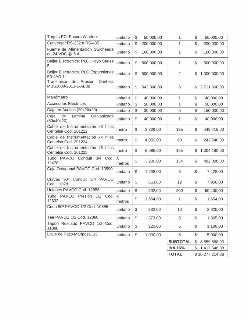
Tarjeta PCI Encore Wireless unitario $ 50.000,00 1 $ 50.000,00 Conversor RS-232 a RS-485 unitario $ 200.000,00 1 $ 200.000,00 Fuente de Alimentación Swicheada de 24 VDC @ 5 A unitario $ 160.000,00 1 $ 160.000,00
Beijer Electronics, PLC Koyo Series 5
unitario $ 500.000,00 1 $ 500.000,00
Beijer Electronics, PLC Expansiones F0-4AD-1
unitario $ 500.000,00 2 $ 1.000.000,00
Transmisor de Presión Danfoss MBS3000-2011-1-AB08 unitario $ 542.300,00 5 $ 2.711.500,00
Manómetro unitario $ 40.000,00 1 $ 40.000,00 Accesorios Eléctricos unitario $ 50.000,00 1 $ 50.000,00 Caja en Acrílico (20x20x20) unitario $ 30.000,00 5 $ 150.000,00 Caja de Lamina Galvanizada (50x40x20) unitario $ 40.000,00 1 $ 40.000,00
Cable de Instrumentación x3 hilos Centelsa Cod. 201222 metro $ 3.329,00 135 $ 449.415,00
Cable de Instrumentación x4 hilos Centelsa Cod. 201224 metro $ 4.059,00 60 $ 243.540,00
Cable de Instrumentación x6 hilos Centelsa Cod. 201225 metro $ 6.086,00 165 $ 1.004.190,00
Tubo PAVCO Conduit 3/4 Cod. 12478
3 metros $ 3.200,00 154 $ 492.800,00
Caja Octagonal PAVCO Cod. 10590 unitario $ 1.238,00 6 $ 7.428,00
Curvas 90º Conduit 3/4 PAVCO Cod. 11078 unitario $ 663,00 12 $ 7.956,00
Uniones PAVCO Cod. 12856 unitario $ 302,00 200 $ 60.400,00 Tubo PAVCO Presión 1/2 Cod. 12633
6 metros $ 1.654,00 1 $ 1.654,00
Codo 90º PAVCO 1/2 Cod. 10855 unitario $ 282,00 10 $ 2.820,00
Tee PAVCO 1/2 Cod. 12060 unitario $ 373,00 5 $ 1.865,00 Tapón Roscado PAVCO 1/2 Cod. 11888 unitario $ 220,00 5 $ 1.100,00
Llave de Paso Mariposa 1/2 unitario $ 1.000,00 5 $ 5.000,00
SUBTOTAL $ 8.859.668,00 IVA 16% $ 1.417.546,88 TOTAL $ 10.277.214,88
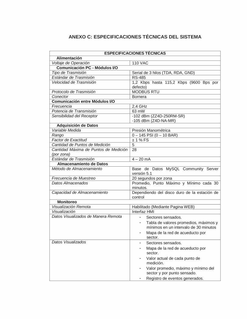
ANEXO C: ESPECIFICACIONES TÉCNICAS DEL SISTEMA
ESPECIFICACIONES TÉCNICAS Alimentación
Voltaje de Operación 110 VAC Comunicación PC - Módulos I/O
Tipo de Trasmisión Serial de 3 hilos (TDA, RDA, GND) Estándar de Trasmisión RS-485 Velocidad de Trasmisión 1,2 Kbps hasta 115,2 Kbps (9600 Bps por
defecto) Protocolo de Trasmisión MODBUS RTU Conector Bornera Comunicación entre Módulos I/O Frecuencia 2,4 GHz Potencia de Transmisión 63 mW Sensibilidad del Receptor -102 dBm (ZZ4D-250RM-SR)
-105 dBm (Z4D-NA-MR) Adquisición de Datos
Variable Medida Presión Manométrica Rango 0 – 145 PSI (0 – 10 BAR) Factor de Exactitud ± 1 % FS Cantidad de Puntos de Medición 5 Cantidad Máxima de Puntos de Medición (por zona)
28
Estándar de Trasmisión 4 – 20 mA Almacenamiento de Datos
Método de Almacenamiento Base de Datos MySQL Community Server versión 5.1
Frecuencia de Muestreo 20 segundos por zona Datos Almacenados Promedio, Punto Máximo y Mínimo cada 30
minutos. Capacidad de Almacenamiento Dependiendo del disco duro de la estación de
control Monitoreo
Visualización Remota Habilitado (Mediante Pagina WEB) Visualización Interfaz HMI Datos Visualizados de Manera Remota - Sectores sensados.
- Tabla de valores promedios, máximos y mínimos en un intervalo de 30 minutos
- Mapa de la red de acueducto por sector.
Datos Visualizados - Sectores sensados. - Mapa de la red de acueducto por
sector. - Valor actual de cada punto de
medición. - Valor promedio, máximo y mínimo del
sector y por punto sensado. - Registro de eventos generados.

ANEXO D: PLANOS DE LAS CARCASAS PROPUESTAS
Si se encuentra leyendo el documento electrónico, presione los links siguientes para abrir el respectivo plano. En caso de estar leyendo el documento escrito, las siguientes páginas corresponden a las carcasas, siguiendo el orden de la siguiente lista.
- Carcasa de lamina galvanizada tipo 1
- Carcasa de lamina galvanizada tipo 2
- Carcasa de lamina galvanizada tipo 3
- Carcasa en acrílico tipo 1
- Carcasa en acrílico tipo 2
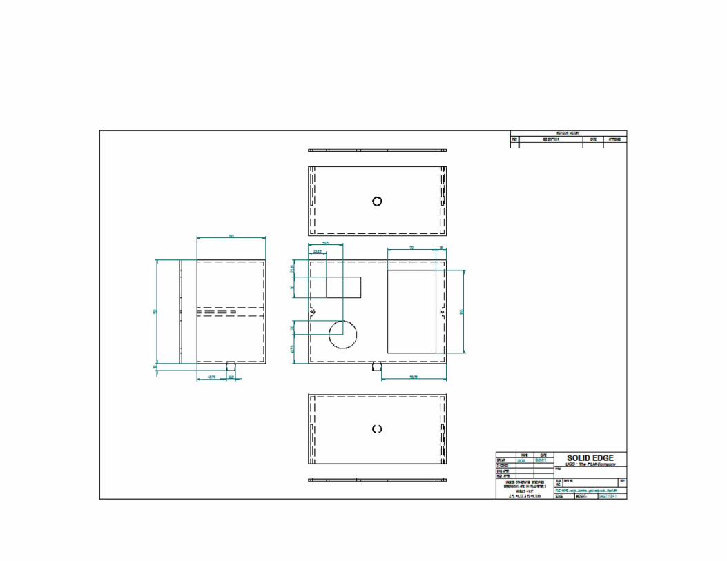

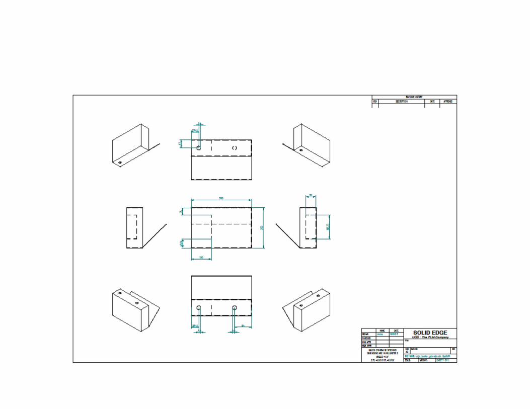


ANEXO E: ESPECIFICACIONES DE LA BASE DE DATOS
E.1. Organización de la base de datos
Nombre de la Base de Datos Tablas Implementadas
servicios_terranova planta sector_b
E.2. Valores almacenados en la base de datos en la tabla del Sector A
Índice Dato Nombre del dato
Tipo de dato
Valor Inicial
1 Fecha y Hora de almacenamiento fecha_hora DateTime 2009-01-01 00:00:00
2 Set-Point set_point Double 0 3 Promedio global _abs Double 0 4 Máximo global _max Double 0 5 Mínimo global _min Double 0 6 Promedio sensor 1 _abs1 Double 0 7 Máximo sensor 1 _max1 Double 0 8 Mínimo sensor 1 _min1 Double 0 9 Promedio sensor 2 _abs2 Double 0 10 Máximo sensor 2 _max2 Double 0 11 Mínimo sensor 2 _min2 Double 0 12 Promedio sensor 3 _abs3 Double 0 13 Máximo sensor 3 _max3 Double 0 14 Mínimo sensor 3 _min3 Double 0

E.3. Valores almacenados en la base de datos en la tabla de la planta
Índice Dato Nombre del dato
Tipo de dato
Valor Inicial
1 Fecha y Hora de almacenamiento fecha_hora DateTime 2009-01-01 00:00:00
2 Set-Point set_point Double 0 3 Promedio global _abs Double 0 4 Máximo global _max Double 0 5 Mínimo global _min Double 0 6 Promedio sensor 1 _abs1 Double 0 7 Máximo sensor 1 _max1 Double 0 8 Mínimo sensor 1 _min1 Double 0 9 Promedio sensor 2 _abs2 Double 0 10 Máximo sensor 2 _max2 Double 0 11 Mínimo sensor 2 _min2 Double 0

ANEXO F: MANUAL DE USO
Las siguientes páginas forman el manual tanto de instalación como de uso, compuesto de los siguientes temas:
- Requisitos
- Instalación
- Configuración
- Uso
- Solución de problemas.
(Si se encuentra leyendo el documento electrónico, haga click aquí para abrir el manual)

DRAWNCHECKEDENG APPRMGR APPR
UNLE SS OTHERWI SE SPECIFIEDDIME NSIONS ARE IN MILLIMETER S
ANGLE S ±X.X°2 PL ±X.XX 3 PL ±X. XXX
NAMEcarlos
DATE10/01/0 9 SOLID EDGE
UGS - The PLM CompanyTITLE
SIZEA2
DWG NO REV
FILE NAME : caja_acriclico_tipo1.dft
SCALE: WEIGHT : SHEET 1 OF 1
REVI SION HISTORY
REV DES CRIPTIO N DATE APPROVED
227
2020
10
10
150 53147
160
97
130
7510
23,8
132
,3135
,3728
,23
31,9730,2731,6331,63
59,8
11,5
100

DRAWNCHECKEDENG APPRMGR APPR
UNLE SS OTHERWI SE SPECIFIEDDIME NSIONS ARE IN MILLIMETER S
ANGLE S ±X.X°2 PL ±X.XX 3 PL ±X. XXX
NAMEcarlos
DATE10/01/0 9 SOLID EDGE
UGS - The PLM CompanyTITLE
SIZEA2
DWG NO REV
FILE NAME : caja_acriclico_tipo2.dft
SCALE: WEIGHT : SHEET 1 OF 1
REVI SION HISTORY
REV DES CRIPTIO N DATE APPROVED
11020
10
100
30
20
2
7,5
32
20 7,5
32
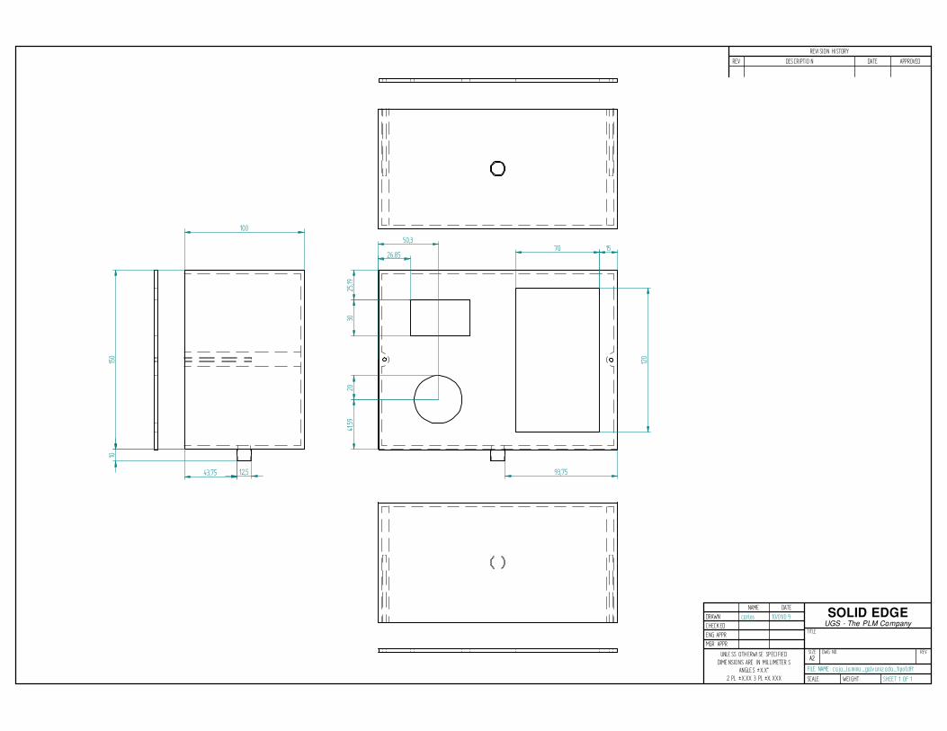
DRAWNCHECKEDENG APPRMGR APPR
UNLE SS OTHERWI SE SPECIFIEDDIME NSIONS ARE IN MILLIMETER S
ANGLE S ±X.X°2 PL ±X.XX 3 PL ±X. XXX
NAMEcarlos
DATE10/01/0 9 SOLID EDGE
UGS - The PLM CompanyTITLE
SIZEA2
DWG NO REV
FILE NAME : caja_lamina _galv aniz ada_tipo1.dft
SCALE: WEIGHT : SHEET 1 OF 1
REVI SION HISTORY
REV DES CRIPTIO N DATE APPROVED
150
100
10
3025
,1941
,5920
120
70 1526,85
50,3
93,7512,543,75
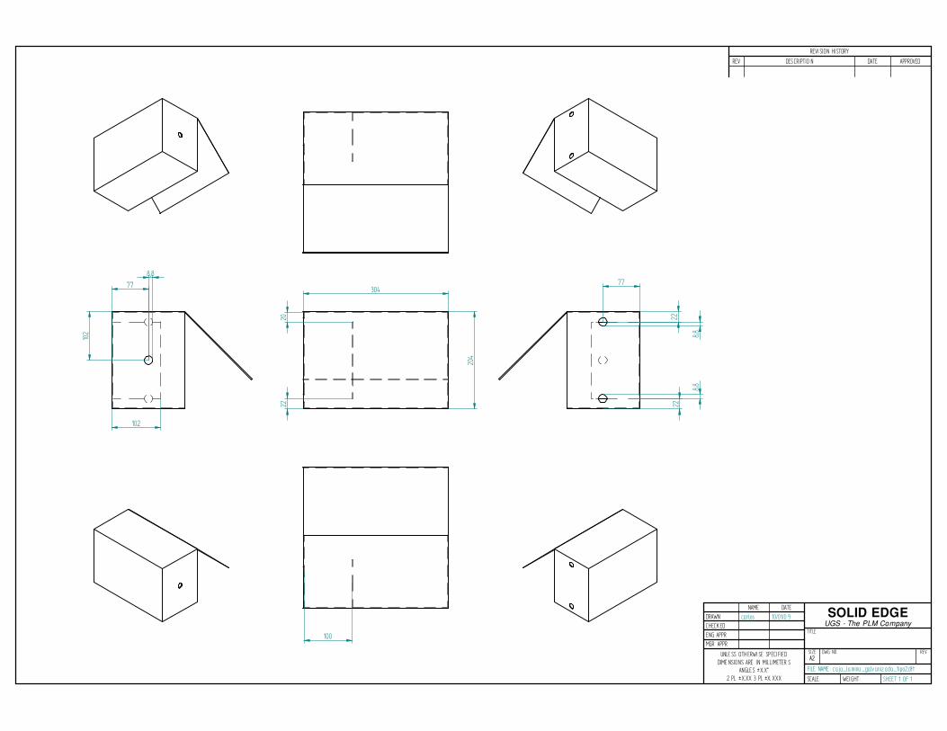
DRAWNCHECKEDENG APPRMGR APPR
UNLE SS OTHERWI SE SPECIFIEDDIME NSIONS ARE IN MILLIMETER S
ANGLE S ±X.X°2 PL ±X.XX 3 PL ±X. XXX
NAMEcarlos
DATE10/01/0 9 SOLID EDGE
UGS - The PLM CompanyTITLE
SIZEA2
DWG NO REV
FILE NAME : caja_lamina _galv aniz ada_tipo2.dft
SCALE: WEIGHT : SHEET 1 OF 1
REVI SION HISTORY
REV DES CRIPTIO N DATE APPROVED
204
2022
30477
8,8
102
102
22
8,8
22
8,8
77
100
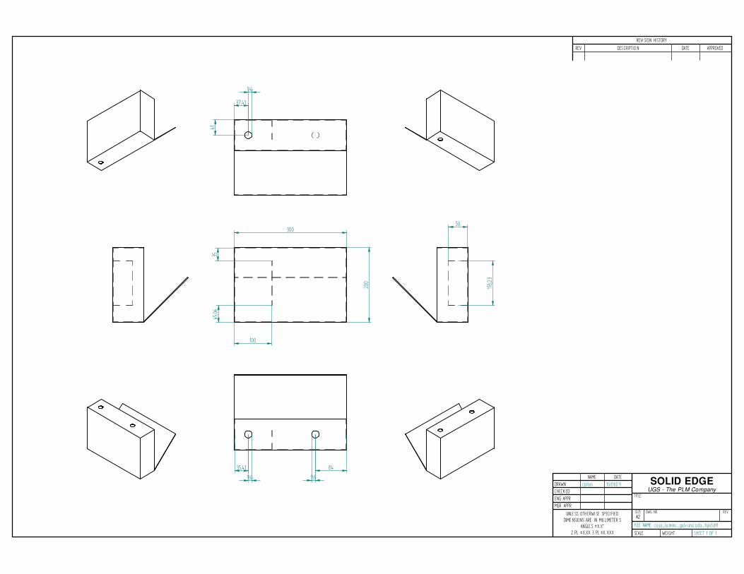
DRAWNCHECKEDENG APPRMGR APPR
UNLE SS OTHERWI SE SPECIFIEDDIME NSIONS ARE IN MILLIMETER S
ANGLE S ±X.X°2 PL ±X.XX 3 PL ±X. XXX
NAMEcarlos
DATE10/01/0 9 SOLID EDGE
UGS - The PLM CompanyTITLE
SIZEA2
DWG NO REV
FILE NAME : caja_lamina _galv aniz ada_tipo3.dft
SCALE: WEIGHT : SHEET 1 OF 1
REVI SION HISTORY
REV DES CRIPTIO N DATE APPROVED
300
200
45,06
35
100
37,41
9,6
41
118,2
3
50
35,41
9,6
84
9,6